laser-cut enclosure design - ideate courses · overview this tutorial focuses on case design. if...
TRANSCRIPT
Laser-Cut Enclosure DesignCreated by Phillip Burgess

23568
10121617
Guide Contents
Guide ContentsOverviewThe Golden RuleToolsMaterialsIterationQualityOne More Thing…Case Study: Pi Box
© Adafruit Industries http://learn.adafruit.com/laser-cut-enclosure-design Page 2 of 19

Overview
This tutorial focuses on case design. If you’re new to laser cutting/engraving, please see our AllAbout Laser Cutters tutorial (http://adafru.it/c5i).
Laser cutting is a fantastic method for prototyping and the type of small-run manufacturingfavored by maker businesses. A powerful laser — usually a 30 Watt or larger CO2 tube laser —is aimed by a computer-controlled X/Y gantry to engrave a surface or cut clean through flatmaterials like acrylic or wood. It’s quick, precise and repeatable. Avoiding big startup costssuch as mold tooling makes it a popular choice in the kit business.
No longer the exclusive domain of mass-produced plywood dinosaur models, these tools arenow accessible to members of many community hackerspaces and makerspaces after just alittle training. Even owning a personal laser cutter in your workshop or home is within reach ofthe determined hobbyist.
Unlike 3D printed or injection-molded parts, laser-cut enclosures are always built up from aseries of planes. This tends to dictate a certain aesthetic to laser enclosures…it becomes achallenge not to make everything look like the same boring rectilinear box. This isn’t a concernfor personal one-off quick projects that nobody will see, but for a finished kit it’s best sellingsomething that looks like a polished product and not some prototype covered in wingnuts andcable ties.
© Adafruit Industries http://learn.adafruit.com/laser-cut-enclosure-design Page 3 of 19

© Adafruit Industries http://learn.adafruit.com/laser-cut-enclosure-design Page 4 of 19

The Golden Rule
Iterate, iterate, iterate.
Don’t be discouraged when your case doesn’t work on the first try. Or the second. Once Ithought I’d nailed a design on the third try, but was wrong. The most extreme has been our PiBox (http://adafru.it/859) enclosure for the Raspberry Pi…this took 23 attempts to get justright! The first few didn’t even hold together. Other projects were initially so discouraging, onewas known behind the scenes as the “Piece-o-Crap-o-Tron 9000” …but many attempts laterit’s become one of my favorite kits.
Fail quick, fail hard, fail often. Failure is part of the process — perhaps even key to the process.It’s how we learn and improve, and ultimately make a better product. Make mistakes now soyour customers don’t have to.
© Adafruit Industries http://learn.adafruit.com/laser-cut-enclosure-design Page 5 of 19

Tools
Use the tools and processes you’re comfortable with; fighting the tools stiflescreativity.
People are often surprised to learn that I don’t use Proper Real CAD Software, or even simple3D software like Google SketchUp, when designing enclosures. Coming from a graphic designbackground and a bit of drafting, my preferred instrument is actually Adobe Illustrator…a 2Dprogram. But even before that, I usually sketch things out “old school” on index cards or theback of a receipt.
As the design of these enclosures gets more sophisticated, I expect to find the 2D softwarebecoming more a hindrance than a magical creativity-enhancing medium, and will explore 3Dtools further as the need arises. But for most tasks right now, 2D is a comfortable old pair ofjeans. Use what makes you happy. As long as the finished pieces fit together, that’s what’simportant.
Similarly, use units you’re comfortable with, for the same reasons.
As an American, for most things my brain is attuned to imperial units like inches. And circuitboard designs usually use 0.1" hole spacing and mills for placement. But when it comes tolaser-cut parts, I’ve always found metric units…millimeters…quicker to work with and more“natural” for the medium. Dimensions for most of the materials and hardware can beexpressed in whole units and not fussy little fractions. And decimal values carry over moreeasily from related tools like calculators, engineering scales and calipers. Most of these toolscome in fractional versions too, if that’s your bag, but I’ve always been at ease with decimalfigures.
Whatever your units, indulge in a nice set of calipers. You need these for properly fittinga case around real-world things. The Mitutoyo digital calipers (http://adafru.it/294) are a joy touse. Robust, precise, selectable between millimeters and decimal inches.
© Adafruit Industries http://learn.adafruit.com/laser-cut-enclosure-design Page 6 of 19
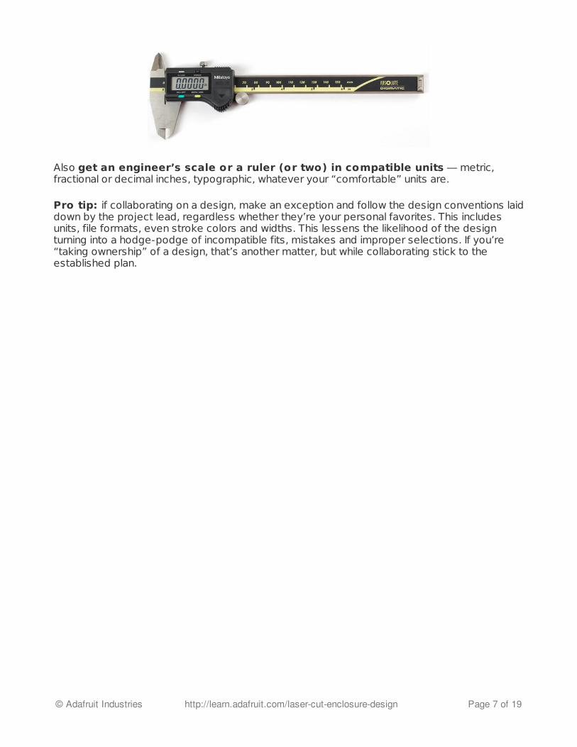
Also get an engineer’s scale or a ruler (or two) in compatible units — metric,fractional or decimal inches, typographic, whatever your “comfortable” units are.
Pro tip: if collaborating on a design, make an exception and follow the design conventions laiddown by the project lead, regardless whether they’re your personal favorites. This includesunits, file formats, even stroke colors and widths. This lessens the likelihood of the designturning into a hodge-podge of incompatible fits, mistakes and improper selections. If you’re“taking ownership” of a design, that’s another matter, but while collaborating stick to theestablished plan.
© Adafruit Industries http://learn.adafruit.com/laser-cut-enclosure-design Page 7 of 19

Materials
When developing a kit enclosure, avoid designs that require glue. It’s messy, mistakescan happen, and there’s no “undo” for customers. Friction-fit parts are one option, but with theslight variability in material thicknesses, we prefer nuts and screws, tabs and slots. T-slots havebecome iconic of laser-cut design, for good reason.
Standardize your component selection. Minimize the inventory of tiny parts. We use#4-40 1/2" screws wherever possible. Metric hex-head screws are way cooler, but bogstandard #4-40 screws are far more readily available at any hardware store in a pinch…andavailable trumps cool. Standardized components also make design go faster, as you’realready intimately familiar with the hardware and its quirks.
We’re so standardized on those screws and nuts, that even for mere prototyping I manage togo through entire boxes of the things. I order these from McMaster-Carr.
After cutting a design, keep a supplyof the larger leftover scrapsaround for cutting other, smaller pieces.Sometimes you just need to iterate onesmall part of an overall design.
Keep a ruler near the scrap box. Ihave one laid across the top of thelasering computer monitor…it’s realhandy for holding up scraps to see if apart will fit within its bounds.
© Adafruit Industries http://learn.adafruit.com/laser-cut-enclosure-design Page 8 of 19

Get to know the local plastics or sign fabrication shop. Buy their scrap as feederstock for developing designs. For these big shops, anything less than a square foot is justwaste to be recycled or discarded, and many will gladly sell it for less than the cost of virgincustom-cut material. You’ll get some truly awful colors sometimes, but that’s half the fun. As abonus…you might even get some small lasering jobs on the side!
1/8" MDF (medium-density fiberboard) is even cheaper as feeder stock, thethickness is very similar to acrylic, and it smells nice when lasering. The burnt edges can bequite sooty though, giving you that chimney sweep look. Not all hardware stores carry thisthickness…I had to scour a few before locating it at Home Depot.
© Adafruit Industries http://learn.adafruit.com/laser-cut-enclosure-design Page 9 of 19

Iteration
Amass a library of reusable parts and dimensions: acrylic thicknesses, T-slotdesigns, mounting hole layouts for Arduino or other boards, etc. After iterating and eventuallynailing a design, you can then carry elements over to new designs without reinventing thewheel each time.
Case in point: I’d found that the ChipKITUno32 (a Microchip PIC32-based Arduinocompatible) had one mounting holeslightly offset from a true Arduino. But anoval-shaped hole could accommodateboth the true and derivative boards.Though I don’t use the Uno32 a whole lot,I still incorporate this same mounting holeset in any new design…the work isalready done, there’s no reason to lockout those boards, and there’s a subsetof users who will appreciate it.
After assembling a prototype, write changes directly on the parts with a Sharpiemarker. Then dismantle and use the notes for the next iteration. Sometimes these are just linesor arrows. This visual representation is quicker and more intuitive to follow than written “moveUSB cutout left 1.5mm” notes. Set aside each sub-part as the changes are made in the design.
Save the parts for each design iteration in a separate Zip-Loc bag in case youneed to refer back to these later (or just as a nice history of your progress). Write “V1”, “V2”,etc. on the outside of each bag (or on a larger front piece inside the bag) to avoid confusion.
Once a design is well-settled upon, it’s okay to discard this history. They’ll fill up your lifeotherwise.
Similarly, save each major iteration in a separate file, perhaps with a sequencenumber like “Foo Case 01”, “Foo Case 02”, etc. Sometimes a direction you take will prove tobe a dead-end, and it’s handy to take a step (or several) back.
Backup software like Time Machine isn’t suitable for this, since it’s based on regular timeintervals, not immediate file changes. Some applications may support a version history…or theversion control systems used in software development (e.g. Git) might be viable; I’ve notexplored this yet as the sequential files have been sufficient to provide a basic “rewind”capability.
After finalizing (you think!) a case design, assemble, disassemble, and reassemble itrepeatedly. Find the optimal path with the clearest explanation and the fewest potentialpitfalls. Then document that one. If it’s just too complicated — if the process can’t becompleted without specialized tools or seven fingers on one hand — consider iterating thedesign again to simplify it.
© Adafruit Industries http://learn.adafruit.com/laser-cut-enclosure-design Page 10 of 19
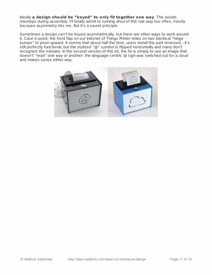
Ideally a design should be “keyed” to only fit together one way. This avoidsmissteps during assembly. I’ll totally admit to running afoul of this rule way too often, mostlybecause asymmetry irks me. But it’s a sound principle.
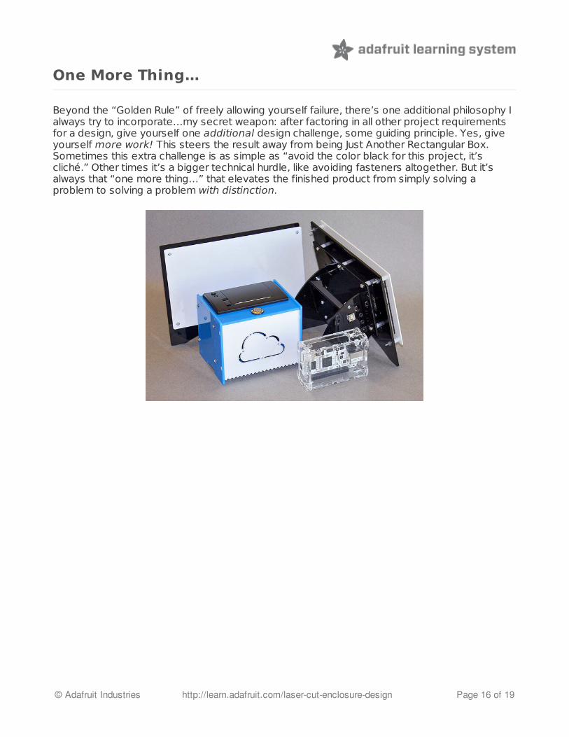
Sometimes a design can’t be keyed asymmetrically, but there are other ways to work aroundit. Case in point: the front flap on our Internet of Things Printer relies on two identical “hingebumps” to pivot upward. It seems that about half the time, users install this part reversed…it’sstill perfectly functional, but the stylized “@” symbol is flipped horizontally and many don’trecognize the mistake. In the second version of this kit, the fix is simply to use an image thatdoesn’t “read” one way or another: the language-centric @ sign was switched out for a cloudand makes sense either way.
© Adafruit Industries http://learn.adafruit.com/laser-cut-enclosure-design Page 11 of 19

Quality
For cost of production (both materials and manpower), the fewer materials orcolors, the better. However, including even a single extra color creates a strongimpression of luxury; it’s no longer “just a box.” Nothing could illustrate this better thanPimoroni’s Pibow case for Raspberry Pi. All those unique layers add up to a lot of productionwork, but people see this and really want it:
For our own Internet of Things Printer, we could have just slapped a plain black front on it andcalled it done…but the “torn receipt” visual pun makes it distinctive. Even when turned off, itimplies the kit’s purpose.
© Adafruit Industries http://learn.adafruit.com/laser-cut-enclosure-design Page 12 of 19
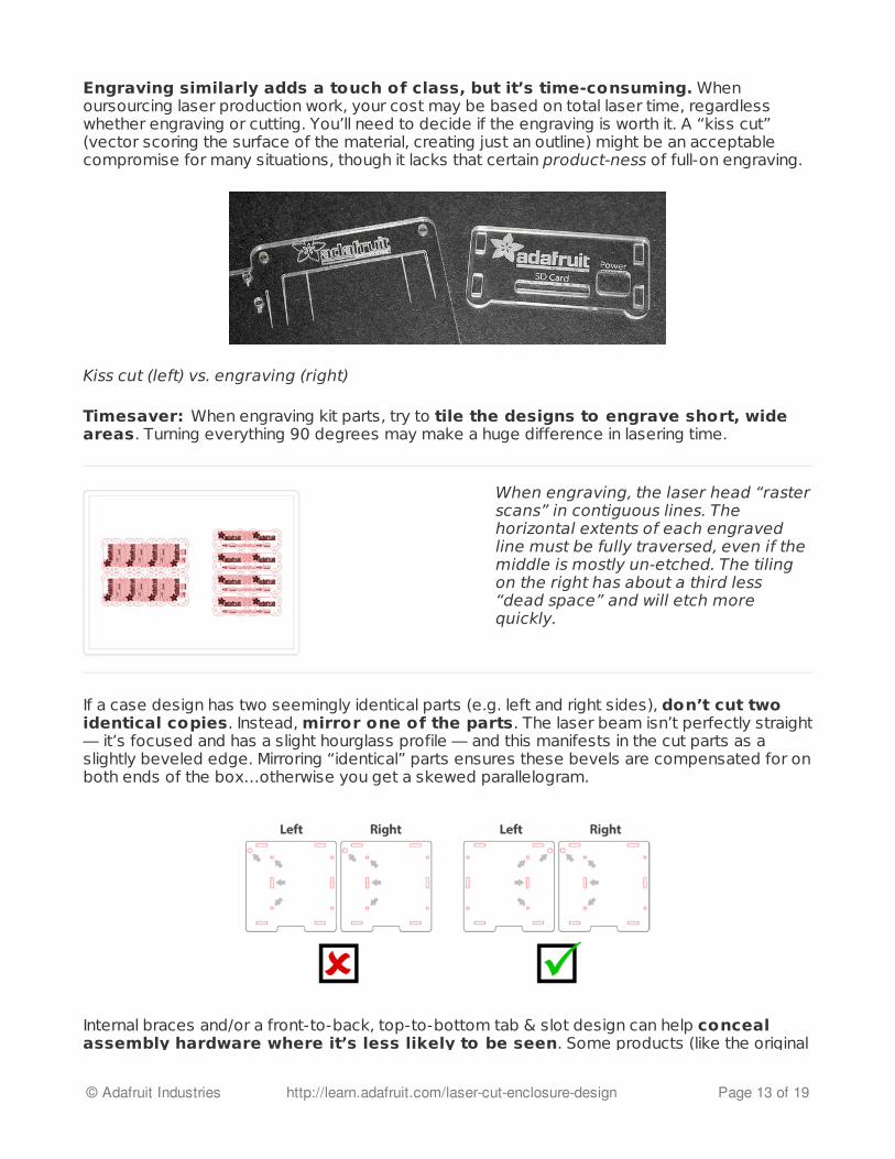
Engraving similarly adds a touch of class, but it’s time-consuming. Whenoursourcing laser production work, your cost may be based on total laser time, regardlesswhether engraving or cutting. You’ll need to decide if the engraving is worth it. A “kiss cut”(vector scoring the surface of the material, creating just an outline) might be an acceptablecompromise for many situations, though it lacks that certain product-ness of full-on engraving.
Kiss cut (left) vs. engraving (right)
Timesaver: When engraving kit parts, try to tile the designs to engrave short, wideareas. Turning everything 90 degrees may make a huge difference in lasering time.
When engraving, the laser head “rasterscans” in contiguous lines. Thehorizontal extents of each engravedline must be fully traversed, even if themiddle is mostly un-etched. The tilingon the right has about a third less“dead space” and will etch morequickly.
If a case design has two seemingly identical parts (e.g. left and right sides), don’t cut twoidentical copies. Instead, mirror one of the parts. The laser beam isn’t perfectly straight— it’s focused and has a slight hourglass profile — and this manifests in the cut parts as aslightly beveled edge. Mirroring “identical” parts ensures these bevels are compensated for onboth ends of the box…otherwise you get a skewed parallelogram.
Internal braces and/or a front-to-back, top-to-bottom tab & slot design can help concealassembly hardware where it’s less likely to be seen. Some products (like the original
© Adafruit Industries http://learn.adafruit.com/laser-cut-enclosure-design Page 13 of 19

MakerBots or our Ice Tube clock (http://adafru.it/194)) just look cool with the hardware allvisible — makers like to see the things they’ve built. But other times we want something morefinished and appliance-like. Unfortunately we can’t hide all the hardware — that’s a limitation oflaser cutting vs. molded enclosures — but with careful design we can minimize the distractions.Tabs and slots are almost unnoticed. Screw heads are a minor distraction. Nuts and T-slots aremuch more unsightly, so try to hide them at the back or on the bottom.
These light cubes — inspired by paperlanterns — use an internal brace (ahidden third plane between the front andback pieces) to conceal their T-slotconstruction. Tabs and screw heads arevisible from the outside, but these aremuch less visually disruptive than hexnuts or T-slots.
The Internet of Things Printer uses asimilar internal brace to keep the top andfront faces smooth and free of industrialprotuberances.
Screw heads are visible only on thesides. T-slots on the back. Nuts on thebottom.
If you can’t hide it…make it obvious! Laser-cut enclosures can’t help but exhibit thattelltale, overlapping-planes appearance, and it can be a challenge to downplay this look.Amanda “w0z” Wozniak’s design for the Monochron clock kit instead exploits the plane edgesas a design element rather than a liability…there’s a hint of Art Deco style or Mission furnitureimplied in this case design.
© Adafruit Industries http://learn.adafruit.com/laser-cut-enclosure-design Page 14 of 19

In some situations you may want to arrange your vector files to cut enclosed shapesfirst (e.g. cut slots and ports before the perimeter of a piece). Depending on the design of thelaser bed, a part may drop down from the material sheet as it’s cut. When this happens, it’srarely a straight drop — the part is now slightly shifted, and any interior cuts will be misaligned.You can usually specify cutting order using different line weights or colors. Not all laser designssuffer this problem though, and the driver software may already take care of cutting enclosedshapes first — a major timesaver!
© Adafruit Industries http://learn.adafruit.com/laser-cut-enclosure-design Page 15 of 19
One More Thing…
Beyond the “Golden Rule” of freely allowing yourself failure, there’s one additional philosophy Ialways try to incorporate…my secret weapon: after factoring in all other project requirementsfor a design, give yourself one additional design challenge, some guiding principle. Yes, giveyourself more work! This steers the result away from being Just Another Rectangular Box.Sometimes this extra challenge is as simple as “avoid the color black for this project, it’scliché.” Other times it’s a bigger technical hurdle, like avoiding fasteners altogether. But it’salways that “one more thing…” that elevates the finished product from simply solving aproblem to solving a problem with distinction.
© Adafruit Industries http://learn.adafruit.com/laser-cut-enclosure-design Page 16 of 19
Case Study: Pi Box
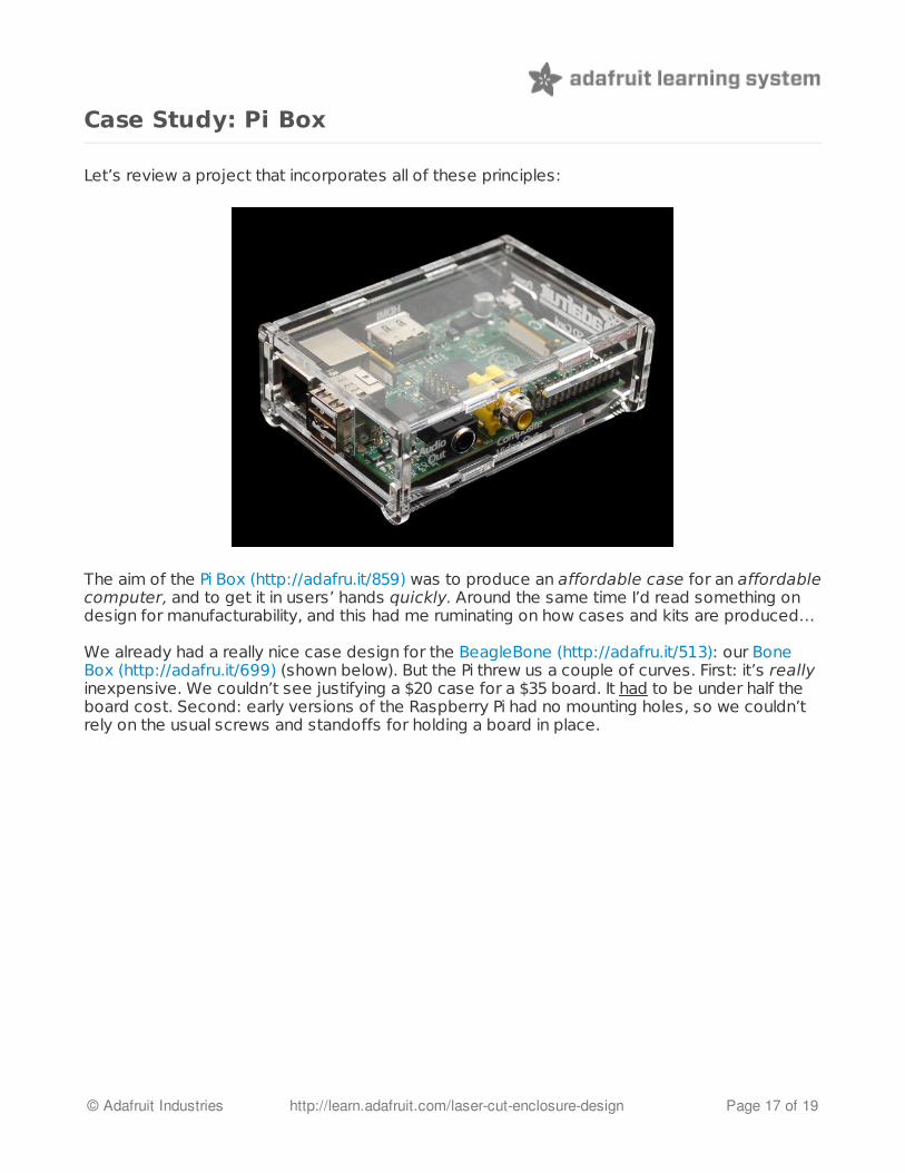
Let’s review a project that incorporates all of these principles:
The aim of the Pi Box (http://adafru.it/859) was to produce an affordable case for an affordablecomputer, and to get it in users’ hands quickly. Around the same time I’d read something ondesign for manufacturability, and this had me ruminating on how cases and kits are produced…
We already had a really nice case design for the BeagleBone (http://adafru.it/513): our BoneBox (http://adafru.it/699) (shown below). But the Pi threw us a couple of curves. First: it’s reallyinexpensive. We couldn’t see justifying a $20 case for a $35 board. It had to be under half theboard cost. Second: early versions of the Raspberry Pi had no mounting holes, so we couldn’trely on the usual screws and standoffs for holding a board in place.
© Adafruit Industries http://learn.adafruit.com/laser-cut-enclosure-design Page 17 of 19

The solutions to both problems are actually related. Much of the expense of an item like thisisn’t in the materials, but the manpower. Kitting — counting, collecting and packaging all theseparate components that make up a kit — takes time. If we could reduce the scope of thisextra hardware-counting step, we could produce a more affordable item than the Bone Box.And then, without any mounting holes on the Pi, we needed to do something differentlyanyway…there was no point to stand-offs here. So, partly for these reasons, and partly as amatter of stubbornness, it became a personal challenge — my one more thing — to developsomething requiring no hardware at all. Six laser-cut acrylic pieces come out of the machineand go in a baggie, and the kit’s done. There’s one small piece that the customer snaps off;this wasn’t fully cut as a separate piece, as fishing out these tiny parts from the laser bed wouldtake more time.
This “simple” box required 23 iterations to get just right. I’d originally tried a number of slotteddesigns, which mostly just fell apart. The idea for the “Dragon Claws,” exploiting the slightflexibility of the acrylic, didn’t come along until about a third of the way through. My favorite part
© Adafruit Industries http://learn.adafruit.com/laser-cut-enclosure-design Page 18 of 19
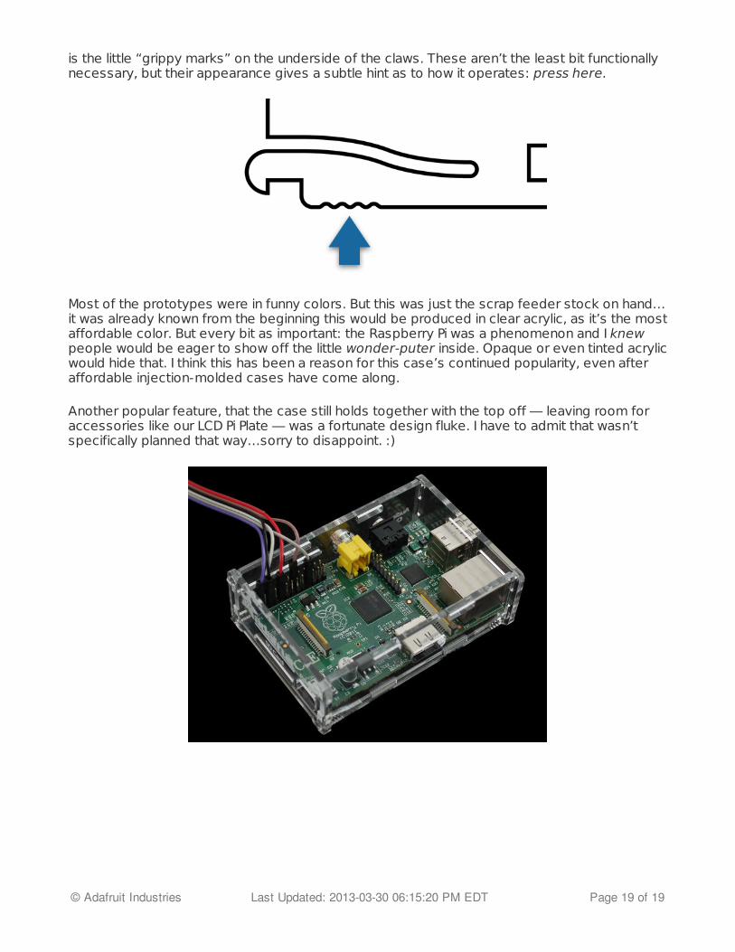
is the little “grippy marks” on the underside of the claws. These aren’t the least bit functionallynecessary, but their appearance gives a subtle hint as to how it operates: press here.
Most of the prototypes were in funny colors. But this was just the scrap feeder stock on hand…it was already known from the beginning this would be produced in clear acrylic, as it’s the mostaffordable color. But every bit as important: the Raspberry Pi was a phenomenon and I knewpeople would be eager to show off the little wonder-puter inside. Opaque or even tinted acrylicwould hide that. I think this has been a reason for this case’s continued popularity, even afteraffordable injection-molded cases have come along.
Another popular feature, that the case still holds together with the top off — leaving room foraccessories like our LCD Pi Plate — was a fortunate design fluke. I have to admit that wasn’tspecifically planned that way…sorry to disappoint. :)
© Adafruit Industries Last Updated: 2013-03-30 06:15:20 PM EDT Page 19 of 19