laser audio transmission project · 2012-11-09 · (hene) laser, if hn08m (p/n if 511), or a...
TRANSCRIPT

Laser Audio Transmission Project
Experiment & Product Guide IF 511 and IF 512
INDUSTRIAL FIBER OPTICS

*
Copyright © 2010 Previous Printings 2000, 2003, 2006
by Industrial Fiber Optics, Inc. Revision - C
Printed in the United States of America
* * *
All rights reserved. No part of this publication may be reproduced, stored in a retrieval system, or transmitted in any form or by any means (electronic, mechanical, photocopying, recording, or otherwise) without prior written
permission from Industrial Fiber Optics, Inc.
* * * * *

- i -
Introduction
This manual provides information about Industrial Fiber Optics' Laser Audio
Transmission Project. The project can be purchased with either a Helium Neon
(HeNe) laser, IF HN08M (P/N IF 511), or a Semiconductor Diode laser, IF RL08-635
(P/N IF 512), as the laser light transmission source. The manual contains all the
information you need for both lasers to complete this project safely and
knowledgeably, even if you are a novice to this technology. Please read the manual
carefully while completing activities.
As soon as you receive the Laser Audio Transmission Project, inspect it and the
shipping container for damage. If any damage is found, immediately refer to the
section of this manual entitled "Shipment Damage Claims". Then check the contents
against the appropriate kit listed in Table 1.
Industrial Fiber Optics makes every effort to incorporate state-of-the-art
technology, highest quality and dependability in its products. We constantly explore
new ideas and products to best serve the rapidly expanding needs of industry and
education. We encourage comments that you may have about our products, and we
welcome the opportunity to discuss new ideas that may better serve your needs. For
more information about our company and products refer to http//www.i-
fiberoptics.com on the Worldwide Web.
Thank you for selecting this Industrial Fiber Optics product. We hope it meets
your expectations and provides many hours of productive activity.
Sincerely,
The Staff at Industrial Fiber Optics

- ii -

- iii -
TABLE OF CONTENTS
Introduction .................................................................................... i
LASER CLASSIFICATIONS..................................................... iv
PROJECT KIT COMPONENTS................................................ 1
LIGHT for COMMUNICATION.................................................. 2
ACTIVITIES
HeNe Procedure ..................................................................... 3 Diode laser Procedure ............................................................ 5 Fiber Optic Procedure ............................................................. 7
TROUBLESHOOTING............................................................... 8
SERVICE AND MAINTENANCE ............................................. 9
WARRANTY .............................................................................. 10
SHIPMENT DAMAGE CLAIMS ................................................ 11

- iv -
LASER CLASSIFICATIONS
All manufacturers of lasers used in the United States must conform to regulations administered by the Center for Devices and Radiological Health (CDRH), a branch of the U.S. Department of Health and Human Services. CDRH categorizes lasers as follows:
Class Description
I A laser or laser system which does not present a hazard to skin or eyes for any wavelength or exposure time. Exposure varies with wavelength. For ultraviolet, .2 to .4 !m exposure is less than from .8 nW to .8 !W. Visible light exposure varies from .4 !W to 200 !W, and for near IR, the exposure is < 200 !W. Consult CDRH regulations for specific information.
II Any visible laser with an output less than 1 mW of power. Warning label
requirements — yellow caution label stating maximum output of 1 mW. Generally used as classroom lab lasers, supermarket scanners and laser pointers.
IIIa Any visible laser with an output over 1 mW of power with a maximum output of 5 mW of power. Warning label requirements — red danger label stating maximum output of 5 mW. Also used as classroom lab lasers, in holography, laser pointers, leveling instruments, measuring devices and alignment equipment.
IIIb Any laser with an output over 5 mW of power with a maximum output of 500 mW of power and all invisible lasers with an output up to 400 mW. Warning label requirements — red danger label stating maximum output. These lasers also require a key switch for operation and a 3.5-second delay when the laser is turned on. Used in many of the same applications as the Class IIIa when more power is required.
IV Any laser with an output over 500 mW of power. Warning label requirements — red danger label stating maximum output. These lasers are primarily used in industrial applications such as tooling, machining, cutting and welding. Most medical laser applications also require these high-powered lasers.

- 1 -
Project Kit Components
Table 1 lists all components included in both models of the Laser Audio Transmission Kit. Before proceeding to activities, identify each component listed in the table below for the appropriate kit number.
Table 1. Project kits component lis t .
General Description P/N IF 511
P/N IF 512
Quantity
Laser Audio Receiver IF 513 IF 513 1
Helium Neon (HeNe)
Laser
IF HN08M 1
Diode Laser IF RL08-635 1
Microphone 57 0022 57 0022 1
Plastic Optical Fiber IF C E1000 IF C E1000 3 meters
After inspecting your kit for the correct contents you can proceed to set up a voice transmission project. Go to page 3 if you have the helium neon laser project and to page 5 if you have the semiconductor laser project.
Table 2. Common abbreviations used in this manual .
Abbr. Long version Scientific Notation
mW milliwatts 1 x 10⁻³
watts
!W microwatts 1 x 10⁻⁶
watts
nW nanowatts 1 x 10⁻⁹
watts
mm millimeters 1 x 10⁻³
meters
!m micrometers 1 x 10⁻⁶
meters
nm nanometers 1 x 10⁻⁹
meters

- 2 -
Light as Communication
Light is usually thought of as a modern means of communication, be it line of sight directly from source to receiver or through a medium such as a fiber optic cable. However, light has been used to provide communications since ancient times.
One of the earliest recorded uses of light for communications comes from the ancient city of Alexandria. One of the 7 wonders of the ancient world was the Pharos Lighthouse constructed around 290 BC. This impressive structure towered over the city and provided guidance for sailors at sea as far as 35 miles. It used a mirror to reflect sunlight during the day and bonfires at night to guide ships to the harbor.
Moving forward historically, the advent of modern communications with light can be said to have started with Alexander Graham Bell. In addition to the telephone this prolific inventor created what he called the photophone. Utilizing sunlight reflected from mirrors Mr. Bell generated the worlds first wireless telephone call on June 3, 1880. He considered this an even greater invention than the telephone, and the ever growing field of fiber optic communications pays tribute to his belief that light was the communication method of the future.

- 3 -
HeNe Laser Procedure
Equipment Needed:
• HeNe Laser ; IFO part number IF HN08
• 120-VAC to 12-VDC powe adapters (2)
• Microphone; IFO part number 57 0022
• Laser Audio Receiver; IFO part number IF 513
Procedure:
1. Choose a flat, level surface about 60 x 120 cm (2 x 4 feet) in size.
2. Collect all the items listed in the “EQUIPMENT NEEDED” section above.
3. Review the Rules for Laser Safety listed on the back cover of this booklet.
4. For detailed information regarding the operation of the helium neon laser refer to its operating manual.
5. Position the laser and the receiver as shown in Figure 1.
6. Push the laser shutter’s handle downward to its closed position.
7. Make sure the laser's ON/OFF switch (SW) is in its OFF position. (The push button should be in its extended position.)
audioreceiver
laser
Figure 1. Side view of the laser and audio receiver.
8. Plug the VAC-to-DC laser power adapter into an AC electrical outlet.
9. Plug the cord from the power adapter into the power jack (PWR) located on the rear of the laser.
10. Plug the VAC-to-DC audio receiver power adapter into an AC electrical outlet.
11. Plug the cord from the power adapter into the power jack located on the front of the audio receiver.
12. Plug the microphone into the 3.5 mm audio jack on the back of the laser.

- 4 -
13. Depress the ON/OFF switch (SW) on the control panel of the laser until it clicks into the ON position. (The switch should be slightly depressed.) The pilot light (green LED) on the laser should now be lit, showing that it is on.
14. Open the laser shutter.
15. Dim the room lights to help you observe the laser beam. Position the receiver in line with the laser so the beam strikes the audio receiver close to the photodetector access hole. Manually align the beam with the optical input (photo diode) of the audio receiver.
16. Turn on the microphone using the switch located on the side.
17. Turn the ON/OFF volume knob on the audio receiver to the 12 o’clock position. The pilot light (yellow LED) on the audio receiver should now be lit, showing that it is on.
18. Speak into the microphone and listen for your voice to come out of the audio receiver. If you do not hear your voice on the first attempt, continue to speak into the microphone while turning up the volume control clockwise on the audio receiver. If you reach maximum volume and still do not hear your voice, realign the laser beam with the audio receiver while speaking into the microphone.
19. When you have the audio receiver and the laser properly aligned you should easily hear your voice from the receiver when you speak into the microphone.
20. If you continue to have problems at this point refer to the “TROUBLESHOOTING” section in the back of the manual. If you have successfully established an audio link using the laser continue with your experiment.
21. Upon completing the experiment close the laser beam shutter. At this time you can either continue to the Fiber Optic Transmission procedure on page 7 or switch off the laser and complete the remaining steps below.
22. Turn the volume knob on the audio receiver to the OFF position.
23. Turn off the microphone.
24. Unplug the power adapters from the electrical outlets, the laser and the audio receiver.
25. Remove all equipment from the table and store in their proper locations.
Direct Laser Beam through hole and
onto detector
1515.eps
Figure 2. Close up
view of the alignment laser
beam to receiver aperture .

- 5 -
Diode Laser Procedure
Equipment Needed:
• Diode Laser; IFO part number IF RL08-635
• 120 -VAC to 12-VDC power adapter (2)
• Microphone; IFO part number 57 0022
• Laser Audio Receiver; IFO part number IF 513
Procedure:
1. Choose a flat, level surface about 60 x 120 cm (2 x 4 feet) in size.
2. Collect all the items listed in the “EQUIPMENT NEEDED” section above.
3. Review the Rules for Laser Safety listed on the back cover of this booklet.
4. For detailed information regarding the operation of the semiconductor diode laser refer to its operating manual.
5. Position the laser and the receiver as shown in Figure 3.
6. Push the laser shutter’s handle downward to its closed position.
7. Make sure the laser's ON/OFF switch (SW) is in its OFF position. (The push button should be in its extended position.)
audioreceiver
laser
Figure 3. Side view of the laser and audio rece iver.
8. Plug the VAC-to-DC laser power adapter into an AC electrical outlet.
9. Plug the cord from the power adapter into the power jack (PWR) located on the rear of the laser.
10. Plug the VAC-to-DC audio receiver power adapter into an AC electrical outlet.
11. Plug the cord from the power adapter into the power jack located on the front of the audio receiver.
12. Plug the microphone into the 3.5 mm audio jack on the back of the laser.
Direct Laser Beam through hole and
onto detector
1515.eps
Figure 4. Close up
view of the alignment laser
beam to receiver aperture.

- 6 -
13. Depress the ON/OFF switch (SW) on the control panel of the laser until it clicks into the ON position. (The switch should be slightly depressed.) The pilot light (green LED) on the laser should now be lit, showing that it is on.
14. Adjust the Gain Control knob on the laser to the fully counter-clockwise position. (Gain = 1)
15. Open the laser shutter.
16. Dim the room lights to help you observe the laser beam. Position the receiver in line with the laser so the beam strikes the audio receiver around the photodetector access hole. Manually align the beam with the optical input (photo diode) of the audio receiver.
17. Turn on the microphone using the switch located on the side.
18. Turn the ON/OFF volume knob on the audio receiver to the 12 o’clock position. The pilot light (yellow LED) on the audio receiver should now be lit, showing that it is on.
19. Speak into the microphone and listen for your voice to come out of the audio receiver. If you do not hear your voice on the first attempt, continue to speak into the microphone while turning up the volume control clockwise on the audio receiver. If you reach maximum volume and still do not hear your voice, realign the laser beam with the audio receiver while speaking into the microphone.
20. When you have the audio receiver and the laser properly aligned you should hear your voice from the receiver when you speak into the microphone. If you do not slowly adjust the Gain Control knob clockwise while continuing to speak into the microphone. (Maximum gain = 50 at the full clockwise position)
21. If you continue to have problems at this point refer to the “TROUBLESHOOTING” section in the back of the manual.
22. Upon completing the experiment close the laser beam shutter. At this time you can either continue to the Fiber Optic Transmission procedure on next page or switch off the laser and complete the remaining steps below.
23. Turn the volume knob on the audio receiver to the OFF position.
24. Turn the Gain Control knob fully counter-clockwise and turn off the microphone.
25. Unplug the power adapters from the electrical outlets, the laser and the audio receiver.
26. Remove all equipment from the table and store in their proper locations.
Fiber Optic Transmission Procedure
Additional Equipment Needed:
3 meters 1.0 mm core plastic optical fiber
- 7 -
Procedure:
The assumption is made that one of the proceeding laser procedures is still set up and operational as an optical audio link, and you are now familiar with the safe operation of the laser. It is recommended that 2 people be used for this procedure to simplify the handling of the equipment and the fiber. If you need to do this experiment by yourself it is recommended that the microphone be replaced as the audio input source with a radio or other device to provide the modulation for the laser. This will allow the use of both hands to handle the plastic optical fiber.
If you are starting this procedure as a new stand alone experiment please refer to the initial set-up steps, up to the point of turning on the laser, for the project kit that was purchased. The intent of this procedure is to show how optical fiber is used as a waveguide for light so that a straight line of sight from the sending point to the receiver is no longer required.
1. Move the audio receiver out of the laser path.
2. Grasp one end of the fiber optic cable between your thumb and forefinger. Open the shutter of the laser and hold the fiber in the path of the laser beam (input side). DO NOT LOOK AT THE OUTPUT END OF THE FIBER AT
THIS TIME.
3. Have a second person grasp the other end of the fiber optic cable (output side) and hold it up to the optical input, (photo diode) of the audio receiver.
4. Speak into the microphone and listen to hear your voice coming from the audio receiver. If your voice is not heard increase the volume slowly until maximum volume is reached. If you still do not hear your voice check to see that the fiber is aligned with the laser beam and is being transmitted through the fiber to strike the optical input photo diode. DO NOT LOOK DIRECTLY
AT THE OUTPUT END OF THE FIBER. Hold the fiber end up to a white sheet of paper to verify beam transmission.
5. If you continue to have problems at this point refer to the “TROUBLESHOOTING” section in the back of the manual. If you have successfully established an audio link using the plastic optical fiber continue with your experiment.
6. Once the procedure is completed turn off all equipment and return the equipment to its appropriate storage location.

- 8 -
TROUBLESHOOTING
NO PILOT LIGHT
• Is the laser’s ON/OFF switch in the ON position?
• Is the 110 (220) VAC-to-VDC power adapter plugged into the laser and an appropriate wall outlet or extension cord?
• Is there power to the wall outlet?
NO LIGHT OUTPUT FROM LASER
• Check pilot light. If not on, go to the previous Troubleshooting step.
• Is the mechanical beam stop in its open position?
• Damaged or inadequate power adapter.
• Low voltage to the wall outlet.
NO SOUND FROM LASER AUDIO RECEIVER
• Is the 110 (220) VAC-to-VDC power adapter plugged into the laser audio receiver and an appropriate wall outlet or extension cord?
• Is the receiver’s power indicator light on?
• Is the laser beam positioned properly so its beam hits the receiver detector?
• Are input signals to the laser of sufficient amplitude? (Speak louder into the microphone.)
• For Diode Laser Only: Check to see if the Gain control knob is turned to the 12 o’clock position (refer to the Laser Diode instruction manual for the operation of the Gain Control knob).
• Check for damaged or open electrical circuit in the microphone cord.
• Slowly turn down the volume control on the receiver while continuing to talk into the microphone. (This will desensitize the receiver in case the receiver is too sensitive [saturating] for this laser.)
• Check the troubleshooting section in your laser audio receiver manual.
Do not attempt to troubleshoot the laser or laser receiver beyond the steps listed above. If all your connections are correct, and you are confident that power is being supplied to the laser and any input devices, please return the laser for appropriate inspection/servicing to Industrial Fiber Optics, as described in the section entitled “SERVICE AND MAINTENANCE”.
- 9 -
SERVICE AND MAINTENANCE
Periodic operation, maintenance and service of this equipment is not required. The warranty will be voided if entry has been made, and/or any screws have been removed.
In the unlikely event this equipment malfunctions and you wish to have it repaired, please do the following:
• In writing, describe the problem, person to contact, phone number, and return address.
• Carefully pack the item, its power adapter, manual, and written description in a stout box with sufficient packing material to prevent damage in shipment.
• Ship the package to:
INDUSTRIAL FIBER OPTICS
1725 West 1st Street Tempe, AZ 85281-7622 USA
- 10 -
WARRANTY
Industrial Fiber Optics products are warranted against defects in materials and workmanship. The warranty for the product, excluding laser, is for one (1) year. The warranty for the individual laser is dependent upon model. Refer to the manual which was included with the laser for the proper warranty period. The warranty will be voided if internal or external components have been damaged, mishandled, or altered by the buyer.
Warranty liability is limited to repair or replacement of any defective unit at the company's facilities, and does not include attendant or consequential damages. Repair or replacement can be made only after failure analysis at the factory. Authorized warranty repairs are made at no charge, and are guaranteed for the balance of the original warranty.
Industrial Fiber Optics will pay the return freight and insurance charges for warranty repair within the continental United States, by United Parcel Service or Parcel Post. Any other delivery means must be paid for by the customer.
If an item is not under warranty, repairs will not be undertaken until the cost of such repairs have been prepaid by the customer. Typical repair costs range from $25 - $75, and completion times from two to three weeks.
When returning items for analysis and possible repair, please do the following:
• In a letter, describe the problem, person whom we should contact, phone number, and return address.
• Pack the warranted item and your letter carefully in a strong box with adequate packing material, to prevent damage in shipment.
• Ship the package to:
INDUSTRIAL FIBER OPTICS
1725 West 1st Street Tempe, AZ 85281-7622 USA
- 11 -
SHIPMENT DAMAGE CLAIMS
If damage to an Industrial Fiber Optics product should occur during shipping, it is imperative that it be reported immediately, both to the carrier and the distributor or salesperson from whom the item was purchased. DO NOT CONTACT INDUSTRIAL FIBER OPTICS.
Time is of the essence because damage claims submitted more than five days after delivery may not be honored by the carrier. If damage has occurred during shipment, please do the following:
• Make a note of the carrier company; the name of the carrier employee who delivered the damaged product; the date; and the time of the delivery.
• Keep all packing material.
• In writing, describe the specific nature of damage to the product.
• In cases of severe damage, do not attempt to use the product, install batteries, or connect any other power source.
• Notify the carrier immediately of any damaged product.
• Notify the distributor from whom the purchase was made.
------------------------------
- 12 -
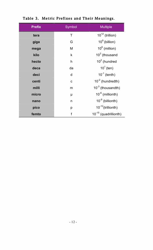
Table 3. Metric Prefixes and Their Meanings .
Prefix Symbol Multiple
tera T 1012
(trillion)
giga G 109
(billion)
mega M 106 (million)
kilo k 103 (thousand
hecto h 102 (hundred
deca da 101
(ten)
deci d 10-1
(tenth)
centi c 10-2
(hundredth)
milli m 10-3
(thousandth)
micro ! 10-6
(millionth)
nano n 10-9
(billionth)
pico p 10-12
(trillionth)
femto f 10-15
(quadrillionth)


12 0130
Rules for Laser Safety
• Lasers produce a very intense beam of light. Treat them with respect. Most educational lasers have an output of less than 3 milliwatts, and will not harm the skin.
• Never look into the laser aperture while the laser is turned on. PERMANENT EYE
DAMAGE COULD RESULT.
• Never stare into the oncoming beam. Never use magnifiers (such as binoculars or telescopes) to look at the beam as it travels — or when it strikes a surface.
• Never point a laser at anyone's eyes or face, no matter how far away they are.
• When using a laser in the classroom or laboratory, always use a beam stop, or project the beam to areas which people won't enter or pass through.
• Never leave a laser unattended while it is turned on — and always unplug it when it's not actually being used.
• Remove all shiny objects from the area in which you will be working. This includes rings, watches, metal bands, tools, and glass. Reflections from the beam can be nearly as intense as the beam itself.
• Never disassemble or try to adjust the laser's internal components. Electric shock could result.