laser additive manufactured wc reinforced fe-based...
TRANSCRIPT

Contents lists available at ScienceDirect
Composite Structures
journal homepage: www.elsevier.com/locate/compstruct
Laser additive manufactured WC reinforced Fe-based composites withgradient reinforcement/matrix interface and enhanced performance
Dongdong Gua,b,⁎, Ji Maa,b, Hongyu Chena,b, Kaijie Lina,b, Lixia Xia,b
a College of Materials Science and Technology, Nanjing University of Aeronautics and Astronautics, Yudao Street 29, Nanjing 210016, Jiangsu Province, PR Chinab Jiangsu Provincial Engineering Laboratory for Laser Additive Manufacturing of High-Performance Metallic Components, Nanjing University of Aeronautics andAstronautics, Yudao Street 29, Nanjing 210016, Jiangsu Province, PR China
A R T I C L E I N F O
Keywords:Laser additive manufacturingMetal-matrix composite (MMCs)Gradient interfaceMechanical performance
A B S T R A C T
Laser additive manufacturing has been proved to be a new technology for production of high-performance metalmatrix composites with tailored interfacial structures. The WC particle reinforced Fe-based composites weremanufactured by selective laser melting to investigate the effects of laser processing parameters on densification,microstructure and mechanical properties. The densification level increased with increasing laser power anddecreasing scanning speed. The novel gradient interface formed around WC particles due to the in-situ reactionbetween WC particle and Fe-based matrix. After the optimization of laser processing conditions, the micro-hardness enhanced to 511.6 HV0.2 and a low friction coefficient of 0.30 was achieved with a low wear rate of3.1× 10−5 mm3/(Nm). The improvement in wear performance attributed to the synergistic effect of gradientinterface, enhanced densification and novel microstructure.
1. Introduction
Laser additive manufacturing (LAM), as an advanced manufacturingtechnology, enables the direct manufacture of arbitrary components forsmall batches, which possessed unique structures or complex shapes,and is used for the fabrication of functional materials in recent years[1–5]. As an inspiring technology of LAM, selective laser melting (SLM)can completely melt metals and alloys with high melting point to reachhigher internal density. In addition, compared with previous LAMmethods, the laser focused spot size of SLM is smaller, leading to ahigher dimensional precision and better surface integrity, thus savingtime for post-processing. Due to the its advantages, SLM has beenwidely used to process various materials such as Ti-based alloy [6–9],Ni-based superalloy [10], Al-based alloy [11–13] and Fe-based alloy[14–16].
Due to the adequate resources and excellent mechanical properties,Fe-based alloys (or alloy steel) exert an irreplaceable role from industryapplication to daily life, becoming the most widely used metal in var-ious science and industry fields. Nevertheless, with the development ofindustry technology, it brings forward an increasing demand for ma-terials comprehensive performance and the single Fe-based alloy nolonger meets the challenge. Metal matrix composites (MMCs), com-bined metallic properties with ceramic, have been fabricated by
different manufacturing methods and investigated widely in recentyears [17–20]. Similarly, reinforced by ceramic particulates, the per-formance of Fe-based composites can also be greatly improved. How-ever, Fe-based composites processed by conventional methods usuallyhave poor density, weak strength and high cracking susceptibilitycaused by poor wettability and large residual stress owing to thecoefficient of thermal expansion mismatch between reinforcing parti-cles and matrix, which may lead to cracks, seriously affecting the me-chanical performance. In order to solve these problems, many re-searchers have tried to introduce laser processing methods to fabricateFe-based composites [21–23]. It was reported that the thin particle/matrix interface formed using laser processing methods can promoteinterfacial bonding and stress transferring, leading to adjust differentdistortion mechanism between reinforcement and matrix during me-chanical loading [24,25]. As a kind of structural material, reinforcingwith ceramic particles is an effective method to improve wear re-sistance for Fe-based alloy and there have been many explorations inthis filed [21,25]. It is apparent that the combination between re-inforcement and matrix is important in improving wear resistance, sothe interface may play an important role.
WC is considered as a good ceramic reinforcement phase because ofits high melting point and good wettability with Fe-based alloy [26].Moreover, WC can retain its room temperature hardness up to 1400 °C.
https://doi.org/10.1016/j.compstruct.2018.03.008Received 26 July 2017; Received in revised form 26 January 2018; Accepted 7 March 2018
⁎ Corresponding author at: College of Materials Science and Technology, Nanjing University of Aeronautics and Astronautics, Yudao Street 29, Nanjing 210016, Jiangsu Province, PRChina.
E-mail address: [email protected] (D. Gu).
Composite Structures 192 (2018) 387–396
Available online 08 March 20180263-8223/ © 2018 Elsevier Ltd. All rights reserved.
T

Therefore, in this research, WC was selected as the reinforcement ma-terial to form Fe-based metal matrix composite via selective lasermelting. The growth mechanism of gradient interfacial layer betweenWC particle and Fe-based alloy matrix within WC/Fe-based compositeparts was studied. The effects of the processing parameters on the mi-crostructures and mechanical properties of SLM-processed WC/Fe-based composites including densification, microhardness and wearproperties at room temperature were analyzed.
2. Experiment procedures
2.1. Powder preparation
The raw materials used were the gas atomized, spherical Fe-basedalloy powder with the size distribution of 5–30 μm (the chemicalcompositions are shown in Table 1), and the polygonal reinforcing WCparticle with the equivalent spherical size distribution of 5–15 μm(Fig. 1(a)). The two categories of powder, with the weight ratio of WC:Fe-based alloy=1:3, were mixed homogeneously in a Pulverisette 6planetary ball mill (Fritsch GmbH, Germany) at a rotation speed of200 rpm for 4 h. After ball milling, the WC particles were disperseduniformly in the powder mixture, as shown in Fig. 1(b) and (c).
2.2. SLM process
The SLM system used in this work is developed by NanjingUniversity of Aeronautics and Astronautics (NUAA). The system con-sists of an IPG Photonics Yitterbium YLR-500-WC fiber laser with amaximal laser power of 500W and a laser spot diameter of 70 μm, aninert Ar gas protection system, an automatic powder layering systemand a computer control system (Fig. 2(a)). The laser processing para-meters were set up as follows: hatch space of 70 μm, layer thickness of50 μm, laser power (P) of 78, 89 and 100W, and scanning speeds (v) of200, 300, 400 and 500mm/s. The WC reinforced Fe-based compositespecimens were manufactured with the dimension of5mm×5mm×5mm (Fig. 2(b)).
2.3. Microstructure observation
The cubic samples of WC reinforced Fe-based composite fabricatedby SLM were cut from the substrate, then were ultrasonically cleaned inethanol and dried for the following analysis. The samples were groundand polished following standard metallographic procedures, and etchedwith a solution consisting of HNO3 (4mL) and anhydrous alcohol(96mL) for metallographic examinations.
A PMG3 optical microscope (OM; Olympus Corporation, Japan) wasutilized to observe the densification behavior of the samples and themorphology of the molten pool under low magnification. The micro-structures of samples were characterized using a field emission scan-ning electron microscope (FE-SEM; Hitachi S-4800, Japan) and thechemical composition was determined by energy dispersive X-rayspectroscope (EDX; EDAX Inc., USA).
Table 1Chemical compositions of Fe-based alloy powder.
Element Fe C Cr Ni Mo Mn Si P S
Content(wt.%)
Balance 0.45 1.35 4.0 0.25 0.40 0.25 ≤0.025 ≤0.025
Fig. 1. Morphologies of the starting powder materials: (a) WC particles; (b) the homogeneously mixed 25 wt% WC reinforced Fe-based alloy powder; (c) High-magnification image ofmixed 25 wt% WC reinforced Fe-based alloy powder (BSE mode).
D. Gu et al. Composite Structures 192 (2018) 387–396
388

2.4. Characterization of mechanical properties
The relative density of SLMed WC reinforced Fe-based compositesamples was calculated by the ratio of actual density and theory den-sity. The actual density was measured according to Archimedes prin-ciple and the theoretical density was calculated according to the rule ofmixtures. The macrohardness of samples was measured on the polishedcross-sections using a HXS-1000A macrohardness tester (AMETEK,China) with 200 g loading and 15 s dwell time. Dry sliding wear testswere carried out using a HT-500 ball-on-disk tribometer with a 3mm-diameter Si3N4 bearing ball as the counterpart under a load of 630 g atroom temperature in a laboratory environment. The sample wasmounted on a stage of rotation in the ball-on-disk configuration, whilethe ball on which a known force was applied was contacted with thesample to cause wear. The rotating speed was 560 rpm and the rotationradius was set to be 1mm during the tests. The coefficient of friction(COF) was recorded for 15min. The morphologies of the worn surfaceof the SLM-processed samples under various processing parameterswere observed by SEM. The wear rates (ω) were calculated by the fol-lowing equations [29]:
=ω V WL/( ) (1)
=V M ρ/loss (2)
where V is the volumetric loss of sample during wear tests, W is thecontact load, L is the sliding distance, and Mloss is the loss weight of thesamples, ρ is the density.
3. Results and discussion
3.1. Densification behavior and dispersion of reinforcement particles
Fig. 3(a) depicts the relative density of SLMed WC reinforced Fe-based composite parts under different laser parameters. It can be seenthat the relative densities were intimately related to laser power andlaser scanning speed. Under a certain laser power, the densification wason a downward trend along with the increase of laser scanning speed.The highest relative densities of samples under each laser power wereobtained at scanning speed of 200mm/s, measured as 97.5% (78W),97.9% (89W) and 98.5% (100W) respectively. And under a certainscanning speed, the relative density increased with the increase of laserpower, and reached the highest value at the laser power of 100W.
Fig. 3(b) lists all laser processing parameters used in this experi-ment, and all samples were separated into four groups according to thelevel of densification. The relative density of red area is higher than97%; the blue area is between 93.5% and 97%; the green area is be-tween 90% and 93.5%; the black area is lower than 90%. In order tostudy the effect of laser processing parameters on densification beha-vior, one sample from each area was selected for further investigation.The parameters of four samples are as follows: (a) P=78W,v=200mm/s; (b) P=78W, v=300mm/s; (c) P=78W,v=400mm/s; (d) P=78W, v=500mm/s. The etched cross-sectionsof SLMed WC reinforced Fe-based composite samples under differentprocessing parameters were shown in Fig. 4. It can be seen that thedensification behavior, molten pool morphology and layerwise micro-structure varied with parameters. When laser power was set as 78Wand a relatively low scanning speed of 200mm/s was applied, a densesection free of any pore with the densification of 97.5% was obtained,showing a homogenous layerwise microstructure, which achieved a
Fig. 2. (a) Schematic diagram of SLM process; (b) SLM-processed WC reinforced Fe-based composite samples by under various processing parameters.
Fig. 3. (a) Variation of relative density of SLM-processed WC reinforced Fe-based composite samples at different laser processing parameters. (b) A process window of SLM-processed WCreinforced Fe-based composite samples.
D. Gu et al. Composite Structures 192 (2018) 387–396
389

good metallurgical bonding between adjacent layers and scanningtracks (Fig. 4(a)). At a higher scanning speed of 300mm/s, the layer-wise microstructure was still homogeneous, and continuous and stablemolten pools can be observed visibly. But some nearly orbicular mi-cropores were formed and dispersed between the neighboring scanningtracks and layers (Fig. 4(b)). In this instance, the densification ap-proached 93.8%. When the scanning speed increased to 400mm/s, themolten pool morphology became unclear and the distribution of layerswas uneven. In addition, larger-sized pores with irregular shape whichcrossed several layers were clearly observed (Fig. 4(c)), leading thedensification response by merely 91.7%. At an even higher scanningspeed of 500mm/s, more irregular interlayer pores were formed, re-sulting in a reduced densification of 86.5%. At the same time, the dis-tribution of molten pools exhibited heterogeneous, leading to an un-even layerwise microstructure, which would exert a negative impact oninterlayer bonding (Fig. 4(d)).
The variation of relative density with laser power and scanningspeed can be attributed to the dynamic viscosity of liquid phase andsubsequent liquid flowability and wettability. During SLM process, themixture powder was irradiated by the laser beam and started to melt.Owing to the lower melting point compared to WC powder, the Fe-based alloy powder was melted firstly, forming a moving molten pool.Meanwhile, WC particles dissolved partly in the melted Fe-based alloythough its melting point was pretty high. Accordingly, the dissolution ofWC particles increased the viscosity of the melt, restricting the flow-ability of the melt. The dynamic viscosity (μ) of the composite melt canbe calculated as follows [30]:
=μγ m
k T1615 B (3)
where γ is the surface tension of the melt, m is the atomic mass, and kBis the Boltzmann constant, T is the temperature of molten pool. The Eq.(3) illustrates that the viscosity is highly temperature-dependent. Whena low laser power or high scanning speed is applied, the energy thatmaterial received per unit time is insufficient, leading to low moltenpool temperature. That will increase the viscosity of melt, hence re-ducing the wettability. In this case, the melt cannot spread adequately
on the underlying solidification layer, resulting in the emergence ofirregular interlayer pores. As a consequence, the densification of spe-cimen is limited. Under a constant laser scanning speed, higher laserpower caused more energy input into powder materials, leading to ahigher temperature in the molten pool. The viscosity of melt will de-crease and flowability and wettability will become better, contributingto higher densification. When laser power is constant, with the decreaseof scanning speed, powder can absorb more energy per unit time, andtemperature of melt will increase, causing low viscosity and betterwettability of melt. Consequently, densification will increase [31]. Onthe other hand, the decrease of scanning speed extend the lifetime ofmolten pool so that the melt has enough time to wet the underlyinglayer to reduce the porosity of sample.
3.2. Gradient interface and microstructure
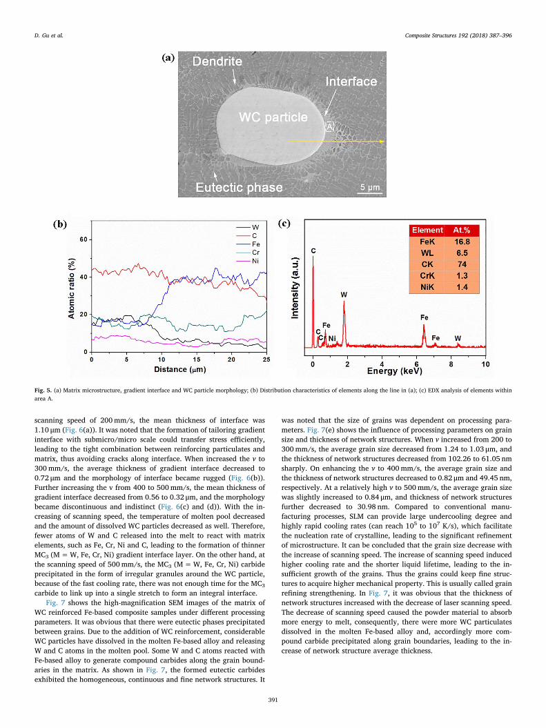
From the etched cross-sections of the WC reinforced Fe-basedcomposite samples, reinforcing particles, mounted in the matrix, can beclearly observed (Fig. 5(a)). The EDX element line scanning, shown inFig. 5(b), revealed that the iron element content was on an upwardtrend while the tungsten element content decreased along the directionfrom WC particle to matrix, illustrating that the interface between re-inforcing particle and matrix was gradient. The formation of gradientinterfacial layer demonstrated that the in situ reaction between re-inforcing particle and matrix had occurred [32–34]. Meanwhile, it isnoted that the residual WC particles exhibited spherical or sub-sphaeroidal, which is different from the polygon morphology after ballmilling (Fig. 1 (c)). It can be attributed to the priority dissolution of thepolygonal parts of WC particles during laser melting [24,35].
Fig. 5(c) indicates the EDX analysis in area A in Fig. 5(a). The EDXresult revealed that C, W and Fe elements were detected in the gradientinterface, in which the atomic percentage of C was 74 at.%. The atomicratio of carbon element and metallic elements (74 at.% versus 26 at.%)was close to 3:1, therefore the interface could be identified as MC3
(M=W, Fe, Cr, Ni) carbide. As depicted in Fig. 6, it can be obviouslyobserved that the thickness and morphology of gradient interface wereaffected significantly by laser processing parameters. At a relatively low
Fig. 4. Morphology of the molten pool of SLM-processed WC reinforced Fe-based composite samples at different parameters: (a) v=200mm/s, P=78W; (b) v=300mm/s, P=78W;(c) v=400mm/s, P=78W; (d) v=500mm/s, P=78W.
D. Gu et al. Composite Structures 192 (2018) 387–396
390
scanning speed of 200mm/s, the mean thickness of interface was1.10 μm (Fig. 6(a)). It was noted that the formation of tailoring gradientinterface with submicro/micro scale could transfer stress efficiently,leading to the tight combination between reinforcing particulates andmatrix, thus avoiding cracks along interface. When increased the v to300mm/s, the average thickness of gradient interface decreased to0.72 μm and the morphology of interface became rugged (Fig. 6(b)).Further increasing the v from 400 to 500mm/s, the mean thickness ofgradient interface decreased from 0.56 to 0.32 μm, and the morphologybecame discontinuous and indistinct (Fig. 6(c) and (d)). With the in-creasing of scanning speed, the temperature of molten pool decreasedand the amount of dissolved WC particles decreased as well. Therefore,fewer atoms of W and C released into the melt to react with matrixelements, such as Fe, Cr, Ni and C, leading to the formation of thinnerMC3 (M=W, Fe, Cr, Ni) gradient interface layer. On the other hand, atthe scanning speed of 500mm/s, the MC3 (M=W, Fe, Cr, Ni) carbideprecipitated in the form of irregular granules around the WC particle,because of the fast cooling rate, there was not enough time for the MC3
carbide to link up into a single stretch to form an integral interface.Fig. 7 shows the high-magnification SEM images of the matrix of
WC reinforced Fe-based composite samples under different processingparameters. It was obvious that there were eutectic phases precipitatedbetween grains. Due to the addition of WC reinforcement, considerableWC particles have dissolved in the molten Fe-based alloy and releasingW and C atoms in the molten pool. Some W and C atoms reacted withFe-based alloy to generate compound carbides along the grain bound-aries in the matrix. As shown in Fig. 7, the formed eutectic carbidesexhibited the homogeneous, continuous and fine network structures. It
was noted that the size of grains was dependent on processing para-meters. Fig. 7(e) shows the influence of processing parameters on grainsize and thickness of network structures. When v increased from 200 to300mm/s, the average grain size decreased from 1.24 to 1.03 μm, andthe thickness of network structures decreased from 102.26 to 61.05 nmsharply. On enhancing the v to 400mm/s, the average grain size andthe thickness of network structures decreased to 0.82 μm and 49.45 nm,respectively. At a relatively high v to 500mm/s, the average grain sizewas slightly increased to 0.84 μm, and thickness of network structuresfurther decreased to 30.98 nm. Compared to conventional manu-facturing processes, SLM can provide large undercooling degree andhighly rapid cooling rates (can reach 105 to 107 K/s), which facilitatethe nucleation rate of crystalline, leading to the significant refinementof microstructure. It can be concluded that the grain size decrease withthe increase of scanning speed. The increase of scanning speed inducedhigher cooling rate and the shorter liquid lifetime, leading to the in-sufficient growth of the grains. Thus the grains could keep fine struc-tures to acquire higher mechanical property. This is usually called grainrefining strengthening. In Fig. 7, it was obvious that the thickness ofnetwork structures increased with the decrease of laser scanning speed.The decrease of scanning speed caused the powder material to absorbmore energy to melt, consequently, there were more WC particulatesdissolved in the molten Fe-based alloy and, accordingly more com-pound carbide precipitated along grain boundaries, leading to the in-crease of network structure average thickness.
Fig. 5. (a) Matrix microstructure, gradient interface and WC particle morphology; (b) Distribution characteristics of elements along the line in (a); (c) EDX analysis of elements withinarea A.
D. Gu et al. Composite Structures 192 (2018) 387–396
391

3.3. Microhardness and wear property
Fig. 8(a) shows the Vickers microhardness on the cross-section ofSLMed WC reinforced Fe-based composites. When the v increased from200mm/s to 300mm/s, the mean microhardness increased from 494.4HV0.2 to 511.6 HV0.2. As the v was settled as 400 and 500mm/s, themean microhardness decreased to 484.0 HV0.2 and 478.5 HV0.2, re-spectively. According to Figs. 3 and 8(a), it could be concluded that thevariation of microhardness was linked with densification of WC re-inforced Fe-based composites. In general, higher densification led tohigher microhardness. On the other hand, fine grains would increasethe microhardness of composites. Due to the combination of densifi-cation and fine grains, the highest microhardness of 511.6 HV0.2 wasobtained at scanning speed of 300mm/s. In addition, the gradient layerand homogeneous intergranular eutectic carbides also played an im-portant role in the enhancement of microhardness of composite partsowing to higher carbon content.
Fig. 8(b) and (c) depict the coefficients of friction (COF) and wearrates of SLMed WC reinforced Fe-based composite samples with dif-ferent laser processing parameters. Figs. 9 and 10 shows the morphol-ogies of worn surface under different magnification of SLMed WC re-inforced Fe-based composite parts. It could be found that laser scanningspeed (v) played a key role in determining the wear performance. At thelowest v of 200mm/s, the COF was 0.43, with a resultant wear rate of3.7× 10−5 mm3/(Nm). On the worn surface, there were massive largehierarchical flakes, leading to the formation of localized tribolayersresulting from considerable degree of plastic deformation during thewear test (Figs. 9(a) and 10(a)). On increasing the v to 300mm/s, thelowest COF of 0.30 with attendant lowest wear rate of3.1× 10−5 mm3/(Nm) was obtained. And the fluctuation of COF curvewas very mild, indicating that the worn surface is smooth which havebeen demonstrated by Figs. 9(b) and 10(b). The worn surface exhibitedvery smooth and was almost covered by protective tribolayer, but alittle of wear debris and shallow grooves were observed (Fig. 9(b)). Aclean, dense and smooth worn surface without any wear debris was
obtained in high-magnification image (Fig. 10(b)). When the applied vincreased to 400 and 500mm/s, the COF of sample reached as high as0.54 and 0.69, respectively, leading to relatively large wear rate of5.5× 10−5 and 7.8× 10⁻⁵ mm3/(Nm). In addition, the fluctuation ofCOF curve were severe, because of the low relative densities of thesamples. At the v of 400mm/s, a minor degree of plastic deformationcould be observed, and the worn surface exhibited smoother (Fig. 9(c)).Some wear debris were observed in higher magnification image, andthe adherent tribolayer emerged on the worn surface (Fig. 10(c)). At aneven higher v of 500mm/s, the worn surface appeared rough and itcould be judged that severe plastic deformation occurred. Meanwhile,smooth particle border became rugged, revealing these particles havebeen worn away partially (Fig. 9(d)). Higher magnification SEM imageillustrates that the wear scars were observed to adhere to the wornsurface, which were considered to be representative characteristics ofadhesive wear mechanism. In addition, microcracks were found on theworn surface. Severe plastic deformation of surface materials duringsliding test led to case-hardening, producing stress concentration andgenerating cracks on the worn surface finally (Fig. 10(d)).
In order to further understand the enhancement mechanism on wearperformance of WC reinforced Fe-based composites, a comprehensiverelationship between densification, tailoring gradient interface, micro-structure and microhardness is discussed as follows. At first, on theoccasion of low densification at relatively high v, material is apt to beremoval from matrix owing to mass pores. With the decrease of appliedv, the resultant improved densification ensures the better wear perfor-mance. Secondly, the in-situ gradient interface is believed to play animportant role in improving the wear performance. It is reported thatthe deterioration of wear property of composites has been attributed tothe poor interfacial bond between the reinforcement particles and thematrix [36]. The interface free of pores or cracks assures the coherentbonding between reinforcement particulate and matrix, and it shouldbe noted that the effect of thickness of tailoring gradient interface couldnot be ignored. The thicker the gradient interface, the stronger thebinding force, accordingly WC particle is difficult to be worn away
Fig. 6. Morphologies of the WC particles and gradient interface of the WC reinforced Fe-based composite samples at different parameters: (a) P=78W, v=200mm/s; (b) P=78W,v=300mm/s; (c) P=78W, v=400mm/s; (d) P=78W, v=500mm/s.
D. Gu et al. Composite Structures 192 (2018) 387–396
392

during dry sliding test, so the wear performance is promoted. On theother hand, a complete interface is conducive to preventing crackpropagation. Moreover, microhardness of sample can be improved dueto fine grains, residual unmelted WC particles and intergranular car-bides. According to the modified empirical equation [37]:
=W k P H( / ) (4)
where W is wear rate, P is an applied load, H is the hardness of mate-rials, and k is a pre-factor relative to the ductility of material. Under theconstant k and P, an increase in microhardness can restrict the onset ofadhesive process such as scuffing and seizure of material, resulting inthe lower wear rate, thus the improved wear resistance of samples. Inconclusion, the synergy of the improved densification, the generation oftailoring gradient interface, fine microstructure and enhanced
Fig. 7. Characteristics of the etched microstructures of SLM-processed WC reinforced Fe-based composite samples at different parameters: (a) P=78W, v=200mm/s; (b) P=78W,v=300mm/s; (c) P=78W, v=400mm/s; (d) P=78W, v=500mm/s. (e) Average grain size and the thickness of network structures in the matrix of samples at different parameters.
D. Gu et al. Composite Structures 192 (2018) 387–396
393

Fig. 8. Microhardness (a), Coefficient of friction (b), and wear rate (c) of SLM-processed WC reinforced Fe-based composite samples under various processing parameters.
Fig. 9. Morphologies of worn surface of SLM-processed WC reinforced Fe-based composite samples under various processing parameters: (a) P=78W, v=200mm/s; (b) P=78W,v=300mm/s; (c) P=78W, v=400mm/s; (d) P=78W, v=500mm/s.
D. Gu et al. Composite Structures 192 (2018) 387–396
394

microhardness results in the improved wear performance.
4. Conclusions
(1) The gradient interface identified as MC3 (M=W, Fe, Cr, Ni) formedbetween WC particle and matrix due to the in-situ reaction underlaser processing. It was reasonable to consider that the generationof gradient interface was beneficial to improving the bondingstrength between WC reinforcing particle and matrix. The thicknessand morphology of tailoring gradient interface were influencedsignificantly by the laser processing parameters.
(2) Network structures of eutectic phase uniformly distributed in thematrix of SLMed WC reinforced Fe-based composites. The grains ofmatrix became fine with the increase of the scanning speed. At thescanning speed of 400mm/s (laser power=78W), the mean grainsize achieved the smallest value of 0.82 μm. The thickness of net-work structures decreased with the increase of the scanning speedowing to the reduced dissolution of WC particles.
(3) The densification of SLMed WC reinforced Fe-based composites wasinfluenced by processing parameters. Insufficient laser energy inputresulting from low laser power and high scanning speed led to theformation of large inter-layer pores with irregular shapes due to thepoor wettability of melt, and the limited densification. At the op-timal processing parameter (v=200mm/s, P=100W), the SLMedWC reinforced Fe-based composites showed the highest relativedensity of 98.5%.
(4) The mechanical properties of WC reinforced Fe-based compositeswere affected significantly by processing parameters. At the optimalv of 300mm/s (laser power=78W), the microhardness came up to511.6 HV0.2. Meanwhile, a low COF of 0.30 with a mild fluctuationwas obtained, resulting in a considerably low wear rate of3.1× 10−5 mm3/(Nm). The enhancement of wear performancewas the synergy of tailoring gradient interface, enhanced densifi-cation, fine microstructures and higher microhardness.
Acknowledgements
The authors gratefully acknowledge the financial support from theNational Natural Science Foundation of China (No. 51575267), theNational Key Research and Development Program “AdditiveManufacturing and Laser Manufacturing” (No. 2016YFB1100101), theKey Research and Development Program of Jiangsu ProvincialDepartment of Science and Technology of China (No. BE2016181), thePriority Academic Program Development of Jiangsu Higher EducationInstitutions, and the Funding of Jiangsu Innovation Program forGraduate Education (KYLX16_0344).
References
[1] Olakanmi EO, Cochrane RF, Dalgarno KW. A review on selective laser sintering/melting (SLS/SLM) of aluminium alloy powders: Processing, microstructure, andproperties. Prog Mater Sci 2015;74:401–77.
[2] Kang N, Coddet P, Wang J, Yuan H, Ren ZM, Liao HL, et al. A novel approach to in -situ produce functionally graded silicon matrix composite materials by selectivelaser melting. Compos Struct 2017;172:251–8.
[3] Gu DD, Meiners W, Wissenbach K, Poprawe R. Laser additive manufacturing ofmetallic components: materials, processes and mechanisms. Int Mater Rev2013;57:133–64.
[4] Gu DD. Laser additive manufacturing of high-performance materials. first ed. BerlinHeidelberg, Germany: Springer-Verlag; 2015.
[5] Liu FH, Shen YK, Liao YS. Selective laser gelation of ceramic–matrix composites.Compos B Eng 2011;42:57–61.
[6] Shishkovsky I, Kakovkina N, Sherbakov V. Graded layered titanium compositestructures with TiB 2 inclusions fabricated by selective laser melting. Compos Struct2017;169:90–6.
[7] Gu DD, Hagedorn YC, Meiners W, Meng GB, Batista RJS, Wissenbach K, et al.Densification behavior, microstructure evolution, and wear performance of selec-tive laser melting processed commercially pure titanium. Acta Mater2012;60:3849–60.
[8] Thijs L, Verhaeghe F, Craeghs T, Humbeeck JV, Kruth JP. A study of the micro-structural evolution during selective laser melting of Ti–6Al–4V. Acta Mater2010;58:3303–12.
[9] Zhang BC, Liao HL, Coddet C. Microstructure evolution and density behavior of CPTi parts elaborated by Self-developed vacuum selective laser melting system. ApplSurf Sci 2013;279:310–6.
[10] Xia MJ, Gu DD, Yu GQ, Dai DH, Chen HY, Shi QM. Selective laser melting 3Dprinting of Ni-based superalloy: understanding thermodynamic mechanisms. Sci
Fig. 10. High-magnification of worn surface morphologies of SLM-processed WC reinforced Fe-based composite samples under various processing parameters: (a) P=78W,v=200mm/s; (b) P=78W, v=300mm/s; (c) P=78W, v=400mm/s; (d) P=78W, v=500mm/s.
D. Gu et al. Composite Structures 192 (2018) 387–396
395

Bull 2016;61:1013–22.[11] Olakanmi EO. Selective laser sintering/melting (SLS/SLM) of pure Al, Al–Mg, and
Al–Si powders: effect of processing conditions and powder properties. J MaterProcess Technol 2013;213:1387–405.
[12] Thijs L, Kempen K, Kruth JP, Van Humbeeck J. Fine-structured aluminium productswith controllable texture by selective laser melting of pre-alloyed AlSi10Mgpowder. Acta Mater 2013;61:1809–19.
[13] Li RD, Wang MB, Yuan TC, Song B, Chen C, Zhou KC, et al. Selective laser melting ofa novel Sc and Zr modified Al-6.2 Mg alloy: Processing, microstructure, and prop-erties. Powder Technol 2017;319:117–28.
[14] Li RD, Shi YS, Wang ZG, Wang L, Liu JH, Jiang W. Densification behavior of gas andwater atomized 316L stainless steel powder during selective laser melting. Appl SurfSci 2010;256:4350–6.
[15] Wang D, Song CH, Yang YQ, Bai YC. Investigation of crystal growth mechanismduring selective laser melting and mechanical property characterization of 316Lstainless steel parts. Mater Des 2016;100:291–9.
[16] Kruth JP, Froyen L, Van Vaerenbergh J, Mercelis P, Rombouts M, Lauwers B.Selective laser melting of iron-based powder. J Mater Process Technol2004;149:616–22.
[17] Attar H, Löber L, Funk A, Calin M, Zhang LC, Prashanth KG, et al. Mechanicalbehavior of porous commercially pure Ti and Ti–TiB composite materials manu-factured by selective laser melting. Mater Sci Eng, A 2015;625:350–6.
[18] Zhang XX, Xiao BL, Andrä H, Ma ZY. Homogenization of the average thermo-elastoplastic properties of particle reinforced metal matrix composites: theminimum representative volume element size. Compos Struct 2014;113:459–68.
[19] Nafar Dastgerdi J, Marquis G, Sankaranarayanan S, Gupta M. Fatigue crack growthbehavior of amorphous particulate reinforced composites. Compos Struct2016;153:782–90.
[20] An YK, Yang SY, Zhao ET, Wang ZS. Characterization of metal grid-structure re-inforced aluminum foam under quasi-static bending loads. Compos Struct 2017.
[21] Zhang BC, Bi GJ, Nai S, Sun CN, Wei J. Microhardness and microstructure evolutionof TiB2 reinforced Inconel 625/TiB2 composite produced by selective laser melting.Opt Laser Technol 2016;80:186–95.
[22] AlMangour B, Grzesiak D, Yang JM. Nanocrystalline TiC-reinforced H13 steel ma-trix nanocomposites fabricated by selective laser melting. Mater Des2016;96:150–61.
[23] Song B, Dong SJ, Coddet P, Zhou GS, Ouyang S, Liao HL, et al. Microstructure andtensile behavior of hybrid nano-micro SiC reinforced iron matrix composites pro-duced by selective laser melting. J Alloy Compd 2013;579:415–21.
[24] Zhou SF, Dai XQ. Microstructure evolution of Fe-based WC composite coating
prepared by laser induction hybrid rapid cladding. Appl Surf Sci 2010;256:7395–9.[25] Li LQ, Liu DJ, Chen YB, Wang CM, Li FQ. Electron microscopy study of reaction
layers between single-crystal WC particle and Ti–6Al–4V after laser melt injection.Acta Mater 2009;57:3606–14.
[26] Wang JD, Li LQ, Tao W. Crack initiation and propagation behavior of WC particlesreinforced Fe-based metal matrix composite produced by laser melting deposition.Opt Laser Technol 2016;82:170–82.
[29] Ramesh CS, Srinivas CK. Friction and wear behavior of laser-sintered iron–siliconcarbide composites. J Mater Process Technol 2009;209:5429–36.
[30] Takamichi I, Roderick ILG. The physical properties of liquid metals. Oxford, UK:Clarendon Press; 1993.
[31] Prashanth KG, Scudino S, Maity T, Das J, Eckert J. Is the energy density a reliableparameter for materials synthesis by selective laser melting? Mater Res Lett2017;5:386–90.
[32] Prashanth KG, Scudino S, Chaubey AK, Löber L, Wang P, Attar H, et al. Processing ofAl–12Si–TNM composites by selective laser melting and evaluation of compressiveand wear properties. J Mater Res 2015;31:55–65.
[33] Attar H, Boenisch M, Calin M, Zhang LC, Scudino S, Eckert J. Selective laser meltingof in situ titanium-titanium boride composites: processing, microstructure andmechanical properties. Acta Mater 2014;76:13–22.
[34] Scudino S, Liu G, Prashanth KG, Bartusch B, Surreddi KB, Murty BS, et al.Mechanical properties of Al-based metal matrix composites reinforced with Zr-based glassy particles produced by powder metallurgy. Acta Mater2009;57:2029–39.
[35] Zhou SF, Zeng XY. Growth characteristics and mechanism of carbides precipitatedin WC–Fe composite coatings by laser induction hybrid rapid cladding. J AlloyCompd 2010;505:685–91.
[36] Saka N, Karalekas DP. Friction and wear of particle-reinforced metal-ceramiccomposites. Wear Mater 1985;784.
[37] Zhang XH, Ma JQ, Yang J, Bi QL, Liu WM. Dry-sliding tribological behavior of Fe-28Al-5Cr/TiC composites. Wear 2011;271:881–8.
Further reading
[27] Ramesh CS, Srinivas CK, Channabasappa BH. Abrasive wear behaviour of lasersintered iron–SiC composites. Wear 2009;267:1777–83.
[28] Exner HE. Physical and chemical nature of cemented carbides. Int Met Rev1979;24:149–73.
D. Gu et al. Composite Structures 192 (2018) 387–396
396