lartpc-docdb.fnal.govlartpc-docdb.fnal.gov/.../orcreviewcomments_responses.docx · web viewfrom leo...
TRANSCRIPT
From Leo Bellantoni
1) You have a list of findings from Steve Chappa2) Likewise Karen Kephart3) and from Jim Priest, a single additional finding.
I have the following notes:
After looking at FESHM 6020.4 I don't think it is required to open space between the RTD pipe and the High Voltage rack - still, if this can be done, it would be an improvement.The HV rack was not moved due to the other constraints.
Similarly, I do not find a specific height that is required for an altitude that the cables that need to be strung from the TPC electronics rack to the top of the vessel; but obviously, the higher that they can be strung the better.The TPC has been cabled. A 6’ tall person can easily walk under the cables.
From Steve Chappa:
1. The DC and AC power wiring inside of the CCU chassis, which is a custom-built chassis, is not clear from the schematic and description. Therefore, I will need to physically look inside the chassis to examine the safety grounding and power wiring details. Also, the schematic needs to be updated/completed so as to include this information. One spare CCU chassis is at the Proton Pole Building (PPB) ready for inspection. We also updated the documentation for the CCU chassis:http://lartpc-docdb.fnal.gov/0008/000860/006/CCU_information_v2.pdfwhich provides dialog to accompany CCU schematics:http://lartpc-docdb.fnal.gov/0008/000860/006/CCU_PAD_schematics_bromberg.pdf
2. The power cords for the two scaler chassis, located within the Long Bo Counter rack, need to be strain relieved so that the weight of the cord does not pull on and stress the connector contacts.The power cords are strain-relieved.
1

3. HV danger signs need to be located on the HV rack up on the upper platform. In addition, HV Danger labels need to be attached to the black HV cable.HV signage has been posted.
4. The HV and signal RG58 cables connected to the large PMTs need to be checked for proper strain relief to prevent damage to the cables’ shield crimp connection.All the cables are strain-relieved.
5. One cold DAQ card installed has been revised since the review of these electronics back in 2011 (at PAB). Therefore, the revised module’s documentation needs to be examined to verify proper DC power implementation within the module.As used in LAPD Run II, 1 of the 9 preamp cards inside the cryostat, the CMB-16 cards, has been modified to include an ASIC preamp chip from BNL. The documentation for the modified TPC cold electronics inside the LAPD vessel ishttp://lartpc-docdb.fnal.gov/0008/000860/006/Note-ASIC-Card.pdf
2

The documentation for the modifications to the special WRP-16 card in the warm receiver crate ishttp://lartpc-docdb.fnal.gov/0008/000860/006/WRP-16-modification-note.pdfThe schematic for the ASIC control box ishttp://lartpc-docdb.fnal.gov/0008/000860/006/ASIC-control-box.pdf
6. Documentation for the electronics installed within the vessel needs to be examined. I did not see where this documentation is located. This documentation is located athttp://www.pa.msu.edu/~edmunds/LArTPC/Bo_Cold_DAQ/Safety_Review/cold_bo_daq_safety_review.txt
7. The PC-4 ODH Alarms Control Enclosure has been modified with the addition of two additional monitors. The updated drawing will be added to the documentation.Updated drawings for item 7 were provided on 11.15.12 and are posted here:http://lartpc-docdb.fnal.gov:8080/cgi-bin/RetrieveFile?docid=553;filename=EN_LAPD_CONTROLS%20-%20Rev_A.pdf;version=123 A follow-up review should be conducted that will include the final installation of the DAQ cables, power supply connections, rack protection installation, etc.
From Karen Kephart:
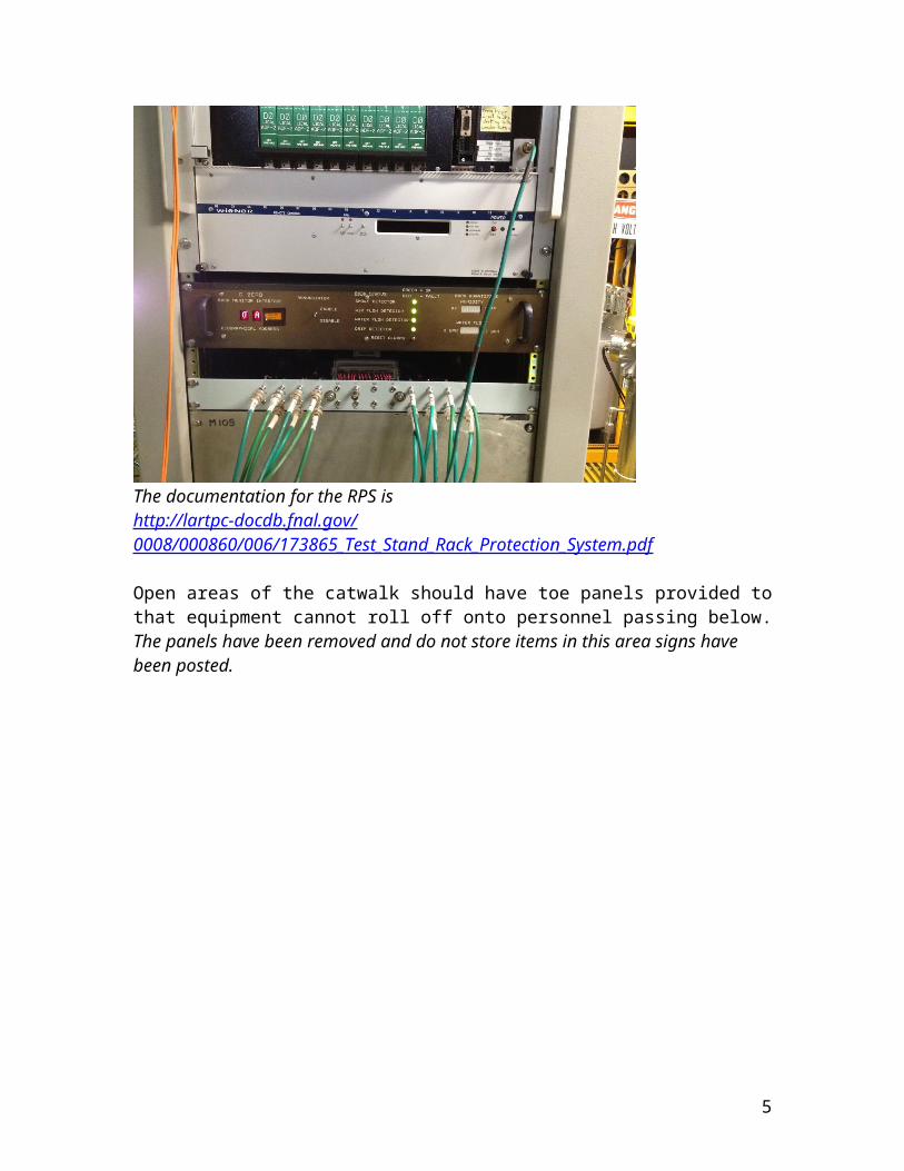
Scintillation counters need to have all the signal and HV cables going to PMT bases checked and appropriately strain-relieved.All the cables are strain-relieved, please see picture on page 2. Bubble wrap draped over one of the counters must be removed. If long term protection is needed, a non-flammable material must be chosen.Bubble wrap will be removed when the mastic work is done and prior to system startup. Any other plastic sheeting that has been draped to prevent splatters while insulating should be removed before start-up (I noticed a piece that was obstructing a visual on a shut-off valve, for example).All other sheeting will be removed when the mastic work is done and prior to system startup. The TPC electronics rack located on the catwalk at the top of the vessel needs to have rack protection provided of the type that includes (at a minimum) a smoke detector wired to turn off power to the rack in case of an alarm.Rack protection is installed and tested to be functional.
3
The documentation for the RPS ishttp://lartpc-docdb.fnal.gov/0008/000860/006/173865_Test_Stand_Rack_Protection_System.pdf
Open areas of the catwalk should have toe panels provided to that equipment cannot roll off onto personnel passing below.The panels have been removed and do not store items in this area signs have been posted.
4
I would like to revisit when the TPC is cabled to the rack on the catwalk.The TPC has been cabled. A 6’ tall person can easily walk under the cables.
From Jim Priest:
Terry was going to provide the FD with a diagram of the shut-off valves. The FD has already walked through the H2 part of LAPD. I would suggest the same walkthrough and when the shut of diagrams are ready before operation.The FD has been sent the documentation and invited for tours. The documentation is here:http://lartpc-docdb.fnal.gov:8080/cgi-bin/RetrieveFile?docid=868;filename=run_2_emergency_shutoff_valves_for_Fire_Department1.pdf;version=2
From Russ Rucinski and Tug Arkan
5

The plywood under the ladder should be repositioned.The plywood has been repositioned.
6