large generators and high power drives...manufacturing of large electrical machines 2. heating and...
TRANSCRIPT
Institut für Elektrische
Energiewandlung • FB 18
TECHNISCHE
UNIVERSITÄT
DARMSTADT
Prof. A. Binder : Large Generators & High Power Drives
2/1
Large Generators and High Power Drives
1. Manufacturing of Large Electrical Machines
2. Heating and cooling of electrical machines
3. Eddy current losses in winding systems
4. Excitation of synchronous machines
5. Design of large synchronous machines
6. Wind generators and high power drives
7. Forces in big synchronous machines
Contents of lectures
Source:
Siemens AG, Germany

Institut für Elektrische
Energiewandlung • FB 18
TECHNISCHE
UNIVERSITÄT
DARMSTADT
Prof. A. Binder : Large Generators & High Power Drives
2/2
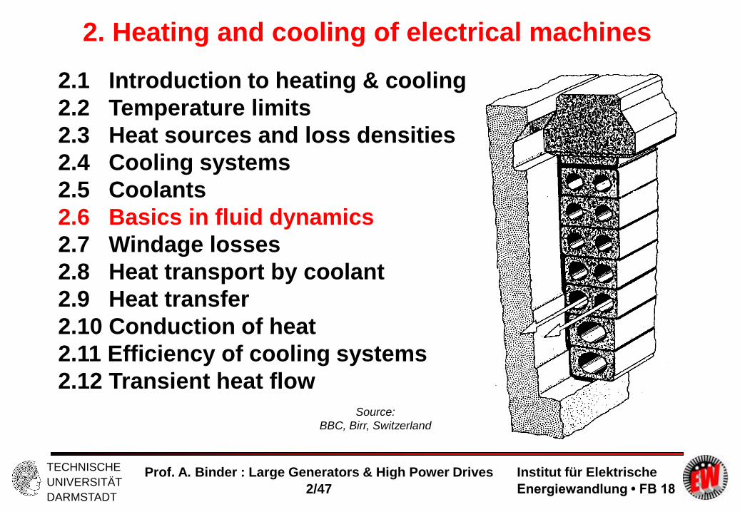
2. Heating and cooling of electrical machines
2.1 Introduction to heating & cooling
2.2 Temperature limits
2.3 Heat sources and loss densities
2.4 Cooling systems
2.5 Coolants
2.6 Basics in fluid dynamics
2.7 Windage losses
2.8 Heat transport by coolant
2.9 Heat transfer
2.10 Conduction of heat
2.11 Efficiency of cooling systems
2.12 Transient heat flow
Source:
BBC, Birr, Switzerland

Institut für Elektrische
Energiewandlung • FB 18
TECHNISCHE
UNIVERSITÄT
DARMSTADT
Prof. A. Binder : Large Generators & High Power Drives
2/3
2. Heating and cooling of electrical machines
2.1 Introduction to heating & cooling
Why must the winding temperature be limited?
- Electrical insulation of the windings (at AC operating voltage, e.g. 50 Hz) against
the iron core (grounded at zero potential for safety reasons) must withstand for ca.
40 years
- Enameled copper conductors + coil insulation system for certain temperature limits
(“Thermal Classes” e.g. B, F, H according to IEC 60034-1)
- Test voltage UTest = rated machine voltage UN (line-to-line, r.m.s.) + 1000 V
e.g. UN = 3 kV, UTest = 2.3 + 1 = 7 kV, 50 Hz, for 5 s (IEC 60034-1)
- Low voltage windings = UN up to 1 kV
- High voltage windings = UN > 1 kV (typically up to 30 kV)
- Low voltage insulation systems based on insulation paper (special plastic foils) and
epoxy resin impregnation
- High voltage insulation systems based on mica, glass fibre and resin impregnation
Institut für Elektrische
Energiewandlung • FB 18
TECHNISCHE
UNIVERSITÄT
DARMSTADT
Prof. A. Binder : Large Generators & High Power Drives
2/4
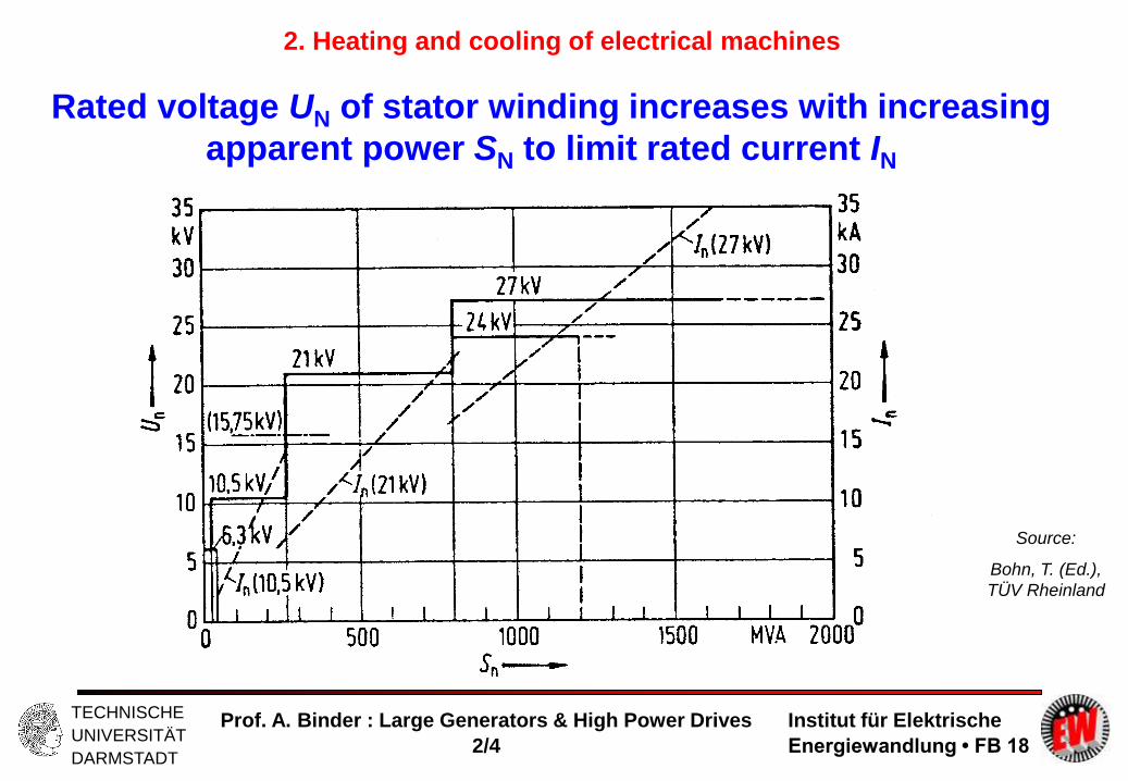
Rated voltage UN of stator winding increases with increasing
apparent power SN to limit rated current IN
Source:
Bohn, T. (Ed.),
TÜV Rheinland
2. Heating and cooling of electrical machines

Institut für Elektrische
Energiewandlung • FB 18
TECHNISCHE
UNIVERSITÄT
DARMSTADT
Prof. A. Binder : Large Generators & High Power Drives
2/5
Thermal classes of insulation systems Example: (IEC60034-1)
Thermal Class B: 40°C + 80 K + 10 K = 130°C
Thermal Class F: 40°C + 105 K + 10 K = 155°C (rated power 5 MW)
Thermal Class F: 40°C + 100 K + 10 K = 150°C (rated power > 5 MW)
Thermal Class H: 40°C + 125 K + 15 K = 180°C
Ambient temperature average temperature rise add. hot spot temperature rise temperature limit
Source: ABB, Switzerland
Example:
Totally enclosed fan cooled
cage induction motor (TEFC)
Cool inlet side Hot outlet side
2. Heating and cooling of electrical machines

Institut für Elektrische
Energiewandlung • FB 18
TECHNISCHE
UNIVERSITÄT
DARMSTADT
Prof. A. Binder : Large Generators & High Power Drives
2/6
2. Heating and cooling of electrical machines
Montsinger´s rule
Montsinger´s rule for transformer oil, resin or solid foil insulation materials:
Insulation life span L decreases by 50% (taken as average of a large number of
tested specimen) with increase of insulation temperature by 10 K.
)(5.0)10( LKL Example:
Insulation material for Thermal Class F: hours
hours 100000)155( CL
50000)165( CL
"KELVIN-temperature" T; unit K (basic SI-unit)
CELSIUS-Temperature ; unit °C
T = + 273.15
Temperature rise: = 2 - 1; unit K

Institut für Elektrische
Energiewandlung • FB 18
TECHNISCHE
UNIVERSITÄT
DARMSTADT
Prof. A. Binder : Large Generators & High Power Drives
2/7
2. Heating and cooling of electrical machines
High voltage winding insulation (> 1kV) based on Mica
- Mica has a rather temperature-independent break-down field strength ED,M and
permittivity M
- Mica splitting (A > 1 cm2) versus Mica flakes ((A < 1cm2)
- Older system: Mica flakes embedded in epoxy resin
- Modern system: Mica splitting as layers, glued on glass fibre tapes, with resin
impregnation in between the layers
- Permittivity R of resin increases with temperature Mica splitting: ER in resin
decreases
Partial discharge inception voltage INcreases with increasing temperature =
= EXCEPTION from MONTSINGER´s rule !

Institut für Elektrische
Energiewandlung • FB 18
TECHNISCHE
UNIVERSITÄT
DARMSTADT
Prof. A. Binder : Large Generators & High Power Drives
2/8
2. Heating and cooling of electrical machines
Exception from MONTSINGER´s rule:
Mica splitting and resin compound
Partial discharge inception voltage in the resin (with air voids) occurs, when ER reaches
break-down limit ED,R
Result: Partial discharge inception voltage INcreases with increasing temperature
)1()( UzdEE RM
z layers of mica splitting and resin impregnation
RRRMMM EDDE )2()())(/( RMRM EE
permittivity R of resin increases with temperature
permittivity M of mica is independent of
)()(:)2(),1(
RM
MR
dz
UE
mica resin d
EM ER
U

Institut für Elektrische
Energiewandlung • FB 18
TECHNISCHE
UNIVERSITÄT
DARMSTADT
Prof. A. Binder : Large Generators & High Power Drives
2/9
2. Heating and cooling of electrical machines
- Air voids in the insulation have ca. 4-times higher field strength Small arcing occurs
(“partial discharge” = “corona”)
- Partial discharge inception U = UPD, when Eair = ED (break down field strength)
- UPD decreases with increasing temperature
U
U = 0
air void
conductor
insulation
Ei Eair
i 0
insulation thickness di , void width dv
U
)/( 0 iivair
dd
UE
iairiiv
d
UEdd 4:4, 0
Partial discharges in high voltage windings

Institut für Elektrische
Energiewandlung • FB 18
TECHNISCHE
UNIVERSITÄT
DARMSTADT
Prof. A. Binder : Large Generators & High Power Drives
2/10
2. Heating and cooling of electrical machines
Partial discharge (PD) between coil & slot insulation: It may be bridged by semi-conducting
“anti-corona” screen (graphite layer) between coil & slot insulation to avoid PD
Anti-corona screen in high voltage windings
U
U = 0
air void
conductor
insulation
“anti-corona” screen
Contact points between “anti-
corona” and slot insulation bridge
the gap
Contact points between “anti-corona” and slot insulation bridge the gap: A very small
current flows via the screen to the ground. The voltage drop at the screen is much
smaller than the PD inception voltage = the PD is extinguished!

Institut für Elektrische
Energiewandlung • FB 18
TECHNISCHE
UNIVERSITÄT
DARMSTADT
Prof. A. Binder : Large Generators & High Power Drives
2/11
High voltage form wound stator coil with several turns Nc
for two-layer winding
Winding overhang,
painted with humid-
resistant red varnish
coil side, inserted in slot,
with back graphite “anti-
corona” screen
coil terminals
Source:
Andritz Hydro, Austria
2. Heating and cooling of electrical machines

Institut für Elektrische
Energiewandlung • FB 18
TECHNISCHE
UNIVERSITÄT
DARMSTADT
Prof. A. Binder : Large Generators & High Power Drives
2/12
Large Generators and High Power Drives
Summary:
Introduction to heating & cooling
- MONTSINGER´s rule, based on ARRHENIUS´ law of chemical processes,
describes insulation material deterioration due to high temperatures
- High-voltage insulation systems above 1 kV
- High-voltage systems use mica and vacuum impregnated resin
- High voltage insulation always subjected to partial discharge

Institut für Elektrische
Energiewandlung • FB 18
TECHNISCHE
UNIVERSITÄT
DARMSTADT
Prof. A. Binder : Large Generators & High Power Drives
2/13
2. Heating and cooling of electrical machines
2.1 Introduction to heating & cooling
2.2 Temperature limits
2.3 Heat sources and loss densities
2.4 Cooling systems
2.5 Coolants
2.6 Basics in fluid dynamics
2.7 Windage losses
2.8 Heat transport by coolant
2.9 Heat transfer
2.10 Conduction of heat
2.11 Efficiency of cooling systems
2.12 Transient heat flow
Source:
BBC, Birr, Switzerland

Institut für Elektrische
Energiewandlung • FB 18
TECHNISCHE
UNIVERSITÄT
DARMSTADT
Prof. A. Binder : Large Generators & High Power Drives
2/14
2. Heating and cooling of electrical machines
2.2 Temperature limits
ThermalClass
INS.: Insulation material / IMP.: Impregnation Temperaturelimit
A INS.: cotton, paper, wood, ...IMP.: asphalt, shellac
105 oC
E INS.: wire resin based on polyvinylacetate or epoxy;Impregnated paper; IMP.: synthetic resin
120 oC
B INS.: glass fibre, asbestos, mica ...IMP.: asphalt, shellac, resin varnish
130 oC
F INS.: as B, IMP.: Epoxy-resin 155 oC
H INS.: as B, IMP.: Silicon-resin; silicon-rubber 180 oC
200 INS.: mica, ceramics, glass, quartz ... 240 oC

Institut für Elektrische
Energiewandlung • FB 18
TECHNISCHE
UNIVERSITÄT
DARMSTADT
Prof. A. Binder : Large Generators & High Power Drives
2/15
2. Heating and cooling of electrical machines
Thermal Class E B F H
AC winding (e.g. three-phase)Excitation winding (DC) Single layer, non-insulated surface Coils for cylindrical rotor
75 K75 K80K-
80 K80 K90 K90 K
100 K*)100 K110 K110 K
125 K125 K135 K-
*) For rated apparent power less than SN = 5 MVA: 105 K
Indirect air cooling (IEC 60034-1): Maximum admissible temperature rise (at
40°C ambient temperature = coolant´s temperature)
Maximum admissible temperature rise
Thermal class E B F H
Hot spot temperature rise overaverage temperature rise 5 K 10K 15K 15 K
Average temperature rise: Measured via DC resistance cold and hot:
Hot spot temperature rise: Measured with thermo-couples (e.g. Fe-Constantan)
)1(20 CRR
Institut für Elektrische
Energiewandlung • FB 18
TECHNISCHE
UNIVERSITÄT
DARMSTADT
Prof. A. Binder : Large Generators & High Power Drives
2/16
2. Heating and cooling of electrical machines
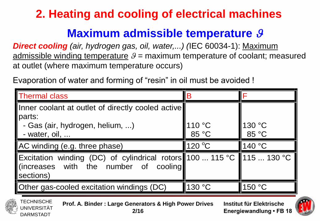
Maximum admissible temperature Direct cooling (air, hydrogen gas, oil, water,...) (IEC 60034-1): Maximum
admissible winding temperature = maximum temperature of coolant; measured
at outlet (where maximum temperature occurs)
Evaporation of water and forming of “resin” in oil must be avoided !
Thermal class B F
Inner coolant at outlet of directly cooled activeparts: - Gas (air, hydrogen, helium, ...) - water, oil, ...
110 °C 85 °C
130 °C 85 °C
AC winding (e.g. three phase) 120 oC 140 °C
Excitation winding (DC) of cylindrical rotors(increases with the number of coolingsections)
100 ... 115 °C 115 ... 130 °C
Other gas-cooled excitation windings (DC) 130 °C 150 °C

Institut für Elektrische
Energiewandlung • FB 18
TECHNISCHE
UNIVERSITÄT
DARMSTADT
Prof. A. Binder : Large Generators & High Power Drives
2/17
Large Generators and High Power Drives
Summary:
Temperature limits
- Temperature limit due to Thermal Class (Th. Cl.) of used insulation system
- Often Th. Cl. F used, but operation only up to Th. Cl. B to increase insulation
life-span
- Different temperature limits, depending on cooling system

Institut für Elektrische
Energiewandlung • FB 18
TECHNISCHE
UNIVERSITÄT
DARMSTADT
Prof. A. Binder : Large Generators & High Power Drives
2/18
2. Heating and cooling of electrical machines
2.1 Introduction to heating & cooling
2.2 Temperature limits
2.3 Heat sources and loss densities
2.4 Cooling systems
2.5 Coolants
2.6 Basics in fluid dynamics
2.7 Windage losses
2.8 Heat transport by coolant
2.9 Heat transfer
2.10 Conduction of heat
2.11 Efficiency of cooling systems
2.12 Transient heat flow
Source:
BBC, Birr, Switzerland

Institut für Elektrische
Energiewandlung • FB 18
TECHNISCHE
UNIVERSITÄT
DARMSTADT
Prof. A. Binder : Large Generators & High Power Drives
2/19
2. Heating and cooling of electrical machines
2.3 Heat sources and loss densities pd = Pd/V (W/m3)
VPJp Cud //2
1. Copper losses and winding eddy-current losses: 0.15...1...5 W/cm3
Example:
= 120°C, Cu, = 1/1.39. Cu,20°C = 41 Smm2/m, J = 7 A/mm2
VPJp CuCud // ,2 = 1.19 W/cm3
2. Iron losses (hysteresis and eddy current losses): at 50 Hz: 0.03...0.15 W/cm3
Example:Iron sheet: v10 = 1.7 W/kg (at 1 T, 50 Hz in EPSTEIN-frame).
In stator teeth: tooth flux density 1.8 T Zahninduktion (Fe = 7850
kg/m3): 4323778508.17.1 2 FeP W/m3, 043.0dp W/cm3. Increase
of losses due to manufacturing & field harmonics: kVd = 1.85:dp 0.08 W/cm3.
3. Additional eddy current losses in conducting parts; friction and windage losses
Institut für Elektrische
Energiewandlung • FB 18
TECHNISCHE
UNIVERSITÄT
DARMSTADT
Prof. A. Binder : Large Generators & High Power Drives
2/20
Large Generators and High Power Drives
Summary:
Heat sources and loss densities
- Highest loss densities in the copper conductors
- Direct conductor cooling improves reduction of winding temperature
- High-voltage insulation is „thermal resistance“, therefore again direct conductor
cooling preferred

Institut für Elektrische
Energiewandlung • FB 18
TECHNISCHE
UNIVERSITÄT
DARMSTADT
Prof. A. Binder : Large Generators & High Power Drives
2/21
2. Heating and cooling of electrical machines
2.1 Introduction to heating & cooling
2.2 Temperature limits
2.3 Heat sources and loss densities
2.4 Cooling systems
2.5 Coolants
2.6 Basics in fluid dynamics
2.7 Windage losses
2.8 Heat transport by coolant
2.9 Heat transfer
2.10 Conduction of heat
2.11 Efficiency of cooling systems
2.12 Transient heat flow
Source:
BBC, Birr, Switzerland

Institut für Elektrische
Energiewandlung • FB 18
TECHNISCHE
UNIVERSITÄT
DARMSTADT
Prof. A. Binder : Large Generators & High Power Drives
2/22
Open ventilation Totally enclosedmachines –
surface cooling
Totally enclosedmachines withheat exchanger
Hollow conductorcooling
Coolant air Coolant air or waterjacket
Coolant airHeat exchanger:air-air or air-water
Coolant hydrogengas, oil or de-ionized water
End shields ofmachine are open
for coolant flow
Increase of machinesurface by fins or
tubes for airWater jacket cooling
Coolant flow isdirected through
machine and heatexchanger in closed
loop
Pump pressescoolant through
hollow conductors
Usually up to 500kW, at higher
power acousticnoise is too big
Usually up to 2000kW
Up to 400 MW("top air" turbo
generators)
Up to biggestmachine power
(2000 MW)
Often shaftmounted fan
Often shaftmounted fan
Shaft mounted fans,external fans
External pump
2. Heating and cooling of electrical machines
2.4 Cooling systems

Institut für Elektrische
Energiewandlung • FB 18
TECHNISCHE
UNIVERSITÄT
DARMSTADT
Prof. A. Binder : Large Generators & High Power Drives
2/23
No fan Shaft mounted fan Externally driven fan
Cooling only due to naturalconvection and heat radiation
Speed dependent air flow forcooling
Air flow independent of motorspeed
Used for small machines(< 1 kW), e.g. permanent
magnet machines due to theirlower losses
Used for constant speeddrives
Big machine power possible
Used for variable speed drives
Big machine power possible
Air cooled machines - coolant is air flow
Shaft mounted fan,
fan hood for guiding air flow with air inlet
opening,
totally enclosed cage induction machine,
cooling fins on cooling surface
2. Heating and cooling of electrical machines
Totally enclosed machine – surface
cooling
Source: ABB, Switzerland
Institut für Elektrische
Energiewandlung • FB 18
TECHNISCHE
UNIVERSITÄT
DARMSTADT
Prof. A. Binder : Large Generators & High Power Drives
2/24
2. Heating and cooling of electrical machines
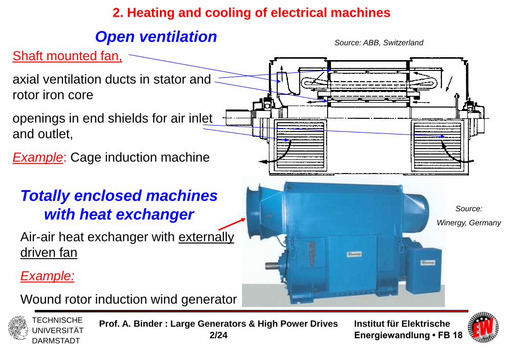
Open ventilation
Shaft mounted fan,
axial ventilation ducts in stator and
rotor iron core
openings in end shields for air inlet
and outlet,
Example: Cage induction machine
Totally enclosed machines
with heat exchanger
Air-air heat exchanger with externally
driven fan
Example:
Wound rotor induction wind generator
Source: ABB, Switzerland
Source:
Winergy, Germany

Institut für Elektrische
Energiewandlung • FB 18
TECHNISCHE
UNIVERSITÄT
DARMSTADT
Prof. A. Binder : Large Generators & High Power Drives
2/25
2. Heating and cooling of electrical machines
Hollow conductor = direct conductor cooling
a) Rotor: Direct hydrogen gas cooled hollow copper conductors
b) Stator: Direct water cooled hollow copper conductors
b)
a)
Example: Two-pole turbine generator
Source:
BBC, Birr, Switzerland

Institut für Elektrische
Energiewandlung • FB 18
TECHNISCHE
UNIVERSITÄT
DARMSTADT
Prof. A. Binder : Large Generators & High Power Drives
2/26
Turbine generator cut-view
Hollow copper conductors as
axial cooling channels
Up to 500 MVA the whole
generator stator is
impregnated (vacuum
pressurized)
Independent heat
exchangers
Source:
Siemens AG,
Mülheim/Ruhr,
Germany
2. Heating and cooling of electrical machines

Institut für Elektrische
Energiewandlung • FB 18
TECHNISCHE
UNIVERSITÄT
DARMSTADT
Prof. A. Binder : Large Generators & High Power Drives
2/27
2. Heating and cooling of electrical machines
Indirect gas cooling of turbine generator rotor field winding
Axial ventilation ducts
in rotor teeth
Radial outlet channels
Axial ventilation ducts
in rotor teeth
Radial outlet channels
Slot bottom channel
for intensified cooling Source:
Sequenz, H. (Ed.), Springer-Verlag

Institut für Elektrische
Energiewandlung • FB 18
TECHNISCHE
UNIVERSITÄT
DARMSTADT
Prof. A. Binder : Large Generators & High Power Drives
2/28
2. Heating and cooling of electrical machines
Direct gas cooling of turbine generator rotor field winding (1)
Direct RADIAL cooling of rotor conductors (Air or hydrogen gas)
Radial gas flow
Gas inlet
Radial gas outlet
Slot bottom duct
Rotor centre
slot
Source:
Sequenz, H. (Ed.), Springer-Verlag

Institut für Elektrische
Energiewandlung • FB 18
TECHNISCHE
UNIVERSITÄT
DARMSTADT
Prof. A. Binder : Large Generators & High Power Drives
2/29
2. Heating and cooling of electrical machines
Direct gas cooling of turbine generator rotor field winding (2)
Direct AXIAL cooling of rotor conductors
Gas inlet
Gas inlet
Gas outlet
Gas outlet
Rotor centre
Slot cross
section
Source:
Sequenz, H. (Ed.), Springer-Verlag

Institut für Elektrische
Energiewandlung • FB 18
TECHNISCHE
UNIVERSITÄT
DARMSTADT
Prof. A. Binder : Large Generators & High Power Drives
2/30
2. Heating and cooling of electrical machines
Direct gas cooling of turbine generator rotor field winding (3)
Typical copper
conductor cross
section
Direct AXIAL cooling of
rotor conductors
(hydrogen gas)
Slot cross section
with
wedge
and
DC conductors in
series
Conductors of same cross
section, but different width
allow
- constant current density
- constant tooth width 7 turns per slot
12 turns per slot Source:
BBC, Birr, Switzerland
Source:
Sequenz, H. (Ed.), Springer-Verlag

Institut für Elektrische
Energiewandlung • FB 18
TECHNISCHE
UNIVERSITÄT
DARMSTADT
Prof. A. Binder : Large Generators & High Power Drives
2/31
2. Heating and cooling of electrical machines
Direct water cooling of turbine generator rotor field winding (1)
Water outlet
Water inlet
Rotor centre
Slot cross
section
Wedge
Axial water ducts
Source:
Sequenz, H. (Ed.), Springer-Verlag

Institut für Elektrische
Energiewandlung • FB 18
TECHNISCHE
UNIVERSITÄT
DARMSTADT
Prof. A. Binder : Large Generators & High Power Drives
2/32
2. Heating and cooling of electrical machines
Direct water cooling of turbine generator rotor field winding (2)
Warm water
Warm water
Cold water
Cold water
Coils are connected electrically in series, but hydraulically in parallel to get low pressure drop
Electrical insulation
Source:
Sequenz, H. (Ed.), Springer-Verlag

Institut für Elektrische
Energiewandlung • FB 18
TECHNISCHE
UNIVERSITÄT
DARMSTADT
Prof. A. Binder : Large Generators & High Power Drives
2/33
2. Heating and cooling of electrical machines
Supply of water to the stator winding for direct cooling
Source:
Alstom, Switzerland
Water supply
Water
connection
Double layer
winding
Stator core end
zone

Institut für Elektrische
Energiewandlung • FB 18
TECHNISCHE
UNIVERSITÄT
DARMSTADT
Prof. A. Binder : Large Generators & High Power Drives
2/34
2. Heating and cooling of electrical machines
Direct water cooling of turbine
generator stator AC winding
Double ROEBEL bar, each made of twisted strands
Two-layer winding
6 out of 54 strands per ROEBEL bar are hollow conductors
They are evenly distributed within the bar !
Hollow conductors are made either of copper or of steel !
High voltage insulation Source:
Sequenz, H. (Ed.), Springer-Verlag

Institut für Elektrische
Energiewandlung • FB 18
TECHNISCHE
UNIVERSITÄT
DARMSTADT
Prof. A. Binder : Large Generators & High Power Drives
2/35
2. Heating and cooling of electrical machines
Cross-section of a stator bar
HV insulation
Source: Alstom, Switzerland
2 parallel Roebel bars
Stainless steel cooling tubes
as hollow conductors
Direct water cooling

Institut für Elektrische
Energiewandlung • FB 18
TECHNISCHE
UNIVERSITÄT
DARMSTADT
Prof. A. Binder : Large Generators & High Power Drives
2/36
Different cooling systems for different size of generators
Source:
Siemens AG,
Mülheim/Ruhr,
Germany
Air-cooled:
Up to
ca. 350 … 400 MVA
Hydrogen gas-
cooled hollow stator
and rotor
conductors:
Up to ca. 600 MVA
Water-cooled stator
hollow conductors,
hydrogen gas
cooled rotor hollow
conductors up to
2000 MVA
2. Heating and cooling of electrical machines
Source: Siemens, Germany
Institut für Elektrische
Energiewandlung • FB 18
TECHNISCHE
UNIVERSITÄT
DARMSTADT
Prof. A. Binder : Large Generators & High Power Drives
2/37
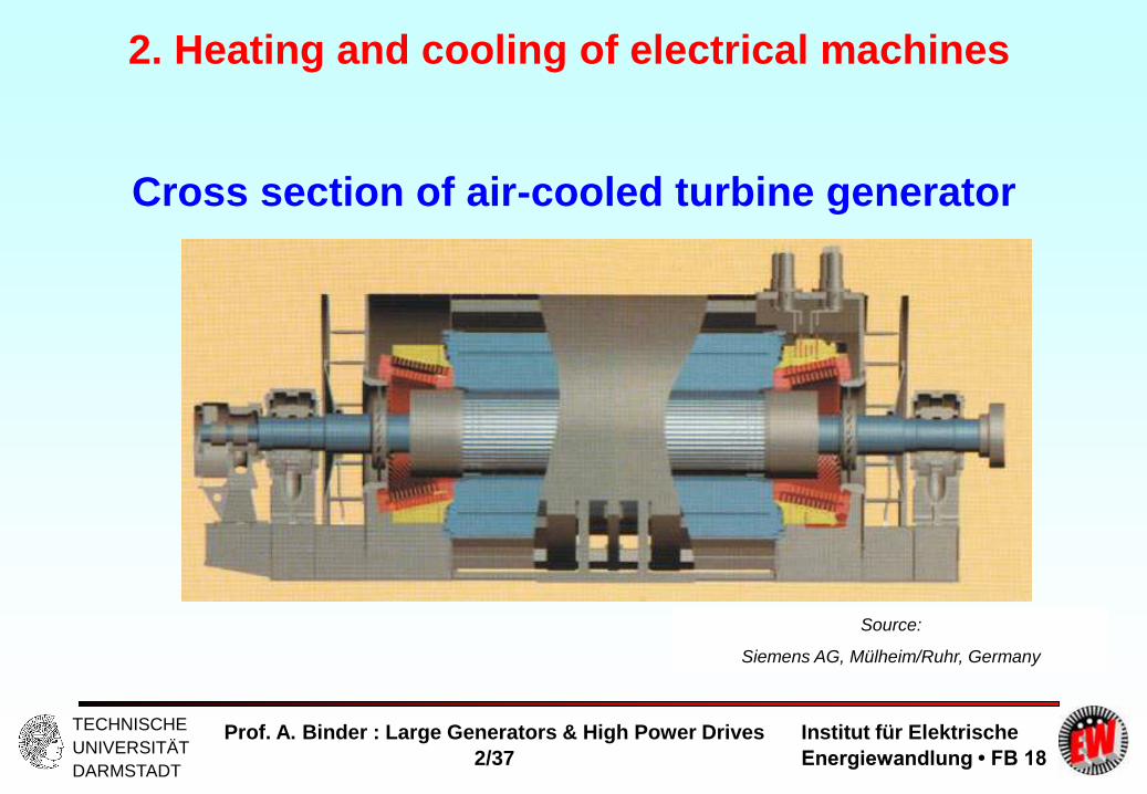
Cross section of air-cooled turbine generator
Source:
Siemens AG, Mülheim/Ruhr, Germany
2. Heating and cooling of electrical machines

Institut für Elektrische
Energiewandlung • FB 18
TECHNISCHE
UNIVERSITÄT
DARMSTADT
Prof. A. Binder : Large Generators & High Power Drives
2/38
Source: Siemens AG, Mülheim/Ruhr, Germany
2. Heating and cooling of electrical machines
Cross section of hydrogen-gas-cooled turbine generator
Closed, sealed
housing

Institut für Elektrische
Energiewandlung • FB 18
TECHNISCHE
UNIVERSITÄT
DARMSTADT
Prof. A. Binder : Large Generators & High Power Drives
2/39
Large Generators and High Power Drives
Summary:
Cooling systems
- Up to 400 MVA air-cooling is possible for turbine generators
- A direct conductor cooling and a stator core section cooling is necessary
- Above 300 MW the needed air flow is too big = too big air friction losses, which
heat up the machine
- Hydrogen gas (at over-pressure) and direct conductor water cooling for higher
rated power
- In salient pole machines: Air and direct conductor water cooling, but no
hydrogen gas cooling (sealing problem für the big machines)

Institut für Elektrische
Energiewandlung • FB 18
TECHNISCHE
UNIVERSITÄT
DARMSTADT
Prof. A. Binder : Large Generators & High Power Drives
2/40
2. Heating and cooling of electrical machines
2.1 Introduction to heating & cooling
2.2 Temperature limits
2.3 Heat sources and loss densities
2.4 Cooling systems
2.5 Coolants
2.6 Basics in fluid dynamics
2.7 Windage losses
2.8 Heat transport by coolant
2.9 Heat transfer
2.10 Conduction of heat
2.11 Efficiency of cooling systems
2.12 Transient heat flow
Source:
BBC, Birr, Switzerland

Institut für Elektrische
Energiewandlung • FB 18
TECHNISCHE
UNIVERSITÄT
DARMSTADT
Prof. A. Binder : Large Generators & High Power Drives
2/41
2. Heating and cooling of electrical machines
2.5 Coolants
Temp-erature
Massdensity
Heatstorage
capability
c
Kinematicviscosity
Thermalcon-
ductivity
Max.electric field
strengthED
°C kg/m3
Ws/(m3K) m
2/s W/(m
.K) kV/m
Air 050
1.2511.058
12601065
13.7.10
-6
18.4.10
-60.0240.027
32003200
Hydrogen100 Vol.-%
050
0.0870.0735
12361056
98.10
-6
126.10
-60.1690.183
19001900
Hydrogen96 Vol.-%
050
0.1340.113
12401060
73.4.10
-6
94.8.10
-60.1560.169
19001900
Helium He 0 0.173 930 107.10
-60.142 1000
Carbon-dioxide CO2
0 1.912 1600 7.2.10
-60.0143 2900
Nitrogen N2 0 1.210 1300 13.6.10
-60.0232 3300
Properties of gaseous coolants

Institut für Elektrische
Energiewandlung • FB 18
TECHNISCHE
UNIVERSITÄT
DARMSTADT
Prof. A. Binder : Large Generators & High Power Drives
2/42
2. Heating and cooling of electrical machines
Cooling with air
Cheap, but must be clean (Filter !). Big velocity necessary for sufficient flow
rate, so big aerodynamic noise. Demand for closed ventilation with heat
exchangers !
Example: Turbine generator: 50 MVA, 3000/min, 85 tons total mass;
cos = 0.8 overexcited, efficiency: = 97.8%
Losses: 40cos outNN PSP MW, 900)1/1( Nd PP kW,
At 50°C: L = 1.058kg/m3, cL = 1065 Ws/m3K,
necessary air flow rate for coolant temperature rise of = 28 K:
30281065
900000
L
d
c
PV m3/s
- 30 m3/s = 115 tons/h = 1.35-times generator mass per hour !
- Closed ventilation necessary !
- Considerable friction losses, so upper machine limit about 400 MVA !

Institut für Elektrische
Energiewandlung • FB 18
TECHNISCHE
UNIVERSITÄT
DARMSTADT
Prof. A. Binder : Large Generators & High Power Drives
2/43
2. Heating and cooling of electrical machines
Cooling with hydrogen gas
Only closed ventilation (danger of explosion, when in contact with oxygen !)
Operation with higher pressure than ambient to avoid penetration of oxygen
into machine: pressure up to 6 bar.
Increased pressure increases heat transfer capability !
Lower friction losses at higher thermal conductivity than air !
So hydrogen gas is used up to 1000 MVA machine unit power !
No feeding of burning of winding (due to partial discharges) due to lack of O2.
Danger of explosion with O2 of air between 4 ... 78 Volume-% H2 in air !
Optimum for explosion is 30 Vol.-% !
Machines usually are operated with 96 ... 99 Vol.-% H2 in air !
Sealing of rotating shaft and of housing necessary !
Before filling the machine it is necessary to expel all residual air by inert gas,
e.g. carbon dioxide CO2 . Same is done in case of emptying machine e.g. for
repair !

Institut für Elektrische
Energiewandlung • FB 18
TECHNISCHE
UNIVERSITÄT
DARMSTADT
Prof. A. Binder : Large Generators & High Power Drives
2/44
2. Heating and cooling of electrical machines
Tem-pera-ture
Massdensity
Heatstorage
capability
c
Kinematicviscosity
Thermalconductivity
Specificelectrical
resistance
el = 1/
°C kg/m3
Ws/(m3K) m
2/s W/(m
.K) m
Water 204060
998992983
4174.10
3
4145.10
3
4123.10
3
1.01.10
-6
0.66.10
-6
0.48.10
-6
0.5980.6270.652
*)
Oil with lowviscosityFlash point 120°C
204060
800785770
1600.10
3
1640.10
3
1670.10
3
5.0.10
-6
3.3.10
-6
2.25.10
-6
0.1470.1430.140
108 ... 10
14
Transformer oilFlash point 140°C
204060
870850840
1760.10
3
1820.10
3
1860.10
3
36.5.10
-6
16.7.10
-6
8.7.10
-6
0.1240.1230.122
108 ... 10
14
Properties of liquid coolants
*) For direct cooling in hollow conductors it is necessary to obtain: (2 … 5) · 103 Ohm.m to avoid electric contact to mass potential

Institut für Elektrische
Energiewandlung • FB 18
TECHNISCHE
UNIVERSITÄT
DARMSTADT
Prof. A. Binder : Large Generators & High Power Drives
2/45
2. Heating and cooling of electrical machines
Cooling with de-ionized water
- Water for cooling electrical winding (at high ele. Potential up to 30 kV) must
have low electrical conductivity ( 5 µS/cm, resp.: 2·103 Ohm.m )
- Water has to be also chemically passive, otherwise corrosion may happen !
- Water has to be de-mineralized, de-ionized, low content of dissolved oxygen !
In case of too high water velocity copper hollow conductors suffer erosion !
In some cases also cavitation may happen !
Thus velocity v has to be limited:
- Maximum water velocity v in copper shall be below ca. 2 m/s,
- in conductors or tubes of non-corrosive steel 3 .. 4 m/s are admissible !

Institut für Elektrische
Energiewandlung • FB 18
TECHNISCHE
UNIVERSITÄT
DARMSTADT
Prof. A. Binder : Large Generators & High Power Drives
2/46
Large Generators and High Power Drives
Summary:
Coolants
- Cheapest coolant: air
- Hydrogen gas: less mass density, less friction losses, higher hat capacity
- Hydrogen gas may „explode“, when in contact with ambient air = overpressure
and hall ventilation system needed
- Direct conductor water cooling needs special non-conducting, clean water
- Very small pump power for water needed due to high mass density and heat
capacity
- Sometimes oil cooling for hollow conductors, but danger of burning
- Oil typically used for transformer cooling due to high break-down field strength
Institut für Elektrische
Energiewandlung • FB 18
TECHNISCHE
UNIVERSITÄT
DARMSTADT
Prof. A. Binder : Large Generators & High Power Drives
2/47
2. Heating and cooling of electrical machines
2.1 Introduction to heating & cooling
2.2 Temperature limits
2.3 Heat sources and loss densities
2.4 Cooling systems
2.5 Coolants
2.6 Basics in fluid dynamics
2.7 Windage losses
2.8 Heat transport by coolant
2.9 Heat transfer
2.10 Conduction of heat
2.11 Efficiency of cooling systems
2.12 Transient heat flow
Source:
BBC, Birr, Switzerland

Institut für Elektrische
Energiewandlung • FB 18
TECHNISCHE
UNIVERSITÄT
DARMSTADT
Prof. A. Binder : Large Generators & High Power Drives
2/48
2. Heating and cooling of electrical machines
2.6 Basics in fluid dynamics
Laminar (viscous) and turbulent flow Flow in tubes :
a) Low velocity: ”parallel” orbits of mass particles due to dominating inner viscous forces
between particles = LAMINAR (VISCOUS) flow
b) High velocity: Orbits of different particles mingled in ”chaotic” way = not only in flow
direction, but also perpendicular: TURBULENT flow
Based on model parameters: REYNOLDS number
vav: average flow velocity
: kinematic viscosity
d: hydraulic diameter of tube
d = 4A/U A,U Cross sectional area / circumference of tube
In straight tubes with smooth surface:
laminar flow: Re < Recr (critical Reynolds number Recr = 2320)
turbulent flow: Re > 3000.
dvav Re
For good heat transfer: Turbulent flow is needed !

Institut für Elektrische
Energiewandlung • FB 18
TECHNISCHE
UNIVERSITÄT
DARMSTADT
Prof. A. Binder : Large Generators & High Power Drives
2/49
2. Heating and cooling of electrical machines
Generation of pressure in fluids by pumps / fans Radial pump / fan:
Generated pressure due to centrifugal force (= radial force)
F on rotating fluid volume between two blades.
- Rotational speed n, angular frequency = 2n), area of
cross section between blades A
- Centrifugal force dF on differential small mass element dm
at radius r :
Increase of pressure between radius r1 and r2:
Pressure difference increases with - mass density
- square of speed
- blade length r2 - r1.
drArdmrdF 22
)(2
21
22
22
1
rrAdFF
r
r
AFp / )(2
21
22
2 rrpV
EULER´s turbine equation
(simplified)

Institut für Elektrische
Energiewandlung • FB 18
TECHNISCHE
UNIVERSITÄT
DARMSTADT
Prof. A. Binder : Large Generators & High Power Drives
2/50
2. Heating and cooling of electrical machines
Pump / fan characteristic
vAV - Flow rate through pump: A: Total cross section, v: velocity
- Pressure drop in pump due to inner friction rises in turbulent flow with square of speed
- Resulting generated pressure difference hence decreases with increased flow rate:
20)( VkpVfp VV
)(2
21
22
20 rrpV
- Pump / fan has to act against pressure drop of
hydraulic system, which also increases with square of
flow rate.
a) Pump generated pressure difference
b) Pressure drop of hydraulic system
B: Operating point of pump / fan
Pump / fan output power PNutz = pV
= Power transferred to fluid to move it !
V

Institut für Elektrische
Energiewandlung • FB 18
TECHNISCHE
UNIVERSITÄT
DARMSTADT
Prof. A. Binder : Large Generators & High Power Drives
2/51
2. Heating and cooling of electrical machines
Radial fan with backward bent blades for a salient pole
synchronous machine
Radial fan,
shaft mounted
Gas inlet
Source: Siemens
AG, Germany

Institut für Elektrische
Energiewandlung • FB 18
TECHNISCHE
UNIVERSITÄT
DARMSTADT
Prof. A. Binder : Large Generators & High Power Drives
2/52
2. Heating and cooling of electrical machines
Generation of pressure in rotor winding
)(2
21
22
2 rrpV
Direct RADIAL cooling of rotor
conductors (Air or hydrogen gas)
Gas inlet
Radial gas outlet
Slot bottom duct
Rotor centre
Source:
Sequenz, H. (Ed.), Springer-Verlag

Institut für Elektrische
Energiewandlung • FB 18
TECHNISCHE
UNIVERSITÄT
DARMSTADT
Prof. A. Binder : Large Generators & High Power Drives
2/53
2. Heating and cooling of electrical machines
Generation of pressure in axial pumps / fans
- No difference in radii at inlet and outlet of pump / fan = no centrifugal force difference
- Generated pressure due to different speed of flow on both sides of blade.
Bernoulli-equation: Subscript 1, 2: Both sides of axial blade
222
21122
221
21 ~2/)(2/2/ vvvppppvpv
- Pressure difference increases with
- mass density
- square of speed
nrvv u 2~
- Circumference speed at radius r is vu: It is proportional to speed of flow along blades v.
2~ npV

Institut für Elektrische
Energiewandlung • FB 18
TECHNISCHE
UNIVERSITÄT
DARMSTADT
Prof. A. Binder : Large Generators & High Power Drives
2/54
2. Heating and cooling of electrical machines
Axial fan for a salient pole synchronous machine
Axial fan Axial fan
Source: Lloyd
Dynamowerk
Bremen, Germany

Institut für Elektrische
Energiewandlung • FB 18
TECHNISCHE
UNIVERSITÄT
DARMSTADT
Prof. A. Binder : Large Generators & High Power Drives
2/55
2. Heating and cooling of electrical machines
Efficiency of fans (ventilators) for gaseous fluids
- Necessary mechanical power at the shaft to drive the fan: PV = PNutz/V
- Ventilator efficiency:
V : 0.1 ... 0.3: simple shaft mounted fans in standard machines for mass production
0.3 ... 0.6: typical shaft mounted fans in bigger machines
0.6 ... 0.85: optimum design for fans (e.g. adjustable blade angle in axial fans,
special contoured blades like in propellers etc.)
Fan / pump characteristic at variable speed n in turbulent flow:
- Pressure drop in pump / fan & in hydraulic system: ~ 2V
- Change of flow rate, generated pressure, power transferred to fluid:
~ n pV ~ n2 PV ~ n3
(necessary for shaft mounted fan in variable speed rives)
V

Institut für Elektrische
Energiewandlung • FB 18
TECHNISCHE
UNIVERSITÄT
DARMSTADT
Prof. A. Binder : Large Generators & High Power Drives
2/56
Computational fluid dynamics
Source:
Siemens AG, Mülheim/Ruhr,
Germany
2. Heating and cooling of electrical machines
- Simulation of coolant gas
particle flow paths via the axial
fan
- Solving of NAVIER-STOKES
equations
- Air velocity up to 30 m/s
- Left: Outlet from the rotor axial
ventilation ducts

Institut für Elektrische
Energiewandlung • FB 18
TECHNISCHE
UNIVERSITÄT
DARMSTADT
Prof. A. Binder : Large Generators & High Power Drives
2/57
2. Heating and cooling of electrical machines
Pressure drop in hydraulic systems (turbulent flow)
- Inner friction of moved fluid causes pressure drop:
- It has to be overcome by pump / fan generated pressure ! Power PNutz = pV
is needed to move fluid against this counter-pressure. Power PNutz is transferred
into heat in fluid.
- Pressure drop at obstacles =
= each deviation from smooth, straight tube geometry:
- Outlet from tubes:
= increasing of cross section of tube, velocity decreases according to continuity of flow in
incompressible fluids:
A2 > A1 :
If A2 >> A1 and sharp edge at outlet: 1 (CARNOT´s law)
2
2~ vpH
V
2
2vpH
2211 vAvAV
1122 // AVvAVv

Institut für Elektrische
Energiewandlung • FB 18
TECHNISCHE
UNIVERSITÄT
DARMSTADT
Prof. A. Binder : Large Generators & High Power Drives
2/58
2. Heating and cooling of electrical machines
Pressure drop at obstacles (turbulent flow)
Inlet into tubes: Shape of tube entrances
Curbed tubes:
Sharp curve round curve
Sharp edge sloped edge rounded edge projecting projecting cone

Institut für Elektrische
Energiewandlung • FB 18
TECHNISCHE
UNIVERSITÄT
DARMSTADT
Prof. A. Binder : Large Generators & High Power Drives
2/59
2. Heating and cooling of electrical machines
Pressure drop in tubes due to friction (turbulent flow)
- Tube with circular or elliptic cross section:
Grade or roughness of inner surface R, length l and hydraulic diameter d
determine pressure drop
a) Smooth copper tubes: Re < 105 (BLASIUS law): R = 0.316 Re –1/4
b) Rough surface tubes: (HOPF & FROMM law): R = 10-2 (k/d)0.314 , d in m
k depends on degree of roughness
- New cast iron or iron tubes: k = 2.5
- Punched out channels in iron stacks: (e.g. d = 0.014 m): R = 0.04
This corresponds with: k = 1.15
2
2v
d
lp RR
15.110
04.0014.0
10
314.0
1
2
314.0
1
2
Rdk

Institut für Elektrische
Energiewandlung • FB 18
TECHNISCHE
UNIVERSITÄT
DARMSTADT
Prof. A. Binder : Large Generators & High Power Drives
2/60
2. Heating and cooling of electrical machines
Total pressure drop in hydraulic system (turbulent flow)
- Total pressure drop = sum of all partial pressure drops in hydraulic system !
- Simplest case: One tube with constant cross section (= constant velocity v) and N
obstacles:
- Varying cross section Ai : Use sectional velocities vi = /Ai !
- Note: In hydraulic systems no superposition law, because non-linear dependence
of pressure drop on speed: p ~ v2 .
- Total pressure drop pres = need of generated pressure by pump / fan !
N
j
jRresd
lvp
1
2
2
V
22
2~
2~ Vvpres

Institut für Elektrische
Energiewandlung • FB 18
TECHNISCHE
UNIVERSITÄT
DARMSTADT
Prof. A. Binder : Large Generators & High Power Drives
2/61
2. Heating and cooling of electrical machines
Different fluids in hydraulic system (turbulent flow)
- Total pressure drop pres :
- Generated pressure difference by shaft-mounted fan:
- With pres = pV mass density cancels:
22
2~
2~ Vvpres
2
2~ npV
)(, fVv
- The flow rate is depending on speed of machine n, but nearly not on type of
gaseous fluid (be it air, H2 etc.)
- Hence it is also independent of static pressure in gas: e.g.: pressure of H2 is 1,
2 or x bar).
- Flow rate and velocity depend on rotor speed:
e.g.: half speed = half flow rate = half fluid velocity !
V
nVv ~,

Institut für Elektrische
Energiewandlung • FB 18
TECHNISCHE
UNIVERSITÄT
DARMSTADT
Prof. A. Binder : Large Generators & High Power Drives
2/62
Large Generators and High Power Drives
Summary:
Basics in fluid dynamics
- For high heat transfer coefficient (HTC) a turbulent flow is needed
- For gaseous coolants axial or radial fans are used
- For liquid coolants centrifugal pumps are used
- Pump or fan power rise with 3rd power of speed (EULER`s turbine equation)
- Non-linear partial differential equations of NAVIER-STOKES describe flow
- Computational fluid dynamics needed for solving NAVIER-STOKES equations
- Simplified for one dimension: BERNOULLI equation
- Flow network based on BERNOULLI equation with flow resistances
- Flow resistances depend on square of flow velocity = non-linear network

Institut für Elektrische
Energiewandlung • FB 18
TECHNISCHE
UNIVERSITÄT
DARMSTADT
Prof. A. Binder : Large Generators & High Power Drives
2/63
2. Heating and cooling of electrical machines
2.1 Introduction to heating & cooling
2.2 Temperature limits
2.3 Heat sources and loss densities
2.4 Cooling systems
2.5 Coolants
2.6 Basics in fluid dynamics
2.7 Windage losses
2.8 Heat transport by coolant
2.9 Heat transfer
2.10 Conduction of heat
2.11 Efficiency of cooling systems
2.12 Transient heat flow
Source:
BBC, Birr, Switzerland

Institut für Elektrische
Energiewandlung • FB 18
TECHNISCHE
UNIVERSITÄT
DARMSTADT
Prof. A. Binder : Large Generators & High Power Drives
2/64
2. Heating and cooling of electrical machines
2.7 Windage losses (= ventilation losses)
- Ventilation losses PVent = sum of
a) Power demand for cooling system: PF (= e.g. fan input power PV)
b) Surface friction losses due to gaseous fluid within machine POR.
PVent = PF + POR
a) Power demand for cooling system: PF = p/
- Different gaseous fluids: PF,G ~ G ~ p Due to law of ideal gases mass density rises with static gas pressure !
V
p / bar 1 2 3 4 5 6
PF,H2 (p)/PF,L1 0.107 0.214 0.320 0.427 0.534 0.641
Compare power demand for: a) Air as coolant at p = 1 bar: power demand: PF,L1
b) Hydrogen gas H2 (96 % Volume percentage, 50 oC) in dependence of static pressure p

Institut für Elektrische
Energiewandlung • FB 18
TECHNISCHE
UNIVERSITÄT
DARMSTADT
Prof. A. Binder : Large Generators & High Power Drives
2/65
2. Heating and cooling of electrical machines
b) Surface friction losses:
Calculation of POR difficult - experimental help needed !
Example:
Rotors of turbine generators:
Long rotating cylinders, surface A = d..l (m2), circumference speed u = d..n
(m/s): Measured losses (kW):
POR = kOR.A.u3
Coefficient kOR : turbulent flow also near surface: kOR ~ G.Re –0.2
Results from experiment at turbine generator rotors, typical air gap widths, static
pressure p = 1 bar: kOR = (1.8 ... 3 ... 4) · 10-6 kWs3/m5.
(depending on roughness of rotor surface !)
Surface friction losses

Institut für Elektrische
Energiewandlung • FB 18
TECHNISCHE
UNIVERSITÄT
DARMSTADT
Prof. A. Binder : Large Generators & High Power Drives
2/66
2. Heating and cooling of electrical machines
Coolant gas influence on surface friction losses
- Influence of gas parameters and static pressure on POR :
- mass density G ~ p ,
- kinematic viscosity: ~ 1/p
Compare surface friction losses for:
a) Air as coolant at p = 1 bar: POR,L1
b) Hydrogen gas H2 (96 % Volume percentage, 50 oC) in dependence of static
pressure p
8.02.0, ~~ pP GGGOR
p / bar 1 2 3 4 5 6
POR,H2(p)/POR,L1 0.148 0.258 0.357 0.449 0.537 0.622

Institut für Elektrische
Energiewandlung • FB 18
TECHNISCHE
UNIVERSITÄT
DARMSTADT
Prof. A. Binder : Large Generators & High Power Drives
2/67
Large Generators and High Power Drives
Summary:
Windage losses
- Friction of moved gaseous coolant on machine surfaces leads to heat
- Big surface in big machines = dominant windage losses
- Section cooling to increase heat transfer at limited coolant flow

Institut für Elektrische
Energiewandlung • FB 18
TECHNISCHE
UNIVERSITÄT
DARMSTADT
Prof. A. Binder : Large Generators & High Power Drives
2/68
2. Heating and cooling of electrical machines
2.1 Introduction to heating & cooling
2.2 Temperature limits
2.3 Heat sources and loss densities
2.4 Cooling systems
2.5 Coolants
2.6 Basics in fluid dynamics
2.7 Windage losses
2.8 Heat transport by coolant
2.9 Heat transfer
2.10 Conduction of heat
2.11 Efficiency of cooling systems
2.12 Transient heat flow
Source:
BBC, Birr, Switzerland

Institut für Elektrische
Energiewandlung • FB 18
TECHNISCHE
UNIVERSITÄT
DARMSTADT
Prof. A. Binder : Large Generators & High Power Drives
2/69
2. Heating and cooling of electrical machines
2.8 Heat transport by coolant
Coolant flow is heated up by losses Pd and
increases its temperature:
Temperature rise:
Heat (losses Pd ) is transferred to outside
cooler via convection !
Vc
Pd
- Typical temperature rise of coolant in machine
(indirect cooled machines): = 15...35(40) K .
- Typical maximum inlet temperature: 40 °C.
- Direct cooling: Maximum outlet temperature: Gases: 110oC/130oC Thermal Class B/F,
Liquids: H2O or Oil: 85oC
in
out

Institut für Elektrische
Energiewandlung • FB 18
TECHNISCHE
UNIVERSITÄT
DARMSTADT
Prof. A. Binder : Large Generators & High Power Drives
2/70
2. Heating and cooling of electrical machines
Hollow rotor conductors of turbine generators directly
cooled with hydrogen gas
Vc
Pd
Rotor slot:
7 turns per coil
elliptic duct cross
section
Linear temperature rise along
conductor
Source:
BBC, Birr, Switzerland

Institut für Elektrische
Energiewandlung • FB 18
TECHNISCHE
UNIVERSITÄT
DARMSTADT
Prof. A. Binder : Large Generators & High Power Drives
2/71
2. Heating and cooling of electrical machines
2 GW generator with test field exciter slip rings in the test bay
Source: Siemens, Germany
Tested efficiency:
98.98% at 1992 MVA,
cos = 0.9 cap.
(with exciter)
Stator winding:
outlet water
temperature:
tested:
1992 MVA: 68°C
calculated:
2222 MVA: 74°C
Limit: 90°C
Cold water inlet: 45°C

Institut für Elektrische
Energiewandlung • FB 18
TECHNISCHE
UNIVERSITÄT
DARMSTADT
Prof. A. Binder : Large Generators & High Power Drives
2/72
2 GW generator: Stator calculated temperature distribution
Stator Roebel bars, hollow copper
conductors, direct water cooling
Different upper and lower bar
Source:
Siemens,
Germany
Calc. temperatures of stator conductors at
2200 MVA, 27 kV, cos = 0.9 cap.
Water in top bar
Copper: Top bar
Water in bottom bar
Copper: Bottom bar
Water temperature limit
0 2 4 6 8 10
Distance along bar from water inlet (m)
Tem
pera
ture
°C
90
80
70
60
50
Inlet: 45
2. Heating and cooling of electrical machines
Institut für Elektrische
Energiewandlung • FB 18
TECHNISCHE
UNIVERSITÄT
DARMSTADT
Prof. A. Binder : Large Generators & High Power Drives
2/73
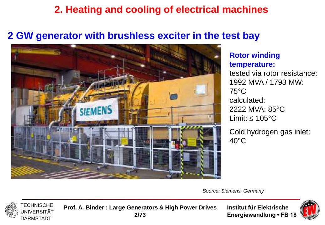
2 GW generator with brushless exciter in the test bay
Source: Siemens, Germany
Rotor winding
temperature:
tested via rotor resistance:
1992 MVA / 1793 MW:
75°C
calculated:
2222 MVA: 85°C
Limit: 105°C
Cold hydrogen gas inlet:
40°C
2. Heating and cooling of electrical machines

Institut für Elektrische
Energiewandlung • FB 18
TECHNISCHE
UNIVERSITÄT
DARMSTADT
Prof. A. Binder : Large Generators & High Power Drives
2/74
2 GW generator: Rotor calculated temperature distribution
Rotor hollow copper
conductors, direct
hydrogen gas cooling
Source:
Siemens,
Germany
Calc. temperatures of rotor conductors
at 2200 MVA, 27 kV, cos = 0.9 cap.
Top conductor end
Top conductor embedded
Bottom conductor end
Bottom conductor embedded
Copper temperature limit
-1 0 1 2 3 4
Distance along bar from rotor body end (m)
Tem
pera
ture
°C
130
110
90
80
70
60
120
Rotor
front end Rotor
center line
Average temperature: (100+60)/2 = 80°C
2. Heating and cooling of electrical machines

Institut für Elektrische
Energiewandlung • FB 18
TECHNISCHE
UNIVERSITÄT
DARMSTADT
Prof. A. Binder : Large Generators & High Power Drives
2/75
Large Generators and High Power Drives
Summary:
Heat transport by coolant
- Temperature variation along the hollow conductors
- HOT SPOT temperature decisive for insulation life span
- Rotor field winding is hottest at over-excited operation due to high DC field
current
Institut für Elektrische
Energiewandlung • FB 18
TECHNISCHE
UNIVERSITÄT
DARMSTADT
Prof. A. Binder : Large Generators & High Power Drives
2/76
2. Heating and cooling of electrical machines
2.1 Introduction to heating & cooling
2.2 Temperature limits
2.3 Heat sources and loss densities
2.4 Cooling systems
2.5 Coolants
2.6 Basics in fluid dynamics
2.7 Windage losses
2.8 Heat transport by coolant
2.9 Heat transfer
2.10 Conduction of heat
2.11 Efficiency of cooling systems
2.12 Transient heat flow
Source:
BBC, Birr, Switzerland

Institut für Elektrische
Energiewandlung • FB 18
TECHNISCHE
UNIVERSITÄT
DARMSTADT
Prof. A. Binder : Large Generators & High Power Drives
2/77
2. Heating and cooling of electrical machines
2.9 Heat transfer a) Radiation
Small effect, as usually < 100 K between machine surface and
ambient: S 7 W/(m2K).
b) Convection:
Coolant is heated up, transports off the heat by its movement !
Hot surface: temperature W, cool coolant: temperature KM
Surface: A, heat flow: Pd !
Heat transfer coefficient of convection: K
Free (natural) convection: Lower mass density of hot coolant
gives rise to coolant circulation : K 7 W/(m2K)
In this case radiation has to be considered: K + S = 15 W/(m2 K)
)( KMWKd AP
Institut für Elektrische
Energiewandlung • FB 18
TECHNISCHE
UNIVERSITÄT
DARMSTADT
Prof. A. Binder : Large Generators & High Power Drives
2/78
2. Heating and cooling of electrical machines
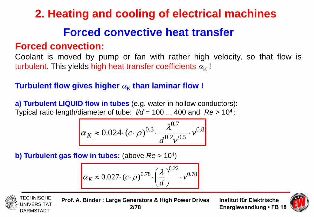
Forced convective heat transfer
Forced convection: Coolant is moved by pump or fan with rather high velocity, so that flow is
turbulent. This yields high heat transfer coefficients K !
Turbulent flow gives higher K than laminar flow !
a) Turbulent LIQUID flow in tubes (e.g. water in hollow conductors):
Typical ratio length/diameter of tube: l/d = 100 ... 400 and Re > 104 :
b) Turbulent gas flow in tubes: (above Re > 104)
8.0
5.02.0
7.03.0)(024.0 v
dcK
78.022.0
78.0)(027.0 vd
cK

Institut für Elektrische
Energiewandlung • FB 18
TECHNISCHE
UNIVERSITÄT
DARMSTADT
Prof. A. Binder : Large Generators & High Power Drives
2/79
2. Heating and cooling of electrical machines
Heat transfer coefficient for turbulent LIQUID flow in tubes at 40°C
a) special low-viscous oil b) water

Institut für Elektrische
Energiewandlung • FB 18
TECHNISCHE
UNIVERSITÄT
DARMSTADT
Prof. A. Binder : Large Generators & High Power Drives
2/80
2. Heating and cooling of electrical machines
Heat transfer coefficient for turbulent AIR flow in tubes at 50°C
Static
pressure:
1 bar

Institut für Elektrische
Energiewandlung • FB 18
TECHNISCHE
UNIVERSITÄT
DARMSTADT
Prof. A. Binder : Large Generators & High Power Drives
2/81
2. Heating and cooling of electrical machines
Heat transfer coefficient for different gases in
tubes at 50°C
For other gases than air heat transfer coefficient changes due to
and ~ p with:
Compare heat transfer coefficient (HTC) for:
a) Air as coolant at p = 1 bar: HTC: K,L1
b) Hydrogen gas H2 (96 % Volume percentage, 50 oC) in dependence of static
pressure p
78.022.0
78.0)(027.0 vd
cK
78.022.078.0 ~)(~ pcK
p / bar 1 2 3 4 5 6
KH2(p)/ KL1 1.49 2.56 3.51 4.40 5.23 6.03

Institut für Elektrische
Energiewandlung • FB 18
TECHNISCHE
UNIVERSITÄT
DARMSTADT
Prof. A. Binder : Large Generators & High Power Drives
2/82
2. Heating and cooling of electrical machines
Heat transfer coefficient (HTC) for salient pole
synchronous machines in turbulent air flow
Rotor circumference speed u = dr..n :
HTC is in case b) virtually increased due to
bigger cooling surface A !
Flat copper coils Flat copper coils with cooling fins
In case b) surface A is increased! Taking surface A of case
a), therefore bigger HTC has to be used !
u Source:
BBC, Birr, Switzerland

Institut für Elektrische
Energiewandlung • FB 18
TECHNISCHE
UNIVERSITÄT
DARMSTADT
Prof. A. Binder : Large Generators & High Power Drives
2/83
2. Heating and cooling of electrical machines
“Cooling fins” by broader copper turns in salient pole
excitation winding
Flat copper coils with cooling fins Source: VATech Hydro (now Andritz Hydro), Austria

Institut für Elektrische
Energiewandlung • FB 18
TECHNISCHE
UNIVERSITÄT
DARMSTADT
Prof. A. Binder : Large Generators & High Power Drives
2/84
2. Heating and cooling of electrical machines
Summary: Heat transfer coefficients (W/(m2K))
Natural convection Forced convection
15 Air 50 ... 300
Hydrogen gas 100 ... 1500
Oil 500 ... 2000
Water 5000 ... 20000

Institut für Elektrische
Energiewandlung • FB 18
TECHNISCHE
UNIVERSITÄT
DARMSTADT
Prof. A. Binder : Large Generators & High Power Drives
2/85
2. Heating and cooling of electrical machines
Comparison of hydrogen gas and air as coolant a) Air as coolant at p = 1 bar
b) Hydrogen gas H2 (96 % Volume percentage, 50 oC) in dependence of static
pressure p
a) Power demand for cooling system:
b) Surface friction losses:
c) Heat transfer coefficient:
d) Specific heat capacity:
p / bar 1 2 3 4 5 6
PF,H2 (p)/PF,L1 0.107 0.214 0.320 0.427 0.534 0.641
POR,H2(p)/POR,L1 0.148 0.258 0.357 0.449 0.537 0.622
KH2(p)/ KL1 1.49 2.56 3.51 4.40 5.23 6.03
cH2(p)/ cL1 1 2 3 4 5 6

Institut für Elektrische
Energiewandlung • FB 18
TECHNISCHE
UNIVERSITÄT
DARMSTADT
Prof. A. Binder : Large Generators & High Power Drives
2/86
Large Generators and High Power Drives
Summary:
Heat transfer
- Heat transfer coefficient (HTC) due to convective cooling
- HTC depends on coolant type and increases with coolant velocity
- Liquids (e.g. water) have much higher HTC than gaseous coolants
- Increase of temperature difference from hot part to coolant increase heat
transfer
- Increase of cooling surface increases convective heat transfer

Institut für Elektrische
Energiewandlung • FB 18
TECHNISCHE
UNIVERSITÄT
DARMSTADT
Prof. A. Binder : Large Generators & High Power Drives
2/87
2. Heating and cooling of electrical machines
2.1 Introduction to heating & cooling
2.2 Temperature limits
2.3 Heat sources and loss densities
2.4 Cooling systems
2.5 Coolants
2.6 Basics in fluid dynamics
2.7 Windage losses
2.8 Heat transport by coolant
2.9 Heat transfer
2.10 Conduction of heat
2.11 Efficiency of cooling systems
2.12 Transient heat flow
Source:
BBC, Birr, Switzerland

Institut für Elektrische
Energiewandlung • FB 18
TECHNISCHE
UNIVERSITÄT
DARMSTADT
Prof. A. Binder : Large Generators & High Power Drives
2/88
2. Heating and cooling of electrical machines
2.10 Conduction of heat
)/,/,/( zyxgradq - Fourier´s law of conduction of heat:
- Heating up of mass element dm: AdxxqAxqdVxpdtxdcdm xxd )()()()/)((
xxqxpdtxdc xd /)()()/)((
- Combining both laws:
- For three co-ordinates x, y, z:
22 /)()()/)(( xxxpdtxdc d
2
2
2
2
2
2
),,(zyx
zyxpt
c zyxd
- Partial differential equation of „heat transportation“ in thermally conductive media
with anisotropy: Solution: (x,y,z,t ): „Time-varying“ temperature field !

Institut für Elektrische
Energiewandlung • FB 18
TECHNISCHE
UNIVERSITÄT
DARMSTADT
Prof. A. Binder : Large Generators & High Power Drives
2/89
2. Heating and cooling of electrical machines
Special cases of conduction of heat
),,(2
2
2
2
2
2
zyxpzyx
dzyx
02
2
2
2
2
2
zyx
a) Stationary temperature field (no dependence on time: d./dt = 0):
(POISSON equation).
b) Isotropy of material (= x = y = z), no heat sources: (pd = 0) :
LAPLACE equation:
- Partial differential equation of „heat transportation“ in thermally conductive media
with isotropy: Solution: (x,y,z): „Time-invariant“ temperature field !

Institut für Elektrische
Energiewandlung • FB 18
TECHNISCHE
UNIVERSITÄT
DARMSTADT
Prof. A. Binder : Large Generators & High Power Drives
2/90
2. Heating and cooling of electrical machines Metals (W/mK) Insulating (W/mK)
materialsCast iron 30... 46 Glass 0.8 ... 1.2Steel 40... 46 Asbestos ca. 0.2Nirosta Steel 25... 30 Mica 0.4 ... 0.6Non-magnetic steel 14... 16 Paper 0.05...0.15Si-alloy steel sheets 15... 48 Polyamide-paper (Nomex) ca. 0.13Pure “electrolytic” copper ca. 390 Pressed wood 0.08...0.2“Technical” copper ca. 380 Wood 0.14...0.3Brass ca. 110 Hard board 0.23...0.28Bronze ca. 100 Mica foil HV insulation 0.15...0.2Zinc ca. 110 Mica-Resin compound 0.2 ... 0.3Lead ca. 35 Epoxy resin 0.17...0.23Pure aluminium ca. 220 Resin impregnated
press board 0.2 ... 0.5Aluminium alloys 100...190 Teflon 0.2 ... 0.24
At 50o C. At 50o C.At 100o C : By ca. 1...2 % lower At 100o C: Increase by ca. 10%.

Institut für Elektrische
Energiewandlung • FB 18
TECHNISCHE
UNIVERSITÄT
DARMSTADT
Prof. A. Binder : Large Generators & High Power Drives
2/91
2. Heating and cooling of electrical machines
Law of Wiedemann-Franz-Lorenz
- Pure metals: Temperature is proportional to kinetic energy of
“free” electrons = Conduction of heat (Fourier´s law) is done by
moving free electrons.
As current flow ( = conduction of electric charges (Ohm´s law)) is
also done by “free” electrons, both laws are similar:
Electric and thermal conductivity are proportional: ~
gradEJ
gradq
Copper Pure aluminium Pure iron
/ S/m (at 20°C) 57.106 (100%) 34.106 (60%) 10.106 (18%)
/ W/(m.K) (50°C) 380 (100%) 220 (58%) 48 (13%)

Institut für Elektrische
Energiewandlung • FB 18
TECHNISCHE
UNIVERSITÄT
DARMSTADT
Prof. A. Binder : Large Generators & High Power Drives
2/92
2. Heating and cooling of electrical machines
)/( xqx
One-dimensional heat conduction in a plate
Plate: Thickness , area A, heat flow q.A = P
A
P
dx
d
dx
d
A
Pq
Boundary condition: at x = 0 is = (0):
Result:
xA
Px
)0()(
- Linear drop of temperature in the plate !
- OHM´s law of heat conduction:
- Thermal resistance:
PR
AR

Institut für Elektrische
Energiewandlung • FB 18
TECHNISCHE
UNIVERSITÄT
DARMSTADT
Prof. A. Binder : Large Generators & High Power Drives
2/93
2. Heating and cooling of electrical machines
Temperature drop in slot main insulation
Índirectly cooled rotor winding of
turbine generator. Temperature
drop at main insulation, teeth, rotor
surface, and in air gap air flow. Source:
Neidhöfer, G., ABB, Switzerland

Institut für Elektrische
Energiewandlung • FB 18
TECHNISCHE
UNIVERSITÄT
DARMSTADT
Prof. A. Binder : Large Generators & High Power Drives
2/94
2. Heating and cooling of electrical machines
- Example: Two plates of different material = laminated structure- Two thermal resistances R1 und R2, - identical area A = series connection of thermal resistances
2
2
1
11
ARres
- Equivalent structure of total thickness = 1 + 2 :
res
resA
R
211
- Equivalent thermal conductivity res :
2
2
1
1
21
res with N layers:
N
i i
i
N
i
i
res
1
1
Heat conduction in laminated structure
Institut für Elektrische
Energiewandlung • FB 18
TECHNISCHE
UNIVERSITÄT
DARMSTADT
Prof. A. Binder : Large Generators & High Power Drives
2/95
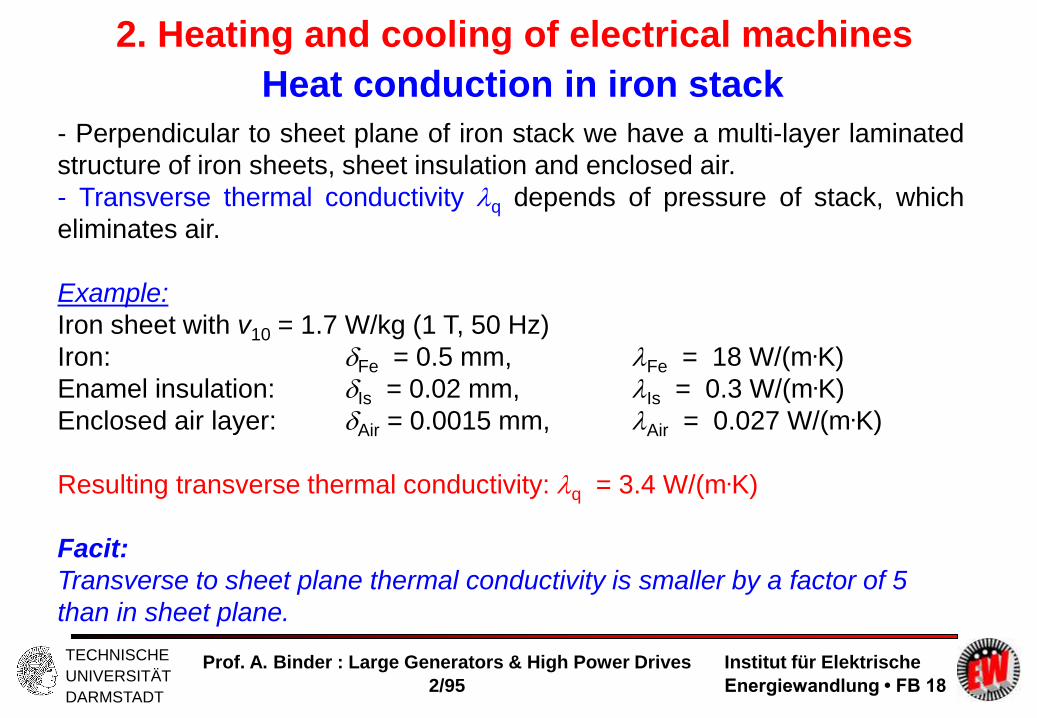
2. Heating and cooling of electrical machines
- Perpendicular to sheet plane of iron stack we have a multi-layer laminated
structure of iron sheets, sheet insulation and enclosed air.
- Transverse thermal conductivity q depends of pressure of stack, which
eliminates air.
Example:
Iron sheet with v10 = 1.7 W/kg (1 T, 50 Hz)
Iron: Fe = 0.5 mm, Fe = 18 W/(m.K)
Enamel insulation: Is = 0.02 mm, Is = 0.3 W/(m.K)
Enclosed air layer: Air = 0.0015 mm, Air = 0.027 W/(m.K)
Resulting transverse thermal conductivity: q = 3.4 W/(m.K)
Facit:
Transverse to sheet plane thermal conductivity is smaller by a factor of 5
than in sheet plane.
Heat conduction in iron stack

Institut für Elektrische
Energiewandlung • FB 18
TECHNISCHE
UNIVERSITÄT
DARMSTADT
Prof. A. Binder : Large Generators & High Power Drives
2/96
2. Heating and cooling of electrical machines
Axial temperature distribution in iron stack (1)
02
2
Cxp
dx
dp
dx
d
Iron losses are distributed heat source in iron stack pd !
1st integration:
1. boundary condition:No heat flow at symmetry line x = 0 :
00)0( 0
0
Cdx
dq
x
2nd integration:
1
2
2)( C
xpx
2. boundary condition: )()(
2)(
2
1
pC

Institut für Elektrische
Energiewandlung • FB 18
TECHNISCHE
UNIVERSITÄT
DARMSTADT
Prof. A. Binder : Large Generators & High Power Drives
2/97
2. Heating and cooling of electrical machines
Axial temperature distribution in iron stack
Solution: Parabolic axial temperature distribution:
Maximum in middle of stack at x = 0:
22
2)()( x
px
At large stack lengths temperature rise in
the middle is high
- due to parabolic temperature distribution
- due to low q = l/5 !
Necessity to segment the stack with radial
ventilation ducts !

Institut für Elektrische
Energiewandlung • FB 18
TECHNISCHE
UNIVERSITÄT
DARMSTADT
Prof. A. Binder : Large Generators & High Power Drives
2/98
Large Generators and High Power Drives
Summary:
Conduction of heat
- Partial differential equation for temperature distribution
- Simplification for one-dimensional heat flow = FOURIER´s law of heat
conduction
- WIEDEMANN-FRANZ-LORENZ law for metals:
A good electrical conductor is also a good thermal conductor
- Electrical insulation is also thermally insulating
- Temperature drop from inner parts to outer cooled boundaries
- In big machines : Big dimensions = big temperature drop
- Segmentation of cores with radial cooling ducts to reduce temperature drop

Institut für Elektrische
Energiewandlung • FB 18
TECHNISCHE
UNIVERSITÄT
DARMSTADT
Prof. A. Binder : Large Generators & High Power Drives
2/99
2. Heating and cooling of electrical machines
2.1 Introduction to heating & cooling
2.2 Temperature limits
2.3 Heat sources and loss densities
2.4 Cooling systems
2.5 Coolants
2.6 Basics in fluid dynamics
2.7 Windage losses
2.8 Heat transport by coolant
2.9 Heat transfer
2.10 Conduction of heat
2.11 Efficiency of cooling systems
2.12 Transient heat flow
Source:
BBC, Birr, Switzerland

Institut für Elektrische
Energiewandlung • FB 18
TECHNISCHE
UNIVERSITÄT
DARMSTADT
Prof. A. Binder : Large Generators & High Power Drives
2/100
2. Heating and cooling of electrical machines
2.11 Efficiency of cooling systems
a) „Specific heat capacity“:
v : gases 50 m/s, H2O in Cu-hollow conductors 1.5 m/s
b) Convection: HTC: K
v see a): hydraulic diameter d = 0.01 m
c) Power demand:
vAcP "" vc
KK OP
resresd
resF vc
vc
PpVP
22 1
~1
2/
c / Ws/(m3K) / kg/m3 v / m/s res
Water, 60°C 4123.103983 1.5 150
Air, 50°C 1065 1.058 30 10
PF,H2O/PF,L = 0.009 = 0.9%

Institut für Elektrische
Energiewandlung • FB 18
TECHNISCHE
UNIVERSITÄT
DARMSTADT
Prof. A. Binder : Large Generators & High Power Drives
2/101
2. Heating and cooling of electrical machines
Coolant Material data Cooling effect Power demand
Per unit ofeffect of
AIR
Massdensity
Specificheat
Specificheat
transfer
Heattransfer
coefficient
Fan power Surfacefrictionlosses
/L c / (c)L cv / (cv)L K / K,L PF / PF,L POR / POR,L
Air, 1 bar 1.0 1.0 1.0 1.0 1.0 1.0
H2, 96% 1 bar2 bar4 bar
0.1070.2140.427
1.0
2.0
4.0
1.0
2.0
4.0
1.492.564.40
0.1070.2140.427
0.1480.2580.449
He, 1 bar 0.138 0.74 0.74 1.17 0.138 0.209
CO2, 1 bar 1.528 1.27 1.27 1.08 1.528 1.344
N2, 1 bar 0.967 1.03 1.03 1.02 0.967 0.966
Water 935 3880 116 43 0.1...1% Given by airgap gas
Low viscousoil
740 1550 47 5 0.1...1% Given by airgap gas

Institut für Elektrische
Energiewandlung • FB 18
TECHNISCHE
UNIVERSITÄT
DARMSTADT
Prof. A. Binder : Large Generators & High Power Drives
2/102
Large Generators and High Power Drives
Summary:
Efficiency of cooling systems
- Hydrogen gas far more effective for better heat transfer and lower friction than
air, but explosive
- Hydrogen gas heat transfer increases with increased hydrogen gas pressure
- Water as liquid coolant has highest effect on heat transfer, but must be non-
conductive and „clean“

Institut für Elektrische
Energiewandlung • FB 18
TECHNISCHE
UNIVERSITÄT
DARMSTADT
Prof. A. Binder : Large Generators & High Power Drives
2/103
2. Heating and cooling of electrical machines
2.1 Introduction to heating & cooling
2.2 Temperature limits
2.3 Heat sources and loss densities
2.4 Cooling systems
2.5 Coolants
2.6 Basics in fluid dynamics
2.7 Windage losses
2.8 Heat transport by coolant
2.9 Heat transfer
2.10 Conduction of heat
2.11 Efficiency of cooling systems
2.12 Transient heat flow
Source:
BBC, Birr, Switzerland

Institut für Elektrische
Energiewandlung • FB 18
TECHNISCHE
UNIVERSITÄT
DARMSTADT
Prof. A. Binder : Large Generators & High Power Drives
2/104
2. Heating and cooling of electrical machines
2.12 Transient heat flow
Heat balance for mass M during time interval dt :
P .dt = ( - 0).dt/R + M .c.d
Losses heat transfer to ambient stored heat in body
Differential equation:
with concentrated elements: C = M.c, R =1/(K.A)
+ C.R. d/dt = 0 + P.R
Corresponding partial differential equation
for distributed material properties:
2
2
2
2
2
2
),,(zyx
zyxpt
c zyxd
„homogeneous-body“ replica

Institut für Elektrische
Energiewandlung • FB 18
TECHNISCHE
UNIVERSITÄT
DARMSTADT
Prof. A. Binder : Large Generators & High Power Drives
2/105
2. Heating and cooling of electrical machines
Heating up & cooling down
)1()()( /00
Tts et 0
/)( Ttet
Thermal time constant of „homogeneous-body“ replica T = C.R = M .c/(K .A)
Steady state temperature rise: s = P.R = P/(K .A)
Adiabatic heating = no heat exchange
= tangent to temperature rise curve: Mc
P
Tdt
d s
t
0
0

Institut für Elektrische
Energiewandlung • FB 18
TECHNISCHE
UNIVERSITÄT
DARMSTADT
Prof. A. Binder : Large Generators & High Power Drives
2/106
2. Heating and cooling of electrical machines
Adiabatic heating
Adiabatic heating = no heat exchange = tangent to temperature rise curve:
Differential equation: C = M .c, R is infinite = T is infinite
C.d( - 0)/dt = P Solution: - 0 = P/C.t
Application: Short time overload:
Duration t much shorter than T, so T is regarded
as infinite.
Example:Conductor: Volume V: Rated current density: J0 , at overload: J1
Additional losses in conductor at overload:
VJJPP )( 2
02101
Temperature rise due to heat capacity: C = cV:
c
JJ
dt
d
t
20
21
0

Institut für Elektrische
Energiewandlung • FB 18
TECHNISCHE
UNIVERSITÄT
DARMSTADT
Prof. A. Binder : Large Generators & High Power Drives
2/107
2. Heating and cooling of electrical machines
Intermittent periodic duty S3
Load Load Load Load ...............
No-load No-load No-load ...............
Institut für Elektrische
Energiewandlung • FB 18
TECHNISCHE
UNIVERSITÄT
DARMSTADT
Prof. A. Binder : Large Generators & High Power Drives
2/108
2. Heating and cooling of electrical machines
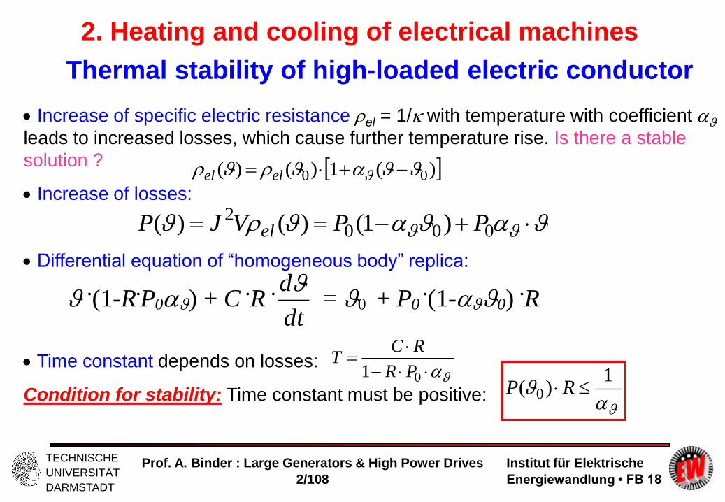
Thermal stability of high-loaded electric conductor
Increase of specific electric resistance el = 1/ with temperature with coefficient
leads to increased losses, which cause further temperature rise. Is there a stable
solution ?
Increase of losses:
Differential equation of “homogeneous body” replica:
Time constant depends on losses:
Condition for stability: Time constant must be positive:
)(1)()( 00 elel
0002 )1()()( PPVJP el
.(1-R
.P0) + C
.R
.
dt
d = 0 + P0
.(1-0)
.R
01 PR
RCT
1)( 0 RP

Institut für Elektrische
Energiewandlung • FB 18
TECHNISCHE
UNIVERSITÄT
DARMSTADT
Prof. A. Binder : Large Generators & High Power Drives
2/109
2. Heating and cooling of electrical machines
Thermal instability
1)( 0 RP
- In case of too big losses:
Time constant gets negative T < 0, so solution yields exponential increase of
temperature rise !
- Solution for T < 0:
Example:
Cu-conductor: ( = 1/255 1/K, at 0 = 20°C)
Overload losses P at 20o C must be below a value, which would lead to
stationary temperature rise of 1/ = 255 K !
Otherwise: Fuse effect: Copper conductor over-heats and evaporates !
)(//00 ~)1()()( TabstTt
s eet

Institut für Elektrische
Energiewandlung • FB 18
TECHNISCHE
UNIVERSITÄT
DARMSTADT
Prof. A. Binder : Large Generators & High Power Drives
2/110
Large Generators and High Power Drives
Summary:
Transient heat flow
- Transient partial differential equation for diffusion of heat leads to transient
temperature distribution
- Simplification: Lumped mass/heat-capacity elements lead to a lumped
parameter (C-R) network
- Electrical analogy: Capacitor-resistor network
- Single mass model = single body equivalent = one thermal time constant
- Multi-mass model = proportional increase of time constants
- Model wit two masses = two time constants (e.g. short time constant due to
copper winding, long time constant due to iron core with big mass)
- Duty cycle determines temperature variation
- Thermal instability limit in electrical machines usually far above the Thermal
Class temperature limit