large format digital dc shunt ammeter · 2019-06-13 · current ranges: the ammeter uses 5 switches...
TRANSCRIPT

DMS01-AM Series Large Format Digital DC Shunt Ammeter
DMS01-AM.A01.D06 Page 1 of 7
www.murata-ps.com/support
PRODUCT OVERVIEW DMS01-AM-RS12-C is a robust, highly configurable, digital panel meter that provides precise measurement and display of DC current and supports a wide range of external shunts. DIP switches simplify selection and setup of shunt current / voltage input ranges and features a highly visible red 1” (25mm) tall, 3½ – 4½ digit seven-segment LED display with adjustable brightness. Independent offset and scale adjustment trim-potentiometers optimize precision for specialized applications and the internal digital filter enhances performance in electrically noisy environments. An external 12VDC power source provides power to the meter. An internal DC-DC converter accommodates a ±48V common-mode measurement range with respect to the power supply input and supports both high or low side measurement, simplifying a wide range of measurement applications. This digital panel meter ideal for laboratory instrumentation, factory automation, and any application that requiring precise current monitoring.
ORDERING INFORMATION DMS01-AM-RS12-C Digital DC Shunt Ammeter, 1” Red Display, 12VDC Power
ACCESSORIES Shunts
Murata Model # Full-scale Amps / Output Voltage Resistance (mΩs at 25˚C)
3020-01097-0 5A / 50mV 10.0000 3020-01107-0 10A / 100mV 10.0000 3020-01098-0 20A / 50mV 2.5000 3020-01096-0 50A / 50mV 1.0000 3020-01099-0 100A / 50mV 0.5000 3020-01108-0 100A / 100mV 1.0000 3020-01100-0 150A / 50mV 0.3300 3020-01101-0 200A / 50mV 0.2500 3020-01102-0 300A / 50mV 0.1670 3020-01103-0 500A / 50mV 0.1000 3020-01104-0 800A / 50mV 0.0625 3020-01105-0 1000A / 50mV 0.0500 3020-01106-0 1200A / 50mV 0.0417
SIMPLIFIED BLOCK DIAGRAM
Features
Measures ranges of 1A to 1200A 0.2% typical accuracy Supports user selectable 50 or 100 mV
external shunts Bright 1” red LED display, readable at
distance of 80 feet (~24 m) Adjustable display brightness Wide common-mode input range (±48V) Digital filter for optimizing measurements in
electrically noisy environments Operates from an external 12VDC power
supply Mounts with adhesive strips (supplied) or
screws
For full details go to www.murata-ps.com/rohs
DMS01-AM Series Large Format Digital DC Shunt Ammeter
DMS01-AM.A01.D06 Page 2 of 7
www.murata-ps.com/support
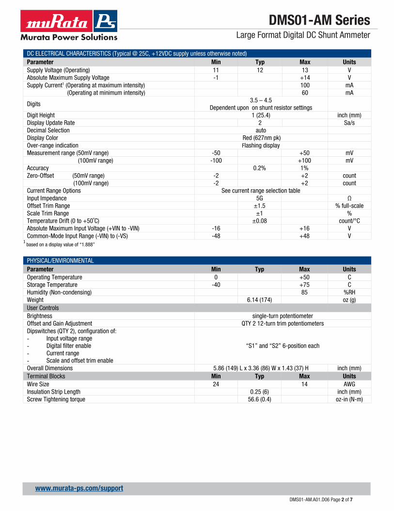
DC ELECTRICAL CHARACTERISTICS (Typical @ 25C, +12VDC supply unless otherwise noted) Parameter Min Typ Max Units Supply Voltage (Operating) 11 12 13 V Absolute Maximum Supply Voltage -1 +14 V Supply Current1 (Operating at maximum intensity) 100 mA (Operating at minimum intensity) 60 mA
Digits 3.5 – 4.5
Dependent upon on shunt resistor settings
Digit Height 1 (25.4) inch (mm) Display Update Rate 2 Sa/s Decimal Selection auto Display Color Red (627nm pk) Over-range indication Flashing display Measurement range (50mV range) -50 +50 mV (100mV range) -100 +100 mV Accuracy 0.2% 1% Zero-Offset (50mV range) -2 +2 count (100mV range) -2 +2 count Current Range Options See current range selection table Input Impedance 5G Ω Offset Trim Range ±1.5 % full-scale Scale Trim Range ±1 % Temperature Drift (0 to +50˚C) ±0.08 count/°C Absolute Maximum Input Voltage (+VIN to -VIN) -16 +16 V Common-Mode Input Range (-VIN) to (-VS) -48 +48 V
1 based on a display value of “1.888”
PHYSICAL/ENVIRONMENTAL Parameter Min Typ Max Units Operating Temperature 0 +50 C Storage Temperature -40 +75 C Humidity (Non-condensing) 85 %RH Weight 6.14 (174) oz (g) User Controls Brightness single-turn potentiometer Offset and Gain Adjustment QTY 2 12-turn trim potentiometers Dipswitches (QTY 2), configuration of: - Input voltage range - Digital filter enable - Current range - Scale and offset trim enable
“S1” and “S2” 6-position each
Overall Dimensions 5.86 (149) L x 3.36 (86) W x 1.43 (37) H inch (mm) Terminal Blocks Min Typ Max Units Wire Size 24 14 AWG Insulation Strip Length 0.25 (6) inch (mm) Screw Tightening torque 56.6 (0.4) oz-in (N-m)
DMS01-AM Series Large Format Digital DC Shunt Ammeter
DMS01-AM.A01.D06 Page 3 of 7
www.murata-ps.com/support
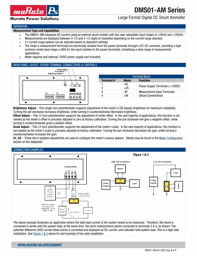
OPERATION Measurement Type and Capabilities
The DMS01-AM measures DC current using an external shunt resistor with two user-selectable input ranges of ±50mV and ±100mV. Measurements are displayed between 3-1/2 and 4-1/2 digits of resolution depending on the current range selected. 21 current range options can be selected based on dipswitch settings. The meter’s measurement terminals are electrically isolated from the power terminals through a DC-DC converter, providing a high
common-mode input range (±48V) for the input (relative to the power terminals), simplifying a wide range of measurement applications.
Meter requires and external 12VDC power supply (not included).
REAR PANEL LAYOUT, SCREW TERMINAL CONNECTIONS & CONTROLS
Terminal Block Terminal # Name Function 1 -VS
Power Supply Terminals (+12VDC) 2 +VS 3 -IN Measurement Input Terminals
(Shunt Connections) 4 +IN
Brightness Adjust – This single-turn potentiometer supports adjustment of the meter’s LED display brightness for maximum readability. Turning the pot clockwise increases brightness, while turning it counterclockwise decreases brightness. Offset Adjust – This 12-turn potentiometer supports the adjustment of meter offset. In the vast majority of applications, this function is not needed as the meter’s offset is precisely adjusted to zero at factory calibration. Turning the pot clockwise will give a negative offset, while turning it counterclockwise gives a positive offset. Scale Adjust – This 12-turn potentiometer supports the adjustment of the meter’s scale. In the vast majority of applications, this function is not needed as the meter’s scale is precisely adjusted at factory calibration. Turning the pot clockwise decreases the gain, while turning it counterclockwise increases the gain. S1, S2 – These two 6-position dipswitches are used to configure the meter’s various options. Details may be found in the Meter Configuration section of this datasheet.
CONNECTION EXAMPLES
The above example illustrates an application where the total load current of the system needs to be measured. Therefore, the shunt is connected in series with the system load, at the same time, the shunt measurement points connected to terminals 3 & 4, as shown. The potential difference (VDC) across these points is converted and displayed as DC current, and indicates total system load. This is a high-side installation. See Figure 1 & 2 above for and example of low-side installaiton.
Figure 1 & 2
DMS01-AM Series Large Format Digital DC Shunt Ammeter
DMS01-AM.A01.D06 Page 4 of 7
www.murata-ps.com/support
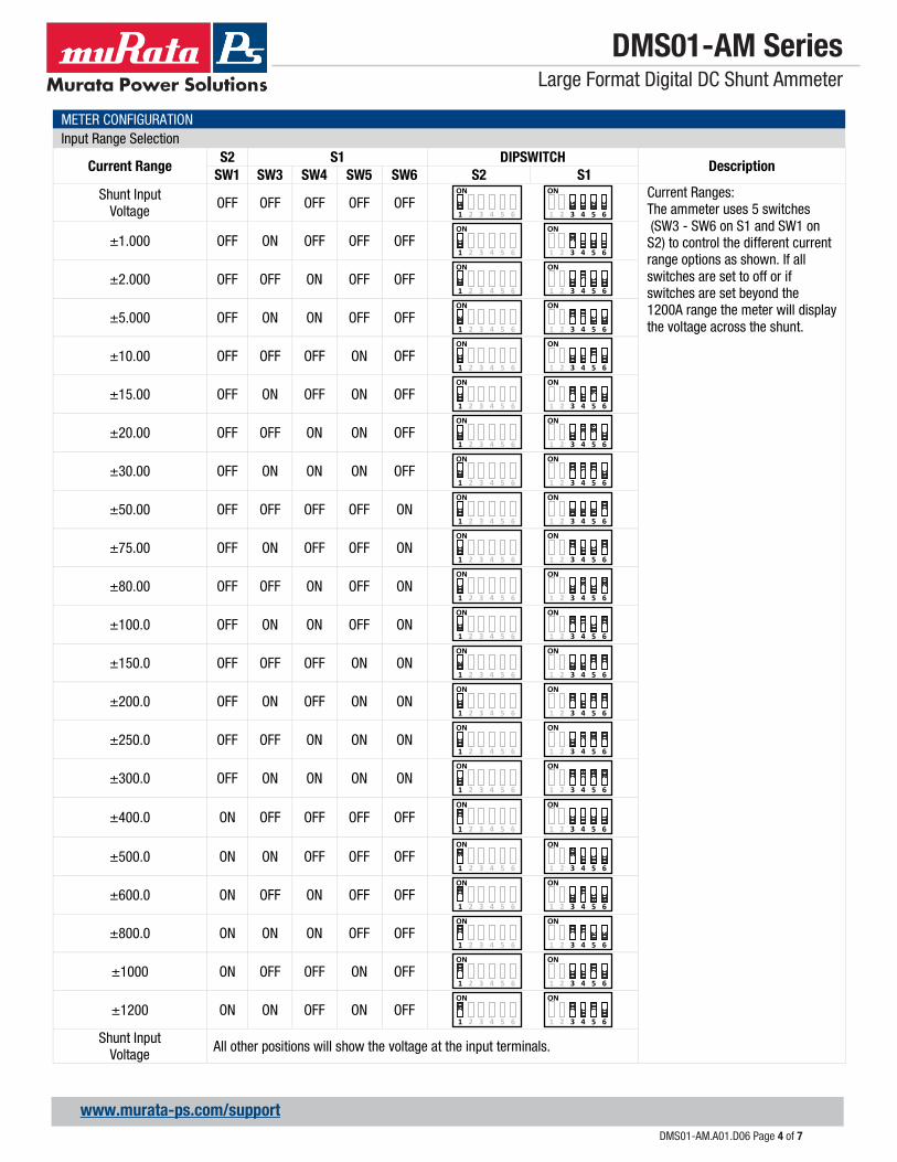
METER CONFIGURATION Input Range Selection
Current Range S2 S1 DIPSWITCH
Description SW1 SW3 SW4 SW5 SW6 S2 S1
Shunt Input Voltage OFF OFF OFF OFF OFF
Current Ranges: The ammeter uses 5 switches (SW3 - SW6 on S1 and SW1 on S2) to control the different current range options as shown. If all switches are set to off or if switches are set beyond the 1200A range the meter will display the voltage across the shunt.
±1.000 OFF ON OFF OFF OFF
±2.000 OFF OFF ON OFF OFF
±5.000 OFF ON ON OFF OFF
±10.00 OFF OFF OFF ON OFF
±15.00 OFF ON OFF ON OFF
±20.00 OFF OFF ON ON OFF
±30.00 OFF ON ON ON OFF
±50.00 OFF OFF OFF OFF ON
±75.00 OFF ON OFF OFF ON
±80.00 OFF OFF ON OFF ON
±100.0 OFF ON ON OFF ON
±150.0 OFF OFF OFF ON ON
±200.0 OFF ON OFF ON ON
±250.0 OFF OFF ON ON ON
±300.0 OFF ON ON ON ON
±400.0 ON OFF OFF OFF OFF
±500.0 ON ON OFF OFF OFF
±600.0 ON OFF ON OFF OFF
±800.0 ON ON ON OFF OFF
±1000 ON OFF OFF ON OFF
±1200 ON ON OFF ON OFF
Shunt Input Voltage All other positions will show the voltage at the input terminals.
ON
1 2 3 4 5 6
ON
1 2 3 4 5 6
ON
1 2 3 4 5 6
ON
1 2 3 4 5 6
ON
1 2 3 4 5 6
ON
1 2 3 4 5 6
ON
1 2 3 4 5 6
ON
1 2 3 4 5 6
ON
1 2 3 4 5 6
ON
1 2 3 4 5 6
ON
1 2 3 4 5 6
ON
1 2 3 4 5 6
ON
1 2 3 4 5 6
ON
1 2 3 4 5 6
ON
1 2 3 4 5 6
ON
1 2 3 4 5 6
ON
1 2 3 4 5 6
ON
1 2 3 4 5 6
ON
1 2 3 4 5 6
ON
1 2 3 4 5 6
ON
1 2 3 4 5 6
ON
1 2 3 4 5 6
ON
1 2 3 4 5 6
ON
1 2 3 4 5 6
ON
1 2 3 4 5 6
ON
1 2 3 4 5 6
ON
1 2 3 4 5 6
ON
1 2 3 4 5 6
ON
1 2 3 4 5 6
ON
1 2 3 4 5 6
ON
1 2 3 4 5 6
ON
1 2 3 4 5 6
ON
1 2 3 4 5 6
ON
1 2 3 4 5 6
ON
1 2 3 4 5 6
ON
1 2 3 4 5 6
ON
1 2 3 4 5 6
ON
1 2 3 4 5 6
ON
1 2 3 4 5 6
ON
1 2 3 4 5 6
ON
1 2 3 4 5 6
ON
1 2 3 4 5 6
ON
1 2 3 4 5 6
ON
1 2 3 4 5 6

DMS01-AM Series Large Format Digital DC Shunt Ammeter
DMS01-AM.A01.D06 Page 5 of 7
www.murata-ps.com/support
METER CONFIGURATION Current Range Selection
Input Range SW1 Dipswitch S1 Description
±50mV OFF ON
1 2 3 4 5 6
SW1 on S1 controls the meter’s input range. In the OFF position the input range is ±50mV, while in the ON position the meter’s range is ±100mV. ±100mV ON
ON
1 2 3 4 5 6
Current Range Selection Input Range SW1 Dipswitch S1 Description
±50mV OFF ON
1 2 3 4 5 6
SW1 on S1 controls the meter’s input range. In the OFF position the input range is ±50mV, while in the ON position the meter’s range is ±100mV. ±100mV ON
ON
1 2 3 4 5 6
Digital Filter On/Off Selection Digital Filter SW2 Dipswitch S1 Description
OFF OFF ON
1 2 3 4 5 6
SW2 on S1 controls the meter’s digital filter. In the OFF position, the filter is disabled and readings are updated at maximum speed. In the ON position, the filter is enabled, and readings are processed through a moving average filter, which results in more stable readings, but a slower response.
ON ON ON
1 2 3 4 5 6
Scale and Offset Trim Adjust Enable On/Off Trim Enable SW2 Dipswitch S2 Description
OFF OFF ON
1 2 3 4 5 6
The DMS01 ammeter provides two potentiometers for adjustment of the measurement scale and offset controls which can be enabled by SW2 on S2. When the switch is set to the OFF position the trim is disabled. When the switch is set to the ON position the trim is enabled.
ON ON ON
1 2 3 4 5 6

DMS01-AM Series Large Format Digital DC Shunt Ammeter
DMS01-AM.A01.D06 Page 6 of 7
www.murata-ps.com/support
TECHNICAL NOTES 1. Calibration The DMS01-AM is calibrated at the factory at the time of manufacture. When the Trim Enable switch (SW2 on S2) is turned off, the unit ignores the scale and offset potentiometer settings and reverts to factory calibration. When the Trim Enable switch is turned ON, the unit’s effective calibration may be changed by the user and may no longer be within datasheet specifications. 2. Protection and Fusing The DMS01-AM contains an internal PTC fuse as well as other protective elements that are intended for protection against brief electrical transients and misconnect conditions. Additional external protective components such as fuses and transient suppressors may be required depending on the application in which the meter is deployed. 3. Noisy Power Supplies In systems with noisy power supplies, connecting an external, non-polarized capacitor across the +VS and -VS inputs can help reduce measurement errors. In certain situations, the use of twisted pair or shield wiring may be required. 4. Installation IMPORTANT! To ensure safe and reliable operation, DMS01 meters must be installed and serviced by qualified technical personnel. Contact Murata Power Solutions if there is any doubt regarding their installation or operation. 5. Over-range Limit The meter will flash on and off when the input of the meter exceeds its minimum or maximum input voltage/current.
PANEL INSTALLATION PANEL CUTOUT
Notes: When mounting panel meter with hardware, a four hole pattern (four outermost holes) or the six hole pattern may be used at the customer’s option.

DMS01-AM Series Large Format Digital DC Shunt Ammeter
DMS01-AM.A01.D06 Page 7 of 7
www.murata-ps.com/support
MECHANICAL SPECIFICATIONS
Murata Power Solutions, Inc. 129 Flanders Rd. Westborough, Ma 01581, USA. ISO 9001 and 14001 REGISTERED
This product is subject to the following operating requirements and the Life and Safety Critical Application Sales Policy: Refer to: http://www.murata-ps.com/requirements/
Murata Power Solutions, Inc. makes no representation that the use of its products in the circuits described herein, or the use of other technical information contained herein, will not infringe upon existing or future patent rights. The descriptions contained herein do not imply the granting of licenses to make, use, or sell equipment constructed in accordance therewith. Specifications are subject to change without notice. ©2019 Murata Power Solutions, Inc..