large-eddy structures of turbulent swirling flows and methane-air swirling diffusion combustion
TRANSCRIPT

Acta Mech Sinica (2005) 21: 419–424DOI 10.1007/s10409-005-0065-3
RESEARCH PAPER
Liyuan Hu · Lixing Zhou · Jian Zhang
Large-eddy structures of turbulent swirling flows and methane-airswirling diffusion combustion∗
Received: 24 August 2004 / Accepted: 4 February 2005 / Revised: 20 February 2005 / Published online: 26 October 2005© Springer-Verlag 2005
Abstract Turbulent swirling flows and methane-air swirlingdiffusion combustion are studied by large-eddy simulation(LES) using a Smagorinsky-Lilly subgrid scale turbulencemodel and a second-order moment (SOM) SGS combus-tion model, and also by RANS modeling using the Rey-nolds Stress equation model with the IPCM+wall and IPCMpressure-strain models and SOM combustion model. TheLES statistical results for swirling flows give good agreementwith the experimental results, indicating that the adoptedsubgrid-scale turbulence model is suitable for swirling flows.The LES instantaneous results show the complex vortex shed-ding pattern in swirling flows. The initially formed largevortex structures soon break up in swirling flows. The LESstatistical results of combustion modeling are near the exper-imental results and are as good as the RANS-SOM modelingresults. The LES results show that the size and range of largevortex structures in swirling combustion are different fromthose of isothermal swirling flows, and the chemical reactionis intensified by the large-eddy vortex structures.
Keywords Swirling combustion · Swirling flows ·Large-eddy simulation
1 Introduction
The large-eddy simulation (LES) is becoming increasinglypopular in recent years for simulating turbulent flows andcombustion, because it can show the large-eddy structuresof turbulence and turbulent flame and give some physicalinsights for improving the RANS modeling. Pan et al. [1]simulated fully-developed rotating channel flows using the
∗The project supported by the Special Funds for Major State BasicResearch (G-1999-0222-07). The English text was polished by KerenWang.
Liyuan Hu · Lixing Zhou (B) · Jian ZhangDepartment of Engineering Mechanics, Tsinghua University, Beijing100084, ChinaE-mail: [email protected]
Smagorinsky model, and found that there is a lot of small-scale eddies. Their LES statistical results were not comparedwith the experimental results and the RANS simulation results.Liu et al. [2] studied the methane-air jet diffusion flameusing LES. A dynamic model was applied as the subgridscale model. The SGS term of reaction was simulated by adynamic similarity model. From the LES results, one can seethe large-eddy structures of turbulence and combustion, butthe LES statistical results were not compared with the exper-imental results or the RANS modeling results. Park et al. [3]studied turbulent premixed combustion behind a bluff bodyby LES using the Smagorinsky and the dynamic similaritysubgrid-scale turbulence models and the G-equation combus-tion model. The LES statistical results are in good agreementwith the measured time-averaged temperature and velocity,but the predicted RMS velocity is only in a qualitative agree-ment with the experimental results. Chakravarthy et al. [4]studied the bluff body stabilized flame by LES using the sub-grid kinetic energy turbulence model and the Linear-Eddycombustion model (LEM) and the G-equation combustionmodel. The LES statistical results are near the experimen-tal results. Kim et al. [5] simulated the turbulent premixedcombustion in a gas turbine combustor by LES using thesubgrid kinetic energy turbulence model and the G-equationflamelet model. The predicted time-averaged velocities agreewell with the experiments, but the statistical RMS veloci-ties and temperature are not validated by experiments. Thepredicted instantaneous flow field shows that the high swirlresults in a very complex vortex shedding pattern with sig-nificant azimuthal structures and the flame is located veryclose to the high shear region. So far, there are many studieson the LES of jet flows and jet combustion, but the LES ofswirling flows and turbulent swirling combustion are insuffi-ciently studied.
In this paper, the swirling flows measured in Ref. [6] arestudied using LES to find the features of turbulence structuresin swirling flows, and a methane-air turbulent swirling diffu-sion flame measured in Ref. [7] is studied using LES to givethe large-eddy structures of the flame. The LES statisticalresults of flow and combustion modeling are compared withthe experimental results and the RANS modeling results.

420 L.Y. Hu et al.
Table 1 The geometrical configuration and sizes of the swirl combustor
D1/mm D2/mm D3/mm Df /mm Dout/mm Lf /mm
Case 1 25 30.6 59 122 132 500Case 2 8 10 30 80 110 500
2 The SGS models and numerical procedure
The geometrical configuration and sizes of the swirl combus-tor are shown in Table 1 and Fig. 1. For case 1, the isothermalswirling flows in the combustor were measured by Roback[6]; the swirl number is 0.53; the air enters the combustorfrom the central inlet and the annular space; the inlet con-ditions are given by the mean velocities and six Reynoldsstress components measured in the cross section at a dis-tance of 5 mm from the inlet; the Reynolds number is 5 387.For case 2, the combustion in the swirl combustor was mea-sured by Chen [7]; the angle of the swirler in the annularspace is 30◦, corresponding to a swirl number of 0.43; the airand methane inlet flow rates are 8.9 m3/h and 0.893 2 m3/h,respectively.
In LES, the Smagorinsky-Lilly model is adopted for thesub-grid scale turbulence model and a second-order moment(SOM) sub-grid combustion model is proposed. The gov-erning equations employed for LES are obtained by filteringthe time-dependent Navier-Stokes equations in either Fourier(wave-number) space or configuration (physical) space. Thefiltered continuity, momentum, species and energy equationsare obtained as:
∂ρ
∂t+ ∂
∂xi(ρui) = 0, (1)
∂
∂t(ρui)+ ∂
∂xj(ρui uj ) = ∂
∂xj
(µ∂ui
∂xj
)
− ∂p
∂xi− ∂τij
∂xj, (2)
∂ρYs
∂t+ ∂
∂xj(ρuj Ys) = ∂
∂xj
( µSc
∂Ys
∂xj
)
−ws − wsgs − ∂gjsgs
∂xj, (3)
Fig. 1 Swirling combustor
∂ρh
∂t+ ∂
∂xj(ρhuj ) = ∂
∂xj
( µPr
∂h
∂xj
)− ∂qjsgs
∂xj, (4)
where ui is the velocity component, p is the pressure, µ isthe dynamic viscosity, h is the enthalpy, t is the time, thesubscripts i, j , k denote the space coordinates of xi , xj , xk ,respectively, i, j , k = 1, 2, 3. Sc is the Schmidt number,Sc = 0.7, Pr is the Prandtl number, Pr = 0.85. Ys is themass fraction of s species, and ws, wsgs are the filtered reac-tion rate and SGS reaction rate of s species, respectively. τijis the subgrid-scale stress defined by τij ≡ ρuiuj − ρui uj .The equations are closed by the Smagorinsky-Lilly model:
τij − 1
3τkkδij = −2µt Sij ,
Sij ≡ 1
2
(∂ui
∂xj+ ∂uj
∂xi
),
µt = ρL2s
∣∣S∣∣,∣∣S∣∣ ≡√
2Sij Sij ,
(5)
where µt is the subgrid-scale turbulent viscosity, ρ is thedensity and Ls is the mixing length for subgrid scales, Ls =min(κd, CsV
1/3), where Cs is the Smagorinsky constant,Cs = 0.1, κ is the von Karman constant, d is the distanceto the closest wall, and V is the volume of the computationalcell. The sub-grid scale mass flux and the sub-grid scale heatflux are modeled by
gjsgs = ρ(ujYs − uj Ys) = µt
σY
∂Ys
∂xj, (6)
qjsgs = ρ(ujT − uj T ) = µt
σT
∂T
∂xj. (7)
ws is the filtered reaction rate, σY = σT = 1.
ws = KY 1Y2,
K = Bρ2
∫exp(−E/RT )p(T )dT , (8)
p(T ) is the probability density function (PDF) of tempera-ture. T is the temperature,E is the activation energy,R is theuniversal gas constant. The subgrid-scale reaction rate is sim-ulated using a gradient modeling for the effect of small-scaletemperature and species fluctuations on the reaction rate
wsgs = ws
(Y ′
1Y′2
Y1Y2+ K ′Y ′
1
KY1+ K ′Y ′
2
KY2
),
φϕ = cµt
(∂
∂xj
)(∂
∂xj
)/ρ/∣∣S∣∣,
(9)

Large-eddy structures of turbulent swirling flows and methane-air swirling diffusion combustion 421
Fig. 2 Tangential velocity (s = 0.53)
where φ, ϕ, and denote the fluctuation and filtered val-ues of Y1 , Y2 and K , respectively, c and B are the modelconstants.
The grid sizes in x, y and z directions are 1 mm–2 mm.The number of grids is 839 595 for case 1 and 523 328 forcase 2. The mesh type is of hexagon. The time step is takenas 0.005 s, which is chosen based on the computation test.Within each time step the convergence can be reached after10 to 20 iterations. For the numerical procedure, the pressure-implicit with splitting of operators (PISO) algorithm is usedfor p-v corrections, the second order implicit differencescheme for the time-dependent term, and the central differ-ence scheme for the convection and diffusion terms areadopted. The stochastic component of the flow field at theinlet boundary is taken into account by superposing ran-dom perturbations on each velocity component, that is, ui =〈ui〉 + Iψ |u|, where I is the intensity of fluctuation, ψ is
a Gaussian random variable with ψ = 0 and√ψ ′ = 1.
The boundary condition at the exit is based on a fully devel-oped flow assumption where the gradients for all flow vari-
ables in the axial direction are zero, that is,∂ϕ
∂z= 0. At
the near-wall grid nodes the wall function approximation is
employed:u
uτ= 1
κlnE
uτy
ν, where κ is the von Karman
constant, κ = 0.418, E = 9.793. Running case 1 and case 2to make the flow field approaching a statistical steady statein a PC computer with a 2G EMS memory and double 2.8GCPU takes about 11 days and 20 days, respectively.
For case 1, the swirling flows are also simulated by RANSmodeling using the Reynolds Stress equation model withthe IPCM+wall and IPCM pressure-strain models [8]. TheQUICK difference scheme for the convection and diffusionterms are adopted, the finite difference equations are solved
using the SIMPLEC algorithm. The number of the two-dimensional grids is 14 766. Running a case in the same PCcomputer takes about half an hour.
For case 2, the swirling combustion is also simulated byRANS modeling using the SOM (second-order moment) tur-bulent combustion model described in Ref. [9].
The Arrhenius expression of laminar reaction kinetics formethane-air combustion is taken as:
wfu = 1.0 × 10¹⁰ρ2YoxYfu exp(−1.84 × 10⁴/T ). (10)
The SGS mass fluxes, heat fluxes, and SGS-SOMcombustion models are incorporated into the FLUENT 6.0code [10] by using the UDS function. For the RANS mod-eling of combustion, the QUICK difference scheme for theconvection and diffusion terms are adopted, the finite differ-ence equations are solved using the SIMPLEC algorithm andthe Reynolds stress turbulence model is adopted. The numberof the two-dimensional grids is 4 402. Running a case in thesame PC computer takes about an hour.
Both LES and RANS modeling are carried out on theplatform of FLUENT 6.0. The LES statistical results and theRANS simulation results are verified by experiments.
3 Results and discussion
Figures 2 and 3 show the comparison between LES statisticaltime-averaged velocities, RANS modeling results for swirl-ing flows with swirl number s = 0.53 (case 1) and therelated experimental results. Figure 2 shows the measuredand predicted tangential velocities. Both LES results andRANS modeling results using IPCM+Wall model are nearthe measurement results, but in some regions, LES resultsare better than RANS modeling results. Figure 3 shows the

422 L.Y. Hu et al.
Fig. 3 Axial velocity (s = 0.53)
Fig. 4 Instantaneous vorticity maps (s = 0.53, r-z plane, 90◦)
measured and predicted axial velocities. Good agreement isobtained between the LES results and experiments. The LESpredictions show the recirculation zone at the axis, the recov-ery of the axial velocity behind the recirculation zone anda small peak near the axis in the downstream region. Theresults obtained using the IPCM+Wall model also show therecirculation zone, but the length of the recirculation zoneis lager than that measured; the results obtained using theIPCM model show no recirculation zone and predictionsobtained using these two models show no peak near the axisin the downstream region. Therefore, the LES results are bet-ter than RANS modeling results; the adopted sub-grid-scaleturbulence model is suitable for swirling flows.
Figure 4 shows instantaneous vorticity maps in an r-zplane (θ = 90◦) for swirling flows with swirl number s =0.53 (case 1), when the flow field approaches a statisticallysteady state. It can be seen that the oncoming flow from thecentral and annular inlets forms a large shear layer betweenthe two recirculation zones, the swirl results in a very com-plex vortex-shedding pattern. The shear layer quickly breaksup into highly stretched vortex rings. As the vortices impact
on the wall, secondary vortices of the opposite sign are gener-ated. The vortex structures are seldom observed in the down-stream region except in the vicinity of the wall and axis.
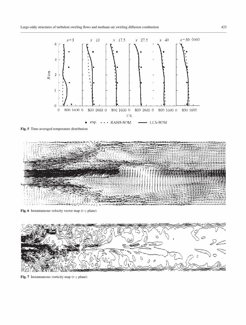
Figure 5 shows the comparison between the LES statisti-cally averaged temperature distribution and the experimentalresults and that obtained using the RANS-SOM model forswirling combustion (case 2). Both LES-SOM and RANS-SOM results are in good agreement with the experimentalresults, and the LES-SOM results are better at the cross sec-tions of x = 5 and x = 10. There are still some discrepancybetween the modeling results and the experiments near theinlet, which may be caused by using the simplified one-stepglobal kinetics.
Figures 6 and 7 show the instantaneous velocity vectorand vorticity map, respectively, during combustion in an r-zplane when the computation approaches a statistically steadystate for case 2. The oncoming flow from the central and annu-lar inlets forms a large shear layer. Many small vortices areformed around the shear layer. There is a recirculation zonewith a length of about the diameter of the combustion cham-ber. The shear layer diffuses quickly; the vorticity is largest
Large-eddy structures of turbulent swirling flows and methane-air swirling diffusion combustion 423
Fig. 5 Time-averaged temperature distribution
Fig. 6 Instantaneous velocity vector map (r-z plane)
Fig. 7 Instantaneous vorticity map (r-z plane)

424 L.Y. Hu et al.
Fig. 8 Instantaneous contour of temperature (r-z plane)
near the inlet and the large vortex structures formed in theupstream region are quickly broken up; the size and range oflarge vortex structures in swirling combustion are differentfrom those of isothermal swirling flows.
Figure 8 shows instantaneous contours of temperature inan r-z plane when the computation approaches a statisticallysteady state. The light color denotes high temperature andthe dark color denotes low temperature. Comparison betweenthe instantaneous temperature map and the vortex structuresshows that the flame is located very close to the region ofhighly coherent structures. Obviously, the chemical reactionis intensified by the large-eddy structures in swirling flows,but the flame structure is different from that in jet flows ornon-swirling separating flows.
4 Conclusions
(1) For swirling flows the LES statistical results are validatedby experiments. The Smogorinsky-Lilly’s SGS model issuitable for simulating swirling flows.
(2) Swirl results in a very complex vortex shedding pattern.The large vortices tend to break up quickly in swirlingflows.
(3) For swirling combustion, the LES SOM results are vali-dated by experiments.
(4) The large-eddy vortex structures intensify swirling diffu-sion combustion.
References
1. Pan, Y.K., Tanaka, T., Tsuji, Y.: Large-eddy simulation of particle-laden rotating channel flow. In: Proceedings of ASME FEDSM’00,Boston, CD-ROM, 2000
2. Liu, Y., Guo, Y.C., Zhang, H.Q., et al.: LES of methane-air planejet diffusion flame. J. Eng. Thermophys. 24(2), 343–346 (2003) (inChinese)
3. Park, N., Kobayashi, T., Taniguchi, N.: Application offlame-wrinkling LES combustion models to a turbulent premixedcombustion around bluff body. In: Proc. 3rd Inter. Symp. on Tur-bulence, Heat and Mass Transfer, Aichi Shuppan Press, 2000 pp.847–854
4. Chakravarthy, V.K., Menon, S.: Large eddy simulations of bluffbody stabilized flames. In: Proc. 3rd ASME/JSME Joint FluidsEngineering Conference, CD-ROM, San Fransisco, CA, 1999
5. Kim, W.W., Menon, S., Mongia, H.C.: Large-Eddy Simulation of aGas Turbine Combustor Flow. Combust. Sci. Tech. 143(25), 25–60(1999)
6. Roback, R., Johnson, B.V.: Mass and momentum turbulent trans-port experiments with confined swirling coaxial jets. Interim reportNASA-CR-168252, 1983
7. Zhou, L.X., Chen, X.L., Zhang, J.: Studies on the effect of swirl onNO formation in methane-air turbulent combustion. In: Proceed-ings of the Combustion Institute, Part 2, 29 (2003) pp. 2235–2242
8. Zhou, L.X.: Theory and Numerical Modeling of Turbulent Gas-Particle Flows and Combustion, Science Press, Beijing and CRCPress, Florida, 1993
9. Zhou, L.X., Qiao, L., Zhang, J.: A unified second-order momentturbulence-chemistry model for simulating turbulent combustionand NOx formation. Fuel 81, 1703–1709 (2002)
10. FLUENT 6.0 User’s Manual, FLUENT Inc. 2001