large-eddy simulation of underexpanded round jets...
TRANSCRIPT

Large-eddy simulation of underexpanded round jets
impinging on a flat plate 4 to 9 radii
downstream from the nozzle
Romain Gojon∗, Christophe Bogey† and Olivier Marsden‡
Laboratoire de Mecanique des Fluides et d’Acoustique
UMR CNRS 5506, Ecole Centrale de Lyon
69134 Ecully, France
Supersonic round jets have been computed by compressible Large Eddy Simulation(LES) using low-dispersion and low-dissipation schemes. The jets are underexpanded, andare characterized by a Nozzle Pressure Ratio of NPR = Pr/Pamb = 4.03, where Pr isthe stagnation pressure and Pamb is the ambient pressure. They have a fully expandedMach number of Mj = 1.56, an exit Mach number of Me = 1, and a Reynolds number ofRej = ujD/ν = 5× 10⁴, where ue and D are the jet exit velocity and the nozzle diameter,respectively. A free jet is first considered. Four jets impinging on a flat plate normallyare then examined. The distance L between the nozzle lip and the flat plate varies fromL = 4.16r0 up to L = 9.32r0 where r0 = D/2, for the impinging jets. The effects of theplate on the aerodynamic and acoustic properties of the jets are thus studied. For thefree jet, snapshots of density, pressure and vorticity are presented. Mean velocity fieldsare displayed, they are in good agreement with experimental data. The near pressurefield of the jet is investigated using Fourier decomposition. A screech tone component isfound, at a frequency comparing well with experimental data and theoretical models. Forthe four impinging jets, similarly, flow snapshots and mean flow fields are shown. Theresults obtained are similar to the corresponding measurements. The convection velocityof large-scale structures in the jet shear layers is then evaluated and an expression givingthe average convection velocity between the nozzle lips and the flat plate is proposed. Thenear pressure fields are then explored, and the main properties of the aeroacoustic feedbackmechanism occurring between the nozzle lip and the flat plate are presented. The resultsare consistent with theoretical models and experimental data.
I. Introduction
Very intense tones were observed experimentally by Powell1 and Wagner,2 among others, in the acousticfield of high subsonic and supersonic jets impinging on a flat plate normally. Moreover, as the distancebetween the nozzle and the flat plate varies, a staging phenomenon of the main tone frequency was obtained.Powell1 suggested that such tones are generated by a feedback mechanism between hydrodynamic instabilitiespropagating downstream from the nozzle to the plate and acoustic waves propagating upstream from theplate to the nozzle.
For round subsonic impinging jets, Ho & Nosseir3 and Nosseir & Ho4 built a model to predict the tonefrequencies of the feedback mechanism. This model is based on cross-correlations between microphones inthe near field of impinging jets. Later, Tam & Ahuja5 proposed that the upstream-propagating waves ofthe feedback mechanism correspond to neutral acoustic wave modes of the jets. They found an allowablefrequency range for each upstream propagating neutral acoustic wave mode of the jet flow using a vortex sheetjet model. They obtained results in line with the experimental data of Wagner2 for high subsonic round jets.Round supersonic jets impinging on a flat plate normally have been investigated experimentally by Henderson
∗PhD, [email protected].†CNRS Research Scientist, AIAA Senior Member & Associate Fellow, [email protected].‡[email protected].
1 of 18
American Institute of Aeronautics and Astronautics
Dow
nloa
ded
by C
hris
toph
e B
ogey
on
Aug
ust 2
4, 2
015
| http
://ar
c.ai
aa.o
rg |
DO
I: 1
0.25
14/6
.201
5-22
10
21st AIAA/CEAS Aeroacoustics Conference
22-26 June 2015, Dallas, TX
AIAA 2015-2210
Copyright © 2015 by R. Gojon, C. Bogey and O. Marsden. Published by the American Institute of Aeronautics and Astronautics, Inc., with permission.
AIAA Aviation

& Powell,6 Krothapalli et al.7 and Henderson et al.8 In some cases, a feedback mechanism is observed as insubsonic jets. This is very often the case when the jet is ideally expanded, but only for some nozzle-to-platedistances when the jet is imperfectly expanded. Henderson & Powell6 suggested that, in the latter case, thefeedback establishes only when a Mach disk forms upstream from the plate. Recirculation zones were alsoobserved near the flat plate by Krothapalli et al.7 More recently, for underexpanded impinging jets, Risbord& Soria9 explored the instability modes of the jets using ultra-high-speed Schlieren and shadowgraphytechniques. Axial and helical modes have been identified and the Mach disk located upstream from theplate has been observed to oscillate. For similar jets, Buchmann et al.10 observed the periodic formation oflarge-scale structures in the jet shear layers using a high spatial resolution Schlieren imaging. The completefeedback mechanism is visible, and includes large-scale structures in the shear layers propagating downstreamfrom the nozzle to the plate and acoustic waves propagating upstream from the plate to the nozzle. Finally,Mitchell et al.11 studied the periodic oscillation of the shear layer of underexpanded impinging jets usingtime-resolved Schlieren image sequences. Unfortunately, the connections between the different flow featureslisted above, namely, the shock-wave oscillations, the periodic shear-layer instabilities, the recirculation zonesnear the plate, and the production of tones, remain unclear. In order to understand these interactions, Kuo& Dowling12 considered that there is a flux resonance in the region of impact between the Mach disk andthe flat plate, and they developed a 1-D model of the Mach disk motion involving acoustic and entropywaves. With this model, a resonance condition is found, and for a given mean velocity flow, the frequencyof resonance of the Mach disk motion can be estimated. The predicted resonance frequencies matched theexperimental tone frequencies observed by Powell13 only for small plates, although the model was supposedto be adapted to all plate sizes. Moreover, the model is only valid when there is no recirculation zonesbetween the Mach disk and the plate. When the jet is strongly underexpanded and the plate is located inthe first cell of the free equivalent jet, a feedback loop involving disturbances in the shear layer between thesubsonic region downstream of the Mach disk and the supersonic peripheral flow was proposed by Hendersonet al.8 Numerical simulations were conducted by Dauptain et al.14, 15 for such configurations, and a modifiedmodel to predict the tone frequencies of the feedback loop was proposed.
In the present work, the LES of five round jets are carried out in order to investigate the feedbackmechanism occurring between the nozzle lip and the flat plate for impinging jets. In particular, the spectraland hydrodynamic properties of the jets are studied and compared with experimental data and theoreticalmodels. The paper is organized as follows. The jets parameters and the numerical methods used for theLES are given in section II. The aeroacoustic properties of the free jet is then presented in section III, andcompared with experimental data and theoretical models. The four jets impinging on a flat plate are thendescribed in section IV, and the feedback mechanism is studied by evaluating the convection velocity anddescribing the near pressure fields of the jets. Concluding remarks are given in section V.
II. Parameters
II.A. Jets parameters
Large-eddy simulations are performed for four jets impinging on a flat plate with nozzle-to-plate distancesL/r0 of 4.16, 5.6, 7.3 and 9.32, and for a free jet, as shown in table 1. The jets are referred to as JetL4,JetL5, JetL7 JetL9, and Jetfree, respectively. The ejection conditions of the jets and the nozzle-to-platedistances are similar to the conditions in the experiments of Henderson et al.8 The jets have a NozzlePressure Ratio of NPR = Pr/Pamb = 4.03, a fully expanded Mach number of Mj = 1.56, a Reynoldsnumber of Rej = ujD/ν = 5× 10⁴ and an exit Mach number of Me = 1. They originate from a pipe nozzlewhose lip thickness is equal to 0.1r0. At the nozzle exit, a Blasius boundary-layer mean velocity profile isimposed with a boundary-layer thickness of δBL = 0.15r0.
II.B. Numerical parameters
The unsteady compressible Navier-Stokes equations are solved on a cylindrical mesh (r, θ, z) by using anexplicit six-stage Runge-Kutta algorithm for time integration, and low-dispersion and low-dissipation expliciteleven-point finite differences for spatial derivation.16, 17 At the end of each time step, a relaxation filteringis applied to the flow variables in order to remove grid-to-grid oscillations and to dissipate subgrid-scaleturbulent energy.18, 19 The radiation conditions of Tam & Dong20 are implemented at the inflow and lateralboundaries of the computational domain. A sponge zone combining grid stretching and Laplacian filtering
2 of 18
American Institute of Aeronautics and Astronautics
Dow
nloa
ded
by C
hris
toph
e B
ogey
on
Aug
ust 2
4, 2
015
| http
://ar
c.ai
aa.o
rg |
DO
I: 1
0.25
14/6
.201
5-22
10

Mj Rej L/r0
JetL4 1.56 5× 10⁴ 4.16
JetL5 1.56 5× 10⁴ 5.6
JetL7 1.56 5× 10⁴ 7.3
JetL9 1.56 5× 10⁴ 9.32
Jetfree 1.56 5× 10⁴ -
Table 1. Jet parameters: fully expanded Mach number Mj , Reynolds number Rej , and nozzle-to-plate distance L/r0.
is also employed to damp the turbulent fluctuations before they reach the lateral boundaries. The presentsolver has been previously used21, 22 to simulate 3-D round jets at a Mach number Me = 0.9. Adiabaticconditions are imposed to the nozzle walls and to the flat plate. A shock-capturing filtering is applied in orderto avoid Gibbs oscillations near shocks. It consists in applying a conservative second-order filter optimised inFourier space at a magnitude determined each time step using a shock sensor.23 This method was successfullyused by de Cacqueray et al.24 for the LES of an overexpanded jet at Mach number Me = 3.3. Moreover,low-amplitude vortical disturbances, not correlated in the spanwise direction,21 are added in the boundarylayer in the nozzle, at around z = −r0 and r = 0.90r0, in order to generate velocity fluctuations at the nozzleexit. The strength α of the forcing is fixed to 0.02 to obtain turbulent intensities between 5% and 10% ofthe fully expanded jet velocity at the nozzle exit. This value is similar to those used in Bogey et al.21 Theaxis singularity is treated with the method proposed by Mohseni & Colonius.25 Notably, the first point closeto the axis is located at r = ∆r/2, where ∆r is the radial mesh size. Finally, a reduction of the effectiveresolution near the origin of the polar coordinates is implemented,26 in order to increase the admissible timestep of the simulation.
nr nθ nz number of points
JetL4 500 512 668 171× 106
JetL5 500 512 764 195× 106
JetL7 500 512 780 200× 106
JetL9 500 512 847 217× 106
Jetfree 500 512 1561 400× 106
Table 2. Mesh parameters: number of points in the radial, azimuthal and axial direction, and total number of points.
The simulations are carried out using an OpenMP-based in-house solver, and a total of 180, 000 iterationsare computed in each case for the steady state. The simulation time is thus equal to 1000r0/uj. Thecylindrical meshes (nr, nθ, nz) contain between 171 and 400 million points, as reported in table 2. Thevariations of the radial and axial mesh spacings are represented in figure 1.
0 5 10 15 180
0.02
0.04
0.06
0.08(a)
r/r0
∆r/
r 0
−2 0 2 4.16 5.6 7.3 9.320
0.02
0.04
0.06
0.08(b)
z/r0
∆z/
r 0
Figure 1. Representation of: (a) radial mesh spacings, and (b) axial mesh spacings: JetL4, . JetL5,JetL7, JetL9 and + + + Jetfree.
For the impinging jets, the minimal axial mesh spacing, near the nozzle lip and the flat plate, is equalto ∆z = 0.0075r0, and the maximal axial mesh spacing, between the nozzle and the plate, is equal to
3 of 18
American Institute of Aeronautics and Astronautics
Dow
nloa
ded
by C
hris
toph
e B
ogey
on
Aug
ust 2
4, 2
015
| http
://ar
c.ai
aa.o
rg |
DO
I: 1
0.25
14/6
.201
5-22
10

∆z = 0.015r0 for JetL4 and JetL5, and to ∆z = 0.03r0 for JetL7 and JetL9. The minimal radial spacingis ∆r = 0.0075r0 at r = r0, and the maximal radial spacing is ∆r = 0.06r0 for 5r0 ≤ r ≤ 15r0. Then,for r ≥ 15r0, a sponge zone is implemented. For the free jet, the grid is the same in the radial direction,but differs in the axial direction far from the nozzle with a maximal axial mesh spacing of ∆z = 0.03r0 for5r0 ≤ z ≤ 30r0, and a sponge zone for z ≥ 30r0. These discretizations allow acoustic waves with Strouhalnumbers up to StD = fD/ue = 6.4 to be well propagated, where f is the frequency. Finally, note that gridsare stretched at rates lower than 1% outside the sponge zones, in order to preserve numerical accuracy.
III. Results for the free jet
The results obtained for the free jet are first described for validation of the numerical set-up and forcomparison with the results for the impinging jets.
III.A. Flow snapshots
In order to illustrate the shear-layer development downstream of the nozzle, a snapshot of the vorticitynorm obtained in the plane (z, r) is presented in figure 2. The shear layer develops rapidly downstream ofthe nozzle exit with both small and large turbulent structures, in agreement with the Reynolds number ofRej = 5× 10⁴. The end of the jet potential core appears to be located around 17.5r0. Lau et al.27 proposedan empirical model for the length of the potential core zp for isothermal jets with Mach number up to 2.5,which writes
zpDj
= 4.2 + 1.1M2j (1)
where Dj and Mj are the fully expanded diameter and the Mach number of the jet.For the present free jet, the parameters Mj = 1.56 and Dj = 2.2mm give a potential core length of
zp = 15r0. Tam et al.28 included in the expression (1) the temperature ratio between the stagnation and theambient temperatures in order to take into account compressibility effects. This expression gives zp = 17.5r0.A good overall agreement is thus found between the present result and the empirical expression derived byTam et al.28
Figure 2. Snapshot in the (z, r) plane of the vorticity norm |ω| for Jetfree. The colour scale ranges up to the level of10ue/D.
In order to visualize both the flow and acoustic fields, a snapshot in the (z, r) plane of the density andthe fluctuating pressure is provided in figure 3(a). A shock-cell structure, typical of an underexpanded jet,is obtained with around ten shock cells visible. Because the jet is highly underexpanded, a Mach disk isfound in the first cell, at z = 2.35r0 and shear layers can be observed in figure 2 between the subsonicand the supersonic region downstream of the Mach disk. This is in agreement with the results of Powell,13
Henderson,29 and Addy,30 who noted that a Mach disk is generated in underexpanded jets for NPR > 3.8or 3.9. In the pressure field, acoustic waves and two acoustic contributions can be seen. First, circularwavefronts are visible and seem to originate from the first five cells. They are due to the interactionsbetween the shocks and the turbulence in the jet shear layers. Upstream propagating acoustic waves canalso be observed on each side of the jet, in the vicinity of the nozzle. For the comparison, a Schlieren pictureof an underexpanded jet obtained by Andre et al.31 is displayed in figure 3(b). The fully expanded Machnumber of the jet is Mj = 1.55 and the exit Mach number is Me = 1. A great similarity is noted with
4 of 18
American Institute of Aeronautics and Astronautics
Dow
nloa
ded
by C
hris
toph
e B
ogey
on
Aug
ust 2
4, 2
015
| http
://ar
c.ai
aa.o
rg |
DO
I: 1
0.25
14/6
.201
5-22
10

the computed jet. In particular, the Mach disk is clearly visible in the first cell as well as the shear layersdownstream.
Figure 3. (a) Snapshot in the (z, r) plane of the density in the jet and close to the flat plate, and of the fluctuating
pressure for Jetfree. The colour scale ranges from 1 to 3 kg.m−3 for the density and from −2000 to 2000 Pa for thepressure; (b) Schlieren picture of an underexpanded jet obtained by Andre et al.
31 for a Mj = 1.55 and Me = 1 jet.
III.B. Mean fields
The mean axial and radial velocity fields are presented in figure 4, where the experimental PIV results ofAndre et al.31 are also displayed. The geometry of the shock-cell structure and the levels obtained in theLES and in the experiment are in good agreement.
Figure 4. Mean fields in the (z, r) plane of (a) axial and (b) radial velocities for Jetfree. The colour scale ranges from
0 to 600 m.s−1 for the axial velocity and from −150 to 150 m.s−1 for the radial velocity; the PIV results of Andre et
al.31 for a Mj = 1.55 and Me = 1 jet are displayed in the black rectangles.
In figure 4(a), the length of the first shock cell Ls of the jet appears to be 3.20r0. This result is identicalto those of Henderson et al.8 for a similar free jet. Besides, the length of the first cell can be estimated byusing a first-order shock solution based on the pressure ratio ps/pa, where ps is the pressure perturbationof the shock-cell structure and ps + pa is the actual pressure in the jet. This solution was first proposed byPrandtl32 in 1904. Later, the following approximated solution was given by Tam & Tanna:33
Ls =πDjβ
µ1
≃ 1.306βDj (2)
5 of 18
American Institute of Aeronautics and Astronautics
Dow
nloa
ded
by C
hris
toph
e B
ogey
on
Aug
ust 2
4, 2
015
| http
://ar
c.ai
aa.o
rg |
DO
I: 1
0.25
14/6
.201
5-22
10
where µ1 is the first zero of the zero-order Bessel functions of the first kind and β =√
M2j − 1. This
expression is called Prandt formula. Expression (2), for the present jet, provides Ls = 3.45r0, which isslightly larger than the measured and computed values. Later, the expression (2) was improved by Pack34
by calculating the first forty coefficients of the model of Prandtl,32 yielding Ls = 1.22βDj, hence Ls = 3.20r0for the present jet, which is similar to the values reported above.
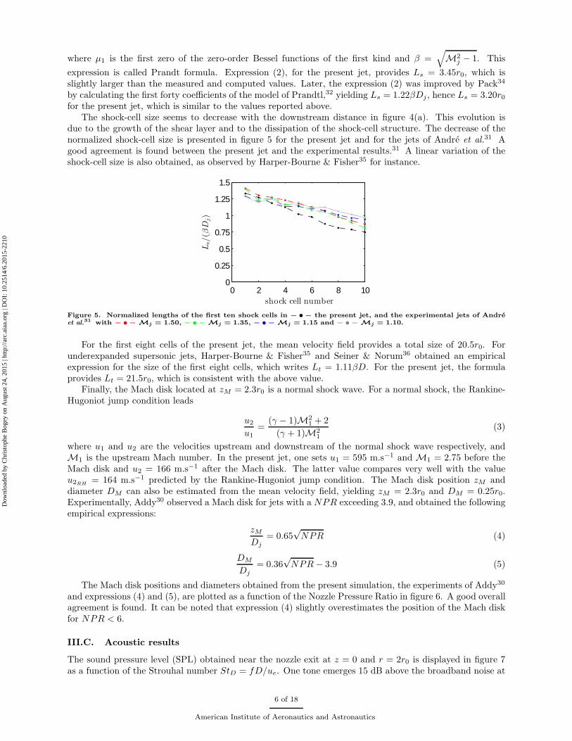
The shock-cell size seems to decrease with the downstream distance in figure 4(a). This evolution isdue to the growth of the shear layer and to the dissipation of the shock-cell structure. The decrease of thenormalized shock-cell size is presented in figure 5 for the present jet and for the jets of Andre et al.31 Agood agreement is found between the present jet and the experimental results.31 A linear variation of theshock-cell size is also obtained, as observed by Harper-Bourne & Fisher35 for instance.
0 2 4 6 8 100
0.25
0.5
0.75
1
1.25
1.5
shock cell number
Ls/(β
Dj)
Figure 5. Normalized lengths of the first ten shock cells in − • − the present jet, and the experimental jets of Andreet al.
31 with − • − Mj = 1.50, − • − Mj = 1.35, − • − Mj = 1.15 and − • − Mj = 1.10.
For the first eight cells of the present jet, the mean velocity field provides a total size of 20.5r0. Forunderexpanded supersonic jets, Harper-Bourne & Fisher35 and Seiner & Norum36 obtained an empiricalexpression for the size of the first eight cells, which writes Lt = 1.11βD. For the present jet, the formulaprovides Lt = 21.5r0, which is consistent with the above value.
Finally, the Mach disk located at zM = 2.3r0 is a normal shock wave. For a normal shock, the Rankine-Hugoniot jump condition leads
u2
u1
=(γ − 1)M2
1 + 2
(γ + 1)M21
(3)
where u1 and u2 are the velocities upstream and downstream of the normal shock wave respectively, andM1 is the upstream Mach number. In the present jet, one sets u1 = 595 m.s−1 and M1 = 2.75 before theMach disk and u2 = 166 m.s−1 after the Mach disk. The latter value compares very well with the valueu2RH
= 164 m.s−1 predicted by the Rankine-Hugoniot jump condition. The Mach disk position zM anddiameter DM can also be estimated from the mean velocity field, yielding zM = 2.3r0 and DM = 0.25r0.Experimentally, Addy30 observed a Mach disk for jets with a NPR exceeding 3.9, and obtained the followingempirical expressions:
zMDj
= 0.65√NPR (4)
DM
Dj
= 0.36√NPR− 3.9 (5)
The Mach disk positions and diameters obtained from the present simulation, the experiments of Addy30
and expressions (4) and (5), are plotted as a function of the Nozzle Pressure Ratio in figure 6. A good overallagreement is found. It can be noted that expression (4) slightly overestimates the position of the Mach diskfor NPR < 6.
III.C. Acoustic results
The sound pressure level (SPL) obtained near the nozzle exit at z = 0 and r = 2r0 is displayed in figure 7as a function of the Strouhal number StD = fD/ue. One tone emerges 15 dB above the broadband noise at
6 of 18
American Institute of Aeronautics and Astronautics
Dow
nloa
ded
by C
hris
toph
e B
ogey
on
Aug
ust 2
4, 2
015
| http
://ar
c.ai
aa.o
rg |
DO
I: 1
0.25
14/6
.201
5-22
10

2 4 6 8 100
0.5
1
1.5
2
NPR
z M/D
j
(a)
2 4 6 8 100
0.2
0.4
0.6
0.8
NPR
DM/D
j
(b)
Figure 6. (a) Position and (d) diameter of the Mach disk at the end of the first shock cell obtained: • for Jetfree, ×in the experiment of Addy30 and using expressions (4) and (5).
a Strouhal number of StD = 0.38. Such a result is typical of a screeching jet, see for instance in Westley &Woolley,37 Tam & Tanna,33 Panda,38 and Andre et al.31 The tone at StD = 0.38 can therefore be attributedto the generation of screech noise by the jet.
0 0.5 1 1.5 2 2.5120
130
140
150
160
StD = fD/ue
SPL(dB/St)
Figure 7. Sound pressure level (SPL) at r = 2r0 and z = 0 as a function of the Strouhal number for Jetfree.
The near pressure fields in the (z, r) plane have been recorded every 50th time step. The results arearranged in the M ×N matrix:
Pall =
P 11 P 2
1 . PN1
P 12 P 2
2 . PN2
. . . .
P 1M P 2
M . PNM
(6)
where N is the number of samplings, and M = nz × 2nr is the total number of points in a (z, r) plane. Thepressure field obtained at a given time is thus provided by one column of Pall. A Fast Fourier Transform isapplied to each row of the matrix Pall. In this way, for a given frequency, the amplitude and the phase fieldscan be displayed. For the tone at StD = 0.38, they are given in figure 8. The amplitude field in figure 8(a)exhibits a cell structure different from the shock-cell structure. Such a structure is observed in the presenceof an hydrodynamic-acoustic standing wave, as is the case in supersonic screeching jets, see in Panda.38 Thetypical cell length in this structure is equal to the wavelength Lsw of the standing wave formed between thedownstream propagating large-scale structures in the shear layers and the upstream propagating acousticwaves. The screech frequency fs associated with this wavelength is provided by the model of Panda:38
fs =uc
Lsw(1 + uc/c0)(7)
where uc is the mean convection velocity of the structures in the shear layers and c0 is the ambient soundspeed. For the present jet, the cell structure in figure 8(a) shows a spatial periodicity of Lsw ≃ 2.5r0. The
7 of 18
American Institute of Aeronautics and Astronautics
Dow
nloa
ded
by C
hris
toph
e B
ogey
on
Aug
ust 2
4, 2
015
| http
://ar
c.ai
aa.o
rg |
DO
I: 1
0.25
14/6
.201
5-22
10

mean convection velocity, computed from cross-correlations of axial velocity fluctuations in the shear layers,see in section IV, is uc = 0.65uj, where uj is the fully expanded jet velocity. Expression (7) thus leads to ascreech Strouhal number of StD = fsD/ue ≃ 0.38, which is in agreement with the tone frequency of figure 7.
Figure 8. Amplitude (a) and phase (b) fields in the (z, r) plane obtained for the dominant tone frequency of Jetfree atStD = 0.38.
In figure 8(b), a 180 degree phase shift with respect to the jet axis is visible. This indicates that the modeat StD = 0.38 is sinuous or helical. More precisely, using a Fourier decomposition of the fluctuating pressureon 32 sensors regularly-spaced in the azimuthal direction, at z = 0 and r = 2r0, it turns out to be helical.This mode is compared in figure 9 with the dominant screech tones found in the experiments of Powell etal.39 for round supersonic underexpanded jets. These tones are associated with varicose modes (A1 andA2), with sinuous and sometimes helical modes (B), with helical modes (C), and with sinuous modes (D).The screech tone in the present jet falls in the vicinity of tones C, in agreement with the results reportedabove. Consequently, both the frequency and the nature of the screech mode in Jetfree are consistent withthe theoretical predictions of Panda38 and the measurements of Powell et al.39
1 1.2 1.4 1.6 1.8 20
0.2
0.4
0.6
0.8
M j
St D
A1
A2
BC
D
Figure 9. • Dominant screech tone frequencies obtained in the experiments of Powell et al.39 as a function of the fully
expanded Mach number Mj ; × dominant screech tone frequency in Jetfree.
In the next section, jets with the same exit conditions as Jetfree impinging normally on a flat plate forfour different nozzle-to-plate distances are presented. The positions of the plate with respect to the shock-cellstructure of Jetfree are shown in figure 10. For JetL4, with L = 4.16r0, the plate is located in the first half ofthe second cell of the shock-cell structure, where the velocity increases and the pressure decreases with theaxial distance on the jet centerline, whereas for JetL5, with L = 5.6r0, it lies in the second half of the secondcell, where velocity decreases and pressure increases. For JetL7 and JetL9, with L = 7.3r0 and L = 9.32r0,the plates are located in the first halves of the third and of the fourth cells of the shock-cell structure,
8 of 18
American Institute of Aeronautics and Astronautics
Dow
nloa
ded
by C
hris
toph
e B
ogey
on
Aug
ust 2
4, 2
015
| http
://ar
c.ai
aa.o
rg |
DO
I: 1
0.25
14/6
.201
5-22
10

respectively. These remarks are of interest, given that, according to Henderson et al.,8 the occurrence ofintense tones in imperfectly expanded impinging jets depends on the location of the plate in the shock-cellstructure of the corresponding free jet.
Figure 10. Mean density field in the (z, r) plane for Jetfree. The colour scale ranges from 1 to 3 kg.m−3. The blacklines correspond to the position of the plates for the impinging jets.
IV. Results for the impinging jets
IV.A. Flow snapshots
In order to illustrate the flow fields in the impinging jets, isosurfaces of density are displayed in figure 11for JetL9. In the jet, a shock-cell structure appears clearly between the nozzle and the plate in blue an red.The boundaries of the mixing layers are also well visible in cyan. In addition, longitudinal structures can beseen on the outer border of the first shock cell. They have been described in different experiments, includingthose by Arnette et al.40 They are due to small perturbations at the nozzle exit, which are amplified byTaylor-Goertler-type instabilities, and are specific to underexpanded jets.
Figure 11. Isosurfaces of density for JetL9. The blue, cyan and red isosurfaces correspond to the values of 0.8, 1.25
and 2.5 kg.m−3, respectively. The nozzle and the flat plate are represented in grey.
9 of 18
American Institute of Aeronautics and Astronautics
Dow
nloa
ded
by C
hris
toph
e B
ogey
on
Aug
ust 2
4, 2
015
| http
://ar
c.ai
aa.o
rg |
DO
I: 1
0.25
14/6
.201
5-22
10

Snapshots of the vorticity norm obtained in the (z, r) plane for JetL4, JetL5, JetL7 and JetL9, arepresented in figure 12. In JetL4, in figure 12(a), large vortical structures of typical size 0.2r0 are found inthe shear layers. They are strongly correlated in the azimuthal direction (not shown here). The distancebetween the two sliplines visible downstream of the Mach disk at z ≃ 2r0, equal to 0.5r0, is larger than thatin the free jet, equal to 0.23r0, which results from a larger diameter of the Mach disk. In JetL5, JetL7 andJetL9, the shear layers develop in the same way as in Jetfree with both small and large turbulent structures.The distance between the sliplines downstream of the Mach disk is also the same as in Jetfree.
Figure 12. Snapshots in the (z, r) plane of the vorticity norm |ω| for for (a) JetL4, (b) JetL5, (c) JetL7 and (d) JetL9.The colour scale ranges up to the level of 10ue/D.
Snapshots of density and fluctuating pressure in the (z, r) plane are provided in figure 13 for the fourjets. In figure 13(a), for JetL4, one shock cell appears in the density field. Compared to the free jet wherethe Mach disk is located at zM = 2.3r0, the cell here is shorter, with zM = 1.85r0. The Mach disk is alsothicker than in the free jet. An annular oblique shock is visible around the Mach disk, as in Jetfree. Thetemporal evolution of the jet shows a strong axial motion of the Mach disk, as experimentally observed byRisborg & Soria.9 Moreover, the periodic motion of the Mach disk is synchronized with the strong sphericalsound waves visible in the pressure field. In figure 13(b), for JetL5, the first cell of the shock-cell structure issimilar to that in Jetfree. A Mach disk forms upstream from the plate, at z = 4.25r0, in the second cell. Inthe pressure field, sound waves seem to propagate from the region of the impact. In figure 13(c), for JetL7,the two first cells of the shock-cell structure resemble those in Jetfree. Two acoustic contributions are visiblein the pressure field. First, wavefronts centered around the annular oblique shock of the first cell appear.They are due to the interactions between the oblique shock and the turbulence in the shear layers. A secondacoustic contribution seems to come from the region of impact. Finally, in figure 13(d), for JetL9, a Machdisk forms upstream from the plate at z = 7.7r0, in the third cell. The pressure field looks like the pressurefield of JetL7.
IV.B. Mean flows
The mean velocity fields obtained in the (r, z) plane are presented in figure 14. A good agreement is foundwith the measurements of Henderson et al.8 For JetL5 and JetL7, however, shock cells are slightly shorterin the simulation than in the experiment. For JetL4, in figure 14(a), the effects of the flat plate on thefirst shock cell mentioned previously are clearly visible. For JetL5 and JetL9, a second cell and a third cell,respectively, cannot fully form before the plate, and a Mach disk is generated close to the wall. On thecontrary, for JetL7, in figure 14(c), the two first cells of the shock-cell structure appear to spread over theentire space between the nozzle and the plate, and no Mach disk is created upstream from the plate. Finally,for JetL4, JetL5 and JetL9, recirculation zones are found on each side of the jet near the plate, in agreementwith the experiments of Henderson & Powell,6 Krothapalli et al.7 and Henderson et al.8 These results arealso in line with the observations of Kuo & Dowling12 who noted the appearance of a recirculation zonewhen the distance between the Mach disk and the flat plate exceeds 1.2r0. This distance is indeed equal to2.3r0, 1.35r0 and 1.6r0 for JetL4, JetL5 and JetL9.
10 of 18
American Institute of Aeronautics and Astronautics
Dow
nloa
ded
by C
hris
toph
e B
ogey
on
Aug
ust 2
4, 2
015
| http
://ar
c.ai
aa.o
rg |
DO
I: 1
0.25
14/6
.201
5-22
10

Figure 13. Snapshots in the (z, r) plane of the density in the jet and close to the flat plate, and of the fluctuating
pressure for (a) JetL4, (b) JetL5, (c) JetL7 and (d) JetL9. The colour scale ranges from 1 to 3 kg.m−3 for the densityand from −2000 to 2000 Pa for the pressure.
11 of 18
American Institute of Aeronautics and Astronautics
Dow
nloa
ded
by C
hris
toph
e B
ogey
on
Aug
ust 2
4, 2
015
| http
://ar
c.ai
aa.o
rg |
DO
I: 1
0.25
14/6
.201
5-22
10

Figure 14. Mean velocity fields in the (z, r) plane for (a) JetL4, (b) JetL5, (c) JetL7 and (d) JetL9. The colour scale
ranges from 0 to 500 m.s−1. The experimental results of Henderson et al.8 are represented in the black rectangles.
IV.C. Convection velocity
The convection velocity uc of the large-scale structures in the jet shear layers has been estimated. It hasbeen calculated at the center of the shear layer, whose position is given by the maximum of the root meansquare of velocity fluctuations. The resulting path for JetL9 is for example displayed in figure 15. Alongthis path, axial velocity cross-correlations are computed to obtain the convection velocity. The results areshown in figure 16(a) for the free jet and the impinging jets.
Figure 15. Root mean square values of velocity fluctuations for JetL9. The color scale ranges from 0 to 100 m.s−1.The black line shows the position of the maximum values.
0 2 4.16 5.6 7.3 9.320
0.2
0.4
0.6
0.8
z/r0
uc/uj
(a)
2 4.16 5.6 7.3 9.320.45
0.5
0.55
0.6
0.65
L/r0
<uc>
/uj
(b)
Figure 16. (a) Convection velocity of the large scale structures in the shear layers for JetL4, . JetL5,JetL7, JetL9 and + + + Jetfree. The dashed vertical grey lines correspond to the end of the cells in
the shock-cell structure of the free jet. (b) Mean convection velocity between the nozzle and the plate for: × the fourimpinging jets and the expression 8.
The convection velocity in the shear layers is not constant but varies according to the shock-cell structure.In the first cell, the convection velocity increases between the nozzle lips and the position of the Mach disk,as the velocity inside the jet grows, and then decreases down to the end of the cell, following the velocityreduction in the jet downstream of a Mach disk or an oblique shock. Similar variations can be seen for allcells. They are consistent with the experimental results obtained by Westley & Woolley37 and by Andre
12 of 18
American Institute of Aeronautics and Astronautics
Dow
nloa
ded
by C
hris
toph
e B
ogey
on
Aug
ust 2
4, 2
015
| http
://ar
c.ai
aa.o
rg |
DO
I: 1
0.25
14/6
.201
5-22
10

et al.31 for imperfectly expanded round jets. The modification of the first shock cell in JetL4 describedearlier is also visible in figure 16, with a maximum of the convection velocity reached around zM = 1.85r0for JetL4 but around zM = 2.3r0 for the other jets. Moreover, for Jetfree, the convection velocity tends toa value around uc = 0.65uj in the downstream direction, which is in good agreement with the experimentalobservations of Harper-Bourne & Fisher,35 who found uc = 0.70uj using a crossed-beam Schlieren technique.
Given the variations of the convection velocity in figure 16, it does not appear relevant to use the sameconvection velocity between the lip and the plate for all nozzle-to-plate distances, as was the case in themodel of Ho & Nosseir3 and Nosseir & Ho4 to predict the frequencies of the feedback mechanism. Indeed,the average convection velocity between the nozzle and the flat plate for the four impinging jets, displayedin figure 16(b), varies from 0.54uj for JetL4 up to 0.59uj for JetL9. It can be approximated by the averageconvection velocity
< uc > (L) = 0.65uj − (0.65uj − 0.5ue)1
1 + L/Dj
(8)
which is represented in figure figure 16(b) for a nozzle-to-plate distance ranging from L = 2r0 to L = 10r0.Expression (8) tends to 0.65uj for large distances L, in agreement with the result of Jetfree, and tends to0.5ue near the nozzle, as expected.
IV.D. Pressure spectra
The sound pressure levels obtained at r = 2r0 and z = 0 are plotted in figure 17 as a function of the Strouhalnumbers StD = fD/ue. The Strouhal number of the tones whose levels are 5 dB higher than the broadbandnoise are given in table 3.
0 0.5 1 1.5 2 2.5120
140
160
180(a)
St = fD/ue
SPL(dB/St)
0 0.5 1 1.5 2 2.5120
140
160
180(b)
St = fD/ue
SPL(dB/St)
0 0.5 1 1.5 2 2.5120
140
160
180(c)
St = fD/ue
SPL(dB/St)
0 0.5 1 1.5 2 2.5120
140
160
180(d)
St = fD/ue
SPL(dB/St)
Figure 17. Sound pressure levels (SPL) at r = 2r0 and z = 0 as a function of the Strouhal number for (a) JetL4,(b) JetL5, (c) JetL7 and (d) JetL9.
13 of 18
American Institute of Aeronautics and Astronautics
Dow
nloa
ded
by C
hris
toph
e B
ogey
on
Aug
ust 2
4, 2
015
| http
://ar
c.ai
aa.o
rg |
DO
I: 1
0.25
14/6
.201
5-22
10
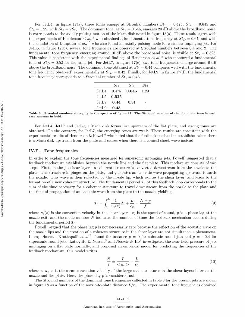
For JetL4, in figure 17(a), three tones emerge at Strouhal numbers St1 = 0.475, St2 = 0.645 andSt3 = 1.29, with St3 = 2St2. The dominant tone, at St2 = 0.645, emerges 20 dB above the broadband noise.It corresponds to the axially pulsing motion of the Mach disk noted in figure 13(a). These results agree withthe experiments of Henderson et al.,8 who obtained a fundamental tone frequency at StD = 0.67, and withthe simulation of Dauptain et al.,15 who also found an axially pulsing mode for a similar impinging jet. ForJetL5, in figure 17(b), several tone frequencies are observed at Strouhal numbers between 0.4 and 2. Thefundamental tone frequency, emerging around 10 dB above the broadband noise, is visible at St2 = 0.525.This value is consistent with the experimental findings of Henderson et al.,8 who measured a fundamentaltone at StD = 0.52 for the same jet. For JetL7, in figure 17(c), two tone frequencies emerge around 6 dBabove the broadband noise. The dominant tone obtained at St1 = 0.44 compares well with the fundamentaltone frequency observed8 experimentally at StD = 0.42. Finally, for JetL9, in figure 17(d), the fundamentaltone frequency corresponds to a Strouhal number of St1 = 0.43.
St1 St2 St3
JetL4 0.475 0.645 1.29
JetL5 0.525 - -
JetL7 0.44 0.54 -
JetL9 0.43 - -
Table 3. Strouhal numbers emerging in the spectra of figure 17. The Strouhal number of the dominant tone in eachcase appears in bold.
For JetL4, JetL7 and JetL9, a Mach disk forms just upstream of the flat plate, and strong tones areobtained. On the contrary, for JetL7, the emerging tones are weak. These results are consistent with theexperimental results of Henderson & Powell6 who noted that the feedback mechanism establishes when thereis a Mach disk upstream from the plate and ceases when there is a conical shock wave instead.
IV.E. Tone frequencies
In order to explain the tone frequencies measured for supersonic impinging jets, Powell1 suggested that afeedback mechanism establishes between the nozzle lips and the flat plate. This mechanism consists of twosteps. First, in the jet shear layers, a coherent structure is convected downstream from the nozzle to theplate. The structure impinges on the plate, and generates an acoustic wave propagating upstream towardsthe nozzle. This wave is then reflected by the nozzle lip, which excites the shear layer, and leads to theformation of a new coherent structure. The fundamental period T0 of this feedback loop corresponds to thesum of the time necessary for a coherent structure to travel downstream from the nozzle to the plate andthe time of propagation of an acoustic wave from the plate to the nozzle, yielding
T0 =
∫ L
0
1
uc(z)dz +
L
c0=
N + p
f(9)
where uc(z) is the convection velocity in the shear layers, c0 is the speed of sound, p is a phase lag at thenozzle exit, and the mode number N indicates the number of time the feedback mechanism occurs duringthe fundamental period T0.
Powell1 argued that the phase lag p is not necessarily zero because the reflection of the acoustic wave onthe nozzle lips and the creation of a coherent structure in the shear layer are not simultaneous phenomena.In experiments, Krothapalli et al.7 found for instance p = 0 for subsonic round jets and p = −0.4 forsupersonic round jets. Later, Ho & Nosseir3 and Nosseir & Ho4 investigated the near field pressure of jetsimpinging on a flat plate normally, and proposed an empirical model for predicting the frequencies of thefeedback mechanism, this model writes
N
f=
L
< uc >+
L
c0(10)
where < uc > is the mean convection velocity of the large-scale structures in the shear layers between thenozzle and the plate. Here, the phase lag p is considered null.
The Strouhal numbers of the dominant tone frequencies collected in table 3 for the present jets are shownin figure 18 as a function of the nozzle-to-plate distance L/r0. The experimental tone frequencies obtained
14 of 18
American Institute of Aeronautics and Astronautics
Dow
nloa
ded
by C
hris
toph
e B
ogey
on
Aug
ust 2
4, 2
015
| http
://ar
c.ai
aa.o
rg |
DO
I: 1
0.25
14/6
.201
5-22
10
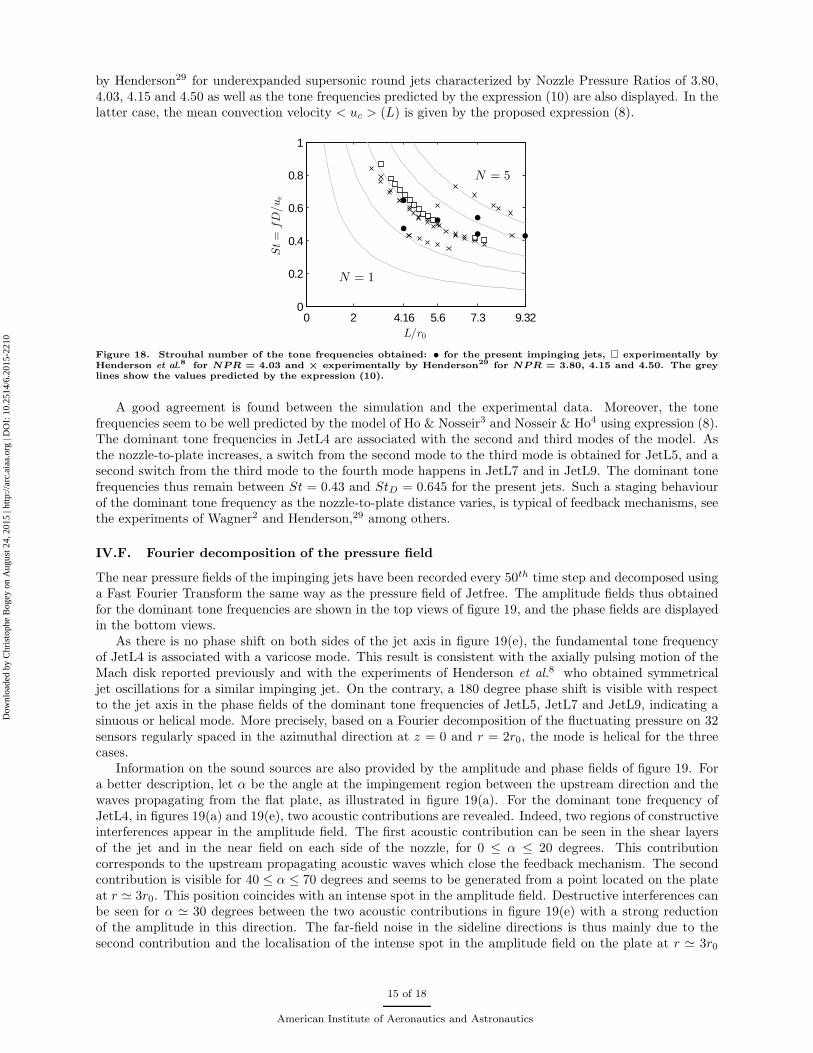
by Henderson29 for underexpanded supersonic round jets characterized by Nozzle Pressure Ratios of 3.80,4.03, 4.15 and 4.50 as well as the tone frequencies predicted by the expression (10) are also displayed. In thelatter case, the mean convection velocity < uc > (L) is given by the proposed expression (8).
0 2 4.16 5.6 7.3 9.320
0.2
0.4
0.6
0.8
1
L/r0
St=
fD/ue
N = 1
N = 5
Figure 18. Strouhal number of the tone frequencies obtained: • for the present impinging jets, � experimentally byHenderson et al.
8 for NPR = 4.03 and × experimentally by Henderson29 for NPR = 3.80, 4.15 and 4.50. The greylines show the values predicted by the expression (10).
A good agreement is found between the simulation and the experimental data. Moreover, the tonefrequencies seem to be well predicted by the model of Ho & Nosseir3 and Nosseir & Ho4 using expression (8).The dominant tone frequencies in JetL4 are associated with the second and third modes of the model. Asthe nozzle-to-plate increases, a switch from the second mode to the third mode is obtained for JetL5, and asecond switch from the third mode to the fourth mode happens in JetL7 and in JetL9. The dominant tonefrequencies thus remain between St = 0.43 and StD = 0.645 for the present jets. Such a staging behaviourof the dominant tone frequency as the nozzle-to-plate distance varies, is typical of feedback mechanisms, seethe experiments of Wagner2 and Henderson,29 among others.
IV.F. Fourier decomposition of the pressure field
The near pressure fields of the impinging jets have been recorded every 50th time step and decomposed usinga Fast Fourier Transform the same way as the pressure field of Jetfree. The amplitude fields thus obtainedfor the dominant tone frequencies are shown in the top views of figure 19, and the phase fields are displayedin the bottom views.
As there is no phase shift on both sides of the jet axis in figure 19(e), the fundamental tone frequencyof JetL4 is associated with a varicose mode. This result is consistent with the axially pulsing motion of theMach disk reported previously and with the experiments of Henderson et al.8 who obtained symmetricaljet oscillations for a similar impinging jet. On the contrary, a 180 degree phase shift is visible with respectto the jet axis in the phase fields of the dominant tone frequencies of JetL5, JetL7 and JetL9, indicating asinuous or helical mode. More precisely, based on a Fourier decomposition of the fluctuating pressure on 32sensors regularly spaced in the azimuthal direction at z = 0 and r = 2r0, the mode is helical for the threecases.
Information on the sound sources are also provided by the amplitude and phase fields of figure 19. Fora better description, let α be the angle at the impingement region between the upstream direction and thewaves propagating from the flat plate, as illustrated in figure 19(a). For the dominant tone frequency ofJetL4, in figures 19(a) and 19(e), two acoustic contributions are revealed. Indeed, two regions of constructiveinterferences appear in the amplitude field. The first acoustic contribution can be seen in the shear layersof the jet and in the near field on each side of the nozzle, for 0 ≤ α ≤ 20 degrees. This contributioncorresponds to the upstream propagating acoustic waves which close the feedback mechanism. The secondcontribution is visible for 40 ≤ α ≤ 70 degrees and seems to be generated from a point located on the plateat r ≃ 3r0. This position coincides with an intense spot in the amplitude field. Destructive interferences canbe seen for α ≃ 30 degrees between the two acoustic contributions in figure 19(e) with a strong reductionof the amplitude in this direction. The far-field noise in the sideline directions is thus mainly due to thesecond contribution and the localisation of the intense spot in the amplitude field on the plate at r ≃ 3r0
15 of 18
American Institute of Aeronautics and Astronautics
Dow
nloa
ded
by C
hris
toph
e B
ogey
on
Aug
ust 2
4, 2
015
| http
://ar
c.ai
aa.o
rg |
DO
I: 1
0.25
14/6
.201
5-22
10

Figure 19. Amplitude (top) and phase (bottom) fields obtained for the dominant tone frequency in (a) and (e) JetL4(StD = 0.645), (b) and (f) JetL5 (StD = 0.525) (c) and (g) JetL7 (StD = 0.44) and (d) and (h) JetL9 (StD = 0.43).
in figure 19(a) corresponds to the acoustic source found experimentally by Henderson et al.,8 for a similarimpinging jet, on an annular region on the plate, at r = 2.6r0. For the dominant tone frequencies of JetL5and JetL9, two acoustic contributions can similarly be noted. The second contribution seems to come froma point located on the plate at r ≃ 4r0. Finally, for the dominant tone frequency of JetL7, there is no cleardestructive interferences. Only one acoustic contribution appears to propagate from the region of impact.
V. Conclusion
In this paper the flow and near pressure fields of a free jet and four impinging underexpanded jets havebeen presented. They have a fully expanded Mach number ofMj = 1.56, a Reynolds number of Rej = 5×10⁴
and an exit Mach number of Me = 1. The free jet is first investigated. Flow snapshots of vorticity, densityand pressure as well as mean velocity fields are shown. The results, including the shock-cell structure,are consistent with experimental data, empirical and theoretical models. A tone frequency associated withscreech noise is obtained in the near pressure field of the jet. Its frequency and helical nature agree wellwith the model of Panda38 describing the formation of an hydrodynamic-acoustic standing wave and withthe measurements of Powell et al.39
The four impinging jets are then studied. Flow snapshots and the mean fields of the jets are presentedand compared with experimental data and with the results of the free jet. The convection velocity in theshear layers of the jets is evaluated. An expression yielding the mean convection velocity between the nozzleand the flat plate, for nozzle-to-plate distances L ranging from 2r0 to 10r0, is then proposed. The near
16 of 18
American Institute of Aeronautics and Astronautics
Dow
nloa
ded
by C
hris
toph
e B
ogey
on
Aug
ust 2
4, 2
015
| http
://ar
c.ai
aa.o
rg |
DO
I: 1
0.25
14/6
.201
5-22
10
pressure fields reveal several tone frequencies. A staging phenomenon of the main tone frequency with thenozzle-to-plate distance is found, which is typical of an aeroacoustic feedback mechanism occurring betweenthe nozzle lip and the flat plate. The different models existing for the mechanism are presented and themodel of Ho & Nosseir3 and Nosseir & Ho4 is applied using the expression (8) giving the average convectionvelocity < uc > (L). A very good agreement is found for the tone frequencies obtained. Finally, the natureof the dominant modes is identified. The results are consistent with experimental and numerical results.Notably, the strength of the feedback mechanism appears to be correlated with the formation of a Mach diskupstream of the plate, as noted by Henderson & Powell.6
In further work, the underlying physics of the feedback mechanism will be explored. This will be doneby extracting the most energetic modes by proper orthogonal decomposition and by using dynamic modedecomposition. The effect of the Mach disk position and motion on the feedback mechanism will then bestudied.
Acknowledgments
This work was performed using HPC resources of P2CHPD (Pole de Calcul Hautes Performances Dedies)and IDRIS (Institut du Developpement et des Ressources en Informatique Scientifique) under the allocation2014-2a0204 made by GENCI (Grand Equipement National de Calcul Intensif). This work was performedwithin the framework of the Labex CeLyA of Universite de Lyon, within the program ”Investissementsd’Avenir” (ANR-10-LABX-0060/ ANR-11-IDEX-0007) operated by the French National Research Agency(ANR).
References
1Powell, A., “On edge tones and associated phenomena”, Acta Acust. United Ac., Vol. 3, 1953, pp. 233-243.2Wagner, F.R., “The sound and flow field of an axially symmetric free jet upon impact on a wall”, NASA, 1971, NASA TT
F-13942.3Ho, C.M. and Nosseir, N.S., “Dynamics of an impinging jet. Part 1. The feedback phenomenon”, J. Fluid Mech., Vol. 105,
1981, pp. 119-142.4Nosseir, N.S. and Ho, C.M., “Dynamics of an impinging jet. Part 2. The noise generation”, J. Fluid Mech., Vol. 116, 1982,
pp. 379-391.5Tam, C.K.W. and Ahuja, K.K., “Theoretical model of discrete tone generation by impinging jets”, J. Fluid Mech., Vol. 214,
1990, pp. 67-87.6Henderson, B. and Powell, A., “Experiments concerning tones produced by an axisymmetric choked jet impinging on flat
plates”, J. Sound Vib., Vol. 168, No. 2, 1993, pp. 307-326.7Krothapalli, A., Rajkuperan, E., Alvi, F. and Lourenco, L., “Flow field and noise characteristics of a supersonic impinging
jet”, J. Fluid Mech., Vol. 392, 1999, pp. 155-181.8Henderson, B., Bridges, J. and Wernet, M., “An experimental study of the oscillatory flow structure of tone-producing
supersonic impinging jets”, J. Fluid Mech., Vol. 542, 2005, pp. 115-126.9Risborg, A. and Soria, J., “High-speed optical measurements of an underexpanded supersonic jet impinging on an inclined
plate”, 28th International Congress on High-Speed Imaging and Photonics, Vol. 7126, 2009.10Buchmann, N.A., Mitchell, D.M., Ingvorsen, K.M., Honnery, D.R. and Soria, J., “High spatial resolution imaging of a
supersonic underexpanded jet impinging on a flat plate”, Sixth Australian Conference on Laser Diagnostics in Fluid Mechanicsand Combustion, Vol. 116, 2011
11Mitchell, D.M., Honnery, D.R. and Soria, J., “The visualization of the acoustic feedback loop in impinging underexpanded
supersonic jet flows using ultra-high frame rate schlieren”, J. of visualization, Vol. 15, No. 4, 2012, pp. 333-341.12Kuo, C.Y. and Dowling, A.P., ‘Oscillations of a moderately underexpanded choked jet impinging upon a flat plate”, J.
Fluid Mech., Vol. 315, No. 4, 1996, pp. 267-291.13Powell, A., “The sound-producing oscillations of round underexpanded jets impinging on normal plates”, J. Acoust. Soc.
Am., Vol. 83, No. 2, 1988, pp. 515-533.14Dauptain, A., Cuenot, B. and Gicquel, L.Y.M., “Large eddy simulation of stable supersonic jet impinging on flat plate”,
AIAA J., Vol. 48, No. 10, 2010, pp. 2325-2338.15Dauptain, A., Gicquel, L.Y.M. and Moreau, S., “Large Eddy Simulation of Supersonic Impinging Jets”, AIAA J., Vol. 50,
No. 7, 2012, pp. 1560-1574.16Bogey, C. and Bailly, C., “A family of low dispersive and low dissipative explicit schemes for flow and noise computations”,
J. Comput. Phys., Vol. 194, No. 1, 2004, pp. 194-214.17Berland, J., Bogey, C., Marsden, O. and Bailly, C., “High-order, low dispersive and low dissipative explicit schemes for
multiple-scale and boundary problems”, J. Comput. Phys., Vol. 224, No. 2, 2007, pp. 637-662.18Bogey, C. and Bailly, C., “Large eddy simulations of transitional round jets: influence of the Reynolds number on flow
development and energy dissipation”, Phys. Fluids, Vol. 18, No. 065101, 2006, pp. 1-14.
17 of 18
American Institute of Aeronautics and Astronautics
Dow
nloa
ded
by C
hris
toph
e B
ogey
on
Aug
ust 2
4, 2
015
| http
://ar
c.ai
aa.o
rg |
DO
I: 1
0.25
14/6
.201
5-22
10

19Bogey, C. and Bailly, C., “Turbulence and energy budget in a self-preserving round jet: direct evaluation using large eddy
simulation”, J. Fluid Mech., Vol. 627, 2009, pp. 129-160.20Tam, C.K.W. and Dong, Z., “Wall boundary conditions for high-order finite-difference schemes in computational aeroa-
coustics”, Theor. Comput. Fluid Dyn, Vol. 6, 1994, pp. 303-32221Bogey, C., Marsden, O. and Bailly, C., “Large-eddy simulation of the flow and acoustic fields of a Reynolds number 105
subsonic jet with tripped exit boundary layers”, Phys. Fluids, Vol. 23, 2011, pp. 035104.22Bogey, C., Marsden, O. and Bailly, C., “Influence of initial turbulence level on the flow and sound fields of a subsonic jet
at a diameter-based Reynolds number of 105”, J. Fluid Mech., Vol. 701, 2012, pp. 352-385.23Bogey, C., de Cacqueray, N. and Bailly, C., “A shock-capturing methodology based on adaptative spatial filtering for
high-order non-linear computations”, J. Comput. Phys., Vol. 228, 2009, pp. 1447-1465.24de Cacqueray, N., Bogey, C. and Bailly, C., “Investigation of a High-Mach-Number Overexpanded Jet Using Large-Eddy
Simulation”, AIAA J., Vol. 49, No. 10, 2011, pp.2171-2182.25Mohseni, K. and Colonius, T., “Numerical treatment of polar coordinate singularities”, J. Comput. Phys., Vol. 157, No. 2,
2000, pp. 787-795.26Bogey, C., de Cacqueray, N. and Bailly, C., “Finite differences for coarse azimuthal discretization and for reduction of
effective resolution near origin of cylindrical flow equations”, J. Comput. Phys., Vol. 230, No. 4, 2011, pp. 1134-1146.27Lau, J.C., Morris, P.J. and Fisher, M.J., “Measurements in subsonic and supersonic free jets using a laser velocimeter”,
J. Fluid Mech., Vol. 93, 1979, pp. 1-27.28Tam, C.K.W., Jackson, J.A. and Seiner, J.M., “A multiple-scales model of the shock-cell structure of imperfectly expanded
supersonic jets”, J. Fluid Mech., Vol. 153, 1985, pp. 123-149.29Henderson, B., “The connection between sound production and jet structure of the supersonic impinging jet”, J. Acoust.
Soc. Am., Vol. 111, No. 2, 2002, pp. 735-747.30Addy, A.L., “Effects of axisymmetric sonic nozzle geometry on Mach disk characteristics”, AIAA J., Vol. 19, No. 1, 1981,
pp. 121-122.31Andre, B., Castelain, T. and Bailly, C., “Investigation of the mixing layer of underexpanded supersonic jets by particle
image velocimetry”, IJHFF, Vol. 50, 2014, pp. 188-200.32Prandtl, L., “Uber die stationaren Wellen in einem Gasstrahl”, 1904.33Tam, C.K.W. and Tanna, H.K., “Shock associated noise of supersonic jets from convergent-divergent nozzles”, J. Sound
Vib., Vol. 81, No. 3, 1982, pp. 337-358.34Pack, D.C., “A note on Prandtl’s formula for the wave-length of a supersonic gas jet”, The Quarterly Journal of Mechanics
and Applied Mathematics, Vol. 3, No. 2, 1950, pp. 173-181.35Harper-Bourne, M. and Fisher, M.J., “The noise from shock in supersonic jets”, AGARD Conference on Noise Mecha-
nisms, Vol. AGARD-CP-131, 1973, pp. 1-11.36Seiner, J.M. and Norum, T.D., “Aerodynamic aspects of shock containing jet plumes”, AIAA 6th Aeroacoustics confer-
ence, 1980, AIAA Paper 80-0965.37Westley, R. and Woolley, J.H., “The near field sound pressures of a choked jet during a screech cycle”, AGARD C.P.,
Vol. 42, 1969, pp. 23-1-23-13.38Panda, J., Raman, G. and Zaman, K.B.M.Q., “Underexpanded screeching jets from circular, rectangular and elliptic
nozzles”, 3th AIAA/CEAS Aeroacoustics conference, 1997, AIAA Paper 97-162339Powell, A., Umeda, Y. and Ishii, R., “Observations of the oscillation modes of choked circular jets”, J. Acoust. Soc. Am.,
Vol. 92, No. 5, 1992, pp. 2823-2836.40Arnette, S.A., Samimy, M. and Elliott, G.S., “On streamwise vortices in high Reynolds number supersonic axisymmetric
jets”, Phys. Fluids, Vol. 5, No. 1, 1993, pp. 187-202.
18 of 18
American Institute of Aeronautics and Astronautics
Dow
nloa
ded
by C
hris
toph
e B
ogey
on
Aug
ust 2
4, 2
015
| http
://ar
c.ai
aa.o
rg |
DO
I: 1
0.25
14/6
.201
5-22
10