large eddy simulation of a prefilming airblast atomizer g - cerfacs
TRANSCRIPT
ILASS – Europe 2013, 25th European Conference on Liquid Atomization and Spray Systems, Chania, Greece, 1-4 September 2013
1
Large Eddy Simulation of a prefilming airblast atomizer
G. Chaussonnet1, E. Riber1, O. Vermorel1, B. Cuenot1, S. Gepperth2, R. Koch2
1: CERFACS, France
2: Institut für Thermische Strömungmaschinen (ITS), Karlsruhe Institut of Technology (KIT), Germany
Abstract A Large Eddy Simulation of an academic experiment is performed with an unstructured, explicit in time, gaseous flow solver (AVBP). The configuration is a planar prefilming atomizer designed and manufactured at KIT-ITS. Results of the simulation are compared to experiments in terms of air velocity profiles, film thickness, drop size distribution and spray angle. The different forms of the liquid phase (film and spray) are described by a Lagrangian approach. The film model is built upon a depth-averaged method and a new approach for primary atomization is presented, based on the parametrization of a Rosin-Rammler function to describe the drop size distribution. Preliminary results indicate a good agreement with measurements, with regards to the predicted drop size probability function and the predicted spray angle.
Introduction The increasing scarcity of fossil fuel and the strengthening of environmental constraints are strong
motivations for the improvement of the combustion process in aeronautical gas turbines. One important prerequisite for a ‘more efficient’ combustion is the quality of the fuel spray that feeds the flame. Due to their thermal inertia, large droplets evaporate slowly. As a consequence, fuel-air mixing becomes insufficient and may be a significant source of unburned hydrocarbon emissions. On the contrary, fine droplets are rapidly evaporated and the fuel vapor better mixes with air before reaching the flame front, leading to a better-controlled combustion. A precise characterization of the drop size distribution in the spray is thus a necessary input to predict the flame structure and topology. This becomes even more critical for transient phenomena such as ignition or extinction.
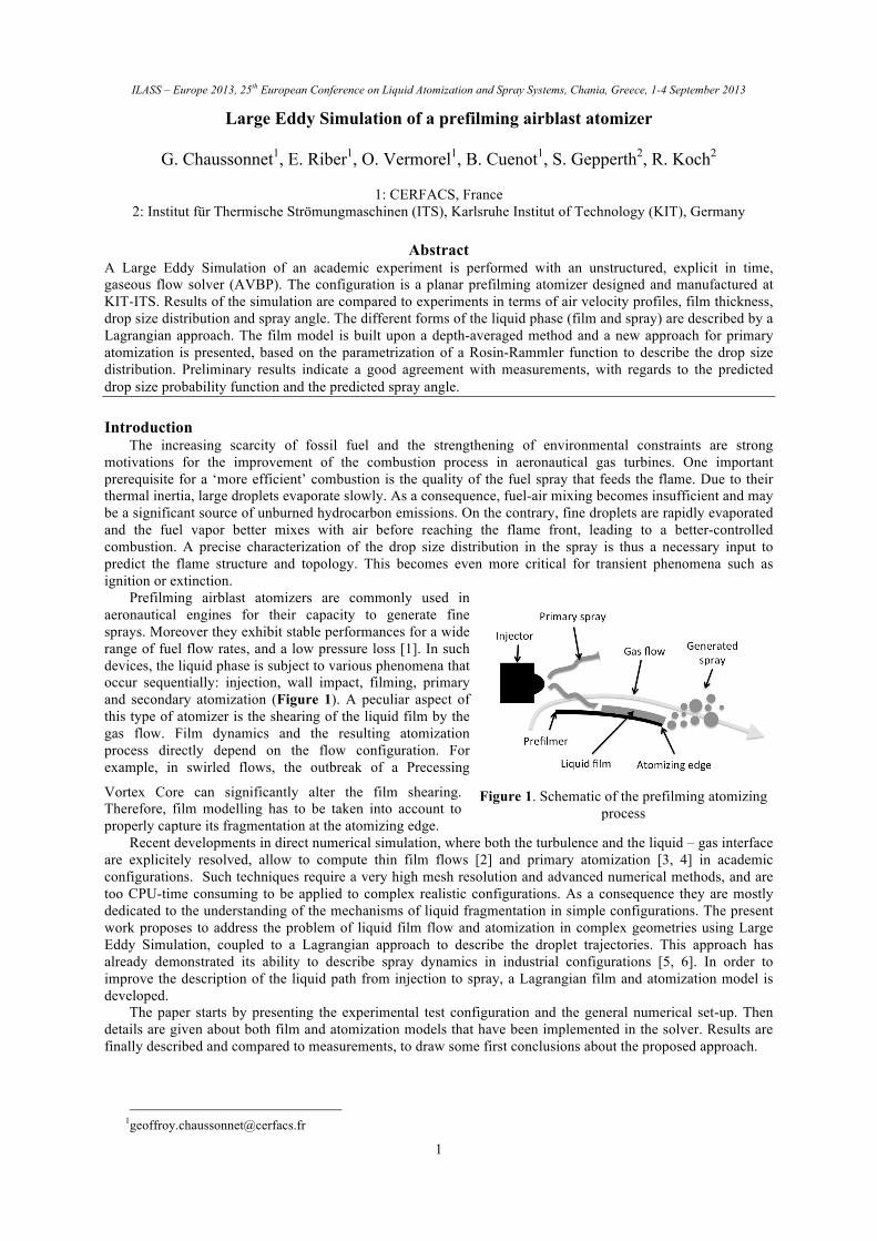
Prefilming airblast atomizers are commonly used in aeronautical engines for their capacity to generate fine sprays. Moreover they exhibit stable performances for a wide range of fuel flow rates, and a low pressure loss [1]. In such devices, the liquid phase is subject to various phenomena that occur sequentially: injection, wall impact, filming, primary and secondary atomization (Figure 1). A peculiar aspect of this type of atomizer is the shearing of the liquid film by the gas flow. Film dynamics and the resulting atomization process directly depend on the flow configuration. For example, in swirled flows, the outbreak of a Precessing
Vortex Core can significantly alter the film shearing. Therefore, film modelling has to be taken into account to properly capture its fragmentation at the atomizing edge.
Recent developments in direct numerical simulation, where both the turbulence and the liquid – gas interface are explicitely resolved, allow to compute thin film flows [2] and primary atomization [3, 4] in academic configurations. Such techniques require a very high mesh resolution and advanced numerical methods, and are too CPU-time consuming to be applied to complex realistic configurations. As a consequence they are mostly dedicated to the understanding of the mechanisms of liquid fragmentation in simple configurations. The present work proposes to address the problem of liquid film flow and atomization in complex geometries using Large Eddy Simulation, coupled to a Lagrangian approach to describe the droplet trajectories. This approach has already demonstrated its ability to describe spray dynamics in industrial configurations [5, 6]. In order to improve the description of the liquid path from injection to spray, a Lagrangian film and atomization model is developed.
The paper starts by presenting the experimental test configuration and the general numerical set-up. Then details are given about both film and atomization models that have been implemented in the solver. Results are finally described and compared to measurements, to draw some first conclusions about the proposed approach.
Figure 1. Schematic of the prefilming atomizing process

25th ILASS – Europe 2013 Large Eddy Simulation of a prefilming airblast atomizer
2
Experimental investigations The experimental rig designed at the ITS by Gepperth et al. [7, 8] has been chosen to test the model. It
consists of a wing-shaped pre-filmer (Figure 2), placed in a channel. Liquid is injected at the surface of the pre-filmer via fifty equidistantly distributed holes, located 45 mm upstream the pre-filmer tip. To enhance accessibility for measurements, and to reduce the configuration complexity, the pre-filmer and the channel walls are planar, but still considered representative of the annular geometry encountered in real systems. The high gas velocity entrains the liquid towards the atomizing-edge of the pre-filmer, i.e. in the Z-direction, and induces high shear at the film surface. A thin film forms, that wets homogeneously the pre-filmer, before full atomization at the pre-filmer edge. No atomization is observed from the film surface before reaching the edge of the pre-filmer. Measurements combine particle and ligament tracking velocimetry, and blacklight illumination. More details can be found in [7]. All experiments have been performed at ambient conditions, summarized in Table 1. The air and liquid flow rates were varied to study various regimes. Various liquids were also tested to measure the impact of their transport properties on the film and atomization behaviours.
Measurements showed that the mean film thickness decreases as the gas velocity increases (due to a larger interface shear stress), and increases with liquid viscosity. Under the investigated conditions, the breakup process was observed to always follow three steps. First, a reservoir is formed at the atomizing edge, fed by the liquid coming from the film. Second, under the action of aerodynamics, bubbles and ligaments form out of this reservoir. When the bubble bursts (like a bag-breakup process in secondary atomization [9]), small droplets are produced. The rim of the bag remains attached to the reservoir and finally disintegrates into large droplets. The drop size distribution of the generated spray has been measured in a series of test cases to evaluate the impact of several operating conditions. The pre-filmer length (Lp), the film thickness (hf), the liquid viscosity (µl) and the surface liquid flow rate ( s ) have a minor effect on the drop-size distribution, even if the latter induces a significant increase in the number of fragmentation events [8]. The three main influencing parameters are: a) the momentum flux of the gas M = ρgug
2 which sizes the quantity of momentum transferred from the gas to the liquid, b) the surface tension of the liquid σ which influences the volume of liquid accumulation at the pre-filmer edge as well as the ligament size and c) the atomizing edge thickness hp which partly controls the volume of the accumulated liquid. Shadowgraphs and high-speed diagnostics allow to measure the diameter (or the equivalent diameter for near spherical structures) in the primary atomization zone. From this experiments, Gepperth et al. [8] provide a droplet number and volume probability density function for different gas velocities, liquid properties and atomizing edge thicknesses. For every operating condition, the resulting PDF is compared to the Rosin-Rammler distribution [10]:
F0 (d) =1− exp −dm"
#$
%
&'q(
)**
+
,--⇔ f0 (d) =
qdq−1
mq exp −dm"
#$
%
&'q(
)**
+
,--
(1)
Mean air velocity ug 20 – 70 m/s Air temperature T 298 K Air density ρg 1.21 kg/m3 Air kinematic viscosity νg
1.5 x 10⁻⁵ m2/s Liquid density ρl 770*, 1008** kg/m3 Liquid surface tension σ 0.0275*, 0.0466**
kg/s2 Surface liquid flow rate s 12.5 – 75 mm2/s
Table 1. Operating conditions, from [8]. *Shellsol D70, **a volume mixture of 50% of propanediol and 50%
of water, labelled ‘1:1 W-P’ in the following
Figure 3. Volume PDF (Shellsol D70, hp = 1 mm, ug = 50 m/s)
Figure 2. Schematic of the experimental configuration, from [8]
25th ILASS – Europe 2013 Large Eddy Simulation of a prefilming airblast atomizer
3
where f0 (d) is the probability density function and F0 (d) its cumulative density function. The volume probability density function is defined as f3(d) = d3 ⋅ f0 (d) and agrees well with the experimental data (Figure 3) for all investigated conditions. The Rosin-Rammler distribution depends on two parameters: the shape q and the scale m. However the set (q,m) ensuring the best experimental fitting is different for each condition.
Models In order to describe the targeted phenomena, it is necessary to take into account transfers between both
phases, i.e. to couple the gas and liquid flow solvers. No thermal effects have been observed in the considered configuration so that the energy equation will be omitted in the following. In addition, droplet evaporation is neglected and the gas will be considered as a single-species mixture. Gaseous phase solver The unstructured LES code AVBP explicitly solves the filtered compressible Navier–Stokes equations that are here simplified to the continuity and momentum equations [11]:
∂ρ∂t+∂ρ ui∂x j
= 0 and ∂ρ ui∂t
+∂ρ ui uj∂x j
=∂∂x j
pδij −τ ij −τ ijsgs#$ %&+ smo,i (2)
The symbol ⋅ states for spatial filtering and ⋅ for mass-weighted Favre filtering. Einstein’s summation convention is applied over repeated indices and δij denotes the Kronecker symbol. The inter-phase momentum
exchange term smo,i is detailed below. τ ij stands for the laminar filtered stress tensor. The subgrid unclosed term is classically expressed by an eddy-viscosity approach and the turbulent viscosity is computed via the dynamic Smagorinsky model. Liquid phase solver The liquid phase is assumed to be diluted, and heavier than the carrier phase. Droplet diameters are considered much lower than any other resolved flow characteristic scale, to allow point-source approximation. In these conditions, drag is the only significant momentum transfer type, and the Lagrangian governing equations of motion are:
dxp,idt
= up,i and dup,idt
=fp,imp,i
(3)
where the subscript p refers to the droplet and xp,i , up,i and mp represent its position, velocity and mass,
respectively. The force acting upon the droplet fp,i is expressed by the Stokes drag extended by Schiller and Naumann’s correlation [12]:
fp,i = −mp
τ p
up,i − ug@p,i( ) with: τ p =ρld
2
18µg
11+ 0.15Re p
0.687 (4)
where ug@p,i is the gaseous velocity seen by the droplet and is computed as a linear interpolation from the filtered
gas field at the droplet position, without accounting for the subgrid scale contribution. The momentum transfer smo,i is calculated at each node as the sum of the drag force of all particles located in all elements containing the considered node, weighted by the conservative projector wp@n
:
smo,i = −1V
wp@n ⋅ fp,ip∑ (5)
Lagrangian film model Liquid thin film flows have been studied in various industrial contexts. In piston engines, Foucart et al. [13]
used an Arbitrary Lagrangian Eulerian approach, while O’Rourke and Amsden [14] applied a Lagrangian Particle Model. In aeronautical burners, Elsäßer et al. [15] and Ebner et al. [16] described the film flow with an Eulerian approach. The common denominator of these studies is the use of height-averaged film equations. The underlying idea is that the film thickness is negligible compared to all gaseous macroscopic length scales, and is usually referred to as thin film hypothesis. Most previous studies of liquid films were conducted in a RANS approach. In the present work, the model is embedded in a LES solver, resulting in a liquid film that undergoes turbulent fluctuations.
As the film is made of liquid fuel and its Reynolds number is about 100, the film flow is supposed laminar and incompressible. The characteristic time scale of the film flow is the momentum diffusion time along the film thickness. Since this time scale is lower than the film convective time, the flow is supposed steady, i.e. it follows

25th ILASS – Europe 2013 Large Eddy Simulation of a prefilming airblast atomizer
4
hfilm
Htot
velocity profile
interface
hfilm
Gaseous solver Film solver
instantaneously the shear stress variation imposed by the gas. Finally, because of the thin film hypothesis, longitudinal gradients (except the pressure gradient) are neglectable compared to the wall normal ones.
In addition, and in the context of aeronautical combustors, the velocity ratio of the liquid film and the gas flow is supposed to stay below 100. The film may then be seen as stationary in comparison to the gas. Coupling of this assumption to the thin film hypothesis leads to a stationary boundary condition at the liquid-gas interface. The local shear stress can therefore be considered as equal to the wall
shear stress in the absence of a film. This may not be true if the film surface presents strong wrinkling and instabilities,
introducing some surface roughness or even deformation, but this assumption will be used here as a first attempt. The physical consequence is a one-way coupling approach, where the gas flow influences the film flow without feedback from the liquid to the gas. The resulting approach is depicted in Figure 4: the film flow profile is not solved, the “liquid film boundary condition” being derived from a model as described below. Compiling all assumptions leads to the depth-averaged film velocity magnitude:
uf =hf2µl
τ w −hf2
3µl
dpdx
(6)
Equation (6) states that the film motion is a result of the film surface shear stress and the pressure gradient within the film. The shear term being proportional to the film thickness hf, and the pressure gradient term to hf
2, the pressure gradient impact is assumed to be negligible compared to the shear stress. Primary atomization model
In the present study, a new approach is proposed to model primary atomization in pre-filming configurations, called PAMELA (Primary Atomization Model for prEfilming airbLAst injectors). It is based on the transverse instability prediction, initiated by Hong et al. [17] and Varga et al. [18]. It is calibrated to fit the experimental results of Geperth et al. [8]. The basic idea is to describe the drop size distribution of the generated spray by a Rosin-Rammler distribution whose parameters (q,m) are expressed from the operating conditions. The main parts of the model are explained in the following.
Expression of m In configurations of planar liquid sheets [19, 20] as well as axial jets [17, 21], experiments have shown that a transverse instability develops prior to the atomization, and that the Sauter mean diameter (D32
) of the generated spray is proportional to this instability length scale λT:
D32exp =C ⋅λT (7)
The transverse instability is also visible in the present experiment and its length scale is estimated using Hong’s approach. Liquid structures, which are immersed in the main flow stream, are accelerated by the gas flow through the drag force. This streamwise acceleration generates a Rayleigh-Taylor instability that propagates in the spanwise direction. In the present configuration where the liquid fragmentation occurs at the pre-filmer edge, the size of the accelerated liquid structure is supposed to be proportional to the edge thickness. This leads to a transverse instability wavelength estimated as:
λRT = 2π6σ ⋅ αhp( )
Cdρg ug −uc( )2
(8)
where Cd is the drag coefficient of the liquid structure, reported to be close to one [20]. The constantα is
between 0 and 1 and represents the characteristic length of accelerated liquid compared to the pre-filmer thickness. It is set to 0.67 from the observations of Müller et al. [22]. The interface velocity is denoted by uc . From the Rosin-Rammler distribution (Eq.(1)), the Sauter mean diameter (D32
RR ) writes:
D32RR =m
Γ 3 / q+1( )Γ 2 / q+1( )
(9)
where Γ is the Gamma function. Combining Eqs. (7), (8) and (9) leads to the final expression of m that depends on the three parameters M = ρgug
2 , σ and hp :
Figure 4. One-way coupling hypothesis on a flat interface. a) Real configuration. b) Modelled configuration.

25th ILASS – Europe 2013 Large Eddy Simulation of a prefilming airblast atomizer
5
m = 2πC6σ ⋅ αhp( )
Cdρg ug −uc( )2 ⋅Γ 2 / q+1( )Γ 3 / q+1( )
(10)
Expression of q Experimental results indicate a dependency of the parameter q on the Weber number expressed with gaseous aerodynamic force:
We =ρgy70u70
2
σ (11)
where u70 is equal to 70% of the free stream velocity and y70 represents the height in the boundary layer where the local velocity is equal to u70 . Both values correspond to experimental observations, where the liquid is accelerated at a vertical position above the pre-filmer where the local gas velocity is approximately 70% of the free stream velocity, taken as the bulk velocity in the present experiment. The shape parameter q also depends on the pre-filmer thickness. Finally, q is expressed as:
q We,hp( ) = κWe
+ ahp + b( ) (12)
where κ, a and b are model constants. The linear form (ahp + b) in Eq. (12) derives from the fact that only two different pre-filmer thicknesses have been investigated. Model constants The four model constants are fitted with a multi-variate optimization technique where the test values are the Sauter mean diameter and the q parameter. The varying parameters are the pre-filmer thickness (1 and 2.5 mm), the type of liquid (see Table 1) and the gas velocity ug . The result is given in Table 2.
C, Eq. (7) κ , Eq. (12) a, Eq. (12) b, Eq. (12) 0.1166 1.76 112 m-1 -0.043
Table 2. Model constants of PAMELA
Results of PAMELA are shown in Figure 5, obtained for a pre-filmer thickness of 2.5mm and the liquid 1:1 W-P. Figure 5a) illustrates the influence of the gas velocity onto D32 and the mean volume diameters DV10 and DV90 (drop diameter such that 10% and 90% of the total spray volume is in droplets of smaller diameter). DV10 and D32 are well recovered while DV90 is overestimated for low velocities with a maximum deviation of 20%. Figure 5b) represents the volume PDF for a mean gas velocity ug= 70 m/s. The trend of the distribution is well recovered
and presents an absolute surface deviation ( f3mod (d)− f3
exp (d)∫ d(d) ) of 14.6%.
Figure 5. a) Mean diameters evolution with gas velocity. Lines: PAMELA, symbols: experiment b) Volume
PDF for 1:1 W-P liquid, hp = 2.5 mm, ug = 70 m/s.
Numerical Set-up Two-phase Large Eddy Simulations of the pre-filmer experiment have been performed with the code AVBP,
an unstructured, compressible, explicit in time, flow solver [11], including a Lagrangian approach for the liquid phase [23]. The computational mesh contains 1.5 millions of tetrahedra, with a characteristic cell size in the atomization region of 0.1 mm. A mid-plane Y-cross section of the mesh, zoomed at the pre-filmer edge region, is shown in Figure 6. Boundary conditions consist in a turbulent gas velocity inlet with a turbulent intensity of 10%, an atmospheric pressure outflow and solid law-of-the-wall. In Figure 7, the mean gaseous velocity profiles on a vertical line located at 0.3 mm from the atomizing edge (dashed line in Figure 6) are compared for three bulk velocities. Both horizontal and vertical components agree well with the experimental data. However the predicted vertical velocity profiles show a slight discrepancy illustrated by additional inflexion points. Those are
a) b)

25th ILASS – Europe 2013 Large Eddy Simulation of a prefilming airblast atomizer
6
related to the counter rotating eddies that lie in the recirculation zone. These eddies are small (~ 0.5 mm), and any uncertainty on the measurement device position (~ 0.1 mm) induces a large variation in the measured velocity profile.
The film thickness evolution with air velocity is shown in Figure 8. Although the film thickness is not well recovered, the film model succeeds to capture the correct dependence on air velocity and liquid viscosity. Note the factor 2 in film thickness between both liquids, to be related to the factor 4 between their viscosities. Indeed, from Eq. (6) it can be seen that the film thickness is proportional to the square root of the liquid viscosity. The large over-estimation of the film thickness results from the strong one-way coupling hypothesis: in reality the liquid surface is not flat and some waves can alter the gas boundary layer and the interface shearing. To account for this phenomenon, Elsäßer et al. [15] proposed a method to model the feedback from the film to the gas. Moreover, the wrong estimation of the wall shear stress may also be related to the weakness of LES to predict accurately shear stress and pressure loss [24]. However the film thickness has a minor influence on the spray population, so that the observed deviation is not an issue for the prediction of atomization.
This is confirmed by the plots of DV10 and D32 in Figure 9a, showing good agreement with the experiment. Because of a lower statistical convergence, larger diameters (DV90) are less representative. The drop size PDF, depicted in Figure 9b is accurately reconstructed for two different gas velocities. Here again, the poor statistical convergence at high diameters is responsible for a noisy behaviour. Figure 10a presents a superposition of a series of experimental snapshots, to be compared to the numerical spray in Figure 10b). The spray angle is in good agreement with the experiment but the width of the spray just behind the atomizing edge region is slightly under-predicted. This is due to the flapping of the liquid accumulation at the edge, not described in PAMELA, that forms droplets with a zero velocity.
Conclusions An academic experiment devoted to the study of pre-filming atomization in the case of a planar geometry
has been simulated with the use of Large Eddy Simulation and Lagrangian particle tracking. To describe pre-filming atomization typical phenomena, a film model and an atomisation model have been developed and implemented in the solver AVBP.
Figure 6. Mid-plane Y-cut of the computational mesh in the atomizing edge region Figure 7. Comparison of experimental (symbols) and
numerical (lines) results for single phase gas velocity profiles (0.3 mm downstream the atomizing edge)
Figure 8. Film thickness evolution with air velocity
Figure 9. a) Mean diameters evolution with air velocity. Lines: PAMELA, symbols: experiment b) Volume PDF for Shellsol D70 on a
1 mm thick pre-filmer
Figure 10. Spray visualisation. a) Experiment. b) Simulation.
a) b)
b) a)

25th ILASS – Europe 2013 Large Eddy Simulation of a prefilming airblast atomizer
7
The film model is capable to represent the trends in the film thickness evolution with regards to the interface shearing (depending on the gas velocity) and to the liquid viscosity. However the film thickness is not well reproduced, with a relative error that peaks to a factor 3. This is explained by first, the neglected retroaction of the liquid on the gas and second, the difficulty that LES faces to accurately predict wall shear stress and pressure loss.
The atomization model (PAMELA) is calibrated on the experimental results presented in Gepperth et al. [8] and allows to predict the correct distribution of droplet diameters in the generated spray. Simulations and experimental results are in good agreement for all tested conditions. As the fragmentation mechanism in real annular air-blast atomizers is expected to be similar to the one observed in the present configuration, the atomization model proposed in this work is believed to provide an accurate description of the spray topology in real combustors, which constitutes the next step of this study.
Acknowledgements The research leading to these results has received funding from the European Union Seventh Framework
Programme (FP7/2007-2013) under grant agreements n°265848 and n° ACP8-GA-2009-234009; and was conducted within the FIRST and KIAI projects. This work was performed using HPC resources from GENCI-CINES (Grant 2013- x20132b5031).
Nomenclature Symbols q shape parameter of the Rosin- σ surface tension [kg/s2] Cd drag coefficient [-] Rammler function [-] τij stress tensor [N/m2] d diameter [m] u velocity [m/s] τp particle response D32 Sauter mean diameter [m] u70 70% velocity of the free stream time [s] DV10 drop diameter such that 10% total velocity [m/s] τw wall shear stress liquid volume is smaller droplets uc convection velocity of [Pa] [m] the interface [m/s] DV90 drop diameter such that 90% total s surface film flow rate per unit Subscripts liquid volume is smaller droplets length [mm2/s] f Film [m] y70 height such that local velocity g Gas f volume force [N/m3] is equal to u70 [m] l Liquid f0,f3 number and volume dropsize We Weber number [-] p Prefilmer PDF [1/m] δij Kronecker symbol F0 number dropsize Cumulative λT transverse instability Superscripts Density Function [-] wavelength [m] exp Experience h thickness [m] λRT Rayleigh-Taylor instability mod Model L length [m] wavelength [m] m scale parameter of the Rosin- µ dynamic viscosity [Pa.s] Acronym Rammler function [m] ν kinematic viscosity [m2/s] PDF Probability M momentum flux [N/m2] ρ density [kg/m3] Density Function
References [1] Lefebvre, A. H., (1989). Atomization and Spray, Ed. Norman Chigier. [2] Lan, H., Friedrich, M., Armaly, B. F., & Drallmeier, J. A. (2008). International Journal of Heat and Fluid Flow 29, 449 - 459. [3] Fuster, D., Bagué, A., Boeck, T., Le Moyne, L., Leboissetier, A., Popinet, S., Ray, P., Scardovelli, R., & Zaleski, S. (2009). International Journal of Multiphase Flow 35, 550--565. [4] Lebas, R., Menard, T., Beau, P., Berlemont, A., & Demoulin, F. X. (2009). International Journal of Multiphase Flow 35, 247--260. [5] Ham, F., Apte, S. V., Iaccarino, G., Wu, X., Herrmann, M., Constantinescu, G., Mahesh, K., & Moin, P. (2003). Center for Turbulence Research Annual Briefs, 139-160. [6] Jaegle, F., Senoner, J.-M., Garcia, M., Bismes, F., Lecourt, R., Cuenot, B., & Poinsot, T. (2011). Proc. of the Comb. Inst. 33, 2099-2107. [7] Gepperth, S., Guildenbecher, D., Koch, R., & Bauer, H. (2010). 23rd Annual Conf. on Liq. Atomization and Spray Syst. [8] Gepperth, S., Müller, A., Koch, R., & Bauer, H. (2012). 12th Triennial International Conf. on Liq. Atomization and Spray Syst. [9] Rimbert, N. & Castanet, G. (2011).Physical Review E 84, 016318. [10] Babinsky, E. & Sojka, P. E. (2002). Progress in Energy and Combustion Science 28, 303-329. [11] Gourdain, N., Gicquel, L., Montagnac, M., Vermorel, O., Gazaix, M., Staffelbach, G., Garcia, M., Boussuge, J., & Poinsot, T. (2009). Computational Science & Discovery 2, 015003. [12] Schiller, L. & Nauman, A., (1935). VDI Zeitung 77, 318-320. [13] Foucart, H., (1998). PhD thesis, Université de Rouen. [14] O'Rourke, P. & Amsden, A. A. (1996). SAE Technical Paper. [15] Elsäßer, A. (1998). PhD thesis, Department of Thermal Turbomachinery, Karlsruhe Institute of Technology. [16] Ebner, J., Schafer, O., Schober, P., & Wittig, S. (2003). Proc. of the 9th International Conf. on Liq. Atomization and Spray Syst. [17] Hong, M., Cartellier, A., & Hopfinger, E. (2002). Proc. 4th Int. Conf. on Launcher Technology” Space Launcher Liq. Prop.”, 3--6. [18] Varga, C., Lasheras, J. C., & Hopfinger, E. (2003). Journal of Fluid Mechanics 497, 405--434. [19] Raynal, L. (1997). PhD thesis, Université de Grenoble 1. [20] Rayana, F. B., Cartellier, A., & Hopfinger, E. (2006). Proc. of the international conf. on Liq. Atomization and Spray Syst. 27. [21] Marmottant, P. & Villermaux, E. (2001). Actes du colloque de synthèse du groupe de recherche CNES/CNRS/ONERA/SENECMA. [22] Müller, A., Meier, R., Schäfer, O., & Wittig, S. (2004). DFG-Tagung - Atomization and Spray Processes. [23] Garcia, M. (2009). PhD thesis, Institut Polytechnique de Toulouse. [24] Barré, D., Kraushaar, M., Staffelbach, G., Moureau, V., & Gicquel, L. Y. M. (2013). Comptes Rendus de l'Académie des Sciences - Mécanique 341, 277-287.