large eddy simulation (les) applied to advanced engine ...– detailed thermodynamics, transport and...
TRANSCRIPT

Large Eddy Simulation (LES) Applied to Advanced Engine Combustion Research
Joseph Oefelein, Guilhem Lacaze, Layal Hakim
Combustion Research FacilitySandia National Laboratories, Livermore, CA 94551
Support Provided by the DOEOffice of Energy Efficiency and Renewable Energy
Vehicle Technologies Programis Gratefully Acknowledged
This presentation does not contain any proprietary, confidential, or otherwise restricted information
Project ID: ACE007Date: June 8, 2016
1

Overview
• Project provides fundamental research that supports advanced engine development
• Focused on next generation simulations, models, flow-solvers, and workflow for model validation using Large Eddy Simulation
• Project scope, direction, and continuation evaluated annually
• Two sets of barriers addressed– Lack of fundamental knowledge of both
Diesel and GDI combustion regimes– Understanding coupled effects of fuel-
injection, turbulent-mixing, heat-transfer, chemical-kinetics, and geometry on combustion and emissions over broad operating ranges
– Lack of predictive models for engine combustion design and control
– Efficient and routine use of advanced High-Performance-Computing (HPC) codes and computer architectures
• Total Project Funding− FY15 – $390K− FY16 – $390K
Timeline
Budget
Barriers
• CRF Engine and UQ Groups• Penn State, Stanford, Michigan
CERFACS (e.g., DOE/NSF/FOA)• DOE Office of Science• Project Lead: Joe Oefelein
Partners
1
2
2
Relevance … need for advanced model development is well recognized
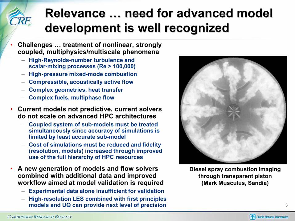
• Challenges … treatment of nonlinear, strongly coupled, multiphysics/multiscale phenomena
– High-Reynolds-number turbulence and scalar-mixing processes (Re > 100,000)
– High-pressure mixed-mode combustion– Compressible, acoustically active flow– Complex geometries, heat transfer– Complex fuels, multiphase flow
• Current models not predictive, current solvers do not scale on advanced HPC architectures
– Coupled system of sub-models must be treated simultaneously since accuracy of simulations is limited by least accurate sub-model
– Cost of simulations must be reduced and fidelity (resolution, models) increased through improved use of the full hierarchy of HPC resources
• A new generation of models and flow solvers combined with additional data and improved workflow aimed at model validation is required
– Experimental data alone insufficient for validation– High-resolution LES combined with first principles
models and UQ can provide next level of precision
Diesel spray combustion imaging through transparent piston (Mark Musculus, Sandia)
3

Deficiencies in model development have been demonstrated for years
Projected Mass Distribution
0D 3D Spray-A(0.4ms)
Inconsistencies in non-reacting calculations observed in all ECN workshops (here ECN4)• Correct vapor penetration but large scatter in other quantities
Similarly, large scatter is observed in reacting calculations • Large variability between chemical mechanisms and shock tube data, and scatter in ignition delay (ID) in Spray-A simulations
There is a distinct lack of discriminating data due to many competing effects in both models and numerical methods ...4

Milestones
• Subtask 6.1 (FY2016-17) LES of transient Diesel fuel injection, ignition, combustion, and emissions
• Subtask 6.2 (FY2016-18) LES of transient Gasoline Direct Injection spray dynamics, combustion, and emissions
• Subtask 6.3 (FY2017-18) LES of the LTGC engine with emphasis on temperature stratification
• Subtask 6.4 (FY2018) LES of the LTGC engine including direct injection and combustion
Milestones aimed toward detailed calculations in (optical) engine geometries with advanced treatment of detailed physics and turbulence phenomena not account for in current codes; e.g., “low”-pressure versus “high”-pressure fuel injection processes 5

Approach/Strategy
Basic AppliedDOE Basic Energy Sciences Program
TNF Workshopwww.ca.sandia.gov/TNF
DOE Vehicle Technologies Program
Engine Combustion Networkwww.ca.sandia.gov/ECN
Detailed jet flame data for model development but low Reynolds number
and simple fuelsRe ≈ O(10,000)
Device relevant measurements but
limited due to complex geometry, flow, and fuels
Re > O(100,000)
Next Generation Code Framework (RAPTOR)
• Complement advanced experiments with unique simulation capabilities using high-fidelity LES and first-principles models
– Match detailed geometric and operating conditions, retain full governing physics– Establish one-to-one correspondence between measured and modeled results– Validate using available experimental data, then extract
• Data and insights not available from experiments alone• Data required to develop affordable models for engineering
• Use full hierarchy of high-performance computing resources (both local and DOE platforms) with next generation massively-parallel code framework 6

Theoretical-Numerical Framework (RAPTOR: A first-principles DNS solver optimized for LES)
Near linear scalability beyond 100,000 cores
11
• Theoretical framework … (Comprehensive physics)
– Fully-coupled, compressible conservation equations
– Real-fluid equation of state (high-pressure phenomena)
– Detailed thermodynamics, transport and chemistry
– Multiphase flow, spray (Lagrangian-Eulerian)
– Dynamic SGS modeling (No Tuned Constants)
• Numerical framework … (High-quality numerics)
– Staggered finite-volume differencing (non-dissipative, discretely conservative)
– Dual-time stepping with generalized preconditioning (all-Mach-number formulation)
– Detailed treatment of geometry, wall phenomena, transient BC’s
• Hybrid-parallel programming model … (Highly-scalable)
– Demonstrated performance on hierarchy of HPC platforms (e.g., scaling on ORNL TITAN)
– MPI at block/node level, OpenMP/OpenACC at flux/operator level, GPU acceleration of sub-model kernels (properties, chemistry, turbulence, etc.)
7
RAPTOR selected for ORNL Center for Accelerated Application Readiness
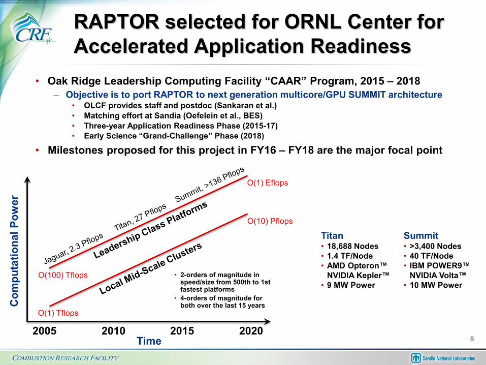
• Oak Ridge Leadership Computing Facility “CAAR” Program, 2015 – 2018– Objective is to port RAPTOR to next generation multicore/GPU SUMMIT architecture
• OLCF provides staff and postdoc (Sankaran et al.)• Matching effort at Sandia (Oefelein et al., BES)• Three-year Application Readiness Phase (2015-17)• Early Science “Grand-Challenge” Phase (2018)
• Milestones proposed for this project in FY16 – FY18 are the major focal point
2005 20202010 2015Time
Com
puta
tiona
l Pow
er
O(1) Tflops
O(100) Tflops
O(1) Eflops
O(10) Pflops
• 2-orders of magnitude in speed/size from 500th to 1st fastest platforms
• 4-orders of magnitude for both over the last 15 years
Titan• 18,688 Nodes• 1.4 TF/Node• AMD Opteron™
NVIDIA Kepler™• 9 MW Power
Summit• >3,400 Nodes• 40 TF/Node• IBM POWER9™
NVIDIA Volta™• 10 MW Power
8

Technical Accomplishmentsand Progress
9

10
Advanced grid generation •! Complex geometry and topologies •! Dynamic mesh movement, AMR
Liquid atomization, spray formation •! Level-set/volume-of-fluid development •! Lagrangian treatment of dense sprays
Lagrangian particle dynamics •! Secondary breakup, two-way coupling •! Multicomponent drop vaporization
Multicomponent mixture properties •! Real-fluid gas/liquid equations of state •! Detailed thermodynamics and transport
Turbulence and scalar mixing •! Dynamic modeling, inverse methods •! Implicit, explicit filtering
Turbulent combustion •! Turbulence-chemistry interactions •! Complex fuels, mixed mode combustion
Chemical kinetics and emissions •! Detailed, skeletal mechanisms •! Optimized model mechanisms
Heat transfer and wall turbulence •! Thermal radiation-turbulence interactions •! Transient wall-flow interactions
In-situ visualization and analysis •! Massively-parallel data management •! Advanced mathematical data reduction
First Principles LES (RAPTOR) •! Comprehensive physics (accuracy) •! Non-dissipative numerics (optimal for LES) •! Complex geometry (high-quality) •! Massively-parallel (highly-scalable)
Mod
el L
ibra
ry (P
orta
ble)
Mat
h Li
brar
y (P
orta
ble)
Syst
em L
ibra
ry
Data Processing Interface
Output
Lagrangian Particle Integrator
Spatial Differencing Operators
Staggered Finite-Volume Scheme (Body-Fitted Coordinates)
Multistage Integrator
Preconditioned Dual-Time-Stepping
(All-Mach-Number Formulation)
Input
Grid Interface (Complex Geometry)
SMP
Shar
ed M
emor
y Sh
ell (
Ope
nMP/
Ope
nAC
C)
SPM
D D
istr
ibut
ed C
omm
unic
atio
n Sh
ell (
MPI
) U
nstr
uctu
red
Mul
tiblo
ck C
onne
ctiv
ity
Detailed results and physical insights
Technology Transfer Mechanisms •! Development of advanced
sub-model framework combined with UQ •! Near DNS benchmark data
that provides insights not available from experiments •! Next generation multiphysics/
multiscale simulation code

First principles LES of Diesel ignition and combustion … Spray-A (C12H26-Air)
Sandia high-pressure combustion vessel (Pickett et al.)
Injection and Initial ConditionsFuel Temperature: 363 KChamber Temperature: 900 KChamber Pressure: 60 barPeak Velocity: 600 m/sPeak Red: O(100,000)Nozzle Diameter: 0.09 mmChamber Volume: (1000d)3
Available Data• Rate of injection• Rayleigh scattering images• Schlieren movies• Liquid length versus time• Vapor length versus time
11

Filtered conservation equations
12

Mixed dynamic Smagorinsky model for turbulence and scalar mixing
13

Transient evolution of jet reveals details of turbulence and scalar-mixing
Pressure (± 5 bar)
Temperature(363 – 900 K)
Liquid Core
Turbulent Flow Structures500 m/s (yellow) – 50 m/s (blue)
• J. Oefelein, G. Lacaze, R. Dahms, A. Ruiz, and A. Misdariis. Effects of real-fluid thermodynamics on high-pressure fuel injection processes. International Journal of Engines, 7(3):1–12, 2014.
• G. Lacaze, A. Misdariis, A. Ruiz, and J. C. Oefelein. Analysis of high-pressure diesel fuel injection processes using LES with real-fluid thermodynamics and transport. Proceedings of the Combustion Institute, 35:1603–1611, 2015. 14

Good agreement with vapor and “liquid” penetration data
15

Also good agreement with jet spreading angle
Spreading Angle: 7.1° ± 0.8°
16

Results reveal transient mixture state just prior to autoignition (≈ 260 μs)
Autoignition most likely to occur where ignition delay time, scalar dissipation rate, and strain rate are simultaneously minimized
Ignition Delay
Strain Rate
Scalar Dissipation
Pressure: 60±5 bar
Equivalence Ratio (0.5 < Φ < 4)
Temperature, K (700 < T < 900)
Identification of flammable regions used to identify conditions where the chemical model must perform accurately
17

Selection of candidate mechanisms presents interesting questions
• Sarathy et al., 2011– 2-methyl-alkanes and n-alkanes up to C12 (2755 species and 11173 reactions)– Validated for n-dodecane – air auto-ignition delay times …
• Against experimental data • Up to 20 bar from low to high temperatures (600 – 1500 K)
• Narayanaswami et al., 2013– Skeletal mechanism (255 species and 2289 reactions)– Reduced from Sarathy et al., 2011
• Directed relation graph with error propagation (DRGEP) and isomer lumping• Modification of some reaction rates based on recent theoretical and experimental analysis
– Validated for n-dodecane – air auto-ignition delay times• Against experimental data and detailed mechanism• Up to 20 bar from low to high temperatures (600 – 1500 K)
• Luo et al., 2014– Skeletal mechanism (105 species and 420 reactions)– Reduced from Sarathy et al., 2011
• DRG with expert knowledge (DRGX) and DRG-aided sensitivity analysis (DRGASA)– Validated for n-dodecane – air auto-ignition delay times
• Against experimental data and detailed mechanism• Up to 20 bar and from low to high temperatures (600 – 1500 K)
18

There is a wide range of variability between mechanisms
n-Dodecane – Air = 1, p = 20 bar
e.g., Predicted ignition delay time (even within designed ranges) exhibit notable differences, particularly in NTC region and at high temperatures 19

•! Objective –! Design model around specified range of
operating conditions (p, T, phi) using detailed reference mechanism
–! Optimize model to capture specific chemical characteristics (e.g., ignition delay, flame propagation, selected emissions)
–! Minimize implementation cost for CFD
•! Approach –! Start with simplest model form such as models
that follow Arrhenius laws for reaction rates (Westbrook et al. 1981, Misdariis et al. 2014)
–! Functionalize pre-exponential factors and activation energies w.r.t. operating conditions
–! Use Bayesian inference to fit the most probable surfaces over specified range of conditions
–! Calculate uncertainties relative to reference and add model complexity as needed
20
L. Hakim, G. Lacaze, M. Khalil, H. N. Najm, and J. C. Oefelein. Modeling auto-ignition transients in reacting Diesel jets. ASME 2015 Internal Combustion Engine Division Fall Technical Conference, Paper 2015-1120, November 8-11 2015. Accepted for publication in the Journal of Engineering for Gas Turbines and Power.
Approach provides “simplest” least expensive model optimized to provide selected characteristics with error bars on predictions Here 12 species, 5 step model optimized for ignition delay using Narayanaswamy et al. as reference
! !"# !"$ !"%
!&
'
%
$
#
!&&&()&*+,
!-
./*
01
2345.*6/7589:0/9;*<!*= >*
*?*&"@
*?*!
*?*=
A;BC3.DE*F:8:;:/:DG:B;*59*:."H*#&!$I0/5DE*J85D5/9*B345.

Chemical model is combined with new combustion closure for LES
21

Modeled instantaneous fluctuations facilitate formation of ignition kernels
22

Modeled instantaneous fluctuations facilitate formation of ignition kernels
Volume rendered fuel mass fraction• Highlighting mixing
Volume rendered temperature• Highlighting ignition
kernel development
L. Hakim, G. Lacaze, and J. C. Oefelein. Large eddy simulation of autoignition transients in a model Diesel injector configuration. SAE World Congress, Paper 2016-01-0872, April 12-14, 2016.
23

Ignition sequence
First kernel, diameter ≈ 500 μm (too small to be optically detected in experiment)Location: tip of the jet, off-axis
t=250 μs
Independent kernels appear, diameter ≈ 500μm to 2mm (still very small for optical detection)Location: tip of the jet, off-axis
t=220 μs
t=270 μs
Many small kernels present in the “jet tip” region … impact on schlieren?
Schlieren images by Skeen et al., PCI, 2015 24

Ignition sequence
Single flame structure with upstream independent kernels, flame expends through dilatation and autoignition
t=300 μs
t=380 μs
Schlieren images by Skeen et al., PCI, 2015
Main flame region at the jet extremity,autoignition locations observed ahead of main front
25

Systematic treatment of GDI sprays in progress (Lagrangian-Eulerian method)
1. Primary atomization (sheet, filament and lattice formation)2. Secondary breakup (including particle deformation, coalescence)3. Dilute spray dynamics
a. Drop dispersionb. Multicomponent drop vaporizationc. Two-way coupling between gas and dispersed liquid phase
− Turbulence modulation (damping of turbulence due to particle drag effects)− Turbulence generation (production of turbulence due to particle wakes)
4. Turbulent mixed-mode combustiona. Complex high-pressure hydrocarbon chemistryb. Emissions and soot
12
3
4
Photo courtesy C. F. Edwards, Stanford University
Dense Dilute
A new dense spray formulation based on space-time filtering has been implemented
Current focus is on advanced treatment of secondary breakup and dilute spray dynamics
26

Detailed modeling of filtered void fraction and interphase source terms
27

Detailed modeling of filtered void fraction and interphase source terms
• Form of source terms derived through mathematical formalism of LES using time-dependent filter kernel• Filtering performed within a given fluid phase but not across phase boundaries• Drop mass, volume, and (assumed) topology are fully accounted for (e.g., no need to assume “point particle limit”)• Lagrangian ODE’s (drop dynamics) integrated on subfilter time scales using modeled instantaneous scalar field
(consistent with stochastic reconstruction model used in combustion closure) … no adjustable constants 28

29
Physical drops (not parcels) are tracked System of drop models (e.g., drag, vaporization) now modified to include drop non-sphericity
•! R. N. Dahms and J. C. Oefelein. The significance of drop non-sphericity in sprays. International Journal of Multiphase Flow, 2016. Submitted.
•! R. N. Dahms and J. C. Oefelein. Development of high-fidelity models for liquid fuel spray atomization and mixing processes in transportation and energy systems. Sandia National Laboratories Technical Report SAND2015-3314, 2015.
Drag Correction
Vaporization Rate Correction

30
Normalized drop velocity and momentum distributions
a)!Initial drop velocity distribution b)!Corresponding momentum distribution
after multiplication of the velocities in (a) with the respective drop masses (Momentum contributions do not cancel, thus momentum conservation is significantly violated)
c)!Drop velocity distribution after rotation of the initial solution in (a) to enforce momentum conservation and scaling to maintain energy conservation
d)!Conserved momentum distribution after the rotation and scaling operation
Fully-coupled LES of ECN Spray G in progress using new model framework.

Response to previous year reviewer comments
• Comment: The project and approach are very important since current CFD codes still have significant limitations. Project should move as quickly as possible toward in-cylinder calculations and include heat transfer and wall effects (and eventually coupling with material stresses).
• Response: We are working toward full engine geometries (see milestones on slide 5). Concurrently, we are developing first principles models for heat transfer and wall effects (see slides 10 and 32). Code has the capability, the current rate limiting factor is funding level and related staffing.
• Comment: There is good coordination with government laboratories and academia. Would like to see more interaction with industry and CFD code vendors.
• Response: We are attempting to establish closer interactions. Our goal is to complement what current commercial/industry design codes already provide, not reproduce more of the same. This involves providing data and insights not available from experiments and developing the workflow required to overcome the major obstacles for development of predictive models listed in slide 33.
• Comment: This project would benefit from placing the capabilities of RAPTOR in the context of other widely used codes which ostensibly make the same claims regarding high-fidelity predictions.
• Response: “High-fidelity” and “high performance computing” have become ambiguous terms. For example, RAPTOR is proven to perform with near linear scalability across platforms, including O(100,000) cores on leadership class architectures. This is compared to less than O(100) for other codes. RAPTOR is the only code designed using non-dissipative, fully-conservative numerics required for LES. Other codes are not, which significantly complicates the model validation process. Last, RAPTOR treats the fully-coupled compressible governing conservation equations over the widest range of conditions using first principles models with no tuned constants. The only adjustable parameters are spatial and temporal resolution and boundary conditions.
• Comment: All reviewers would like to see faster progress. One reviewer stated project appears to be limited in funding, another stated that the “budget of nearly $500K is probably adequate.
• Response: We have attempted to build the team up over time by hiring staff. However, this has been stalled over the past year since our funding level has dropped. Current spend plan is $390K. 31

Collaboration and coordination with other institutions
• ORNL-OLCF, Center for Accelerated Application Readiness (CAAR)– CAAR Partnership in Turbulent Combustion using the RAPTOR Code
Framework: Application Readiness and Early Science on next generation leadership class platform (called SUMMIT)
• Penn State (Haworth), U Michigan (Sick), ORNL (Szybist)– Development and Validation of Predictive Models for In-Cylinder Radiation
and Wall Heat Transfer
• Penn State (Haworth), U Merced (Modest)– Turbulence-Radiation Interactions in Reacting Flows: Effects of Radiative
Heat Transfer on Turbulence
• Stanford (Ihme), U Michigan (Sick)– Development of a Dynamic Wall Layer Model for LES of Internal Combustion
Engines
• CERFACS (Poinsot et al.)– Numerical Benchmarks and comparisons of High-Pressure High-Reynolds-
Number Turbulent Reacting Flows using the AVBP and RAPTOR Codes
32

Remaining challenges and barriers
• Accuracy of simulations is complicated by– Interdependence between different models– Model variability and numerical implementation– Competition between model and numerical errors
• Many uncertainties exist in addition to model accuracy– Error-prone numerical methods (especially in context of LES)– Poor grid quality and/or lack of appropriate spatial or temporal resolution– Incorrect and/or ill-posed boundary conditions or solution initialization
• Data available for validation does not provide fidelity required to draw distinguishing conclusions due to harsh environments
– Penetration, flame lift-off measurements necessary but not sufficient, instantaneous imaging is qualitative
– Progressive levels of model accuracy difficult to check (e.g., injection mixing combustion emissions)
• Combined uncertainties make it difficult to draw conclusions regarding both model performance and implementation requirements
• A major goal of this work is to provide the data and workflow necessary to overcome these obstacles through high-resolution benchmarks
33

Proposed future work … move toward detailed simulations of optical engines
• Subtask 6.1 (FY2016-17) LES of transient Diesel fuel injection, ignition, combustion, and emissions
• Subtask 6.2 (FY2016-18) LES of transient Gasoline Direct Injection spray dynamics, combustion, and emissions
• Subtask 6.3 (FY2017-18) LES of the LTGC engine with emphasis on temperature stratification
• Subtask 6.4 (FY2018) LES of the LTGC engine including direct injection and combustion
Milestones aimed toward detailed calculations in (optical) engine geometries with advanced treatment of detailed physics and turbulence phenomena not account for in current codes
34

Summary
• Primary focus is to complement development of predictive engineering models for RANS and LES at engine relevant conditions
– Direct coupling with key target experiments (anchor)– Application of first-principles models at identical conditions– Development of computational benchmarks to understand model accuracy– Use of a unique code and full hierarchy of high-performance computing resources
• Two sets of barriers addressed– Lack of fundamental knowledge of both Diesel and GDI combustion regimes and related
lack of predictive models for engine combustion design– Efficient and routine use of advanced high-performance computing architectures
• A new generation of flow solvers and models combined with additional data and improved workflow aimed at model validation is required
– Experimental data alone insufficient for validation– High-resolution LES combined with first principles models and UQ are being applied to
provide an additional level of precision• Technology transfer mechanisms include
– Development of advanced sub-model framework combined with UQ– Near DNS benchmark data that provides insights not available from experiments– Eventually a next generation multiphysics/multiscale simulation code– Working closer with industry in the area of model/solver development and validation
35
Technical Back-Up Slides
36

•! Bayesian inference is a method of statistical inference in which Bayes rule is used to update the probability for a hypothesis as evidence is acquired
•! Statistical inference is the process of deducing properties of an underlying distribution by analysis of data
•! Here it provides a means to systematically compare models with the goal of identifying an optimal model, i.e.,
y = f(λ) + ε Reference data, y, are equal to model prediction, f("), with error, #" are the input parameters of the model
•! Bayes rule relates the odds of event A1 to the odds of event A2 before (prior to) and after (posterior to) conditioning on another event B
Gives joint PDF (posterior) on chosen parameters of interest (i.e., the probability of a hypothesis given the observed evidence) •! Likelihood obtained by running ensemble of model
calculations while varying parameters •! Prior indicates the previous estimate of probability that a
hypothesis is true before gaining the current evidence •! Evidence is a normalizing constant in the present context
37

Example … optimize 2-step mechanism making parameters (A, Ea) = f(T, Φ)
Φ
lnA
T [K]
Narayanaswami et al., 2013
C12H26 + 12.5O2 12CO + 13H2O (1)
CO + 0.5O2 = CO2(2)
Westbrook et al., CST, 1981Dryer and Glassman, PCI, 1972
Ln(A)
Ea
Joint posterior on (lnA, Ea)
f(λ) = f(A, Ea, T, φ) =
Best A and Eaparameters: p(A, Ea | y) =
y =

•! Using an 8-parameter expansion for Ea and ln A:
Ea = η1
lnA = λ1 + λ2eλ3φ + λ4 tanh((λ5 + λ6φ)T0 + λ7)
!"# $ $"% $"& $"' $"#$%
$!
#
'
&
%
!
1000/T [K−1]
lnτ
! = 0.5! = 1! = 3
+
Reference 2-step
!"# $ $"# %!%&
$!
'
(
&
%
1000/T [K−1]φ [-]
lnτ
•! Bayesian inference is used to obtain best fit with quantified error
•! Challenge is to find best expansion possible with minimum parameters
Reference Mechanism: Narayanaswami et al., 2013
40
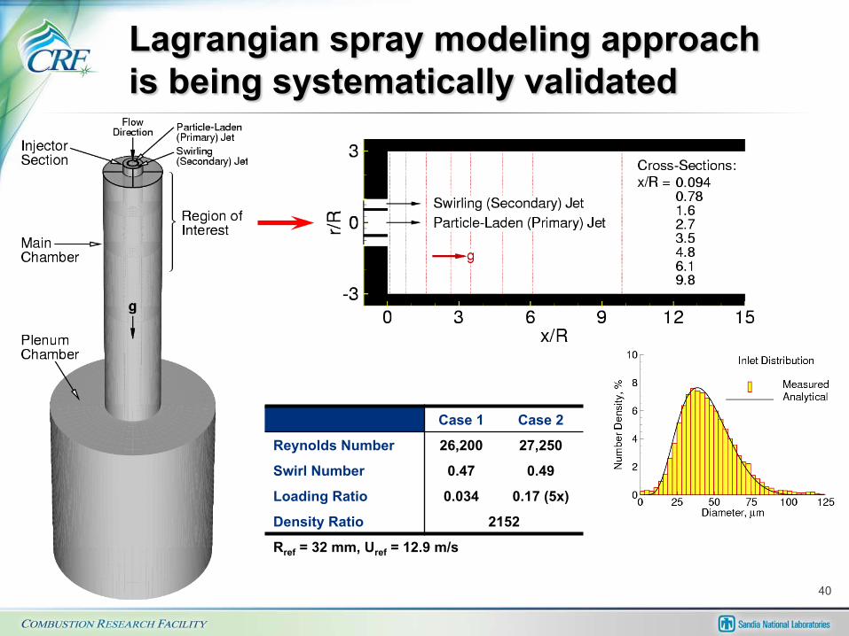
Case 1 Case 2
Reynolds Number 26,200 27,250
Swirl Number 0.47 0.49
Loading Ratio 0.034 0.17 (5x)
Density Ratio 2152
Rref = 32 mm, Uref = 12.9 m/s
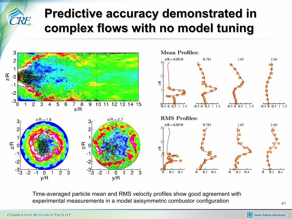
41
Time-averaged particle mean and RMS velocity profiles show good agreement with experimental measurements in a model axisymmetric combustor configuration

End
45