large diameter gran diámetro grand diamètre große durchmesser … · · 2017-08-15gran...
TRANSCRIPT

P I O N E E R S I N P I P E S O L U T I O N S
Large DiameterGran DiámetroGrand DiamètreGroße Durchmesser Фитинги большого диаметра Grande DiametroFlange Adaptor • Adaptador de bridas • Adaptateur à bride • Flanschadapter • Фланцевый адаптер • Adattatore flangiato
INSTALLATION INSTRUCTIONS – GBINSTRUCCIONES DE INSTALACIÓN – ESPNOTICE DE MONTAGE – FR
MONTAGEANLEITUNG – DИНСТРУКЦИЯ ПО МОНТАЖУ – RUSISTRUZIONI PER L'INSTALLAZIONE – I
Equipment that you will require for installation:Equipo necesario para la instalación:Outils nécessaires pour l'installation du raccord grand diamètre:
Werkzeuge und Hilfsmittel für die Montage:Оборудование, которое вам потребуется для установки:Attrezzatura necessaria per l'installazione:
• Tape Measure • Cinta métrica • Règle graduée • Bandmaß • Рулетка
• Metro a nastro
• Rag / File • Trapo / Lima •Toile émeri / lime • Raspel / Feile
• Тряпка / напильник • Straccio/lima
• Approved Lubrication • Lubricante Aprobado • Lubrifiant approuvé • Zugelassenes
Schmiermittel • Утвержденные смазочные материалы • Lubrificante approvato
• Torque Wrench • Llave dinamométrica • Clé dynamométrique • Drehmomentschlüssel
• динамометрический ключ • Chiave dinamometrica
• Deep Socket • Boca larga • Douille allongée • Bussola
• Глубокий присоединительный штепсель • Chiave a bussola
• Ratchet or Spanner • Trinquete o llave inglesa • Clé à cliquet ou clé à molette • Ratsche oder
Maulschlüssel • Торцовый накладной ключ или гаечный ключ • Cricchetto o chiave a forchetta

Large Diameter Flange AdaptorsThese fitting instructions apply to Viking Johnson Unfitted Flange Adaptors; i.e. the components, flange body, end ring, gasket, nuts and washers are supplied unassembled. These instructions cover both Straight Sleeve and 'S' Bore flange adaptors.
1. Examine the pipe ends and ensure they are round, smooth, free from bulges, dents and score marks and within the specified tolerances for that material. Weld beads must be ground flush, maintaining correct surface profile. Ensure that pipe ends are free from scale, rust, or any loose debris or other surface defects that may affect coupling performance. (Fig. 1)
2. Check grade of gasket is suitable for conveyed medium.
3. Dismantle the flange adaptor by removing end ring from studs and retain the nuts and washers (discard plastic stud protectors, if fitted). Note orientation of end ring relative to main body of adaptor and make temporary marks to ensure the same orientation of the components when they are assembled on the pipe.
4. Place the end ring over the pipe end, ensuring that the gasket chamber faces the mating flange. (Fig. 2)
5. Lubricate the gasket thoroughly with water quality approved pipe jointing lubricant and stretch it onto the pipe end, ensuring that the thicker or vertical end is towards the end ring. (Fig. 2)
6. Place the adaptor body onto the pipe end. (Fig. 2)
7. Align the pipe end with the mating flange, taking care that pipe end is concentric with the bore of the flange. (Fig. 3)
8. Adjust the setting gap between the pipe end and mating flange / 'S' bore flange adaptor as necessary (fig. 3, 4.1 & 4.2) – see 'Setting Gap Table'. If in doubt contact the Viking Johnson Technical Department.
Fig. 1
Fig. 4.1 Fig. 4.2
Setting GapSetting Gap
Straight Sleeve Flange Adaptors are supplied as shown in Fig. 4.1 and are able to slide fully onto the end of the pipe.
Sleeve LengthSleeve Length
'S' b
ore
flang
e
'S' bore Flange Adaptors are supplied as shown in Fig. 4.2 and are not able to slide fully onto the end of the pipe.
Fig. 2
Fig. 3
REV02
INSTA
LLATION
INSTR
UC
TION
S - English

9. Fit flange gasket (Viking Johnson recommend the use of an IBC Gasket) and bolt the adaptor body to the mating flange using standard flange bolting procedures. (Fig. 5)
10. Slide the gasket forward into the gasket chamber of the centre sleeve on the adaptor body (the end ring may assist in this operation). (Fig. 5)
11. Bring the end ring into position, locate the studs and fit the washers and nuts finger tight and recheck the setting gap.
12. Tighten diametrically opposed studs giving the nuts one or two turns at a time to draw up the end ring evenly (Fig. 6). The studs must be thoroughly tightened to the figures given in the 'Stud Torque Table' working around the flange adaptor as many times as necessary. On completion, the radial gap between pipe and end ring should be even all the way round. Rubber may be seen to extrude into the gap.
Stud Torque Table
BoltTorque
Ibf.ft Nm
M12 40 - 50 55 - 65
M16 70 - 90 95 - 120
Fig. 5
Fig. 6
Setting Gap Table
Pipe Diameter Range
Standard Sleeve Length
Straight Sleeve 'S' Bore
Recommended Max. Recommended Max.
from 355mm to 914mm 73mm 25mm 50mm 10mm 50mm
from 915mm to 1123mm 87mm 40mm 75mm 20mm 75mm
from 1124mm to 1820mm 87mm 40mm 75mm 20mm 75mm
Over 1820mm 125mm 55mm 114mm 25mm 114mm
NotesA. Other sleeve widths are available - contact Viking Johnson for further advice.B. Standard Viking Johnson Flange Adaptors do not prevent pipe pullout.
Adequate external restraint to the pipework is essential.C. When installing Viking Johnson Flange Adaptors on GRP and certain AC pipes
a reduced bolt torque is required- Consult Viking Johnson Technical Department for further advice.
REV02
INSTA
LLATION
INSTR
UC
TION
S - English

Adaptadores de brida de gran diámetroEstas instrucciones de instalación son aplicables a los adaptadores de brida no montados de Viking Johnson, es decir, los componentes, el cuerpo de la brida, el anillo extremo, la junta, las tuercas y las arandelas se suministran sueltos, sin montar. Estas instrucciones abarcan tanto los adaptadores de brida de manguito recto como los adaptadores de brida con diámetro interior en «S».
1. Examine los extremos de las tuberías y asegúrese de que son redondos y lisos, no tienen abolladuras, mellas ni ralladuras y están dentro de las tolerancias especificadas para ese material. Los rebordes de soldadura deben estar limados al ras, manteniendo el correcto perfil de la superficie. Asegúrese de que los extremos de las tuberías no tengan escamas, óxido, ni ningún tipo de residuo suelto o cualquier otro defecto de la superficie que pueda afectar a la precisión de la unión. (Fig. 1)
2. Compruebe la categoría de la junta para asegurarse de que sea apta para el medio transportado.
3. Desmonte el adaptador de brida retirando el anillo extremo de los espárragos, y conserve las tuercas y las arandelas (deseche los protectores de plástico de los espárragos, si es que los llevan puestos). Fíjese en la orientación del anillo extremo en relación con el cuerpo principal del adaptador y haga marcas temporales para asegurarse de que lo coloca con la misma orientación cuando lo vuelva a montar en la tubería.
4. Coloque el anillo extremo sobre el extremo de la tubería, asegurándose de que la cámara de la junta quede de cara a la brida de acoplamiento. (Fig. 2)
5. Lubrique generosamente la junta con el lubricante para juntas de tubos aprobado como apto para uso con agua, y estírela sobre el extremo de la tubería, asegurándose de que el extremo más grueso o vertical quede orientado hacia el anillo extremo. (Fig. 2)
6. Coloque el cuerpo del adaptador sobre el extremo de la tubería. (Fig. 2)
7. Alinee el extremo de la tubería con la brida de acoplamiento, teniendo cuidado de que dicho extremo y el diámetro interior de la brida queden concéntricos. (Fig. 3)
Fig. 1
Fig. 4.1 Fig. 4.2
Ajuste de separaciónAjuste de separación
Los adaptadores de brida de manguito recto se suministran como se muestra en la figura 4.1 y pueden deslizarse totalmente sobre el extremo de la tubería.
Largo del manguito
Largo del manguito
Brid
a co
n di
ámet
ro
inte
rior
en «
S»
Los adaptadores de brida con diámetro interior en «S» se suministran como muestra la figura 4.2 y no pueden deslizarse totalmente sobre el extremo de la tubería.
Fig. 2
Fig. 3
REV02
INSTR
UC
CIO
NES D
E IN
STALA
CIÓ
N - Español

8. Ajuste la separación entre el extremo de la tubería y el adaptador de brida de acoplamiento / brida con diámetro interior en «S» según sea necesario (fig. 3, 4.1 y 4.2). Consulte la tabla de ajustes de la separación. Si tiene cualquier duda, póngase en contacto con el departamento técnico de Viking Johnson.
9. Coloque la junta de la brida (Viking Johnson recomienda utilizar una junta IBC) y sujete el cuerpo del adaptador a la brida de acoplamiento con los pernos siguiendo los procedimientos estándar. (Fig. 5)
10. Deslice la junta hacia el interior de la cámara de junta del manguito central que lleva el cuerpo del adaptador (el anillo extremo puede ayudar en esta operación). (Fig. 5)
11. Coloque el anillo extremo en su posición, localice los espárragos y apriete con los dedos las arandelas y las tuercas; después vuelva a comprobar el ajuste de separación.
12. Apriete los espárragos diametralmente opuestos dando una o dos vueltas a cada tuerca antes de pasar a la siguiente; de esta forma fijará el anillo extremo uniformemente (Fig. 6). Los espárragos deben apretarse con fuerza, según las cifras indicadas en la tabla de pares de apriete para espárragos, haciendo círculos alrededor del adaptador de brida tantas veces como sea necesario. Cuando haya acabado, la separación radial entre la tubería y el anillo extremo debería ser la misma en todo el contorno. Es posible que se vea el caucho extruido dentro de la separación.
Fig. 5
Fig. 6
REV02
INSTR
UC
CIO
NES D
E IN
STALA
CIÓ
N - Español
Tabla de pares de apriete para espárragos
PernoPar de apriete
Ib. ft. Nm
M12 40 - 50 55 - 65
M16 70 - 90 95 - 120
Tabla de ajustes de separación
Gama de diámetros de tubería
Longitud de
manguito estándar
Manguito recto Diámetro interior en «S»
Recomendado Máx. Recomendado Máx.
de 355 mm a 914 mm 73 mm 25 mm 50 mm 10 mm 50 mm
de 915 mm a 1123 mm 87 mm 40 mm 75 mm 20 mm 75 mm
de 1124 mm a 1820 mm 87 mm 40 mm 75 mm 20 mm 75 mm
Más de 1820 mm 125 mm 55 mm 114 mm 25 mm 114 mm
NotasA. Hay disponibles otros anchos de manguito. Póngase en contacto con Viking Johnson para obtener más información.B. Los adaptadores de brida estándar de Viking Johnson no evitan que se salgan las tuberías.
Es imprescindible utilizar un método de contención exterior apropiado para las tuberías.C. Para instalar los adaptadores de brida de Viking Johnson en tuberías de plástico reforzado con fibra de vidrio (GRP)
y en algunas tuberías de asbesto-cemento (AC) hará falta un par de apriete menor. Consulte al departamento técnico de Viking Johnson para que le asesoren con más detalle.

Adaptateurs à bride grand diamètreCes instructions de montage s'appliquent aux adaptateurs à bride non montés de Viking Johnson (les composants, le corps de bride, la contre-bride, le joint et les écrous et les rondelles sont fournis non assemblés). Ces instructions concernent à la fois le manchon droit et les adaptateurs à brides à talon d'appui.
1. Examinez les extrémités des tuyaux et assurez-vous qu'elles sont arrondies, lisses, sans bosses, sans entailles, ni rayures, et dans les limites de tolérance spécifiées pour ce matériau. Les cordons de soudure doivent etre arrasés afin d'obtenir une surface lisse. Assurez-vous que les extrémités de tuyaux sont exemptes de dépôts calcaires, de rouille ou de tout débris libres ou autres défauts de surface pouvant affecter la performance des raccords. (Fig. 1)
2. Vérifiez que le grade du joint est adapté aux produits transportés.
3. Démontez l'adaptateur à bride en retirant la contre-bride des goujons, (ou boulons) et conservez les écrous et les rondelles (jetez les protections de goujons en plastique si elles sont montées). Notez l'orientation de la contre-bride par rapport au corps principal de l'adaptateur et faites des marques temporaires pour vous assurer de la même orientation des composants lorsqu'ils seront assemblés sur le tuyau.
4. Placez la contre-bride sur l'extrémité du tuyau en vous assurant que la chambre de joint est tournée vers la bride de raccordement. (Fig. 2)
5. Lubrifiez le joint comme sur le schema fig 2 avec un lubrifiant approuvé par Viking Johnson et étirez-le sur l'extrémité du tuyau en vous assurant que l'extrémité verticale ou la plus épaisse s'oriente vers la contre-bride. (Fig. 2)
6. Placez le corps de l'adaptateur sur l'extrémité du tuyau. (Fig. 2)
7. Alignez l'extrémité du tuyau avec la bride de raccordement en vous assurant que l'extrémité du tuyau est concentrique par rapport à l'alésage de la bride. (Fig. 3)
8. Ajustez l'interstice de montage entre l'extrémité de tuyau et la bride de raccordement/l'adaptateur à brides à talon d'appui, selon les besoins (fig. 3, 4.1 et 4.2). Voir le tableau des interstices de montage. En cas de doute, contactez le département technique de Viking Johnson.
Fig. 1
Fig. 4.1 Fig. 4.2
Interstice de montageInterstice de montage
Les adaptateurs à brides à manchon droit sont livrés comme illustrés à la fig. 4.1 et sont à même de coulisser sur l'extrémité du tuyau.
Longueur du manchon
Longueur du manchon
Brid
e à
alés
age
en S
Les adaptateurs à bride à talon d'appui (S-Bore) sont livrés comme illustrés à la fig. 4.2 et sont à même de coulisser sur l'extrémité du tuyau.
Fig. 2
Fig. 3
REV02
NO
TICE D
E M
ON
TAG
E - Français
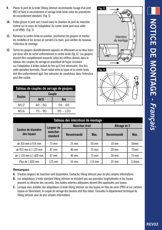
9. Placez le joint de la bride (Viking Johnson recommande l'usage d'un joint IBC) et faire le raccordement et serrage bride bride selon les procedures de raccordement standard. (Fig. 5)
10. Faites glisser le joint vers l'avant dans la chambre de joint du manchon central sur le corps de l'adaptateur (la contre-bride peut vous aider à cet effet). (Fig. 5)
11. Ramenez la contre-bride en position, positionnez les goujons et montez les rondelles et les écrous en serrant à la main, puis vérifiez de nouveau l'interstice de montage.
12. Serrez les goujons diamétralement opposés en effectuant un ou deux tours par écrou afin de serrer uniformément la contre-bride (fig. 6). Les goujons doivent être complètement resserrés selon les chiffres donnés dans le tableau des couples de serrage en procédant de façon circulaire sur l'adaptateur à brides autant de fois qu'il l'est nécessaire. Une fois cette opération terminée, l'écart radial entre le tuyau et la contre-bride doit être uniformément égal. Une extrusion de caoutchouc dans l'interstice peut être visible.
Fig. 5
Fig. 6
REV02
NO
TICE D
E M
ON
TAG
E - Français
Tableau de couples de serrage de goujons
BoulonCouple
Ibf.ft Nm
M12 40 - 50 55 - 65
M16 70 - 90 95 - 120
Tableau des interstices de montage
Section de diamètre des tuyaux
Largeur de manchon standard
Manchon droit Alésage en S
Recommandé Max. Recommandé Max.
de 355 mm à 914 mm 73 mm 25 mm 50 mm 10 mm 50mm
de 915 mm à 1 123 mm 87 mm 40 mm 75 mm 20 mm 75mm
de 1 124 mm à 1 820 mm 87 mm 40 mm 75 mm 20 mm 75 mm
Plus de 1 820 mm 125 mm 55 mm 114 mm 25 mm 114mm
RemarquesA. D'autres largeurs de manchon sont disponibles. Contactez Viking Johnson pour de plus amples informations.B. Les adaptateurs à bride standard Viking Johnson ne résistent pas aux poussées longitudinales et les tuyaux
peuvent se rétracter des raccords. Des butées externes adéquates doivent être appliquées aux tuyaux.C. Lorsque vous installez des adaptateurs à bride Viking Johnson sur des tuyaux en fibre de verre (PRV) et sur certains
tuyaux en fibrociment, le couple de serrage des boulons doit être réduit. Consultez le département technique de Viking Johnson pour de plus amples informations.

Flanschadapter mit großem DurchmesserDie vorliegende Montageanleitung betrifft Flanschadapter von Viking Johnson, deren Teile wie Pinole/Flanschgehäuse, Abschlussring, Dichtung, Schrauben und Unterlegscheiben nicht vormontiert geliefert werden. Diese Anleitung betrifft sowohl Flanschadapter mit gerader Form als auch Flanschadapter mit „S“-Bohrung.
1. Kontrollieren Sie die Rohrenden und überzeugen Sie sich, dass diese rund und glatt sind und weder Wölbungen noch Riefen aufweisen sowie im für dieses Materials ausgewiesenen Toleranzbereich liegen. Schweißnähte müssen glatt geschliffen und das Oberflächenprofil intakt sein. Stellen Sie sicher, dass sich an den Rohrenden kein Zunder, Rost oder lose Ablagerungen befinden bzw. sonstige Beschädigungen, die sich auf die Funktion der Kupplung auswirken könnten. (Abb. 1)
2. Überprüfen Sie die Eignung der Dichtung für das Fördermedium.
3. Entfernen Sie zur Demontage des Flanschadapters den Abschlussring von dem Haltebolzen und bewahren Sie die Muttern und Unterlegscheiben auf (entsorgen Sie Schutzkappen aus Plastik, soweit solche vorhanden sind). Merken Sie sich die Ausrichtung des Abschlussrings zum Hauptgehäuse des Adapters und kennzeichnen Sie den Sitz der Teile mit einer temporären Markierung, um diese später wieder in der gleichen Reihenfolge auf der Rohrleitung montieren zu können.
4. Setzen Sie den Abschlussring auf das Rohrende und achten Sie darauf, dass die Dichtungskammer zum Gegenflansch ausgerichtet ist. (Abb. 2)
5. Schmieren Sie die Dichtung gründlich mit einem Schmiermittel für Rohrverbindungen ein, das die Wasserqualität erwiesenermaßen nicht beeinträchtigt, und ziehen Sie die Dichtung auf das Rohrende. Achten Sie dabei darauf, dass das dickere bzw. vertikale Ende zum Abschlussring hin ausgerichtet ist. (Abb. 2)
6. Schieben Sie das Adaptergehäuse auf das Rohrende. (Abb. 2)
7. Richten Sie das Rohrende zum Gegenflansch aus, und stellen Sie sicher, dass es mittig zur Flanschöffnung sitzt. (Abb. 3)
Fig. 1
Fig. 4.1 Fig. 4.2
SpalteinstellungSpalteinstellung
Flanschadapter mit gerader Form, wie in Abb. 4.1 gezeigt, werden mitgeliefert und können vollständig auf das Rohrende geschoben werden.
Länge der Pinole
Länge der Pinole
Flan
sch
mit
„S“-
Boh
rung
Flanschadapter mit „S“-Bohrung, wie in Abb. 4.2 gezeigt, werden mitgeliefert und können nicht vollständig auf das Rohrende geschoben werden.
Fig. 2
Fig. 3
REV02
MO
NTA
GEA
NLE
ITUN
G - D
eutsch

8. Passen Sie den Spalt zwischen dem Rohrende und dem Gegenflansch/Flanschadapter mit "S"-Bohrung entsprechend an (Abb. 3) - siehe „Tabelle für Spalteinstellung“. Wenn Sie sich unsicher sind, setzen Sie sich mit der Fachabteilung von Viking Johnson in Verbindung.
9. Setzen Sie die Flanschdichtung ein (Viking Johnson empfiehlt IBC Dichtungen), und schrauben Sie das Adaptergehäuse an den Gegenflansch unter Beachtung der für Verschraubungen üblichen Vorgehensweise. (Abb. 5)
10. Schieben Sie die Dichtung in die Dichtungskammer der Pinole des Adaptergehäuses (nehmen Sie hierzu den Abschlussring zu Hilfe). (Abb. 5)
11. Positionieren Sie den Abschlussring, setzen Sie die Schrauben ein und drehen Sie die Muttern und Unterlegscheiben mit der Hand fest, bevor Sie die Spalteinstellung nochmals überprüfen.
12. Ziehen Sie die diametral entgegengesetzten Schrauben mit jeweils ein oder zwei Drehungen der Muttern fest, um den Abschlussring gleichmäßig anzuziehen (Abb. 6). Die Schrauben müssen sorgfältig unter Beachtung der in der „Drehmoment-Tabelle“ genannten Werte angezogen werden. Wiederholen Sie diesen Vorgang, bis der Flanschadapter entsprechend fest sitzt. Der Spalt zwischen dem Rohr und dem Abschlussring muss rundum gleichmäßig verlaufen. Die in den Spalt gedrückte Dichtung ist evtl. sichtbar.
Fig. 5
Fig. 6
REV02
MO
NTA
GEA
NLE
ITUN
G - D
eutsch
Drehmoment-Tabelle
SchraubenbolzenDrehmoment
Ibf.ft Nm
M12 40 - 50 55 - 65
M16 70 - 90 95 - 120
Tabelle für Spalteinstellung
Lieferbare Rohrdurchmesser
Stan
dard
läng
e de
r Pin
ole Gerade Form „S“-Bohrung
Empfohlen Max. Empfohlen Max.
von 355 mm bis 914 mm 73 mm 25 mm 50 mm 10 mm 50 mm
von 915 mm bis 1123 mm 87 mm 40 mm 75 mm 20 mm 75 mm
von 1124 mm bis 1820 mm 87 mm 40 mm 75 mm 20 mm 75 mm
über 1820 mm 125 mm 55 mm 114 mm 25 mm 114 mm
HinweisA. Pinolen in weiteren Breiten erhältlich. Für weitere Informationen wenden Sie sich bitte an Viking Johnson.B. Standard-Flanschadaptoren von Viking Johnson verhindern nicht den möglichen Auszug von Rohren.
Eine angemessene externe Absicherung der betreffenden Rohre ist daher unerlässlich.C. Bei der Anbringung von Viking Johnson Flanschadaptoren an GFK-Rohren und an bestimmten AZ-Rohren ist ein
geringerer Anzugsmoment erforderlich. Setzen Sie sich für weitere Informationen mit der Fachabteilung von Viking Johnson in Verbindung.

Фланцевые адаптеры большого диаметраДанные указания по монтажу относятся к собираемым фланцевым адаптерам Viking Johnson, т. е. отдельные части, корпус фланца, прижимное кольцо, уплотнительная манжета, гайки и шайбы поставляются в разобранном виде. Данные указания по монтажу относятся как к проходным, так и к фланцевым адаптерам с плоским фланцем S.
1. Осмотрите концы труб и убедитесь, что они круглые, гладкие, не имеют выступов, вмятин и сколов и удовлетворяют указанным допускам для данного материала. Наплавленный металл необходимо сошлифовать заподлицо, чтобы обеспечить правильный профиль поверхности. Концы труб должны быть очищены от отложений, ржавчины, загрязнений или иных дефектов поверхности, которые могут повлиять на работу фланцевого адаптера. (Рис. 1)
2. Материал манжеты должен соответствовать транспортируемой среде.
3. Демонтируйте фланцевый адаптер, сняв прижимное кольцо со шпилек, и сохраните гайки и шайбы (утилизируйте пластиковые колпачки шпилек, если они установлены). Обратите внимание на расположение прижимного кольца относительно корпуса фланцевого адаптера и сделайте временные отметки, чтобы обеспечить такую же ориентацию компонентов при установке на трубу.
4. Установите прижимное кольцо на конце трубы, так чтобы полость уплотнительной манжеты располагалась напротив ответного фланца. (Рис. 2)
5. Тщательно смажьте уплотнительную манжету смазкой для соединения труб, одобренной для применения в контакте с водой, и натяните ее на конец трубы, чтобы более толстая или вертикальная сторона была обращена к прижимному кольцу. (Рис. 2)
6. Установите корпус фланцевого адаптера на конец трубы. (Рис. 2)
Рис. 1
Рис. 4.1 Рис. 4.2
Рис. 2
Рис. 3
REV02
ИН
СТ
РУ
КЦ
ИЯ
ПО
МО
НТА
ЖУ
- РУССКИЙ
Посадочный зазорПосадочный зазор
Прямые фланцевые адаптеры поставляются, как показано на рис. 4.1, и могут быть полностью надеты на конец трубы.
Длина переходного патрубка
Длина переходного патрубка
Фла
нцев
ый
адап
тер
S
Фланцевые адаптеры с плоским фланцем S поставляются, как показано на рис. 4.2, и не могут быть полностью надеты на конец трубы.

7. Совместите конец трубы с ответным фланцем, так чтобы конец трубы был отцентрирован относительно фланца. (Рис. 3)
8. Отрегулируйте посадочный зазор между концом трубы и ответным фланцем / фланцевым адаптером с плоским фланцем S (рис. 3, 4.1 и 4.2) – см. "Таблицу значений посадочного зазора". При возникновении сомнений обратитесь в технический отдел компании Viking Johnson.
9. Установите манжету фланца (компания Viking Johnson рекомендует использовать манжету IBC) и прикрепите болтами корпус фланцевого адаптера к ответному фланцу согласно стандартной процедуре затяжки болтов фланца. (Рис. 5)
10. Задвиньте манжету в полость манжеты центрального патрубка на корпусе фланцевого адаптера (для этого можно воспользоваться прижимным кольцом). (Рис. 5)
11. Установите прижимное кольцо в нужное положение, определите положение шпилек, установите шайбы и гайки, затяните их вручную и повторно проверьте посадочный зазор.
12. Затягивайте диаметрально противоположные шпильки, проворачивая гайки на один или два оборота за раз, чтобы равномерно затянуть прижимное кольцо (рис. 6). Шпильки необходимо тщательно затянуть на момент затяжки, указанный в "Таблице значений момента затяжки шпилек", проходя весь фланцевый адаптер столько раз, сколько необходимо. По окончании операции радиальный зазор между трубой и прижимным кольцом должен быть одинаковым по всей окружности. Резина может немного выдавливаться в зазор.
Рис. 5
Рис. 6
REV02
ИН
СТ
РУ
КЦ
ИЯ
ПО
МО
НТА
ЖУ
- РУССКИЙ
Таблица значений момента затяжки шпилек
БолтМомент затяжки
фунтов силы на фут Нм
M12 40–50 55–65
M16 70–90 95–120
Таблица значений посадочного зазора
Диапазон диаметров трубы
Стандартная длина
переходного патрубка
Прямой переходный патрубок
Фланцевый адаптер с плоским фланцем S
Рекомендуется Макс. Рекомендуется Макс.
от 355 мм до 914 мм 73 мм 25 мм 50 мм 10 мм 50 мм
от 915 мм до 1123 мм 87 мм 40 мм 75 мм 20 мм 75 мм
от 1124 мм до 1820 мм 87 мм 40 мм 75 мм 20 мм 75 мм
Свыше 1820 мм 125 мм 55 мм 114 мм 25 мм 114 мм
ЗамечанияA. Доступны переходные патрубки другого диаметра – обращайтесь за рекомендациями к
дилеру компании Viking Johnson.B. Стандартные фланцевые адаптеры Viking Johnson не предотвращают вытягивание трубы из
соединения. Необходимо обеспечить соответствующие узлы крепления трубопровода.C. При установке фланцевых адаптеров Viking Johnson на трубы из ПВХ и некоторых видов
асбоцемента необходимо использовать пониженный момент затяжки – для более подробной информации обратитесь в технический отдел компании Viking Johnson.
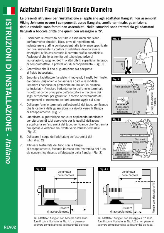
Adattatori Flangiati Di Grande DiametroLe presenti istruzioni per l'installazione si applicano agli adattatori flangiati non assemblati Viking Johnson; ovvero i componenti, corpo flangiato, anello terminale, guarnizione, dadi e rondelle sono forniti non assemblati. Nelle istruzioni sono trattati sia gli adattatori flangiati a boccola dritta che quelli con alesaggio a "S".
1. Esaminare le estremità del tubo e assicurarsi che siano perfettamente circolari, lisce, prive di rigonfiamenti, indentature e graffi e corrispondenti alle tolleranze specificate per quel materiale. I cordoni di saldatura devono essere smerigliati a filo assicurando il corretto profilo superficiale. Assicurarsi che le estremità del tubo siano prive di incrostazioni, ruggine, detriti o altri difetti superficiali in grado di compromettere le prestazioni di accoppiamento. (Fig. 1)
2. Controllare che il tipo di guarnizione sia adeguato al fluido trasportato.
3. Smontare l'adattatore flangiato rimuovendo l'anello terminale dai bulloni prigionieri e conservare i dadi e le rondelle (smaltire i cappucci di protezione dei bulloni in plastica, se installati). Annotare l'orientamento dell'anello terminale rispetto al corpo principale dell'adattatore e tracciare dei segni temporanei per garantire lo stesso orientamento dei componenti al momento del loro assemblaggio sul tubo.
4. Collocare l'anello terminale sull'estremità del tubo, verificando che la camera della guarnizione sia rivolta verso la flangia di accoppiamento. (Fig. 2)
5. Lubrificare la guarnizione con cura applicando lubrificante per giunzioni di tubi approvato per la qualità dell'acqua e applicarla sull'estremità del tubo, verificando che l'estremità più spessa o verticale sia rivolta verso l'anello terminale. (Fig. 2)
6. Collocare il corpo dell'adattatore sull'estremità del tubo. (Fig. 2)
7. Allineare l'estremità del tubo con la flangia di accoppiamento, facendo in modo che l'estremità del tubo sia concentrica rispetto all'alesaggio della flangia. (Fig. 3)
Fig. 1
Fig. 4.1 Fig. 4.2
Distanza di accoppiamento
Distanza di accoppiamento
Gli adattatori flangiati con boccola dritta sono forniti come illustrato in Fig. 4.1 e possono scorrere completamente sull'estremità del tubo.
Lunghezza della boccola
Lunghezza della boccola
Flan
gia
con
ales
aggi
o a
"S"
Gli adattatori flangiati con alesaggio a "S" sono forniti come illustrato in Fig. 4.2 e non possono scorrere completamente sull'estremità del tubo.
Fig. 2
Fig. 3
REV02
ISTRU
ZION
I DI IN
STALLA
ZION
E - Italiano

8. Regolare secondo necessità la distanza di accoppiamento tra l'estremità del tubo e l'adattatore flangiato di accoppiamento / con alesaggio a 'S' (fig. 3, 4.1 e 4.2) – vedere la "Tabella della distanza di accoppiamento". In caso di dubbi contattare il reparto tecnico Viking Johnson.
9. Installare la guarnizione della flangia e imbullonare il corpo dell'adattatore alla flangia di accoppiamento seguendo le procedure standard di fissaggio delle flange. (Fig. 5)
10. Far scorrere la guarnizione in avanti nella relativa camera della boccola centrale sul corpo dell'adattatore (l'anello terminale potrebbe agevolare questa operazione). (Fig. 5)
11. Portare l'anello terminale in posizione, collocare i bulloni prigionieri e installare le rondelle e i dadi serrandoli a mano e ricontrollare la distanza di accoppiamento.
12. Serrare i bulloni prigionieri con una sequenza diametralmente opposta avvitando i dadi di uno o due giri per volta per tirare l’anello terminale in modo uniforme. (Fig. 6). I bulloni prigionieri devono essere serrati completamente alle quote specificate nella "Tabella delle coppie di serraggio dei bulloni prigionieri", lavorando in sequenza circolare attorno all'adattatore flangiato per quante volte è necessario. Al termine dell'operazione, lo spazio radiale tra il tubo e l'anello terminale deve essere uniforme per l'intera circonferenza. La gomma potrebbe essere estrusa all'interno dello spazio.
Tabella delle coppie di serraggio dei bulloni prigionieri
BulloneCoppia di serraggio
Ibf.ft Nm
M12 40 - 50 55 - 65
M16 70 - 90 95 - 120
Fig. 5
Fig. 6
Tabella della distanza di accoppiamento
Gamma di diametri dei tubi
Lung
hezz
a de
lla b
occo
la
stan
dard
Boccola dritta Alesaggio a "S"
Consigliato Max. Consigliato Max.
Da 355mm a 914mm 73mm 25mm 50mm 10mm 50mm
Da 915mm a 1123mm 87mm 40mm 75mm 20mm 75mm
Da 1124mm a 1820mm 87mm 40mm 75mm 20mm 75mm
Misure superiori a 1820mm 125mm 55mm 114mm 25mm 114mm
NoteA. Sono disponibili boccole di altre larghezze, contattare Viking Johnson per ulteriori
informazioni.
B. Gli adattatori flangiati standard Viking Johnson non prevengono il distacco del tubo. È essenziale un dispositivo esterno adeguato al tubo.
C. Quando gli adattatori flangiati Viking Johnson vengono installati su tubi GRP e alcuni tubi AC, è necessario applicare una coppia di serraggio ridotta. Per ulteriori informazioni consultare il reparto tecnico Viking Johnson.
REV02
ISTRU
ZION
I DI IN
STALLA
ZION
E - Italiano

Notes:

Notes:

P I O N E E R S I N P I P E S O L U T I O N S
www.cranebsu.com
46-48 WILBURY WAY HITCHIN, HERTFORDSHIRE SG4 0UD. UK
TELEPHONE: +44 (0)1462 443322 FAX: +44 (0)1462 443311 EMAIL: [email protected]
DR
90
16
_28
_03
_20
17
Every effort has been made to ensure that the information contained in this publication is accurate at the time of publishing. Crane Ltd assumes no responsibility or liability for typographical errors or omissions or for any misinterpretation of the information within the publication and reserves the right to change without notice.
Se han extremado las precauciones para asegurar que la información contenida en este catálogo sea exacta en el momento de su publicación. Crane Ltd no acepta ninguna responsabilidad por errores tipográficos, omisiones o cualquier interpretación errónea de la información contenida en la publicación y se reserva el derecho de cambiarla sin previo aviso.
Toutes les précautions ont été prises pour vérifier l'exactitude des informations figurant aux présentes au moment de la publication. Crane Ltd n'accepte aucune responsabilité ni obligation relatives à des erreurs typographiques ou omissions ou à une interprétation erronée des informations figurant dans la publication et se réserve le droit de la modifier sans préavis.
Es wurden alle erforderlichen Massnahmen getroffen, um zu gewährleisten, dass zum Zeitpunkt der Herausgabe alle Informationen in dieser Publikation akurat und zutreffend sind. Crane LTD übernimmt keine Verantwortung oder Haftung für typografische Fehler, Auslassungen oder für etwaige Fehlinterpretationen innerhalb dieser Publikation und behält sich das Recht vor, Aenderungen jederzeit und ohne vorherige Ankündigung vorzunehmen.
Все наши усилия были направлены на то, чтобы информация, содержащаяся в настоящей публикации, являлась точной на момент ее издания. “Crane Ltd” не несет ответственности за типографские ошибки или упущения в виде неправильного толкования информации в публикации, и оставляет за собой право вносить любые изменения без предварительного уведомления.
È stato applicato il massimo impegno per garantire che le informazioni contenute nel presente documento siano accurate al momento della pubblicazione. Crane Ltd declina ogni responsabilità per eventuali omissioni o errori tipografici o qualsivoglia interpretazione errata delle informazioni contenute nella pubblicazione e si riserva il diritto di modifica senza preavviso.
To visit our Video Library go to: Para visitar nuestra videoteca consulte: Pour visiter notre bibliothèque vidéos se rendre à: Besuch unserer Videothek über: Чтобы войти в нашу Видеотеку воспользуйтесь ссылкой: Per visitare la libreria video accedere a: http://www.youtube.com/user/CraneBSU
ISO 14001 • EMS 51874 ISO 9001 • FM 00311