landscape architecture portfolio
DESCRIPTION
This portfolio chronicles my work at Temple University and in the first six months of a professional internship in landscape architecture.TRANSCRIPT
R a c h a e l G r i f f i t hl a n d s c a p e a r c h i t e c t u r e
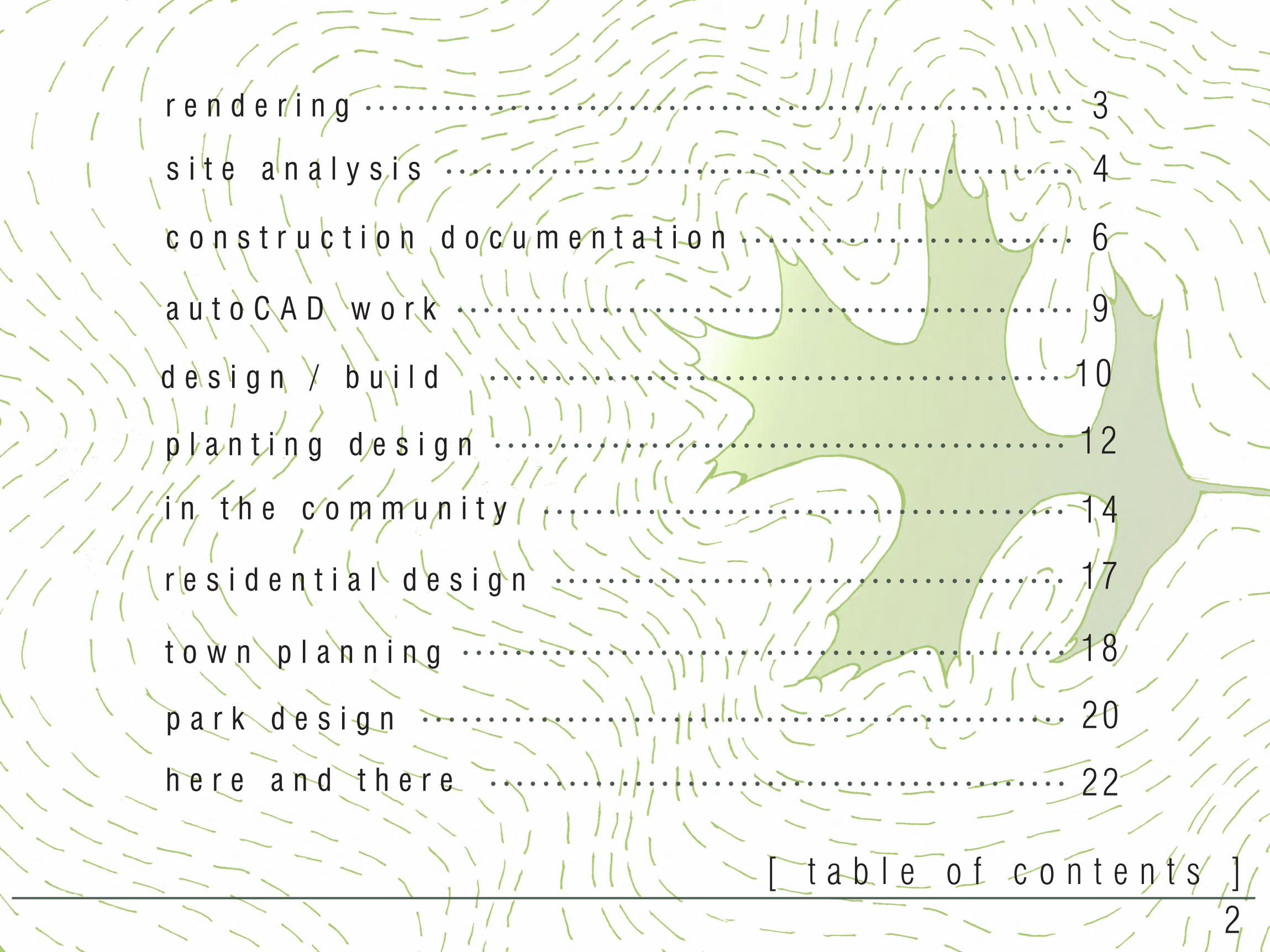
s i t e a n a l y s i s 4
c o n s t r u c t i o n d o c u m e n t a t i o n 6
p l a n t i n g d e s i g n 12
r e s i d e n t i a l d e s i g n 17
i n t h e c o m m u n i t y 14
t o w n p l a n n i n g 18
p a r k d e s i g n 20
h e r e a n d t h e r e 22
r e n d e r i n g 3
a u t o C A D w o r k 9
[ t a b l e o f c o n t e n t s ]2
d e s i g n / b u i l d 10
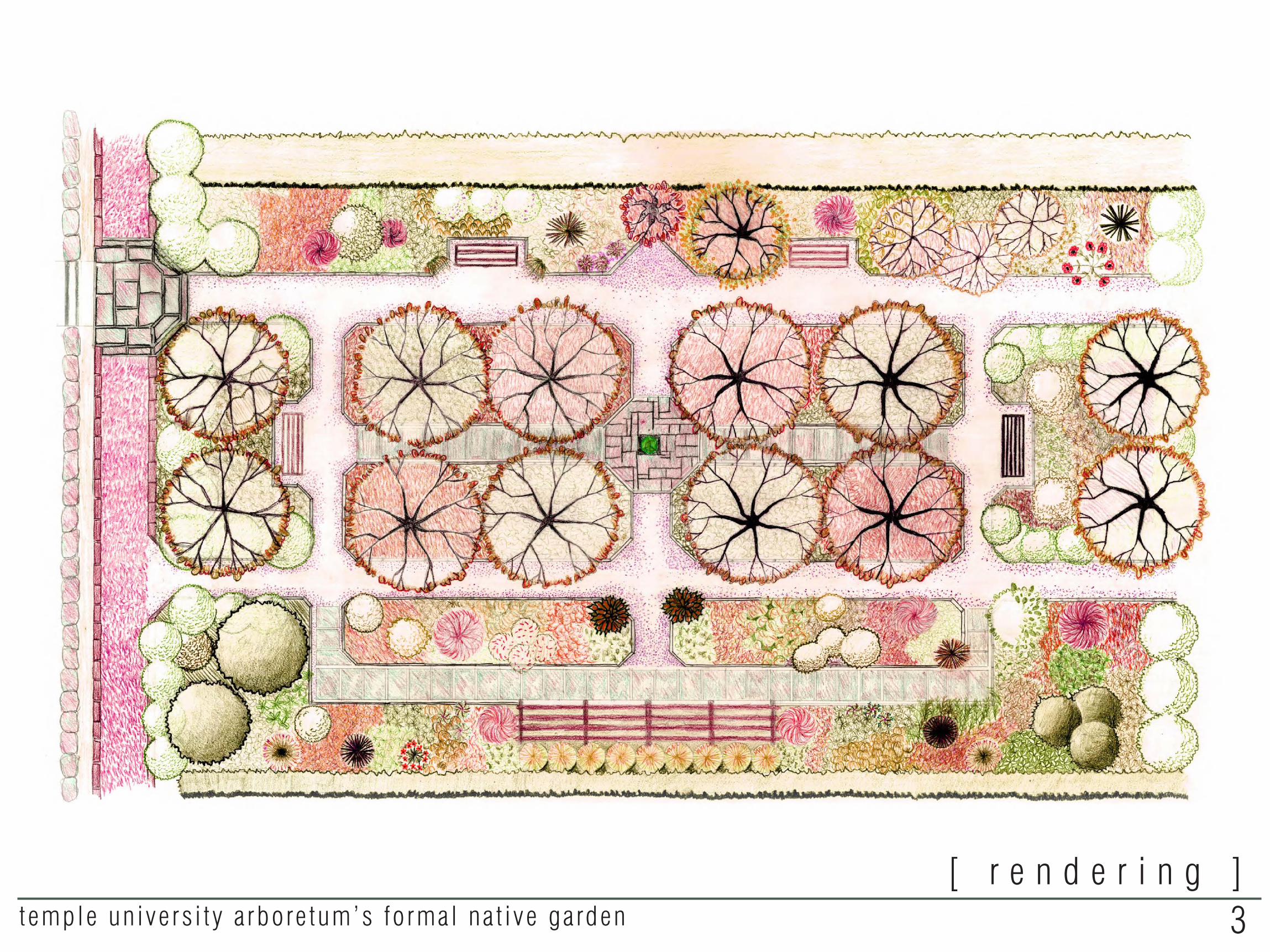
[ r e n d e r i n g ]3temple un ive rs i t y a rbore tum’s fo rmal na t i ve ga rden
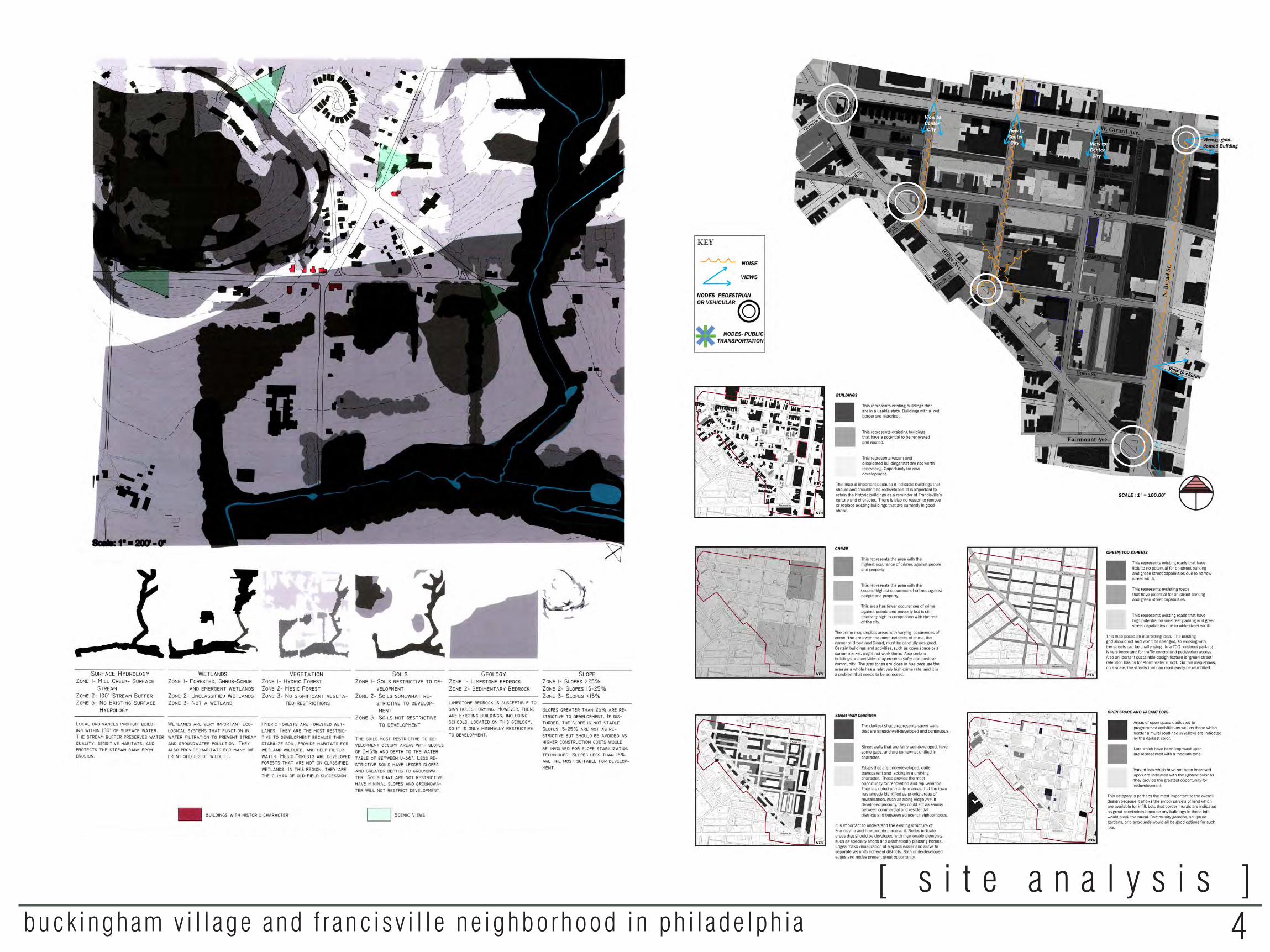
[ s i t e a n a l y s i s ]4buck ingham v i l l age and f ranc isv i l l e ne ighborhood in ph i lade lph ia

[ s i t e a n a l y s i s ]5prosek ne ighborhood v i t a l i za t ion , p rague , czech republ ic
c i rcu la t ion and con tex tp rob lems d iagram
landuse
soc ia l ana lys is
v isua l ana lys is
density comparison analysis
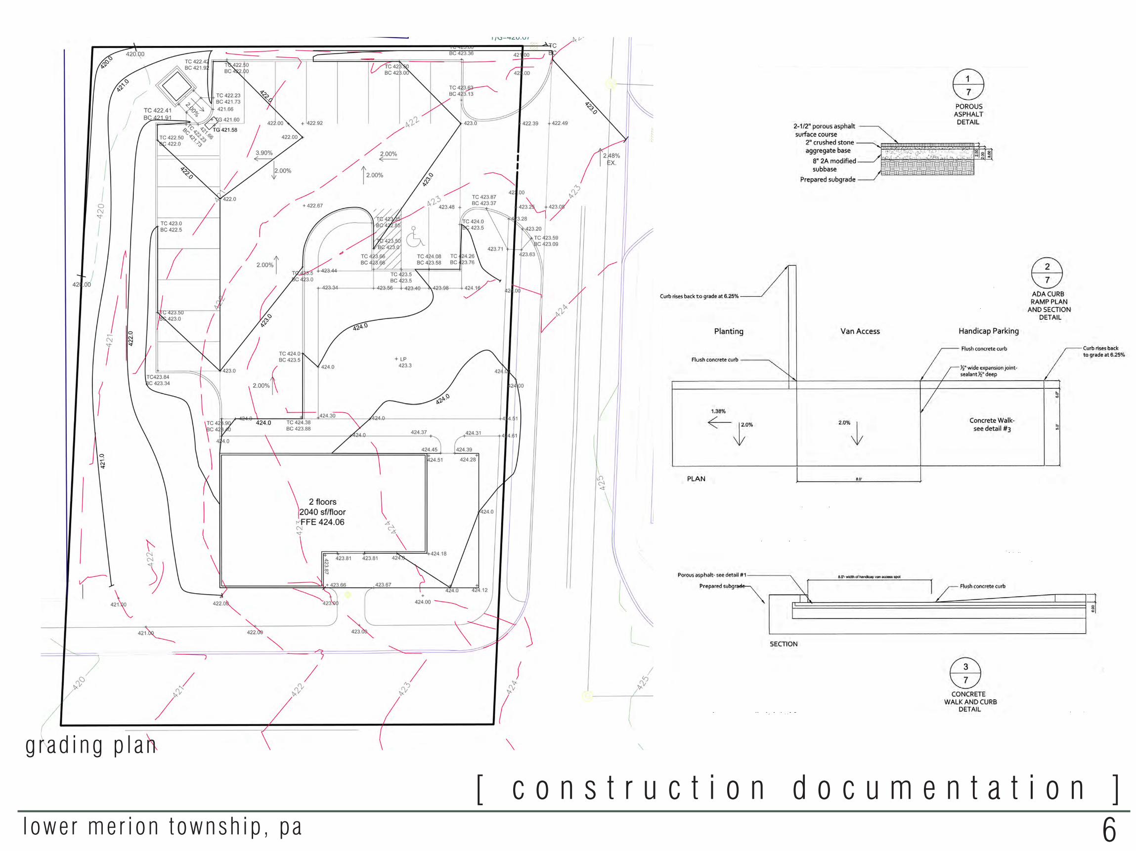
[ c o n s t r u c t i o n d o c u m e n t a t i o n ]6lower mer ion townsh ip , pa
grad ing p lan
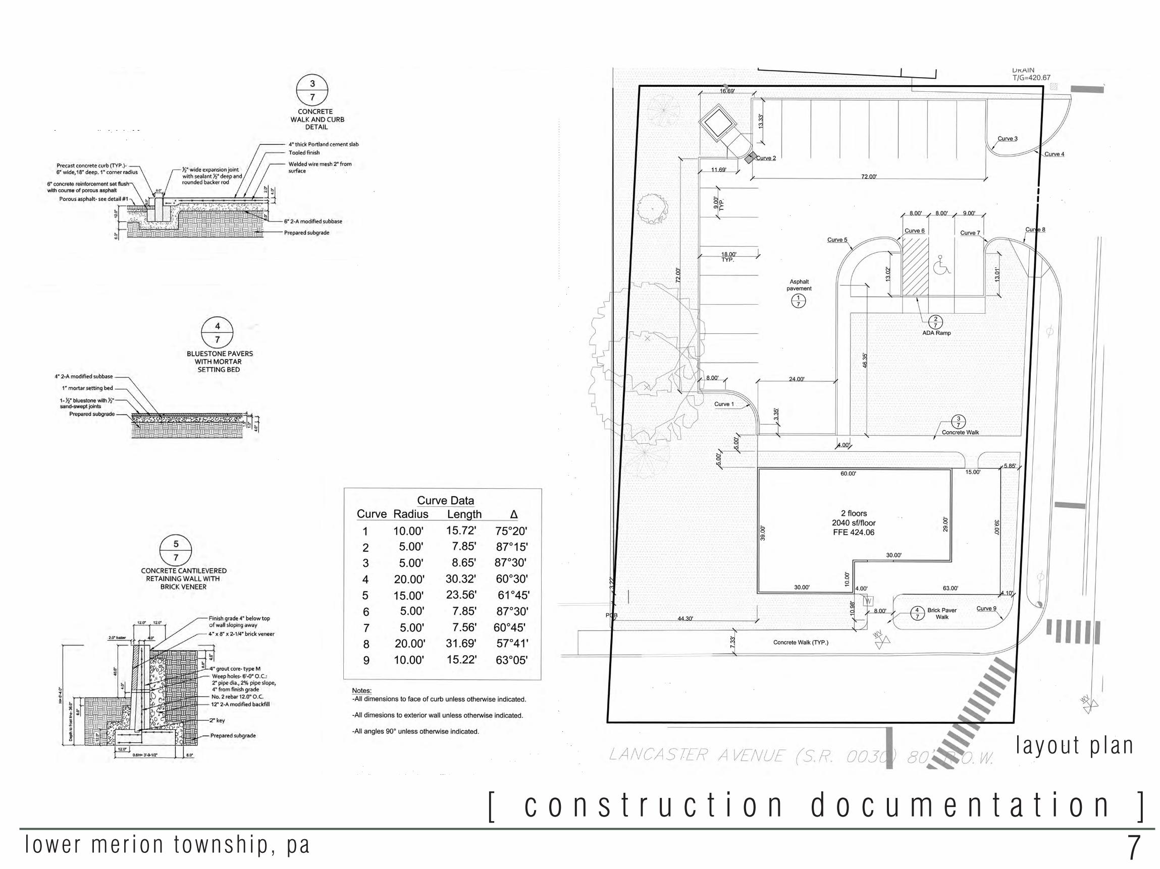
[ c o n s t r u c t i o n d o c u m e n t a t i o n ]7lower mer ion townsh ip , pa
layou t p lan
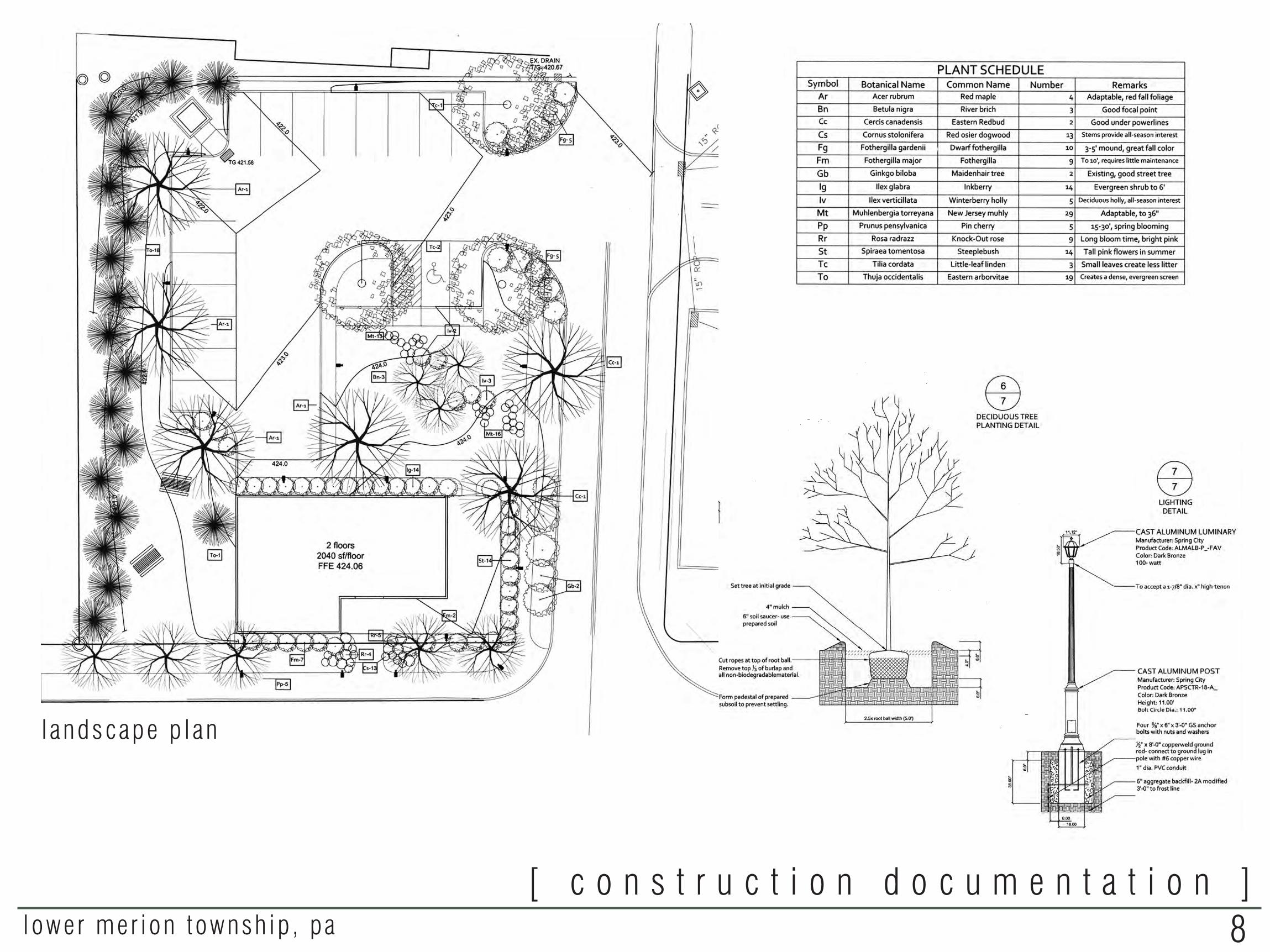
[ c o n s t r u c t i o n d o c u m e n t a t i o n ]8lower mer ion townsh ip , pa
landscape p lan
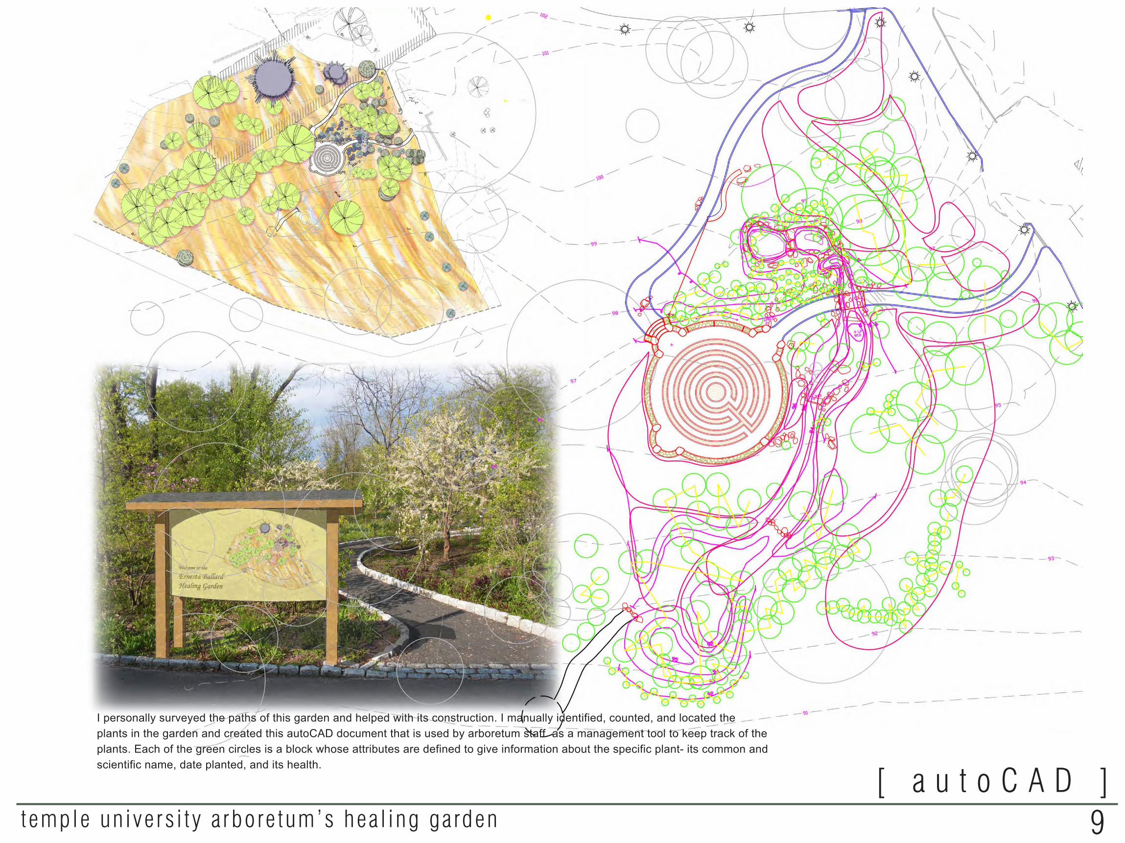
[ a u t o C A D ]9temple un ive rs i t y a rbore tum’s hea l ing ga rden
I personally surveyed the paths of this garden and helped with its construction. I manually identified, counted, and located the plants in the garden and created this autoCAD document that is used by arboretum staff as a management tool to keep track of the plants. Each of the green circles is a block whose attributes are defined to give information about the specific plant- its common and scientific name, date planted, and its health.
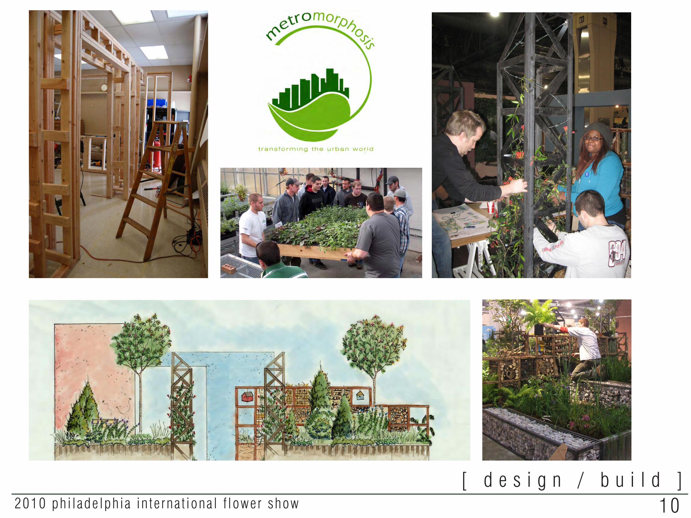
[ d e s i g n / b u i l d ]102010 ph i lade lph ia in te rna t iona l f lower show
PROJECT TITLE:
DESIGNED BY:
DRAWN BY:
SCALE:
DATE:
DRAWING NO:
Brochure Holders
Matthew CaucciRachael Griffith
Kevin MillerTrevor Sell
Rachael GriffithMatthew Caucci
Trevor Sell
1"=0'4"
March 22nd, 2010
SHEET 25 OF 25
L-9.1
met
rom
orp
ho
sis
20
10
PH
ILA
DEL
PHIA
INTE
RNA
TIO
NA
L FL
OW
ER S
HO
W
TEM
PLE
UNIV
ERSIT
Y AM
BLE
RD
EPARTM
ENT
OF
LAND
SC
APE
ARC
HIT
ECTU
RE
AND
HO
RTI
CULT
URE
58
0 M
EETI
NG
HO
USE
RO
AD
, AM
BLE
R P
A 1
90
02
JUNIO
R S
TUD
IO.
PRO
FESSO
RS B
ALD
EV L
AM
BA A
ND
MIC
HAEL
LO
FURNO
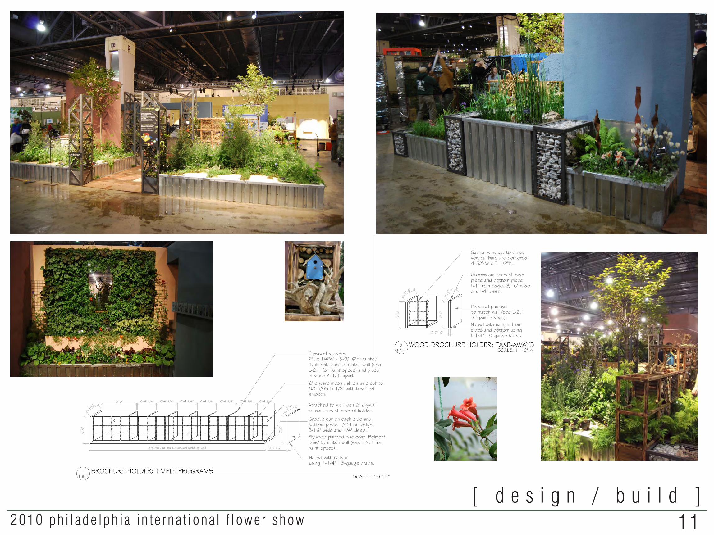
BROCHURE HOLDER:TEMPLE PROGRAMS
WOOD BROCHURE HOLDER: TAKE-AWAYS STEEL BROCHURE HOLDER: MAIN PAMPHLET STEEL BROCHURE HOLDER: TAKE-AWAYS3L-9.1
1L-9.1
2L-9.1
4L-9.1
SCALE: 1"=0'-4"0
'-6"
0'-5"
0'-2"
38-7/8", or not to exceed width of wall
0'-3"0'-8" 0'-4 1/4" 0'-4 1/4" 0'-4 1/4" 0'-4 1/4" 0'-4 1/4" 0'-4 1/4" 0'-4 1/4"
Attached to wall with 2" drywallscrew on each side of holder.
Groove cut on each side andbottom piece 1/4" from edge,3/16" wide and 1/4" deep.Plywood painted one coat "BelmontBlue" to match wall (see L-2.1 forpaint specs).
0'-6
"
Nailed with nailgunusing 1-1/4" 18-gauge brads.
2" square mesh gabion wire cut to38-5/8"x 5-1/2" with top filedsmooth.
Plywood dividers2"L x 1/4"W x 5-9/16"H painted"Belmont Blue" to match wall (seeL-2.1 for paint specs) and gluedin place 4-1/4" apart.
0'-6
"
0'-3"
Gabion wire cut to threevertical bars are centered-4-5/8"W x 5-1/2"H.
Groove cut on each sidepiece and bottom piece1/4" from edge, 3/16" wideand1/4" deep.
Plywood paintedto match wall (see L-2.1for paint specs).Nailed with nailgun fromsides and bottom using1-1/4" 18-gauge brads.
1'-4"
0'-6
"
EQUAL EQUAL EQUAL0'-2"
0'-2" 0'-2"
0'-6
"
0'-3"
0'-7/16"
0'-6
"
0'-3"
0'-7/16"
2" steel dividers tack welded tobottom piece in equal divisions.
2" square mesh 11 gaugegalvanized gabion wire, cut to15" and welded behind side pieces.
1/8" mild steel welded withcontinuous bead.Bottom piece 1/8" mild steel.
2" square mesh 11 gaugegalvanized gabion wire, cut to3" and welded behind side pieces.
1/8" mild steel welded withcontinuous bead.
Bottom piece 1/8" mild steel.
SCALE: 1"=0'-4" SCALE: 1"=0'-4"SCALE: 1"=0'-4"
1L-9.1
2L-9.1
2L-9.1
4L-9.1
3L-9.1
KEY PLAN SCALE: 1"=8'-0"
DESIGN INTENT
The brochure holders were sized to accommodateour brochures and were constructed of materialsfound elsewhere in the exhibit, such as gabion wire,steel and plywood. The rationale behind theirheight from the ground was to make them visible,accessible and in close proximity to the sign.
PROJECT TITLE:
DESIGNED BY:
DRAWN BY:
SCALE:
DATE:
DRAWING NO:
Brochure Holders
Matthew CaucciRachael Griffith
Kevin MillerTrevor Sell
Rachael GriffithMatthew Caucci
Trevor Sell
1"=0'4"
March 22nd, 2010
SHEET 25 OF 25
L-9.1
met
rom
orp
ho
sis
20
10
PH
ILA
DEL
PHIA
INTE
RNA
TIO
NA
L FL
OW
ER S
HO
W
TEM
PLE
UNIV
ERSIT
Y AM
BLE
RD
EPARTM
ENT
OF
LAND
SC
APE
ARC
HIT
ECTU
RE
AND
HO
RTI
CULT
URE
58
0 M
EETI
NG
HO
USE
RO
AD
, AM
BLE
R P
A 1
90
02
JUNIO
R S
TUD
IO.
PRO
FESSO
RS B
ALD
EV L
AM
BA A
ND
MIC
HAEL
LO
FURNO
BROCHURE HOLDER:TEMPLE PROGRAMS
WOOD BROCHURE HOLDER: TAKE-AWAYS STEEL BROCHURE HOLDER: MAIN PAMPHLET STEEL BROCHURE HOLDER: TAKE-AWAYS3L-9.1
1L-9.1
2L-9.1
4L-9.1
SCALE: 1"=0'-4"
0'-6
"
0'-5"
0'-2"
38-7/8", or not to exceed width of wall
0'-3"0'-8" 0'-4 1/4" 0'-4 1/4" 0'-4 1/4" 0'-4 1/4" 0'-4 1/4" 0'-4 1/4" 0'-4 1/4"
Attached to wall with 2" drywallscrew on each side of holder.
Groove cut on each side andbottom piece 1/4" from edge,3/16" wide and 1/4" deep.Plywood painted one coat "BelmontBlue" to match wall (see L-2.1 forpaint specs).
0'-6
"
Nailed with nailgunusing 1-1/4" 18-gauge brads.
2" square mesh gabion wire cut to38-5/8"x 5-1/2" with top filedsmooth.
Plywood dividers2"L x 1/4"W x 5-9/16"H painted"Belmont Blue" to match wall (seeL-2.1 for paint specs) and gluedin place 4-1/4" apart.
0'-6
"
0'-3"
Gabion wire cut to threevertical bars are centered-4-5/8"W x 5-1/2"H.
Groove cut on each sidepiece and bottom piece1/4" from edge, 3/16" wideand1/4" deep.
Plywood paintedto match wall (see L-2.1for paint specs).Nailed with nailgun fromsides and bottom using1-1/4" 18-gauge brads.
1'-4"
0'-6
"
EQUAL EQUAL EQUAL0'-2"
0'-2" 0'-2"
0'-6
"
0'-3"
0'-7/16"
0'-6
"
0'-3"
0'-7/16"
2" steel dividers tack welded tobottom piece in equal divisions.
2" square mesh 11 gaugegalvanized gabion wire, cut to15" and welded behind side pieces.
1/8" mild steel welded withcontinuous bead.Bottom piece 1/8" mild steel.
2" square mesh 11 gaugegalvanized gabion wire, cut to3" and welded behind side pieces.
1/8" mild steel welded withcontinuous bead.
Bottom piece 1/8" mild steel.
SCALE: 1"=0'-4" SCALE: 1"=0'-4"SCALE: 1"=0'-4"
1L-9.1
2L-9.1
2L-9.1
4L-9.1
3L-9.1
KEY PLAN SCALE: 1"=8'-0"
DESIGN INTENT
The brochure holders were sized to accommodateour brochures and were constructed of materialsfound elsewhere in the exhibit, such as gabion wire,steel and plywood. The rationale behind theirheight from the ground was to make them visible,accessible and in close proximity to the sign.
[ d e s i g n / b u i l d ]112010 ph i lade lph ia in te rna t iona l f lower show

[ p l a n t i n g d e s i g n ]12temple un ive rs i t y cen te r fo r sus ta inab le communi t ies
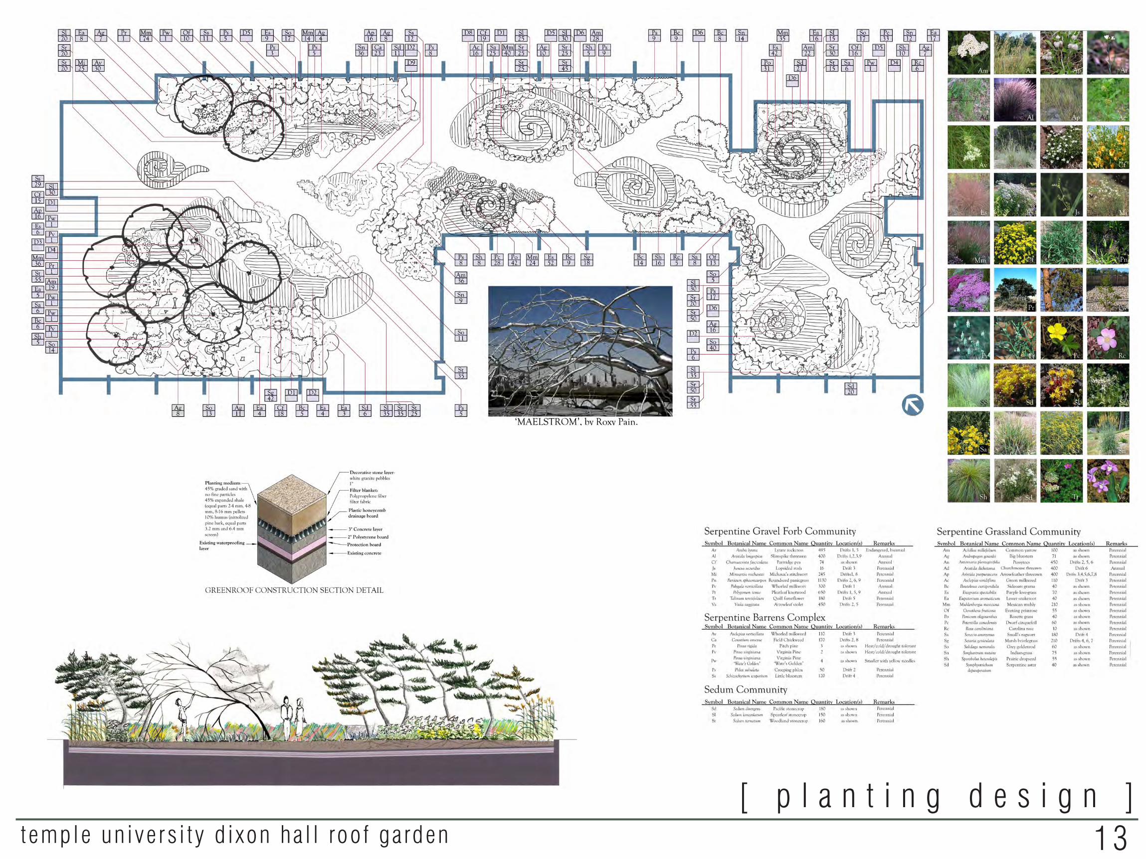
13temple un ive rs i t y d i xon ha l l roo f ga rden
[ p l a n t i n g d e s i g n ]

WILLIAM CRAMP ELEMENTARY GREEN SCHOOLYARD DESIGN
TEMPLE UNIVERSITY SCHOOL OF ENVIRONMENTAL DESIGNDEPARTMENT OF LANDSCAPE ARCHITECTURE
PROFESSORS STU APPEL, FASLA AND LOLLY TAI, FASLASPRING 2011 • RACHAEL GRIFFITH
•
Rain garden v iewing deck Serving as the terminus of the
axis created by paving pattern and drains, the rain garden is located at the southern-most point of the schoolyard. Drains which collect stormwater from the entire site flow underneath the wooden viewing deck and into the ponding area of the rain garden. Whimsical sculptures of aquatic amphibians are included in the design. The viewing deck, located adjacent to the outdoor classroom, provides an opportunity for students to learn about native plants, the water cycle, stormwater management, and aquatic ecosystems. A 3’ berm planted with highbush blueberry bushes (Vaccinium corymbosum) partially blocks the view outward into the surrounding neighborhood.
Outdoor c lassroomThe outdoor classroom is located farthest away
from the playground to decrease distraction. It is surrounded by a vegetated buffer for this same reason. Experimentation tables, stump seating, a large chalkboard, and a storage shed for garden tools are the site’s furnishings. A row of pawpaw trees (Asimina triloba) frames the space and provides a tasty fall treat. The outdoor classroom is flanked by forest and meadow habitats, a rain garden, and garden plots to maximize diverse environmental education opportunities.
Pick-up and drop-off p laza Looking west from Howard Street, this
area is currently the most popular point for children to be dropped off in the morning. A plaza paved with two colors of porous resin-bound aggregate is visually and physically separated from the adjacent parking lot. A 5’ vegetated strip with rain gardens between the sidewalk and the parking lot treats stormwater runoff from the sidewalk. Steps and a ramp were added to the existing raised platform which abuts the cafeteria entrance which can serve as an outdoor seating location for teachers. Pig-shaped cisterns collect overflow stormwater from the green roof. This water can be used to irrigate the garden plots.
v i e w o f r a i n g a r d e n v i e w i n g d e c k
WILLIAM CRAMP ELEMENTARY GREEN SCHOOLYARD DESIGN
TEMPLE UNIVERSITY SCHOOL OF ENVIRONMENTAL DESIGNDEPARTMENT OF LANDSCAPE ARCHITECTURE
PROFESSORS STU APPEL, FASLA AND LOLLY TAI, FASLASPRING 2011 • RACHAEL GRIFFITH
•
sidewalk forest habitat meadow habitat playground zone rain garden pick-up/drop-off plaza gym
section through the schoolyard
section through rain garden
the green schoolyardin context
ontario st.
mas
cher
st.
how
ard
st.
tioga st.
Left: This rain garden in the western pick-up and drop-off plaza collects stormwater from the plaza. To make it more accessible and interactive, it features raised stepping stones that children can hop across like frogs on lily pads. Its curvilinear edge is mimicked by benches of the same form which face the playground- a prime location for teachers to sit and watch the children from the shade.
Below: The schoolyard is arranged in layered zones to maximize its effectiveness. The uses that will be frequented most often or require the most care are located closest to the school such as the playground and garden plots. Those that require less tending or which will not be used every day such as the meadow and forest habitats are farther from the building. This layering is a basic principle of permaculture, the practice of using ecological and biological systems that complement each other to live more harmoniously with nature.
scale: 1”=1’-0”
scale: 1”=1’-0”
14wi l l i am cramp e lementa ry g reen schoolya rd des ign / ph i l ade lph ia , pa[ i n t h e c o m m u n i t y ]

WILLIAM CRAMP ELEMENTARY GREEN SCHOOLYARD DESIGN
TEMPLE UNIVERSITY SCHOOL OF ENVIRONMENTAL DESIGNDEPARTMENT OF LANDSCAPE ARCHITECTURE
PROFESSORS STU APPEL, FASLA AND LOLLY TAI, FASLASPRING 2011 • RACHAEL GRIFFITH
•
sidewalk forest habitat meadow habitat playground zone rain garden pick-up/drop-off plaza gym
section through the schoolyard
section through rain garden
the green schoolyardin context
ontario st.
mas
cher
st.
how
ard
st.
tioga st.
Left: This rain garden in the western pick-up and drop-off plaza collects stormwater from the plaza. To make it more accessible and interactive, it features raised stepping stones that children can hop across like frogs on lily pads. Its curvilinear edge is mimicked by benches of the same form which face the playground- a prime location for teachers to sit and watch the children from the shade.
Below: The schoolyard is arranged in layered zones to maximize its effectiveness. The uses that will be frequented most often or require the most care are located closest to the school such as the playground and garden plots. Those that require less tending or which will not be used every day such as the meadow and forest habitats are farther from the building. This layering is a basic principle of permaculture, the practice of using ecological and biological systems that complement each other to live more harmoniously with nature.
scale: 1”=1’-0”
scale: 1”=1’-0”
15wi l l i am cramp e lementa ry g reen schoolya rd des ign / ph i l ade lph ia , pa[ i n t h e c o m m u n i t y ]
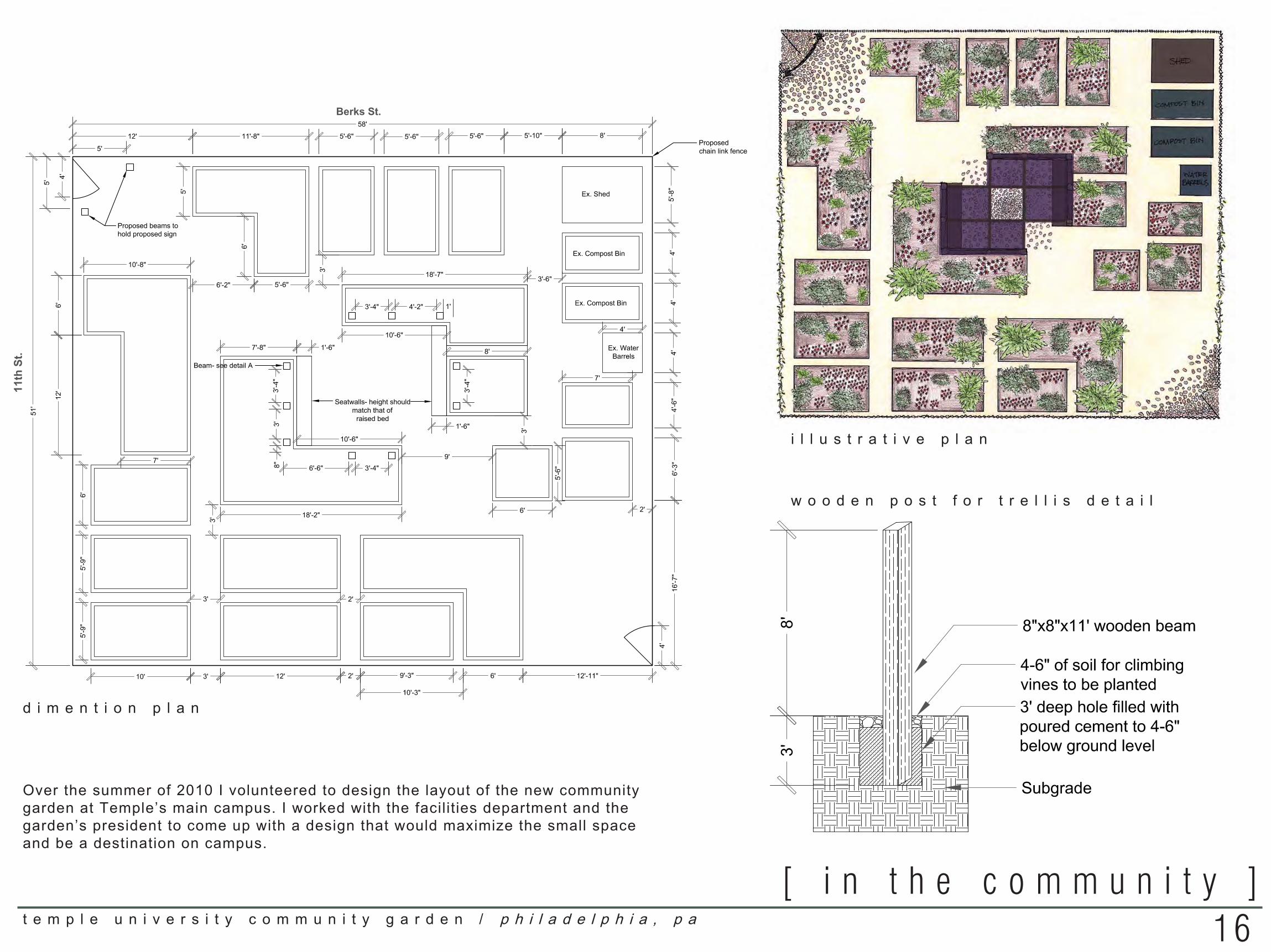
w o o d e n p o s t f o r t r e l l i s d e t a i l
16t e m p l e u n i v e r s i t y c o m m u n i t y g a r d e n / p h i l a d e l p h i a , p a
[ i n t h e c o m m u n i t y ]
Scale: 1"=4'-0"
0 1' 2' 4' 8' 12'
11th
St.
Berks St.
Notes:-Unless otherwise noted, paths between raised beds are 1'-0" wide-All proposed beds are to be constructed of the same materials they currently are constructed of.-Beams should be installed before raised beds so beds may be built around them (see detail A) and so machinery can fit into garden to dig holes-When raised beds are constructed around beams, beams should have 4" of space around them on all sides adjacent to raised bed walls to allowfor plants to climb up them on all sides-An approximately 4'-0" wide section of chain link fence shall be removed from the corners of fences indicated. The section of fence cut along 11thstreet shall be cut to approximately match the height of the black fence along Berks street (about 6' tall).-1" of ivory-colored pea gravel shall be spread on top of existing gravel-A 12'x12' square of 6"-9" smooth flat fieldstone of varying colors set into pea gravel will be installed in both corners of the garden where gates willbe located, as well as one central 12'x12' square. The stones shall be arranged so that in the corner squares the stones will be spaced veryclosely to one another (about 1
4" apart) at the corner of the space and will diffuse and become farther spaced apart toward the center of thegarden. The fieldstone in the central square will be most tightly spaced in the center of the square and diffuse outward in each direction (Seeillustrative plan).-Overhead plane of trellis is yet to be designed. Each beam for trellis is designed to be connected to a beam opposite it via an overheadhorizontally oriented beam, creating a square void in the center of the overhead plane.-Both fences parallel to 11th street to have vine crops grown up them in areas where walkway exceeds 1'-6". Plant height on fence should notdisrupt visibility into garden, so should not be allowed to climb higher up the fences than 4'-6" .
Materials:Total square footage of planters requiring soil = 1268
Total square footage of site= 2958Total square footage requiring 1" of pea gravel = 1690
Total board feet required= 658' (multiplied by number of boards thatneed to be stacked on top of each other to achieve desired height of
raised beds)- DOES NOT INCLUDE wood for seat walls, beams,shed, compost bins, and water barrel table
Total square footage to be laid with fieldstone= 432Total number of 8"x8" beams= 12
Detail A: Wooden post for trellis and entrance
C:\DOCUME~1\tua92958\LOCALS~1\Temp\Temporary Internet Files\Content.IE5\8STZ18KY\temple_uni_logo[1].pngTemple University Community Garden 11th and Berks St., Philadelphia
i l l u s t r a t i v e p l a n
d i m e n t i o n p l a n
Over the summer of 2010 I volunteered to design the layout of the new community garden at Temple’s main campus. I worked with the facilities department and the garden’s president to come up with a design that would maximize the small space and be a destination on campus.
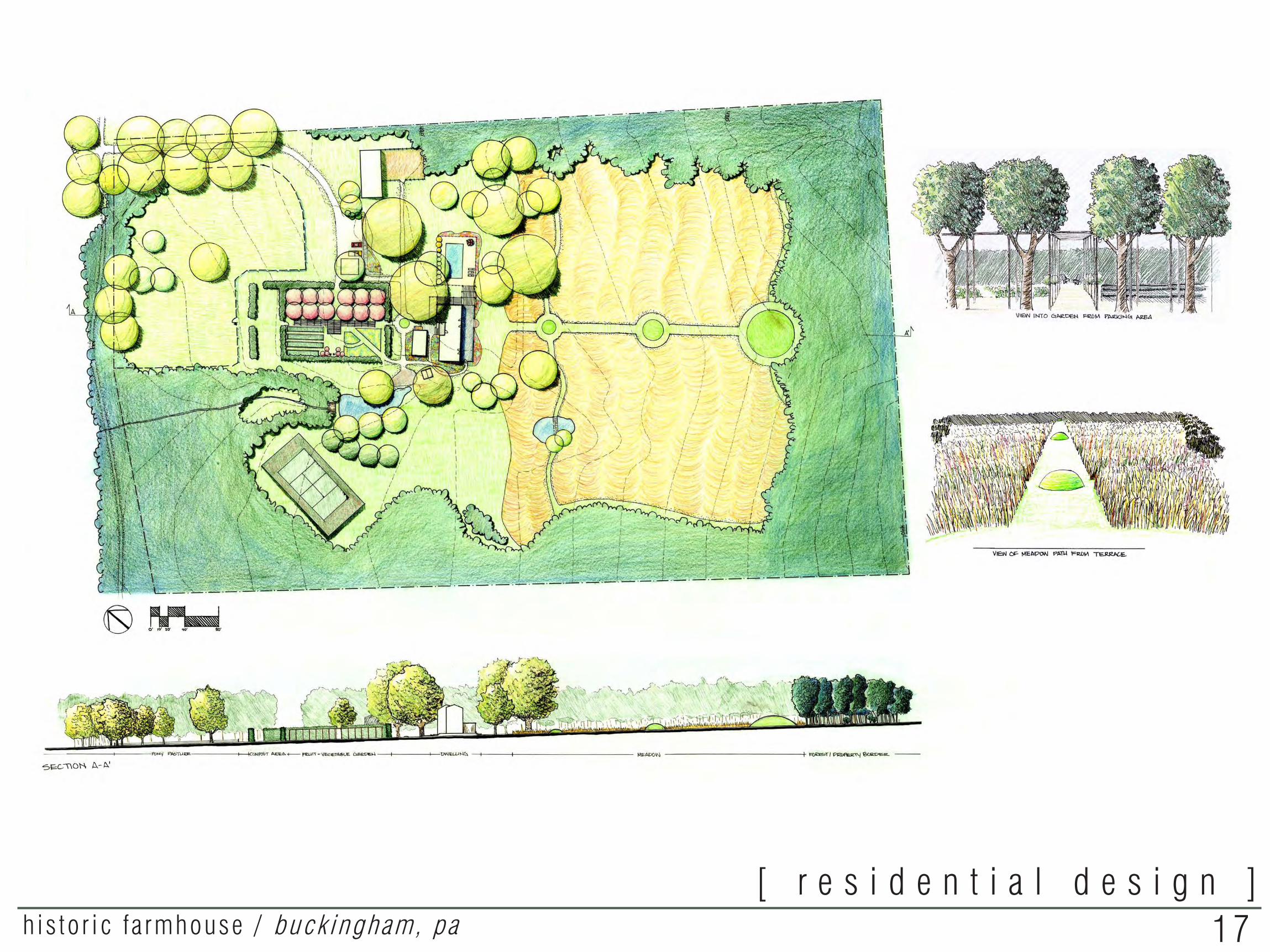
17his to r ic f a rmhouse / buck ingham, pa[ r e s i d e n t i a l d e s i g n ]
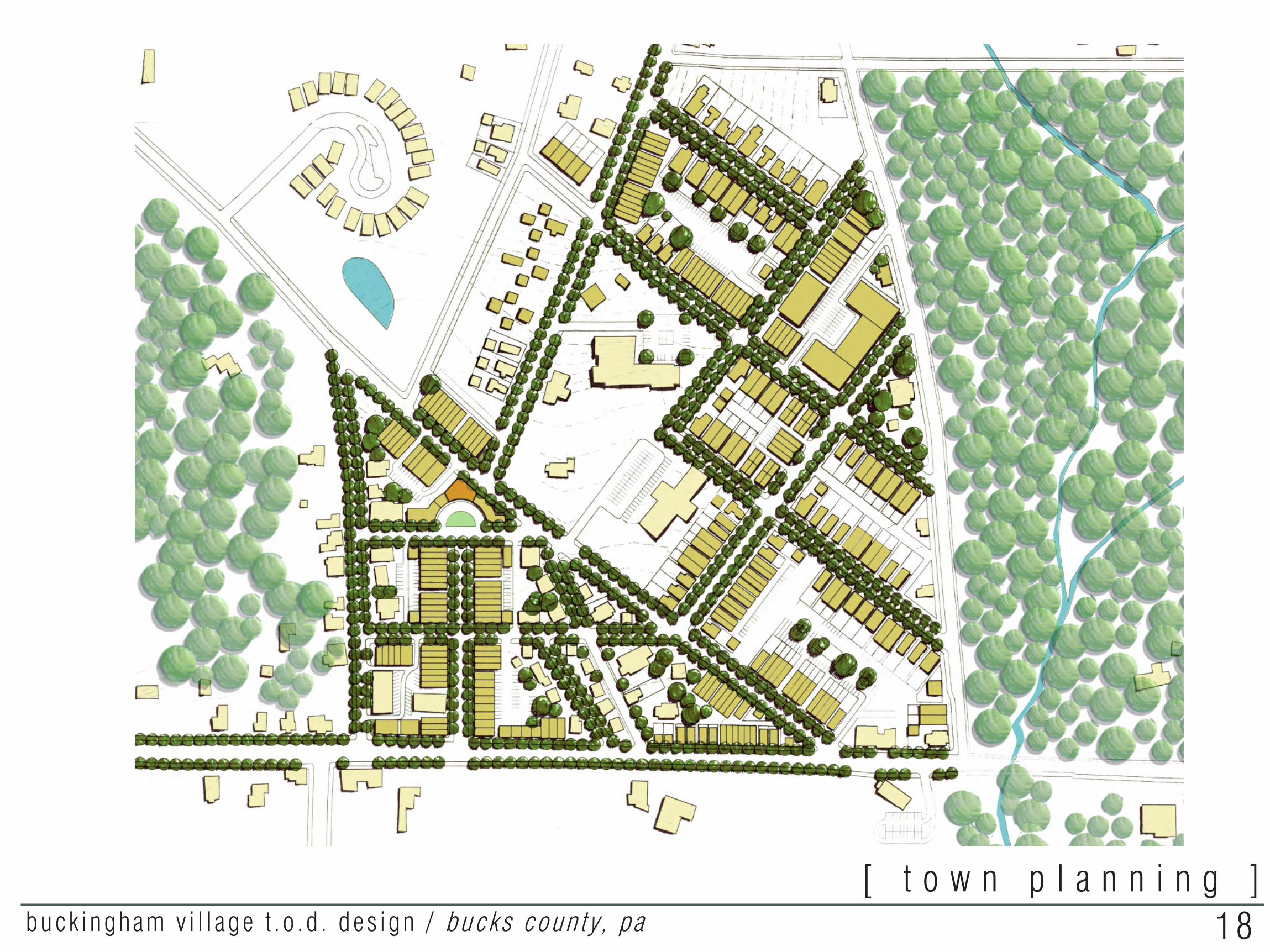
18buck ingham v i l l age t .o .d . des ign / bucks coun ty, pa[ t o w n p l a n n i n g ]
Design Intent:
• Create memorable streetscapes that employ comfortable building to building distances and sidewalk widths, street trees and prominent buildings as focal points
• Locate the dense community corridor at the epicenter of the village to create an imageable village center and to reduce sprawl into adjacent farmland
• Centrally-locate the transportation node where it will be easily accessible to all to encourage use
• Use the wetland area on the eastern portion of the site as a community gathering area and nature center to foster public awareness of the delicate condition of the surrounding environment
• Integrate housing types to encourage social diversity
Master Plan
Impervious Surface Coverage Pervious Surface
Conceptual Diagram
Regional Context
buckingham village master planRachael Griffith • La design studio II • Professor rob kuper • temple university • spring 2009
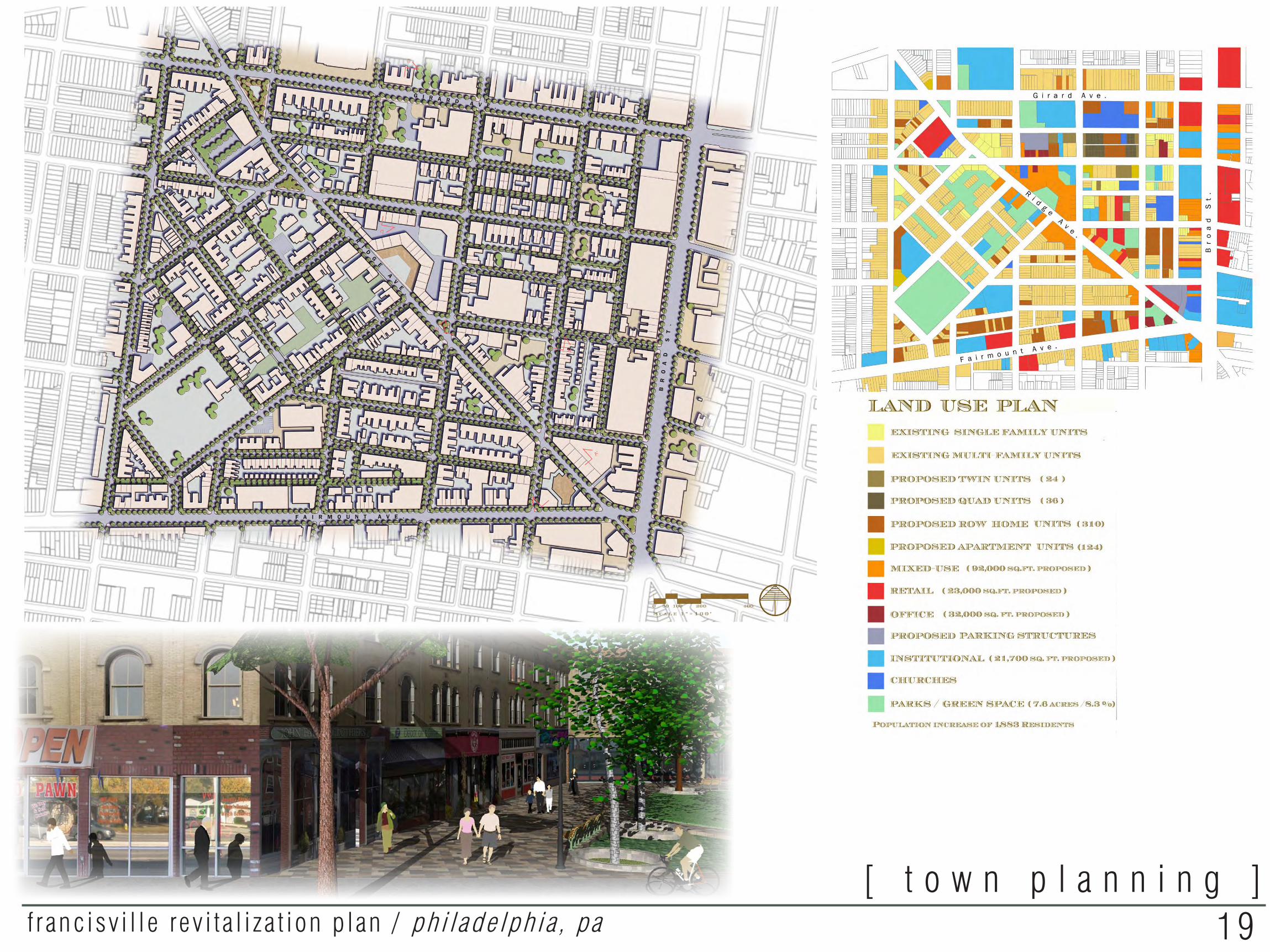
19franc isv i l l e rev i t a l i za t ion p lan / ph i l ade lph ia , pa[ t o w n p l a n n i n g ]
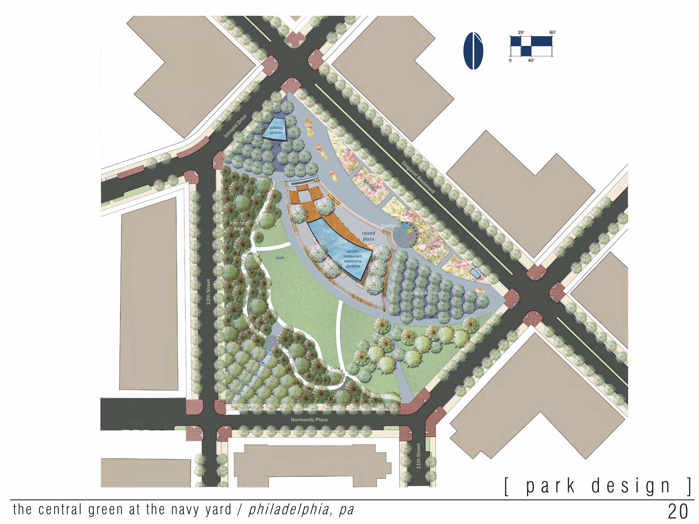
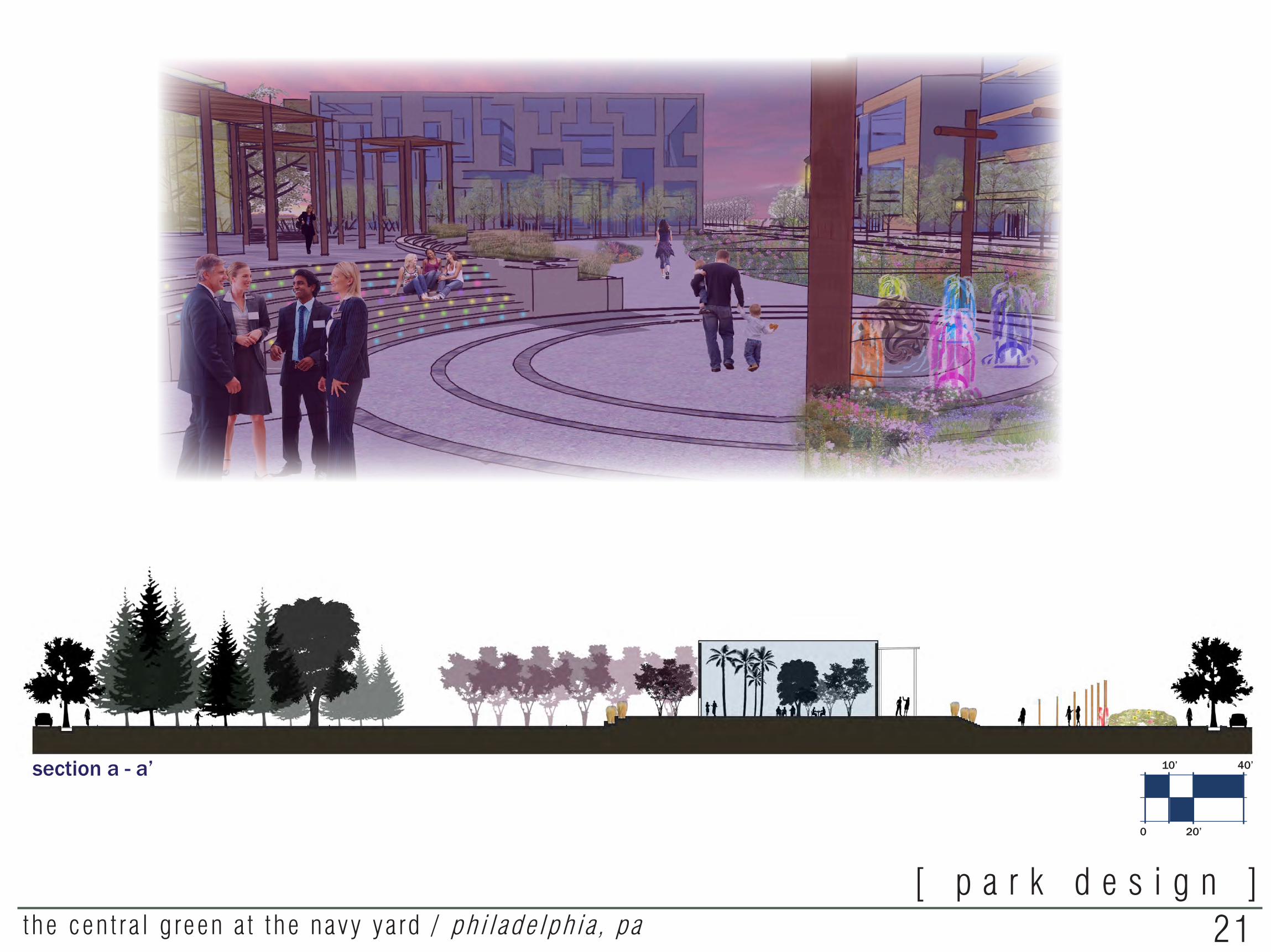
c e n t r a l g r e e n p l a nPhiladelphia Navy Yar d Temple University Department of Landscape Architecture and HorticultureProfessors L. Tai and S. Appel
Rachael Griffith • LA Design Studio VI • Spring 2011
The forms of both structure and void in this park were designed with shipping routes in mind associate the landscape with the seafaring history of the Navy Yard. Swooping paths originate at nodes, usually entrances, and terminate at other path intersections and points of interest within the park. These paths form the structure that divides them, so naturally the structures follow the same curves.
Goalsobjectivesand
Maintain a modern gritty vibe that will appeal to urban pioneers and visionaries.-Use reclaimed timber as sculpture and in the construction of buildings and structures. -Use metal as an edging material in garden beds.-Build structures out of glass, timber, steel, and reclaimed wood planking.
Create an urban-scale park with a feeling of spatial intensity.-Incorporate additional buildings and structure within the park to make it less vast.-Create spaces with varying degrees of enclosure, privacy, and sun exposure using structure, vegetated buffers, and landform.
Include sustainable elements that are both aesthetically pleasing, functional, and educational to the public.-Plant native plants.-Recycle or reuse materials for site furnishings.-Use renewable energy sources such as wind and solar energy for anything requiring power.-Locate architectural forms with passive solar heating and cooling in mind.-Incorporate stormwater BMPs wherever possible.-Include educational signage to explain the importance of these investments.
Incorporate a unique structure to serve as an entrance to a proposed stop on the Broad Street subway line.- Centrally locate the structure and have it serve as a focal point.-Combine the subway stop with an indoor public space building to reduce the scale of the park, provide a respite in bad weather, and provide an interesting transition into the Navy Yard from Center City.
Form spaces suited to a variety of different activities, both active and passive, and include ample open space for corporate functions and special events.-Design with the corporate office employee in mind.-Include functions not found in other nearby parks such as a walking path, moveable Chaise lounges for sunbathing, benches positioned to watch planes take off, a medium sized green for impromptu sports or corporate events, and a restaurant with outdoor seating.
Provide opportunities to display land art and other outdoor exhibitions.-Locate exhibits along major paths parallel to Diagonal Boulevard, on the raised plaza, or interspersed in the forest.-Display the work of local artists.
Diagonal Boulevard
Normandy Place
Intrep
id Driv
e
12th
Str
eet
11th
Str
eet
atrium-restaurant, restrooms,
gardens
raised plaza
lawn
forestedarea
shady bosque
subwaystation
gardens
bus shelter
fountains
0
80’20’
40’
20the cen t ra l g reen a t the navy ya rd / ph i l ade lph ia , pa[ p a r k d e s i g n ]
c e n t r a l g r e e n v i e w sPhiladelphia Navy Yard Temple University Department of Landscape Architecture and HorticultureProfessors L. Tai and S. Appel
Rachael Griffith • LA Design Studio VI • Spring 2011
c
a
a’
viewc
section a - a’
The north entrance to Central Green on Diagonal Boulevard can be considered the main access point into the park. The structure that houses the subway entrance is lo-cated on the corer amongst a shady bosque, providing a calming transition between the bustling subway and the park. Linear gardens dot the main path, leading passers-by in. The raised plaza and atrium are clearly visible, and the closest access point for the plaza to this entrance is an ADA accessible ramp. A shade structure made from reclaimed timber continues the curve of the atrium building and provides a shadier place for outdoor seating on the plaza.
viewc
This newly-built atrium office building in Newtown Square, NY resembles the one featured in this design. Timber posts line the curved front facade, which is made of glass so it can most efficiently utilize sunlight exposure.
This cross section shows the transition between the quieter, more natural “residen-tial” side of the park closest to 12th street to the active urban side along Diagonal Boulevard. The atrium, a built structure with greenery within, serves to connect the two sides and provide a smoothe transition.
sectiona-a’
0
40’10’
20’
b
a
Forms found at the South Cove in Battery Park City (above) such as the maritime-reminiscent shade structures and lights informed this design. The Citygarden in St. Louis (below) inspired some programming elements and their size and relation to each other such as the lawn and natural areas and their connection with the plaza.
c e n t r a l g r e e n v i e w sPhiladelphia Navy Yar d Temple University Department of Landscape Architecture and HorticultureProfessors L. Tai and S. Appel
Rachael Griffith • LA Design Studio VI • Spring 2011
The park’s south entrance along Diagonal Boulevard features a bus stop which will entice people to enter. A shady grove of trees and seating provides a quieter alternative to the sunny, active main path that parallels the Boulevard and is flanked by gardens and the central feature of the park, a raised plaza and atrium.
viewa
viewb
A bird’s-eye view of the park in context with the proposed LEED-certified corporate buildings as well as the existing historic receiving building. Central Green’s design must reconcile the contrasting architectural types by using classic elements such as lawn, forested areas, and more formal plaza spaces to create something new and edgy that will become the most memorable public space in the Navy Yard.
viewa
viewb
21the cen t ra l g reen a t the navy ya rd / ph i l ade lph ia , pa[ p a r k d e s i g n ]
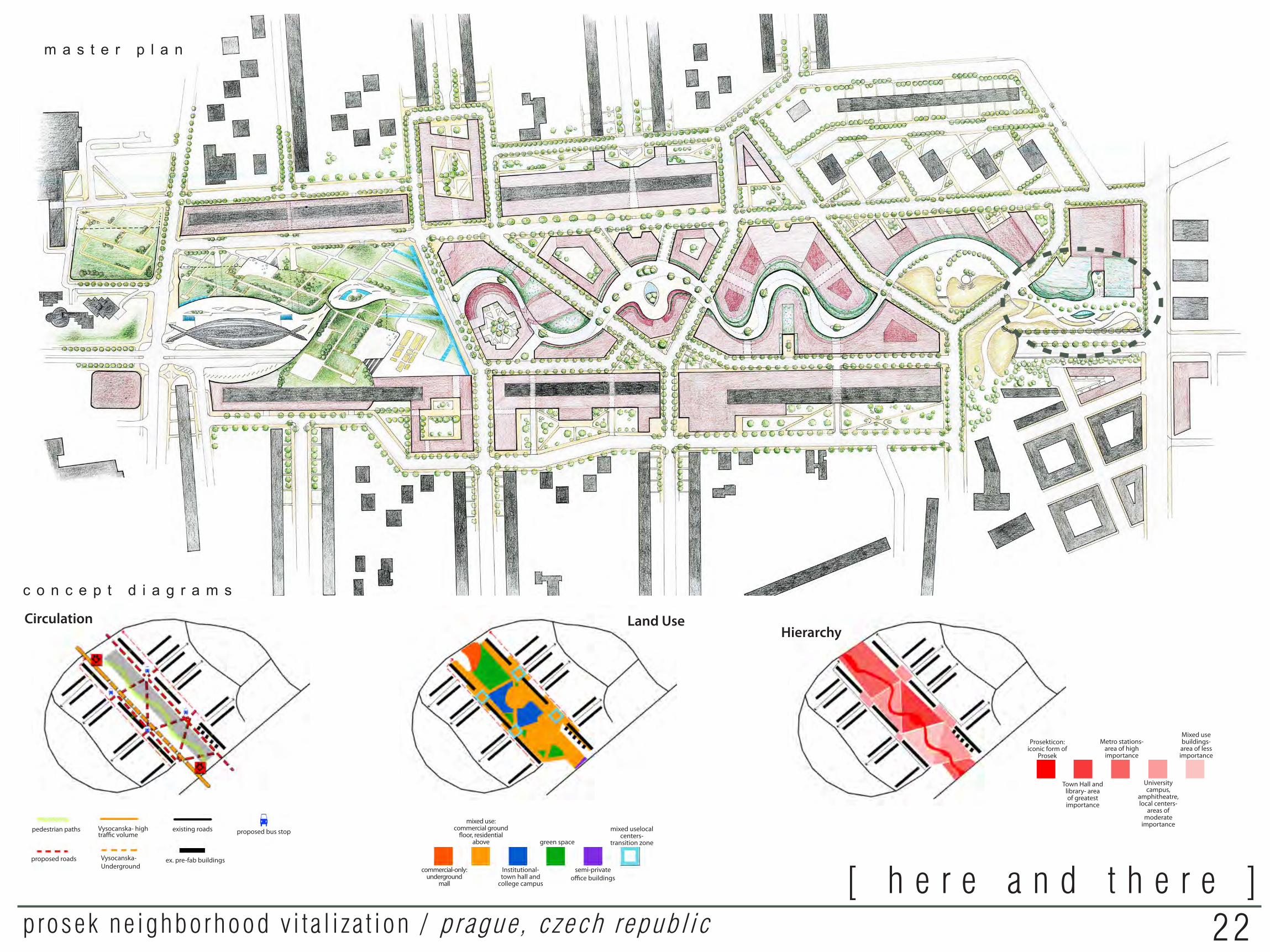
22prosek ne ighborhood v i t a l i za t ion / p rague , czech republ ic[ h e r e a n d t h e r e ]
Land Use
Hierarchy
Mixed use buildings- area of less importance
Prosekticon:iconic form of
Prosek
Town Hall and library- area of greatest importance
Metro stations- area of high importance
University campus,
amphitheatre, local centers-
areas of moderate
importance
Design Intent• Create an iconic form of Prosek with which the town
and word “Prosek” itself will be re-associated• Provide new cultural, recreational and entertainment
functions to bring people into Prosek• Create a memorable, dense, mixed-use development in
the center to unite the now-divided sides• Combine small scattered stores and offices into
complexes to act as transition zones between the existing local and new district zones of Prosek
• Connect these new complexes with streets to further connect the sides of Prosek
• Create calmer, more pedestrian-friendly streets• Provide a large underground parking lot• Strenthen the thresholds to improve the arrival
sequence • Establish a clear hierarchy of built forms, paths, and
spaces• Design a unique development that both stands out
from the rest of Prague yet is more united with it to engender community pride
• All new development will have the intent of environmental sustainability
con c e p tdiagrams
Circulation
pedestrian paths
proposed roads
Vysocanska- high traffic volume
Vysocanska-Underground
existing roads
ex. pre-fab buildings
proposed bus stopmixed uselocal
centers- transition zone
commercial-only:underground
mall
mixed use:commercial ground
floor, residential above
Institutional- town hall and
college campus
green space
semi-private office buildings
m a s t e r p l a n
c o n c e p t d i a g r a m s
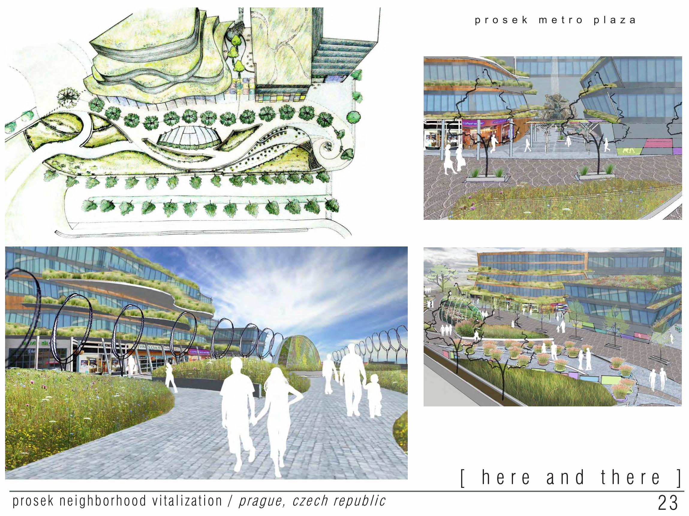
p r o s e k m e t r o p l a z a
23prosek ne ighborhood v i t a l i za t ion / p rague , czech republ ic[ h e r e a n d t h e r e ]

Trotter’s Creek Master Plan
I created this presentation graphic to aid administrators at Kean University in Union, NJ in understanding the spatial, cultural, and environmental importance the creek plays in the campus’ landscape.
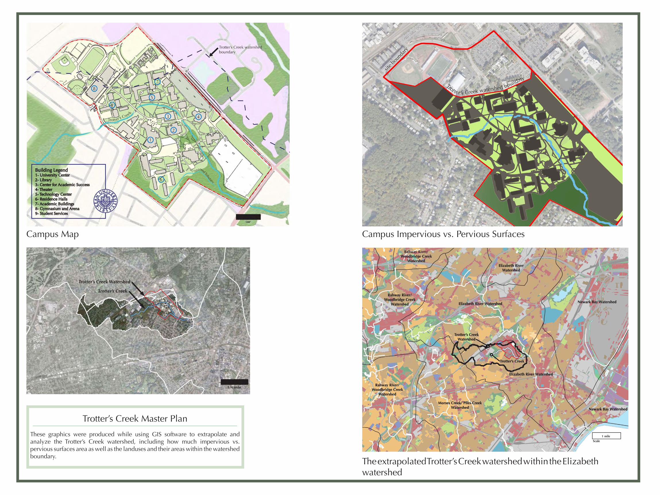
Trotter’s Creek Master Plan
These graphics were produced while using GIS software to extrapolate and analyze the Trotter’s Creek watershed, including how much impervious vs. pervious surfaces area as well as the landuses and their areas within the watershed boundary.
Campus Impervious vs. Pervious Surfaces
The extrapolated Trotter’s Creek watershed within the Elizabeth watershed
Campus Map
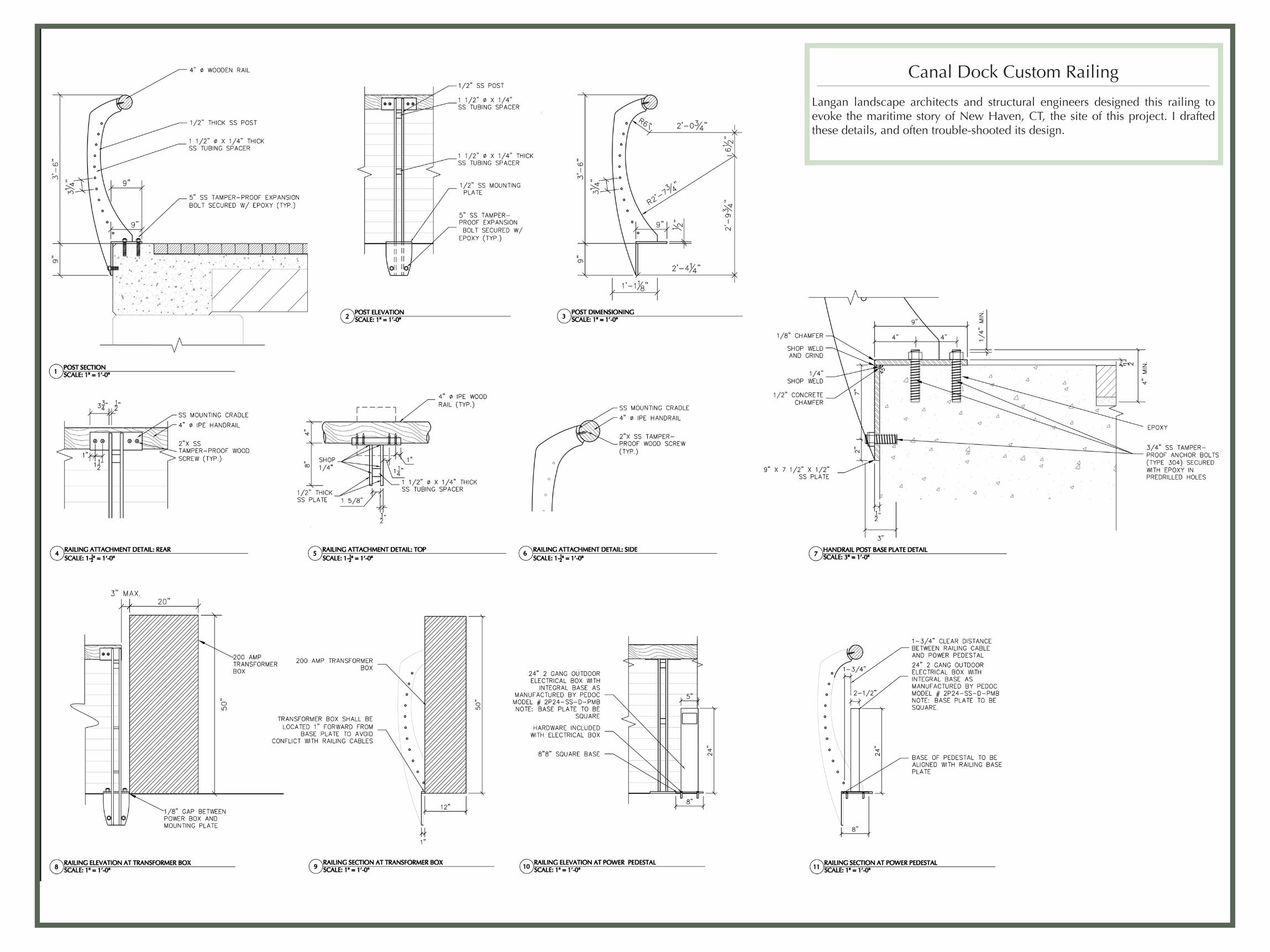
Canal Dock Custom Railing
Langan landscape architects and structural engineers designed this railing to evoke the maritime story of New Haven, CT, the site of this project. I drafted these details, and often trouble-shooted its design.
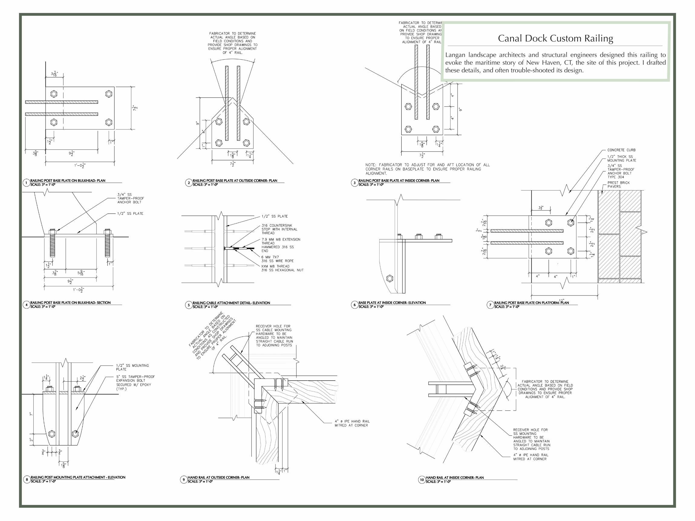
Canal Dock Custom Railing
Langan landscape architects and structural engineers designed this railing to evoke the maritime story of New Haven, CT, the site of this project. I drafted these details, and often trouble-shooted its design.
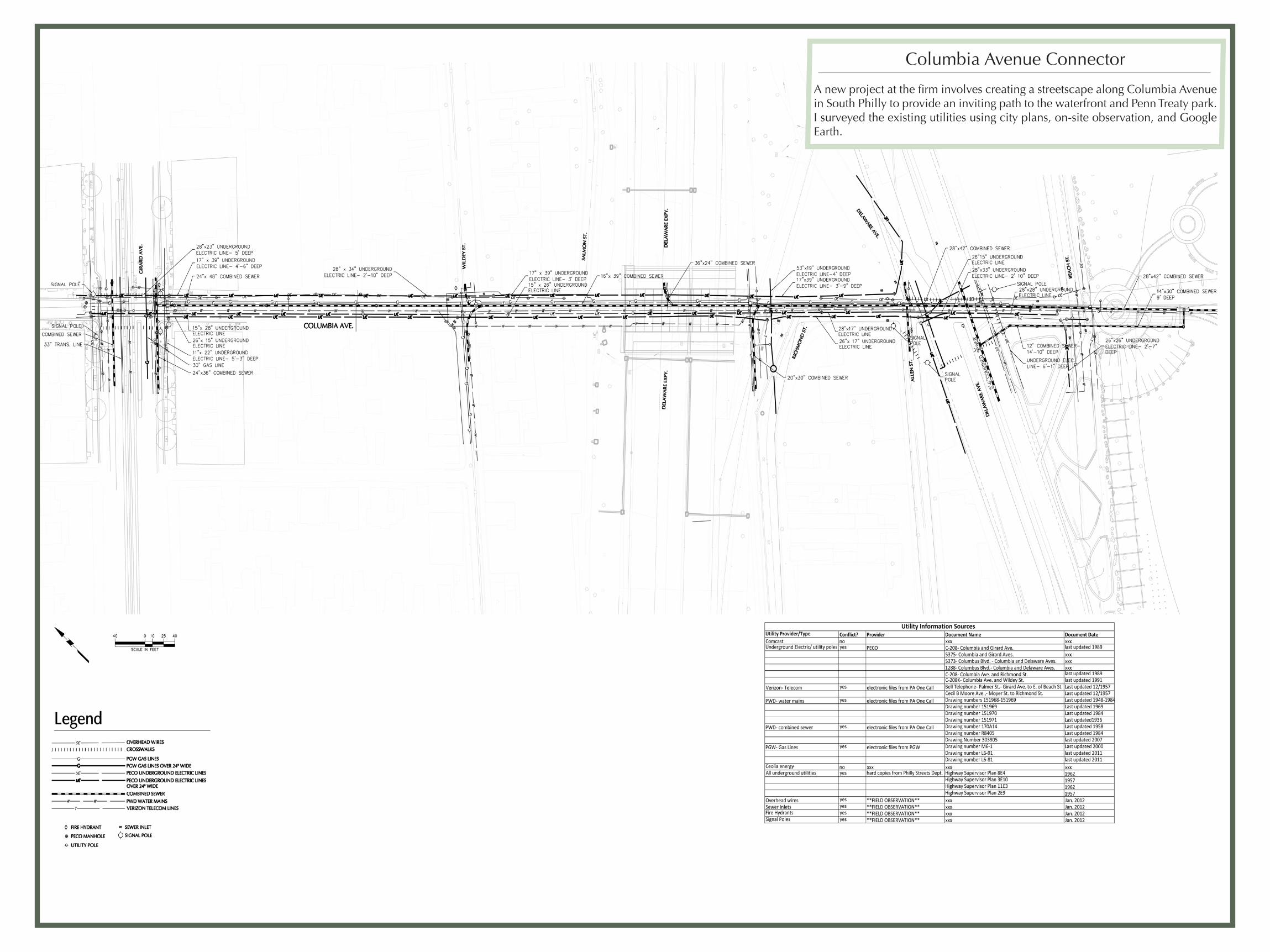
Columbia Avenue Connector
A new project at the firm involves creating a streetscape along Columbia Avenue in South Philly to provide an inviting path to the waterfront and Penn Treaty park. I surveyed the existing utilities using city plans, on-site observation, and Google Earth.