landmark 005 imu (inertial measurement unit) · landmark™ 005 imu (inertial measurement unit)...
TRANSCRIPT

LandMark™ 005 IMU (Inertial Measurement Unit)
Technical User’s Guide
Technical Support
Gladiator Technologies
Attn: Technical Support
8020 Bracken Place SE
Snoqualmie, WA 98065 USA
Tel: 425-396-0829 x241
Fax: 425-396-1129
Email: [email protected]
Web: www.gladiatortechnologies.com

LandMark™ 005 IMU User’s Guide Page i Rev. 01/18/2018
Copyright © 2018 Gladiator Technologies
1 TABLE OF CONTENTS
1 TABLE OF CONTENTS .................................................................................................................. i
2 TABLE OF FIGURES .................................................................................................................... iii
3 SAFETY AND HANDLING INFORMATION ......................................................................................1
4 GETTING STARTED .....................................................................................................................1
4.1 RS-422/485 TO USB POWER SUPPLY & CONVERTER CABLE .................................................................. 3 4.2 LMRK005 IMU MATING CONNECTOR ............................................................................................... 3 4.3 STOP! READ THIS FIRST .................................................................................................................... 3 4.4 INSTALLING THE LINX SDM-USB-QS-S DRIVERS .................................................................................. 4
4.4.1 Introduction................................................................................................................................ 4 4.4.2 Installing the Direct Drivers ........................................................................................................ 5
4.5 GLAMR SOFTWARE INSTALLATION ....................................................................................................... 9 4.6 SELECT APPLICABLE BAUD RATE ....................................................................................................... 12 4.7 SELF-TEST IN GLAMR ...................................................................................................................... 13 4.8 SETTING THE MODE AND DATA RATE ................................................................................................ 15
4.8.1 Set IMU Mode 500 Hz Data Rate .............................................................................................. 16 4.9 UNIT DISPLAY OPTIONS ................................................................................................................... 17 4.10 DATA RECORD FEATURE .................................................................................................................. 20 4.11 BANDWIDTH FILTERING CAPABILITY................................................................................................... 22
5 PATENT AND TRADEMARK INFORMATION ................................................................................ 25
6 APPLICABLE EXPORT CONTROLS ............................................................................................... 25
7 USER LICENSE........................................................................................................................... 25
8 STANDARD LIMITED WARRANTY .............................................................................................. 25
9 QUALITY MANAGEMENT SYSTEM ............................................................................................. 25
10 THEORY OF OPERATION ........................................................................................................... 26
11 LandMark™ 005 IMU PRODUCT DESCRIPTION ........................................................................... 28
11.1 OUTLINE AND 3D SOLID MODELS ..................................................................................................... 29 11.1.1 3D Solid Model ......................................................................................................................... 29 11.1.2 Outline Drawing ....................................................................................................................... 30 11.1.3 Outline Exploded View & Axis Orientation ................................................................................ 31
11.2 CENTER OF GRAVITY ....................................................................................................................... 32 11.3 IMU BLOCK DIAGRAM .................................................................................................................... 33 11.4 LANDMARK™ 005 IMU PART NAMING CONVENTION & PART NUMBERS ............................................... 34 11.5 LANDMARK™ 005 IMU PIN ASSIGNMENTS ....................................................................................... 35 11.6 LANDMARK™ 005 IMU PERFORMANCE SPECIFICATION ....................................................................... 35
12 LandMark™ 005 IMU MESSAGE PROTOCOL .............................................................................. 36

LandMark™ 005 IMU User’s Guide Page ii Rev. 01/18/2018
Copyright © 2018 Gladiator Technologies
12.1 SERIAL COMMUNICATION SETTINGS .................................................................................................. 36 12.2 IMU MESSAGE PACKET FORMAT ...................................................................................................... 36 12.3 SAMPLE DATA FORMAT ................................................................................................................... 37 12.4 SYNC INPUT (2.5 KHZ) .................................................................................................................... 38
12.4.1 Specification ............................................................................................................................. 38 12.4.2 Status Bit .................................................................................................................................. 38 12.4.3 Timing Diagram ........................................................................................................................ 38
12.5 BANDWIDTH VS. NOISE ................................................................................................................... 39
13 SAMPLE TEST DATA & TEST METHODS ...................................................................................... 41
13.1 GLADIATOR ATP EXPLANATION ........................................................................................................ 41 13.1.1 Rate Spin Test ........................................................................................................................... 41 13.1.2 IMU Tumble Test ...................................................................................................................... 42
13.2 ANGLE RANDOM WALK AND ALLAN DEVIATION .................................................................................. 43 13.3 VELOCITY RANDOM WALK AND ALLAN DEVIATION .............................................................................. 45 13.4 BIAS IN-RUN ................................................................................................................................. 47 13.5 BIAS AND SCALE FACTOR OVER TEMPERATURE .................................................................................... 51
13.5.1 Gyro Bias over Temperature ..................................................................................................... 51 13.5.2 Gyro Scale Factor over Temperature......................................................................................... 53 13.5.3 Accelerometer Bias over Temperature ...................................................................................... 55 13.5.4 Accelerometer Scale Factor Bias over Temperature .................................................................. 57
13.6 BIAS TURN-ON (FROM A COLD START) .............................................................................................. 59 13.7 RANDOM AND SINE VIBRATION ........................................................................................................ 65
13.7.1 Random Vibration .................................................................................................................... 65 13.7.2 Sine Vibration Test ................................................................................................................... 66 13.7.3 Gyro Sine Vibration Response ................................................................................................... 66 13.7.4 Accelerometer Sine Vibration Response ................................................................................... 67
14 Mounting................................................................................................................................. 69
15 Operation and Troubleshooting ................................................................................................ 69
15.1 TECHNICAL ASSISTANCE................................................................................................................... 69 15.2 AUTHORIZED DISTRIBUTORS AND TECHNICAL SALES REPRESENTATIVES ................................................... 69 15.3 TECHNICAL SUPPORT WEBSITE ......................................................................................................... 70
16 GLOSSARY OF TERMS ............................................................................................................... 72
16.1 ABBREVIATIONS AND ACRONYMS ...................................................................................................... 72 16.2 DEFINITIONS OF TERMS ................................................................................................................... 72

LandMark™ 005 IMU User’s Guide Page iii Rev. 01/18/2018
Copyright © 2018 Gladiator Technologies
2 TABLE OF FIGURES
Figure 1 SDK Power Supply/Self-Test, SDK to PC Cabling .............................................................................. 2
Figure 2 Unit Connector ................................................................................................................................ 3
Figure 3 Read Me First Installation Guide ..................................................................................................... 3
Figure 4 SDK Installation Disc ........................................................................................................................ 4
Figure 5 Files on Installation Disc .................................................................................................................. 5
Figure 6 Driver Setup Wizard ........................................................................................................................ 5
Figure 7 License Agreement Prompt ............................................................................................................. 6
Figure 8 Installation Folder Prompt .............................................................................................................. 6
Figure 9 Driver Package Information Prompt ............................................................................................... 7
Figure 10 Driver Installation Status ............................................................................................................... 8
Figure 11 Glamr Location on SDK CD-ROM ................................................................................................... 9
Figure 12 Glamr Software Shortcut Icon ....................................................................................................... 9
Figure 13 Glamr Screen before Selecting Correct COM Port Settings ......................................................... 10
Figure 14 Confirmed Correct LINX Port with Message "success" ................................................................ 11
Figure 15 Baud Rate Selection for 1000 Hz Data Rate ................................................................................ 12
Figure 16 IMU Data in Full Mode at 1000 Hz Data Rate ............................................................................. 13
Figure 17 Power and Self-Test Momentary Switch ..................................................................................... 13
Figure 18 Self-Test Display When Activated ON ......................................................................................... 14
Figure 19 Mode Selection / Data Rate ........................................................................................................ 15
Figure 20 IMU Mode at 500 Hz Data Rate .................................................................................................. 17
Figure 21 IMU Units of Measure Selection Options .................................................................................... 18
Figure 22 Accelerometer Units of Measure Selection Options .................................................................... 19
Figure 23 Data Record Capability ............................................................................................................... 20
Figure 24 Saving Data Record File Path ...................................................................................................... 21
Figure 25 Saving Data Record Time ............................................................................................................ 22
Figure 26 Select Desired Bandwidth Filter from Drop Down Menu ............................................................ 23
Figure 27 Message Options for Troubleshooting ........................................................................................ 24
Figure 28 LandMark™ 005 IMU vs. 2 Euro Coin & US Quarter ................................................................... 27

LandMark™ 005 IMU User’s Guide Page iv Rev. 01/18/2018
Copyright © 2018 Gladiator Technologies
Figure 29 LandMark™ 005 IMU 3D Solid Model ......................................................................................... 29
Figure 30 LandMark™ 005 IMU Outline Drawing ....................................................................................... 30
Figure 31 Axis Orientation........................................................................................................................... 31
Figure 32 LandMark™ 005 IMU Exploded Outline Drawing (metric in [mm]) ............................................ 31
Figure 33 LandMark™ 005 IMU Block Diagram .......................................................................................... 33
Figure 34 Gladiator Technologies Part Naming Convention ....................................................................... 34
Figure 35 LandMark 005 IMU Part Number Configurations ....................................................................... 34
Figure 36 LandMark™ 005 IMU Pin Assignments and Outputs .................................................................. 35
Figure 37 Serial Communication Settings ................................................................................................... 36
Figure 38 Screenshot of LMRK005 IMU Sample Data ................................................................................. 37
Figure 39 2.5 kHz Timing Diagram .............................................................................................................. 38
Figure 40 IMU Bandwidth vs. Peak-to-Peak Noise 100 Hz .......................................................................... 40
Figure 41 IMU Bandwidth vs. Peak-to-Peak Noise 1 kHz ............................................................................ 40
Figure 42 Rate Spin Test Data ..................................................................................................................... 41
Figure 43 Accelerometer Tumble Test Data ................................................................................................ 42
Figure 44 Angle Random Walk (ARW) ........................................................................................................ 43
Figure 45 Gyroscope Allan Deviation .......................................................................................................... 44
Figure 46 Velocity Random Walk (VRW) ..................................................................................................... 45
Figure 47 Accelerometer Allan Deviation .................................................................................................... 46
Figure 48 X Gyro Bias In-Run ....................................................................................................................... 47
Figure 49 Y Gyro Bias In-Run ....................................................................................................................... 48
Figure 50 Z Gyro Bias In-Run ....................................................................................................................... 48
Figure 51 X Accelerometer Bias In-Run ....................................................................................................... 49
Figure 52 Y Accelerometer Bias In-Run ....................................................................................................... 50
Figure 53 Z Accelerometer In-Run Bias ....................................................................................................... 50
Figure 54 X Gyro Bias over Temperature .................................................................................................... 51
Figure 55 Y Gyro Bias over Temperature .................................................................................................... 52
Figure 56 Z Gyro Bias over Temperature..................................................................................................... 52
Figure 57 X Gyro Scale Factor over Temperature ....................................................................................... 53
Figure 58 Y Gyro Scale Factor over Temperature ........................................................................................ 54
Figure 59 Z Gyro Scale Factor over Temperature ........................................................................................ 54

LandMark™ 005 IMU User’s Guide Page v Rev. 01/18/2018
Copyright © 2018 Gladiator Technologies
Figure 60 X Accelerometer Bias over Temperature ..................................................................................... 55
Figure 61 Y Accelerometer Bias over Temperature ..................................................................................... 56
Figure 62 Z Accelerometer Bias over Temperature ..................................................................................... 56
Figure 63 X Scale Factor over Temperature ................................................................................................ 57
Figure 64 Y Accelerometer Scale Factor over Temperature ........................................................................ 58
Figure 65 Z Accelerometer Scale Factor over Temperature ........................................................................ 58
Figure 66 X Gyro Bias Turn-On .................................................................................................................... 59
Figure 67 Y Gyro Bias Turn-On .................................................................................................................... 60
Figure 68 Z Gyro Bias Turn-On .................................................................................................................... 61
Figure 69 X Accelerometer Bias Turn-On .................................................................................................... 62
Figure 70 Y Accelerometer Bias Turn-On .................................................................................................... 63
Figure 71 Z Accelerometer Bias Turn-On..................................................................................................... 64
Figure 72 Random Vibration Test Data ....................................................................................................... 65
Figure 73 X IMU Sine Vibration Response ................................................................................................... 66
Figure 74 Y IMU Sine Vibration Response ................................................................................................... 66
Figure 75 Z IMU Sine Vibration Response ................................................................................................... 67
Figure 76 X Accelerometer Sine Vibration Response .................................................................................. 67
Figure 77 Y Accelerometer Sine Vibration Response ................................................................................... 68
Figure 78 Z Accelerometer Sine Vibration Response ................................................................................... 68
Figure 79 Website – Select Product Category ............................................................................................. 70
Figure 80 LMRK005 IMU Product Main Webpage ...................................................................................... 71
Figure 81 LMRK005 IMU Product Documentation & Technical Information .............................................. 71

LandMark™ 005 IMU User’s Guide Page 1 Rev. 01/18/2018
Copyright © 2018 Gladiator Technologies
3 SAFETY AND HANDLING INFORMATION • Always use caution when using the LandMark™ 005 IMU!
• Supplying too high an input voltage could permanently damage the unit. Input Power is specified at +3.8 V to +5.5 V maximum. The unit is calibrated at 5 V ± 0.3 V.
• The LMRK005 IMU is a sensitive scientific instrument containing shock and vibration sensitive inertial and other sensors. Excessive shock and/or vibration can damage these sensors and can adversely affect sensor performance and unit output.
• Avoid exposure to electrostatic discharge (ESD). Observe proper grounding whenever handling the LMRK005 IMU.
• Properly attach connector and ensure that it has been wired correctly before applying power to the LMRK005 IMU.
4 GETTING STARTED This section contains directions and references for a quick start to using the LandMark™ 005. For additional support, please contact the distributor representing your location. If there isn’t a local representative for your location, please contact our Headquarters for assistance and someone from our Sales Team will assist you. The LandMark™ 005 IMU Software Development Kit (SDK) is an optional product to assist first time users of the LandMark™ 005 IMU. This kit provides the user everything they need to facilitate a rapid setup and test of the unit. The SDK (P/N SDK-IMU-6) includes display software with user defined options including the following components and is seen in Figure 1:
• Turn-Key Solution for LandMark™ 005 IMU on User PC
• All Cabling, Interface Connectors and Software Included and Ready for Use
• Easy Integration of Direct IMU RS-422/485 to PC’s USB Port
• Includes PC Display Software for IMU
• Data Record Capability
• Multiple User Selected Field Options for Programming and Initializing the Unit
• User Defined Bandwidth Settings and Data Output Rate on IMU
• Self-Test Switch

LandMark™ 005 IMU User’s Guide Page 2 Rev. 01/18/2018
Copyright © 2018 Gladiator Technologies
Figure 1 SDK Power Supply/Self-Test, SDK to PC Cabling
The following steps will allow the user to quickly set up a LandMark™ 005 IMU and interface it with its SDK.
1. Connect all units together per the User Guide under this section (Getting Started) to the PC. Do
not turn on the power yet. Follow all steps in Section 4 carefully.
2. Follow the instructions from the enclosed disc under Linx SW labeled “STOP! Read This First -
Installation Guide” to load the VCP drivers for the USB interface.
3. Copy the Glamr.msi software and setup.exe applications to the PC hard drive from the header
file on the disc.
4. Run the Glamr.msi to install the Glamr and select the com port to LINX if not selected.
5. Apply power to the unit to see data on the screen. Turn the self-test switch to ON to see a
change in the sensor data that ensures the unit is functioning. Then switch OFF.
6. Follow the instructions in the following sections of the User Guide Glamr Software Installation
(Section 4.5) to change any factory settings for your application.

LandMark™ 005 IMU User’s Guide Page 3 Rev. 01/18/2018
Copyright © 2018 Gladiator Technologies
4.1 RS-422/485 to USB Power Supply & Converter Cable Contained in the Software Development Kit (SDK) is a complete RS-422/485 to USB Converter cable including self-test switch. The power supply uses USB power. An RS-422/485 to USB converter (requires additional drivers that are included in a CD-ROM) is also included. This power supply converter cable and self-test switch enables the user to quickly connect the LMRK005 IMU to their PC to ease integration and testing. Connect the cable to the unit and the converter board to the PC with the USB cable. The user should not need to turn on the power switch yet until the rest of the software is installed.
Figure 2 Unit Connector
4.2 LMRK005 IMU Mating Connector The LandMark™ 005 IMU mating connector and mating pins are contained in a separate package to enable customer-specific wiring options. If the SDK was purchased, then the customer also has an RS-422/485 Converter board, USB connector mate, and mating pins.
4.3 STOP! Read This First
Figure 3 Read Me First Installation Guide
You must first install the USB drivers from the enclosed USB Driver CD-ROM before using Glamr to read the unit. Look on the CD-ROM under Linx SW and perform the instructions in the PDF “Read Me First - Installation Guide” (Figure 5).
Note: This driver is designed for Windows programs only.

LandMark™ 005 IMU User’s Guide Page 4 Rev. 01/18/2018
Copyright © 2018 Gladiator Technologies
4.4 Installing the LINX SDM-USB-QS-S Drivers
4.4.1 Introduction The LINX SDM-USB-QS-S module requires that device drivers be installed on the host PC before they can interact. The drivers tell the PC how to talk to the module. These drivers are for Windows 98, XP, NT, Windows 7, and Windows 8. For Windows 10 installation, please see the note. The set for Windows are the direct drivers, which offer program functions that allow a custom application to directly control the module through the USB port.
NOTE: This is for the installation on machines running the Windows 10 Operating System.
1. Install LINX driver first. This is updated for Windows 10 and is found here:
https://linxtechnologies.com/wp/wp-content/uploads/qs_driver_installer.zip
Do NOT use the FTDI device driver that Windows 10 provides. It does not work with the LINX product even though they are using the FTDI parts. The PID was changed so it is unique.
2. When installing Glamr, there will be an error message saying “Combined.OCX could not be registered.” This is due to missing some DLLs. To get these dependencies, user needs to install a Microsoft Redistribution package. This package (language dependent for our foreign customers) can be found at:
https://www.microsoft.com/en-us/download/details.aspx?id=29
Figure 4 SDK Installation Disc

LandMark™ 005 IMU User’s Guide Page 5 Rev. 01/18/2018
Copyright © 2018 Gladiator Technologies
Figure 5 shows which files will be available to the user via the SDK Installation Disc. Test data and a User Guide for the unit are also included. If multiple units are purchased, the respective User Guides for each different product will be located on the disc. The most recent revision of this guide will be available from the product page on the Gladiator website.
Figure 5 Files on Installation Disc
4.4.2 Installing the Direct Drivers The drivers are included in the Linx SW folder and should be saved onto the hard drive of a PC or onto a flash drive. Click on the QS_Driver_Installer.msi for the Setup Wizard.
Click Next
Figure 6 Driver Setup Wizard

LandMark™ 005 IMU User’s Guide Page 6 Rev. 01/18/2018
Copyright © 2018 Gladiator Technologies
Read License, click I agree, then Next
Figure 7 License Agreement Prompt
Click Next upon arrival at the Installation Folder prompt
Figure 8 Installation Folder Prompt

LandMark™ 005 IMU User’s Guide Page 7 Rev. 01/18/2018
Copyright © 2018 Gladiator Technologies
Click on Next at the Driver Package Information prompt
Figure 9 Driver Package Information Prompt
Note: Plug the connector cable into the USB port before you turn the device power on to avoid Windows loading as a mouse driver.
● Windows 8

LandMark™ 005 IMU User’s Guide Page 8 Rev. 01/18/2018
Copyright © 2018 Gladiator Technologies
Allow driver installation to complete
Figure 10 Driver Installation Status

LandMark™ 005 IMU User’s Guide Page 9 Rev. 01/18/2018
Copyright © 2018 Gladiator Technologies
4.5 Glamr Software Installation Now install the Glamr application off of the CD-ROM. Open the Glamr file (Fig. 11) in the enclosed CD-ROM and install the application to the desired location on the hard drive. Note that Glamr display has common software features for IMUs and IMU Triax units.
Figure 11 Glamr Location on SDK CD-ROM
Once Glamr is installed, create a shortcut on your desktop to the application. Right click on the Glamr Software icon on your hard drive file. Select create shortcut. Drag this shortcut file and drop on your desktop, as seen in Figure 12.
Figure 12 Glamr Software Shortcut Icon

LandMark™ 005 IMU User’s Guide Page 10 Rev. 01/18/2018
Copyright © 2018 Gladiator Technologies
Open the Glamr software and a window will appear as in Figure 13.
Figure 13 Glamr Screen before Selecting Correct LINX Port Settings
The bottom of the Gladiator IMU Display may read “IMU serial port (LINX SDM-USB, 115200, 8E1) Error opening.” “LT=1” may also appear if the interface is not LINX. Only one copy of Glamr can be open at a given time. Always make sure there is not another copy open on the task bar. If there are multiple copies of Glamr open, a message will appear at the bottom of the IMU Display window.

LandMark™ 005 IMU User’s Guide Page 11 Rev. 01/18/2018
Copyright © 2018 Gladiator Technologies
Reconnect the USB plug to the SDK. The “LINX” port should have a checkmark next to it. The bottom of the window should now read “IMU serial port (LINX SDM-USB, 115200, 8E1) success,” as shown in Figure 14.
Figure 14 Confirmed Correct LINX Port with Message "success"
Turn on the power switch located on the SDK and you should see data appear in the window as seen in Figure 15. Movement of the IMU will see changes in rate and acceleration for each axis located within the IMU. To see rapid change, the record function will capture real time data without the filter effect on the screen.

LandMark™ 005 IMU User’s Guide Page 12 Rev. 01/18/2018
Copyright © 2018 Gladiator Technologies
4.6 Select Applicable Baud Rate The baud rate needs to be at least 20% higher than the message rate times number of bits per message so that IMU may receive commands from the host. Here is a guideline of relationship between baud rate and message rate:
Baud Rate →
Data Rate ↓
115200 921600 1.5 M 3.0 M Bits/second
100 Yes Yes Yes Yes 19800
200 Yes Yes Yes Yes 39600
500 * Yes Yes Yes 99000
1000 Yes Yes Yes 198000
2500 Yes Yes Yes 495000
5000 Yes Yes 990000
6000 Yes Yes 1188000
Note that the 500 Hz Data Mode is a special case. Please refer to Section 4.8.1 for more details.
Figure 15 Baud Rate Selection for 1000 Hz Data Rate

LandMark™ 005 IMU User’s Guide Page 13 Rev. 01/18/2018
Copyright © 2018 Gladiator Technologies
Figure 16 IMU Data in Full Mode at 1000 Hz Data Rate
The next message “Msg out-of-sequence: exp 0, act 96” indicates that the program saw a skip in the message count. This case will happen at start-up and can be ignored.
4.7 Self-Test in Glamr Glamr includes a self-test function. The user can initiate the self-test by the momentary switch (Fig. 17), contained within the box that is included in the LMRK005 IMU SDK.
Figure 17 Power and Self-Test Momentary Switch

LandMark™ 005 IMU User’s Guide Page 14 Rev. 01/18/2018
Copyright © 2018 Gladiator Technologies
Press the switch button to activate self-test of the sensors. The Glamr display will now show “SELF-TEST” is activated while also showing the data outputs. This message is located just above the data rate status bar. You should see a delta change in the X, Y, and Z sensor outputs when you initiate self-test per the data sheet (Fig. 18).
Figure 18 Self-Test Display When Activated On

LandMark™ 005 IMU User’s Guide Page 15 Rev. 01/18/2018
Copyright © 2018 Gladiator Technologies
4.8 Setting the Mode and Data Rate The SDK software also has a data rate adjustment and data set selection. This feature is selected under Mode as shown in Figure 19. This allows a reduced data set in Spec mode.
Figure 19 Mode Selection / Data Rate

LandMark™ 005 IMU User’s Guide Page 16 Rev. 01/18/2018
Copyright © 2018 Gladiator Technologies
4.8.1 Set IMU Mode 500 Hz Data Rate All IMUs can be put into a 500 Hz data rate mode. This is shown in Figure 20.
NOTE: To reset to another mode once in 500 Hz data rate mode, the unit requires a special procedure if at 115,200 baud rate. Reverting the unit back to any other mode requires a mode click to the desired rate. This will command the unit to wait for a power recycle as per the screen instructions. To see the unit to the new mode upon powering up, turn on power and the new data rate will be shown under the green bar in the center-left “xxx msgs per sec.”

LandMark™ 005 IMU User’s Guide Page 17 Rev. 01/18/2018
Copyright © 2018 Gladiator Technologies
Figure 20 IMU Mode at 500 Hz Data Rate
4.9 Unit Display Options The SDK software also can set the dimensional units of the display. This is selected under Units. Figure 21 shows the Rate unit selection.

LandMark™ 005 IMU User’s Guide Page 18 Rev. 01/18/2018
Copyright © 2018 Gladiator Technologies
Figure 21 IMU Units of Measure Selection Options
Figure 22 shows the Accel unit selection.

LandMark™ 005 IMU User’s Guide Page 19 Rev. 01/18/2018
Copyright © 2018 Gladiator Technologies
Figure 22 Accelerometer Units of Measure Selection Options

LandMark™ 005 IMU User’s Guide Page 20 Rev. 01/18/2018
Copyright © 2018 Gladiator Technologies
4.10 Data Record Feature The SDK software also has a data record feature that captures data outputting from the IMU and puts it into .csv format. This enables the user to easily convert these data files to Excel or database format. The user should click the Start Recording button (Fig. 23) to initiate data record function. When they wish to stop recording, simply click the Stop Recording button.
Figure 23 Data Record Capability

LandMark™ 005 IMU User’s Guide Page 21 Rev. 01/18/2018
Copyright © 2018 Gladiator Technologies
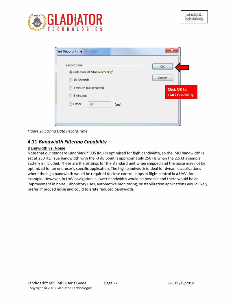
Select “Start Record” and designate the file name and location before the recording begins. To begin Data Record function, click on Open as per Figure 24. After the designated file is established, click the desired length of time to record then click OK (Fig. 25).
Figure 24 Saving Data Record File Path
NOTE: Be sure to look at the Glamr message log to ensure file path is correct and file has successfully been opened for writing.
Once the file has been opened for recording, Glamr will prompt the user to select the recording time. The user has option to specify specific time interval (in seconds), as well as to record until manually stopped. At higher mode rates (100 Hz and 2500 Hz), there is large amount of data being saved, so the file location should be local to the PC or on a file server with high speed access.
Click on Open to start recording.
LandMark™ 005 IMU User’s Guide Page 22 Rev. 01/18/2018
Copyright © 2018 Gladiator Technologies
Figure 25 Saving Data Record Time
4.11 Bandwidth Filtering Capability Bandwidth vs. Noise Note that our standard LandMark™ 005 IMU is optimized for high bandwidth, so the IMU bandwidth is set at 250 Hz. True bandwidth with the -3 dB point is approximately 250 Hz when the 2.5 kHz sample system is included. These are the settings for the standard unit when shipped and the noise may not be optimized for an end-user’s specific application. The high bandwidth is ideal for dynamic applications where the high bandwidth would be required to close control loops in flight control in a UAV, for example. However, in UAV navigation, a lower bandwidth would be possible and there would be an improvement in noise. Laboratory uses, automotive monitoring, or stabilization applications would likely prefer improved noise and could tolerate reduced bandwidth.
Click OK to start recording

LandMark™ 005 IMU User’s Guide Page 23 Rev. 01/18/2018
Copyright © 2018 Gladiator Technologies
Effective with LandMark™ 005 IMU SDK, Gladiator Technologies offers the end-user the capability to set bandwidth filtering in permanent memory that enables the end-user to set lower bandwidth levels than 1 kHz and benefit from the reduced noise of the sensors in the LandMark™ 005 IMU. To utilize this capability, select the Load menu (Fig. 26).
Figure 26 Select Desired Bandwidth Filter from Drop Down Menu
Now select the desired true bandwidth of the IMUs with the software filter. The user can select from Maximum (standard units are shipped with this setting) or from the other bandwidth options all the way down to 1 Hz. Once this is set and the user takes and confirms data with this new setting, the LandMark™ 005 IMU bandwidth filter setting will remain at the setting until the user changes it in the same manner as detailed in this section.
Select desired bandwidth

LandMark™ 005 IMU User’s Guide Page 24 Rev. 01/18/2018
Copyright © 2018 Gladiator Technologies
To help with troubleshooting, users can change what is displayed in the message section of Glamr. This is accessed through the View tab as shown in Figure 27.
Figure 27 Message Options for Troubleshooting
Message section

LandMark™ 005 IMU User’s Guide Page 25 Rev. 01/18/2018
Copyright © 2018 Gladiator Technologies
5 PATENT AND TRADEMARK INFORMATION The LandMark™ 005 IMU is a newly developed unit containing significant intellectual property and it is expected to be protected by United States of America (USA) and other foreign patents pending. LandMark™ is an official and registered Trademark that identifies the Gladiator Technologies brand name for our digital inertial and integrated GPS systems products.
6 APPLICABLE EXPORT CONTROLS The LandMark™ 005 IMU has been self-classified by Gladiator Technologies with pending Commodity Classification by the U.S. Department of Commerce under the Export Administration Regulations (EAR), as ECCN7A994 and as such may be exported without a license using symbol NLR (No License Required) to destinations other than those identified in country group E of supplement 1 to Part 740 (commonly referred to as the T-5 countries) of the Export Administration Regulations. Items otherwise eligible for export under NLR may require a license if the exporter knows or is informed that the items will be used in prohibited chemical, biological, or nuclear weapons or missile activities as defined in Part 774 of the EAR. Copies of official U.S. Department of Commerce Commodity Classifications are available upon request.
7 USER LICENSE Gladiator Technologies grants purchasers and/or consignees of Gladiator’s LandMark™ 005 IMU a no cost, royalty free license for use of the following software code for use with the LandMark™ 005 IMU. Companies or persons not meeting the criteria as a purchaser or consignee are strictly prohibited from use of this code. Users in this category wanting to use the code may contact the factory for other user licensing options.
8 STANDARD LIMITED WARRANTY Gladiator Technologies offers a standard one year limited warranty with the factory’s option to either repair or replace any units found to be defective during the warranty period. Opening the case, mishandling, or damaging the unit will void the warranty. Please see Gladiator Technologies’ Terms & Conditions of sale regarding specific warranty information.
9 QUALITY MANAGEMENT SYSTEM Gladiator Technologies’ Quality Management System (QMS) is certified to AS9100 Rev. C and ISO9001:2008. UL-DQS is the company’s registrar and our certification number is 10012334ASH09. Please visit our website at www.gladiatortechnologies.com to view our current certificates.

LandMark™ 005 IMU User’s Guide Page 26 Rev. 01/18/2018
Copyright © 2018 Gladiator Technologies
10 THEORY OF OPERATION The LandMark™ 005 IMU is a digital 3 Degree of Freedom MEMS (Micro Electro-Mechanical System) IMU that provides delta theta information, as well as temperature. Utilizing Gladiator's proprietary thermal modeling process, this unit is fully temperature compensated, with temperature-corrected bias and scale factor, plus corrected misalignment and g-sensitivity. The unit features:
• The RS-422/485 serial digital interface provides serial data outputs enabling the user to monitor the outputs during use. Internal sampling is done at 8 kHz. The nominal output rate in the LandMark™ 005 IMU is 2.5 kHz ± 5%. An RS-422/485 to USB converter is available in Gladiator's LandMark™ 005 IMU Software Development Kit (SDK) to enable a quick IMU to PC integration and ease of use.
• The MEMS IMU signals with active filtering are sampled when set at 2.5 kHz with a 16-bit A/D converter. The IMUs are available in standard ranges of ± 490°/sec and ± 15g’s.
• The internal temperature sensor outputs are sampled when set at 2.5 kHz with a 16-bit converter. These temperature measurements are co-located with the sensor axes to enable accurate temperature compensation of the IMU outputs.
• The calibration process measures temperature at a minimum of five set points from -40°C to +85°C and a nine-point correction table is generated that identifies temperature based offsets for each of the IMU data sets. Depending upon the variable, up to a 4th order thermal model is used to create a correction model.
• Though a precision mounting block is used in testing the LandMark™ 005 IMU, misalignment error correction is also essential in enabling high performance navigation from a MEMS inertial sensor assembly. The calibration process also corrects and compensates for internal misalignment errors for all sensors in all three axes.
• In addition, "g-sensitivity" errors associated with the IMUs are also modeled and calibrated to correct these performance errors associated with acceleration inputs in all three IMU axes.
• All of the calibration data is then loaded into an internal memory EEPROM enabling a look-up table for thermal modeling correction of the outputs during use.

LandMark™ 005 IMU User’s Guide Page 27 Rev. 01/18/2018
Copyright © 2018 Gladiator Technologies
The LandMark™ 005 IMU data sheet is available to our customers via download on our website. For more information please see Gladiator Technologies’ website at www.gladiatortechnologies.com. Copies of the User’s Guides are available upon request at [email protected]. The LandMark™ 005 IMU SDK software design enables updates to the IMU interface. As these software enhancements and upgrades become approved, Gladiator will make these available to our IMU customers.
Figure 28 LandMark™ 005 IMU vs. 2 Euro Coin & US Quarter
LandMark™ 005 IMU User’s Guide Page 28 Rev. 01/18/2018
Copyright © 2018 Gladiator Technologies
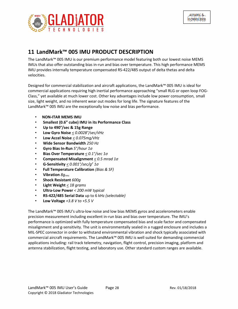
11 LandMark™ 005 IMU PRODUCT DESCRIPTION The LandMark™ 005 IMU is our premium performance model featuring both our lowest noise MEMS IMUs that also offer outstanding bias in-run and bias over temperature. This high performance MEMS IMU provides internally temperature compensated RS-422/485 output of delta thetas and delta velocities. Designed for commercial stabilization and aircraft applications, the LandMark™ 005 IMU is ideal for commercial applications requiring high inertial performance approaching “small RLG or open loop FOG-Class,” yet available at much lower cost. Other key advantages include low power consumption, small size, light weight, and no inherent wear out modes for long life. The signature features of the LandMark™ 005 IMU are the exceptionally low noise and bias performance.
• NON-ITAR MEMS IMU • Smallest (0.6” cube) IMU in its Performance Class • Up to 490°/sec & 15g Range • Low Gyro Noise < 0.0028°/sec/√Hz • Low Accel Noise < 0.075mg/√Hz • Wide Sensor Bandwidth 250 Hz • Gyro Bias In-Run 5°/hour 1σ • Bias Over Temperature < 0.1°/sec 1σ • Compensated Misalignment < 0.5 mrad 1σ • G-Sensitivity < 0.001°/sec/g2 1σ • Full Temperature Calibration (Bias & SF) • Vibration 8grms • Shock Resistant 600g • Light Weight < 18 grams • Ultra-Low Power < 200 mW typical • RS-422/485 Serial Data up to 6 kHz (selectable) • Low Voltage +3.8 V to +5.5 V
The LandMark™ 005 IMU’s ultra-low noise and low bias MEMS gyros and accelerometers enable precision measurement including excellent in-run bias and bias over temperature. The IMU’s performance is optimized with fully temperature compensated bias and scale factor and compensated misalignment and g-sensitivity. The unit is environmentally sealed in a rugged enclosure and includes a MIL-SPEC connector in order to withstand environmental vibration and shock typically associated with commercial aircraft requirements. The LandMark™ 005 IMU is well suited for demanding commercial applications including: rail track telemetry, navigation, flight control, precision imaging, platform and antenna stabilization, flight testing, and laboratory use. Other standard custom ranges are available.

LandMark™ 005 IMU User’s Guide Page 29 Rev. 01/18/2018
Copyright © 2018 Gladiator Technologies
11.1 Outline and 3D Solid Models Please go to the applicable product of interest on our website at www.gladiatortechnologies.com where a user can download the 3D Solid Model, 2D outline drawing, and other product information.
11.1.1 3D Solid Model Figure 29 shows the LandMark™ 005 IMU in a 3D environment.
Figure 29 LandMark™ 005 IMU 3D Solid Model
LandMark™ 005 IMU User’s Guide Page 30 Rev. 01/18/2018
Copyright © 2018 Gladiator Technologies
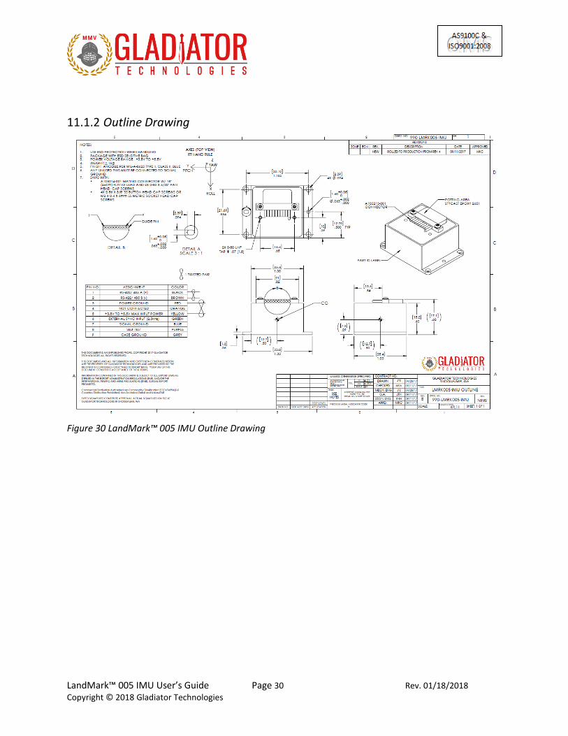
11.1.2 Outline Drawing
Figure 30 LandMark™ 005 IMU Outline Drawing

LandMark™ 005 IMU User’s Guide Page 31 Rev. 01/18/2018
Copyright © 2018 Gladiator Technologies
11.1.3 Outline Exploded View & Axis Orientation
Figure 32 LandMark™ 005 IMU Exploded Outline Drawing (metric in [mm])
Figure 31 Axis Orientation

LandMark™ 005 IMU User’s Guide Page 32 Rev. 01/18/2018
Copyright © 2018 Gladiator Technologies
11.2 Center of Gravity Some applications need to know the CG (center of gravity) of the package, which is simply the mass center. The CG is also near the center line of the package at the midpoint along the z-axis above the base plate with the following offsets:
• X offset = +0.0 inches (0 mm) along the center line
• Y offset = +0.0 inches (0 mm) along the centerline
• Z offset = +0.29 inches (7.4 mm) above the case mounting plane

LandMark™ 005 IMU User’s Guide Page 33 Rev. 01/18/2018
Copyright © 2018 Gladiator Technologies
11.3 IMU Block Diagram
Figure 33 LandMark™ 005 IMU Block Diagram

LandMark™ 005 IMU User’s Guide Page 34 Rev. 01/18/2018
Copyright © 2018 Gladiator Technologies
11.4 LandMark™ 005 IMU Part Naming Convention & Part Numbers
LMRK005 IMU-490-15-100 LMRK 01 IMU 490 15 100 Product Make “LMRK=LandMark™”
Product Model “01”
Product Type “Inertial Measurement Unit”
Gyro Rate Range “490°/sec”
Accelerometer linear range “15g’s”
Specific Unit Configuration “100”
Figure 34 Gladiator Technologies Part Naming Convention
LandMark 005 IMU
LMRK005IMU-490-15-100
Figure 35 LandMark 005 IMU Part Number Configurations

LandMark™ 005 IMU User’s Guide Page 35 Rev. 01/18/2018
Copyright © 2018 Gladiator Technologies
11.5 LandMark™ 005 IMU Pin Assignments The LandMark™ 005 IMU has a nine pin MIL-SPEC connector interface which provides the electrical interface to the host application. The signal pin-out is as follows:
Figure 36 LandMark™ 005 IMU Pin Assignments and Outputs
NOTE: If the input pins have long wires with no termination, they can pick up noise in a high EMI environment and upset the proper operation of the IMU. Pin 6 is particularly vulnerable to noise pickup and can cause data drops.
11.6 LandMark™ 005 IMU Performance Specification See applicable current revision data sheet available on our website at www.gladiatortechnologies.com.

LandMark™ 005 IMU User’s Guide Page 36 Rev. 01/18/2018
Copyright © 2018 Gladiator Technologies
12 LandMark™ 005 IMU MESSAGE PROTOCOL
12.1 Serial Communication Settings
Parameter Value Bits/second: 115200, 921600, 1.5 Mbit, 3.0 Mbit
Data bits: 8
Parity: E
Stop bits: 1
Figure 37 Serial Communication Settings
12.2 IMU Message Packet Format At power-up, the IMU enters operational mode using the last commanded mode setting. Please refer to the Gladiator Technologies Software Reference for additional information.

LandMark™ 005 IMU User’s Guide Page 37 Rev. 01/18/2018
Copyright © 2018 Gladiator Technologies
12.3 Sample Data Format Figure 38 provides a sample IMU data format output in Excel. The real output includes both the header information and data (see rows with MSGCOUNT) that contain actual output data. Also included are the multiplier information, averages, and units of measure for additional clarity. The IMU Software Development Kit also includes the actual Excel file as in Figure 38, so that the user can quickly identify the formulas to use in their system integration directly from the sample data file.
Figure 38 Screenshot of LMRK005 IMU Sample Data
Please note that when the customer uses the Glamr interface it automatically rescales the IMUs. This is displayed in Figure 38, as well as the sample Excel file included in the LMRK005 IMU Software Development Kit (SDK). However, if the user is not using Glamr and inputting directly into their system, then they should use the LSB’s noted above (LSB 0.015 deg/sec for IMUs GYRO, LSB 0.0005g for IMUs ACCELS, and 0.01 degrees for temperature).

LandMark™ 005 IMU User’s Guide Page 38 Rev. 01/18/2018
Copyright © 2018 Gladiator Technologies
12.4 Sync Input (2.5 kHz) The optional input to the IMU is a sync square wave to Pin 6. This allows the data stream to be synchronized to an external clock. For example, if the user wants to supply and sync an external GPS to the IMU the GPS typically generates a 2.5 kHz square ware and this is sent to the IMU when the GPS signal is valid. However, any external 2.5 kHz clock of logic level can be used to synchronize the data.
12.4.1 Specification
• Clock 2.5 kHz ± 5% square wave (40 - 60 duty cycle not critical)
• Data sample starts on the rising edge only
• 3.3 V logic is suggested (-0.3 V < “0” < 0.8 V and 2.0 V < “1” < 5.3 V)
• Input has diode protection for levels below -0.7 V or above 5.5 V to 10.5 V to protect the CPU, but may cause performance problems.
12.4.2 Status Bit The IMU will operate on an internal 5 kHz (which is internally counted down to 2.5 kHz for output) clock until an external clock is detected. Then the IMU will automatically switch over and set Status Bit 1 true. It should be noted that as the internal and external clocks are asynchronous, the transition to Ext Sync will take up to five external clock periods to align. The status bit will be set true during the transition period, as well. When the Message Counter is reset to zero, this will be the first data package with all samples on the external clock. Refer to the timing diagram to see the relationship between the external clock and data transmission (Fig. 39). The IMU will revert to the internal clock if the external clock is not present for 4 mSec. The IMU will revert to the internal clock if the external clock is removed and data will continue to be sent. In most cases the timing of the external sync application is not critical and the data can be used as is.
12.4.3 Timing Diagram
Figure 39 2.5 kHz Timing Diagram

LandMark™ 005 IMU User’s Guide Page 39 Rev. 01/18/2018
Copyright © 2018 Gladiator Technologies
12.5 Bandwidth vs. Noise Note that our standard LandMark™ 005 IMU is optimized for high bandwidth, so the IMUs are set at 250 Hz. True bandwidth which includes the data sampling effects has the -3 dB point is approximately the sample frequency divided by two. These are the settings for the standard unit when shipped and the noise may not be optimized for an end-user’s specific application. The high bandwidth is ideal for dynamic applications where the high bandwidth would be required to close control loops in flight control in a UAV, for example. However, in UAV navigation a lower bandwidth would be possible and the unit would output an improvement in peak-to-peak noise. Laboratory uses, automotive monitoring, or stabilization applications would likely prefer improved (lower) noise and could tolerate reduced bandwidth. The LandMark™ 005 IMU Software Development Kit offers the end-user the capability to set bandwidth filtering in permanent memory. This enables the end-user to set lower bandwidth levels than the sensor bandwidth in order to benefit from the reduced peak-to peak noise of the sensors in the IMU.

LandMark™ 005 IMU User’s Guide Page 40 Rev. 01/18/2018
Copyright © 2018 Gladiator Technologies
Figure 40 IMU Bandwidth vs. Peak-to-Peak Noise 100 Hz
Figure 41 IMU Bandwidth vs. Peak-to-Peak Noise 1 kHz

LandMark™ 005 IMU User’s Guide Page 41 Rev. 01/18/2018
Copyright © 2018 Gladiator Technologies
13 SAMPLE TEST DATA & TEST METHODS
13.1 Gladiator ATP Explanation
13.1.1 Rate Spin Test Data is captured at 100 Hz data rate. The unit is mounted on an orthogonal test fixture and spun at about half of the full scale rate range. Only the rate scale factors and IMU misalignments are measured. The data has been scaled by the test software. The spin rate in the data below was 144°/sec. Each column is the data taken for the axis name at the top of the column during the test at the left. The final values printed in green fall within the “passing” values for the unit (note that all passed).
Figure 42 Rate Spin Test Data
Test gyroX gyroY gyroZ accelX accelY accelZ temp X
PX 143.982 -0.01263 -0.00472 0.014 16.446 -16.935 2749.928
NX -143.977 0.00171 0.0063 -0.024 6.084 -17.644 2749.627
Diff/2 143.9793 -0.00717 -0.00551 0.019 5.181 0.3545 0.1505
Ave 0.00275 -0.00546 0.00079 -0.005 11.265 -17.2895 2749.778
PY -0.0035 143.958 -0.03431 -5.6815 0.201 -16.8595 2752.049
NY 0.00994 -143.976 0.02933 4.69 0.133 -17.69 2751.681
Diff/2 -0.00672 143.9668 -0.03182 -5.18575 0.034 0.41525 0.184
Ave 0.00322 -0.00873 -0.00249 -0.49575 0.167 -17.2748 2751.865
PZ 0.00067 -0.01539 143.9355 5.3535 11.2985 0.532 2753.923
NZ -9E-05 0.00957 -143.945 -5.3435 10.616 0.4945 2753.168
Diff/2 0.00038 -0.01248 143.9405 5.3485 0.34125 0.01875 0.3775
Ave 0.00029 -0.00291 -0.00499 0.005 10.95725 0.51325 2753.546
RSF Norm 0.999856 0.999769 0.999587 Temp ºC
27.52
Gyro
Mis-Align Input Rate
deg/sec
x -0.0067 0.0004 x
y -0.0072 -0.0125 y
z -0.0055 -0.0318 z
Gyro
Mis-align Input Rate
mrad
x -0.047 0.003 x
y -0.050 -0.087 y
z -0.038 -0.221 z

LandMark™ 005 IMU User’s Guide Page 42 Rev. 01/18/2018
Copyright © 2018 Gladiator Technologies
13.1.2 IMU Tumble Test Data is captured at 100 Hz data rate. The unit is mounted on an orthogonal test fixture and placed in ± 1g and ± 0g’s in this test. During this test the IMU biases are measured, as well as the IMU g-sensitivity.
Figure 43 Accelerometer Tumble Test Data
Test gyroX gyroY gyroZ accelX accelY accelZ temp X
PX 0.0022 -0.00767 -0.00305 999.385 0.1695 -0.1175 2752.118
NX 0.00136 -0.00758 -0.00081 -1000.57 0.105 -0.0375 2751.615
Diff/2 0.00042 -4.5E-05 -0.00112 999.9788 0.03225 -0.04 0.2515
Ave 0.00178 -0.00762 -0.00193 -0.59375 0.13725 -0.0775 2751.867
PY 0.00132 -0.00484 0.00106 0.096 999.6435 -0.287 2750.509
NY 0.00217 -0.00453 -0.00086 -0.068 -1000.31 0.19 2750.289
Diff/2 -0.00042 -0.00016 0.00096 0.082 999.9755 -0.2385 0.11
Ave 0.001745 -0.00468 1E-04 0.014 -0.332 -0.0485 2750.399
PZ 0.00078 -0.00408 -0.00107 0.162 0.4045 1000.234 2750.477
NZ 0.00249 -0.00252 -0.00095 -0.0745 -0.4375 -999.832 2750.496
Diff/2 -0.00085 -0.00078 -6E-05 0.11825 0.421 1000.033 -0.0095
Ave 0.001635 -0.0033 -0.00101 0.04375 -0.0165 0.201 2750.487
Bias º/s,mg 0.0017 -0.0052 -0.0009 0.03 0.06 -0.06 27.51
ASF Norm 1.0000 1.0000 1.0000 Temp ºC
0.0017 0.0052 0.0009 0.0 0.1 0.1
0.0026 Input g = Accel In 0.1
Gyro º/s /g 0.0052 g's 0.1
x 0.0004 -0.0004 -0.0009 x
y 0.0000 -0.0002 -0.0008 y
z -0.0011 0.0010 -0.0001 z
0.0004 0.0004 0.0009 Accel
0.0000 0.0002 0.0008 Mis-Align mrads Accel In
0.0011 0.0010 0.0001 0.08 0.12 x
0.0005 0.03 0.42 y
0.0011 -0.04 -0.24 z

LandMark™ 005 IMU User’s Guide Page 43 Rev. 01/18/2018
Copyright © 2018 Gladiator Technologies
13.2 Angle Random Walk and Allan Deviation The unit is mounted on an orthogonal fixture and is turned on with no input. Data is captured at 200 Hz data rate. The white noise due to angular rate is measured. ARW is typically expressed in our datasheets in degrees per second per square root hertz (°/sec/√Hz), which is standard for most MEMS IMUs. However, our performances are now commensurate with higher performing small open loop FOGs and small RLG’s, so we also denote ARW in degrees per square root hour [°/√h].
Figure 44 Angle Random Walk (ARW)
1
10
100
1000
0.001 0.01 0.1 1 10
AR
W d
eg
/hr
Sample Period Sec
X Rate
Y Rate
Z Rate
ARW Line = 0.12 deg/√hr0.0028 /s / √Hz

LandMark™ 005 IMU User’s Guide Page 44 Rev. 01/18/2018
Copyright © 2018 Gladiator Technologies
Figure 45 Gyroscope Allan Deviation

LandMark™ 005 IMU User’s Guide Page 45 Rev. 01/18/2018
Copyright © 2018 Gladiator Technologies
13.3 Velocity Random Walk and Allan Deviation The unit is mounted on an orthogonal fixture and is turned on with no input. Data is captured at 200 Hz data rate. Gladiator measures the velocity error accumulating with time, due to white noise in acceleration. VRW is typically expressed in our datasheets in milli-g per square root hertz (mg/√Hz), which is standard for most MEMS accelerometers. However, our performances are now approaching higher performing quartz based servo accelerometers, so we also denote VRW in meters per second per square root hour [(m/s)/√h].
Figure 46 Velocity Random Walk (VRW)
0.0001
0.001
0.01
0.001 0.01 0.1 1 10VR
W m
/s2
Sample Period Sec
X Accel
Y Accel
Z Accel
VRW Line = 0.03 m/s/√hr0.07 mg/ √Hz

LandMark™ 005 IMU User’s Guide Page 46 Rev. 01/18/2018
Copyright © 2018 Gladiator Technologies
Figure 47 Accelerometer Allan Deviation

LandMark™ 005 IMU User’s Guide Page 47 Rev. 01/18/2018
Copyright © 2018 Gladiator Technologies
13.4 Bias In-Run The unit is placed on an orthogonal test fixture. Data is captured at 100 Hz data rate. Then the bias of the accelerometers and gyros are measured at 1 Hz average. After a five minute warm-up period, the data is taken for five minutes at ambient temperature. The test conditions should be similar to what a user should likely have during initial setup approximately within five minutes after turn-on.
Figure 48 X Gyro Bias In-Run
-1.0
-0.8
-0.6
-0.4
-0.2
0.0
0.2
0.4
0.6
0.8
1.0
0 5000 10000 15000 20000 25000 30000
De
g/s
ec @
1 H
z A
ve
Samples 1Hz Ave
X Gyro In-Run Bias
Drift = 4 /hr over 5 minutes

LandMark™ 005 IMU User’s Guide Page 48 Rev. 01/18/2018
Copyright © 2018 Gladiator Technologies
Figure 49 Y Gyro Bias In-Run
Figure 50 Z Gyro Bias In-Run
-1.0
-0.8
-0.6
-0.4
-0.2
0.0
0.2
0.4
0.6
0.8
1.0
0 5000 10000 15000 20000 25000 30000
De
g/s
ec @
1 H
z A
ve
Samples @ 1Hz Ave
Y Gyro In-Run Bias
Drift = -4 /hr over 5 minutes
-1.0
-0.8
-0.6
-0.4
-0.2
0.0
0.2
0.4
0.6
0.8
1.0
0 5000 10000 15000 20000 25000 30000
De
g/s
ec @
1 H
z A
ve
Samples @ 1Hz Ave
Z Gyro In-Run Bias
Drift = -4 /hr over 5 minutes

LandMark™ 005 IMU User’s Guide Page 49 Rev. 01/18/2018
Copyright © 2018 Gladiator Technologies
Figure 51 X Accelerometer Bias In-Run
-10.000
-8.000
-6.000
-4.000
-2.000
0.000
2.000
4.000
6.000
8.000
10.000
0 5000 10000 15000 20000 25000 30000
Mil
lig
's
Samples @ 1Hz Ave
X Accel In-Run
Drift = -0.034mg over 5 minutes

LandMark™ 005 IMU User’s Guide Page 50 Rev. 01/18/2018
Copyright © 2018 Gladiator Technologies
Figure 52 Y Accelerometer Bias In-Run
Figure 53 Z Accelerometer In-Run Bias
-10.000
-8.000
-6.000
-4.000
-2.000
0.000
2.000
4.000
6.000
8.000
10.000
0 5000 10000 15000 20000 25000 30000
Millig
's
Samples @ 1Hz Ave
Y Accel In-Run
Drift = -0.036mg over 5 minutes
-1010.0
-1008.0
-1006.0
-1004.0
-1002.0
-1000.0
-998.0
-996.0
-994.0
-992.0
-990.0
0 5000 10000 15000 20000 25000 30000
Mil
lig
's
Samples @ 1Hz Ave
Z Accel In-Run
Drift = 0.040mg over 5 minutes

LandMark™ 005 IMU User’s Guide Page 51 Rev. 01/18/2018
Copyright © 2018 Gladiator Technologies
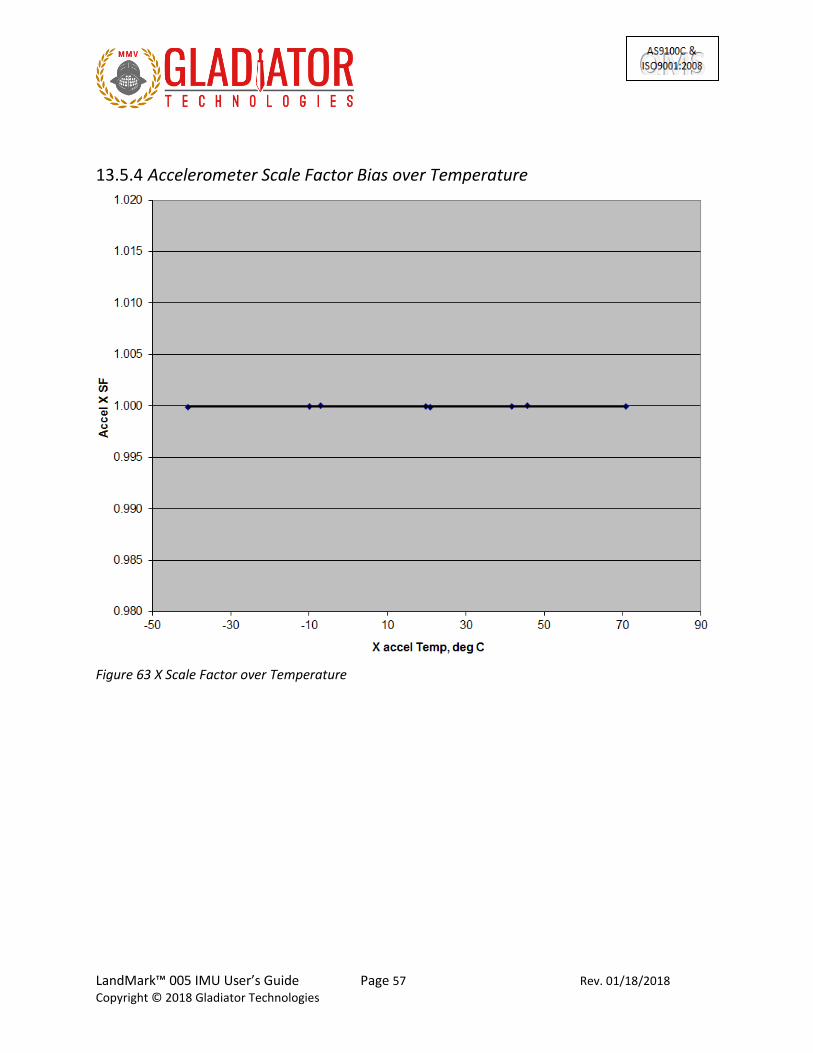
13.5 Bias and Scale Factor over Temperature Data is captured at 100 Hz data rate. The temperature calibration process measures temperature at a minimum of five set points from -40°C to +85°C at a slew rate of approximately 1-2°/minute. A nine point correction table is generated that identifies temperature based offsets for each of the IMU data set. Depending upon the variable, up to a 4th order thermal model is used to create a correction model. The black line is the model fit to the blue diamond data points (Fig. 54).
13.5.1 Gyro Bias over Temperature
Figure 54 X Gyro Bias over Temperature

LandMark™ 005 IMU User’s Guide Page 52 Rev. 01/18/2018
Copyright © 2018 Gladiator Technologies
Figure 55 Y Gyro Bias over Temperature
Figure 56 Z Gyro Bias over Temperature

LandMark™ 005 IMU User’s Guide Page 53 Rev. 01/18/2018
Copyright © 2018 Gladiator Technologies
13.5.2 Gyro Scale Factor over Temperature
Figure 57 X Gyro Scale Factor over Temperature

LandMark™ 005 IMU User’s Guide Page 54 Rev. 01/18/2018
Copyright © 2018 Gladiator Technologies
Figure 58 Y Gyro Scale Factor over Temperature
Figure 59 Z Gyro Scale Factor over Temperature

LandMark™ 005 IMU User’s Guide Page 55 Rev. 01/18/2018
Copyright © 2018 Gladiator Technologies
13.5.3 Accelerometer Bias over Temperature
Figure 60 X Accelerometer Bias over Temperature

LandMark™ 005 IMU User’s Guide Page 56 Rev. 01/18/2018
Copyright © 2018 Gladiator Technologies
Figure 61 Y Accelerometer Bias over Temperature
Figure 62 Z Accelerometer Bias over Temperature
LandMark™ 005 IMU User’s Guide Page 57 Rev. 01/18/2018
Copyright © 2018 Gladiator Technologies
13.5.4 Accelerometer Scale Factor Bias over Temperature
Figure 63 X Scale Factor over Temperature

LandMark™ 005 IMU User’s Guide Page 58 Rev. 01/18/2018
Copyright © 2018 Gladiator Technologies
Figure 64 Y Accelerometer Scale Factor over Temperature
Figure 65 Z Accelerometer Scale Factor over Temperature

LandMark™ 005 IMU User’s Guide Page 59 Rev. 01/18/2018
Copyright © 2018 Gladiator Technologies
13.6 Bias Turn-On (from a Cold Start) The LandMark™ 005 IMU is NOT specified for this condition. This data is supplied for customer reference only. Data is captured at 100 Hz data rate for 25 minutes and we chart 1 Hz average data for the first five minutes. Test conditions assume a unit has been powered off for a minimum of at least five minutes and then data is taken at ambient temperature from initial power-on to determine sample turn-on transient performance. It should be noted that most of the turn-on transient occurs during the initial two minutes after power-on and after that it performs near the specified Bias In-Run performance level.
Figure 66 X Gyro Bias Turn-On

LandMark™ 005 IMU User’s Guide Page 60 Rev. 01/18/2018
Copyright © 2018 Gladiator Technologies
Figure 67 Y Gyro Bias Turn-On

LandMark™ 005 IMU User’s Guide Page 61 Rev. 01/18/2018
Copyright © 2018 Gladiator Technologies
Figure 68 Z Gyro Bias Turn-On

LandMark™ 005 IMU User’s Guide Page 62 Rev. 01/18/2018
Copyright © 2018 Gladiator Technologies
Figure 69 X Accelerometer Bias Turn-On

LandMark™ 005 IMU User’s Guide Page 63 Rev. 01/18/2018
Copyright © 2018 Gladiator Technologies
Figure 70 Y Accelerometer Bias Turn-On

LandMark™ 005 IMU User’s Guide Page 64 Rev. 01/18/2018
Copyright © 2018 Gladiator Technologies
Figure 71 Z Accelerometer Bias Turn-On

LandMark™ 005 IMU User’s Guide Page 65 Rev. 01/18/2018
Copyright © 2018 Gladiator Technologies
13.7 Random and Sine Vibration
13.7.1 Random Vibration Data is captured at 200 Hz data rate on a factory shaker. The unit is subject to random frequencies with total energy contained in the vibration profile of 5.74gRMS. The delta shift for each IMU is measured before and after the run. Also measured during vibe is the Vibration Rectification Coefficients (VRC) of the unit.
Figure 72 Random Vibration Test Data
Axis Sensor Gyro Accel Gyro Accel
Test Units X-G Y-G Z-G X-A Y-A Z-A Abs Ave Input Abs
1 sigma on (deg/sec or mg) 0.0604 992.20
Shift (deg/sec or mg) -0.0014 -0.08 0.0014 0.08
VRE (deg/sec or mg) 0.0034 5.58
VRC (°/hr or µg/grms^2) 0.4 169 0.4 169
1 sigma on (deg/sec or mg) 0.0803 1095.32
Shift (deg/sec or mg) 0.0036 -0.03 0.0036 0.03
VRE (deg/sec or mg) -0.0044 -2.95
VRC (°/hr or µg/grms^2) -0.5 -90 0.5 90
1 sigma on (deg/sec or mg) 0.0604 1091.51
Shift (deg/sec or mg) -0.0022 0.00 0.0022 0.00
VRE (deg/sec or mg) -0.0003 -3.84VRC (°/hr or µg/grms^2) 0.0 -117 0.0 117
°/hr mg
Abs Ave Shift = 8.6 0.04
Stdev Shift = 11.3 0.04
Abs Ave VRC = 0.3 125
grms= 5.74 Stdev VRC = 0.4 158
°/hr/grms2 µg/grms2
X Input
Y Input
Z Input
5.75 grms Random PSD0.02 g2/Hz 50-1000 Hz, -3 dB/octave to 2 kHz

LandMark™ 005 IMU User’s Guide Page 66 Rev. 01/18/2018
Copyright © 2018 Gladiator Technologies
13.7.2 Sine Vibration Test Data is captured at 200 Hz data rate on a factory shaker. The unit is subject to a 5g sine sweep of various frequencies from 30 Hz to 3000 Hz.
13.7.3 Gyro Sine Vibration Response
Figure 73 X IMU Sine Vibration Response
Figure 74 Y IMU Sine Vibration Response
-0.6
-0.4
-0.2
0
0.2
0.4
0.6
0.8
11
63
93
27
74
91
56
55
38
19
19
82
91
14
67
13
10
51
47
43
16
38
11
80
19
19
65
72
12
95
22
93
32
45
71
26
20
92
78
47
29
48
53
11
23
GYRX (°/s)
GYRX (°/s)
-3
-2
-1
0
1
2
3
11
65
43
30
74
96
06
61
38
26
69
91
91
15
72
13
22
51
48
78
16
53
11
81
84
19
83
72
14
90
23
14
32
47
96
26
44
92
81
02
29
75
53
14
08
GYRY (°/s)
GYRY (°/s)
Shaker Resonances
Shaker Turn-Off
Shaker Resonances
Shaker Turn-Off

LandMark™ 005 IMU User’s Guide Page 67 Rev. 01/18/2018
Copyright © 2018 Gladiator Technologies
Figure 75 Z IMU Sine Vibration Response
13.7.4 Accelerometer Sine Vibration Response
Figure 76 X Accelerometer Sine Vibration Response
-0.6
-0.4
-0.2
0
0.2
0.4
0.6
0.81
17
93
35
85
53
77
71
69
89
61
10
75
3
12
54
5
14
33
7
16
12
9
17
92
1
19
71
3
21
50
5
23
29
7
25
08
9
26
88
1
28
67
3
30
46
5
32
25
7
GYRZ (°/s)
GYRZ (°/s)
-10000
-8000
-6000
-4000
-2000
0
2000
4000
6000
8000
10000
12000
1
18
21
36
41
54
61
72
81
91
01
10
92
1
12
74
1
14
56
1
16
38
1
18
20
1
20
02
1
21
84
1
23
66
1
25
48
1
27
30
1
29
12
1
30
94
1
ACCX (mg)
ACCX (mg)
Shaker Turn-Off
Shaker Resonances

LandMark™ 005 IMU User’s Guide Page 68 Rev. 01/18/2018
Copyright © 2018 Gladiator Technologies
Figure 77 Y Accelerometer Sine Vibration Response
Figure 78 Z Accelerometer Sine Vibration Response
-10000
-8000
-6000
-4000
-2000
0
2000
4000
6000
8000
10000
120001
18
38
36
75
55
12
73
49
91
86
11
02
31
28
60
14
69
71
65
34
18
37
1
20
20
8
22
04
5
23
88
2
25
71
9
27
55
6
29
39
3
31
23
0
ACCY (mg)
ACCY (mg)
-12000
-10000
-8000
-6000
-4000
-2000
0
2000
4000
6000
8000
10000
1
18
92
37
83
56
74
75
65
94
56
11
34
7
13
23
8
15
12
9
17
02
0
18
91
1
20
80
2
22
69
3
24
58
4
26
47
52
83
66
30
25
7
32
14
8
ACCZ (mg)
ACCZ (mg)
LandMark™ 005 IMU User’s Guide Page 69 Rev. 01/18/2018
Copyright © 2018 Gladiator Technologies
14 Mounting Mounting for the LandMark™ 005 IMU accommodates both metric and U.S. mounting screws. Mount the unit to a flat surface with 4ea. 2-56 or M2 screws. The minimum torque requirement is 32 in/oz. Be sure that the surface the unit is being mounted to is as clean and as level as possible in order to eliminate potential alignment errors. Adequate mounting to a surface should fall within a flatness of +/- 0.001” or +/- 0.025 mm. Failing to mount the unit in this fashion can result in unaccounted stress in the sensors and therefore may affect data output. Gladiator Technologies strongly encourages the user to mount the unit correctly in the described manner to ensure proper functioning.
15 Operation and Troubleshooting
15.1 Technical Assistance Please contact the factory or your local Gladiator Technologies sales representative's office for technical assistance.
15.2 Authorized Distributors and Technical Sales Representatives If you need additional assistance please contact your local distributor and/or the factor for further technical support: http://www.gladiatortechnologies.com/Intl/Contact.html
Technical Support - USA
Gladiator Technologies
Attn: Technical Support
8020 Bracken Place SE
Snoqualmie, WA 98065 USA
Tel: 425-396-0829 x241
Fax: 425-396-1129
Email: [email protected]
Web: www.gladiatortechnologies.com

LandMark™ 005 IMU User’s Guide Page 70 Rev. 01/18/2018
Copyright © 2018 Gladiator Technologies
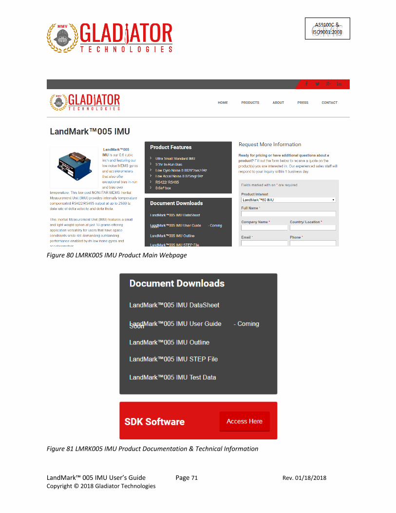
15.3 Technical Support Website Our Technical support webpage has user training videos, the latest software downloads, as well as Remote Desktop Assistance. For direct assistance, Gladiator Technologies offers Remote Assistance and Web Conferencing. For assistance navigating the Gladiator Technologies website, see Figures 79-81.
Figure 79 Website – Select Product Category
LandMark™ 005 IMU User’s Guide Page 71 Rev. 01/18/2018
Copyright © 2018 Gladiator Technologies
Figure 80 LMRK005 IMU Product Main Webpage
Figure 81 LMRK005 IMU Product Documentation & Technical Information

LandMark™ 005 IMU User’s Guide Page 72 Rev. 01/18/2018
Copyright © 2018 Gladiator Technologies
16 GLOSSARY OF TERMS Gladiator Technologies has attempted to define terms as closely as possible to the IEEE IMU and Accelerometer Panel Standards for Inertial Sensor Terminology. Please note that in some instances our definition of a term may vary and in those instances Gladiator Technologies' definition supersedes the IEEE definition. For a complete listing of IEEE's standard for inertial sensor terminology please go to www.ieee.org.
16.1 Abbreviations and Acronyms 6DOF: Six degrees-of-freedom IMU: Inertial Measurement Unit CVG: Coriolis Vibratory IMU ESD: Electro Static Discharge IEEE: The Institute of Electrical and Electronics Engineers MEMS: Micro Electro-Mechanical Systems NLR: No License Required
16.2 Definitions of Terms Acceleration-insensitive drift rate (IMU): The component of environmentally sensitive drift rate not correlated with acceleration. NOTE—Acceleration-insensitive drift rate includes the effects of temperature, magnetic, and other external influences. Acceleration-sensitive drift rate (IMU): The components of systematic drift rate correlated with the first power of a linear acceleration component, typically expressed in (°/h)/g. Accelerometer: An inertial sensor that measures linear or angular acceleration. Except where specifically stated, the term accelerometer refers to linear accelerometer. Allan variance: A characterization of the noise and other processes in a time series of data as a function of averaging time. It is one half the mean value of the square of the difference of adjacent time averages from a time series as a function of averaging time. Angular acceleration sensitivity: (accelerometer): The change of output (divided by the scale factor) of a linear accelerometer that is produced per unit of angular acceleration input about a specified axis, excluding the response that is due to linear acceleration.

LandMark™ 005 IMU User’s Guide Page 73 Rev. 01/18/2018
Copyright © 2018 Gladiator Technologies
(IMU): The ratio of drift rate due to angular acceleration about an IMU axis to the angular acceleration causing it. NOTE—In single-degree-of-freedom IMUs, it is nominally equal to the effective moment of inertia of the gimbal assembly divided by the angular momentum. Bias: (Accelerometer): The average over a specified time of accelerometer output measured at specified operating conditions that have no correlation with input acceleration or rotation. Bias is expressed in [m/s2, g]. (IMU): The average over a specified time of IMU output measured at specified operating conditions that have no correlation with input rotation or acceleration. Bias is typically expressed in degrees per hour (º/h). NOTE—Control of operating conditions may address sensitivities such as temperature, magnetic fields, and mechanical and electrical interfaces, as necessary. Case (IMU, accelerometer): The housing or package that encloses the sensor, provides the mounting surface, and defines the reference axes. Composite error (IMU, accelerometer): The maximum deviation of the output data from a specified output function. Composite error is due to the composite effects of hysteresis, resolution, nonlinearity, non-repeatability, and other uncertainties in the output data. It is generally expressed as a percentage of half the output span. Coriolis acceleration: The acceleration of a particle in a coordinate frame rotating in inertial space, arising from its velocity with respect to that frame. Coriolis vibratory IMU (CVG): A IMU based on the coupling of a structural, driven, vibrating mode into at least one other structural mode (pickoff) via Coriolis acceleration. NOTE—CVGs may be designed to operate in open-loop, force-rebalance (i.e., closed-loop), and/or whole-angle modes. Cross acceleration (accelerometer): The acceleration applied in a plane normal to an accelerometer input reference axis. Cross-axis sensitivity (accelerometer): The proportionality constant that relates a variation of accelerometer output to cross acceleration. This sensitivity varies with the direction of cross acceleration and is primarily due to misalignment. Cross-coupling errors (IMU): The errors in the IMU output resulting from IMU sensitivity to inputs about axes normal to an input reference axis. Degree-of-freedom (DOF) (IMU): An allowable mode of angular motion of the spin axis with respect to the case. The number of degrees-of-freedom is the number of orthogonal axes about which the spin axis is free to rotate.

LandMark™ 005 IMU User’s Guide Page 74 Rev. 01/18/2018
Copyright © 2018 Gladiator Technologies
Drift rate (IMU): The component of IMU output that is functionally independent of input rotation. It is expressed as an angular rate Environmentally sensitive drift rate (IMU): The component of systematic drift rate that includes acceleration-sensitive, acceleration-squared-sensitive, and acceleration-insensitive drift rates. Full-scale input (IMU, accelerometer): The maximum magnitude of the two input limits. G: The magnitude of the local plumb bob gravity that is used as a reference value of acceleration. NOTE 1—g is a convenient reference used in inertial sensor calibration and testing. NOTE 2—In some applications, the standard value of g = 9.806 65 m/s2 may be specified. IMU (IMUscope): An inertial sensor that measures angular rotation with respect to inertial space about its input axis(es). NOTE 1—The sensing of such motion could utilize the angular momentum of a spinning rotor, the Coriolis effect on a vibrating mass, or the Sagnac effect on counter-propagating light beams in a ring laser or an optical fiber coil. G sensitivity (IMU): the change in rate bias due to g input from any direction. Hysteresis error (IMU, accelerometer): The maximum separation due to hysteresis between upscale-going and down-scale-going indications of the measured variable (during a full-range traverse, unless otherwise specified) after transients have decayed. It is generally expressed as an equivalent input. Inertial sensor: A position, attitude, or motion sensor whose references are completely internal, except possibly for initialization. Input angle (IMU): The angular displacement of the case about an input axis. Input axis (IA): (Accelerometer): The axis (es) along or about which a linear or angular acceleration input causes a maximum output. (IMU): The axis (es) about which a rotation of the case causes a maximum output. Input-axis misalignment (IMU, accelerometer): The angle between an input axis and its associated input reference axis when the device is at a null condition. Input limits (IMU, accelerometer): The extreme values of the input, generally plus or minus, within which performance is of the specified accuracy. Input range (IMU, accelerometer): The region between the input limits within which a quantity is measured, expressed by stating the lower- and upper-range value. For example, a linear displacement input range of ±1.7g to ±12g.

LandMark™ 005 IMU User’s Guide Page 75 Rev. 01/18/2018
Copyright © 2018 Gladiator Technologies
Input rate (IMU): The angular displacement per unit time of the case about an input axis. For example, an angular displacement input range of ±150°/sec to ±300°/sec. Input reference axis (IRA) (IMU, accelerometer): The direction of an axis (nominally parallel to an input axis) as defined by the case mounting surfaces, or external case markings, or both. Linear accelerometer: An inertial sensor that measures the component of translational acceleration minus the component of gravitational acceleration along its input axis (es). Linearity error (IMU, accelerometer): The deviation of the output from a least-squares linear fit of the input-output data. It is generally expressed as a percentage of full scale, or percent of output, or both. Mechanical freedom (accelerometer): The maximum linear or angular displacement of the accelerometer’s proof mass, relative to its case. Natural frequency (IMU, accelerometer): The frequency at which the output lags the input by 90°. It generally applies only to inertial sensors with approximate second-order response. Non-gravitational acceleration (accelerometer): The component of the acceleration of a body that is caused by externally applied forces (excluding gravity) divided by the mass. Nonlinearity (IMU, accelerometer): The systematic deviation from the straight line that defines the nominal input-output relationship. Open-loop mode (Coriolis vibratory IMU): A mode in which the vibration amplitude of the pickoff is proportional to the rotation rate about the input axis (es). Operating life (IMU, accelerometer): The accumulated time of operation throughout which an IMU or accelerometer exhibits specified performance when maintained and calibrated in accordance with a specified schedule. Operating temperature (IMU, accelerometer): The temperature at one or more IMU or accelerometer elements when the device is in the specified operating environment. Output range (IMU, accelerometer): The product of input range and scale factor. Output span (IMU, accelerometer): The algebraic difference between the upper and lower values of the output range. Pickoff (mechanical IMU, accelerometer): A device that produces an output signal as a function of the relative linear or angular displacement between two elements.

LandMark™ 005 IMU User’s Guide Page 76 Rev. 01/18/2018
Copyright © 2018 Gladiator Technologies
Plumb bob gravity: The force per unit mass acting on a mass at rest at a point on the earth, not including any reaction force of the suspension. The plumb bob gravity includes the gravitational attraction of the earth, the effect of the centripetal acceleration due to the earth rotation, and tidal effects. The direction of the plumb bob gravity acceleration defines the local vertical down direction, and its magnitude defines a reference value of acceleration (g). Power spectral density (PSD): A characterization of the noise and other processes in a time series of data as a function of frequency. It is the mean squared amplitude per unit frequency of the time series. It is usually expressed in (º/h)2/Hz for IMU scope rate data or in (m/s2)2/Hz or g2/Hz for accelerometer acceleration data. Principal axis of compliance (IMU, accelerometer): An axis along which an applied force results in a displacement along that axis only. Proof mass (accelerometer): The effective mass whose inertia transforms an acceleration along, or about, an input axis into a force or torque. The effective mass takes into consideration rotation and contributing parts of the suspension. Quantization (IMU, accelerometer): The analog-to-digital conversion of a IMU or accelerometer output signal that gives an output that changes in discrete steps, as the input varies continuously. Quantization noise (IMU, accelerometer): The random variation in the digitized output signal due to sampling and quantizing a continuous signal with a finite word length conversion. The resulting incremental error sequence is a uniformly distributed random variable over the interval 1/2 least significant bit (LSB). Random drift rate (IMU): The random time-varying component of drift rate. Random walk: A zero-mean Gaussian stochastic process with stationary independent increments and with standard deviation that grows as the square root of time. Angle random walk (IMU): The angular error buildup with time that is due to white noise in angular rate. This error is typically expressed in degrees per square root of hour [º/√h]. Velocity random walk (accelerometer): The velocity error build-up with time that is due to white noise in acceleration. This error is typically expressed in meters per second per square root of hour [(m/s)/√h]. Rate IMU: An IMU whose output is proportional to its angular velocity with respect to inertial space. Ratio metric output: An output method where the representation of the measured output quantity (e.g., voltage, current, pulse rate, pulse width) varies in proportion to a reference quantity. Rectification error (accelerometer): A steady-state error in the output while vibratory disturbances are acting on an accelerometer.

LandMark™ 005 IMU User’s Guide Page 77 Rev. 01/18/2018
Copyright © 2018 Gladiator Technologies
Repeatability (IMU, accelerometer): The closeness of agreement among repeated measurements of the same variable under the same operating conditions when changes in conditions or non-operating periods occur between measurements. Resolution (IMU, accelerometer): The largest value of the minimum change in input, for inputs greater than the noise level, that produces a change in output equal to some specified percentage (at least 50%) of the change in output expected using the nominal scale factor. Scale factor (IMU, accelerometer): The ratio of a change in output to a change in the input intended to be measured. Scale factor is generally evaluated as the slope of the straight line that can be fitted by the method of least squares to input-output data. Second-order nonlinearity coefficient (accelerometer): The proportionality constant that relates a variation of the output to the square of the input, applied parallel to the input reference axis. Sensitivity (IMU, accelerometer): The ratio of a change in output to a change in an undesirable or secondary input. For example: a scale factor temperature sensitivity of an IMU or accelerometer is the ratio of change in scale factor to a change in temperature. Stability (IMU, accelerometer): A measure of the ability of a specific mechanism or performance coefficient to remain invariant when continuously exposed to a fixed operating condition. Storage life (IMU, accelerometer): The non-operating time interval under specified conditions, after which a device will still exhibit a specified operating life and performance. Strapdown (IMU, accelerometer): Direct-mounting of inertial sensors (without gimbals) to a vehicle to sense the linear and angular motion of the vehicle. Third-order nonlinearity coefficient (accelerometer): The proportionality constant that relates a variation of the output to the cube of the input, applied parallel to the input reference axis. Threshold (IMU, accelerometer): The largest absolute value of the minimum input that produces an output equal to at least 50% of the output expected using the nominal scale factor. Turn-on time (IMU, accelerometer): The time from the initial application of power until a sensor produces a specified useful output, though not necessarily at the accuracy of full specification performance. Warm-up time (IMU, accelerometer): The time from the initial application of power for a sensor to reach specified performance under specified operating conditions. Zero offset (restricted to rate IMUs): The IMU output when the input rate is zero, generally expressed as an equivalent input rate. It excludes outputs due to hysteresis and acceleration.