landfill gas technician basics - smith gardner inc
TRANSCRIPT

Landfill Gas Technician Basics
Presented by Frank Terry
Wellfield Hazards & Safety Practices Landfill Gas Basics Wellfield Monitoring and Tuning Meter Operation and Maintenance Recordkeeping and Reporting GCCS Maintenance Appendix
Program Modules

Wellfield Hazards & Safety Practices
Flammable/Explosive
Suffocation
Hydrogen Sulfide
Personal Gas Monitors
Summary
Wellfield Hazards & Safety Practices Flammable/Explosive
CH4 is flammable from 5% Lower Explosive Level (LEL) to 15% Upper Explosive Level (UEL) of atmospheric concentration
Ignition (spark) in a confined location = EXPLOSION!
Above 15% is not “safe”. LFG dilutes easily and quickly to explosive level
Enclosed or Partially Enclosed Spaces = High Risk Areas (vaults, manholes, buried conduit, buried culverts, etc.)
OSHA defines areas >25% LEL as potentially ignitable which ccannot be entered without proper training, equipment and work practices
CH4 Concentration cannot exceed 10% of LEL when working in a confined space

Humans are extremely sensitive to O2 deficiency
Normal atmosphere is approximately 20.9% O2
Enclosed or partially enclosed spaces = HHigh Risk Areas (trenches, vaults, manholes, buried conduit, buried culverts, etc.)
OSHA defines areas <19.5% O2 as OOxygen Deficient which ccannot be entered without proper training, equipment and work practices
Oxygen deficiency can easily occur in commonly encountered working situations such as bending over or crouching in a trench or leaning inside a manhole or vessel
Wellfield Hazards & Safety Practices Suffocation

Wellfield Hazards & Safety Practices
WWhat could be done to make working around this excavation more safe?

Wellfield Hazards & Safety Practices

Wellfield Hazards & Safety Practices

H2S is produced by microbial decomposition of sulfur compounds. Often associated with drywall buried in the landfill
H2S in LFG is typically in the 25-100ppm range, but can be much higher
NIOSH IDLH (Imminently Dangerous to Life and Health) concentration is 100ppm
OSHA PEL (Personal Exposure Limit) concentration is 10ppm
H2S is very odorous (rotten egg smell) at low concentrations however, exposure levels >50 – 100ppm will cause a very dangerous loss in odor sensitivity
Areas where H2S >10ppm ccannot be entered without proper training, equipment, and work practices
Wellfield Hazards & Safety Practices Hydrogen Sulfide

Usually required by sites when working around LFG
Many different models available to monitor; Methane, Oxygen, H2S, and CO.
Most meters will alarm around generator exhaust, do not turn them off!
Bump test according to your health & safety plan requirements
MMake using it a habit!
Wellfield Hazards & Safety Practices Personal Gas Monitors

Working around Landfill Gas can be DDANGEROUS !
We must not fall into a false sense of safety while working in the wellfield, aanything can happen at any time on a landfill!!
Do not assume you are using safe and approved work practices just because “I’ve always done it this way and nothing ever happened!”
Wellfield Hazards & Safety Practices Summary
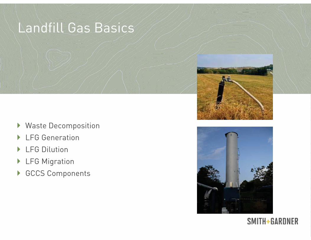
Waste Decomposition
LFG Generation
LFG Dilution
LFG Migration
GCCS Components
Landfill Gas Basics

Landfill Gas Basics: Waste Decomposition

Landfill Gas Basics: Waste Decomposition

Landfill Gas Basics: Waste Decomposition

SStage 4 Anaerobic Decomposition
Methane is produced by anaerobic bacterial decomposition (without air)
As waste is consumed by anaerobic bacteria, the by product is LFG which is primarily CH4+ CO2
O2 kills anaerobic bacteria, it can’t exist in an oxygenated environment
Landfill Gas Basics: Waste Decomposition

SStage 5 Aerobic Decomposition
Aerobic decomposition takes place in the presence of oxygen, resulting in the generation of H2O + CO2 + HEAT
Aerobic decomposition greatly increases the chance of subsurface oxidation or landfill fire
Landfill Gas Basics: Waste Decomposition

The quantity of LFG generated is determined by factors of waste:
Quantity
Waste Type (Characterization)
Age
Moisture content
Temperature of waste
pH (6.7-7.2)
These parameters are not easily altered except for moisture content via leachate reinjection
LFG generation peaks after one year and then decreases at the rate of 2-8% per year
Methane is not produced in Stages 1 through 3
Landfill Gas Basics: LFG Generation

Landfill Gas Basics: LFG Generation

Raw LFG as produced is:
Methane (CH4): 55% - 60%
Carbon Dioxide (CO2): 40% - 45%
Raw LFG is immediately altered by:
Moisture (mainly a function of temperature)
Non-Methane Organic Compounds (NMOC’s)
NMOC’s are stripped from the waste; not generated by decomposition
H2S is produced by bacterial activity on sulfur containing waste material
Landfill Gas Basics: LFG Generation

What alters the “as-produced” methane content of 55% - 60%?
Dilution with air or Oxidation of CH4
Causes lower than normal methane
Loose fittings, cracks in well casing, etc.
Oxidation of waste
Causes lower than normal methane and higher than normal CO2
Introduction of O2 into waste mass
NN2 : O2 ratio normally is 3.8 : 1
Higher ratio is an indication of oxidation or “overpull”
CO2 solubility in water/leachate
Higher than normal CH4 and lower than normal CO2
Analytical error
Some NMOC’s can alter analyzer readings by 10% or more!
Faulty calibration … Metering equipment malfunction
Landfill Gas Basics: LFG Dilution

LFG naturally seeks to move from high to low pressure and concentration
Migration is usually caused by excessive pressure, LFG will follow the path of least resistance, presented by geological conditions such as sand or stone seams or soil fissures
Can easily migrate off the landfill and into adjacent properties at potentially dangerous concentrations
Landfill synthetic or clay base liners block underground LFG migration but penetrations and breeches are common
Migration by concentration (Where LFG will move from high to low zones of concentration) can occur in:
Trenches
Enclosures
Confined Spaces
Landfill Gas Basics: LFG Migration

Landfill Gas Basics: LFG Migration

Landfill Gas Basics: LFG Migration Accident Case Studies
Landfill Gas Explosions
1999 Atlanta
An 8-year-old girl was burned on her arms and legs when playing in an Atlanta playground. The area was reportedly used as an illegal dumping ground many years ago. (Atlanta Journal-Constitution 1999)
1994 Charlotte
While playing soccer in a park built over an old landfill in Charlotte, North Carolina, a woman was seriously burned by a methane explosion. (Charlotte Observer 1994)
1980’s Port Washington
At least 4 homes suffer explosions near the landfill in Port Washington, NY. In 1995, a snack bar at the driving range on the closed landfill also exploded. [EPA Superfund Records]
1975 Sheridan
In Sheridan, Colorado, landfill gas accumulated in a storm drain pipe that ran through a landfill. An explosion occurred when several children playing in the pipe lit a candle, resulting in serious injury to all the children. (USACE 1984)
1969 Winston-Salem
Methane gas migrated from an adjacent landfill into the basement of an armory in Winston-Salem, North Carolina. A lit cigarette caused the gas to explode, killing three men and seriously injuring five others. (USACE 1984)

Landfill Gas Basics: GCCS Components
PPiping Collection Devices Wellheads Condensate Management Gas Handling Equipment Flares

Landfill Gas Basics: GCCS Components Piping
PPiping
Headers & Sub-Headers Generally 6” -18” and larger High Density Polyethylene (HDPE)
Laterals Generally 4” – 8” (HDPE)

Landfill Gas Basics: GCCS Components Piping
HHeader Pipe
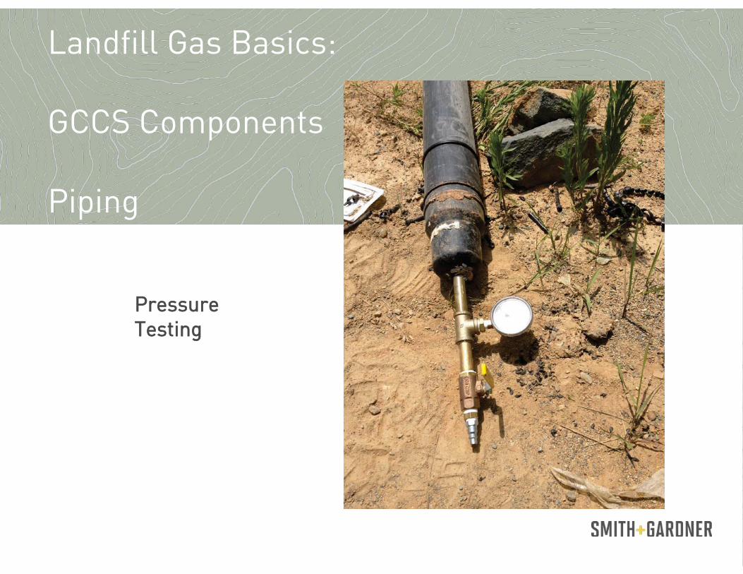
Landfill Gas Basics: GCCS Components Piping
PPressure Testing
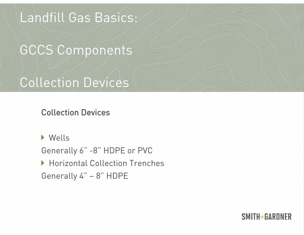
Landfill Gas Basics: GCCS Components Collection Devices
CCollection Devices
Wells Generally 6” -8” HDPE or PVC
Horizontal Collection Trenches Generally 4” – 8” HDPE

Landfill Gas Basics: GCCS Components Collection Devices
DDrill Rig

Landfill Gas Basics: GCCS Components Collection Devices
TTypical Well Construction Details
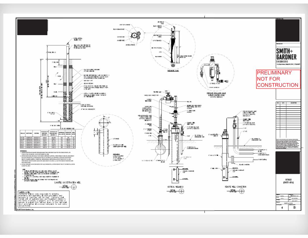
PRELIMINARYNOT FORCONSTRUCTION

Landfill Gas Basics: GCCS Components Collection Devices
PPVC Perforated well casing pipe

Landfill Gas Basics: GCCS Components Collection Devices
BBentonite Hole Plug for well bore hole sealing

Landfill Gas Basics: GCCS Components Collection Devices HHorizontal Collection Trench

Landfill Gas Basics: GCCS Components Wellheads
WWellheads
Pitot Tube - Landtec Orifice Plate - QED Insert - Flo-Wing

Wellheads

Wellheads

Wellheads

Wellheads

Wellheads
Landfill Gas Basics: GCCS Components Condensate Management
CCondensate Management Traps
P-Trap Bucket Trap Sump

Landfill Gas Basics: GCCS Components Condensate Management
PP-Trap

Landfill Gas Basics: GCCS Components: Condensate Management
IIn-line sump

Landfill Gas Basics: GCCS Components Gas Handling
GGas Handling Blowers
Cast Iron Centrifugal (Lamson, Hoffman, HSI, etc.) Fan (New York, etc.)
Compressors Screw (Kobelco, Ingersoll, etc.) Reciprocating (Ariel, etc.)

Landfill Gas Basics: GCCS Components Gas Handling: Blowers CCast Iron
Centrifugal Fan

Landfill Gas Basics: GCCS Components Gas Handling: Compressors
SScrew Reciprocating

Landfill Gas Basics: GCCS Components Flares
FFlares Enclosed Utility Passive
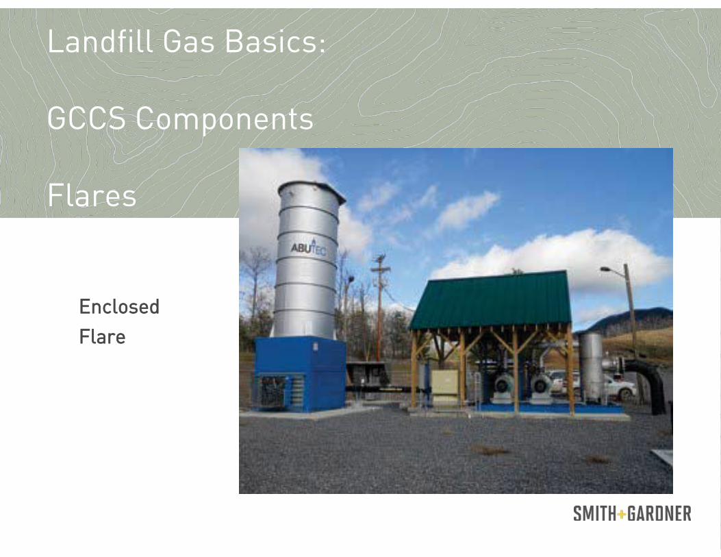
Landfill Gas Basics: GCCS Components Flares
EEnclosed Flare

Landfill Gas Basics: GCCS Components Flares
UUtility Flare

Landfill Gas Basics: GCCS Components Flares
PPassive Flare

Meter Operation and Maintenance
Calibration and Use of the Landtec GEM 5000 Landfill Gas Meter Joe Mauro, Landtec

Wellfield Monitoring and Tuning
Monitoring Frequency
Tuning Parameters
Vacuum and Flow Measurements
Temperature Measurements
Wellhead Adjustments

“CConsistent collection system operation is the key to
optimizing production and maintaining compliance”
Monitor overall system vacuum often and adjust accordingly
Well monitoring intervals are dependent on site specific conditions
Well monitoring frequency ranges from daily to monthly
Problem or inconsistent wells may require more frequent readings
Wellfield Monitoring and Tuning: Monitoring Frequency

System gas quality parameters are usually dictated by site specific processes (flare, engines, turbines, medium or high Btu)
Wellhead tuning thresholds should be consistent with process quality requirements
For trending and troubleshooting purposes, all well data readings and adjustments must be recorded
Wellhead adjustments should not be made during periods of system vacuum or flow instability
Wellfield Monitoring and Tuning: Tuning Parameters

Vacuum is measured in inches of water (or inches of mercury in extremely high vacuum conditions)
Vacuum is applied to the collection system by blowers using dynamic (adjustable by variable frequency drive (VFD)) or manual valves
EEvery effort should be made to maintain a stable system vacuum set point
Flow is generally measured in SCFM (standard cubic feet per minute)
Increasing or decreasing system (header) or applied (well) vacuum does not always result in a linear change in flow and gas quality
Wherever possible, well tuning (based on vacuum and gas quality readings) should be accomplished by incrementally increasing or decreasing flow (scfm), with vacuum being the secondary consideration
Wellfield Monitoring and Tuning: Vacuum and Flow

Pitot Tube
Static Pressure Port
Impact Pressure Port
Temperature Port
System Pressure Port
Landtec Wellheads: Accuflow

Landtec Wellheads: E-Flo
Pitot Tube (internal)
Static Pressure Port
Impact Pressure PortTemperature
Port
System Pressure Port

Static Pressure Port
Impact Pressure Port
Temperature Port
Control Valve
QED Wellheads
Orifice Plate

Wellheads: Flow Wing

LFG flow at the well is usually measured using a pre-fabricated wellhead. Wellhead manufacturers (Landtec, QED, Flo-Wing) utilize differing measurement methods, such as orifice plates, or pitot tubes.
Landtec wellheads calculate flow using a differential pressure measurement in an “impact” (or pitot) tube with a fixed length and diameter, QED wellheads use a differential measurement across a variably sized orifice.
Pipeline flows are usually collected with a stationary measurement and recording device (ex. Orifice, Thermal Mass)
Wellfield Monitoring and Tuning: Flow Measurements

Wellfield Monitoring and Tuning: Flow Measurements
ORIFICE PLATE METER
THERMAL MASS FLOW METER

Wellhead temperature should be recorded using the meter’s integrated temperature probe
Wellhead temperature monitoring point must be installed in a location that reaches directly into the gas flow stream
LFG temperature at the wellhead can vary with changes in flow rate and ambient temperature
All probes and mounted gauges should be periodically checked for accuracy
Wellfield Monitoring and Tuning: Temperature Measurements

Wellhead valve adjustments should be made iincrementally, based on historical data vs. current condition
All parameters must be considered before adjustments are made
Variables such as: barometric pressure, cover integrity, liquid levels, system vacuum changes, wellhead integrity ALL impact gas quality readings in a negative or positive manner
Monitoring frequency must be increased during system vacuum, orifice size, or wellhead changes
Wellfield Monitoring and Tuning: Wellhead Adjustments
Wellfield Monitoring and Tuning:
Well Data Trending
Temperature
Pressure (vacuum)
Gas Content
Flow Rate
Comments

Wellfield Monitoring and Tuning:
Well Data
Recordkeeping and Reporting:
Compliance Reporting
Matt Lamb, S+G

Voluntary Reporting
Carbon Credits - Carbon reductions from landfill methane destruction
- Provides verifiable data trail for verification
Renewable Energy Credits - Offsets fossil fuel emissions
- State-level incentives and programs
- Reporting systems vary by State, e.g. NC-RETS (NC Renewable Energy Tracking System)
National Energy Production Survey Reporting - Dept. of Energy – Energy Information Administration
- Form EIA-923 collects detailed electric power data on electricity generation from fossil and renewable fuels, including LFG
Recordkeeping for Mandatory Systems Addressed in this Presentation Serve as Best Management Practices for Voluntary Systems
Recordkeeping and Reporting:

Mandatory Reporting
40 CFR 258.23 Subtitle D Controlling Explosive Gases - Methane Migration Monitoring
- Reporting subsurface methane at property boundaries and facility structures
- 5% Methane = 100% of Lower Explosive Limit (LEL)
Clean Air Act and Amendments - Subpart Cc—Emission Guidelines and Compliance Times for Municipal Solid Waste Landfills
- Subpart WWW—Standards of Performance for Municipal Solid Waste Landfills
- SSubpart XXX—Standards of Performance for Municipal Solid Waste Landfills that Commenced Construction, Reconstruction, or Modification After July 17, 2014
- SSubpart Cf - Emission Guidelines and Compliance Times for Municipal Solid Waste Landfills
- Subpart AAAA-National Emission Standards for Hazardous Air Pollutants: Municipal Solid Waste Landfills (NESHAP/MACT)
- 40 CFR PART 98— Mandatory Greenhouse Gas Reporting Subpart HH—
Municipal Solid Waste Landfills
Recordkeeping and Reporting:

Reporting Requirements Over Time

Reporting Requirements Over Time

Reporting Requirements Over Time
Reporting Requirements Over Time

Who Needs One?
40 CFR Part 70 – State Operating Permitting under Title V of the CAA
Major Sources of Air Pollutants - 100 tons per year of “criteria” air pollutants, including NOx, CO, VOC
- 10 tons per year of individual Hazardous Air Pollutants (HAPs)
- 25 tons per year of combined HAPs
- Lower thresholds in Non-Attainment Areas
Non-Major Sources subject to NESHAP/NSPS Requirements
MMSW landfills megagrams and 2.5 million m3)
Title V Air Quality Operating Permit

Consolidated Reporting Requirements
Annual Reporting Requirements - Certification of Compliance with All Title V Permit Conditions (State and EPA), including
Reporting of Deviations or Exceedances from Operational or Monitoring Requirements
- Non-Methane Organic Compound (NMOC) Emissions (to determine need for GCCS)
- Air Emission Statements/Inventories
Semiannual Reporting - Summary of Operational and Monitoring Activities, including Deviations from Operational/Monitoring
Conditions (Expanded Reporting if GCCS is Required)
Example Reporting Forms Available from EPA
https://www.epa.gov/title-v-operating-permits/epa-issued-operating-permits
Startup/Shutdown/Malfunction (SSM) Event Reporting (If GCCS is Required) - Verbal reporting within 2 days and written report within 7 days if event is not in SSM Plan
Title V Air Quality Operating Permit
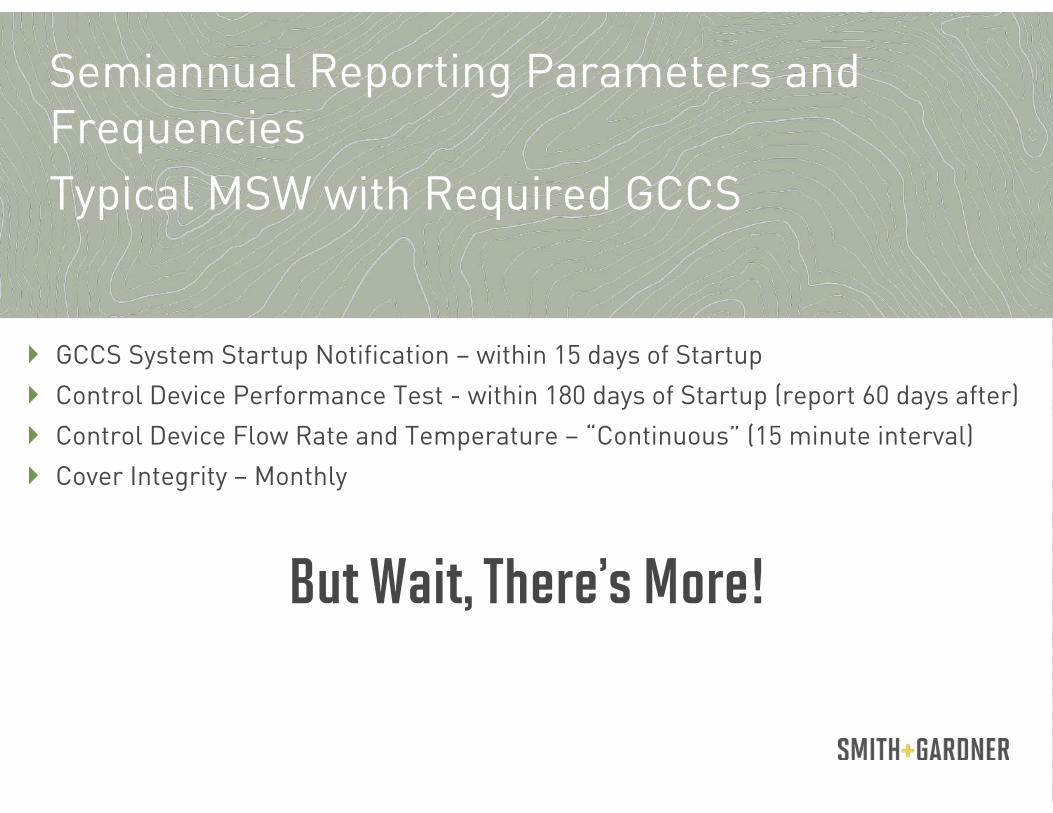
Typical MSW with Required GCCS
GCCS System Startup Notification – within 15 days of Startup
Control Device Performance Test - within 180 days of Startup (report 60 days after)
Control Device Flow Rate and Temperature – “Continuous” (15 minute interval)
Cover Integrity – Monthly
But Wait, There’s More!
Semiannual Reporting Parameters and Frequencies

Typical MSW with Required GCCS
Areas Required to have a GCCS (waste in place >2 year if inactive/>5 years if active)
Methane Surface Emissions Monitoring, Quarterly, UNLESS
Exceedances of 500 PPM or more above background - Re-monitor within 10 days (allowable time for cover maintenance and vacuum increase)
- If re-monitoring still shows an exceedance, repeat above steps and re-monitor within 10 days
- If third monitoring continues to show an exceedance, GCCS expansion is required
- If area of exceedance shows no exceedance during re-monitoring, conduct final monitoring within 1-month of initial exceedance date.
If 1-month monitoring shows an exceedance, GCCS expansion within 120 Days is required
Now it Gets Complicated
Semiannual Reporting Parameters and Frequencies
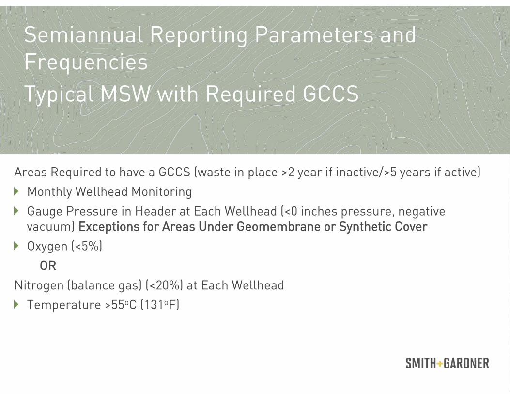
Typical MSW with Required GCCS
Areas Required to have a GCCS (waste in place >2 year if inactive/>5 years if active)
Monthly Wellhead Monitoring
Gauge Pressure in Header at Each Wellhead (<0 inches pressure, negative vacuum) EExceptions for Areas Under Geomembrane or Synthetic Cover
Oxygen (<5%)
OR
Nitrogen (balance gas) (<20%) at Each Wellhead
Temperature >55oC (131oF)
Semiannual Reporting Parameters and Frequencies

Typical MSW with Required GCCS
If Above Parameters Exceed Threshold:
Begin Corrective Action within 55 Days
TIMING IS CRITICAL – ADJUST/RE-MONITOR /RECORD IMMEDIATELY
Re-monitor to Demonstrate Compliance within 115 Days
If re-monitoring continues to show an exceedance, – Decommission Well
– Expand GCCS within 120 Days UNLESS
A Higher Operating Value (HOV, variance), Alternative Compliance Timeline (ACT), or Alternative Operating Parameter (AOP) can be established
Semiannual Reporting Parameters and Frequencies

HOV/ACT/AOP Request Process
Verbal/Email/Written Notification before 15 days elapse
Follow up with written request within 15 days
Confirm if Approval is Required Prior to Certifying Compliance
Communicate With your Regulator
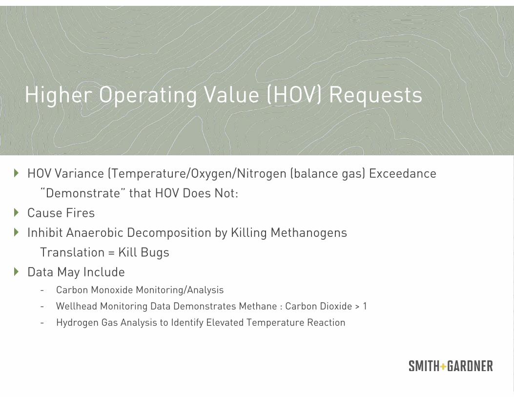
Higher Operating Value (HOV) Requests
HOV Variance (Temperature/Oxygen/Nitrogen (balance gas) Exceedance
“Demonstrate” that HOV Does Not:
Cause Fires
Inhibit Anaerobic Decomposition by Killing Methanogens
Translation = Kill Bugs
Data May Include - Carbon Monoxide Monitoring/Analysis
- Wellhead Monitoring Data Demonstrates Methane : Carbon Dioxide > 1
- Hydrogen Gas Analysis to Identify Elevated Temperature Reaction

Alternative Compliance Timeline (ACT) Requests
Alternative Compliance Timeline to Identify
Federal Guidance Available at https://cfpub.epa.gov/adi/, Control No. 1400019
Steps include – Date and time parameter was exceeded
– Description of corrective actions
– Explanation of why exceedance cannot be corrected within 15 days
– Summary of all relevant/historical data (minimum 6 months)
– Discussion of intended corrective actions and outcomes
– Why GCCS expansion is not warranted, and
– Statement of why compliance timelines are not technically or economically feasible

Alternative Operating Parameter (AOP) Requests
Alternative Operating Parameter to Allow Continued LFG Collection
Federal Guidance Available at https://cfpub.epa.gov/adi/, Control No. 0800040
Something is Better Than Nothing
Commonly Approved for collectors that cannot comply with both pressure AAND O2
– Wells in Older Areas of Declining LFG Generation
– Shallow Wells
– Migration Collectors
– Leachate Collectors
Periodic Monitoring and Operations – Monthly “Burping” to Relieve Accumulated Pressure
– Recording Monthly Monitoring Readings
– Return to Regular Compliance Monitoring if Collector Recovers (Not Likely)

3-Month Stay on Subparts XXX and Cf Expired on August 29, but Legal Action Pending
What Could this Mean to Monitoring and Reporting?
Earlier Installation of GCCS (NMOC 34 Mg/year instead of 50 Mg/year)
Elimination of Oxygen/Nitrogen Exceedance Thresholds (continue to monitor)
“Root Cause Analysis” Requirements and Timelines may Replace ACT and AOP Process
- Complete Root Cause Analysis within 60 Days of Exceedance – Note in Annual/Semiannual Reporting
- Implement Corrective Action and Complete Corrective Action Analysis within 120 Days of Exceedance – Note in Annual/Semiannual
- If exceedance is not corrected within 120 days, submit all information for review and establish alternative implementation timeline
Recent Changes to the New Source Performance Standards and Emissions Guidelines
Recordkeeping and Reporting:
LFG Recordkeeping David Adams, P.E Sanborn-Head

Onsite Recordkeeping
Records of all well monitoring data - Gas Temperature
- Gas Composition
- Flow Rate
- Pressure (vacuum)
Continuous temperature and flow data to all control devices (flares, engines, etc)
Current GCCS drawings (Gas Collection and Control System)
Well Logs
Liquid Level readings
Well Casing Extensions or Reductions
Surface Emissions Monitoring (SEM) data
Start-up, Shut-down, Malfunction (SSM) log
Recordkeeping and Reporting:

GCCS Maintenance & Construction
Nate Timm, ISCO

Glossary
Draeger Tube Sampling
Well Tuning Decision Charts
Appendix

Glossary
Appendix

Appendix
Draeger Tubes
Use
Evaluating Tubes
Tube Selection

Use of a Drager Pump and Drager Colorimetric Gas Detection Tube: • The picture to the right shows the Drager bellows-type gas sampling pump. It accepts a wide range of colorimetric gas detection tubes and includes a counter to count pump strokes. • The picture below shows a Drager colorimetric gas detection tube used to test levels
of a very wide range of specific gases in air.
Appendix: Draeger Tube Sampling

Appendix: Draeger Tube Sampling
Colorimetric Gas Detection Tubes & How They Work: • Colorimetric gas detection tubes all work on a similar principle: aa measured volume
of gas (or air) is drawn through a tube which contains chemicals which change in color in response to the presence of a specific target gas (or range of gases) present in the sample.
• By knowing the volume of gas or air sampled, the amount of color change read on a
linear scale on the colorimetric gas detection tube can be translated into a very accurate measurement of level of gas present, described in percentage of the total air or in parts per million (PPM).
• You may need to make adjustments for temperature and you may need to watch out
for the presence of other gases or chemicals which can interfere with gas detector tube operation.

Appendix:
Draeger Tube Sampling
How a Colorimetric Gas Detector Tube is Used: • Read the gas sampling tube instructions: The gas sampling tube instruction sheet may give various numbers of pump strokes or test air volume to be sampled depending on the level of detection needed. (More pump strokes = more air
= a more sensitive test.) The ends of the glass tube are broken off using a special cutter, usually built into the pump.
• Connect the gas sampling tube to the gas pump: The "outlet" end of the detector tube
is inserted into the gas collecting pump. The "inlet" end of the tube is exposed to the gas to be tested, and the pump is operated for the required number of strokes before looking for a color change on the tube's gas concentration scale. The documentation with each gas detection tube will describe the chemistry of the tube, its accuracy, its calibration, and the color change for which the user is to check.
Appendix:
Draeger Tube Sampling
EEffects of temperature on gas level readings: • The chemistry and thus the sensitivity and ultimate gas concentration reading shown
by a colorimetric gas detection tube may be affected by temperature, it is important to read the temperature data in the gas detection tube specification sheet included with the particular gas detection tube being used.

EEffects of other chemicals and gases on gas level readings: • The gas detection tube instructions may also list other gases which, if present, can
affect the accuracy of the test. The chemistry and thus the sensitivity and ultimate gas concentration reading shown by a colorimetric gas detection tube may therefore be affected by other gases or chemicals present in the location being measured.
• For this reason it is also important to read the characteristics of the gas detector
tube being used, and if there is risk of interference from other gases or chemicals it may be necessary to amend the test procedure, perhaps also including tests for the presence or level of these confounding gases. Sampling of CO in landfill gas requires the use of an additional carbon tube between the CO tube and the sample point.
Appendix: Draeger Tube Sampling

Wellfield Monitoring and Tuning:
Troubleshooting
HHigh Oxygen Monitoring Procedure
:


Wellfield Monitoring and Tuning:
Troubleshooting
HHigh Temperature Monitoring Procedure
130 F (NSPS threshold),
A temperature greater than established variance, and/or a significant (approx. 20%) increase in temperature in a monitoring point that previously had a stable temperature trend


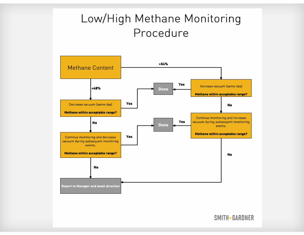
Wellfield Monitoring and Tuning:
Troubleshooting
LLow/High Methane Monitoring Procedure
Less than 48% CH4
Greater than 54% CH4

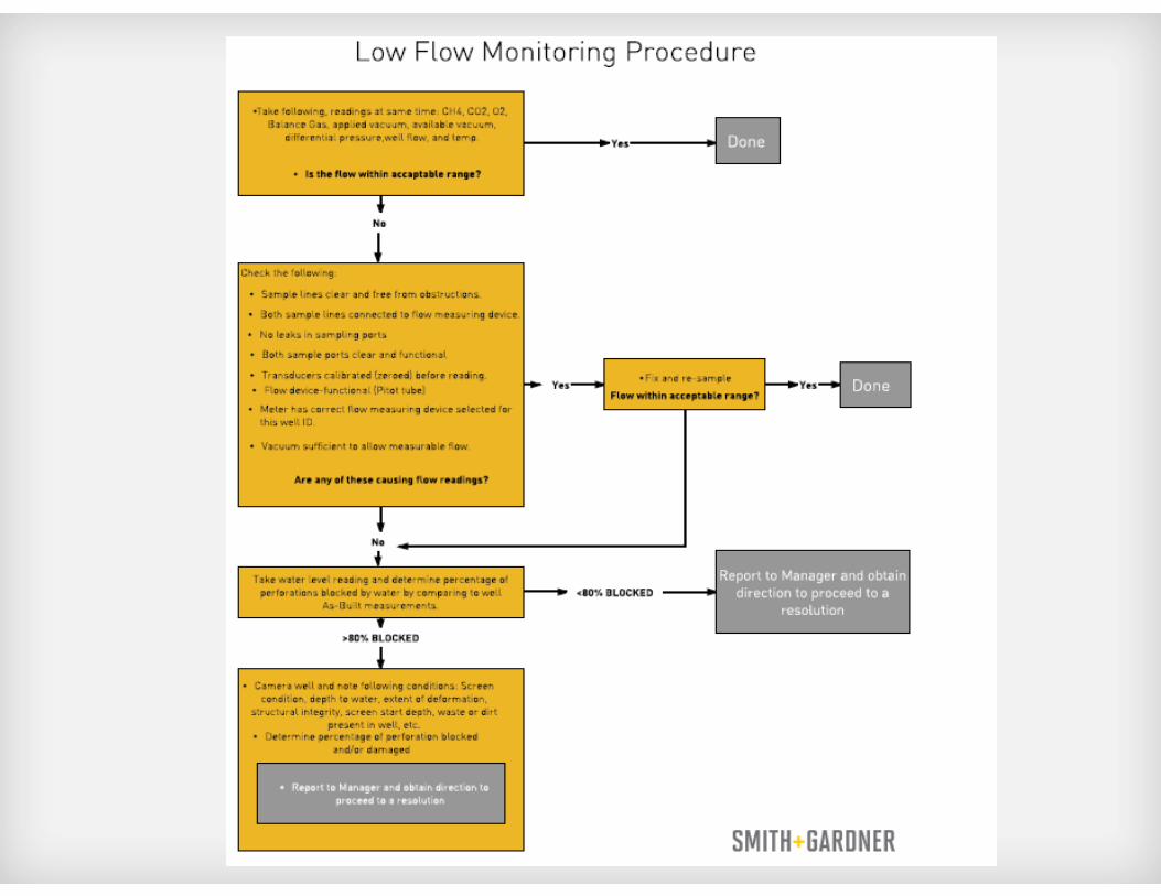
Wellfield Monitoring and Tuning:
Troubleshooting
LLow Flow Monitoring Procedure
Less than 5 SCFM

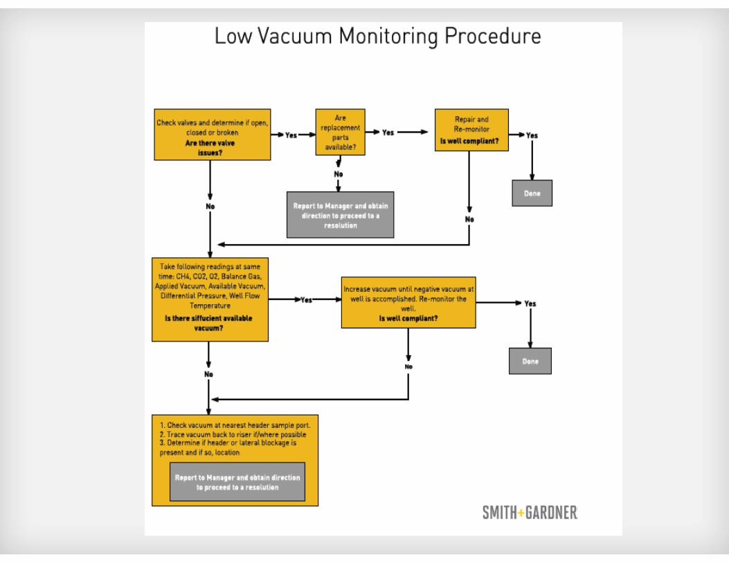
Wellfield Monitoring and Tuning:
Troubleshooting
LLow Vacuum Monitoring Procedure
Less than 0” w.c.
Thanks to our Sponsors

Frank Terry
Project Manager
14 N. Boylan Avenue
Raleigh, NC 27603
TEL 919.828.0577, EXT 142
CELL 919.828.0577
THANK YOU!