laminated object manufacturing
TRANSCRIPT

LAMINAlED OBJECf MANUFACTURING (LOM): A SIMPLER PROCESS
Michael FeyginHelisys, Inc.
Brian HsiehHelisys, Inc.Mechanical, Aerospace, andNuclear Engineering Department,University of California,Los Angeles
IotroductiQn
Basic ConceptWith Laminated Object Manufacturing (LQM) process, three dimensional objects
are manufactured by sequentially laminating and cUtting two-dimensional cross-sections.The.rnediumused.inLOMprocess isaQhesive-coatedsheet•• materials.. As seen in Figure 1,the sheetmateria.l carries the adhesive either on one sideQr both sides, or it cQntains theadhesive ill itself, like woven composite material impregnated with bonding agent. Theadhesive,which can be pre-coatedonto>material or be deposited prior to bonding, enableslayers of sheet material to be attached to each other so as to construct a three-dimensionalobject.
After layer is deposited, peripheries of this layer's cross-section are cut by aQn the information from the CAD model. This bonding-before-cutting
reDea«~ until the full height of the part is reached. (Figure 2)
The process is much faster thancoOlpetitive techniques, sincethe laser does nothave to scan the entire area ofa cross-section. Instead it just has togo around itsperiphery. Layers are glued to the stack virtuaHyinstaIltaneously,substantiaHyreducinglayer .·f0rnlation. time.••Thespeedi<ad~antageofthe .process·grows •with. thesize of the Olanufacturedpan..i.•The.i·ll1()fe··volutne.Qf material.iscontained.withinthepart. thestfQDger is the speed advantage.
The process produces virtually no internal.stfessandassociated with it undesirabledef0rnlation.. Also,becausethe •• in-prQCesspartis •• already .• solid, it. is· convenient tomeas01"ethe actualheightandperfonnreal-titne slicing on the flY. ifighprecision(below .0()5") is achieved due to theabsenceofshrinkageandability.to performrea1-tiJ:ne measurement and slicing.
• <:tll"",,,","<:t. which could

• No support structure is needed Since exterior material remains surrounding the partwhile the LOM process proceeds, it naturally provides a support for overhang andundercut potions of the part. This eliminates extra design time required to createproper supp<>rt structures.
MJcbipe Struetm:e
Figure 3 demonstrates a fundamental structure of a current LOM machine. Themechanical part of the system contains an unwinding and a rewinding roll connected by aribbon of sheet material routed through several idler rollers. These rolls store and supplythe material. The laminated part is grown on a platform capable of a vertical incrementalmovement under the action of a stepper motor. Above the platform is located a heated rollercapable of heating and compressing the ribbon between itself and the stack of laminationson the platform. As a result of a single reciprocal motion of the heated roller the ribbonmaterial is bonded to the top of the stack. An X-Y positioning table carries two mirrorswhich reflect a beam from a C02 laser and a lens which focuses the beam on the uppersurface of the laminated stack so as to cut the very top layer. Scrap pieces remain on theplatform as the part is being built. They are diced by the laser beam into crosshatchedsquares and serve as a support structure for the part. A picture of a LOM machine (model1015) is shown as Figure 4.
The working cycle of an LOM machine is as follows:
• A computer which runs the system is capable of slicing a 3-D solid model into thintwo-dimensional cross-sections. The thickness of each cross-section is equal to thethickness of the material used in the process. At frrst, the geometry of a crosssection is generated by the computer.
• The geometrical information is fed into the LOM system which guides the laserbeam cutting around the periphery of the cross-section. The laser cuts to the depthof one layer of the material. The material which surrounds the cross-section isusually crosshatched by the laser beam into squares to facilitate separation at thecompletion of the process (Figure 5). In the areas where attachment of the materialwhich belongs to the part to the material which surrounds it is undesirable the laserbeam ablates the portions of the bottom layer to prevent bonding. Sometimes finecrosshatch of these portions can achieve virtually the same effect.
Next, the platform moves down. The ribbon moves by an increment exceeding thelength of a cross-section onto the rewinding roll. As the platform moves up, theheated roller moves across the stack while Pressing the ribbon against the stack andbonding it to the upper layer.
• Meanwhile, the height of the stack is measured by the machine and fed back to thecomputer where the next layer is calculated according to the current measurement
Laser beam cuts a new cross-section. The process continues until all of the crosssections have been deposited and cut
The product comes out of the machine as a rectangular block containing the part(Figure 6). The material surrounding the part has already been diced into smallcubes due to a "crosshatch" cut by the laser, so they can be separated easily fromthe part (Figure 7 & 8).
124

Software
The control and slicing software for the LOM ma('hines. called LOMSlice, takesfiles in the STL format as an input. After receiving a few parameters specified by anoperator, the software supervises the LOM machine through out the unattended operation.Some features of the current version of the software are shown as follows:
•
•
•
•
•
•
A proprietary algorithm enables LOMSlice to slice each layer "on the fly"; in otherwords, while the LOM machine is laminating and cutting one layer, LOMSlice isconcurrently computing the next slice. Therefore, no extra computing time isrequired for slicing and simply an IBM-compatible PC is needed as the platform.
By constantly receiving feedback of the current height of thestaek from the LOMmachine. LOMSlice applies dynamic height control procedure to eliminate hardwareturbulence and adjust the slicing increment. Thanks to the real-time slicingcapability, every layer is sliced precisely. '
LOMSLice has been developed under Microsoft Windows 3.0 environment (Figure9). The Windows's popularity and user- friendliness itself makes it easy to learnand operate.
LOMSLice possesses robust capacity of dealing with imperfect STL files. Notevery STL-generating CAD system does a perfect jobs; some STL files are createdwith discontinuities which means that the surfaces of STL objects are not closedcompletely. LOMSlice can tolerate these cases and clarify these ambiguities to makea successful slice.
LOMSlice has a beam compensation ability. Even having been described as a "zerodiameter tool," a laser beam still has a thickness of several thousandth of an inch.The software offsets the center path of the beam so as to cut a precise outline ofeach cross sections.
Other utilities such as: translation, scaling, and rotation of the object; multi-layering.i.e., laminate more than one layer then cut once; build several objects in oneproduction. run from different STL files or duplicate the same object; and so on.
Fum Research and DeYelQjWlent
•
Several categories where current research and development are conducted aredescribed below.• Material: A larger varieties of media and bonding agents wil be tested. Various
grades of paper, plastics, ceramics, composites, and metal are of major interest.Usage of UV- curable adhesive is also aluatioo.Working envelope: Due to the simplicity LOM process, it is relatively easy toscale up or down the structure of the system to make machines with a larger orsmaller working envelopes. Other than two currently available sizes (lO"xl3"x15"~e~~~~~x20")' a even larger envelope version for industrial use is under
125

• Process: By utilizing floodlamp, photomask, and photo-activated adhesive, layerlamination can be done in a flash. A "remove-as-you-go" procedure and a laser"selective-bondi "cdc ~spose scrap media after each layer's cutting andthen refill the v·th as which will be removed after the production isfinished.Software: A more robust version will be delivered with capacities of automaticcrosshatch size determination .mnlal surface burnout, and direct input ofstandard CAD format (like I S). A UNIX-base package running under Xwindows will also be available in near future.
SBllIYAnll.U AD ADaSrYl
La 7~' \'
SDI&U·SlDl »IlDIlI-SUI llU'IllHIATlIlCOAIlIllDBISJVI CUUI ADDum "DRum
Figure 1: material combination
LOll gzt:1e
Figure 2: LOM cycle
126

~::=:::::"':~lIat8ri..ll'ibbOIlPart block.
x-v positiomngdnic:e -----...
11-----1""I-
Lqer periphel'J'and crosshatch .
Figure 3: machine structure
127

Figure S: crosshatch
Figure 6: part block
128
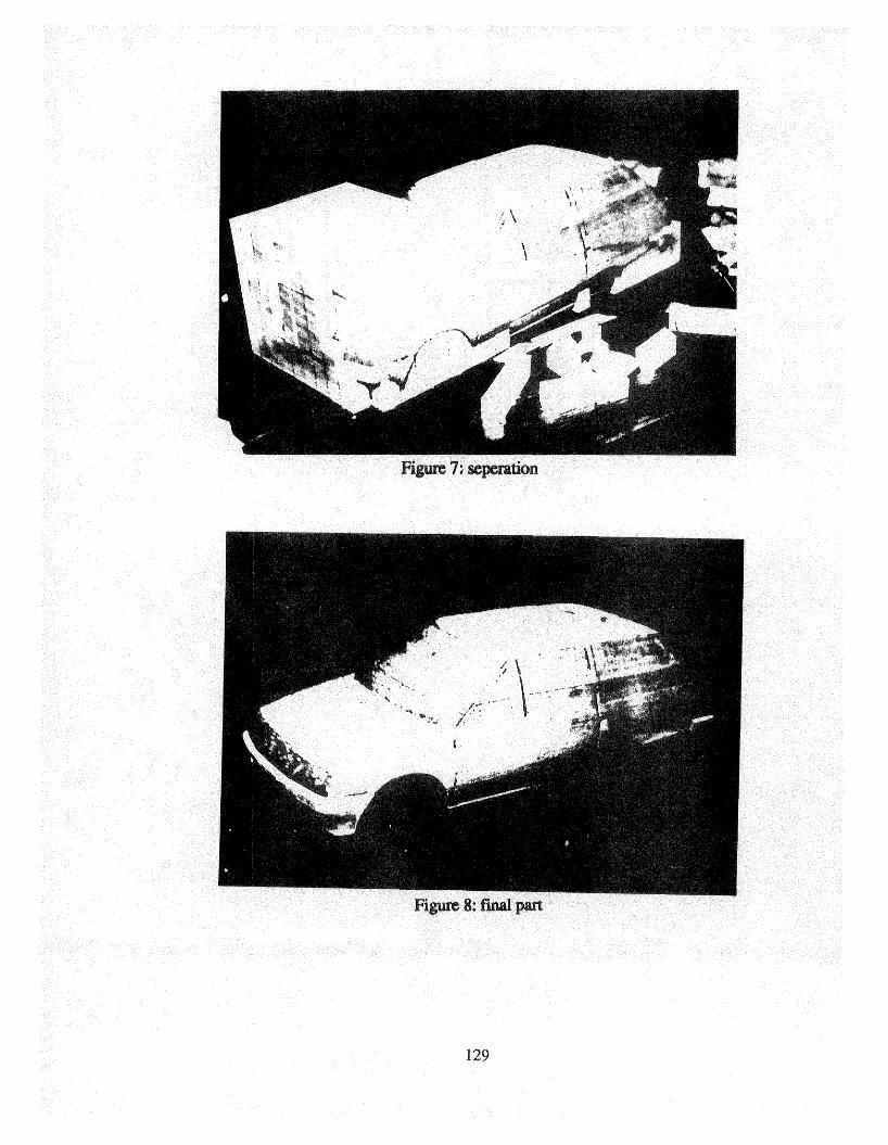

Figure 9: WMSlice
130