laminar solutions, inc. avionics bay mark ii
TRANSCRIPT

1
Laminar Solutions, Inc. Avionics Bay Mark II
Teams 9-13
Michael Andrews Coleby Friedland
Uday Pansara Eric L. Pheterson
Tim Philipp
September 26, 2011

2
System Requirements The avionics bay is one of the most complex subsystems of any integrated rocket. All electronics and control features essential to successful flight and landing are stored within this modular section. The main components to be housed inside the avionics bay include:
• One minialt W/D altimeter • One 9V battery power source (for the minialt) • Two Linoo Fly DV cameras (one mounted for horizon feed and one mounted for
terrestrial feed) • Wires connected from the minialt to the exterior of the bay with connector
terminals to connect to each E-Match The main challenges of the avionics bay are design-related; similar manufacturing processes can be applied regardless of the arrangement of components contained within the bay. The bay must be designed with structural resilience as a priority to prevent the damage of electrical components. The previous avionics bay from previous years (designated the “Mark I” design) was analyzed for strengths, weakness, opportunities, and threats before designing the “Mark II” avionics bay configuration.
Figure 1: The Expected Rocket Trajectory (The Blue Dots Indicate Fuse Ignitions)
Components PerfectFlite Minialt W/D Altimeter The altimeter provided for this subsystem is the minialt W/D version from PerfectFlite. Using a simple pressure sensor, it determines the pressure altitude at any given time
3
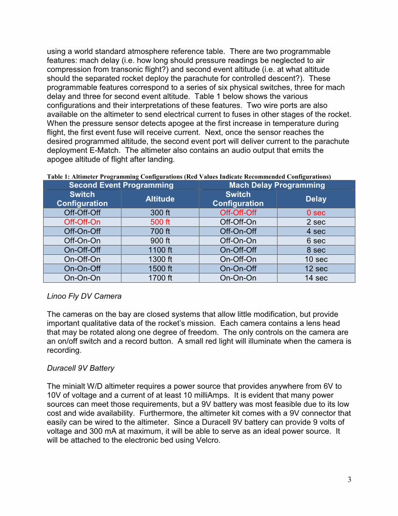
using a world standard atmosphere reference table. There are two programmable features: mach delay (i.e. how long should pressure readings be neglected to air compression from transonic flight?) and second event altitude (i.e. at what altitude should the separated rocket deploy the parachute for controlled descent?). These programmable features correspond to a series of six physical switches, three for mach delay and three for second event altitude. Table 1 below shows the various configurations and their interpretations of these features. Two wire ports are also available on the altimeter to send electrical current to fuses in other stages of the rocket. When the pressure sensor detects apogee at the first increase in temperature during flight, the first event fuse will receive current. Next, once the sensor reaches the desired programmed altitude, the second event port will deliver current to the parachute deployment E-Match. The altimeter also contains an audio output that emits the apogee altitude of flight after landing. Table 1: Altimeter Programming Configurations (Red Values Indicate Recommended Configurations)
Second Event Programming Mach Delay Programming Switch
Configuration Altitude
Switch Configuration
Delay
Off-Off-Off 300 ft Off-Off-Off 0 sec Off-Off-On 500 ft Off-Off-On 2 sec Off-On-Off 700 ft Off-On-Off 4 sec Off-On-On 900 ft Off-On-On 6 sec On-Off-Off 1100 ft On-Off-Off 8 sec On-Off-On 1300 ft On-Off-On 10 sec On-On-Off 1500 ft On-On-Off 12 sec On-On-On 1700 ft On-On-On 14 sec
Linoo Fly DV Camera The cameras on the bay are closed systems that allow little modification, but provide important qualitative data of the rocket’s mission. Each camera contains a lens head that may be rotated along one degree of freedom. The only controls on the camera are an on/off switch and a record button. A small red light will illuminate when the camera is recording. Duracell 9V Battery The minialt W/D altimeter requires a power source that provides anywhere from 6V to 10V of voltage and a current of at least 10 milliAmps. It is evident that many power sources can meet those requirements, but a 9V battery was most feasible due to its low cost and wide availability. Furthermore, the altimeter kit comes with a 9V connector that easily can be wired to the altimeter. Since a Duracell 9V battery can provide 9 volts of voltage and 300 mA at maximum, it will be able to serve as an ideal power source. It will be attached to the electronic bed using Velcro.

4
There was some initial concern if a Velcro bond would hold the 9V battery during expected g-forces from launch and chute deployment. However, a similar attachment scheme is often used for the power sources of weather balloon experiments. When subjected to ascent, wind gusts, and the g-forces induced by parachute deployment once the balloon has ruptured, the power source remained attached and functional. For the scope of this rocket mission, similar g-forces are expected up to those encountered during weather balloon chute deployment. Other Electrical Components (Wires, Altimeter Button, and Splice Connectors) There are various other components connected to the altimeter via insulated wires. A switch must be connected to the altimeter via a wire port adjacent to the E-Match wire ports. A spring-loaded push button was chosen as the ideal switch for the Mark II bay (justification of the design can be found in “Mark II Design Improvements”). Also, splice connectors were chosen as the terminals to connect to fuses external to the avionics bay. By consulting the graphic of the connectors in Table 2, the functionality of the connectors is very intuitive. The light blue component is connected to the bay with the wire feeding through the cylindrical tube. The wire connected to the fuse is crimped by folding the dark blue connector. A plug is then formed with the dark blue connector that can be firmly connected to the other end of the light blue connector. A pack of red connectors were also used to distinguish different wires from each other.
Table 2: Avionics Bay Components
Linoo Fly DV Camera PerfectFlite miniAlt/WD
Altimeter (Top)
PerfectFlite miniAlt/WD
Altimeter (Top)
Quick Splice Connector with
Male Disconnector
Spring-Loaded Push Button 9V Battery

5
Mark I Design Overview The Mark I design was in operation during Fall of 2010 and met the same design requirements mentioned above and can be seen in Figure 1. The two cameras were mounted opposite each other on a plastic board which held the altimeter at top, cameras at bottom and power switch with the battery opposite the altimeter. The exterior had holes to access the camera and altimeter power switches, as well as viewing ports for the cameras. The Mark I design achieved a ground view via an angled mirror with a drag-reducing cover.
Figure 2: Mark I Design, Interior Front & Back and Exterior Views (Quarter is Used for Scale)
Although it fulfilled all system requirements, the need for several improvements arose during missions. The exterior holes used to turn on the components as well as provide ports for cameras resulted in drag penalties. Furthermore, none of these holes were for the altimeter; i.e., no effort was made to ensure continuous airflow to the minialt pressure sensor. The design also lacked lean/six sigma analysis, evident by the unused portions of the electronics bed and wasteful lengths of unused wires. Mark II Improvements All drawbacks realized in the previous section have been resolved in the Mark II revision. The new design utilizes a push button to power cycle the altimeter, replacing

6
the cumbersome switch and significantly reducing the necessary hole to turn on the altimeter. The wasted space along the length of the avionics bay has been removed to save 2½ inches from the overall length, an 18% length reduction. The horizontal camera view port is no longer a hole, but a window covered with a molded polycarbonate sheet, which allows visibility without drag penalties (see Figure [#]). The support tubes attaching the mounting plate to the threaded rods are now PVC which minimize cost and weight without compromising structural integrity. Finally, eight 1/16 inch holes have been added, circling the altimeter, to equalize internal pressure and offer the most accurate pressure altitude reading.
Figure 3: Comparison of Polycarbonate (Left) vs. Tape Window Ports (Note the Glare on the Tape Window)
Alternative Investigated Technologies Several other design improvements were considered but were abandoned due to feasibility and design constraints. An RF-controlled power switch was considered instead of a manual switch. This would have allowed reduced holes in the bay casing and conserved power, but wasn’t integrated into the Mark II configuration due to cost constraints. Efforts to integrate all power requirements of the altimeter and cameras to be met via a single power source were investigated, but ultimately rejected because the cameras could not be modified. An attempt was also made to place the cameras so that the switches lied perpendicular to the longitudinal motion of the rocket (with the possibility of g-forces tripping switches in mind), but the length of the cameras exceeded the rocket diameter and limited alignment options. Carbon fiber was also considered as a possible material, but the cost and training needed to manufacture molds exceeded constraints. Finally, half of a nose cone was considered as a possible terrestrial periscope instead of a fiberglass mold, but the team was advised that the Mark I periscope design produced no significant performance penalties.

7
Chosen Design The final design can be seen in Figures 4 and 5 below.
Figure 4: Interior Design
The interior layout of the Mark II revision is much like that of the Mark I. The most notable difference is the tighter packing of components and corresponding shortening of the electronic bed. Cameras are mounted opposite to each other on the mounting plate. A push button for the altimeter is located in the middle of the unit and lines up with an exterior hole for easy access. The altimeter and battery are mounted opposite of each other. The wiring connecting the battery, button, and altimeter is simplified by a hole drilled near the push button that gives a more direct route than wrapping cables around the side.
Figure 5: Exterior Design

8
The main features of the exterior are several holes and the periscope for the down viewing camera. The periscope for the downward camera is molded around the Mark I design (Figure 3 shows a simplified shape). A curved plastic window covers the view port of the horizontal facing camera. The remaining large holes are for access to the power button and cameras, and as such are not covered. Small holes were added around the altimeter to facilitate accurate data collection. Great attention will be made towards burr removal for any drilled holes. As shown in Figure 6, burrs can potentially skew the pressure altitude experienced and will result in incorrect data.
Figure 6: Case (a) Results in a Lower Pressure Reading, and Case (b) Results in a Greater Pressure Reading
Materials & Components The major design materials are detailed in Table 3. The list of masses of each component can be found in Table 5 of the Appendix. For the window, mounting plate, mirrors, electrical wire, PVC tubes, and threaded rod, more material than necessary was purchased. Several components were provided by the customer and cost is not given.

9
Table 3: Bill of Materials
Item Cost Source Clear Plastic Sheet (12”x12”) $1.98 Lowe’s Mirrors (Variety Pack) $1.99 Michael’s Electrical Wire (5 ft.) $1.55 Lowe’s PVC Tubing (5 ft.) $1.68 Lowe’s Eye Bolts (2x) $0.98 Lowe’s Threaded Rod (3 ft.) $1.82 Lowe’s Nuts (9x) $0.54 Lowe’s Push Button $2.19 Radio Shack Quick Splice Connector with Male Disconnector (2 Packs)
$4.38 Radio Shack
Blue Tube (54 mm diameter, 48” length) $23.95* Apogee Rockets Coupler (2x) $2.41* Apogee Rockets Bulkhead (2x) $5.30* Apogee Rockets Fiberglass Mirror Fitting $0.00* Aerodynamics Design Lab Linoo Fly DV Cameras (2) $399.96* Allied: Lock and Safe PerfectFlite minialt W/D Altimeter $79.95* PerfectFlite 9V Duracell Copper Top Battery $5.79* Radio Shack * denotes items that were provided by the lab $534.47 Total Cost $17.11 Total Purchases
Assembly The mounting plate, PVC tubes, and threaded rods are first cut to specified dimensions. Holes are drilled in the mounting plate so that the altimeter and push button can be screwed in. The threaded rods are inserted into the PVC and held in place with nuts. The tubes are then secured to the mounting plate with tape. An additional hole is drilled to run a wire from the battery to the button. The cameras are fixed to the plate with hot glue and the battery is attached with Velcro. The bulkheads are epoxied together from several layers of circular wood pieces, and positioned on the threaded rods with nuts. Eye-bolts are screwed into the bulkheads. The exterior is cut to length from body tube material. Couplers are glued into the ends, half of their length in and half out, and holes are drilled in order to give access to the electronics and views to the cameras. The hole for the horizon camera has a window formed from the same clear plastic that makes the mounting plate. The ground camera has a periscope glued onto the body tube over its hole. The periscope was formed by creating a fiberglass layup using the Mark I periscope as a mold. A mirror is glued into the periscope at a 45° angle, so that the camera sees straight down the rocket. The interior and exterior sections are attached by gluing the lower bulkhead to the coupler. This bulkhead then becomes part of the exterior unit, then the interior is slid up the threaded rods, the nuts are tightened, and the interior is attached to the exterior.

10
Operation
To ensure optimal performance from the the Mark II avionics bay proper inspection, installation, and extraction must be performed according to the instruction below. Pre-Flight Installation and Inspections:
1. Remove the interior electric bed from the external casing of the avionics bay in order to view the altimeter.
2. Program the altimeter for mach delay and second event altitude. a. The mach delay feature can be disabled since we are assuming
incompressible flow regimes (off-off-off switch configuration). b. For this size rocket and altitude level, it is recommended that parachute
deployment occur at 500 feet above sea level (off-off-on switch configuration).
3. Ensure that all wire connections for the altimeter, power button, and terminals are firmly secured.
4. Using a multimeter, check the voltage of the battery. If the voltage is below 7 volts replace the battery with a new 9V source bonded with Velcro. (Note: Steps 1-4 need not be performed for every launch, but only after considerable time has passed between launches or there is suspicion that components are not functioning correctly.
5. Connect the leads from each E- match their respective lead on each bulkhead using the splice connectors. The red connectors should be used for the apogee event and the blue connectors should be used for the second event.
6. Fit the avionics bay to the other rocket subsystems via the couplers. 7. Use a pin, pen, or pencil to push down the spring button to turn on the minialt
altimeter. 8. Use a similar utensil on each camera switch to power them on. 9. Initiate video recording by pressing ‘OK’ on each camera. Verify that the camera
is functioning by looking for a red light. 10. Perform all other subsystem procedures. 11. Launch the rocket.
Post Flight Data Extraction:
12. Recover the rocket after it has landed. 13. Initially inspect the avionics bay to see if any damages occurred that could have
skewed trajectory data. 14. Press the record button again BEFORE turning off each camera. Note: Failing to
press the record button post-flight will erase all visual data! 15. Listen to the series of beeps emitted by the altimeter in between ten-second
pauses. a. Each series of beeps corresponds to the value of each digit in the apogee
altitude (one beep for one, two beeps for two, R, nine beeps for nine, ten beeps for zero).

11
b. There will be a short pause between digit values. c. For example, if apogee occurs at 1250 ft, the following signal will be
heard: one beep, pause, two beeps, pause, five beeps, pause, ten beeps, ten-second pause, R
d. Record this apogee altitude twice to ensure it isn’t interpreted erroneously. 16. Connect the altimeter to a computer via the USB adapter provided in the
altimeter kit. Make sure that the computer has the required PerfectFlite software. 17. Upload the trajectory (altitude vs. time) data to the working computer. 18. Turn off the altimeter by pressing the push button.
Expected Performance The Mark II avionics bay performs several important tasks while the rocket is in flight. While on the launch rail prior to ignition, the altimeter will remain in a “resting state”, where no data will be recorded unless a pressure change resulting an 80 ft increase in elevation in the course of a fraction of a second. The on board flight computer will consequentially monitor the altimeter periodically to dynamically determine pressure altitude. At apogee, the pressure will begin to increase, the computer can then activate the first step of separation by triggering the lower e-match at peak altitude. The flight computer also triggers the second separation phase, parachute deployment, at the user-selected height. This enables the parachute to be activated in time to arrest the rocket’s fall and protect delicate parts while avoiding excessive displacement viadrifting. Secondary performance expectations are to record quality video at the horizontal and behind the rocket perspectives. This is useful for documenting and debriefing any rocket mission. Conclusion Laminar Solutions, Inc. is confident that the Mark II avionics bay provides unique design improvements as well as unprecedented manufacturing and operational data, for a fraction of the cost of competitor designs. This avionics bay was designed with the intent of accomplishing all mission objectives while simultaneously providing minimal contributions to weight, drag, and costs (such as material procurement and learning required). This can be evidenced by the reduction in length, efforts to successfully reduce drag by covering and reducing exterior holes, and reducing waste in the form of wires and excess electronics bed. The confidence in these design improvements stems from literature research, manufacturing prototypes, and advising.

12
Appendix
Figure 7: Gantt Chart of Avionics Specialty Efforts
Table 4: Miscellaneous Technical Parameters
Parameter Value Units Bay Length w/ Coupler 11.5 Inches Body Tube Outer Diameter 2.260 Inches Body Tube Thickness 0.125 Inches Coupler Outer Diameter 2.174 Inches Coupler Thickness 0.6 Inches Acrylic Plate Width 1.125 Inches Acrylic Plate Length 7.825 Inches Camera Window Area 1.0 Inches2 Device Access Diameter 0.5 Inches Mirror Area 1.0 Inches2
PVC Length 8.0 Inches Camera Allowance 0.25 Inches Battery Allowance 0.875 Inches Weight of Bay 0.91 Pounds Table 5: Weight Table
Component Weight (grams) Quantity Total Weight(grams) Camera 20.7 2 41.4
Body Tube and Couplers 86.6 1 86.6 Periscope 7.7 1 7.7
Mirror 2.9 1 2.9 Battery 49.1 1 49.1
Connector 2.6 4 10.4 Bulkheads 67.2 1 67.2
Cord 18.4 1 18.4 Plate-Button-Altimeter
System 55.1 1 55.1
Threaded Rod 48.5 1 48.5 Nut 3.2 8 25.6
419.0