l’invisibile vertical pivot system - usi interiorinvisibile-date...l’invisibile vertical pivot...
TRANSCRIPT

L’INVISIBILE VERTICAL PIVOT SYSTEM“FILO 10”
L’IN
VIS
IBIL
E V
ER
TIC
AL
PIV
OT S
YSTEM
“FI
LO 1
0”
- In
stal
lati
on a
nd A
ssem
bly
Inst
ruct
ions
- pag
. 1 o
f 16
Technical data, Installationand Assembly Instructions

L’IN
VIS
IBIL
E V
ER
TIC
AL
PIV
OT S
YSTEM
“FI
LO 1
0”
- In
stal
lati
on a
nd A
ssem
bly
Inst
ruct
ions
- pag
. 2 o
f 16

L’IN
VIS
IBIL
E V
ER
TIC
AL
PIV
OT S
YSTEM
“FI
LO 1
0”
- In
stal
lati
on a
nd A
ssem
bly
Inst
ruct
ions
- pag
. 2 o
f 16
L’IN
VIS
IBIL
E V
ER
TIC
AL
PIV
OT S
YSTEM
“FI
LO 1
0”
- In
stal
lati
on a
nd A
ssem
bly
Inst
ruct
ions
- pag
. 3 o
f 16
L’IN
VIS
IBIL
E V
ER
TIC
AL
PIV
OT S
YSTEM
“FI
LO 1
0”
- In
stal
lati
on a
nd A
ssem
bly
Inst
ruct
ions
- pag
. 4 o
f 16

L’IN
VIS
IBIL
E V
ER
TIC
AL
PIV
OT S
YSTEM
“FI
LO 1
0”
- In
stal
lati
on a
nd A
ssem
bly
Inst
ruct
ions
- pag
. 4 o
f 16
L’IN
VIS
IBIL
E V
ER
TIC
AL
PIV
OT S
YSTEM
“FI
LO 1
0”
- In
stal
lati
on a
nd A
ssem
bly
Inst
ruct
ions
- pag
. 5 o
f 16

L’IN
VIS
IBIL
E V
ER
TIC
AL
PIV
OT S
YSTEM
“FI
LO 1
0”
- In
stal
lati
on a
nd A
ssem
bly
Inst
ruct
ions
- pag
. 6 o
f 16

L’IN
VIS
IBIL
E V
ER
TIC
AL
PIV
OT S
YSTEM
“FI
LO 1
0”
- In
stal
lati
on a
nd A
ssem
bly
Inst
ruct
ions
- pag
. 6 o
f 16
L’IN
VIS
IBIL
E V
ER
TIC
AL
PIV
OT S
YSTEM
“FI
LO 1
0”
- In
stal
lati
on a
nd A
ssem
bly
Inst
ruct
ions
- pag
. 7 o
f 16
Materiale occorrente in cantiere (non fornito)
LIVELLA
4 MOLLE DA MURATORE
CAZZUOLA
FILO A PIOMBO
4 MORSETTI
CEMENTO A PRESA RAPIDA
2 qUADROTTI (RIghE) DI ALLUMINIOLEVEL
Necessary materials on site (not supplied)
(2 ALUMINIUM RULES50 X 50 X CLEAR WIDHT)
4 MANSONRY SPRINGS
4 CLAMPS
TROWEL
PLUMBLINE
QUICK-SETTINGS CEMENT
The installation sequences of the Vertical Pivot System FILO 10 totally share those of the Vertical Pivot System.
L’IN
VIS
IBIL
E V
ER
TIC
AL
PIV
OT S
YSTEM
“FI
LO 1
0”
- In
stal
lati
on a
nd A
ssem
bly
Inst
ruct
ions-
pag
. 8 o
f 16
Installation and Assembly Instruction
1 Posizionare il Nucleo-Telaio in alluminio, completo di triangoli in MDF e distanziali di irrigidimento, sui piedi di livello a pavimento, allineandolo attentamente ai testimoni di intonaco e procedere alla messa a piombo, come illustrato.
Presenza dei fori architettonici-porta sulle pareti grezze.
Testimoni di intonaco.
Piede di livello (a pavimento finito) nei fori architettonici-porta.
Quota pavimento finito (tracciata sulle pareti grezze).
2 Fissare il Nucleo-Telaio in alluminio alla parete con schiuma poliuretanica o cemento rapido in alcuni punti, per dare solidità al prodotto, ed attenderne la solidifica-zione.
IN QUESTA FASE È VIETATO SMONTARE I DISTANZIALI DI IRRIGIDIMENTO DAL
NUCLEO-TELAIO IN ALLUMINIO.
Fasi di montaggio per versione MURATURA
SITUAZIONE CANTIERE
2
MATERIALE FORNITO IN DOTAZIONE
75 6
9 10 11
3
1: guarnizione 2: serratura (predisposta per chiave, cilindro o nottolino, su richiesta) 3: braccio inferiore in ottone MAB AC2 completo di viti (già inserito nel pannello) 4: riscontro perno superiore MAB AC 8 completo di viti (già inserito nel pannello) 5: n° 2 viti per serratura 6: viti per perni inferiori e superiori, inferiore e superiore 7: piletta MAB AC 246 (o equivalente) 8: Dima completa 9: Braccio perno superiore MAB AC 8 10: piastrina (quantità in base all'altezza- solo per versione cartongesso) 11: pompa MAB a pavimento (se richiesta).Versione a 2 ante in aggiunta al materiale standard 1: pozzetto a molla in ottone di diam. 8 2: n° 1 piastrina per catenaccio 3: n° 2 catenacci a leva completi di viti.
8 1 2 3
41
LATO FILOMURO
TESTIMONED’INTONACO
1
3
4
2
L’IN
VIS
IBIL
E V
ER
TIC
AL
PIV
OT S
YSTEM
“FI
LO 1
0”
- In
stal
lati
on a
nd A
ssem
bly
Inst
ruct
ions-
pag
. 8 o
f 16
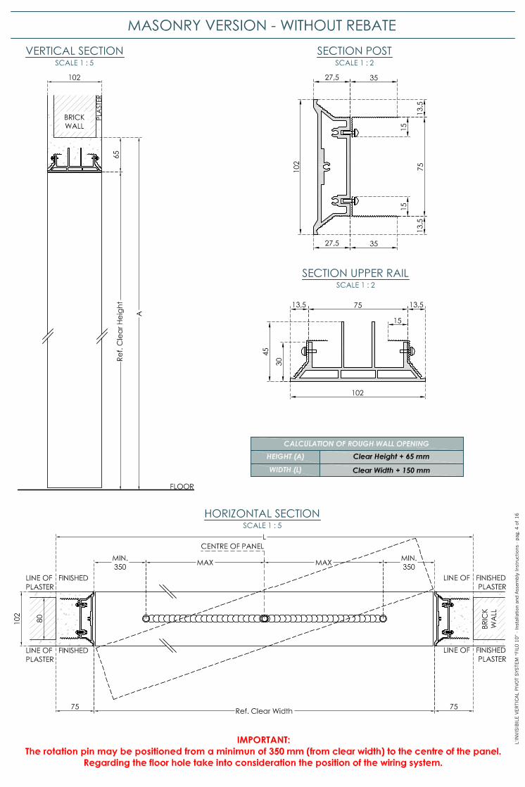
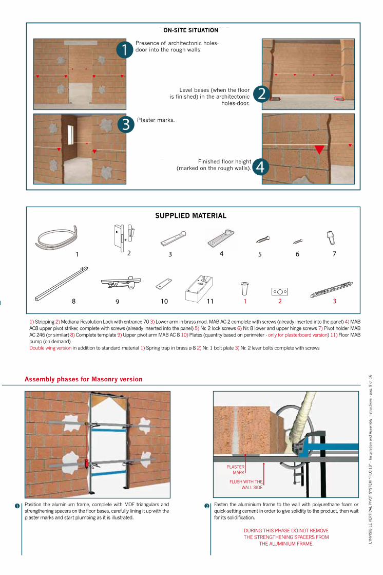
1) Stripping 2) Mediana Revolution Lock with entrance 70 3) Lower arm in brass mod. MAB AC 2 complete with screws (already inserted into the panel) 4) MAB AC8 upper pivot striker, complete with screws (already inserted into the panel) 5) Nr. 2 lock screws 6) Nr. 8 lower and upper hinge screws 7) Pivot holder MAB AC 246 (or similar) 8) Complete template 9) Upper pivot arm MAB AC 8 10) Plates (quantity based on perimeter - only for plasterboard version) 11) Floor MAB pump (on demand) Double wing version in addition to standard material 1) Spring trap in brass ø 8 2) Nr. 1 bolt plate 3) Nr. 2 lever bolts complete with screws
Presence of architectonic holes-door into the rough walls.
Plaster marks.
Finished floor height(marked on the rough walls).
Level bases (when the flooris finished) in the architectonic
holes-door.
SUPPLIED MATERIAL
Assembly phases for Masonry version
L’IN
VIS
IBIL
E V
ER
TIC
AL
PIV
OT S
YSTEM
“FI
LO 1
0”
- In
stal
lati
on a
nd A
ssem
bly
Inst
ruct
ions
- pag
. 9 o
f 16
Position the aluminium frame, complete with MDF triangulars and strengthening spacers on the floor bases, carefully lining it up with the plaster marks and start plumbing as it is illustrated.
Fasten the aluminium frame to the wall with polyurethane foam or quick-setting cement in order to give solidity to the product, then wait for its solidification.
DURING THIS PHASE DO NOT REMOVETHE STRENGTHENING SPACERS FROM
THE ALUMINIUM FRAME.
PLASTERMARK
FLUSH WITH THE WALL SIDE
ON-SITE SITUATION
3 Procedere al riempimento, con cemento, degli spazi vuoti fra il Nucleo-Telaio in alluminio e la parete grezza, prestando la massima attenzione a non causare movimenti del Nucleo-Telaio in alluminio e attendere almeno 12 ore.
4 Procedere alla rasatura delle pareti rispettando scrupo-losamente il filo d’intonaco determinato dal Nucleo-Telaio stesso.
ATTENZIONE: SORMONTARE IL FILO D’INTONACO CON LA RASATURA COMPROMETTE IL MOVIMENTO DEL
PANNELLO PORTA ED ANNULLA L’EFFETTO PLANARITÀ. ESEGUITE QUESTE OPERAZIONI, SMONTARE I
DISTANZIALI DI IRRIGIDIMENTO, AVENDO CURA DI STUCCARE I RELATIVI FORI.
1 Il posizionamento in orditura metallica del Nucleo-Telaio in alluminio è possibile solamente se la stessa è priva di lastre in cartongesso. Posizionare il Nucleo-Telaio in alluminio sui piedi di livello a pavimento, allineandolo attentamente ai testimoni di cartongesso e procedere alla messa a piombo, come illustrato.
3
2 Iniettare la schiuma poliuretanica in alcuni punti per dare solidità al prodotto e attenderne la solidificazione.
IN QUESTA FASE E' VIETATO SMONTARE I DISTANZIALI E
GLI ANGOLARI DI IRRIGIDIMENTO DEL NUCLEO-TELAIO IN ALLUMINIO
4 Posizionare la lastra in cartongesso svasata avvitandola all'apposito profilo fissato sul Nucleo-Telaio in alluminio. Sagomare l'appoggio della lastra in carton-gesso in corrispondenza delle lastrine di fissaggio fra telaio ed orditura metallica.(vedi anche illustrazione successiva)
Fasi di montaggio per versione CARTONGESSO
TESTIMONE INCARTONGESSO
Posizionare le piastrine , fornite a corredo nel kit, sul Nucleo-Telaio in alluminio, fissandole correttamente all'orditura metallica senza alterare la precedente messa in posa del telaio.Il fissaggio deve avvenire sia sul lato a filo muro che sul lato opposto.
LATO FILOMURO
L’IN
VIS
IBIL
E V
ER
TIC
AL
PIV
OT S
YSTEM
“FI
LO 1
0”
- In
stal
lati
on a
nd A
ssem
bly
Inst
ruct
ions
- pag
. 10 o
f 16
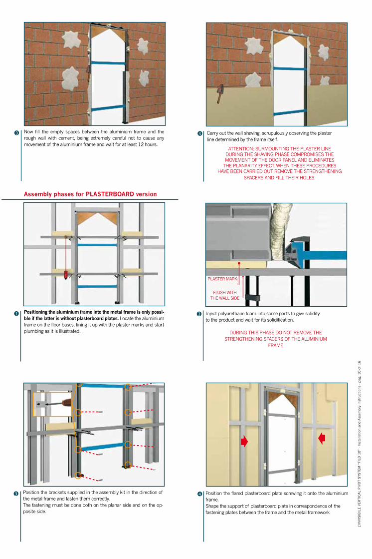
Now fill the empty spaces between the aluminium frame and the rough wall with cement, being extremely careful not to cause any movement of the aluminium frame and wait for at least 12 hours.
Positioning the aluminium frame into the metal frame is only possi-ble if the latter is without plasterboard plates. Locate the aluminium frame on the floor bases, lining it up with the plaster marks and start plumbing as it is illustrated.
Inject polyurethane foam into some parts to give solidityto the product and wait for its solidification.
DURING THIS PHASE DO NOT REMOVE THESTRENGTHENING SPACERS OF THE ALUMINIUM
FRAME
Position the brackets supplied in the assembly kit in the direction of the metal frame and fasten them correctly.The fastening must be done both on the planar side and on the op-posite side.
Position the flared plasterboard plate screwing it onto the aluminium frame.Shape the support of plasterboard plate in correspondence of the fastening plates between the frame and the metal framework
Carry out the wall shaving, scrupulously observing the plasterline determined by the frame itself.
ATTENTION: SURMOUNTING THE PLASTER LINEDURING THE SHAVING PHASE COMPROMISES THEMOVEMENT OF THE DOOR PANEL AND ELIMINATES
THE PLANARITY EFFECT. WHEN THESE PROCEDURESHAVE BEEN CARRIED OUT REMOVE THE STRENGTHENING
SPACERS AND FILL THEIR HOLES.
Assembly phases for PLASTERBOARD version
PLASTER MARK
FLUSH WITHTHE WALL SIDE

5 Applicare la garza autoadesiva per cartongesso e il relativo stucco nella sede della svasatura.
6 Procedere alla rasatura della parete.
ATTENZIONE: SORMONTARE IL FILO D’INTONACO CON LA LASTRA DI CARTONGESSO COMPROMETTE
IL MOVIMENTO DEL PANNELLO PORTA ED ANNULLA L’EFFETTO PLANARITÀ.
IN QUESTA FASE SMONTARE I DISTANZIALI DI IRRIGIDIMENTO, AVENDO CURA DI STUCCARE I
RELATIVI FORI.
2 Togliere il tappo di protezione del traverso superiore del Nucleo-Telaio in alluminio e fissare con cura il perno di rotazione Mab AC 8, fornito in dotazione nel kit di montaggio.
1 Procedere alla pulitura del Nucleo-Telaio in alluminio con carta vetrata o paglietta in acciaio, per togliere eventuali schizzi di cemento E PROCEDERE ALLA COLORAZIONE CON TEMPERA O ALTRI PRODOTTI, facendo attentamente riferimento alla scheda tecnica del prodotto utilizzato.
IL RISULTATO FINALE CHE SI DEVE OTTENERE È LA COMPLETA INVISIBILITÀ DEL NUCLEO-TELAIO IN
ALLUMINIO NELLA PARETE
4 A: Toccare con le estremità della dima le basi dei montanti in alluminio (verificando che non ci siano impedimenti o anomalie di filo intonaco-alluminio).B: Portare la dima con l’angolare di appoggio in battuta di riferimento.
3 Con riferimento al lato planare della porta adagiare la dima sul pavimento vicino alla base dei montanti di alluminio.
Fasi conclusive montaggio per versione MURATURA/CARTONGESSO
MODALITÀ UTILIZZO DIMA
A B
L’IN
VIS
IBIL
E V
ER
TIC
AL
PIV
OT S
YSTEM
“FI
LO 1
0”
- In
stal
lati
on a
nd A
ssem
bly
Inst
ruct
ions
- pag
. 11 o
f 16
L’IN
VIS
IBIL
E V
ER
TIC
AL
PIV
OT S
YSTEM
“FI
LO 1
0”
- In
stal
lati
on a
nd A
ssem
bly
Inst
ruct
ions
- pag
. 10 o
f 16
Apply the self-stick gauze for plasterboard and its filler into the flare seat. Carry out the wall shaving.
ATTENTION: SURMOUNTING THE PLASTER LINE DURING THESHAVING PHASE COMPROMISES THE MOVEMENT OF THE DOOR PANEL AND ELIMINATES THE PLANARITY EFFECT. WHEN THESE
PROCEDURES HAVE BEEN CARRIED OUT REMOVE THESTRENGTHENING SPACERS AND FILL THEIR HOLES.
Now clean the aluminium frame with sandpaper or steel wool in order to erase any possible spot of cement and THEN START COLOURING WITH TEMPERA OR OTHER PRODUCT carefully referring to the tech-nical sheet pertaining to the used product
THE END RESULT TO BE OBTAINED IS THE TOTALINVISIBILITY OF THE FRAME WITHIN THE WALL.
With reference to the planar side, lay the template lay the template on the floor near the base of the aluminium supports.
ALUMINIUM SUPPORTS
A: Touch the bases of the aluminium supports with the ends of the template (making sure there are no impediments or anomalies in the line of plaster-aluminium).B: Place the template with the ledge reference support corner.
Remove the protective cap from the upper rail of the aluminium frame and carefully fasten the rotation pin MAB AC 8 supplied in the assem-bly kit.
Final assembly phases for plasterboard/ masonry versions
Assembly template (dima)

5 A: Inserire nel suo alloggio la rondella direzionale con foro Ø 6.B: Forare attraverso la rondella direzionale con punta Ø 6 per 35mm di profondità.
6 Rimuovere la dima togliendo dal suo alloggio la rondella direzionale con foro Ø 6.
8 Registrare se necessario la piletta di rotazione in ottone, mod. MAB AC-246 (o equivalente).A: La base del perno di rotazione (registrabile) nel suo movimento non deve toccare la tazza di rotazione (potrebbe provocare frizioni). Distanza tassativa mm. 2.
7 Forare il pavimento per mm. 35 con fresa a tazza “punto di centraggio Ø 6, fresa di Ø 22”.
10 Iniettare il sigillante nel foro pavimento, posizionando la “tazza di rotazione”.
9 A: Rimuovere la vite superiore .B: Registrare la vite di appoggio inferiore. C: Riposizionare la vite superiore sino al bloccaggio della vite di appoggio inferiore.
A B
AB
PERNO DI ROTAZIONE
TAZZA DI ROTAZIONE
mm. 2 tassativo
A
MODALITÀ UTILIZZO PILETTA
A B C
L’IN
VIS
IBIL
E V
ER
TIC
AL
PIV
OT S
YSTEM
“FI
LO 1
0”
- In
stal
lati
on a
nd A
ssem
bly
Inst
ruct
ions
- pag
. 12 o
f 16
A: Insert in its place the direction washer (hole diam. 6)B: Pierce through the direction washer with drill diam. 6 for 35 mm depth
Drill the floor to a depth of 35 mm with cup cutter: centring point Ø 6, cutter of Ø 22.
If necessary adjust the brass pivot holder, Mod. MABAC-246 (or similar).A: The base of the rotation pivot (adjustable) must nottouch the rotation cup in its movement (it could causefriction). Exact distance 2 mm.
ROTATION PIVOT
mm 2 exact
ROTATION CUP
Inject sealer (or other compound) into the floor hole,positioning the rotation cup
A: Remove the upper screw.B: Adjust the lower support screw.C: Reposition the upper screw until the lower supportscrew is blocked.
Remove the template by removing the direction washer from its place (diameter hole 6)
Pivot holder assembly

11 A: Riposizionare la dima priva della rondella direzionale Ø 6.B:Controllare (infilandolo) che il perno di rotazione cada esattamente nella tazza di rotazione (che rimane mobile il tempo necessario alla solidificazione del sigillante).
14
Togliere il perno di rotazione.
Riposizionare delicatamente il perno di rotazione ed attendere la solidificazione del sigillante.
13 Rimuovere completamente la dima.
15 Per posizionare il pannello in legno agire sul perno superiore MAB AC 8, facendolo rientrare.
16 Riposizionare il pannello nell'alloggiamento inferiore e allinearlo alla parte superiore facendo rientrare il perno superiore all'interno del pannello stesso.
A B
12
MODALITÀ MONTAGGIO PANNELLO
L’IN
VIS
IBIL
E V
ER
TIC
AL
PIV
OT S
YSTEM
“FI
LO 1
0”
- In
stal
lati
on a
nd A
ssem
bly
Inst
ruct
ions
- pag
. 13 o
f 16
L’IN
VIS
IBIL
E V
ER
TIC
AL
PIV
OT S
YSTEM
“FI
LO 1
0”
- In
stal
lati
on a
nd A
ssem
bly
Inst
ruct
ions
- pag
. 12 o
f 16
A: Reposition the template before the direction washer Ø 6.B: Check (by inserting) that the rotation pivot falls exactlyinto the rotation cup (which remains mobile until the sealerhardens).
Remove the rotation pivot
Remove the template completely. Carefully reposition the rotation pivot and wait until the sealer hardens.
In order to position the wooden panel act on the upper pivot MAB AC 8 making it retract.
Position the panel in the lower seat and line it up with the upper part making the upper pivot retract into the panel.
Pivot holder assembly
Panel Assembly

17 Se necessario, uniformare gli sfiori laterali del pannello sul Nucleo-Telaio in alluminio agendo sul riscontro perno superiore.
8
18 Se necessario, uniformare gli sfiori laterali del pannello sul Nucleo-Telaio in alluminio agendo sul braccio inferiore in ottone.
19 Dopo aver pulito accuratamente il pannello di legno, pennellarlo uniformemente, su ambo i lati e in costa, con un fondo, ad es. cementite (quando fornito grezzo). Prima di procedere all'applicazione del pre trattamento e/o trattamento prescelti fare attentamente riferimento alla scheda tecnica del prodotto utilizzato. Procedere quindi alla finitura del pannello sempre su ambo i lati e in costa.
ATTENZIONE: EVENTUALI ACCUMULI DI VERNICE NEI BORDI POTREBBERO ALTERARE L'UNIFORMITA' DEGLI SFIORI E COMPROMETTERE ILMOVIMENTO
DEL PANNELLO-PORTA.
ATTENZIONE: FARE ATTENZIONE A NON OSTRUIRE I FORI POSIZIONATI SUL LATO SUPERIORE DEL PANNELLO, QUANDO PRESENTI, DURANTE LE OPERAZIONI DI VERNICIATURA E/O MESSA IN
OPERA.
Consigli utili in merito a coloranti e metodologie da usare nel caso di rivestimento dell’anta;
- Per cristalli a specchio utilizzare silicone neutro;- Per ceramica utilizzare silicone acetico;- Per carta da parati stendere collante e carta su ambo i lati usando collante tradizionale
ATTENZIONE: L'APPLICAZIONE DI VERNICI, COLLE, SILICONI, CARTE DA PARATI SOLO SU UN LATO DEL PANNELLO-PORTA COMPROMETTE LA PLANARITA' DEL PANNELLO STESSO. E' NECESSARIO PROCEDERE ALLA FINITURA/TRATTAMENTO DEL PANNELLO SEMPRE SU AMBO I LATI E IN COSTA (per chiarimenti e/o supporto in fase di finitura rivolgersi al nostro Ufficio Tecnico).
Ogni attenzione è stata riservata a questi documenti prima della stampa. Tuttavia a causa della continua evoluzione tecnologica ed essendo costantemente impegnati sul fronte dello sviluppo e miglioramento della nostra gamma prodotti, ci riserviamo il diritto di modificare senza preavviso le specifiche di qualsiasi prodotto.
L’IN
VIS
IBIL
E V
ER
TIC
AL
PIV
OT S
YSTEM
“FI
LO 1
0”
- In
stal
lati
on a
nd A
ssem
bly
Inst
ruct
ions
- pag
. 14 d
i 16
If necessary, level the panel lateral grazing surface on the aluminium frame by working on the upper hinge.
If necessary, level the panel lateral grazing surface on the aluminium frame acting on the lower hinge.
After carefully cleaning the wooden panel, uniformly paint it on both sides and on the edge, with a white base layer (if supplied raw). Before proceedings with the chosen preliminary treatment carefully refer to the technical sheet pertaining to the used product, THEN FINISH THE PANEL ONCE AGAIN ON BOTH SIDEDS AND ON THE EDGE.
ATTENTION: ANY POSSIBLE ACCUMULATION OFVARNISH ON THE EDGE MAY ALTER THE UNIFORMITY
OF THE GRAZING SURFACE AND DAMAGE THEMOVEMENT OF THE DOOR PANEL
BE CAREFUL DO NOT OBSTRUCT THE HOLES LOCATED ON THE TOP OF THE PANEL, IF PRESENTS, DURING THE PAINTING AND /
OR INSTALLATION PHASES.

NOTES
L’IN
VIS
IBIL
E V
ER
TIC
AL
PIV
OT S
YSTEM
“FI
LO 1
0”
- In
stal
lati
on a
nd A
ssem
bly
Inst
ruct
ions
- pag
. 15 d
i 16
L’IN
VIS
IBIL
E V
ER
TIC
AL
PIV
OT S
YSTEM
“FI
LO 1
0”
- In
stal
lati
on a
nd A
ssem
bly
Inst
ruct
ions
- pag
. 14 d
i 16

L’INVISIBILE byPORTARREDO srlVia C. Besana, 144011 Argenta (Fe) - ItalyTel. +39.0532.800.960Fax [email protected]
ISO 9001
Socio del GBC Italia
These documents are the property of Portarredo s.r.l. and are protected by Italian as well as international laws, treaties and agreements on intellectual property. They may not be copied, reproduced, translated or transcribed in any form whatsoever, in whole or in part, without the prior written authorisation of Portarredo s.r.l.
Maximum attention has been paid to these documents before printing. However, because of continuous technological development and since we are constantly engaged in the development and improvement of our product range, we reserve the right to modify specifications of any product without prior notice.
L’IN
VIS
IBIL
E V
ER
TIC
AL
PIV
OT S
YSTEM
“FI
LO10”
- Ju
ly 2
013 - G
IBM
TIN
G01.0
1
L’IN
VIS
IBIL
E V
ER
TIC
AL
PIV
OT S
YSTEM
“FI
LO 1
0”
- In
stal
lati
on a
nd A
ssem
bly
Inst
ruct
ions
- pag
. 16 d
i 16
Associated
Certified Company
Partner of GBC Italy