ladder diagram
DESCRIPTION
ElecsTRANSCRIPT
LADDER DIAGRAM
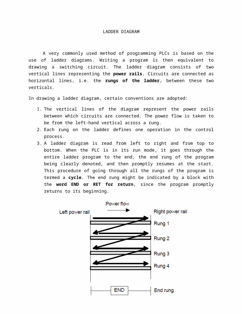
A very commonly used method of programming PLCs is based on the use of ladder diagrams. Writing a program is then equivalent to drawing a switching circuit. The ladder diagram consists of two vertical lines representing the power rails. Circuits are connected as horizontal lines, i.e. the rungs of the ladder, between these two verticals.
In drawing a ladder diagram, certain conventions are adopted:
1. The vertical lines of the diagram represent the power rails between which circuits are connected. The power flow is taken to be from the left-hand vertical across a rung.
2. Each rung on the ladder defines one operation in the control process.3. A ladder diagram is read from left to right and from top to bottom. When the PLC is in its run
mode, it goes through the entire ladder program to the end, the end rung of the program being clearly denoted, and then promptly resumes at the start. This procedure of going through all the rungs of the program is termed a cycle. The end rung might be indicated by a block with the word END or RET for return, since the program promptly returns to its beginning.
4. Each rung must start with an input or inputs and must end with at least one output. The term input is used for a control action, such as closing the contacts of a switch, used as an input to the PLC. The term output is used for a device connected to the output of a PLC, e.g. a motor.
5. Electrical devices are shown in their normal condition. Thus a switch which is normally open until some object closes it, is shown as open on the ladder diagram. A switch that is normally closed is shown closed.
6. A particular device can appear in more than one rung of a ladder. For example, we might have a relay which switches on one or more devices. The same letters and/or numbers are used to label the device in each situation.
7. The inputs and outputs are all identified by their addresses, the notation used depending on the PLC manufacturer. This is the address of the input or output in the memory of the PLC.

Basic Example
In drawing ladder diagrams
the names of the associated variable or addresses of each element are appended to its symbol.

Notation: (a) Mitsubishi, (b) Siemens, (c) Allen-Bradley, (d) Telemecanique
Logic Functions
There are many control situations requiring actions to be initiated when a certain combination of conditions is realised.
AND
Figure shows a situation where an output is not energised unless two, normally open, switches are both closed. Switch A and switch B have both to be closed, which thus gives an AND logic situation. electrical circuit where an output is energized
An example of an AND gate is an interlock control system for a machine tool so that it can only be operated when the safety guard is in position and the power switched on.
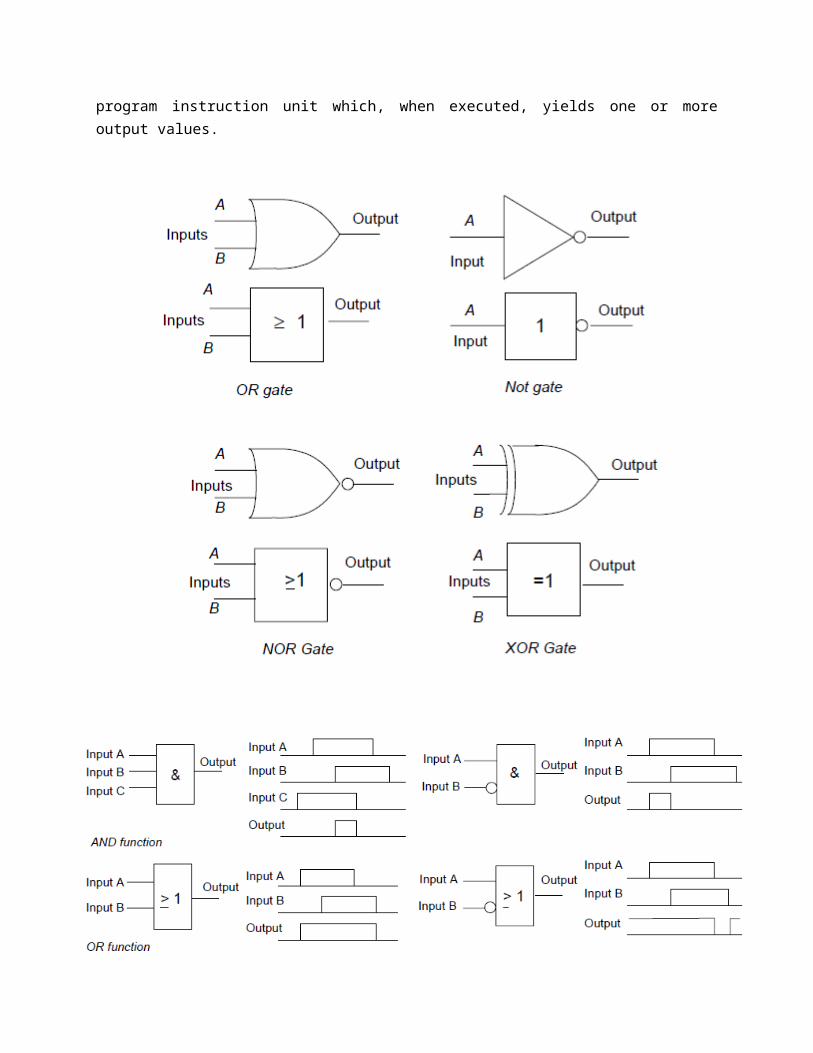
OR
When switch A or B, both normally open, are closed. Alternative paths provided by vertical paths from the main rung of a ladder diagram, i.e. paths in parallel, represent logical OR operations.

An example of an OR gate control system is a conveyor belt transporting bottled products to packaging where a deflector plate is activated to deflect bottles into a reject bin if either the weight is not within certain tolerances or there is no cap on the bottle.
NOT
When there is an input to the switch, it opens and there is then no current in the circuit. This illustrates a NOT gate in that there is an output when there is no input and no output when there is an input. The gate is sometimes referred to as an inverter.
An example of a NOT gate control system is a light that comes on when it becomes dark, i.e. when there is no light input to the light sensor there is an output.

NAND
Suppose we follow an AND gate with a NOT gate. The consequence of having the NOT gate is to invert all the outputs from the AND gate. An alternative, which gives exactly the same results, is to put a NOT gate on each input and then follow that with OR.
An example of a NAND gate control system is a warning light that comes on if, with a machine tool, the safety guard switch has not been activated and the limit switch signalling the presence of the workpiece has not been activated.
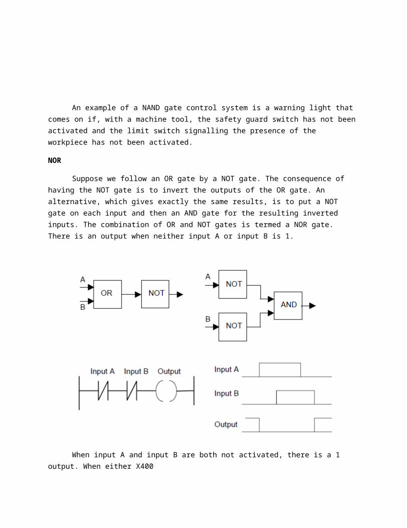
NOR
Suppose we follow an OR gate by a NOT gate. The consequence of having the NOT gate is to invert the outputs of the OR gate. An alternative, which gives exactly the same results, is to put a NOT gate on each input and then an AND gate for the resulting inverted inputs. The combination of OR and NOT gates is termed a NOR gate. There is an output when neither input A or input B is 1.

When input A and input B are both not activated, there is a 1 output. When either X400
or X401 are 1 there is a 0 output.
XOR
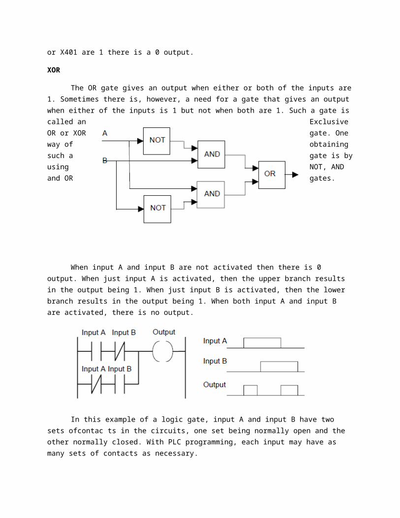
The OR gate gives an output when either or both of the inputs are 1. Sometimes there is, however, a need for a gate that gives an output when either of the inputs is 1 but not when both are 1. Such a gate is called an Exclusive OR or XOR gate. One way of obtaining such a gate is by using NOT, AND and OR gates.
When input A and input B are not activated then there is 0 output. When just input A is activated, then the upper branch results in the output being 1. When just input B is activated, then the lower branch results in the output being 1. When both input A and input B are activated, there is no output.
In this example of a logic gate, input A and input B have two sets ofcontac ts in the circuits, one set being normally open and the other normally closed. With PLC programming, each input may have as many sets of contacts as necessary.
There are often situations where it is necessary to hold an output energised, even when the input ceases. A simple example of such a situation is a motor which is started by pressing a push button switch. Though the switch contacts do not remain closed, the motor is required to continue running until a stop push button switch is pressed. The term latch circuit is used for the circuit used to carry out such an operation. It is a self-maintaining circuit in that, after being energised, it maintains that state until another input is received.
As an illustration of the application of a latching circuit, consider a motor controlled by stop and start push button switches and for which one signal light must be illuminated when the power is applied to the motor and another when it is not applied.
With ladder diagrams, there can be more than one output connected to a contact. When the input contacts close both the coils give outputs.
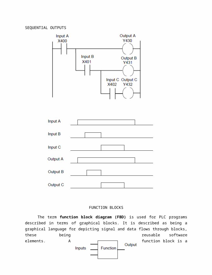
SEQUENTIAL OUTPUTS

FUNCTION BLOCKS
The term function block diagram (FBD) is used for PLC programs described in terms of graphical blocks. It is described as being a graphical language for depicting signal and data flows through blocks, these being reusable software elements. A function block is a program instruction unit which, when executed, yields one or more output values.

Ladder diagram and equivalent functional block diagram
Consider the development of a function block diagram and ladder diagram for an application in which a pump is required to be activated and pump liquid into a tank when the start switch is closed, the level of liquid in the tank is below the required level and there is liquid in the reservoir from which it is to be pumped.
What is required is an AND logic situation between the start switch input and a sensor input which is on when the liquid in the tank is below the required level. We might have a switch which is on until the liquid is at the required level. These two elements are then in an AND logic situation with a switch indicating that there is liquid in the reservoir. Suppose this switch gives an input when there is liquid.
PROGRAM EXAMPLES
1) A signal lamp is required to be switched on if a pump is running and the pressure is satisfactory, or if the lamp test switch is closed.
2) A valve which is to be operated to lift a load when a pump is running and either the lift switch is operated or a switch operated indicating that the load has not already been lifted and is at the bottom of its lift channel.
3) Consider a system where there has to be no output when any one of four sensors gives an output, otherwise there is to be an output.