labvolt series datasheet€¦ · en 120 v - 60 hz 05/2018. antenna ... the antenna training and...
TRANSCRIPT
LabVolt Series
Datasheet
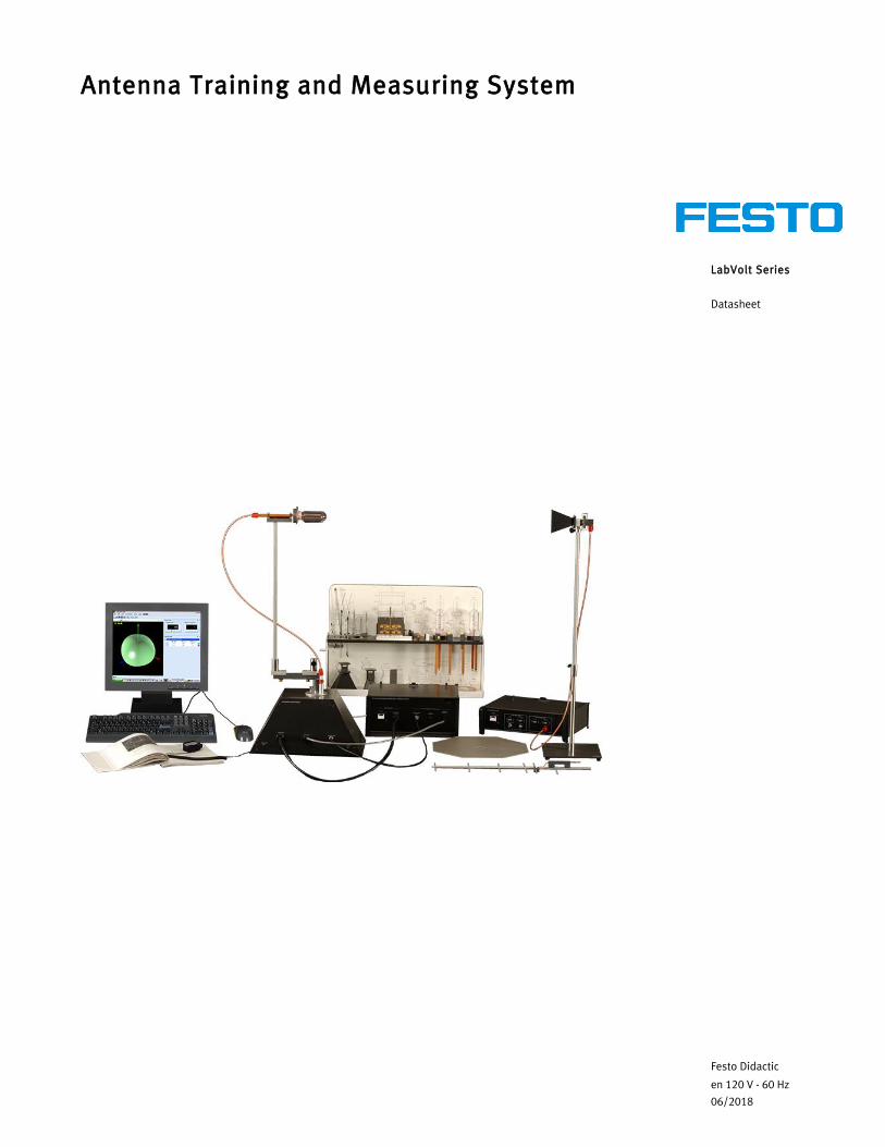
Antenna Training and Measuring System
Festo Didactic
en 120 V - 60 Hz
06/2018
Antenna Training and Measuring System, LabVolt Series
2 © Festo Didactic
Table of ContentsGeneral Description_______________________________________________________________________2Antennas________________________________________________________________________________5Features & Benefits _______________________________________________________________________7List of Equipment_________________________________________________________________________8List of Manuals___________________________________________________________________________8Table of Contents of the Manual(s) __________________________________________________________8Additional Equipment Required to Perform the Exercises ________________________________________8Optional Equipment_______________________________________________________________________9Optional Manual(s) _______________________________________________________________________9Equipment Description ____________________________________________________________________9Optional Equipment Description __________________________________________________________ 17
General DescriptionThe Antenna Training and Measuring System (ATMS), Model 8092, provides teachers and students with training materials for hands-on experimentation on antennas in the 1 GHz and 10 GHz bands. A convenient and powerful antenna measuring system, the ATMS can also be utilized by design and research teams.
The complete Antenna Training and Measuring System includes a set of 1 GHz antennas, a set of 10 GHz antennas, an RF Generator, a receiving system, and the Data Acquisition and Management Software for
Antennas (LVDAM-ANT), a user-friendly software operating under the Microsoft® Windows™ environment. The receiving system consists of a rotating Antenna Positioner linked to a Data Acquisition Interface connected to the USB port of a personal computer.
The system is designed for low power operation, both in the 1 GHz and 10 GHz bands (specifically at 915 MHz and at 10.5 GHz), allowing measurements of antenna characteristics in these bands. The data acquisition interface controls the antenna positioner and acquires the received antenna signal.
The LVDAM-ANT package provides a toolbox for controlling antenna rotation and data acquisition, as well as for displaying measured antenna characteristics in the E and the H planes. It also includes algorithms for estimating beamwidth and antenna gain from measurements or from external data.
The ATMS is a self-contained, stand-alone system that does not require other microwave equipment. However, optional antennas, a two element phasing kit, and a set of RCS demonstration accessories can be added to the ATMS in order to enhance the scope of experimentation on antennas and reflectors. These pieces of optional equipment are listed and described in the Optional Equipment and Optional Equipment Description sections of this data sheet. Furthermore, the ATMS is compatible with the 10.5 GHz Microwave Technology Training System, Model 8090. The VSWR Meter and the Power Meter of the Microwave Technology Training System, along with microwave components such as the slotted line, the Gunn oscillator, attenuators, and couplers, can be put to use for various creative laboratory projects.

Antenna Training and Measuring System, LabVolt Series
© Festo Didactic 3
Figure 1. The E-plane and the H-plane patterns are acquired separately. These patterns can be plotted on a polar graph (as shown in figure) or a Cartesian graph (see Figure 2).
Figure 2. E- and H-plane patterns of an helical antenna plotted on a Cartesian coordinate graph.
Figure 3. The acquired E- and H-plane patterns can be displayed simultaneously on a tri-dimensional (3D) display (shown in figure: dipole antenna pattern).
Antenna Training and Measuring System, LabVolt Series
4 © Festo Didactic
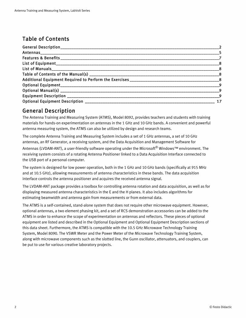
Figure 4. The acquired E- and H-plane patterns can be displayed simultaneously on a tri-dimensional (3D) display (shown in figure: helical antenna pattern).
Figure 5. The E- and H-plane patterns can also be combined to produce a full 3D radiation pattern (shown in figure: dipole antenna pattern).

Antenna Training and Measuring System, LabVolt Series
© Festo Didactic 5
AntennasThe ATMS provides a great variety of 1-GHz and 10-GHz antennas. With the exception of the horn- and waveguide-type antennas, connection to each antenna is made through an SMA connector. The 1-GHz and 10-GHz antennas available in the ATMS are listed below:
1-GHz Antennas:
• Dipoles (λ/2, λ, 3λ/2)• Folded Dipole• Folded Dipole with Balun• Monopole (over ground plane)• Drooping Monopole• Loops (circular, square, lozenge)• Fixed Yag• Adjustable Yagi
10-GHz Antennas:
• Open-Ended Waveguide• Slotted Waveguide (single and multi-slots)• Horns (small and large aperture)• Helical (right-hand and left-hand circular polarization)• Patch (rectangular, parallel-fed array, series-fed array)
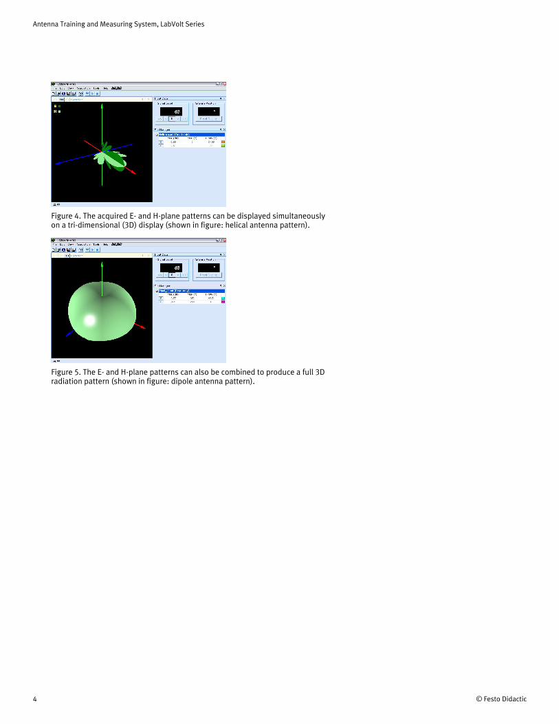
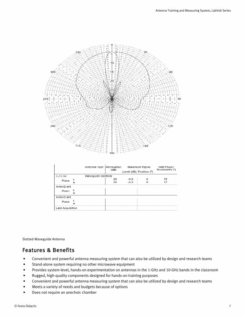
The following figures show polar plots of the radiation patterns of the folded dipole and slotted-waveguide antennas, obtained using the ATMS:
Antenna Training and Measuring System, LabVolt Series
6 © Festo Didactic
Folded Dipole Antenna
Antenna Training and Measuring System, LabVolt Series
© Festo Didactic 7
Features & Benefits• Convenient and powerful antenna measuring system that can also be utilized by design and research teams• Stand-alone system requiring no other microwave equipment• Provides system-level, hands-on experimentation on antennas in the 1-GHz and 10-GHz bands in the classroom• Rugged, high-quality components designed for hands-on training purposes• Convenient and powerful antenna measuring system that can also be utilized by design and research teams• Meets a variety of needs and budgets because of options• Does not require an anechoic chamber
Slotted-Waveguide Antenna

Antenna Training and Measuring System, LabVolt Series
8 © Festo Didactic
• Devices and components fabricated from electroless-plated brass to standard X-band waveguide dimensions• Waveguide flanges are joined by precision quick fasteners, allowing rapid assembly and disassembly of microwave
circuits• Estimated program duration: 45 hours
List of Equipment
Qty DescriptionModel number
1 RF Generator __________________________________________________________________________ 9505-001 Antenna Positioner _____________________________________________________________________ 9506-001 Data Acquisition Interface / Power Supply __________________________________________________ 9507-301 Horn Antenna, Small Aperture ____________________________________________________________ 9535-A02 Horn Antenna, Large Aperture ____________________________________________________________ 9550-002 Helical Antenna, Right-Hand Circular Polarization ____________________________________________ 9551-001 Helical Antenna, Left-Hand Circular Polarization _____________________________________________ 9552-001 Patch Antennas ________________________________________________________________________ 9553-001 Slotted-Waveguide Antenna ______________________________________________________________ 9554-001 Open-Ended Waveguide Antenna _________________________________________________________ 9555-001 Yagi Antenna __________________________________________________________________________ 9560-001 Wire Antennas _________________________________________________________________________ 9561-001 Cables and Accessories _________________________________________________________________ 9594-101 Waveguide Accessories _________________________________________________________________ 9594-A01 Antenna Support _______________________________________________________________________ 9595-001 Storage Module ________________________________________________________________________ 9598-00
List of Manuals
DescriptionManual number
Antenna Fundamentals (Student Manual) ______________________________________________________ 30857-00Antenna Fundamentals (Instructor Guide) _____________________________________________________ 30857-10Data Acquisition and Management Software (User Guide) ________________________________________ 30857-E0
Table of Contents of the Manual(s)Antenna Fundamentals (Student Manual) (30857-00)• 1-1 Radiation Pattern of a λ/2 Dipole at 1 GHz• 1-2 Radiation Pattern of an Open Waveguide at 10 GHZ• 1-3 Gain of Pyramidal Horn Antennas
• 1-4 Experiments with λ/2, λ, and 3λ/2 Dipoles• 1-5 Half Wave Folded Dipole Antennas and Impedance Transformation with Baluns• 2-1 Monopole Antennas• 2-2 Loop Antennas• 2-3 Circular Polarization and Helical Antennas• 2-4 Parasitic Array (Yagi-Uda) Antennas• 3-1 Antenna Arrays: The Slot Antenna• 3-2 Microstrip Technology: The Rectangular Patch Antenna• 3-3 Microstrip Planar Array Antennas
Additional Equipment Required to Perform the Exercises

Antenna Training and Measuring System, LabVolt Series
© Festo Didactic 9
1 Refer to the Computer Requirements in the System Specifications section of this datasheet if the computer is to be provided by the end-user.2 Optional product training. Price provided on demand. For details and options, contact [email protected] Required instead of the conventional Antenna Positioner, Model 9506-0, when using the optional RCS Demonstration Accessories, Model 9594-B.4 Requires the optional Antenna Positioner, RCS Ready, Model 9506-A, instead of the conventional Antenna Positioner, Model 9506-0.
Qty DescriptionModel number
1 Personal Computer _____________________________________________________________________ 8990-001 Training on Antenna Fundamentals, 0.6 day ________________________________________________ 30857-TF
Optional Equipment
Qty DescriptionModel number
1 Antenna Positioner, RCS Ready __________________________________________________________ 9506-A01 Directional Coupler, 1 GHz _______________________________________________________________ 9529-001 Multi-Beam Array Antenna _______________________________________________________________ 9556-002 Log-Periodic Antenna ___________________________________________________________________ 9562-001 Two-Element Phasing Kit ________________________________________________________________ 9563-001 RCS Demonstration Accessories _________________________________________________________ 9594-B01 Parabolic Reflector _____________________________________________________________________ 9596-00
Optional Manual(s)
Qty DescriptionModel number
1 Antenna Training and Measuring System (Manuals on CD-ROM) _______________________________ 30857-A01 The Multi-Beam Array Antenna (Student Manual) ___________________________________________ 33458-001 Two Element Phasing Kit Instructions (User Guide) __________________________________________ 35166-E0
Equipment Description
RF Generator 9505-00
The RF Generator contains two independent generators capable of producing a CW or 1 kHz square wave AM modulated RF signal at 915 MHz and 10.5 GHz. Each generator has a push-button switch for turning RF power on and off, a LED that flashes on and off when RF power is turned
on, and an SMA output connector. The oscillator in the 915 MHz generator can be tuned from 700 to 1200 MHz via an external tuning voltage input. All outputs are fully protected against short-circuits and misconnections. The RF Generator is self-powered and has a standard unregulated dc power bus to supply power to other compatible modules through its top panel connector. The unit beeps when RF power is turned on to help avoid interference and to warn students in the laboratory that RF power is emitted.
SpecificationsParameter Value
Power Requirement
Current 1 A
1
2
3
4
Antenna Training and Measuring System, LabVolt Series
10 © Festo Didactic
Parameter Value
Service Installation Standard single-phase ac outlet
Unregulated DC Output (Power Bus) +25 V typ. – 1 A max.; -25 V typ. – 1 A max.; +11 V typ. – 1 A max.
1 GHz RF Power Output
Impedance 50 Ω
Power Level +3 dBm (typical); 0 dBm (minimum)
10 GHz RF Power Output
Impedance 50 Ω
Power Level +10 dBm (typical)
1 GHz Tuning Voltage Input
Voltage Range 0-10 V
Frequency Range 700-1200 MHz
Protection
AC Line Input Circuit breaker
Unregulated DC Power Bus Circuit breaker
Physical Characteristics
Dimensions (H x W x D) 112 x 330 x 300 mm (4.4 x 13.0 x 11.8 in)
Net Weight 6.1 kg (13.4 lb)
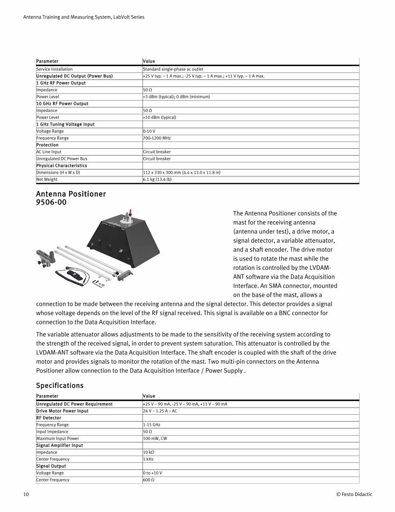
Antenna Positioner 9506-00
The Antenna Positioner consists of the mast for the receiving antenna (antenna under test), a drive motor, a signal detector, a variable attenuator, and a shaft encoder. The drive motor is used to rotate the mast while the rotation is controlled by the LVDAM-ANT software via the Data Acquisition Interface. An SMA connector, mounted on the base of the mast, allows a
connection to be made between the receiving antenna and the signal detector. This detector provides a signal whose voltage depends on the level of the RF signal received. This signal is available on a BNC connector for connection to the Data Acquisition Interface.
The variable attenuator allows adjustments to be made to the sensitivity of the receiving system according to the strength of the received signal, in order to prevent system saturation. This attenuator is controlled by the LVDAM-ANT software via the Data Acquisition Interface. The shaft encoder is coupled with the shaft of the drive motor and provides signals to monitor the rotation of the mast. Two multi-pin connectors on the Antenna Positioner allow connection to the Data Acquisition Interface / Power Supply .
SpecificationsParameter Value
Unregulated DC Power Requirement +25 V – 90 mA, -25 V – 90 mA, +11 V – 90 mA
Drive Motor Power Input 24 V – 1.25 A – AC
RF Detector
Frequency Range 1-15 GHz
Input Impedance 50 Ω
Maximum Input Power 100 mW, CW
Signal Amplifier Input
Impedance 10 kΩ
Center Frequency 1 kHz
Signal Output
Voltage Range 0 to +10 V
Center Frequency 600 Ω

Antenna Training and Measuring System, LabVolt Series
© Festo Didactic 11
Parameter Value
Physical Characteristics
Dimensions (H x W x D) 260 x 385 x 250 mm (10.2 x 15.2 x 9.8 in)
Net Weight 10.2 kg (22.4 lb)
Data Acquisition Interface / Power Supply 9507-30
The Data Acquisition Interface links the Antenna Positioner with the personal computer that runs the LVDAM-ANT software. The link to the computer is achieved through a USB port connector mounted on the rear panel of the module. The Data Acquisition Interface converts the received signal coming from the
Antenna Positioner into a digital signal which can be used by the computer. It also routes the shaft encoder signals coming from the Antenna Positioner to the computer and provides the signals required to control the drive motor and the variable attenuator in the Antenna Positioner. A BNC connector and a multi-pin connector allow connection of the Data Acquisition Interface to the Antenna Positioner.
Manual
DescriptionManual number
Data Acquisition and Management Software (User Guide) ________________________________________ 30857-E0
SpecificationsParameter Value
Power Requirements
Current 1.5 A
Service Installation Standard single-phase ac outlet
Data Acquisition Interface
Analog Signal Input Voltage Range 0 to +2.5 V
Analog Signal Input Impedance 1 MΩ
Power Supply
Unregulated DC Power Bus Output +25 V typ. – 1 A max.; -25 V typ. – 1 A max.; +11 V typ. – 1 A max.
Drive Motor Power Output 24 V – 1.5 A – AC
Computer RequirementsA currently available personal computer running under one of the following operating systems: Windows® 7 or
Windows® 8.
Physical Characteristics
Dimensions (H x W x D) 167 x 330 x 300 mm (6.6 x 13.0 x 11.8 in)
Net Weight 8.5 kg (18.8 lb)

Antenna Training and Measuring System, LabVolt Series
12 © Festo Didactic
Horn Antenna, Small Aperture 9535-A0
The Horn Antenna, Small Aperture is a WR90 waveguide-type pyramidal horn antenna.
SpecificationsParameter Value
Antenna
Gain 13.8 dB
Frequency 10.525 GHz
Horn Antenna, Large Aperture 9550-00
The Horn Antenna, Large Aperture, Model 9550, is a WR90 waveguide-type pyramidal horn antenna.
SpecificationsParameter Value
Antenna
Gain 16.7 dB
Frequency 10.525 GHz

Antenna Training and Measuring System, LabVolt Series
© Festo Didactic 13
Helical Antenna, Right-Hand Circular Polarization 9551-00
The Helical Antenna, Right-Hand Circular Polarization is an helical antenna with SMA connector. The antenna is protected with a plexiglas dome.
SpecificationsParameter Value
Antenna
Gain 13.6 dB
Frequency 10.525 GHz
Axial Ratio 1.08
Helical Antenna, Left-Hand Circular Polarization 9552-00
The Helical Antenna, Left-Hand Circular Polarization is an helical antenna with SMA connector. The antenna is protected with a plexiglas dome.
SpecificationsParameter Value
Antenna
Gain 13.6 dB
Frequency 10.525 GHz
Axial Ratio 1.08
Patch Antennas 9553-00
The Patch Antennas set consists of three microstrip patch antennas with SMA connector that operate at a frequency of 10.525 GHz.

Antenna Training and Measuring System, LabVolt Series
14 © Festo Didactic
SpecificationsParameter Value
Antenna Gain
Patch (Rectangular) 7.7 dB
Patch (Series-Fed Array) 13.0 dB
Patch (Parallel-Fed Array) 14.0 dB
Antenna Frequency 10.525 GHz
Slotted-Waveguide Antenna 9554-00
The Slotted-Waveguide Antenna is a light-weight, small-size WR90 waveguide-type slotted antenna. The slot antenna is of the "standing wave array" type. The array is terminated by a short circuit at the end of the waveguide.
SpecificationsParameter Value
Antenna
Gain 13.2 dB
Frequency 10.525 GHz
Open-Ended Waveguide Antenna 9555-00
The Open-Ended Waveguide Antenna is of the WR90 type.
SpecificationsParameter Value
Antenna
Gain TBE
Frequency 10.525 GHz

Antenna Training and Measuring System, LabVolt Series
© Festo Didactic 15
Yagi Antenna 9560-00
The Yagi Antenna is a six-element Yagi-Uda parasitic-array antenna with SMA connector.
SpecificationsParameter Value
Antenna
Gain TBE
Frequency 1 GHz
Wire Antennas 9561-00
The Wire Antennas is a kit that consists of an active element and a set of parasitic elements which can be assembled to obtain various types of antennas (e.g. Yagi antenna, loop antenna, folded-dipole antenna, dipole antenna).
SpecificationsParameter Value
Antenna Gain
Dipole (λ/2) 1.9 dB
Folded Dipole with Balun 2.1 dB
Monopole (Over Ground Plane) 2.5 dB
Drooping Monopole 1.6 dB
Circular Loop 2.9 dB
Square Loop 2.9 dB
Lozenge Loop 2.9 dB
Cables and Accessories 9594-10
The Cables and Accessories package contains the various cables and accessories required to perform the exercises in the program training manuals. The accessories package contains the following parts: three different lengths of coaxial cables terminated with BNC connectors ,

Antenna Training and Measuring System, LabVolt Series
16 © Festo Didactic
whip, pigtail, and folded dipole antennas, BNC T-connectors, resistive loads with BNC connectors, headset. These accessories come in a convenient plastic storage case.
Waveguide Accessories 9594-A0
The Waveguide Accessories kit contains the accessories required when using the horn- and waveguide-type antennas of the ATMS. The kit includes quick-lock fasteners, waveguide-to-coaxial cable adapters (SMA connector), a waveguide plastic holder, a waveguide short-circuit, and copper tape to modify the
characteristics of the slotted waveguide and patch antennas.
Antenna Support 9595-00
The Antenna Support is used as a mount for the fixed (transmitting) antenna of the ATMS. It comes with different adapters to mount different types of antennas.
Storage Module 9598-00
The Storage Module consists of a storage cabinet for storing equipment included in the Antenna Training and Measuring System, Model 8092.

Antenna Training and Measuring System, LabVolt Series
© Festo Didactic 17
Optional Equipment Description
Personal Computer (Optional) 8990-00
The Personal Computer consists of a desktop computer running under
Windows® 10. A monitor, keyboard, and mouse are included.
SpecificationsParameter Value
Power Requirements
Current 2 A
Service Installation Standard single-phase ac outlet
Antenna Positioner, RCS Ready (Optional) 9506-A0
This variant of the Antenna Positioner is provided with an auxiliary RF input coupled to an RF signal detector. These additional components are required when the ATMS is used with the optional RCS Demonstration Accessories, Model 9594-B, to measure and observe the near-field or far-field relative Radar Cross Section (RCS) of reflecting objects (targets).
RCS patterns of targets with different shapes are acquired, displayed, and stored using the LVDAM-ANT software the same way as antenna radiation patterns are. The ATMS and RCS Demonstration Accessories allow quasi-monostatic and bi-static RCS measurements to be performed.
The standard Antenna Positioner, Model 9506, is no longer required when the Antenna Positioner, Model 9506-A, is ordered.

Antenna Training and Measuring System, LabVolt Series
18 © Festo Didactic
5 The RCS demonstration accessories are required in order to perform RCS measurements.
A switch on the front panel of the Antenna Positioner allows selection between the RF input mounted on the base of the rotating mast and the auxiliary RF input.
Additional Equipment Required to Perform the Exercises
Qty DescriptionModel number
1 RCS Demonstration Accessories _________________________________________________________ 9594-B0
SpecificationsParameter Value
Unregulated DC Power Requirement +25 V – 90 mA, -25 V – 90 mA, +11 V – 90 mA
Drive Motor Power Input 24 V – 1.25 A – AC
RF Detector
Frequency Range 1-15 GHz
Input Impedance 50 Ω
Maximum Input Power 100 mW, CW
Signal Amplifier Input
Impedance 10 kΩ
Center Frequency 1 kHz
Signal Output
Voltage Range 0 to +10 V
Impedance 600 Ω
Physical Characteristics
Dimensions (H x W x D) 260 x 385 x 250 mm (10.2 x 15.2 x 9.8 in)
Net Weight 10.2 kg (22.4 lb)
Directional Coupler, 1 GHz (Optional) 9529-00The Directional Coupler consists of an AtlanTecRF A2023-20 directional coupler used in different microwave and antenna training systems.
SpecificationsParameter Value
Directional Coupler
Type AtlanTecRF A2023-20
Frequency 1 GHz
Coupling 20 dB
Average Power 50 W
Directivity 23 dB
Insertion Loss 0.35 dB
RCS pattern of a small metal plate obtained using the ATMS.
5

Antenna Training and Measuring System, LabVolt Series
© Festo Didactic 19
Multi-Beam Array Antenna (Optional) 9556-00
The Multi-Beam Array Antenna (MBAA) is designed to operate in the X frequency band (8-12.4 GHz) and provides students with training in phased array antenna theory. It allows hands-on experimentation in Advanced antenna principles used in the fields of radar imagery as well as
satellite and space-diversity communication systems.
The MBAA uses a microstrip Rotman lens to modify the phase shifts to a linear array of radiating elements. The antenna beam can be steered to various discrete directions by manually switching the connection to one of the MBAA RF port connectors. The MBAA can also be operated with multiple beams (2) by using the included power combiner. The MBAA is mechanically designed to provide easy installation on the ATMS Antenna Positioner. The student manual included with the MBAA deals with the multi-beam array antenna theory and design, antenna beam characteristics, and beam combination effects.
Manual
DescriptionManual number
The Multi-Beam Array Antenna (Student Manual) _______________________________________________ 33458-00
Table of Contents of the Manual(s)
The Multi-Beam Array Antenna (Student Manual) (33458-00)• 1 Multi-Beam Array Antenna Operation• 2 MBAA Gain and Performance Evaluation
MBAA radiation pattern obtained using the ATMS when two beams are simultaneously excited.

Antenna Training and Measuring System, LabVolt Series
20 © Festo Didactic
• 3 MBAA Multi-Beam Operation
SpecificationsParameter Value
Frequency Range 8.0-12.4 GHz
Overall Array Gain (@ 10.5 GHz) 10-13 dB
Maximum Sidelobe Level -15 dB
Maximum VSWR 1.8
Polarization Horizontal
Scanning Range ±35°
Number of Beams 8
Beamwidth 6° ±1°
Physical Characteristics
Dimensions (H x W x D) 70 x 380 x 430 mm (2.8 x 15.0 x 16.9 in)
Net Weight 1.0 kg (2.2 lb)
Log-Periodic Antenna (Optional) 9562-00
The Log-Periodic Antenna is designed to familiarize students with the principles of frequency independent antennas. The nominal frequency range of the Log-Periodic Antenna is 700 to 3600 MHz, but it can be operated from 700 to 1200 MHz when used with the ATMS (by tuning the frequency of the ATMS 1-GHz RF Generator). The antenna can be mounted to the ATMS Antenna Positioner for either vertical or
horizontal polarization. When operating at frequencies other than the regular 915MHz, using a second Log-Periodic antenna for transmission will lead to better results. For full flexibility in experimenting with this antenna, it is recommended that two are used, one for transmission and one for reception.
SpecificationsParameter Value
Gain 7.0 dB (typically)
Maximum VSWR 2.0
Frequency Range 700-3600 MHz
H-Plane Beamwidth 100°
E-Plane Beamwidth 60°
Input Impedance 50 Ω
Front-to-Back Ratio
Minimum 5 dB
Typical 15 dB
Physical Characteristics
Dimensions (H x W x D) 73 x 287 x 192 mm (2.9 x11.3 x 7.6 in)
Net Weight 0.13 kg (0.28 lb)

Antenna Training and Measuring System, LabVolt Series
© Festo Didactic 21
6 Optional product training. Price provided on demand. For details and options, contact [email protected].
Two-Element Phasing Kit (Optional) 9563-00
The Two-Element Phasing Kit enables students to observe the effects of antenna phasing on the resulting antenna radiation pattern (combined radiation pattern). Different combined radiation patterns such as end-fire, broadside, and cardioid can be obtained. These can be measured, stored, and analyzed using the ATMS.
The Two Element Phasing Kit consists of an additional drooping monopole antenna (one is already included in the ATMS), an additional antenna mast with vertical mounting clips (one is already included in the ATMS), a power splitter/combiner, and a set of RF cables of different lengths. Phase shifts of 0, 90, and 180 degrees can be produced with the supplied RF cables. Other phase shifts can be produced by using RF cables having lengths that differ from those of the supplied RF cables.
Manual
DescriptionManual number
Two Element Phasing Kit Instructions (User Guide) ______________________________________________ 35166-E0
Additional Equipment Required to Perform the Exercises
Qty DescriptionModel number
1 Training on Two Element Phasing Kit Instructions, 0.1 day ____________________________________ 35166-TF
SpecificationsParameter Value
Operating Frequency 1 GHz
RF Cable Lengths
RF Cable Lengths 30.0 (11.8 in)
Two drooping monopole antennas installed on the ATMS Antenna Positioner ready for experimenting the effects of antenna phasing.
6

Antenna Training and Measuring System, LabVolt Series
22 © Festo Didactic
Parameter Value
35.4 cm (13.9 in)
40.8 cm (16.1 in)
Physical Characteristics
Dimensions (H x W x D) 73 x 287 x 192 mm (2.9 x11.3 x 7.6 in)
Net Weight 1.58 kg (3.4 lb)
RCS Demonstration Accessories (Optional) 9594-B0
The RCS Demonstration Accessories kit contains all the accessories required to measure the relative RCS pattern of targets using the ATMS. It includes targets of various shapes (small and large metal plates, cylinder, and prism-shaped target), a 2 m SMA cable, a fixed antenna support, and an antenna mounting pole.
Manual
DescriptionManual number
8092 Antenna Training and Measuring System (User Guide) ______________________________________ 85256-E0
ATMS ready to measure the RCS of a metal plate. Notice the connection of a second horn antenna to the auxiliary RF input of the optional Antenna Positioner, Model 9506-A

Antenna Training and Measuring System, LabVolt Series
© Festo Didactic 23
Parabolic Reflector (Optional) 9596-00
The Parabolic Reflector allows students to study the characteristics of the parabolic antenna, one of today's most widely used antennas, that finds applications in cellular telephony, satellite communications, radars, etc.
The Parabolic Reflector mainly consists of a parabolic reflector and a chassis. It allows a complete parabolic antenna to be assembled using the small-aperture horn antenna included in the ATMS. A mast included in the Parabolic Reflector allows the
assembled parabolic antenna to be installed on the ATMS Antenna Positioner. This mast also allows the parabolic antenna to be tilted 90° for either vertical or horizontal polarization.
SpecificationsParameter Value
Frequency Range 8.0-12.4 GHz
Gain (typical) 27 dB
H-Plane Beamwidth (@ 9.0 GHz) 6°
E-Plane Beamwidth (@ 9.0 GHz) 8°
Input Impedance 50 Ω
Physical Characteristics
Dimensions (H x W x D) 375 x 370 x 510 mm (14.8 x 14.6 x 20.1 in)
Net Weight 1.5 kg (3.3 lb)

Antenna Training and Measuring System, LabVolt Series
24 © Festo Didactic
Reflecting the commitment of Festo Didactic to high quality standards in product, design, development, production, installation, and service, our manufacturing and distribution facility has received the ISO 9001 certification.
Festo Didactic reserves the right to make product improvements at any time and without notice and is not responsible for typographical errors. Festo Didactic recognizes all product names used herein as trademarks or registered trademarks of their respective holders. © Festo Didactic Inc. 2018. All rights reserved.
Festo Didactic SE
Rechbergstrasse 373770 DenkendorfGermany
P. +49(0)711/3467-0F. +49(0)711/347-54-88500
Festo Didactic Inc.
607 Industrial Way WestEatontown, NJ 07724United States
P. +1-732-938-2000F. +1-732-774-8573
Festo Didactic Ltée/Ltd
675 rue du CarboneQuébec QC G2N 2K7Canada
P. +1-418-849-1000F. +1-418-849-1666
www.labvolt.com
www.festo-didactic.com