labview basics ii (development course manual).pdf
TRANSCRIPT

LabVIEWTM Basics II DevelopmentCourse Manual
Course Software Version 8.0October 2005 EditionPart Number 320629N-01
LabVIEW Development Course Manual
Copyright
© 1993–2005 National Instruments Corporation. All rights reserved. Under the copyright laws, this publication may not be reproduced or transmitted in any form, electronic or mechanical, including photocopying, recording, storing in an information retrieval system, or translating, in whole or in part, without the prior written consent of National Instruments Corporation.
In regards to components used in USI (Xerces C++, ICU, and HDF5), the following copyrights apply. For a listing of the conditions and disclaimers, refer to the USICopyrights.chm.
This product includes software developed by the Apache Software Foundation (http:/www.apache.org/). Copyright
© 1999 The Apache Software Foundation. All rights reserved.
Copyright © 1995–2003 International Business Machines Corporation and others. All rights reserved.
NCSA HDF5 (Hierarchical Data Format 5) Software Library and UtilitiesCopyright 1998, 1999, 2000, 2001, 2003 by the Board of Trustees of the University of Illinois. All rights reserved.
TrademarksNational Instruments, NI, ni.com, and LabVIEW are trademarks of National Instruments Corporation. Refer to the Terms of Use section on ni.com/legal for more information about National Instruments trademarks.
Other product and company names mentioned herein are trademarks or trade names of their respective companies.
Members of the National Instruments Alliance Partner Program are business entities independent from National Instruments and have no agency, partnership, or joint-venture relationship with National Instruments.
PatentsFor patents covering National Instruments products, refer to the appropriate location: Help»Patents in your software, the patents.txt file on your CD, or ni.com/legal/patents.

Worldwide Technical Support and Product Informationni.com
National Instruments Corporate Headquarters11500 North Mopac Expressway Austin, Texas 78759-3504 USA Tel: 512 683 0100
Worldwide Offices
Australia 1800 300 800, Austria 43 0 662 45 79 90 0, Belgium 32 0 2 757 00 20, Brazil 55 11 3262 3599, Canada 800 433 3488, China 86 21 6555 7838, Czech Republic 420 224 235 774, Denmark 45 45 76 26 00, Finland 385 0 9 725 725 11, France 33 0 1 48 14 24 24, Germany 49 0 89 741 31 30, India 91 80 51190000, Israel 972 0 3 6393737, Italy 39 02 413091, Japan 81 3 5472 2970, Korea 82 02 3451 3400, Lebanon 961 0 1 33 28 28, Malaysia 1800 887710, Mexico 01 800 010 0793, Netherlands 31 0 348 433 466, New Zealand 0800 553 322, Norway 47 0 66 90 76 60, Poland 48 22 3390150, Portugal 351 210 311 210, Russia 7 095 783 68 51, Singapore 1800 226 5886, Slovenia 386 3 425 4200, South Africa 27 0 11 805 8197, Spain 34 91 640 0085, Sweden 46 0 8 587 895 00, Switzerland 41 56 200 51 51, Taiwan 886 02 2377 2222, Thailand 662 278 6777, United Kingdom 44 0 1635 523545
For further support information, refer to the Additional Information and Resources appendix. To comment on National Instruments documentation, refer to the National Instruments Web site at ni.com/info and enter the info code feedback.

© National Instruments Corporation iii LabVIEW Development Course Manual
Contents
Student GuideA. Course Description ...............................................................................................viB. What You Need to Get Started .............................................................................viiC. Installing the Course Software..............................................................................viiD. Course Goals.........................................................................................................viiiE. Course Conventions ..............................................................................................ix
Lesson 1Common Design Techniques
A. Single Loop Architectures ....................................................................................1-2B. Parallelism ............................................................................................................1-6Exercise 1-1 Concept: Evaluate Parallelism..........................................................1-8C. Multiple Loop Architectures.................................................................................1-9D. Timing a Design Pattern .......................................................................................1-13
Lesson 2Communicating Among Multiple Loops
A. Variables ...............................................................................................................2-2B. Functional Global Variables .................................................................................2-11Exercise 2-1 Variables VI......................................................................................2-14C. Race Conditions ....................................................................................................2-23Exercise 2-2 Concept: Bank VI .............................................................................2-30D. Synchronizing Data Transfer ................................................................................2-33Exercise 2-3 Project: Queue Data..........................................................................2-37Exercise 2-4 Optional: Global Data Project ..........................................................2-52
Lesson 3Improving an Existing VI
A. Refactoring Inherited Code...................................................................................3-2Exercise 3-1 Project: Refactor...............................................................................3-5B. Typical Issues .......................................................................................................3-23Exercise 3-2 Concept: Typical Issues....................................................................3-27

Contents
LabVIEW Development Course Manual iv ni.com
Lesson 4Controlling the User Interface
A. VI Server Architecture..........................................................................................4-2B. Property Nodes .....................................................................................................4-3Exercise 4-1 Temperature Limit VI.......................................................................4-5C. Control References ...............................................................................................4-9Exercise 4-2 Set Plot Names .................................................................................4-13D. Invoke Nodes ........................................................................................................4-23Exercise 4-3 Front Panel Properties VI .................................................................4-24
Lesson 5Advanced File I/O Techniques
A. File Formats ..........................................................................................................5-2B. Binary Files...........................................................................................................5-5Exercise 5-1 Bitmap File Writer VI ......................................................................5-12C. TDM Files.............................................................................................................5-20Exercise 5-2 TDM Logger VI ...............................................................................5-32Exercise 5-3 TDM Query ......................................................................................5-47
Lesson 6Creating and Distributing Applications
A. LabVIEW Features for Project Development.......................................................6-2Exercise 6-1 Concept: LabVIEW Project Management Tools..............................6-5B. Preparing the Application .....................................................................................6-7C. Building the Application and Installer..................................................................6-8Exercise 6-2 Concept: Creating a Stand-Alone Application .................................6-10
Appendix AAdditional Information and Resources
Index
Course Evaluation

© National Instruments Corporation v LabVIEW Development Course Manual
Student Guide
Thank you for purchasing the LabVIEW Basics II: Development course kit. You can begin developing an application soon after you complete the exercises in this manual. This course manual and the accompanying software are used in the two-day, hands-on LabVIEW Basics II: Development course.
You can apply the full purchase of this course kit toward the corresponding course registration fee if you register within 90 days of purchasing the kit. Visit ni.com/training for online course schedules, syllabi, training centers, and class registration.
Note For course manual updates and corrections, refer to ni.com/info and enter the info code rdlvc2.
The LabVIEW Basics II: Development course is part of a series of courses designed to build your proficiency with LabVIEW and help you prepare for exams to become an NI Certified LabVIEW Developer and NI Certified LabVIEW Architect. The following illustration shows the courses that are part of the LabVIEW training series. Refer to ni.com/training for more information about NI Certification.
LabVIEW Intermediate I*
LabVIEW Intermediate II*
New User Experienced User Advanced User
LabVIEW AdvancedApplication Development
LabVIEW AdvancedApplication Development
Certified LabVIEWAssociate Developer Exam
Certified LabVIEWDeveloper Exam
Certified LabVIEWArchitect Exam
Skills tested:• LabVIEW application development expertise
Skills learned:• Modular application development• Structured design and development practices• Memory management and VI performance improvement
Skills learned:• Large application design• Code reuse maximization• Object-oriented programming in LabVIEW
Skills tested:• LabVIEW application development mastery
Skills tested:• LabVIEW environment knowledge
Skills learned:• LabVIEW environment navigation• Basic application creation using LabVIEW
Certifications
Courses
Hardware-Based Courses: • Data Acquisition and Signal Conditioning • Modular Instruments • Instrument Control • Machine Vision • Motion Control • LabVIEW Real-Time
*Core courses are strongly recommended to realize maximum productivity gains when using LabVIEW.
LabVIEW Basics I*
Skills learned:• LabVIEW environment navigation• Basic application creation using LabVIEW
LabVIEW Basics II*
BeginHere

Student Guide
LabVIEW Development Course Manual vi ni.com
A. Course DescriptionUse this manual to learn about LabVIEW programming concepts, techniques, features, VIs, and functions you can use to create test and measurement, data acquisition, instrument control, datalogging, measurement analysis, and report generation applications.
This course manual assumes that you are familiar with Windows, Macintosh, or UNIX; that you have experience writing algorithms in the form of flowcharts or block diagrams; and that you have taken the LabVIEW Basics I: Introduction course or have equivalent experience.
The course manual is divided into lessons, each covering a topic or a set of topics. Each lesson consists of the following:
• An introduction that describes the purpose of the lesson and what you will learn
• A description of the topics in the lesson
• A set of exercises to reinforce those topics
• A set of additional exercises to complete if time permits
• A summary that outlines important concepts and skills taught in the lesson
Several exercises in this manual use a plug-in multifunction data acquisition (DAQ) device connected to a DAQ Signal Accessory containing a temperature sensor, function generator, and LEDs.
Exercises that explicitly require hardware are indicated with an icon, shown at left. You also can substitute other hardware for those previously mentioned. For example, you can use another National Instruments DAQ device connected to a signal source, such as a function generator.

Student Guide
© National Instruments Corporation vii LabVIEW Development Course Manual
B. What You Need to Get StartedBefore you use this course manual, make sure you have all of the following items:
❑ Windows 2000 or later installed on your computer; this course is optimized for Windows XP
❑ Multifunction DAQ device configured as device 1 using Measurement & Automation Explorer (MAX)
❑ DAQ Signal Accessory, wires, and cable
❑ LabVIEW Professional Development System 8.0 or later
❑ LabVIEW Basics II: Development course CD, from which you install the following files:
C. Installing the Course SoftwareComplete the following steps to install the course software.
1. Insert the course CD in your computer. The LabVIEW Basics Course Material Setup dialog box appears.
2. Click the Next button.
3. Choose Typical setup type and click the Install button to begin the installation.
4. Click the Finish button to exit the Setup Wizard.
5. The installer places the Exercises and Solutions folders at the top level of the C:\ directory.
Exercise files are located in the C:\Exercises\LabVIEW Basics II directory.
Filename Description
Exercises Folder containing VIs used in the course
Solutions Folder containing completed course exercises

Student Guide
LabVIEW Development Course Manual viii ni.com
Repairing or Removing Course MaterialYou can repair or remove the course material using the Add or Remove Programs feature on the Windows Control Panel. Repair the course material to overwrite existing course material with the original, unedited versions of the files. Remove the course material if you no longer need the files on your machine.
D. Course GoalsThis course prepares you to do the following:
• Understand the VI development process
• Understand some common VI programming architectures
• Design effective user interfaces (front panels)
• Efficiently transfer data among parallel processes
• Use advanced file I/O techniques
• Use LabVIEW to create applications
• Use property nodes and invoke nodes in your VI
You will apply these concepts as you build a project that uses VIs you create throughout the course. While these VIs individually illustrate specific concepts and features in LabVIEW, they constitute part of a larger project built throughout the course.
This course does not describe any of the following:
• LabVIEW programming methods covered in the LabVIEW Basics I: Introduction course
• Every built-in VI, function, or object; refer to the LabVIEW Help for more information about LabVIEW features not described in this course
• Developing a complete application for any student in the class; refer to the NI Example Finder, available by selecting Help»Find Examples, for example VIs you can use and incorporate into VIs you create

Student Guide
© National Instruments Corporation ix LabVIEW Development Course Manual
E. Course ConventionsThe following conventions appear in this course manual:
» The » symbol leads you through nested menu items and dialog box options to a final action. The sequence File»Page Setup»Options directs you to pull down the File menu, select the Page Setup item, and select Options from the last dialog box.
This icon denotes a tip, which alerts you to advisory information.
This icon denotes a note, which alerts you to important information.
This icon denotes a caution, which advises you of precautions to take to avoid injury, data loss, or a system crash.
This icon indicates that an exercise requires a plug-in DAQ device.
bold Bold text denotes items that you must select or click in the software, such as menu items and dialog box options. Bold text also denotes parameter names, controls and buttons on the front panel, dialog boxes, sections of dialog boxes, menu names, and palette names.
italic Italic text denotes variables, emphasis, a cross reference, or an introduction to a key concept. Italic text also denotes text that is a placeholder for a word or value that you must supply.
monospace Text in this font denotes text or characters that you should enter from the keyboard, sections of code, programming examples, and syntax examples. This font is also used for the proper names of disk drives, paths, directories, programs, subprograms, subroutines, device names, functions, operations, variables, filenames, and extensions.
monospace bold Bold text in this font denotes the messages and responses that the computer automatically prints to the screen. This font also emphasizes lines of code that are different from the other examples.
Platform Text in this font denotes a specific platform and indicates that the text following it applies only to that platform.


© National Instruments Corporation 1-1 LabVIEW Development Course Manual
1Common Design Techniques
You can develop better programs in LabVIEW and in other programming languages if you follow consistent programming techniques and architectures. This lesson discusses two different categories of programming architectures: single loops and multiple loops. Collectively, these architectures are known as design patterns.
Single loop architectures include the simple VI, the general VI, and the state machine design patterns.
Multiple loop architectures include the parallel loop VI, the master/slave, and the producer/consumer design patterns.
Understanding which design patterns to start with is key to building efficient LabVIEW VIs.
TopicsA. Single Loop Architectures
B. Parallelism
C. Multiple Loop Architectures
D. Timing a Design Pattern

Lesson 1 Common Design Techniques
LabVIEW Development Course Manual 1-2 ni.com
A. Single Loop ArchitecturesYou learned to design three different types of architectures in the LabVIEW Basics I: Introduction course—the simple architecture, the general architecture, and the state machine.
Simple VI Design PatternsWhen performing calculations or making quick lab measurements, you do not need a complicated architecture. Your program might consist of a single VI that takes a measurement, performs calculations, and either displays the results or records them to disk. The simple VI design pattern usually does not require a specific start or stop action from the user. The user just clicks the Run button. Use this architecture for simple applications or for functional components within larger applications. You can convert these simple VIs into subVIs that you use as building blocks for larger applications.
Figure 1-1 displays the block diagram of the Determine Warnings VI built in the LabVIEW Basics I: Introduction course. This VI performs a single task—it determines what warning to output dependent on a set of inputs. You can use this VI as a subVI whenever you must determine the warning level.
Notice that this VI contains no start or stop actions from the user. In this VI all block diagram objects are connected through dataflow. You can determine the overall order of operations by following the flow of data. For example, the Not Equal function cannot execute until the Greater Than or Equal, the Less Than or Equal, and both Select functions have executed.
Figure 1-1. Simple VI Architecture

Lesson 1 Common Design Techniques
© National Instruments Corporation 1-3 LabVIEW Development Course Manual
General VI Design PatternsA general VI design pattern has three main phases. Each phase may contain code that follows another type of design pattern. The three main phases include the following:
Startup This phase initializes hardware, reads configuration information from files, or prompts the user for data file locations.
Main Application This phase consists of at least one loop that repeats until the user decides to exit the program or the program terminates for other reasons such as I/O completion.
Shutdown This phase closes files, writes configuration information to disk, or resets I/O to the default state.
Figure 1-2 shows the general VI design pattern.
Figure 1-2. General VI Design Pattern
In Figure 1-2, the error cluster wires control the execution order of the three sections. The While Loop does not execute until the Start Up VI finishes running and returns the error cluster. Consequently, the Shut Down VI cannot run until the main program in the While Loop finishes and the error cluster data leaves the loop. Most loops require a Wait function, especially if that loop monitors user input on the front panel. Without the Wait function, the loop might run continuously and use all of the computer system resources. The Wait function forces the loop to run asynchronously even if you specify 0 milliseconds as the wait period. If the operations inside

Lesson 1 Common Design Techniques
LabVIEW Development Course Manual 1-4 ni.com
the main loop react to user inputs, you can increase the wait period to a level acceptable for reaction times. A wait of 100–200 ms is usually good because most users cannot detect that amount of delay between clicking a button on the front panel and the subsequent event execution.
For simple applications, the main application loop is obvious and contains code that follows the Simple VI design pattern. When the program incudes complicated user interfaces or multiple tasks such as user actions, I/O triggers, and so on, the main application phase gets more complicated.
State Machine Design PatternThe state machine design pattern is actually a modification of the general design pattern. It usually has a start up and shut down phase. However, the main application phase consists of a Case structure embedded in the loop. This architecture allows you to run different code each time the loop executes depending upon some condition. Each case defines a state of the machine, hence the name, state machine. Use this design pattern for VIs that are easily divided into several simpler tasks, such as VIs that act as a user interface.
A state machine in LabVIEW consists of a While Loop, a Case structure, and a shift register. Each state of the state machine is a separate case in the Case structure. You place VIs and other code that the state should execute within the appropriate case. A shift register stores the state that should execute upon the next iteration of the loop. The block diagram of a state machine VI with five states appears in Figure 1-3. Figure 1-4 shows the hidden cases, or states, of the state machine.
Figure 1-3. State Machine with Startup State

Lesson 1 Common Design Techniques
© National Instruments Corporation 1-5 LabVIEW Development Course Manual
Figure 1-4. Idle (Default), Event 1, Event 2, and Shutdown States
In the state machine design pattern, you design the list of possible tasks, or states, and then map them to each case. For the VI in the previous example, the possible states are Startup, Idle, Event 1, Event 2, and Shutdown. An enumerated constant stores the states. Each state has its own case in the Case structure. The outcome of one case determines the case that next executes. The shift register stores a value that determines which case runs next. If an error occurs in any of the states, the Shutdown case is called.
The state machine design pattern can make the block diagram much smaller, and therefore, easier to read and debug. Another advantage of the state machine architecture is that each case determines the next state, unlike Sequence structures that cannot skip a frame.
A disadvantage of the state machine design pattern is that with the approach in the previous example, it is possible to skip states. If two states in the structure are called at the same time, this model handles only one state, and the other state does not execute. Skipping states can lead to errors that are difficult to debug because they are difficult to reproduce. More complex versions of the state machine design pattern contain extra code that builds a queue of events, or states, so that you do not miss a state. Refer to Lesson 2, Common Design Techniques, for more information on queues.

Lesson 1 Common Design Techniques
LabVIEW Development Course Manual 1-6 ni.com
B. ParallelismParallelism is a way to execute multiple tasks at the same time. To discuss parallelism, consider the example of creating and displaying two sine waves at a different frequencies. You place one sine wave in a loop, and the second sine wave in a different loop.
A challenge in programming parallel tasks is passing data among multiple loops without creating a data dependency. For example, if you pass the data using a wire, the loops are no longer parallel. In the multiple sine wave example, you may want to share a single stop button between the loops, as shown in Figure 1-5.
Figure 1-5. Parallel Loops Front Panel
Examine what happens when you try to share data among parallel loops with a wire.
Method 1 (Incorrect)Place the Loop Control terminal outside of both loops and wire it to each conditional terminal, as shown in Figure 1-6. The status of the Boolean control is a data input to both loops, therefore the Loop Control terminal is read only once, before either While Loop begins executing. If True is passed to the loops, the While Loops run indefinitely. Turning off the switch does not stop the VI because the switch is not read during the iteration of either loop.

Lesson 1 Common Design Techniques
© National Instruments Corporation 1-7 LabVIEW Development Course Manual
Figure 1-6. Parallel Loops Method 1 Example
Method 2 (Incorrect)Move the Loop Control terminal inside Loop 1 so that it is read in each iteration of Loop 1, as shown in the following block diagram. Although Loop 1 terminates properly, Loop 2 does not execute until it receives all its data inputs. Loop 1 does not pass data out of the loop until the loop stops, so Loop 2 must wait for the final value of the Loop Control, available only after Loop 1 finishes. Therefore, the loops do not execute in parallel. Also, Loop 2 executes for only one iteration because its conditional terminal receives a False value from the Loop Control switch in Loop 1.
Figure 1-7. Parallel Loops Method 2 Example
SolutionIf you could read the stop button from a file, you would no longer have a dataflow dependency between the loops, as each loop can independently access the file. However, reading and writing to files can be time consuming, at least in processor time. Another way to accomplish this task is to find the spot in memory where the stop button data is stored and read that memory location directly. Refer to Lesson 2, Communicating Among Multiple Loops, for information on methods for solving this problem.

Lesson 1 Common Design Techniques
LabVIEW Development Course Manual 1-8 ni.com
Exercise 1-1 Concept: Evaluate Parallelism
GoalEvaluate situations that may require multiple parallel loops.
Description1. Open Parallel_Loops.exe in the C:\Exercises\LabVIEW
Basics II\Parallel_Loops directory.
2. Follow the instructions given in the simulation.
3. Close the simulation when you are finished.
End of Exercise 1-1

Lesson 1 Common Design Techniques
© National Instruments Corporation 1-9 LabVIEW Development Course Manual
C. Multiple Loop ArchitecturesYou have learned a few different reasons for using parallelism in the previous exercise. This section describes the following specific multiple loop architectures: parallel loop, master/slave, and producer/consumer.
Parallel Loop Design PatternSome applications require the program to respond to and run several tasks concurrently. One way of designing the main section of this application is to assign a different loop to each task. For example, you might have a different loop for each button on the front panel and for every other kind of task, such as a menu selection, I/O trigger, and so on. Figure 1-8 shows this parallel loop design pattern.
Figure 1-8. Parallel Loop Design Pattern
This structure is straightforward and appropriate for some simple- menu type VIs, where you expect a user to select from one of several buttons that perform different actions. The parallel loop design pattern lets you handle multiple, simultaneous, independent tasks. In this design pattern, responding to one action does not prevent the VI from responding to another action. For example, if a user clicks a button that displays a dialog box, parallel loops can continue to respond to I/O tasks.
However, the parallel loop design pattern requires you to coordinate and communicate between different loops. The Stop button for the second loop in 1-8 is a local variable. You cannot use wires to pass data between loops

Lesson 1 Common Design Techniques
LabVIEW Development Course Manual 1-10 ni.com
because doing so prevents the loops from running in parallel. Instead, you must use a messaging technique for passing information among processes. You will learn about using local variables, notifiers, or queues to message between parallel loops in Lesson 2, Communicating Among Multiple Loops.
Master/Slave Design PatternThe master/slave design pattern consists of multiple parallel loops. Each of the loops may execute tasks at different rates. One loop acts as the master, and the other loops act as slaves. The master loop controls all the slave loops and communicates with them using messaging techniques, as shown in Figure 1-9.
Figure 1-9. Master/Slave Design Pattern
Use the master/slave design pattern when you need a VI to respond to user interface controls while simultaneously collecting data. For example, you want to build a VI that measures and logs a slowly changing voltage once every five seconds. The VI acquires a waveform from a transmission line and displays it on a graph every 100 ms. The VI also provides a user interface that allows the user to change parameters for each acquisition. The master/slave design pattern is well suited for this acquisition application. For this application, the master loop contains the user interface. The voltage acquisition occurs in one slave loop, while the graphing occurs in another slave loop.
Using the standard master/slave design pattern approach to this VI, you would put the acquisition processes in two separate While Loops, both of them driven by a master loop that receives inputs from the user interface controls. This ensures that the separate acquisition processes do not affect each other, and that any delays caused by the user interface, such as displaying a dialog box, do not delay any iterations of the acquisition processes.
Lesson 1 Common Design Techniques
© National Instruments Corporation 1-11 LabVIEW Development Course Manual
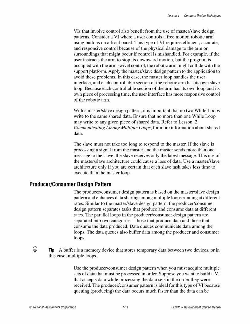
VIs that involve control also benefit from the use of master/slave design patterns. Consider a VI where a user controls a free motion robotic arm using buttons on a front panel. This type of VI requires efficient, accurate, and responsive control because of the physical damage to the arm or surroundings that might occur if control is mishandled. For example, if the user instructs the arm to stop its downward motion, but the program is occupied with the arm swivel control, the robotic arm might collide with the support platform. Apply the master/slave design pattern to the application to avoid these problems. In this case, the master loop handles the user interface, and each controllable section of the robotic arm has its own slave loop. Because each controllable section of the arm has its own loop and its own piece of processing time, the user interface has more responsive control of the robotic arm.
With a master/slave design pattern, it is important that no two While Loops write to the same shared data. Ensure that no more than one While Loop may write to any given piece of shared data. Refer to Lesson 2, Communicating Among Multiple Loops, for more information about shared data.
The slave must not take too long to respond to the master. If the slave is processing a signal from the master and the master sends more than one message to the slave, the slave receives only the latest message. This use of the master/slave architecture could cause a loss of data. Use a master/slave architecture only if you are certain that each slave task takes less time to execute than the master loop.
Producer/Consumer Design PatternThe producer/consumer design pattern is based on the master/slave design pattern and enhances data sharing among multiple loops running at different rates. Similar to the master/slave design pattern, the producer/consumer design pattern separates tasks that produce and consume data at different rates. The parallel loops in the producer/consumer design pattern are separated into two categories—those that produce data and those that consume the data produced. Data queues communicate data among the loops. The data queues also buffer data among the producer and consumer loops.
Tip A buffer is a memory device that stores temporary data between two devices, or in this case, multiple loops.
Use the producer/consumer design pattern when you must acquire multiple sets of data that must be processed in order. Suppose you want to build a VI that accepts data while processing the data sets in the order they were received. The producer/consumer pattern is ideal for this type of VI because queuing (producing) the data occurs much faster than the data can be
Lesson 1 Common Design Techniques
LabVIEW Development Course Manual 1-12 ni.com
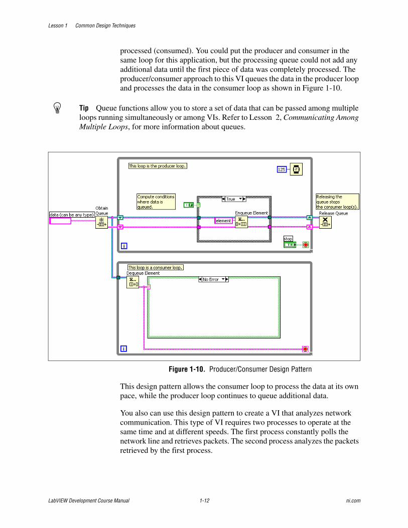
processed (consumed). You could put the producer and consumer in the same loop for this application, but the processing queue could not add any additional data until the first piece of data was completely processed. The producer/consumer approach to this VI queues the data in the producer loop and processes the data in the consumer loop as shown in Figure 1-10.
Tip Queue functions allow you to store a set of data that can be passed among multiple loops running simultaneously or among VIs. Refer to Lesson 2, Communicating Among Multiple Loops, for more information about queues.
Figure 1-10. Producer/Consumer Design Pattern
This design pattern allows the consumer loop to process the data at its own pace, while the producer loop continues to queue additional data.
You also can use this design pattern to create a VI that analyzes network communication. This type of VI requires two processes to operate at the same time and at different speeds. The first process constantly polls the network line and retrieves packets. The second process analyzes the packets retrieved by the first process.

Lesson 1 Common Design Techniques
© National Instruments Corporation 1-13 LabVIEW Development Course Manual
In this example, the first process acts as the producer because it supplies data to the second process, which acts as the consumer. The producer/consumer design pattern is an effective architecture for this VI. The parallel producer and consumer loops handle the retrieval and analysis of data off the network, and the queued communication between the two loops allows buffering of the network packets retrieved. Buffering can become important when network communication is busy. With buffering, packets can be retrieved and communicated faster than they can be analyzed.
D. Timing a Design PatternThis section discusses two forms of timing—execution timing and software control timing. Execution timing uses timing functions to give the processor time to complete other tasks. Software control timing involves timing a real-world operation to perform within a set time period.
Execution TimingYou can time a design pattern explicitly or based on events that occur within the VI. Explict timing provides the design pattern with a function that specifically allows the processor time to complete other tasks, such as the Wait Until Next ms Multiple function. When timing is based on events, the design pattern waits for some action to occur before continuing and allows the processor to complete other tasks while it waits.
Use explicit timing for design patterns such as the master/slave, producer/consumer, and state machine. These design patterns perform some type of polling while they execute.
Tip Polling is the process of making continuous requests for data from another device. In LabVIEW, this generally means that the block diagram continuously asks if there is data available, usually from the user interface.
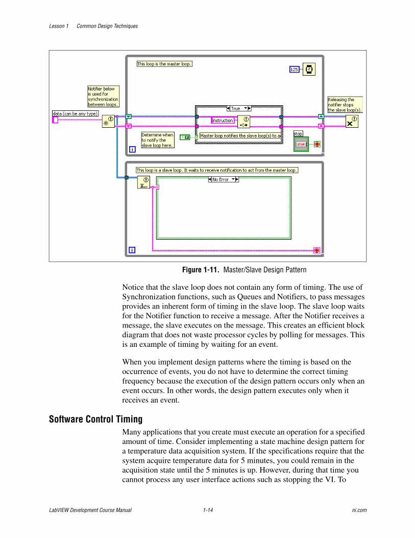
For example, the master/slave design pattern shown in Figure 1-11 uses a While Loop and a Case structure to implement the master loop. The master executes continuously and polls for an event of some type, such as the user pressing a switch. When the event occurs, the master sends a message to the slave. You need to time the master so it does not take over the execution of the processor. In this case, you typically use the Wait (ms) function to regulate how frequently the master polls. Always use a timing function such as the Wait (ms) function or the Wait Until Next ms Multiple function in any design pattern that continually executes and needs to be regulated. If you do not use a timing function in a continuously executing structure, LabVIEW uses all the processor time, and background processes may not run.
Lesson 1 Common Design Techniques
LabVIEW Development Course Manual 1-14 ni.com
Figure 1-11. Master/Slave Design Pattern
Notice that the slave loop does not contain any form of timing. The use of Synchronization functions, such as Queues and Notifiers, to pass messages provides an inherent form of timing in the slave loop. The slave loop waits for the Notifier function to receive a message. After the Notifier receives a message, the slave executes on the message. This creates an efficient block diagram that does not waste processor cycles by polling for messages. This is an example of timing by waiting for an event.
When you implement design patterns where the timing is based on the occurrence of events, you do not have to determine the correct timing frequency because the execution of the design pattern occurs only when an event occurs. In other words, the design pattern executes only when it receives an event.
Software Control TimingMany applications that you create must execute an operation for a specified amount of time. Consider implementing a state machine design pattern for a temperature data acquisition system. If the specifications require that the system acquire temperature data for 5 minutes, you could remain in the acquisition state until the 5 minutes is up. However, during that time you cannot process any user interface actions such as stopping the VI. To

Lesson 1 Common Design Techniques
© National Instruments Corporation 1-15 LabVIEW Development Course Manual
process these user interface action, you must implement timing so that the VI continually executes for the specified time. Implementing this timing involves keeping the application executing while monitoring a real-time clock.
In the LabVIEW Basics I course, you implemented software control timing to monitor the time until the VI should acquire the next piece of data, as shown in Figure 1-12. Notice the use of the Elapsed Time Express VI to keep track of a clock.
Figure 1-12. Use of the Elapsed Time Express VI
If you use the Wait (ms) function or the Wait Until Next ms Multiple function to perform software timing, the wait function must finish before the function you are timing can execute. These functions are not the preferred method for performing software control timing, especially for VIs where the system must continually execute. A good pattern to use for timing is to cycle the current time throughout the VI, as shown in Figure 1-13.

Lesson 1 Common Design Techniques
LabVIEW Development Course Manual 1-16 ni.com
Figure 1-13. Software Timing Using the Get Date/Time In Seconds Function
The Get Date/Time In Seconds function, connected to the left terminal of the shift register, initializes the shift register with the current system time. Each state uses another Get Date/Time In Seconds function and compares the current time to the start time. If the difference in these two times is greater or equal to the wait time, the state finishes executing and the rest of the application executes. Always use the Get Date/Time In Seconds function instead of the Tick Count function for this type of comparison because the value of the Tick Count function can rollover to 0 during execution.
Refer to Lesson 2, Communicating Among Multiple Loops, for more information on creating a timing functional global variable to make the timing functionality modular and reusable.

Lesson 1 Common Design Techniques
© National Instruments Corporation 1-17 LabVIEW Development Course Manual
Self-Review: Quiz
1. Software control timing allows the processor time to complete other tasks.
a. True
b. False
2. Execution timing is a method for allowing the processor time to complete other tasks.
a. True
b. False
3. You can use a wire to pass data between parallel loops.
a. True
b. False

Self-Review: Quiz Answers
1. FALSE: Software control timing is a method for allowing the processor time to complete other tasks.
2. TRUE: Execution timing is a method for allowing the processor time to complete other tasks.
3. FALSE: You can use a wire to pass data between parallel loops.

Lesson 1 Common Design Techniques
© National Instruments Corporation 1-19 LabVIEW Development Course Manual
Notes

Lesson 1 Common Design Techniques
LabVIEW Development Course Manual 1-20 ni.com
Notes

© National Instruments Corporation 2-1 LabVIEW Development Course Manual
2Communicating Among Multiple Loops
In Lesson 1, Common Design Techniques, you learned the difficulties of transferring data among multiple loops without imposing a serial execution order on the loops. This lesson describes messaging techniques for transferring data among multiple loops. These messaging techniques include variables, notifiers, and queues. You also learn about the programming issues involved in using these techniques and methods for overcoming these challenges.
TopicsA. Variables
B. Functional Global Variables
C. Race Conditions
D. Synchronizing Data Transfer

Lesson 2 Communicating Among Multiple Loops
LabVIEW Development Course Manual 2-2 ni.com
A. VariablesIn LabVIEW, the flow of data rather than the sequential order of commands determines the execution order of block diagram elements. Therefore, you can create block diagrams that have simultaneous operations. For example, you can run two For Loops simultaneously and display the results on the front panel, as shown in the following block diagram.
However, if you use wires to pass data between parallel block diagrams, they no longer operate in parallel. Parallel block diagrams can be two parallel loops on the same block diagram without any data flow dependency or two separate VIs that are called at the same time.
The block diagram in Figure 2-1 does not run the two loops in parallel because of the wire between the two subVIs.
Figure 2-1. While Loops with a Data Dependency Imposed by Wire
The wire creates a data dependency, because the second loop does not start until the first loop finishes and passes the data through its tunnel. To make the two loops run concurrently, remove the wire. To pass data between the subVIs, use another technique, such as a variable.

Lesson 2 Communicating Among Multiple Loops
© National Instruments Corporation 2-3 LabVIEW Development Course Manual
In LabVIEW, variables are block diagram elements that allow you to access or store data in another location. The actual location of the data varies depending upon the type of the variable. Local variables store data in front panel controls and indicators. Global variables and single process shared variables store data in special repositories that you can access from multiple VIs. Functional global variables store data in while loop shift registers. Regardless of where the variable stores data, all variables allow you to circumvent normal dataflow by passing data from one place to another without connecting the two places with a wire. For this reason, variables are useful in parallel architectures, but also have certain drawbacks, such as race conditions.
Using Variables in a Single VILocal variables transfer data within a single VI.
Creating Local VariablesRight-click an existing front panel object or block diagram terminal and select Create»Local Variable from the shortcut menu to create a local variable. A local variable icon for the object appears on the block diagram.
You also can select a local variable from the Functions palette and place it on the block diagram. The local variable node, shown as follows, is not yet associated with a control or indicator.
To associate a local variable with a control or indicator, right-click the local variable node and select Select Item from the shortcut menu. The expanded shortcut menu lists all the front panel objects that have owned labels.
LabVIEW uses owned labels to associate local variables with front panel objects, so label the front panel controls and indicators with descriptive owned labels.
Reading and Writing to VariablesAfter you create a local or global variable, you can read data from a variable or write data to it. By default, a new variable receives data. This kind of variable works as an indicator and is a write local or global. When you write new data to the local or global variable, the associated front panel control or indicator updates to the new data.
You also can configure a variable to behave as a data source, or a read local or global. Right-click the variable and select Change To Read from the shortcut menu to configure the variable to behave as a control. When this

Lesson 2 Communicating Among Multiple Loops
LabVIEW Development Course Manual 2-4 ni.com
node executes, the VI reads the data in the associated front panel control or indicator.
To change the variable to receive data from the block diagram rather than provide data, right-click the variable and select Change To Write from the shortcut menu.
On the block diagram, you can distinguish read locals or globals from write locals or globals the same way you distinguish controls from indicators. A read local or global has a thick border similar to a control. A write local or global has a thin border similar to an indicator.
Local Variable ExampleIn the Parallelism section of Lesson 1 Common Design Techniques, you saw an example of a VI that used parallel loops. The front panel contained a single switch that stopped the data generation displayed on two graphs. On the block diagram, the data for each chart is generated within an individual While Loop to allow for separate timing of each loop. The Loop Control terminal stopped both While Loops. In this example, the two loops must share the switch to stop both loops at the same time.
For both charts to update as expected, the While Loops must operate in parallel. Connecting a wire between While Loops to pass the switch data makes the While Loops execute serially, rather than in parallel. Figure 2-2 shows a block diagram of this VI using a local variable to pass the switch data.
Loop 2 reads a local variable associated with the switch. When you set the switch to False on the front panel, the switch terminal in Loop 1 writes a False value to the conditional terminal in Loop 1. Loop 2 reads the Loop Control local variable and writes a False to the Loop 2 conditional terminal. Thus, the loops run in parallel and terminate simultaneously when you turn off the single front panel switch.
Figure 2-2. Local Variable Used to Stop Parallel Loops
With a local variable, you can write to or read from a control or indicator on the front panel. Writing to a local variable is similar to passing data to any

Lesson 2 Communicating Among Multiple Loops
© National Instruments Corporation 2-5 LabVIEW Development Course Manual
other terminal. However, with a local variable you can write to it even if it is a control or read from it even if it is an indicator. In effect, with a local variable, you can access a front panel object as both an input and an output.
For example, if the user interface requires users to log in, you can clear the Login and Password prompts each time a new user logs in. Use a local variable to read from the Login and Password string controls when a user logs in and to write empty strings to these controls when the user logs out.
Using Variables Among VIsYou also can use variables to access and pass data among several VIs that run simultaneously. A local variable shares data within a VI; a global variable also shares data, but it shares data with multiple VIs. For example, suppose you have two VIs running simultaneously. Each VI contains a While Loop and writes data points to a waveform chart. The first VI contains a Boolean control to terminate both VIs. You can use a global variable to terminate both loops with a single Boolean control. If both loops were on a single block diagram within the same VI, you could use a local variable to terminate the loops.
You also can use a single process shared variable in the same way you use a global variable. A shared variable is similar to a local variable or a global variable, but allows you to share data across a network. A shared variable can be single-process or network published. Although you do not learn to use network published shared variables in this course, by using the single-process shared variable, you can later change to a network published shared variable without much difficulty.
Use a global variable to share data among VIs on the same computer, especially if you do not use a project file. Use a single process shared variable if you may need to share the variable information among VIs on multiple computers in the future.
Creating Global Variables Use global variables to access and pass data among several VIs that run simultaneously. Global variables are built-in LabVIEW objects. When you create a global variable, LabVIEW automatically creates a special global VI, which has a front panel but no block diagram. Add controls and indicators to the front panel of the global VI to define the data types of the global variables it contains. In effect, this front panel is a container from which several VIs can access data.
For example, suppose you have two VIs running simultaneously. Each VI contains a While Loop and writes data points to a waveform chart. The first VI contains a Boolean control to terminate both VIs. You must use a global variable to terminate both loops with a single Boolean control. If both loops
Lesson 2 Communicating Among Multiple Loops
LabVIEW Development Course Manual 2-6 ni.com
were on a single block diagram within the same VI, you could use a local variable to terminate the loops.
Select a global variable, shown as follows, from the Functions palette and place it on the block diagram.
Double-click the global variable node to display the front panel of the global VI. Place controls and indicators on this front panel the same way you do on a standard front panel.
LabVIEW uses owned labels to identify global variables, so label the front panel controls and indicators with descriptive owned labels.
You can create several single global VIs, each with one front panel object, or you can create one global VI with multiple front panel objects. A global VI with multiple objects is more efficient because you can group related variables together. The block diagram of a VI can include several global variable nodes that are associated with controls and indicators on the front panel of a global VI. These global variable nodes are either copies of the first global variable node that you placed on the block diagram of the global VI, or they are the global variable nodes of global VIs that you placed on the current VI. You place global VIs on other VIs the same way you place subVIs on other VIs. Each time you place a new global variable node on a block diagram, LabVIEW creates a new VI associated only with that global variable node and copies of it.
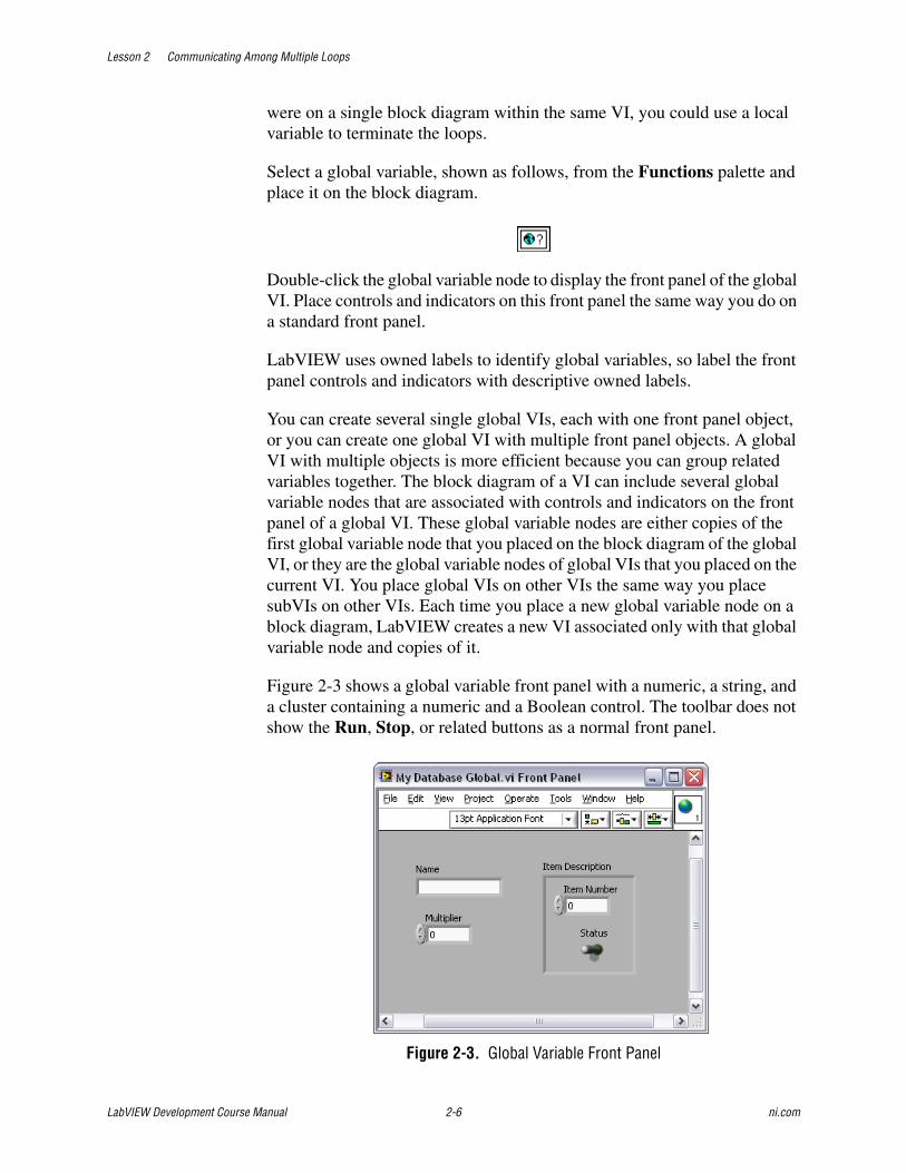
Figure 2-3 shows a global variable front panel with a numeric, a string, and a cluster containing a numeric and a Boolean control. The toolbar does not show the Run, Stop, or related buttons as a normal front panel.
Figure 2-3. Global Variable Front Panel

Lesson 2 Communicating Among Multiple Loops
© National Instruments Corporation 2-7 LabVIEW Development Course Manual
After you finish placing objects on the global VI front panel, save it and return to the block diagram of the original VI. You must then select the object in the global VI that you want to access. Right-click the global variable node and select a front panel object from the Select Item shortcut menu. The shortcut menu lists all the front panel objects in the global VI that have owned labels.
You also can use the Operating tool or Labeling tool to click the global variable node and select the front panel object from the menu that displays.
If you want to use this global variable in other VIs, select Functions»All Functions»Select a VI. By default, the global variable is associated with the first front panel object with an owned label that you placed in the global VI. Right-click the global variable node you placed on the block diagram and select a front panel object from the Select Item shortcut menu to associate the global variable with the data from another front panel object.
Creating Single Process Shared VariablesYou must use a project file to use a shared variable. To create a single process shared variable, right-click My Computer in the Project Explorer window and select New»Variable. The Shared Variable dialog box appears, as shown in Figure 2-4.
Figure 2-4. Shared Variable Properties Dialog Box
Under Variable Type, select Single Process. Give the variable a name and a data type. After you create the global variable, it automatically appears in

Lesson 2 Communicating Among Multiple Loops
LabVIEW Development Course Manual 2-8 ni.com
a new library in your project file. Save the library. You can additional global variables to this library as needed. You can drag and drop the variable from the listing in the Project Explorer window, directly to the block diagram. Use the short-cut menu to switch between writing or reading. Use the error clusters on the variable to impose dataflow.
Using Variables CarefullyLocal and global variables are advanced LabVIEW concepts. They are inherently not part of the LabVIEW dataflow execution model. Block diagrams can become difficult to read when you use local and global variables, so you should use them carefully. Misusing local and global variables, such as using them instead of a connector pane or using them to access values in each frame of a sequence structure, can lead to unexpected behavior in VIs. Overusing local and global variables, such as using them to avoid long wires across the block diagram or using them instead of data flow, slows performance.
Variables often are used unnecessarily. The example in Figure 2-5 shows a traffic light application implemented as a state machine. Each state updates the lights for the next stage of the light sequence. In the state shown, the east and west traffic has a green light, while the north and south traffic has a red light. This stage waits for 4 seconds, as shown by the Wait (ms) function.

Lesson 2 Communicating Among Multiple Loops
© National Instruments Corporation 2-9 LabVIEW Development Course Manual
Figure 2-5. Too Many Variables Used
The example shown in Figure 2-6 accomplishes exactly the same task, but more efficiently and using a better design. Notice that this example is much easier to read and understand than the previous example, mostly by reducing variable use. By placing the indicators in the While Loop outside of the Case structure, the indicators can update after every state without using a variable. This example is less difficult to modify for further functionality, such as adding left turn signals, than the previous example.

Lesson 2 Communicating Among Multiple Loops
LabVIEW Development Course Manual 2-10 ni.com
Figure 2-6. Variable Use Reduction
Initializing Variables
Verify that the local and global variables contain known data values before the VI runs. Otherwise, the variables might contain data that cause the VI to behave incorrectly.
If you do not initialize the variable before the VI reads the variable for the first time, the variable contains the default value of the associated front panel object.
Figure 2-7 shows a common mistake when using variables. A shared variable synchronizes the stop conditions for two loops. This example operates the first time it runs, because the default value of a Boolean is False. However, each time this VI runs the Stop control writes a True value into the variable. Therefore, the second and subsequent times that this VI runs, the lower loop stops after only a single iteration unless the first loop updates the variable quickly enough.

Lesson 2 Communicating Among Multiple Loops
© National Instruments Corporation 2-11 LabVIEW Development Course Manual
Figure 2-7. Failing to Initialize a Shared Variable
Figure 2-8 shows the proper implementation of the program. Initialize the variable before the loops begin to insure that the second loop does not immediately stop.
Figure 2-8. Initializing a Shared Variable Properly
B. Functional Global VariablesYou can use uninitialized shift registers in For Loops or While Loops to hold data as long as the VI never goes out of memory. The shift register holds the last state of the shift register. Place a While Loop within a subVI and use the shift registers to store data that can be read from or written to. Using this technique is similar to using a global variable. This method is often called a functional global variable. The advantage to this method over a global variable is that you can control access to the data in the shift register. The general form of a functional global variable includes an uninitialized shift register with a single iteration For or While Loop, as shown in Figure 2-9.

Lesson 2 Communicating Among Multiple Loops
LabVIEW Development Course Manual 2-12 ni.com
Figure 2-9. Functional Global Variable Format
A functional global variable usually has an action input parameter that specifies which task the VI performs. The VI uses an uninitialized shift register in a While Loop to hold the result of the operation.
Figure 2-10 shows a simple functional global variable with set and get functionality.
Figure 2-10. Functional Global Variable with Set and Get Functionality
In this example, data passes into the VI and the shift register stores the data if you configure the enumerated data type to Set. Data is retrieved from the shift register if the enumerated data type is configured to Get.
Although you can use functional global variables to implement simple global variables, as shown in the previous example, they are especially
1 Uninitialized Shift Register
1

Lesson 2 Communicating Among Multiple Loops
© National Instruments Corporation 2-13 LabVIEW Development Course Manual
useful when implementing more complex data structures, such as a stack or a queue buffer. You also can use functional global variables to protect access to global resources, such as files, instruments, and data acquisition devices, that you cannot represent with a global variable.
Note A functional global variable is a subVI that is not reentrant. This means that when the subVI is called from multiple locations, the same copy of the subVI is used. Therefore, only one call to the subVI can occur at a time.
Using Functional Global Variables for TimingOne powerful application of functional global variables is to perform timing in your VI. Many VIs that perform measurement and automation require some form of timing. Often an instrument or hardware device needs time to initialize, and you must build explicit timing into your VI to take into account the physical time required to initialize a system. You can create a functional global variable that measures the elapsed time between each time the VI is called, as shown in Figure 2-11.
Figure 2-11. Elapsed Time Functional Global Variable
The Elapsed Time case gets the current date and time in seconds and subtracts it from the time that is stored in the shift register. The Reset Time case initializes the functional global variable with a known time value.
The Elapsed Time Express VI implements the same functionality as this functional global variable. The benefit of using the functional global variable is that you can customize the implementation easily, such as adding a pause option.

Lesson 2 Communicating Among Multiple Loops
LabVIEW Development Course Manual 2-14 ni.com
Exercise 2-1 Variables VI
GoalUse variables to write to and read from a control
ScenarioYou have a LabVIEW Project that implements a temperature weather station. The project acquires a temperature every half a second, analyzes each temperature to determine if the temperature is too high or too low, then alerts the user if there is a danger of a heat stroke or freeze. The program logs the data if a warning occurs.
Two front panel controls determine the setpoints: the temperature upper limit and the temperature lower limit. However, nothing prevents the user from setting a lower limit that is higher than the upper limit.
Your goal is to use variables to set the lower limit equal to the upper limit if the user sets a lower limit that is higher than the upper limit.

Lesson 2 Communicating Among Multiple Loops
© National Instruments Corporation 2-15 LabVIEW Development Course Manual
DesignThe VIs in this project have already been written. Your only task is to modify the VIs so that the lower limit is set equal to the upper limit when necessary.
State DefinitionsThe following table describes the states in the state machine.
Changing the value of the lower temperature limit control should happen after the user has entered the value but before the value determines the warning level. Therefore, make the modifications to the VI in the Acquisition or Analysis state, or place a new state between the two.
Before determining which option to use, take a closer look at the content of the Acquisition and Analysis states:
❑ Open the Weather Station project located in the C:\Exercises\LabVIEW Basics II\Variables directory.
❑ Open Weather Station UI.vi.
❑ Review the contents of the Acquisition and Analysis states, which correspond to the Acquisition and Analysis cases of the Case structure.
State Description Next State
Acquisition Set time to zero, acquire data from the temperature sensor, and read front panel controls
Analysis
Analysis Determine warning level Data Log if a warning occurs; Time Check if no warning occurs
Data Log Log the data in a tab-delimited ASCII file
Time Check
Time Check Check whether time is greater than or equal to .5 seconds
Acquisition if time has elapsed; Time Check if time has not elapsed

Lesson 2 Communicating Among Multiple Loops
LabVIEW Development Course Manual 2-16 ni.com
Design OptionsYou have three different design options for modifying this project.
Option Description Benefits/Drawbacks
1 Insert a Case structure in the Acquisition state to reset the controls before a local variable writes the values to the cluster.
Poor design: the acquisition state has another task added, rather than focusing only on acquisition.
2 Insert a new state in the state machine that checks the controls and resets them if necessary.
Ability to control when the state occurs.
3 Modify the Determine Warnings subVI to reset the controls.
Easy to implement because functionality is already partially in place. However, if current functionality is used, one set of data always is lost when resetting the lower limit control.

Lesson 2 Communicating Among Multiple Loops
© National Instruments Corporation 2-17 LabVIEW Development Course Manual
This exercise implements Option 2 as a solution.
New State Definitions for Option 2The following table describes the new state definitions you implement in the implementation section.
State Description Next State
Acquisition Acquire data from the temperature sensor on channel AI0 and read front panel controls
Range Check
Range Check
Read front panel controls and set the lower limit equal to the upper limit if upper limit less than the lower limit
Analysis
Analysis Determine warning level Data Log if a warning occurs; Time Check if no warning occurs
Data Log Log the data in a tab-delimited ASCII file
Time Check
Time Check Check whether time is greater than or equal to .5 seconds
Acquisition if time has elapsed; Time Check if time has not elapsed

Lesson 2 Communicating Among Multiple Loops
LabVIEW Development Course Manual 2-18 ni.com
Implementation1. If the Weather Station.lvproj is not already open, open it from the
C:\Exercises\LabVIEW Basics II\Variables directory.
Note If you do not have a data acquisition device and a DAQ Signal Accessory available, use the files located in the C:\Exercises\LabVIEW Basics II\No Hardware Required\Variables directory instead.
2. Add the Range Check state to the state machine.
❑ From the Project Explorer window, open the Weather Station States.ctl by double-clicking the listing. This is the type-defined enumerated control that defines the states for the state machine.
❑ Right-click the control and select Edit Items from the shortcut menu.
❑ Insert an item and modify to match Table 2-1. Be careful not to add an empty listing.
❑ Save and close the control.
❑ If the Weather Station UI.vi is not open, open it by double-clicking the listing in the Project Explorer window.
❑ Open the block diagram.
❑ Right-click the state machine Case structure and select Add Case for Every Value from the shortcut menu. Because the enumerated control has a new value, a new case appears in the Case structure.
3. Read the upper and lower limit controls in the Range Check state, instead of the Acquisition state.
Table 2-1. States Enumerated Control
Item Digital Display
Acquisition 0
Range Check 1
Analysis 2
Data Log 3
Time Check 4

Lesson 2 Communicating Among Multiple Loops
© National Instruments Corporation 2-19 LabVIEW Development Course Manual
Figure 2-12. Completed Acquisition State
❑ Select the Acquisition case in the state machine Case structure.
❑ Inside the Acquisition case, change the Next State enumerated constant to Range Check.
❑ Make a copy of the Next State enumerated constant by pressing <Ctrl> and dragging a copy outside of the While loop.
❑ Move the Upper Limit and Lower Limit numeric controls outside of the While loop.
❑ Resize the Bundle by Name function to one element, as shown in Figure 2-12.
❑ Select the Range Check case in the state machine Case structure.
❑ Move the Upper Limit and Lower Limit numeric controls and the Next State enumerated constant into the Range Check state.

Lesson 2 Communicating Among Multiple Loops
LabVIEW Development Course Manual 2-20 ni.com
4. Set the Range Check state to transition to the Analysis state.
❑ In the Range Check case, wire the Next State enumerated constant to the Next State output tunnel.
❑ Change the Next State enumerated constant to Analysis.
5. If the Upper Limit is less than the Lower Limit, use a local variable to write the Upper Limit value to the Lower Limit control.
Figure 2-13. Completed Range Check State—True
❑ Place a Less? function in the Range Check state.
❑ Place a Case structure to the right of the Less? function.
❑ Wire the Upper Limit and Lower Limit terminals to the Less? function and the Case structure as shown in Figure 2-13.
❑ Right-click the Lower Limit terminal and select Create»Local Variable from the shortcut menu.
❑ Move the local variable inside the True case of the Case structure.
❑ Place a Bundle By Name function to the right of the Case structure.
❑ Wire the Temperature Data cluster to the input cluster terminal of the Bundle By Name function.

Lesson 2 Communicating Among Multiple Loops
© National Instruments Corporation 2-21 LabVIEW Development Course Manual
❑ Expand the Bundle By Name function to two elements.
❑ Select T Upper Limit in the first element and T Lower Limit in the second element.
❑ Place a False constant in the Case structure.
❑ Wire the case as shown in Figure 2-13.
6. If the Upper Limit is equal to or greater than the Lower Limit, pass the values of the controls to the temperature cluster.
Figure 2-14. Completed Range Check State—False
❑ Switch to the False case of the interior Case structure.
❑ Wire the input Upper Limit tunnel to the output Upper Limit tunnel.
❑ Wire the input Lower Limit tunnel to the output Lower Limit tunnel.
7. Save the VI.
8. Save the Project.

Lesson 2 Communicating Among Multiple Loops
LabVIEW Development Course Manual 2-22 ni.com
Testing1. Run the VI.
❑ Name the log file when prompted.
❑ Enter a value in the Upper Limit control that is less than the value in the Lower Limit control. Does the VI behave as expected?
2. Stop the VI when you are finished.
3. Close the VI and the project.
End of Exercise 2-1

Lesson 2 Communicating Among Multiple Loops
© National Instruments Corporation 2-23 LabVIEW Development Course Manual
C. Race ConditionsA race condition is a situation where the timing of events or the scheduling of tasks may unintentionally affect an output or data value. Race conditions are a common problem for programs that execute multiple tasks in parallel and share data between them. Consider the following example in Figures 2-15 and 2-16.
Figure 2-15. Race Condition Example: Loop 1
Figure 2-16. Race Condition Example: Loop 2
The two loops both increment a shared variable during each iteration. If you run this program, the expected result after pressing the Stop button is that the Total Count is equal to the sum of Count 1 and Count 2. If you run the program for a short period of time, you generally see the expected result. However, if you run the program for a longer period of time, the Total Count is less than the sum of Count 1 and Count 2, because this program contains a race condition.
On a single processor computer, actions in a multi-tasking program like this one actually happen sequentially, but LabVIEW and the operating system rapidly switch tasks so that the tasks effectively execute at the same time. The race condition in this example occurs when the switch from one task to the other occurs at a certain time. Notice that both of the loops performs the following operations:

Lesson 2 Communicating Among Multiple Loops
LabVIEW Development Course Manual 2-24 ni.com
• Read the shared variable.
• Increment the value read.
• Write the incremented value to the shared variable.
Now consider what happens if the loop operations happen to be scheduled in the following order:
1. Loop 1 reads the shared variable.
2. Loop 2 reads the shared variable.
3. Loop 1 increments the value it read.
4. Loop 2 increments the value it read.
5. Loop 1 writes the incremented value to the shared variable.
6. Loop 2 writes the incremented value to the shared variable.
In this example, both loops write the same value to the variable, and the increment of the first loop is effectively overwritten by Loop 2. This generates a race condition, which can cause serious problems if you intend the program to calculate an exact count.
In this particular example, there are few instructions between when the shared variable is read and when it is written. Therefore, the VI is less likely to switch between the loops at the wrong time. This explains why this VI runs fine for short periods and only looses a few counts for longer periods.
Race conditions are difficult to identify and debug, because the outcome depends upon the order in which the operating system executes scheduled tasks and the timing of external events. The way tasks interact with each other and the operating system, as well as the arbitrary timing of external events, make this order essentially random. Often, code with a race condition can return the same result thousands of times in testing, but still can return a different result, which can appear when the code is in use.
The best way to avoid race conditions is by using the following techniques:
• Controlling and limiting shared resources.
• Identifying and protecting critical sections within your code.
• Specifying execution order.
Controlling and Limiting Shared ResourcesRace conditions are most common when two tasks have both read and write access to a resource, as is the case in the above example. A resource is any entity that is shared between the processes. When dealing with race conditions the most common shared resources are data storage, such as

Lesson 2 Communicating Among Multiple Loops
© National Instruments Corporation 2-25 LabVIEW Development Course Manual
variables. Other examples of resources include files and references to hardware resources.
Allowing a resource to be altered from multiple locations often introduces the possibility for a race condition. Therefore, an ideal way to avoid race conditions is to minimize shared resources and the number of writers to the remaining shared resources. In general, it is not harmful to have multiple readers or monitors for a shared resource. However, try to use only one writer or controller for a shared resource. Most race conditions only occur when a resource has multiple writers.
In the previous example, you can reduce the dependency upon shared resources by having each loop maintain its count locally. Then, share the final counts after pressing the Stop button. This involves only a single read and a single write to a shared resource and eliminates the possibility of a race condition. If all shared resources have only a single writer or controller, and the program has a well sequenced instruction order, then race conditions do not occur.
Protecting Critical SectionsA critical section of code is code that may behave inconsistently if some shared resource is altered while it is running. When you use multi-tasking programs, one task may interrupt another task as it is running. In nearly all modern operating systems, this happens constantly. Normally, this does not have any effect upon running code, however, when the interrupting task alters a shared resource that the interrupted task assumes is constant then a race condition occurs.
Figures 2-15 and 2-16 have sections of their code highlighted in red. These sections are critical code sections. If one of the loops interrupts the other loop while it is executing the code in its critical section, then a race condition can occur. One way to eliminate race conditions is to identify and protect the critical sections in your code. There are many techniques for protecting critical sections. Two of the most effective are Functional Global Variables and Semaphores.
Functional Global VariablesOne way to protect critical sections is to place them in SubVIs. You only can call a non-reentrant SubVI from one location at a time. Therefore, placing critical code in a SubVI keeps the code from being interrupted by other processes calling the SubVI. Using the functional global architecture to protect critical sections is particularly effective, as shift registers can replace less protected storage methods like globals or single process shared variables. Functional globals also encourage the creation of multi-functional SubVIs that handle all tasks associated with a particular resource.

Lesson 2 Communicating Among Multiple Loops
LabVIEW Development Course Manual 2-26 ni.com
After you identify each section of critical code in your program, group the sections by the resource they access, and create one functional global for each resource. Critical sections performing different operations each can become a command for the functional global, and you can group critical sections that perform the same operation into one command, thereby re-using code.
You can use functional globals to protect the program in Figure 2-15 and Figure 2-16. Simply replace the shared variables with a functional global variable and place the code to increment the counter within the variable as shown in Figures 2-17, 2-18, and 2-19 show a solution to the race condition using a Functional Global Variable.
Figure 2-17. Using Functional Globals to Protect the Critical Section in Loop 1
Figure 2-18. Using Functional Globals to Protect the Critical Section in Loop 2

Lesson 2 Communicating Among Multiple Loops
© National Instruments Corporation 2-27 LabVIEW Development Course Manual
Figure 2-19. Functional Global Used to Eliminate the Race Condition
SemaphoresSemaphores are synchronization mechanisms specifically designed to protect resources and critical sections of code. You can prevent critical sections of code from interrupting each other by enclosing each between Acquire and Release Semaphore VIs. By default, a semaphore only allows one task to acquire it at a time. Therefore, after one of the tasks enters a critical section, the other tasks cannot enter their critical sections until the first task completes. When done properly, this eliminates the possibility of a race condition.
You can use semaphores to protect the critical sections of the program in Figures 2-15 and 2-16. A named semaphore allows you to share the semaphore between VIs. You must open the semaphore in each VI, then acquire it just before the critical section and release it after the critical section. Figures 2-20 and 2-21 show a solution to the race condition using semaphores.

Lesson 2 Communicating Among Multiple Loops
LabVIEW Development Course Manual 2-28 ni.com
Figure 2-20. Protecting the Critical Section with a Semaphore in Loop 1
Figure 2-21. Protecting the Critical Section with a Semaphore in Loop 2
Specifying Execution OrderCode in which dataflow is not properly used to control the execution order can cause some race conditions. When a data dependency is not established, LabVIEW can schedule tasks in any order, which creates the possibility for race conditions if the tasks depend upon each other. Consider the example in Figure 2-22.
Figure 2-22. Simple Race Condition
The code in this example has four possible outcomes, depending upon the order in which operations execute.

Lesson 2 Communicating Among Multiple Loops
© National Instruments Corporation 2-29 LabVIEW Development Course Manual
Outcome 1: Value = (Value*5)+21. Terminal reads Value.
2. Value*5 is stored in Value.
3. Local variable reads Value*5.
4. (Value*5)+2 is stored in Value.
Outcome 2: Value = (Value+2)*51. Local variable reads Value.
2. Value+2 is stored in Value.
3. Terminal reads Value+2.
4. (Value+2)*5 is stored in Value.
Outcome 3: Value = Value*51. Terminal reads Value.
2. Local variable reads Value.
3. Value+2 is stored in Value.
4. Value*5 is stored in Value.
Outcome 4: Value = Value+21. Terminal reads Value.
2. Local variable reads Value.
3. Value*5 is stored in Value.
4. Value+2 is stored in Value.
Although this code is considered a race condition, the code generally behaves less randomly than the first race condition example. This is because LabVIEW usually assign a consistent order to the operations. However, avoid situations such as this because the order and the behavior of the program is not guaranteed. For example, the order could change when running the program under different conditions or when upgrading the program to a newer version of LabVIEW. Fortunately, race conditions of this nature are easily remedied by controlling the dataflow.

Lesson 2 Communicating Among Multiple Loops
LabVIEW Development Course Manual 2-30 ni.com
Exercise 2-2 Concept: Bank VI
GoalEliminate a race condition.
DescriptionYou must identify and fix a problem with the server software in a bank. The bank server handles requests from many sources and must process the requests quickly. In order to increase its efficiency, the server uses two parallel loops: one to handle deposits to the account and another to handle withdrawals. The problem with the server is that some deposit or withdrawal requests are lost, thereby resulting in incorrect balances.
Testing1. Open Bank.VI in the C:\Exercises\LabVIEW Basics II\Bank
directory.
2. Run the VI.
3. Perform a deposit, a withdrawal and a simultaneous transaction to familiarize yourself with the program.
4. Set the Deposit Amount to 20 and the Withdrawal Amount to 10.
5. Open the block diagram of the Bank VI while it is still running.
6. Arrange the block diagram of the Bank VI so that you can see it while operating the user interface.
7. Enable execution highlighting on the block diagram by pressing Executive Highlighting.
8. Click the Simultaneous Transactions button and watch the code as it executes. The balance should increase by 10.Notice that either the deposit or the withdrawal is lost, causing the balance to increase by 20 or decrease by 10.
9. Stop the VI.
You tracked the problem down to a race condition in a section of a code handling deposits and withdrawals for a single account. Although you can see the issue with execution highlighting enabled, during regular operation, the issue would occur sporadically.

Lesson 2 Communicating Among Multiple Loops
© National Instruments Corporation 2-31 LabVIEW Development Course Manual
Remove the race condition by protecting the critical section of code using a semaphore. In the VI, the critical sections of code are those enclosed by a Sequence structure.
Maintenance1. Save the VI as Bank with Semaphores.vi in the C:\Exercises\
LabVIEW Basics II\Bank directory.
2. Use semaphores to protect the critical sections of code, as shown in Figure 2-23.
Figure 2-23. Bank with Semaphore
❑ Place a Create Semaphore VI to the left of the While Loops.
❑ Wire the Create Semaphore VI as shown in Figure 2-23.
❑ Place an Acquire Semaphore VI in the Deposit Handler loop to the left of the Sequence structure.
❑ Place a second Acquire Semaphore VI in the Withdrawal Handler loop to the left of the Sequence structure.
❑ Wire the Acquire Semaphore VIs as shown in Figure 2-23.
❑ Place a Release Semaphore VI in the Deposit Handler loop to the right of the Sequence structure.

Lesson 2 Communicating Among Multiple Loops
LabVIEW Development Course Manual 2-32 ni.com
❑ Place a second Release Semaphore VI in the Withdrawal Handler loop to the right of the Sequence structure.
❑ Wire the Release Semaphore VIs as shown in Figure 2-23.
❑ Place a Destroy Semaphore VI to the right of the While Loops.
❑ Wire the Destroy Semaphore VI as shown in Figure 2-23. Notice that the Destroy Semaphore VI requires only the reference to the semaphore.
3. Save the VI.
4. Repeat the steps detailed in the Testing section to test the modification to this VI.
5. Close the VI when you are finished.
End of Exercise 2-2

Lesson 2 Communicating Among Multiple Loops
© National Instruments Corporation 2-33 LabVIEW Development Course Manual
D. Synchronizing Data TransferVariables are very useful in LabVIEW for passing data between parallel processes. Notifiers and queues are methods for passing data between parallel processes that has advantages over using variables because of the ability to synchronize the transfer of data.
VariablesFor parallel loops to communicate, you must use some form of globally available shared data. Using a global variable breaks the LabVIEW dataflow paradigm, allows for race conditions, and incurs more overhead than passing the data by wire.
The example shown in Figure 2-24 is a less effective implementation of a master/slave design pattern. This example uses a variable, which causes two problems—there is no timing between the master and the slave, and the variable can cause race conditions. The master cannot signal the slave that data is available, so the slave loop must continually poll the variable to determine if the data changes.
Figure 2-24. Master/Slave Architecture Using Global Variables
NotifiersA more effective implementation of the master/slave design pattern uses notifiers to synchronize data transfer. A notifier sends data along with a notification that the data is available. Using a notifier to pass data from the master to the slave removes any issues with race conditions. Using notifiers also provides a synchronization advantage because the master and slave are timed when data is available, providing for an elegant implementation of the

Lesson 2 Communicating Among Multiple Loops
LabVIEW Development Course Manual 2-34 ni.com
master/slave design pattern. Figure 2-25 shows the master/slave design pattern using notifiers.
Figure 2-25. Master/Slave Design Pattern Using Notifiers
The notifier is created before the loops begin using the Obtain Notifier function. The master loop uses the Send Notification function to notify the slave loop through the Wait on Notification function. After the VI has finished using the notifiers, use the Release Notifier function.
The following benefits result from using notifiers in the master/slave design pattern:
• Both loops are synchronized to the master loop. The slave loop only executes when the master loop sends a notification.
• You can use notifiers to create globally available data. Thus, you can send data with a notification. For example, in Figure 2-25, the Send Notification function sends the string instruction.
• Using notifiers creates efficient code. You must not use polling to determine when data is available from the master loop.
However, using notifiers can have drawbacks. A notifier does not buffer the data. If the master loop sends another piece of data before the slave loop(s) reads the first piece of data , that data is overwritten and lost.

Lesson 2 Communicating Among Multiple Loops
© National Instruments Corporation 2-35 LabVIEW Development Course Manual
QueuesQueues are similar to notifiers, except that a queue can store multiple pieces of data. By default, queues work in a FIFO (first in, first out) manner. Therefore, the first piece of data inserted into the queue is the first piece of data that is removed from the queue. Use a queue when you want all data placed in the queue to be processed. Use a notifier if you only want to process the current data.
When using the producer/consumer design pattern, queues pass data and synchronize the loops.
Figure 2-26. Producer/Consumer Design Pattern Using Queues
The queue is created before the loops begin using the Obtain Queue function. The producer loop uses the Enqueue Element function to add data to the queue. The consumer loop removes data from the queue using the Dequeue Element function. The consumer loop does not execute until data is available in the queue. After the VI has finished using the queues, use the Release Queue function. When the queue releases, the Dequeue Element function generates an error, effectively stopping the consumer loop. Therefore, you do not need a variable to share the Stop between the two loops.

Lesson 2 Communicating Among Multiple Loops
LabVIEW Development Course Manual 2-36 ni.com
The following benefits result from using notifiers in the master/slave design pattern:
• Both loops are synchronized to the producer loop. The consumer loop only executes when data is available in the queue.
• You can use queues to create globally available data that is queued, removing the possibility of losing the data in the queue when new data is added to the queue.
• Using queues creates efficient code. You must not use polling to determine when data is available from the producer loop.
Queues are also useful for holding state requests in a state machine. In the implementation of a state machine that you have learned, if two states are requested simultaneously, you might lose one of the state requests. A queue holds the second state request and execute it when the first has finished.

Lesson 2 Communicating Among Multiple Loops
© National Instruments Corporation 2-37 LabVIEW Development Course Manual
Exercise 2-3 Project: Queue Data
GoalCreate a VI that uses the producer/consumer design pattern and queues to pass data between the loops.
ScenarioYou are given a LabVIEW project that implements a Temperature Weather Station. Throughout this course, you modify this project to measure Wind Speed and determine if a High Wind Warning occurs. Create a producer loop that acquires the temperature and wind speed data at 50 kHz. Transfer the data to the consumer loop using queues. The consumer loop contains the state machine from the original temperature weather station.
DesignFigure 2-27 shows an example of a producer/consumer design pattern without functional elements. In this exercise, place the state machine from the temperature weather station within the No Error case of the consumer loop. Place the code for acquisition of the temperature and wind speed within the producer loop.
Figure 2-27. Example of the Producer/Consumer Design Pattern

Lesson 2 Communicating Among Multiple Loops
LabVIEW Development Course Manual 2-38 ni.com
Refer to Figure 2-28 for the Weather Station flowchart. In this exercise, you complete the following blocks: Initialize Resources, Send 1/2 Second of Temp & Weather Data, and Receive 1/2 Second of Temp & Weather Data.
Figure 2-28. Weather Station Flowchart

Lesson 2 Communicating Among Multiple Loops
© National Instruments Corporation 2-39 LabVIEW Development Course Manual
Implementation1. Open Weather Station.proj in the C:\Exercises\LabVIEW
Basics II\Course Project directory.
Note If you do not have a data acquisition device and a DAQ Signal Accessory, alternate instructions are given where necessary.
2. Open Weather Station UI.vi from the Project Explorer window.
Create Initialization SubVI3. Switch to the block diagram.
Figure 2-29. Create the Initialization SubVI and Consumer Loop
4. Select everything to the left of the state machine, except the Beginning State enumerated constant, and select Edit»Create SubVI.
5. Save the subVI as Initialize Weather Station.vi in the C:\Exercises\LabVIEW Basics II\Course Project\Supporting Files directory. You modify this VI later.
6. Return to the block diagram of the Weather Station UI VI.
Apply Producer/Consumer Design Pattern7. Remove the elapsed time programming for the state machine.
❑ Delete the shift register and Boolean constant connected to the Elapsed Time Express VI.
❑ Remove the Boolean constant in the Time Check state and the Acquisition state that are no longer wired to anything.

Lesson 2 Communicating Among Multiple Loops
LabVIEW Development Course Manual 2-40 ni.com
❑ Delete the Boolean output tunnel from the Case structure.
❑ Delete the Elapsed Time Express VI.
❑ Press <Ctrl-B> to delete all broken wires.
8. Change the label of the cluster control to Weather Data.
9. Reduce the size of the state machine as much as possible. An example appears in Figure 2-30. This step allows you to see as much of the block diagram as possible without scrolling the screen. However, it is not important to functionality, therefore, skip this step if short on time.
10. Place a Case structure around the While Loop, leaving the new subVI and the Beginning State enumerated constant outside of the Case structure.
11. Place a While Loop from the Structures category around the Case structure and the Beginning State enumerated constant, leaving the new subVI outside the While Loop, as shown in Figure 2-29.
The outer While Loop is the consumer loop of the producer/consumer design pattern. In the next steps, you create the producer loop.
12. Scroll the block diagram so that there is empty space above the consumer loop.
13. Place a While Loop from the Structures category above the consumer loop. This is the producer loop.
14. Acquire temperature and wind data at 50 kHz for 5000 samples in the producer loop. If you have a data acquisition board and a DAQ Signal Accessory, follow the instructions in the Hardware section of this step; otherwise follow the instructions in the No Hardware section.
Hardware
❑ Place a DAQ Assistant in the producer loop.
❑ Select Analog Input»Voltage.
❑ Select ai0 and ai1 by holding the <Shift> while you are selecting.
❑ Click the Finish button.
❑ While Voltage0 is selected, select the Temperature scale under the Custom Scaling pull-down menu.

Lesson 2 Communicating Among Multiple Loops
© National Instruments Corporation 2-41 LabVIEW Development Course Manual
If there is no Temperature scale available complete the following steps:
– Under the Custom Scaling pull-down menu, select Create New, then select Linear.
– Name the scale Temperature.
– Click the Finish button.
– In Scaling Parameters, enter a Slope of 100.
– In Units, leave the Pre-Scaled Units as Volts and enter Celsius in Scaled Units.
– Click the OK button.
❑ Set a minimum of 0 and a maximum of 50 for the Celsius Signal Input Range.
❑ On the Task Timing tab, enter 5000 in the Samples to Read input, and 50K in the Rate (Hz) input.
❑ Select Voltage1 to set the settings for the wind speed channel.
❑ Set the Signal Input Range to a Max of 1 and a Min of -1 Volts.
❑ Click the OK button.
❑ Expand the DAQ Assistant to show the error in and error out terminals.
❑ Skip to step 15.
No Hardware
❑ From the Project Explorer window, add Weather Simulator.vi from the C:\Exercises\LabVIEW Basics II\Course Project\Supporting Files directory to the project.
❑ Place a copy of the Weather Simulator VI in the producer loop. This VI simulates the action of acquiring the temperature and wind data.

Lesson 2 Communicating Among Multiple Loops
LabVIEW Development Course Manual 2-42 ni.com
Figu
re 2
-30.
Cre
ate
the
Prod
ucer
Loo
p an
d Qu
eue
the
Data

15. Queue the data produced in the producer loop to send to the consumer loop.
16. Place an Obtain Queue function to the left of the producer loop.
❑ [Hardware] Right-click the data output terminal of the DAQ Assistant and select Create»Graph Indicator from the shortcut menu. [No Hardware] Right-click the data output terminal of the Weather Simulator VI and select Create»Graph Indicator from the shortcut menu.
❑ Right-click the Waveform Graph terminal and select Change to Control from the shortcut menu.
❑ Rename the control Weather Data.
❑ Move the Weather Data terminal to the left of the Obtain Queue function.
❑ Right-click the Weather Data terminal and select Hide Control from the shortcut menu to hide the control on the front panel.
❑ Wire Weather Data to the element data type input of the Obtain Queue function.
❑ Place an Enqueue Element function inside the producer loop.
❑ Wire the Enqueue Element function to the Obtain Queue function, as shown in Figure 2-30.
❑ Place a Release Queue function to the right of the producer loop.
❑ Wire the Release Queue function to the Enqueue Element function and wire the error clusters with shift registers, as shown in Figure 2-30.
17. Dequeue the data from the producer loop inside the consumer loop.
❑ Place a Dequeue Element function inside the consumer loop above the Beginning State enumerated constant.
❑ Wire the Dequeue Element function in the consumer loop as shown in Figure 2-30.

Lesson 2 Communicating Among Multiple Loops
LabVIEW Development Course Manual 2-44 ni.com
Figu
re 2
-31.
Sto
p th
e Lo
ops

Lesson 2 Communicating Among Multiple Loops
© National Instruments Corporation 2-45 LabVIEW Development Course Manual
18. Use the Stop button or an error to stop the producer loop.
❑ Place an Or function in the producer loop.
❑ Move the Stop control from the Time Check state of the state machine to the producer loop.
❑ Place an Unbundle by Name function in the producer loop.
❑ Wire the stop condition of the producer loop as shown in Figure 2-31.
19. Use an error to stop the consumer loop. When the Queue is released, any queue functions still in use produce an error.
❑ Move the loop conditional terminal for the outer While Loop next to the Dequeue Element function.
❑ Confirm that the Loop Condition is set to Stop if True.
❑ Wire the Error Out terminal from the Dequeue Element function to the Loop Condition terminal.
❑ Wire the error out terminal of the Dequeue Element function to the case selector terminal of the outer Case structure, as shown in Figure 2-31. The Case structure has an Error and a No Error case once the error cluster is wired to the case selector.
❑ Switch to the No Error case.
❑ Verify that the state machine code is in the No Error case. If it is not, right-click the Case structure, and select Make This Case No Error from the shortcut menu.
❑ Switch to the Error case. It should be empty.
❑ Wire the file refnum and error cluster through the Error case.
20. Merge the error clusters and report any error at the end of execution.
❑ Disconnect the wire connecting the Close File function and the Simple Error Handler VI.
❑ Place a Merge Errors VI to the right of the Close File function.
❑ Wire the Merge Errors VI and the Simple Error Handler as shown in Figure 2-31.

Lesson 2 Communicating Among Multiple Loops
LabVIEW Development Course Manual 2-46 ni.com
Figure 2-32. Front Panel of the Initialize Weather Station VI
Figure 2-33. Block Diagram of the Initialize Weather Station VI
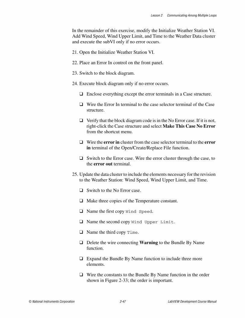
Lesson 2 Communicating Among Multiple Loops
© National Instruments Corporation 2-47 LabVIEW Development Course Manual
In the remainder of this exercise, modify the Initialize Weather Station VI. Add Wind Speed, Wind Upper Limit, and Time to the Weather Data cluster and execute the subVI only if no error occurs.
21. Open the Initialize Weather Station VI.
22. Place an Error In control on the front panel.
23. Switch to the block diagram.
24. Execute block diagram only if no error occurs.
❑ Enclose everything except the error terminals in a Case structure.
❑ Wire the Error In terminal to the case selector terminal of the Case structure.
❑ Verify that the block diagram code is in the No Error case. If it is not, right-click the Case structure and select Make This Case No Error from the shortcut menu.
❑ Wire the error in cluster from the case selector terminal to the error in terminal of the Open/Create/Replace File function.
❑ Switch to the Error case. Wire the error cluster through the case, to the error out terminal.
25. Update the data cluster to include the elements necessary for the revision to the Weather Station: Wind Speed, Wind Upper Limit, and Time.
❑ Switch to the No Error case.
❑ Make three copies of the Temperature constant.
❑ Name the first copy Wind Speed.
❑ Name the second copy Wind Upper Limit.
❑ Name the third copy Time.
❑ Delete the wire connecting Warning to the Bundle By Name function.
❑ Expand the Bundle By Name function to include three more elements.
❑ Wire the constants to the Bundle By Name function in the order shown in Figure 2-33; the order is important.
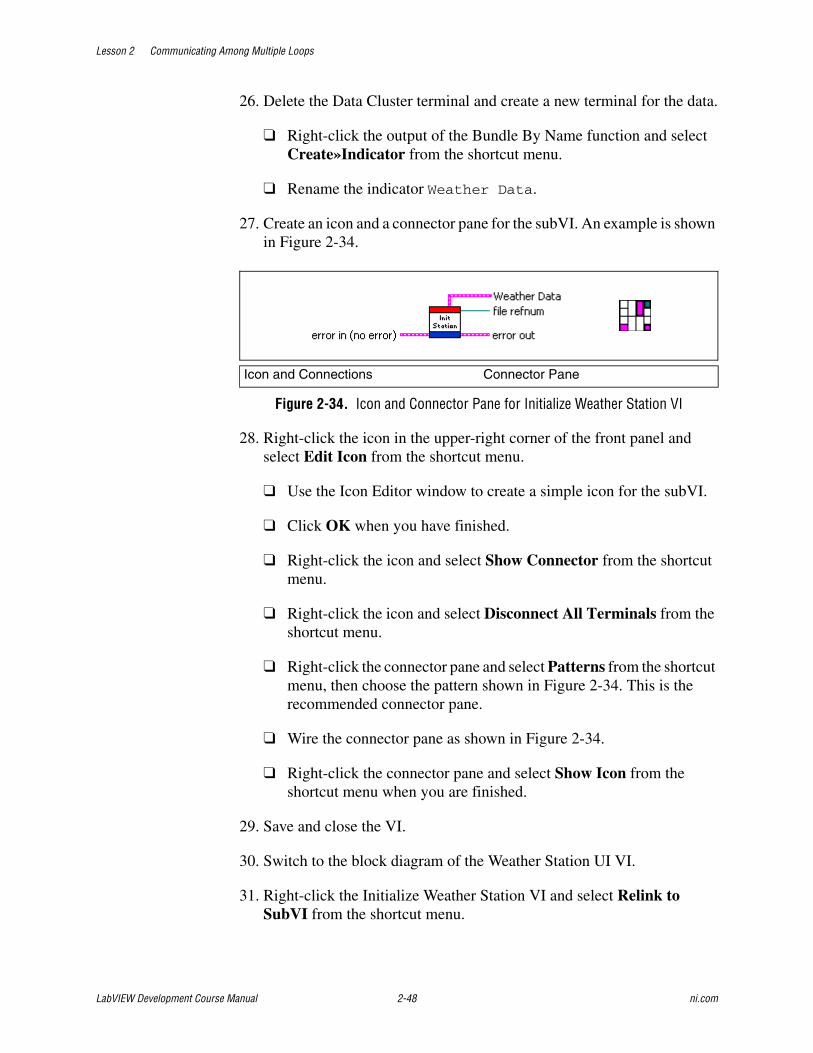
Lesson 2 Communicating Among Multiple Loops
LabVIEW Development Course Manual 2-48 ni.com
26. Delete the Data Cluster terminal and create a new terminal for the data.
❑ Right-click the output of the Bundle By Name function and select Create»Indicator from the shortcut menu.
❑ Rename the indicator Weather Data.
27. Create an icon and a connector pane for the subVI. An example is shown in Figure 2-34.
Figure 2-34. Icon and Connector Pane for Initialize Weather Station VI
28. Right-click the icon in the upper-right corner of the front panel and select Edit Icon from the shortcut menu.
❑ Use the Icon Editor window to create a simple icon for the subVI.
❑ Click OK when you have finished.
❑ Right-click the icon and select Show Connector from the shortcut menu.
❑ Right-click the icon and select Disconnect All Terminals from the shortcut menu.
❑ Right-click the connector pane and select Patterns from the shortcut menu, then choose the pattern shown in Figure 2-34. This is the recommended connector pane.
❑ Wire the connector pane as shown in Figure 2-34.
❑ Right-click the connector pane and select Show Icon from the shortcut menu when you are finished.
29. Save and close the VI.
30. Switch to the block diagram of the Weather Station UI VI.
31. Right-click the Initialize Weather Station VI and select Relink to SubVI from the shortcut menu.
Icon and Connections Connector Pane


Lesson 2 Communicating Among Multiple Loops
LabVIEW Development Course Manual 2-50 ni.com
Figu
re 2
-35.
Sha
re E
rror
s Be
twee
n Pr
oduc
er a
nd C
onsu
mer
Loo
p

Lesson 2 Communicating Among Multiple Loops
© National Instruments Corporation 2-51 LabVIEW Development Course Manual
32. Wire the error out terminal from the Obtain Queue function to the error in terminal of the Initialize Weather Station VI.
33. Your final block diagram should look similar to the one shown in Figure 2-35. Verify that you have completed all the steps.
Your Run button is still broken at this point, because the project is incomplete. You complete the rest of this project in later exercises.
End of Exercise 2-3
Lesson 2 Communicating Among Multiple Loops
LabVIEW Development Course Manual 2-52 ni.com
Exercise 2-4 Optional: Global Data Project
GoalCreate a project containing multiple VIs that share data using a single process shared variable.
ScenarioCreate a VI that generates a sine wave. Create a second VI that displays the sine wave, and allows the user to modify the time between each acquisition of the sine wave data. Use one stop button to stop both VIs.
DesignTwo VIs and two pieces of global data are necessary for the following scenario:
• First shared variable: Stop (Boolean data type)
• Second shared variable: Data (Numeric data type)
• First VI: generate sine, write sine to Data shared variable, read Stop shared variable to stop loop
• Second VI: read Data shared variable, display on chart, write Stop button to Stop shared variable

Lesson 2 Communicating Among Multiple Loops
© National Instruments Corporation 2-53 LabVIEW Development Course Manual
Implementation1. Open a blank project.
2. Save the project as Global Data.lvproj in the C:\Exercises\LabVIEW Basics II\Global Data directory.
3. Create the Stop shared variable.
❑ Switch to the Project Explorer window.
❑ Right-click My Computer and select New»Variable from the shortcut menu.
❑ Give the new variable the following properties:
– Name: Stop
– Data Type: Boolean
– Variable Type: Single-process
❑ Click OK to close the Shared Variable Properties dialog box. Notice that a new library is created in the Project Explorer window to hold the variable.
4. Save the library.
❑ Right-click the library and select Save from the shortcut menu.
❑ Save the library as Global Data.lvlib in the C:/Exercises/LabVIEW Basics II/Global Data directory.
5. Create the Data shared variable.
❑ Switch to the Project Explorer window.
❑ Right-click Global Data.lvlib and select New»Variable from the shortcut menu.
❑ Give the new variable the following properties:
– Name: Data
– Data Type: Double
– Variable Type: Single-process
❑ Click OK to close the Shared Variable Properties dialog box.

Lesson 2 Communicating Among Multiple Loops
LabVIEW Development Course Manual 2-54 ni.com
Generate Data VI1. Open a blank VI.
2. Save the VI as Generate Data.vi in the C:/Exercises/LabVIEW Basics II/Global Data directory.
3. Place a Numeric Indicator on the front panel.
4. Name the Numeric Indicator Data.
5. Switch to the block diagram of the VI.
6. Build the block diagram shown in Figure 2-36. No implementation instructions are given. Labels are shown to assist you.
Figure 2-36. Generate Data Block Diagram w/o Variables
7. Save the VI.
8. Write the data generated to the Data shared variable.
❑ Select the Data shared variable from the Project Explorer window and drag it inside the While loop of the Generate Data VI block diagram.
❑ Right-click the global variable and select Change to Write from the shortcut menu.
❑ Wire the Sin(x) output of the Sine function to the Data shared variable.
9. Read the Stop shared variable to stop the While Loop.
❑ Switch to the Project Explorer window.
❑ Select the Stop shared variable and drag it inside the While Loop of the Generate Data.vi block diagram.

Lesson 2 Communicating Among Multiple Loops
© National Instruments Corporation 2-55 LabVIEW Development Course Manual
❑ Wire the Stop shared variable to the Loop Condition terminal.
10. Initialize the Stop shared variable.
❑ Switch to the Project Explorer window.
❑ Select the Stop shared variable and drag it to the left of the While loop of the Generate Data.vi block diagram.
❑ Right-click the Stop shared variable and select Change to Write from the shortcut menu.
❑ Right-click the input of the Stop shared variable and select Create»Constant from the shortcut menu to create a False constant.
❑ Use the Operating tool to change the constant to a False if necessary.
11. Use the shared variable error clusters to ensure order of operations. Refer to Figure 2-37 for assistance wiring this block diagram.
Figure 2-37. Generate Data Block Diagram with Shared Variables
12. Save the VI.
13. Close the block diagram, but leave the front panel open.

Lesson 2 Communicating Among Multiple Loops
LabVIEW Development Course Manual 2-56 ni.com
Read Data VI1. Open a blank VI.
2. Save the VI as Read Data.vi in the C:/Exercises/LabVIEW Basics II/Global Data directory.
3. Build the front panel shown in Figure 2-38.
Figure 2-38. Read Data Front Panel
4. Place a Vertical Pointer Slide and rename it Time Delay (ms).
❑ Change the range of the slide by entering 200 in the top value shown.
❑ Right-click the slide and select Representation»U8 from the shortcut menu.
❑ Place a Waveform Chart and rename it Data Chart.
❑ Change the x-scale and y-scale ranges and labels of the chart to the values shown in Figure 2-38.
❑ Place a Stop button and hide the label.
5. Open the block diagram.
6. Build the block diagram shown in Figure 2-39. Labels are shown to assist you.

Lesson 2 Communicating Among Multiple Loops
© National Instruments Corporation 2-57 LabVIEW Development Course Manual
Figure 2-39. Read Data Block Diagram w/o Shared Variables
7. Read the data from the Data shared variable and display it on the waveform chart.
❑ Switch to the Project Explorer window.
❑ Select the Data shared variable and drag it inside the While Loop of the Read Data VI block diagram.
❑ Wire the output of the Data global variable to the Data Chart terminal.
8. Write the value of the Stop Boolean to the Stop shared variable.
❑ Switch to the Project Explorer window.
❑ Select the Stop shared variable and drag it inside the While loop of the Read Data.vi block diagram.
❑ Right-click the Stop shared variable and select Change to Write from the shortcut menu.
❑ Wire the Stop terminal to the Stop shared variable.
9. Use the shared variable error clusters to ensure order of operations. Refer to Figure 2-40 for assistance wiring this block diagram.

Lesson 2 Communicating Among Multiple Loops
LabVIEW Development Course Manual 2-58 ni.com
Figure 2-40. Read Data Block Diagram without Shared Variables
10. Save the VI.
11. Close the block diagram.
12. Save the project.
Testing1. Run the Generate Data VI.
2. Run the Read Data VI.
3. Modify the value of the Time Delay (ms) control.
The Time Delay (ms) control determines how often the shared variable is read. What happens if you set the Time Delay to zero? When accessing global data, you may read the value more than once before it is updated to a new value, or you may miss a new value altogether, depending on the value of the Time Delay.
4. Stop and close the VIs and the project when you are finished.
ChallengeCreate a functional global variable to handle the Stop data and use it in Generate Data VI and Read Data VI to share the stop button between the two VIs.
End of Exercise 2-4

Lesson 2 Communicating Among Multiple Loops
© National Instruments Corporation 2-59 LabVIEW Development Course Manual
Self-Review: Quiz
1. Use variables in your VI where ever possible.
a. True
b. False
2. Which of the following cannot transfer data?
a. Semaphores
b. Functional global variables
c. Notifiers
d. Queues
3. Which of the following must be used within a project?
a. Local variable
b. Global variable
c. Functional global variable
d. Single process shared variable
4. Which of the following cannot be used to pass data between multiple VIs?
a. Local variable
b. Global variable
c. Functional global variable
d. Single process shared variable


Lesson 2 Communicating Among Multiple Loops
© National Instruments Corporation 2-61 LabVIEW Development Course Manual
Self-Review: Quiz Answers
1. Use variables in your VI where ever possible.
a. True
b. False
2. Which of the following cannot transfer data?
a. Semaphores
b. Functional global variables
c. Notifiers
d. Queues
3. Which of the following must be used within a project?
a. Local variable
b. Global variable
c. Functional global variable
d. Single process shared variable
4. Which of the following cannot be used to pass data between multiple VIs?
a. Local variable
b. Global variable
c. Functional global variable
d. Single process shared variable

Lesson 2 Communicating Among Multiple Loops
LabVIEW Development Course Manual 2-62 ni.com
Notes

© National Instruments Corporation 3-1 LabVIEW Development Course Manual
3Improving an Existing VI
A common problem when you inherit VIs from other developers is that they might have added features without attention to design, thus making it progressively more difficult to add features later in the life of the VI. This is known as software decay. One solution to software decay is to refactor the software. Refactoring is the process of redesigning software to make it more readable and maintainable so that the cost of change does not increase over time. Refactoring changes the internal structure of a VI to make it more readable and maintainable, without changing its observable behavior.
In this section, you will learn methods to refactor inherited code and experiment with typical issues that appear in inherited code.
Topics
A. Refactoring Inherited Code
B. Typical Issues

Lesson 3 Improving an Existing VI
LabVIEW Development Course Manual 3-2 ni.com
A. Refactoring Inherited CodeWrite large and/or long-term software applications with readability in mind because the cost of reading and modifying the software is likely to outweigh the cost of executing the software. It costs more for a developer to read and understand poorly designed code than it does to read code that was created to be readable. In general, more resources are allocated to reading and modifying software than to the initial implementation. Therefore VIs that are easy to read and modify are more valuable than those that are not.
Although seemingly counterintuitive, well-designed software facilitates rapid development because well-designed software is less prone to decay. If a system starts to decay, you can spend large amounts of time tracking down regression failures, which is not productive. Changes also can take longer to implement because it is harder to understand the system.
Consider the inherited VI shown in Figure 3-1.
Figure 3-1. Inherited VI

Lesson 3 Improving an Existing VI
© National Instruments Corporation 3-3 LabVIEW Development Course Manual
You can refactor the code as shown in Figure 3-2.
Figure 3-2. Refactored Inherited Code
The refactored code performs the same function as the inherited code, but the refactored code is more readable. The inherited code violates many of the block diagram guidelines you have learned. Through refactoring, you can redesign a VI that is difficult to read and maintain and make it readable and maintainable.
When you make a VI easier to understand and maintain, you make it more valuable because it is easier to add features to or debug the VI. The refactoring process does not change observable behavior. Changing the way a VI interacts with clients (users or other VIs) introduces risks that are not present when you limit changes to those visible only to developers. The benefit of keeping the two kinds of changes separate is that you can better manage risks.
Refactoring versus Performance OptimizationAlthough you can make changes that optimize the performance of a VI, this is not the same as refactoring. Refactoring specifically changes the internal structure of a VI to make it easier to read, understand, and maintain. A performance optimization is not refactoring because the goal of optimization is not to make the VI easier to understand and modify. In fact, performance optimization can make VIs more difficult to read and understand, which might be an acceptable trade-off. Sometimes you must sacrifice readability for improved performance, however, readability usually takes priority over speed of performance.

Lesson 3 Improving an Existing VI
LabVIEW Development Course Manual 3-4 ni.com
When to RefactorThe right time to refactor is when you are adding a feature to a VI or debugging it. Although you might be tempted to rewrite the VI from scratch, you should recognize that there is value in a VI that works, even if the block diagram is not readable. Good candidates for complete rewrites are VIs that do not work or VIs that satisfy only a small portion of your needs. You also can rewrite simple VIs that you understand well. Consider what works well in an existing VI before you decide to refactor. Refactoring is a methodical process for restructuring a VI that works well but is written in a way that hinders its readability, scalability, or maintainability.

Lesson 3 Improving an Existing VI
© National Instruments Corporation 3-5 LabVIEW Development Course Manual
Exercise 3-1 Project: Refactor
GoalRefactor the Temperature Weather Station to add functionality.
ScenarioModify the state machine used in the Temperature Weather Station to also monitor the wind speed and generate a High Wind Warning when appropriate. Include a header describing the data in the file.
Design
User Interface Inputs and Outputs
Type Name Properties
Numeric Control1
1. This portion is already completed.
Upper Limit1 Double Precision1
Numeric Control1 Lower Limit1 Double Precision1
Waveform Chart1 Temperature History1
Waveform Chart Wind Speed History
Vertical Pointer Slide Wind Upper Limit Double PrecisionVisible Digital DisplayRange: 0 to 100
String Indicator1 Warning1
Stop Button1 Stop1

Lesson 3 Improving an Existing VI
LabVIEW Development Course Manual 3-6 ni.com
External Inputs and Outputs• Inputs:
– Current temperature retrieved from a sensor attached to AI0 of the data acquisition board.1 Conversion formula: Voltage × 100 = Celsius1
– Current wind speed retrieved from a wind anemometer attached to AI1 of the data acquisition board.Conversion formula: Frequency ÷ 100 = Kilometers per hour (kph)
• Outputs: tab-delimited ASCII file containing current temperature1, temperature limits1, current wind speed, wind speed upper limit, warning string1, and time stamp for each warning that occurs. Include header in the file.
Before: State Transition DiagramBefore adding wind speed measurements to the project, the states used were: Acquisition, Analysis, Data Log, and Time Check, as shown in Figure 3-3.
Figure 3-3. State Transition Diagram for the Temperature Weather Station
1. This portion is already completed.

Lesson 3 Improving an Existing VI
© National Instruments Corporation 3-7 LabVIEW Development Course Manual
After: FlowchartAfter adding the wind speed measurement to the project, the architecture changes to a producer/consumer design pattern, with a state machine embedded in the consumer loop. The new state machine has the following states: Analysis, Process UI, Set Warning, Data Log, and Stop.
Figure 3-4. Flowchart for Weather Temperature Station
The necessary modifications include the following:
1. Adding a control to input the upper wind speed limit and a chart to display the wind speed on the user interface.
2. Including a file header in the initialization area of the VI.
3. Modifying the state machine housed within the producer loop to match the flowchart shown in Figure 3-4.

Lesson 3 Improving an Existing VI
LabVIEW Development Course Manual 3-8 ni.com
State Machine ModificationsMake the modifications shown in the following table to refactor the Temperature Weather Station project to add wind speed functionality.
Acquisition1—the purpose of the old Acquisition1 state has completely changed and been renamed to the Analysis state, because the data now is acquired in the producer loop instead of the state machine. Now the state reads the raw data and converts it to a single Celsius temperature reading and a single kilometers per hour reading, making Analysis a descriptive name for this state.
Analysis1—the old Analysis1 state has been renamed to the Set Warning state, because you must rename the first state so you can choose a more descriptive name for this state.
Time Check1—the old Time Check1 state has been renamed to the Stop state because the new state machine must not measure elapsed time. The producer loop now handles the data acquisition timing.
New State Old State Modifications Necessary
Analysis Acquisition1
1. This portion is already completed.
Remove DAQ Assistant, determine average frequency and average temperature from queue data, move controls and indicators to the Process UI stateNext State: Process UI
Process UI none Read front panel controls to Weather Data cluster; write current values to chartsNext State: Set Warning
Set Warning Analysis1 Replace current Determine Warnings subVI with the Determine More Warnings subVI configured to determine both temperature and wind speed warningsNext State: Data Log or Stop
Data Log Data Log1 Add Wind Speed, Wind Upper Limit and Time to the tab-delimited fileNext State: Stop
Stop Time Check1 Remove time check functionality and stop the state machineNext State: Stop
1. This portion is already completed.
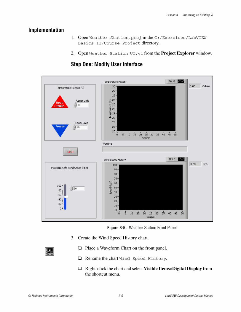
Lesson 3 Improving an Existing VI
© National Instruments Corporation 3-9 LabVIEW Development Course Manual
Implementation1. Open Weather Station.proj in the C:/Exercises/LabVIEW
Basics II/Course Project directory.
2. Open Weather Station UI.vi from the Project Explorer window.
Step One: Modify User Interface
Figure 3-5. Weather Station Front Panel
3. Create the Wind Speed History chart.
❑ Place a Waveform Chart on the front panel.
❑ Rename the chart Wind Speed History.
❑ Right-click the chart and select Visible Items»Digital Display from the shortcut menu.

Lesson 3 Improving an Existing VI
LabVIEW Development Course Manual 3-10 ni.com
❑ Place a label for the units, kph, after the digital display. Create a free label by double-clicking a blank space on the front panel.
Tip After the project is complete, experiment with the x- and y-scales of the charts to set them to an acceptable level.
4. Create the Maximum Safe Wind Speed input.
❑ Place a Vertical Pointer Slide on the front panel.
❑ Right-click the slide and select Properties from the shortcut menu.
❑ In the Appearance tab, change the label to Wind Upper Limit, hide the label and show the digital display.
❑ In the Data Range tab, set the default value to 50.
❑ In the Scale tab, set the Minimum to 0 and the Maximum to 100.
❑ Click OK.
❑ Create a label describing the control, such as Maximum Safe Wind Speed (kph).
❑ If time permits, use decorations to visually enclose the control.
5. Save the VI.
Step Two: Modify File Initialization 6. Open the Initialize Weather Station VI from the Project Explorer
window.
7. Write the file to the same folder as the VI. This is a relative path.
❑ Place a Current VI’s Path function to the left of the Open/Close/Replace function.
❑ Place a Strip Path function to the right of the Current VI’s Path function. This removes the file name of the VI from the path.
❑ Place a Build Path function to the right of the Strip Path function. This removes the file name of the VI from the path.
❑ Right-click the name or relative path input terminal of the Build Path function and select Create»Constant from the shortcut menu.
❑ Enter Weather.txt in the string constant.

Lesson 3 Improving an Existing VI
© National Instruments Corporation 3-11 LabVIEW Development Course Manual
❑ Wire the new path to the Open/Create/Replace File function as shown in Figure 3-6.
8. Write a header to the file to describe the contents of the file.
Figure 3-6. Initialize Weather Station Block Diagram
❑ Place a Write to Text File function to the right of the Open/Close/Replace function.
❑ Delete the output wires from the Open/Close Replace function.
❑ Wire the error cluster and file refnum as shown in Figure 3-6.
❑ Place a Format Into String function above the Write to Text File.
❑ Expand the Format Into String function to have 14 inputs.
❑ Place a Tab constant to the left of the Format Into String function.
❑ Wire the Tab constant to the even numbered inputs, except the last input.
❑ Place a Carriage Return constant to the right of the last input.
❑ Wire the Carriage Return constant to the last input.

Lesson 3 Improving an Existing VI
LabVIEW Development Course Manual 3-12 ni.com
❑ Place a String constant to the left of the Format Into String function.
❑ Make six copies of the string constant.
❑ Enter text into the string constants as shown in Figure 3-6 and wire in the order shown.
❑ Wire the resulting string output terminal of the Format Into String function to the text input terminal of the Write to Text File function.
9. Document the new block diagram appropriately.
10. Save and close the VI.
Step Three: Modify State Machine11. Modify the Weather Station States.ctl to reflect the new states
of the state machine.
❑ Double-click the Weather Station States.ctl in the Project Explorer window.
❑ Right-click the control and select Edit Items from the shortcut menu.
❑ Modify the list to match the one shown in Table 3-1.
❑ Save and close the Control Editor window when finished.
Table 3-1. Weather Stations States.ctl
Item Digital Display
Analysis 0
Process UI 1
Set Warning 2
Data Log 3
Stop 4

Lesson 3 Improving an Existing VI
© National Instruments Corporation 3-13 LabVIEW Development Course Manual
12. Rearrange, add, and delete cases as necessary in the Weather Station UI VI.
❑ Right-click the Case structure and select Add Case for Every Value from the shortcut menu.
❑ Use Figure 3-7 through 3-11 to modify the state machine to match. Right-click the Case structure and use Swap Diagram With Case and Delete Case from the shortcut menu to simplify this task. The order of the items in the state machine is not important.
Figure 3-7. Analysis Case
Figure 3-8. Process UI Case

Lesson 3 Improving an Existing VI
LabVIEW Development Course Manual 3-14 ni.com
Figure 3-9. Set Warning Case
Figure 3-10. Data Log Case
Figure 3-11. Stop Case

Lesson 3 Improving an Existing VI
© National Instruments Corporation 3-15 LabVIEW Development Course Manual
13. Modify the Analysis state.
Figure 3-12. Analysis State—Weather Station UI Block Diagram
❑ Delete the DAQ Assistant.
❑ Move the Upper Limit, Lower Limit and Temperature History terminal outside of the Case structure. You will transfer these objects to the Process UI case later.
❑ Press <Ctrl-B> to delete the broken wires.
❑ Change the elements selected in the Bundle by Name function to Time, Temperature, and Wind Speed in the order shown.
❑ Right-click My Computer in the Project Explorer window and select Add File from the shortcut menu.
❑ Navigate to Analyze Data.vi in the C:/Exercises/LabVIEW Basics II/Course Project/Supporting Files directory.
❑ Click the Add File button.

Lesson 3 Improving an Existing VI
LabVIEW Development Course Manual 3-16 ni.com
❑ Place the Analyze Data VI in the Analysis case.
– One method to do so is to drag the Analyze Data VI from the Project Explorer window to the block diagram.
– This VI was created for you to save time. This VI determines the frequency of the sine wave generated by the wind anemometer, the average temperature reading, and the time the data was acquired.
❑ Change the Next State enumerated constant to Process UI.
❑ Finish wiring the block diagram as shown in Figure 3-12.
14. Save the VI.
15. Complete the Process UI state.
Figure 3-13. Process UI State—Weather Station UI Block Diagram
❑ Switch to the Process UI case.
❑ Move the Upper Limit, Lower Limit, Wind Upper Limit, Temperature History, and Wind Speed History terminals into the Process UI case.
❑ Place a Bundle by Name function in the Process UI case.
❑ Wire the Weather Data cluster to the input cluster terminal of the Bundle by Name function.

Lesson 3 Improving an Existing VI
© National Instruments Corporation 3-17 LabVIEW Development Course Manual
❑ Expand the Bundle by Name function to show three elements.
❑ Select T Upper Limit in the first element, T Lower Limit in the second element, and Wind Upper Limit in the third element.
❑ Place an Unbundle by Name function in the Process UI case.
❑ Wire the Weather Data cluster to the input cluster terminal of the Unbundle by Name function.
❑ Expand the Unbundle by Name function to show two elements.
❑ Select Temperature in the first element and Wind Speed in the second element.
❑ From the Project Explorer window, drag a copy of the Weather Station States.ctl into the Process UI case.
❑ Change the enumerated constant to Set Warning.
❑ Right-click the Boolean tunnel wired to the Or function and select Create»Constant from the shortcut menu.
❑ Confirm that the constant is set to False. This ensures that the state machine does not stop at this state.
❑ Finish wiring the block diagram as shown in Figure 3-13. Notice that when you wire the Temperature History terminal, the data type changes to match.
16. Save the VI.

Lesson 3 Improving an Existing VI
LabVIEW Development Course Manual 3-18 ni.com
17. Add the Determine More Warnings VI and the Det Warnings Control to the Weather Station project.
The Determine More Warnings VI includes the wind warning and uses a type-defined enumerated control named Det Warnings.ctl.
Figure 3-14. Set Warning State—Weather Station UI Block Diagram
❑ Switch to the Project Explorer window.
❑ Right-click My Computer and select Add File from the shortcut menu.
❑ Navigate to the C:\Exercises\LabVIEW Basics II\Course Project\Supporting Files directory.
❑ Select Determine More Warnings.vi and Det Warnings.ctl, and click Add File. You can add more than one file by holding down <Ctrl>.
18. Complete the Set Warning state.
❑ Switch to the block diagram of the Weather Station UI VI.
❑ Switch to the Set Warning case.
❑ Right-click the Determine Warnings subVI, and select Replace»All Palettes»Select a VI from the shortcut menu.

Lesson 3 Improving an Existing VI
© National Instruments Corporation 3-19 LabVIEW Development Course Manual
❑ Navigate to C:\Exercises\LabVIEW Basics II\Course Project\Supporting Files directory and select Determine More Warnings.vi.
❑ Click OK.
❑ Modify the Unbundle by Name function to have five elements with the following selections: Wind Speed, Temperature, T Upper Limit, T Lower Limit, and Wind Upper Limit.
❑ Wire as shown in Figure 3-14.
❑ Confirm that the Next State enumerated constant in the False state is set to Stop and in the True state is set to Data Log.
19. Save the VI.
20. Complete the Data Log state.
Figure 3-15. Data Log State—Weather Station UI Block Diagram
❑ Switch to the Data Log case.
❑ Expand the Format Into String function to have 14 inputs.
❑ Refer to Figure 3-15 to modify the Unbundle by Name function as shown.

Lesson 3 Improving an Existing VI
LabVIEW Development Course Manual 3-20 ni.com
❑ Wire the Unbundle by Name function to the Format Into String function as shown.
❑ Change the Next State enumerated constant to Stop.
21. Save the VI.
22. Complete the Stop state.
Figure 3-16. Stop State—Weather Station UI Block Diagram
❑ Switch to the Stop case.
❑ Wire the Weather Data, File Renum, and Error Cluster through the case as shown in Figure 3-16.
❑ From the Project Explorer window, drag a copy of the Weather Station States.ctl into the Stop case.
❑ Select Stop from the enumerated constant.
❑ Right-click the Boolean tunnel wired to the Or function and select Create»Constant from the shortcut menu.
❑ Confirm that the constant is set to True. This causes the state machine to stop.
❑ Confirm the wiring as shown in Figure 3-16.

Lesson 3 Improving an Existing VI
© National Instruments Corporation 3-21 LabVIEW Development Course Manual
23. If you wired everything correctly, all output tunnels of the Case structure are filled in and the Run arrow is not broken.
❑ If the tunnels are not filled in, go through each case and confirm that there is a wire attached to every output tunnel for every case.
❑ If the Run arrow is broken, click it to retrieve a list of errors. Correct any errors that appear.
24. Save the VI.
Testing
Hardware1. Confirm that a wire connects the sine Function Generator to Analog In
1, and the Frequency Range switch is set to 100Hz – 10 kHz.
2. Run the VI.
3. Modify the current temperature by touching the temperature sensor on the DAQ Signal Accessory; modify the wind speed by turning the Frequency Adjust dial.
4. Assuming your current temperature is approximately 25 degrees C and your wind speed is greater than 1 kph, test the values in the previous table to be sure your VI works as expected.
5. Click the Stop button to stop the VI.
6. Skip to step 10.
Name Test 1 Test 2 Test 3 Test 4 Test 5 Test 6
Max Temp 50 10 50 10 50 50
Min Temp 0 0 40 0 40 0
Max Wind Speed
100 100 100 1 1 1
Warning Text No Warning Heatstroke Warning
Freeze Warning
Heatstroke and High
Wind Warning
Freeze and High Wind
Warning
High Wind Warning

Lesson 3 Improving an Existing VI
LabVIEW Development Course Manual 3-22 ni.com
No Hardware7. Run the VI.
8. Test the values in the previous table to be sure your VI works as expected.
9. When you have finished, click the Stop button to stop the VI.
Challenge10. Based on your experience running the VI, modify the chart properties to
preferred values. For each chart, right-click and select Properties from the shortcut menu. Configure the following suggested settings:
❑ Turn off auto-scaling for the x and y scales.
❑ Set Wind Speed range to 0–100.
❑ Set Sample range to 0–50.
11. Run the VI.
12. Stop, close, and save the VI when you are finished testing.
End of Exercise 3-1

Lesson 3 Improving an Existing VI
© National Instruments Corporation 3-23 LabVIEW Development Course Manual
B. Typical IssuesWhen you refactor a VI, manage the risk of introducing bugs by making small, incremental changes to the VI and testing the VI after each change. The flowchart shown in Figure 3-17 indicates the process for refactoring a VI.
Figure 3-17. Refactoring Flowchart
When you refactor to improve the block diagram, make small cosmetic changes before tackling larger issues. For example, it is easier to find duplicated code if the block diagram is well organized and the terminals are well labeled.
There are several issues that can complicate working with an inherited VI. The following list describes typical problems and the refactoring solutions to make inherited VIs more readable.
• The block diagram is too disorganized
Improve the readability of a disorganized VI by moving objects within the block diagram. You also can create subVIs for sections of the VI that are disorganized. Place comments on areas of a VI that are disorganized to improve the readability of the VI.
• The block diagram uses incorrect object names and poor icons
Inherited VIs often contain controls and indicators that do not have meaningful names. For example, the name of Control 1, shown in Figure 3-18, does not indicate its purpose. Control 2 is the same control, renamed to make the block diagram more readable and understandable.
Add Features or Use VI
Improve Block Diagram
Test VI
Is VI Acceptable?
Yes
No
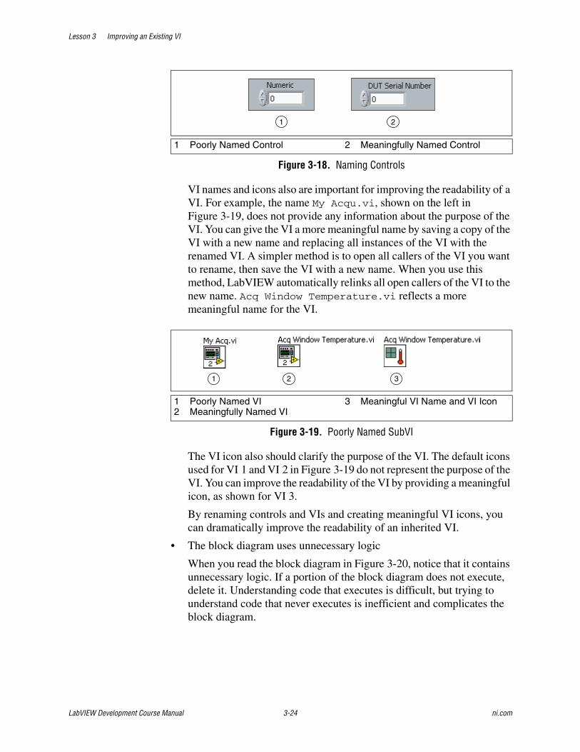
Lesson 3 Improving an Existing VI
LabVIEW Development Course Manual 3-24 ni.com
Figure 3-18. Naming Controls
VI names and icons also are important for improving the readability of a VI. For example, the name My Acqu.vi, shown on the left in Figure 3-19, does not provide any information about the purpose of the VI. You can give the VI a more meaningful name by saving a copy of the VI with a new name and replacing all instances of the VI with the renamed VI. A simpler method is to open all callers of the VI you want to rename, then save the VI with a new name. When you use this method, LabVIEW automatically relinks all open callers of the VI to the new name. Acq Window Temperature.vi reflects a more meaningful name for the VI.
Figure 3-19. Poorly Named SubVI
The VI icon also should clarify the purpose of the VI. The default icons used for VI 1 and VI 2 in Figure 3-19 do not represent the purpose of the VI. You can improve the readability of the VI by providing a meaningful icon, as shown for VI 3.
By renaming controls and VIs and creating meaningful VI icons, you can dramatically improve the readability of an inherited VI.
• The block diagram uses unnecessary logic
When you read the block diagram in Figure 3-20, notice that it contains unnecessary logic. If a portion of the block diagram does not execute, delete it. Understanding code that executes is difficult, but trying to understand code that never executes is inefficient and complicates the block diagram.
1 Poorly Named Control 2 Meaningfully Named Control
1 Poorly Named VI2 Meaningfully Named VI
3 Meaningful VI Name and VI Icon
1 2
1 32

Lesson 3 Improving an Existing VI
© National Instruments Corporation 3-25 LabVIEW Development Course Manual
Figure 3-20. Unnecessary Logic
• The block diagram has duplicated logic
If a VI contains duplicated logic, you always should refactor the VI by creating a subVI for the duplicated logic. This can improve the readability and testability of the VI.
• The block diagram does not use dataflow programming
If there are sequence structures and local variables on the block diagram, the VI probably does not use data flow to determine the programming flow.
You should replace most sequence structures with the state machine design pattern. Delete local variables and wire them directly to the control and indicator. The most acceptable use of local variables is to make a control an indicator.
• The block diagram has complicated algorithms
Complicated algorithms can make a VI difficult to read. Complicated algorithms can be more difficult to refactor because there is a higher probability that the changes introduce errors. When you refactor a complicated algorithm make minor changes and test the code frequently. In some cases you can refactor a complicated algorithm by using built-in LabVIEW functions. For example, the VI in Figure 3-21 checks a user name and password against a database.
Figure 3-21. Complicated Algorithm VI
You could refactor this VI using the built-in functions for searching strings, as shown in Figure 3-22.

Lesson 3 Improving an Existing VI
LabVIEW Development Course Manual 3-26 ni.com
Figure 3-22. Refactored VI
• The block diagram is too big
A VI that has a block diagram that is larger than the screen size is difficult to read. You should refactor the VI to make it smaller. The act of scrolling complicates reading a block diagram and understanding the code. Improve a large block diagram by moving objects around. Another technique to reduce the screen space a block diagram occupies is to create subVIs for sections of code within the block diagram. If you cannot reduce the block diagram to fit on the screen, limit the scrolling to one direction.
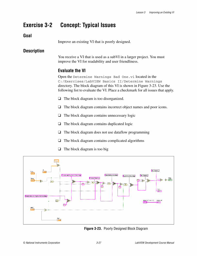
Lesson 3 Improving an Existing VI
© National Instruments Corporation 3-27 LabVIEW Development Course Manual
Exercise 3-2 Concept: Typical Issues
GoalImprove an existing VI that is poorly designed.
DescriptionYou receive a VI that is used as a subVI in a larger project. You must improve the VI for readability and user friendliness.
Evaluate the VIOpen the Determine Warnings Bad One.vi located in the C:/Exercises/LabVIEW Basics II/Determine Warnings directory. The block diagram of this VI is shown in Figure 3-23. Use the following list to evaluate the VI. Place a checkmark for all issues that apply.
❑ The block diagram is too disorganized.
❑ The block diagram contains incorrect object names and poor icons.
❑ The block diagram contains unnecessary logic
❑ The block diagram contains duplicated logic
❑ The block diagram does not use dataflow programming
❑ The block diagram contains complicated algorithms
❑ The block diagram is too big
Figure 3-23. Poorly Designed Block Diagram

Lesson 3 Improving an Existing VI
LabVIEW Development Course Manual 3-28 ni.com
Improve the VIImprove the VI in stages. Begin with the first checkmark: The block diagram is too disorganized.
1. Use the following tips to help you organize the block diagram:
Figure 3-24. Example of a Reorganized Block Diagram
❑ Move all controls to the left of the block diagram.
❑ Move all indicators to the right of the block diagram.
❑ Use the Align Objects and Distribute Objects toolbar buttons to arrange the controls and indicators.
❑ Rearrange wires so that they do not overlap.
❑ Rearrange wires so that no wires are running from right to left.
❑ Reduce the number of bends in wires.
❑ Do not allow wires to run under objects.
2. After the block diagram is better organized, rename controls and indicators using names that are more descriptive.
❑ The purpose of this VI is to determine whether the current temperature and wind speed are at a level requiring a warning to generate. The VI also lights an LED if a warning occurs.
❑ Suggested input names are Current Temperature, Low Temp, High Temp, Current Wind Speed, and High Wind Speed.

Lesson 3 Improving an Existing VI
© National Instruments Corporation 3-29 LabVIEW Development Course Manual
❑ Suggested output names are Warning Text and Warning?.
3. Remove any unnecessary logic from the block diagram.
Figure 3-25 shows an Equal? function followed by a Not function.
Figure 3-25. Unnecessary Logic
You can replace this with a Not Equal? function, completing the same logic with fewer functions, as shown in Figure 3-26.
Figure 3-26. Unnecessary Logic Simplified
You can reduce unnecessary logic even further by using the Boolean input of the Select function, as shown in Figure 3-27.
Figure 3-27. Unnecessary Logic Simplified Further

Lesson 3 Improving an Existing VI
LabVIEW Development Course Manual 3-30 ni.com
Refer to Figure 3-28 for assistance with the wiring this duplicated function that occurs near the end of the VI.
❑ Delete the Equal? function.
❑ Delete the input wire to the Not function.
❑ Wire the input of the Not function to the input wire of the Select function.
❑ Test the edited VI to be sure the functionality has not changed.
Figure 3-28. Example of a Block Diagram with Well-Named Controls and Unnecessary Logic Removed
4. Save the VI as Determine Warnings Good One.vi.
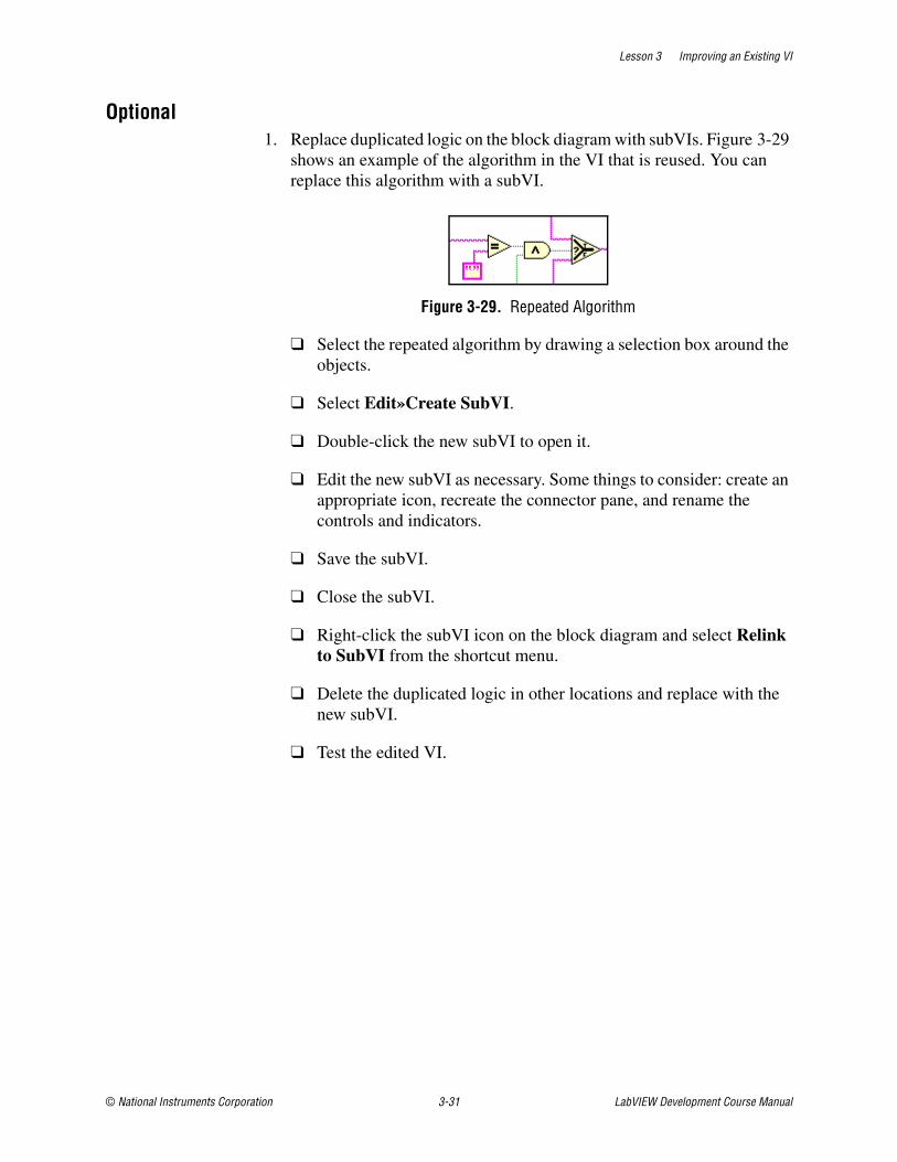
Lesson 3 Improving an Existing VI
© National Instruments Corporation 3-31 LabVIEW Development Course Manual
Optional1. Replace duplicated logic on the block diagram with subVIs. Figure 3-29
shows an example of the algorithm in the VI that is reused. You can replace this algorithm with a subVI.
Figure 3-29. Repeated Algorithm
❑ Select the repeated algorithm by drawing a selection box around the objects.
❑ Select Edit»Create SubVI.
❑ Double-click the new subVI to open it.
❑ Edit the new subVI as necessary. Some things to consider: create an appropriate icon, recreate the connector pane, and rename the controls and indicators.
❑ Save the subVI.
❑ Close the subVI.
❑ Right-click the subVI icon on the block diagram and select Relink to SubVI from the shortcut menu.
❑ Delete the duplicated logic in other locations and replace with the new subVI.
❑ Test the edited VI.

Lesson 3 Improving an Existing VI
LabVIEW Development Course Manual 3-32 ni.com
2. Remove unnecessary local variables and wire to the appropriate control or indicator instead.
Figure 3-30. Example Block Diagram with Duplicated Logic Placed in a SubVI and Local Variables Removed
3. Save the VI as Determine Warnings Good One.vi.
Challenge: Simplify AlgorithmIf you have time remaining in this exercise, try to determine a way to simplify the algorithm and rewrite the code so that is easier to modify later.
An example solution is shown in Figure 3-31 using a state machine. The states contained are: Heatstroke, Freeze, High Wind, and Generate Warning. You can explore this solution Determine Warnings State Machine.vi located in the C:/Exercises/LabVIEW Basics I/Determine Warnings directory. This solution also is used in the course project.

Lesson 3 Improving an Existing VI
© National Instruments Corporation 3-33 LabVIEW Development Course Manual
Figure 3-31. Example Block Diagram with a Simplified Algorithm that is Readable, Maintainable, and Scalable
End of Exercise 3-2

Lesson 3 Improving an Existing VI
LabVIEW Development Course Manual 3-34 ni.com
Job AidUse the following refactoring checklist to help determine if you should refactor a VI. If you answer yes to any of the items in the checklist, refer to the guidelines in the When to Refactor section of this lesson to refactor the VI.
❑ The block diagram is too disorganized.
❑ The block diagram contains incorrect object names and poor icons.
❑ The block diagram contains unnecessary logic.
❑ The block diagram contains duplicated logic.
❑ The block diagram does not use dataflow programming.
❑ The block diagram contains complicated algorithms.
❑ The block diagram is too big.

Lesson 3 Improving an Existing VI
© National Instruments Corporation 3-35 LabVIEW Development Course Manual
Notes

Lesson 3 Improving an Existing VI
LabVIEW Development Course Manual 3-36 ni.com
Notes

© National Instruments Corporation 4-1 LabVIEW Development Course Manual
4Controlling the User Interface
When writing programs, often you must change the attributes of front panel objects programmatically. For example, you may want to make an object invisible until a certain point in the execution of the program. In LabVIEW, VI Server is used to access the properties and methods of front panel objects. This lesson explains the VI Server, Property Nodes, control references, and Invoke Nodes.
Topics
A. VI Server Architecture
B. Property Nodes
C. Control References
D. Invoke Nodes

Lesson 4 Controlling the User Interface
LabVIEW Development Course Manual 4-2 ni.com
A. VI Server ArchitectureThe VI Server is an object-oriented, platform-independent technology that provides programmatic access to LabVIEW and LabVIEW applications. VI Server performs many functions; however, this lesson concentrates on using the VI Server to control front panel objects and edit the properties of a VI and LabVIEW.To understand how to use VI Server, it is useful to understand the terminology associated with it.
Object-Oriented TerminologyObject-oriented programming is based on objects. An object is a member of a class. A class defines what an object is able to do, what operations it can perform (methods), and what properties it has, such as color, size, and so on.
Objects can have methods and properties. Methods perform an operation, such as reinitializing the object to its default value. Properties are the attributes of an object. The properties of an object could be its size, color, visibility, and so on.
Control ClassesLabVIEW front panel objects inherit properties and methods from a class. When you create a Stop control, it is an object of the Boolean class and has properties and methods associated with that class, as shown in Figure 4-1.
Figure 4-1. Boolean Class Example
VI ClassControls are not the only objects in LabVIEW to belong to a class. Your VI belongs to the VI Class and has its own properties and methods associated with it. For instance, you can use VI class methods to abort your VI, to adjust the position of the front panel, and to get an image of the block diagram. You can use VI class properties to change the title of your front panel window, to retrieve the size of the block diagram, and to hide the abort button.
Array Sub-ClassExample Property: Number of Rows
Stop ObjectVisible: YesAttach DataSocket: NoBoolean Text: Stop
Boolean Sub-ClassExample Property: Boolean Text
Control ClassExample Property: VisibleExample Method: Attach DataSocket
Boolean
Stop
Array
Control

Lesson 4 Controlling the User Interface
© National Instruments Corporation 4-3 LabVIEW Development Course Manual
B. Property NodesProperty Nodes access the properties of an object. In some applications, you might want to programmatically modify the appearance of front panel objects in response to certain inputs. For example, if a user enters an invalid password, you might want a red LED to start blinking. Another example is changing the color of a trace on a chart. When data points are above a certain value, you might want to show a red trace instead of a green one. Property Nodes allow you to make these modifications programmatically. You also can use Property Nodes to resize front panel objects, hide parts of the front panel, add cursors to graphs programmatically, and so on.
Property Nodes in LabVIEW are very powerful and have many uses. This section describes examples of specific properties that can change the appearance and function of front panel objects programmatically. Refer to the LabVIEW Help for more information about Property Nodes.
Creating Property NodesWhen you create a Property Node from a front panel object by right-clicking the object, selecting Create»Property Node, and selecting a property from the shortcut menu, LabVIEW creates a Property Node on the block diagram that is implicitly linked to the front panel object.
If the object has an owned label, the Property Node has the same label. You can change the label after creating the node. You also can create multiple Property Nodes for the same object.
Using Property NodesWhen you create a Property Node, it initially has one terminal representing a property you can modify for the corresponding front panel object. Using this terminal on the Property Node, you can either set (write) the property or get (read) the current state of that property.
For example, if you create a Property Node for a digital Numeric control, it appears on the block diagram with the Visible property selected by default. A small arrow appears on the right side of that terminal, indicating that you are reading that property value. You can change the action to write by right-clicking the terminal and selecting Change To Write from the shortcut menu. Wiring a Boolean False to the Visible property terminal causes the numeric control to vanish from the front panel when the Property Node receives the data. Wiring a Boolean True causes the control to reappear.

Lesson 4 Controlling the User Interface
LabVIEW Development Course Manual 4-4 ni.com
Figure 4-2. Using Property Nodes
To get property information, right-click the node and select Change to Read from the shortcut menu. To set property information, right-click the node and select Change to Write from the shortcut menu. If the small direction arrow on the property is on the right, you are getting the property value. If the small direction arrow on a property is on the left, you are setting the property value. If the Property Node in Figure 4-2 is set to Read, when it executes it outputs a Boolean True if the control is visible or a Boolean False if it is invisible.
Tip Some properties are read-only (such as the Label property) or write only, such as the Value (Signaling) property.
To add terminals to the node, right-click and select Add Element from the shortcut menu or use the Positioning tool to resize the node. Then, you can associate each Property Node terminal with a different property from its shortcut menu.
Tip Property Nodes execute each terminal in order from top to bottom.
Some properties use clusters. These clusters contain several properties that you can access using the cluster functions. Writing to these properties as a group requires the Bundle function and reading from these properties requires the Unbundle function. To access bundled properties, select All Elements from the shortcut menu. For example, you can access all the elements in the Position property by selecting Properties»Position»All Elements from the shortcut menu.
However, you also can access the elements of the cluster as individual properties, as shown in Figure 4-3.
Figure 4-3. Properties Using Clusters

Lesson 4 Controlling the User Interface
© National Instruments Corporation 4-5 LabVIEW Development Course Manual
Exercise 4-1 Temperature Limit VI
GoalUse Property Nodes to change the properties of front panel objects programmatically.
ScenarioComplete a VI that records temperature to a waveform graph. During execution, the VI performs the following tasks:
• Set the ∆x value of the chart to the sample rate in seconds.
• Clear the waveform chart so it initially contains no data.
• Change the color of a plot if the data exceed a certain value.
• Make an alarm indicator blink if the data exceed a certain value.
DesignThis VI is already built. You add the following Property Nodes:
Type Name Property
Waveform Chart Temperature XScale.Multiplier
Waveform Chart Temperature History
Waveform Chart Temperature Active Plot 0» Plot.Color
Boolean Indicator (LED) Over Limit Blinking

Lesson 4 Controlling the User Interface
LabVIEW Development Course Manual 4-6 ni.com
Implementation1. Open Temperature Limit.vi located in the C:\Exercises\
LabVIEW Basics II\Temperature Limit directory. The front panel is already built for you.
Figure 4-4. Temperature Limit Front Panel
2. Open the block diagram of the VI. A portion has been built for you. An example of the final block diagram is shown in Figure 4-5.
Figure 4-5. Temperature Limit Block Diagram
3. Modify the VI so that it sets the delta X value of the chart to the sample rate.
❑ Right-click the Temperature terminal and select Create»Property Node»X Scale»Offset and Multiplier»Multiplier from the shortcut menu to create a Property Node.

Lesson 4 Controlling the User Interface
© National Instruments Corporation 4-7 LabVIEW Development Course Manual
❑ Place the new Property Node to the left of the While Loop.
❑ Right-click the Property Node and select Change All To Write from the shortcut menu.
❑ Divide the Sample Rate by 1000 to determine the X-Scale Multiplier, as shown in Figure 4-5.
4. Modify the VI to clear old data from the Temperature chart before starting the temperature acquisition.
Tip To clear a waveform chart from the block diagram, send an empty array of data to the History Data property.
❑ Resize the Property Node to two terminals.
❑ Select the History Data property in the second node.
❑ Right-click the Property Node and select Change All To Write from the shortcut menu.
❑ Right-click the History Data property and select Create»Constant from the shortcut menu.
❑ Place a Flat Sequence structure around the code to enforce execution before the While Loop begins.
❑ Wire the Property Node as shown in Figure 4-5.
5. Modify the VI so that when the VI acquires data, it turns the Data trace red and the Over Limit LED blinks when the temperature exceeds the limit value.
❑ Right-click the Temperature terminal and select Create»Property Node»Active Plot from the shortcut menu to create another Property Node.
❑ Place the new Property Node in the True case of the Case structure.
❑ Resize the node to two terminals.
❑ Click the second node and select Plot»Plot Color.
❑ Right-click the Property Node and select Change All To Write from the shortcut menu.
❑ Wire a numeric constant with a value of 0 to the Active Plot property to select the first plot on the Temperature chart.

Lesson 4 Controlling the User Interface
LabVIEW Development Course Manual 4-8 ni.com
❑ Wire the Red Color Box constant to the Plot Color property to set the plot color to red when the data rises above the High Limit.
❑ Create a copy of the Property Node by pressing <Ctrl> while selecting and dragging the Property Node.
Tip Do not use the clipboard (Edit»Copy) to create a copy of the Property Node. This creates a different type of Property Node that you learn about in the next section.
❑ Place the copy of the Property Node in the False case of the Case structure, as shown in Figure 4-6.
❑ Wire a numeric constant with a value of 0 to the Active Plot property to select the first plot on the Temperature chart.
❑ Connect the Green Color Box constant to the Plot Color property to set the plot color to green when the data is below the High Limit.
Figure 4-6. False Case in the Temperature Limit VI
6. Modify the VI so that when the VI acquires data, the Over Limit LED blinks when the temperature exceeds the limit value.
❑ Right-click the Over Limit terminal and select Create»Property Node»Blinking from the shortcut menu.
❑ Right-click the Property Node and select Change All To Write from the shortcut menu.
❑ Wire the Property Node as shown in Figure 4-5.
7. Save the VI.
Testing1. Run the VI to confirm that it behaves correctly.
2. Close the VI.
End of Exercise 4-1

Lesson 4 Controlling the User Interface
© National Instruments Corporation 4-9 LabVIEW Development Course Manual
C. Control ReferencesA Property Node created from the front panel object or block diagram terminal is an implicitly-linked Property Node. This means that the Property Node is linked to the front panel object. What if you must place your Property Nodes in a subVI? Then the objects are no longer located on the front panel of the VI that contains the Property Nodes. In this case, you need an explicitly-linked Property Node. You create an explicitly-linked Property Node by wiring a reference to a generic Property Node.
If you are building a VI that contains several Property Nodes or if you are accessing the same property for several different controls and indicators, you can place the Property Node in a subVI and use control references to access that node. A control reference is a reference to a specific front panel object.
This lesson shows one way to use control references. Refer to the Controlling Front Panel Objects topic of the LabVIEW Help for more information about control references.
Creating a SubVI with Property NodesAs shown in Figure 4-7, the simplest way to create explicitly-linked Property Nodes is to complete the following steps:
1. Create your VI.
2. Select the portion of the block diagram that is in the subVI, as shown in the first part of Figure 4-7.
3. Select Edit»Create SubVI. LabVIEW automatically creates the control references needed for the subVI.
4. Customize and save the subVI. As you can see in the second part of Figure 4-7, the subVI uses the default icon and connector pane.
Figure 4-7. Using Edit»Create SubVI to Create Control References
Objects Selected to Create SubVI Edit»Create SubVI used

Lesson 4 Controlling the User Interface
LabVIEW Development Course Manual 4-10 ni.com
The subVI created is shown in Figure 4-8. Notice that the front panel Control Refnum controls have been created and connected to a property node on the block diagram.
Figure 4-8. Sub VI Created Using Edit»Create SubVI
Note A red star on the Control Reference control designates that the refnum is strictly typed. Refer to the Strictly Typed and Weakly Typed Control References section of the Controlling Front Panel Objects topic of the LabVIEW Help for more information about weakly and strictly typing.
Creating Control ReferencesTo create a control reference for a front panel object, right-click the object or its block diagram terminal and select Create»Reference from the shortcut menu.
You can wire this control reference to a generic Property Node. You can pass the control reference to a subVI using a control refnum terminal.
Using Control ReferencesSetting properties with the control reference method is useful for setting the same property for multiple controls. Some properties apply to all classes of controls, such as the Disabled property. Some properties are only applicable to certain control classes, such as the Housing Size property, which only applies to Dial and Knob controls.
The following example shows how to construct a VI that uses a control reference on the SubVI to set the Enable/Disable state of a control on the main VI front panel.
Created SubVI Front Panel Created SubVI Block Diagram

Lesson 4 Controlling the User Interface
© National Instruments Corporation 4-11 LabVIEW Development Course Manual
Figure 4-9. Control References
The main VI sends a reference for the digital numeric control to the subVI along with a value of zero, one, or two from the enumerated control. The subVI receives the reference by means of the Ctl Refnum on its front panel. Then, the reference is passed to the Property Node. Because the Property Node now links to the numeric control in the main VI, the Property Node can change properties of that control. In this case, the Property Node manipulates the Enabled/Disabled state.
Notice the appearance of the Property Node in the block diagram. You cannot select a property in a generic property node until the class is chosen. The class is chosen by wiring a reference to the property node. This is an example of an explicitly-linked Property Node. It is not linked to a control until the VI is running and a reference is passed to the property node. The advantage of this type of Property Node is its generic nature. Because it has no explicit link to any one control, it may be reused for many different controls. This generic Property Node is available on the Functions palette.
1 Main VI 2 SubVI
1 2

Lesson 4 Controlling the User Interface
LabVIEW Development Course Manual 4-12 ni.com
Selecting the Control TypeWhen you place a Control Refnum on the front panel of a subVI, you next need to specify the VI Server Class of the control. This specifies the type of control references that the subVI will accept. In the previous example, Control was selected as the VI Server Class type, as shown in Figure 4-9. This allows the VI to accept a reference to any type of front panel control.
However, you can specify a more specific class for the refnum to make the subVI more restrictive. For example, you can select Digital as the class, and the subVI only can accept references to numeric controls of the class Digital. Selecting a more generic class for a control refnum allows it to accept a wider range of objects, but limits the available properties to ones that apply to all objects which the property node can accept.
To select a specific control class, right-click the control and select Select VI Server Class»Generic»GObject»Control from the shortcut menu. Then, select the specific control class you need.

Lesson 4 Controlling the User Interface
© National Instruments Corporation 4-13 LabVIEW Development Course Manual
Exercise 4-2 Set Plot Names
GoalUse control references to create a subVI that modifies graph or chart properties.
ScenarioCreate a subVI that allows you to assign a list of plot names to a chart or graph. The subVI should resize the plot legend as necessary to display all of the plots.
Design
Inputs and Outputs
Control ReferencesThe only class that contains both the Waveform Chart and the Waveform Graph is the GraphChart class. In order to write a subVI that can accept references to both charts and graphs you must use a weakly typed control reference of the GraphChart class. However, this class also contains other charts and graphs, such as the XY Graph. This subVI, generates an error if the user wires any type of graph other than a Waveform Chart or a Waveform Graph. You can determine if the user has wired the correct type by using the ClassName property to control a Case structure. If the correct class is wired, use the To More Specific Class function to get a reference to the appropriate subclass. After you have a reference to a WaveformChart or a WaveformGraph you can set the properties to modify plot names.
Type Name Default Value
Control Reference to a GraphChart object.
Graph Reference N/A
1-D Array of Strings Control Plot Names Empty Array
Error Cluster Control Error In No Error
Error Cluster Indicator Error Out No Error

Lesson 4 Controlling the User Interface
LabVIEW Development Course Manual 4-14 ni.com
PropertiesGraphs and charts do not have a single property to set all of the plot names. Instead you must use a combination of properties to set each plot name. In this exercise, use the following properties and methods:
ClassName—This property returns a string indicating the control class of the object that the property is called on. You can access this property for any control.
LegAutosize—This property controls whether the Graph Legend automatically resizes to accomodate the plot names within it. Before modifying the plot names you should set this property to false. Otherwise, the legend may resize in such a way that it is separated from the graph or covers the graph or other controls.
LegPlots—This property controls the number of plots visible on the Graph Legend. When placing your legend on the front panel, remember to leave room for the legend to expand when you set this property. The legend expands downwards.
ActPlot—Properties affecting a plot act upon one plot at a time. This property controls the active plot. Any time a plot property is set or read it applies to the active plot. The plots are numbered sequentially as they are created, starting with zero.
Plot.Name—This property sets the name of the active plot.

Lesson 4 Controlling the User Interface
© National Instruments Corporation 4-15 LabVIEW Development Course Manual
Implementation1. Open a blank VI.
2. Save as Set Plot Names.vi in the C:\Exercises\LabVIEW Basics II\Set Plot Names directory.
3. Build the front panel.
❑ Place a Control Refnum on the front panel.
❑ Name the Control Refnum Graph Reference.
❑ Right-click Graph Reference and choose Select VI Server Class»Generic»GObject»Control»GraphChart»GraphChart from the shortcut menu.
❑ Place an Array on the front panel.
❑ Name the array Plot Names.
❑ Place a String Control inside the Plot Names array.
❑ Place an Error In cluster.
❑ Place an Error Out cluster.
❑ Arrange the controls as shown in Figure 4-10.
Figure 4-10. Set Plot Names Front Panel
Tip Because the front panel of this subVI is not displayed to the user, you do not have to put as much effort into making it visually appealing. You should always organize your front panels logically. However, you should not spend too much time on panels that the user does not see.
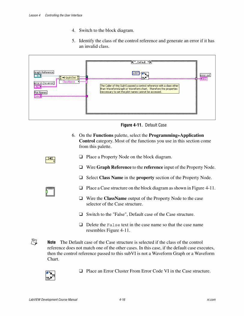
Lesson 4 Controlling the User Interface
LabVIEW Development Course Manual 4-16 ni.com
4. Switch to the block diagram.
5. Identify the class of the control reference and generate an error if it has an invalid class.
Figure 4-11. Default Case
6. On the Functions palette, select the Programming»Application Control category. Most of the functions you use in this section come from this palette.
❑ Place a Property Node on the block diagram.
❑ Wire Graph Reference to the reference input of the Property Node.
❑ Select Class Name in the property section of the Property Node.
❑ Place a Case structure on the block diagram as shown in Figure 4-11.
❑ Wire the ClassName output of the Property Node to the case selector of the Case structure.
❑ Switch to the "False", Default case of the Case structure.
❑ Delete the False text in the case name so that the case name resembles Figure 4-11.
Note The Default case of the Case structure is selected if the class of the control reference does not match one of the other cases. In this case, if the default case executes, then the control reference passed to this subVI is not a Waveform Graph or a Waveform Chart.
❑ Place an Error Cluster From Error Code VI in the Case structure.

Lesson 4 Controlling the User Interface
© National Instruments Corporation 4-17 LabVIEW Development Course Manual
❑ Right-click the error code input of the Error Cluster From Error Code VI and select Create»Constant from the shortcut menu.
❑ Enter 1057 in the constant.
Note Error code 1057 corresponds to the message Object cannot be typecasted to the specified type. This is the appropriate error to generate if the caller of the subVI passes a control reference of the wrong class.
❑ Wire the diagram as shown in Figure 4-11.
7. Handle the WaveformGraph references.
Figure 4-12. WaveformGraph Case
❑ Switch to the "True" case of the case structure.
❑ Change the True text in the case name to WaveformGraph so that the case name resembles Figure 4-12.
❑ Place a To More Specific Class function in the Case structure
❑ Right-click the target class input of the To More Specific Class function and select Create»Constant from the shortcut menu.
❑ Click the Generic Class constant and select the Generic»GObject»Control»GraphChart»WaveformGraph»WaveformGraph class.
❑ Place a Property Node in the Case structure
❑ Wire the specific class reference output of the To More Specific Class function to the reference input of the Property Node.

Lesson 4 Controlling the User Interface
LabVIEW Development Course Manual 4-18 ni.com
❑ Click the Property section of the Property Node and select Legend»Autosize.
❑ Expand the Property Node to display two properties.
❑ Click the second property in the Property Node and select Legend»Plots Shown.
❑ Right-click the Property Node and select Change All To Write from the shortcut menu.
❑ Right-click the LegAutosize property and select Create»Constant from the shortcut menu. Ensure that the value of the constant is False.
❑ Place an Array Size function in the Case structure.
❑ Place a For Loop in the Case structure.
❑ Place a Property Node in the For Loop.
❑ Wire the dup reference output of the first Property Node through the border of the For Loop to the reference input of the second Property Node.
❑ Click the Property section of the Property Node and select Active Plot from the list.
❑ Expand the Property Node to display two properties.
❑ Click the second property in the Property Node and select Plot»Plot Name from the list.
❑ Right-click the Property Node and select Change All To Write from the shortcut menu.
❑ Wire the diagram as shown in Figure 4-12. Use shift registers when wiring the error wires through the For Loop and use Auto Indexing for the Plot Names wire.

Lesson 4 Controlling the User Interface
© National Instruments Corporation 4-19 LabVIEW Development Course Manual
8. Handle WaveformGraph references.
Figure 4-13. WaveformChart Case
❑ Right-click the border of the Case structure and select Duplicate Case from the shortcut menu.
❑ Enter WaveformChart in the case name.
❑ Click the WaveformGraph reference constant and select Generic»GOjbect»Control»GraphChart»WaveformChart.
Note When you change the class of a control reference, all Property and Invoke Nodes using the reference become invalid because the properties refer to a class that does not match the reference. Notice that all of the property names change to black when you change the class reference and that the run arrow is broken. Leave the broken wires alone, because the wires reconnect as you reselect the properties.
❑ Click each of the four properties and select the correct property again. The four properties are Legend»Autosize, Legend»Plots Shown, Active Plot, and Plot»Plot Name. The resulting diagram appears as shown in Figure 4-13.

Lesson 4 Controlling the User Interface
LabVIEW Development Course Manual 4-20 ni.com
9. Build the icon and connector pane for the subVI. Figure 4-14 shows an example icon and connector pane.
Figure 4-14. Connector Pane Connections for Set Plot Names VI
❑ Switch to the front panel of the VI.
❑ Right-click the VI Icon and select Show Connector from the shortcut menu.
❑ Right-click the connector pane and select Patterns from the shortcut menu to choose a pattern.
10. Wire the connector pane.
❑ Right-click the connector pane and select Show Icon from the shortcut menu.
❑ Right-click the icon and select Edit Icon from the shortcut menu.
❑ Use the tools in the Icon Editor to create an icon. If you prefer to use a pre-built icon, select Edit»Import Picture From File and browse to C:\Exercises\LabVIEW Basics II\Set Plot Names\Set Plot Names Icon.bmp. Select Edit»Paste.
❑ Close the Icon Editor when you are finished.
11. Save the VI.
Connections Connector Pane

Lesson 4 Controlling the User Interface
© National Instruments Corporation 4-21 LabVIEW Development Course Manual
Testing1. Test the VI using a Waveform Graph.
Figure 4-15. Set Plot Names Test
❑ Create a blank VI.
❑ Place a Waveform Graph on the front panel.
❑ Open the block diagram.
❑ Right-click the Waveform Graph terminal and select Create»Reference from the shortcut menu.
❑ Drag the icon of the Set Plot Names VI onto the block diagram of the new VI.
❑ Wire the WaveformGraph reference to the Graph Reference input terminal of the Set Plot Names VI.
❑ Right-click the Plot Names input of the Set Plot Names VI and select Create»Control from the shortcut menu. The block diagram should look something like Figure 4-15.
❑ Switch to the front panel of the new VI.
❑ Enter One and Two as items in the Plot Names array.
❑ Move the Plot Legend to the right of the graph so that you can expand the legend.
❑ Run the VI. One and Two appear in the legend.
2. Test the VI using a Waveform Chart.
❑ Right-click the Waveform Graph and select Replace»Graph Indicators»Waveform Chart from the shortcut menu.

Lesson 4 Controlling the User Interface
LabVIEW Development Course Manual 4-22 ni.com
❑ Add Three as another item in the Plot Names array.
❑ Run the VI. Three appears in the legend of the chart.
3. Test the VI with a XY Graph.
❑ Right-click the Waveform Graph and select Replace»Graph Indicators»XY Graph from the shortcut menu.
❑ Add Four as another item in the Plot Names array.
❑ Run the VI. A typecasting error occurs.
4. Close the VI. You do not need to save the VI used for testing the Set Plot Names VI.
End of Exercise 4-2

Lesson 4 Controlling the User Interface
© National Instruments Corporation 4-23 LabVIEW Development Course Manual
D. Invoke NodesUse Invoke Nodes to access the methods of an object.
Use the Invoke Node to perform actions, or methods, on an application or VI. Unlike the Property Node, a single Invoke Node executes only a single method on an application or VI. Select a method by using the Operating tool to click the method terminal or by right-clicking the white area of the node and selecting Methods from the shortcut menu. You also can create an Invoke Node by right-clicking the object, selecting Create»Invoke Node, and selecting a method from the shortcut menu.
The name of the method is always the first terminal in the list of parameters in the Invoke Node. If the method returns a value, the method terminal displays the return value. Otherwise, the method terminal has no value.
The Invoke Node lists the parameters from top to bottom with the name of the method at the top and the optional parameters, which are dimmed, at the bottom.
Example MethodsAn example of a method common to all controls is the Reinitialize to Default method. Use this method to reinitialize a control to its default value at some point in your VI. The VI class has a similar method called Reinitialize All to Default.
Figure 4-16 is an example of a method associated with the Waveform Graph class. This method exports the waveform graph image to the clipboard or to a file.
Figure 4-16. Invoke Node for the Export Image Method

Lesson 4 Controlling the User Interface
LabVIEW Development Course Manual 4-24 ni.com
Exercise 4-3 Front Panel Properties VI
GoalLearn how to affect the attributes of a VI by using Property Nodes and Invoke Nodes.
ScenarioYou can set the appearance properties of a VI statically by using the VI properties page. However, robust user interfaces often must modify the appearance of a front panel while the program runs.
You must create a VI that can perform the following tasks on demand:
• Show or hide its Title Bar
• Show or hide its Menu Bar
• Become transparent so that objects behind the VI can be seen
• Move to the center of the screen

Lesson 4 Controlling the User Interface
© National Instruments Corporation 4-25 LabVIEW Development Course Manual
Design
Inputs and Outputs
Use the vertical toggle switches because their default mechanical action is switch when pressed. Use the OK button because its default action is latch when released.
PropertiesUse the following properties and methods on the VI class:
ShowMenuBar—When this property is true, the Menu bar of the VI is visible.
Figure 4-17. VI Menu Bar
TitleBarVis—When this property is true, the Title bar of the VI is visible.
Figure 4-18. VI Title Bar
RunTransparently—When this property is true, the transparency of the VI can vary. The default value of this property is FALSE, so you must write a TRUE to this property before varying the transparency of the VI.
Transparency—This property varies the transparency of the VI. The property accepts any value between 0 and 100. A value of 0 makes the VI completely opaque (normal behavior), and a value of 100 makes the VI completely transparent (invisible). For this exercise, you set the value to 50 when the Make VI Transparent? button is pressed.
Type Name Default Value
Vertical Toggle Switch Show Menu Bar? True (Yes)
Vertical Toggle Switch Show Title Bar? True (Yes)
Vertical Toggle Switch Make VI Transparent? True (Yes)
OK Button Center False
Stop Button Stop False

Lesson 4 Controlling the User Interface
LabVIEW Development Course Manual 4-26 ni.com
MethodsUnlike properties, a method has an effect every time you call it. Therefore, you should only call methods when you want to perform an action. For example, if you call the Fp.Center method during each iteration of a loop, the VI is continually centered, thereby preventing the user from moving it. You can use a Case structure to control calling the method in a given iteration of a loop. Use the following method on the VI class:
Center—Each time this method is called, the VI moves to the center of the screen.
Tip Use the Context Help window to view descriptions of each properties and methods.
VI StructureThe VI polls the front panel controls every 50 milliseconds and sets the value of the properties based on the current value of the controls. A Case structure controls the execution of the Center method.

Lesson 4 Controlling the User Interface
© National Instruments Corporation 4-27 LabVIEW Development Course Manual
ImplementationIn the following steps, you create the front panel for the VI. An example of the front panel is shown in Figure 4-19.
Figure 4-19. Front Panel Properties VI Front Panel
1. Open a blank VI.
2. Save the VI as Front Panel Properties.VI in the C:\Exercises\LabVIEW Basics II\Front Panel Properties directory.
3. Create the Show Menu Bar? vertical toggle switch.
❑ Place a Vertical Toggle Switch on the front panel.
❑ Name the switch Show Menu Bar?.
❑ Create free labels for the Yes and No states of the switch.
4. Create the Show Title Bar? switch.
❑ Make a copy of the Show Menu Bar? switch.
❑ Rename the switch Show Title Bar?.
❑ Copy the free labels for the Yes and No states from the Show Menu Bar? switch.
5. Create the Make VI Transparent? switch.
❑ Make a copy of the Show Menu Bar? switch.
❑ Rename the switch Make VI Transparent?.
❑ Copy the free labels for the Yes and No states from the Show Menu Bar? switch.
6. Create the Center button.

Lesson 4 Controlling the User Interface
LabVIEW Development Course Manual 4-28 ni.com
❑ Place an OK Button on the front panel
❑ Name the button Center.
❑ Change the Boolean text on the button to Center the VI.
❑ Right-click the button and select Visible Items»Label from the shortcut menu to hide the label.
7. Create the Stop button.
❑ Place a Stop Button on the front panel.
❑ Right-click the button and select Visible Items»Label from the shortcut menu to hide the label.
8. Select Edit»Make Current Values Default.
9. Arrange and organize objects on the front panel. Use the align, distribute, and resize buttons on the toolbar.
10. In the following steps, create the block diagram for the VI. An example of the block diagram is shown in Figure 4-20.
Figure 4-20. Front Panel Properties Block Diagram
Figure 4-21. False Case for Center Method
11. Place a While Loop from the Structures category around the terminals.

Lesson 4 Controlling the User Interface
© National Instruments Corporation 4-29 LabVIEW Development Course Manual
12. Create a reference to the VI.
❑ Place a VI Server Reference on the block diagram to the left of the While Loop.
❑ Set the VI Server Reference to This VI if it is not already.
Note The This VI reference allows you to access all the methods and properties of the current VI without having to explicitly open and close a reference.
13. Create a Property Node for the RunTransparently property.
❑ Right-click the This VI reference and select Create»Property»Front Panel Window»Run VI Transparently from the shortcut menu to create a Property Node.
❑ Move the Property Node to the right of the This VI reference, outside of the While Loop.
❑ Right-click the Property Node and select Change All to Write. from the shortcut menu
❑ Right-click the FP.RunTransparently property and select Create»Constant from the shortcut menu.
❑ Change the value of the constant to True.
14. Create a Property Node for the ShowMenuBar, TitleBarVis, and Transparency properties.
❑ Right-click the This VI reference and select Create»Property»Front Panel Window»Show Menu Bar from the shortcut menu to create another Property Node.
❑ Expand the Property Node to show three elements.
❑ Click the second item in the Property Node and select Front Panel Window»Title Bar Visible.
❑ Click the third item in the Property Node and select Front Panel Window»Transparency.
❑ Right-click the Property Node and select Change All to Write from the shortcut menu.
❑ Move the Property Node inside the While Loop.
❑ Place a Select function inside the While Loop.

Lesson 4 Controlling the User Interface
LabVIEW Development Course Manual 4-30 ni.com
❑ Place two Numeric Constants with values 0 and 50 to the left of the Select function.
❑ Wire the 0 numeric constant to the f terminal of the Select function.
❑ Wire the 50 numeric constant to the t terminal of the Select function.
❑ Wire the Boolean controls to the appropriate properties, as shown in Figure 4-20.
15. Create a Invoke Node for the Center method.
❑ Right-click the This VI reference and select Create»Method»Front Panel»Center from the shortcut menu to create an Invoke Node.
16. Place a Case structure around the FP.Center Invoke Node.
17. Add a 50 ms wait to the loop.
❑ Place a Wait (ms) function in the While Loop.
❑ Right-click the milliseconds to wait input and select Create»Constant from the shortcut menu.
❑ Enter 50 in the constant.
18. Set the While Loop to stop when the user clicks the Stop button or when an error occurs.
❑ Place an Unbundle By Name function in the While Loop.
❑ Place an Or function in the While Loop.
19. Wire the diagram as shown in Figure 4-20 and Figure 4-21. Make sure to replace the error cluster tunnel with a shift register.
20. Display any errors that may occur to the user.
❑ Place a Simple Error Handler to the right of the While Loop.
❑ Wire the Simple Error Handler to the error cluster output shift register from the While loop.
21. Save the VI
Lesson 4 Controlling the User Interface
© National Instruments Corporation 4-31 LabVIEW Development Course Manual
Testing1. Switch to the front panel of the VI.
2. Run the VI.
3. Try each of the buttons and observe the results.
End of Exercise 4-3


Lesson 4 Controlling the User Interface
© National Instruments Corporation 4-33 LabVIEW Development Course Manual
Self-Review: Quiz
1. For each of the following items, determine whether they operate on a VI class or a Control class.
• Format and Precision
• Blinking
• Reinitialize to Default Value
• Show Tool Bar
2. You have a ChartGraph control refnum, shown at left, in a subVI. Which of the following control references could you wire to the control refnum terminal of the subVI? (multiple answers)
a. Control reference of an XY Graph
b. Control reference of a Numeric Array
c. Control reference of a Waveform Chart
d. Control reference of a Boolean


Lesson 4 Controlling the User Interface
© National Instruments Corporation 4-35 LabVIEW Development Course Manual
Self-Review: Quiz Answers
1. For each of the following items, determine whether they operate on a VI class or a Control class.
• Format and Precision: Control
• Blinking: Control
• Reinitialize to Default Value: Control
• Show Tool Bar: VI
2. You have a ChartGraph control refnum, shown at left, in a subVI. Which control references could you wire to the control refnum terminal of the subVI?
a. Control reference of an XY Graph
b. Control reference of a Numeric Array
c. Control reference of a Waveform Chart
d. Control reference of a Boolean

Lesson 4 Controlling the User Interface
LabVIEW Development Course Manual 4-36 ni.com
Notes

© National Instruments Corporation 5-1 LabVIEW Development Course Manual
5Advanced File I/O Techniques
Frequently, the decision to separate the production of data and the consumption of data into separate processes occurs because you must write the data to file as it is acquired. This lesson explains ASCII, Binary and Test Data Exchange (TDM) file formats and when each is a good choice for your application.
Topics
A. File Formats
B. Binary Files
C. TDM Files

Lesson 5 Advanced File I/O Techniques
LabVIEW Development Course Manual 5-2 ni.com
A. File FormatsAt their lowest level, all files written to your computer’s hard drive are a series of binary bits. However, many formats for organizing and representing data in a file are available. In LabVIEW, three of the most common techniques for storing data are the ASCII file format, direct binary storage, and the TDM file format. Each of these formats has advantages and some formats work better for storing certain data types than others.
When to Use Text (ASCII) FilesUse text format files for your data to make it available to other users or applications, if disk space and file I/O speed are not crucial, if you do not need to perform random access reads or writes, and if numeric precision is not important.
Text files are the easiest format to use and to share. Almost any computer can read from or write to a text file. A variety of text-based programs can read text-based files.
Store data in text files when you want to access it from another application, such as a word processing or spreadsheet application. To store data in text format, use the String functions to convert all data to text strings. Text files can contain information of different data types.
Text files typically take up more memory than binary and datalog files if the data is not originally in text form, such as graph or chart data, because the ASCII representation of data usually is larger than the data itself. For example, you can store the number –123.4567 in 4 bytes as a single-precision floating-point number. However, its ASCII representation takes 9 bytes, one for each character.
In addition, it is difficult to randomly access numeric data in text files. Although each character in a string takes up exactly 1 byte of space, the space required to express a number as text typically is not fixed. To find the ninth number in a text file, LabVIEW must first read and convert the preceding eight numbers.
You might lose precision if you store numeric data in text files. Computers store numeric data as binary data, and typically you write numeric data to a text file in decimal notation. A loss of precision might occur when you write the data to the text file. Loss of precision is not an issue with binary files.
When to Use Binary FilesStoring binary data, such as an integer, uses a fixed number of bytes on disk. For example, storing any number from 0 to 4 billion in binary format, such as 1, 1,000, or 1,000,000, takes up 4 bytes for each number.

Lesson 5 Advanced File I/O Techniques
© National Instruments Corporation 5-3 LabVIEW Development Course Manual
Use binary files to save numeric data and to access specific numbers from a file or randomly access numbers from a file. Binary files are machine readable only, unlike text files, which are human readable. Binary files are the most compact and fastest format for storing data. You can use multiple data types in binary files, but it is uncommon.
Binary files are more efficient because they use less disk space and because you do not need to convert data to and from a text representation when you store and retrieve data. A binary file can represent 256 values in 1 byte of disk space. Often, binary files contain a byte-for-byte image of the data as it was stored in memory, except for cases like extended and complex numeric values. When the file contains a byte-for-byte image of the data as it was stored in memory, reading the file is faster because conversion is not necessary.
Datalog FilesA specific type of binary file, known as a datalog file, is the easiest method for logging cluster data to file. Datalog files store arrays of clusters in a binary representation. Datalog files provide efficient storage and random access, however, the storage format for datalog files is complex, and therefore they are difficult to access in any environment except LabVIEW. Furthermore, in order to access the contents of a datalog file, you must know the contents of the cluster type stored in the file. If you lose the definition of the cluster, the file becomes very difficult to decode. For this reason, datalog files are not recommended for sharing data with others or for storing data in large organizations where you could lose or misplace the cluster definition.
When to Use TDM FilesTest Data Exchange Format (TDM) is a hybrid file format that combines Binary storage and XML formatted ASCII data. In a TDM file, the raw numerical data is stored in binary format. This provides the advantages of binary, such as efficient space usage and fast write times. In addition to this data, an XML format stores the structure of the data and information about the data. This allows the information in the file to be easily accessible and searchable. Typically, the binary data and XML data are separated into two files, a .tdm file for the XML data and a .tdx file for the binary data.
TDM files are designed for storing test or measurement data, especially when the data consists of one or more arrays. TDM files are most useful when storing arrays of simple data types such as numbers, strings, or Boolean data. TDM files cannot store arrays of clusters directly. If your data is stored in arrays of clusters, use another file format, such as binary, or break the cluster up into channels and use the structure of the TDM file to organize them logically.

Lesson 5 Advanced File I/O Techniques
LabVIEW Development Course Manual 5-4 ni.com
TDM Files allow you to create a structure for your data. Data within a file is organized into channels. You also can organize channels into channel groups. A file can contain multiple channel groups. Well grouped data simplifies viewing and analysis and can reduce the time required to search for a particular piece of data.
Use TDM files when you want to store additional information about your data. For example, you might want to record include the type of test or measurement, the operator or tester name, serial numbers, UUT numbers for the device tested, or the time of the test and the conditions under which the test or measurement was conducted. TDM files each contain a File object and can contain as many Channel Group and Channel objects as you want. Each of the objects in a file has properties associated with it, which creates three levels of properties that you can use to store data. For example, test conditions are stored at the file level. UUT information is stored at the channel or channel group level. Storing plenty of information about your tests or measurements can make analysis easier, and also allows you to search for specific data sets. Searching for specific files or data sets based upon stored criteria is important when you gather large amounts of data— especially when you may need to share the data with others.
Searching for data in a file based upon one or more conditions is a feature of the TDM data storage format. With most file formats, you must read the entire file into a program and then programatically search for certain fields in the file in order to locate a specific set of data. With a TDM file you can specify a condition when you read data, and the read returns only data that matches that condition. By using multiple reads and merging their results together you can construct complex queries for your data. You can use any property of the TDM File, Channel Group, or Channel as a query condition. Therefore, enter as many properties as possible when logging TDM files. These properties simplify locating data.
Like many binary file formats, only programs specifically designed to recognize and decode them can read TDM files. LabVIEW, LabWindowsTM/CVITM, and DIAdem, and some other NI software can read a TDM file. Save your data in TDM format when you want to access your data with LabVIEW or DIAdem. However, use a more universal format such as ASCII to access your data using other software.

Lesson 5 Advanced File I/O Techniques
© National Instruments Corporation 5-5 LabVIEW Development Course Manual
B. Binary FilesAlthough all file I/O methods eventually create binary files, you can directly interact with a binary file by using the Binary File functions. The following are some of the common functions that interact with binary files.
Open/Create/Replace File—This function opens a reference to a new or existing file for binary files as it does for ASCII Files.
Write Binary File—This function writes binary data to a file. The function works much like the Write to Text File function, but can accept most data types.
Read Binary File—This function reads binary data starting at its current file position. You must specify to the function the data type to read. Use this function to access a single data element or wire a value to the count input. This causes the function to return an array of the specified data type.
Get File Size—This function returns the size of the file in bytes. Use this function in combination with the Read Binary File function when you want to read all of a binary file. Remember that if you are reading data elements that are larger than a byte you must adjust the count to read.
Get/Set File Position—These functions get and set the location in the file where reads and writes occur. Use these functions for Random File Access.
Close File—This function closes an open reference to a file.
Figure 5-1 shows an example that writes an array of doubles to a binary file. Refer to the Arrays section of this lesson for more information about the Prepend array or string size? option.
Figure 5-1. Writing a Binary File

Lesson 5 Advanced File I/O Techniques
LabVIEW Development Course Manual 5-6 ni.com
Binary RepresentationEach LabVIEW data type is represented in a specified way when written to a binary file. The following discusses the representation of each type and important issues when dealing with the binary representation of that type.
Tip A bit is a single binary value. Represented by a 1 or a 0, each bit is either on or off. A byte is a series of 8 bits.
BooleansLabVIEW represents Boolean values as 8-bit values in a binary file. A value of all zeroes represents False. Any other value represents True. This divides files into byte-sized chunks and simplifies reading and processing files. To efficiently store boolean values, convert a series of Boolean values into an integer using the Boolean Array To Number function. Figure 5-2 shows two methods for writing six Boolean values to a binary file.
Figure 5-2. Writing Boolean Values to a Binary File
Table 5-1 displays a binary representation of the file contents resulting from running the program in Figure 5-2. Notice that Method B is a more efficient storage method.
Table 5-1. Results of Figure 5-2.
Method A 00000001 00000001 00000000 00000001 00000000 00000001
Method B 00101011

Lesson 5 Advanced File I/O Techniques
© National Instruments Corporation 5-7 LabVIEW Development Course Manual
8-bit IntegersUnsigned 8-bit integers (U8s) directly correspond to bytes written to the file. When you must write values of various types to a binary file, convert each type into an array of U8s using the Boolean Array To Number, String to Byte Array, Split Number, and Type Cast functions. Then, you can concatenate the various arrays of U8s and write the resulting array to a file. This process is unnecessary when you write a binary file that contains only one type of data.
Other IntegersMulti-byte integers are broken into separate bytes and are stored in files in either little-endian or big-endian byte order. Using the Write to Binary File VI, you can choose whether you store your data in little-endian or big-endian format.
Little-endian byte order stores the least significant byte first, and the most significant byte last. Macintosh computers traditionally used little-endian order and often internally represents data in LabVIEW.
Big-endian order stores the most significant byte first, and the least significant byte last. Most Windows programs use big-endian when storing data to files.
Table 5-2. U8 Representation
Binary Value U8 Value
00000000 0
00000001 1
00000010 2
11111111 255

Lesson 5 Advanced File I/O Techniques
LabVIEW Development Course Manual 5-8 ni.com
Floating Point NumbersFloating point numbers are stored as described by the IEEE 754 Standard for Binary Floating-Point Arithmetic. Single-precision numerics use 32-bits each and double-precision numerics use 64-bits each. The length of extended-precision numerics depends upon the operating system.
StringsStrings are stored as a series of unsigned 8-bit integers, each of which is a value in the ASCII Character Code Equivalents Table. This means that there is no difference between writing strings with the Binary File Functions and writing them with the Text File Functions.
ArraysArrays are represented as a sequential list of each of their elements. The actual representation of each element depends upon the element type. When you store an array to a file you have the option of preceding the array with a header. A header contains a 4-byte integer representing the size of each dimension. Therefore, a 2-dimensional array with a header contains two integers, followed by the data for the array. Figure 5-3 shows an example of writing a two dimensional array of 8-bit integers to a file with a header. The prepend array or string size? terminal of the Write Binary File function enables the header. Notice that the default value of this terminal is True. Therefore, headers are added to all binary files by default.
Table 5-3. Integer Representations
U32 ValueLittle-endian
ValueBig-endian
Value
0 00000000 00000000 00000000 00000000
00000000 00000000 00000000 00000000
1 00000001 00000000 00000000 00000000
00000000 00000000 00000000 00000001
255 11111111 00000000 00000000 00000000
00000000 00000000 00000000 11111111
65535 11111111 11111111 00000000 00000000
00000000 00000000 11111111 11111111
4,294,967,295 11111111 11111111 11111111 11111111
11111111 11111111 11111111 11111111

Lesson 5 Advanced File I/O Techniques
© National Instruments Corporation 5-9 LabVIEW Development Course Manual
Figure 5-3. Writing a 2D Array of Unsigned Integers to a File with a Header
Table 5-4 shows the layout of the file that the code generates in Figure 5-3. Notice that the headers are represented as 32-bit integers even though the data is 8-bit integers.
ClustersDatalog files best represent clusters in binary files. Refer to the Datalog Files section for more information.
Sequential vs. Random AccessWhen reading a binary file, there are two methods of accessing data. The first is to read each item in order, starting at the beginning of a file. This is called sequential access and works similar to reading an ASCII file. The second is to access data at an arbitrary point within the file. For example, if you know that a binary file contains a 1D array of 32-bit integers that was written with a header and you want to access the tenth item in the array, you could calculate the offset in bytes of that element in the file and then read only that element. In this example, the element has an offset of 4 (the header) + 10 (the array index) * 4 (the number of bytes in an I32) = 44. Accessing data in this way is known as random access.
Sequential AccessTo sequentially access all of the data in a file, you can call the Get File Size function and use the result to calculate the number of items in the file, based upon the size of each item and the layout of the file. You can then wire the number of items to the count terminal of the Read Binary function. Figure 5-4 shows an example of this method.
Table 5-4. Example Array Representation In Binary File
4 3 1 2 3 4 5 6 7 8 9 10 11 12

Lesson 5 Advanced File I/O Techniques
LabVIEW Development Course Manual 5-10 ni.com
Figure 5-4. Sequentially Reading an Entire File
Alternately, you can sequentially access the file one item at a time by repeatedly calling the Read Binary function with the default count of 1. Each read operation updates the position within the file so that you read a new item each time read is called. When using this technique to access data you can check for the End of File error after calling Read Binary or calculate the number of reads necessary to reach the end of the file by using Get File Size.
Random AccessTo randomly access a binary file, use the Set Position VI to set the read offset to the point in the file you want to begin reading. Notice that the offset is in bytes. Therefore, you must calculate the offset based upon the layout of the file. In Figure 5-5, the VI returns the array item with the index specified, assuming that the file was written as a binary array of double precision numerics with no header, like the one written by the example in Figure 5-1.
Figure 5-5. Randomly Accessing a Binary File
Datalog FilesDatalog files are designed for storing a list of records to a file. Each record is represented by a cluster, and can contain multiple pieces of data with any data type. Datalog files are binary files, however, they use a different API than other binary files. The Datalog VIs allow you to read and write arrays of clusters to and from Datalog Files.
When you open a Datalog file for either reading or writing you must specify the record type used by the file. To do this, wire a cluster of the appropriate

Lesson 5 Advanced File I/O Techniques
© National Instruments Corporation 5-11 LabVIEW Development Course Manual
type to the Open/Create/Replace Datalog VI. After the file is open, you program Datalog files like any other binary file. Random access is available, although offsets are specified in records instead of bytes.
Figure 5-6 shows an example of writing a datalog file. Notice the cluster both bundles the data and opens the Datalog file.
Figure 5-6. Writing a Datalog File
Figure 5-7 shows an example of randomly accessing a datalog file. Notice that the Record Definition cluster matches the cluster used to write the file. If the record type wired to the Open/Create/Replace Datalog does not match the records in the file being opened, an error occurs.
Figure 5-7. Reading a Datalog File
Instead of using random access, you can read an entire datalog file by wiring the output of the Get Number of Records function to the count terminal of the Read Datalog function.

Lesson 5 Advanced File I/O Techniques
LabVIEW Development Course Manual 5-12 ni.com
Exercise 5-1 Bitmap File Writer VI
GoalUse Binary File I/O to write a file with a specified format.
ScenarioWrite a file storage routine to store image files for an existing LabVIEW-based drawing pad. The drawing pad VI returns a drawing as a 2D array of Red, Green, and Blue (RGB) values. Save the data as a 24-bit bitmap file.
DesignYou can use binary file I/O to write or read data in any file format, assuming that you have a specification that tells you the file layout for that format. The following section describes the format for a 24-bit Windows bitmap file.
24-bit Bitmap File LayoutBitmaps (.bmp) files are a format for storing image data. Bitmaps come in multiple varieties, with differences such as the number of bits used to represent a pixel and the level of image compression used. The easiest type of bitmap file to understand and create is a 24-bit uncompressed bitmap file. A 24-bit uncompressed bitmap file has the following format:
BITMAPFILEHEADER—contains information about the file such as the file type and file size. A subVI calculates the data for this segment. The subVI returns an array of U8 numerics that you must write to the file.
BITMAPINFOHEADER—contains information about the image such as the height, width, compression level, and number of bits per pixel. A subVI calculates the data for this segment. The subVI returns an array of U8 numerics that you must write to the file.
Table 5-5. 24-Bit Bitmap File Layout
Section Name Size(bytes) Notes
BITMAPFILEHEADER 14 Data is provided. Write data to the file.
BITMAPINFOHEADER 40 Data is provided. Write data to the file.
Image Data 3*Number of Pixels Stored in BGR orderImage is inverted.

Lesson 5 Advanced File I/O Techniques
© National Instruments Corporation 5-13 LabVIEW Development Course Manual
Image Data—for a 24-bit image, three bytes represent each pixel in the image. The three bytes represent the Red, Green, and Blue values for the pixel and are stored in reverse order, Blue, Green, and Red. The pixel array you are given is a 2D array of clusters. Each cluster has a Red, Green, and Blue value in it.
The rows in the Image Data are also stored from bottom to top, the first pixel stored is the lower left corner of the image. For this exercise, the pixel array you are given is already vertically inverted so you can write the pixels in the order they are given.
Note The data for each row of the file must have a number of bytes that is divisible by four. You can pad each row with zeroes to bring the number of bytes to a multiple of four. For this exercise all of the pictures returned from the drawing pad have a width that is a multiple of four.
Inputs and OutputsThe main VI for this program contains no inputs and outputs. Dialogs control all user interaction. The Drawing Pad VI displays a dialog that allows the user to draw a picture. When the user clicks Save, prompt them to enter a save location by using a File Dialog VI.
Program Flow1. Call the Drawing Pad VI to attain a picture.
Note The Drawing Pad VI returns the picture as a 2D array of clusters, each containing Red, Green, and Blue values. The two dimensional array has a width that is a multiple of four and is inverted in preparation for writing to file.
2. Display a file dialog to the user to to select a location and file name and open the selected file for writing.
3. Call the BITMAPFILEHEADER VI and pass the dimensions of the pixel array to it.
4. Write the 1D array of unsigned integers returned by the BITMAPFILEHEADER VI to the open file.
Note Disable the prepend array or string size option when you call the Write to Binary File VI, otherwise LabVIEW inserts the array size at the beginning of the data, which invalidates the file layout.
5. Call the BITMAPINFOHEADER VI and pass the dimensions of the pixel array to it.

Lesson 5 Advanced File I/O Techniques
LabVIEW Development Course Manual 5-14 ni.com
6. Write the 1D array of unsigned integers returned by the BITMAPINFOHEADER VI to the open file.
7. Process each pixel in the array by using a pair of For Loops to remove the values from the cluster in Blue, Green, Red order and build them into an array.
Note Use a three dimensional array to store the processed pixel data, as this allow you to use For Loop auto-indexing and simplify the program. The number of dimensions in the array is not important, because the File I/O VIs automatically reformats the array to write to the file.
8. Write the processed pixel array to the open file.
9. Close the file and handle any errors.

Lesson 5 Advanced File I/O Techniques
© National Instruments Corporation 5-15 LabVIEW Development Course Manual
Implementation1. Display the drawing pad.
❑ Create a new VI.
❑ Save the VI as Bitmap File Writer.vi in the C:\Exercises\LabVIEW Basics II\Bitmap File Writer directory.
❑ Open the block diagram.
❑ Place the Drawing Pad VI, located in the C:\Exercises\LabVIEW Basics II\Bitmap File Writer directory, on the block diagram.
❑ Right-click the Drawing Pad VI and select SubVI Node Setup from the shortcut menu.
❑ Check the Show Front Panel when called and Close afterwards if originally closed boxes.
❑ Click OK to exit the SubVI Node Setup dialog.
Note The SubVI node setup lets you specify how to call a SubVI. Checking the Show Front Panel when called box instructs the VI to show its front panel, even if the VI properties would otherwise prevent it from doing so.
❑ Run the VI and observe the drawing pad. Click the Save button to exit. Currently, the program ends when you hit Save, because you have not yet implemented the file I/O.
2. Open a new binary file.
❑ Place a File Dialog Express VI on the block diagram.
❑ Click OK to exit the Configure File Dialog dialog. The default values allow the user to select a single new or existing file.
❑ Configure the File Dialog Express VI to show the selected path, error out, error in, prompt, pattern label, and pattern (all files) terminals by expanding the node and then clicking each item to select a terminal.
❑ Right-click the prompt terminal of the File Dialog Express VI and select Create»Constant from the shortcut menu.
❑ Enter Select File to Save in the string constant.

Lesson 5 Advanced File I/O Techniques
LabVIEW Development Course Manual 5-16 ni.com
❑ Right-click the pattern label terminal of the File Dialog Express VI and select Create»Constant from the shortcut menu.
❑ Enter Bitmap Files in the string constant.
❑ Right-click the pattern(all files) terminal of the File Dialog Express VI and select Create»Constant from the shortcut menu.
❑ Enter *.bmp in the string constant.
❑ Place an Open/Create/Replace File function on the block diagram.
❑ Right-click the operation input of the Open/Create/Replace File function and select Create»Constant from the shortcut menu.
❑ Select replace or create as the value of the constant.
❑ Wire the diagram as shown in Figure 5-8.
Figure 5-8. Open Binary File
3. Create bitmap headers.
❑ Place the BITMAPFILEHEADER VI located in the C:\Exercises\LabVIEW Basics II\Bitmap File Writer directory on the block diagram.
❑ Place the BITMAPINFOHEADER VI located in the C:\Exercises\LabVIEW Basics II\Bitmap File Writer directory on the block diagram.
❑ Place an Array Size function on the block diagram.
❑ Place two Write to Binary File VIs on the block diagram.

Lesson 5 Advanced File I/O Techniques
© National Instruments Corporation 5-17 LabVIEW Development Course Manual
❑ Right-click the prepend array or string size terminal of each Write to Binary File VI and select Create»Constant from the shortcut menu.
❑ Set the constant values to False.
❑ Wire the diagram as shown in Figure 5-9.
Figure 5-9. Write Bitmap Headers
4. Write image data.
❑ Place a For Loop on the block diagram.
❑ Place a second For Loop inside the first For Loop.
❑ Place an Unbundle by Name function in the For Loops.
❑ Place a Build Array function in the For Loops.
❑ Wire the Image Data array through the For Loop borders to the Unbundle By Name function.
❑ Expand the Unbundle by Name function so that three elements are shown.
❑ Choose Blue, Green and Red, in order, for the elements.
Note The bitmap file definition specifies that pixels must be stored in Blue, Green, Red order. Storing the pixels in another order causes the colors in your image to be incorrect.
❑ Place a Write to Binary File VI on the block diagram.

Lesson 5 Advanced File I/O Techniques
LabVIEW Development Course Manual 5-18 ni.com
❑ Right-click the prepend array or string size input of the Write to Binary File VI and select Create»Constant from the shortcut menu. Set the constant value to False.
5. Close file and handle errors.
❑ Place a Close File VI on the block diagram.
❑ Place a Simple Error Handler on the block diagram.
❑ Wire the diagram as shown in Figure 5-10.
6. Save the VI.
Figure 5-10. Complete Block Diagram
Testing1. Run the VI.
❑ Switch to the VI front panel.
❑ Run the VI.
❑ Draw a picture in the drawing pad.
❑ Click Save.
❑ Select C:\Exercises\LabVIEW Basics II\Bitmap File Writer\My Image.bmp as the file to save.

Lesson 5 Advanced File I/O Techniques
© National Instruments Corporation 5-19 LabVIEW Development Course Manual
2. Open the image in an image viewer.
❑ Open the C:\Exercises\LabVIEW Basics II\Bitmap File Writer directory in Windows Explorer.
❑ Double-click the image to open it in your default image viewer. Ensure that the image displayed is the picture you created.
3. Close the VI.
End of Exercise 5-1

Lesson 5 Advanced File I/O Techniques
LabVIEW Development Course Manual 5-20 ni.com
C. TDM FilesIn LabVIEW, you can create TDM Files in two ways. Use the Write to Measurement File and Read from Measurement File Express VIs or the Data Storage API VIs.
The Express VIs allow you to quickly save and retrieve data from the TDM format. Figure 5-11 is the configuration dialog box for the Write to Measurement File Express VI. Notice that you can choose to create a LVM or a TDM file type. However, these Express VIs give you little control over your data grouping and properties and do not allow you to use some of the features that make TDM files useful, such as searching for data based upon conditions.
Figure 5-11. Creating a TDM with Write to Measurement File
To gain access to the full capabilities of TDM files, use the Data Storage API. The Data Storage API is a set of VIs that can write multiple file formats, however, they write TDM files by default. Figure 5-12 is an example of a simple program that logs channel properties and numeric data to a TDM File using the Data Storage API.

Lesson 5 Advanced File I/O Techniques
© National Instruments Corporation 5-21 LabVIEW Development Course Manual
Figure 5-12. Using the Data Storage API to Write a Simple TDM File
Data HierarchyTDM files allow you to organize your data in channel groups and in channels.
A channel group is a segment of a TDM file that contains properties to store information as well as one or more channels. You can use channel groups to organize your data and to store information that applies to multiple channels.
A channel stores measurement signals or raw data in a TDM file. The signal is an array of measurement data. Each channel also can have properties that describe the data. The data stored in the signal is stored as binary data on disk to conserve disk space and efficiency.

Lesson 5 Advanced File I/O Techniques
LabVIEW Development Course Manual 5-22 ni.com
Data Storage API The following are some of the most commonly used Data Storage VIs:
Open Data Storage—opens a reference to a TDM file. You can hard code a file path by using the configuration dialog or determine the path at runtime by using the block diagram terminal.
Figure 5-13. Open Data Storage Dialog Box

Lesson 5 Advanced File I/O Techniques
© National Instruments Corporation 5-23 LabVIEW Development Course Manual
Write Data—allows you to create Channels and Channel Groups within your file. It also allows you to write properties and data for the item you create. The configuration dialog for this VI allows you to select which properties have block diagram terminals and specify how the VI behave if you attempt to store two channels in a file with the same name.
Figure 5-14. Write Data Configuration Dialog Box

Lesson 5 Advanced File I/O Techniques
LabVIEW Development Course Manual 5-24 ni.com
Read Data—allows you to search for Channels or Channel Groups based upon conditions you specify. The configuration dialog for this VI allows you to specify the conditions for the search, as well as the type of data returned when the search result is a channel. This VI can return the actual data signal from a Channel, but in order to access other properties of a Channel or Channel Group pass the references returned from this VI to the Get Properties VI. Notice that because a query can have multiple results, this function returns all of its results, including refnums, in arrays.
Figure 5-15. Read Data Configuration Dialog Box

Lesson 5 Advanced File I/O Techniques
© National Instruments Corporation 5-25 LabVIEW Development Course Manual
Set Properties—this VI allows you to set properties on a Channel, Channel Group, or File. Because the Write Data VI allows you to set the properties of a Channel or Channel Group, this VI is most often used to set File properties. The configuration dialog allows you to select the type of object to set properties for, and the properties to set. You can also use this VI to set the data signal of a Channel. When setting the signal you can choose whether to append the new data to existing data or whether to replace the existing data.
Figure 5-16. Set Properties Configuration Dialog Box

Lesson 5 Advanced File I/O Techniques
LabVIEW Development Course Manual 5-26 ni.com
Get Properties—allows you to access the properties of a File, Channel Group, or Channel. You can combine this VI with the Read Data VI to search for Channels or Channel Groups and then access properties of the search results. You also can use this VI to get all the Channel Groups in a File or all the Channels in a Channel Group. The configuration dialog box allows you to choose which properties you are interested in.
Figure 5-17. Get Properties Configuration Dialog Box
Close Data Storage—closes a reference to a TDM File. Notice that you only must close the File reference, any references that you acquire to Channels and Channel Groups close automatically when you close the File reference.
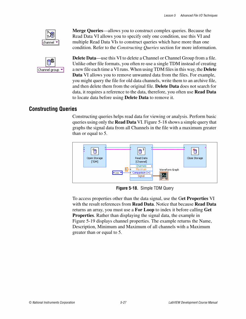
Lesson 5 Advanced File I/O Techniques
© National Instruments Corporation 5-27 LabVIEW Development Course Manual
Merge Queries—allows you to construct complex queries. Because the Read Data VI allows you to specify only one condition, use this VI and multiple Read Data VIs to construct queries which have more than one condition. Refer to the Constructing Queries section for more information.
Delete Data—use this VI to delete a Channel or Channel Group from a file. Unlike other file formats, you often re-use a single TDM instead of creating a new file each time a VI runs. When using TDM files in this way, the Delete Data VI allows you to remove unwanted data from the files. For example, you might query the file for old data channels, write them to an archive file, and then delete them from the original file. Delete Data does not search for data, it requires a reference to the data, therefore, you often use Read Data to locate data before using Delete Data to remove it.
Constructing QueriesConstructing queries helps read data for viewing or analysis. Perform basic queries using only the Read Data VI. Figure 5-18 shows a simple query that graphs the signal data from all Channels in the file with a maximum greater than or equal to 5.
Figure 5-18. Simple TDM Query
To access properties other than the data signal, use the Get Properties VI with the result references from Read Data. Notice that because Read Data returns an array, you must use a For Loop to index it before calling Get Properties. Rather than displaying the signal data, the example in Figure 5-19 displays channel properties. The example returns the Name, Description, Minimum and Maximum of all channels with a Maximum greater than or equal to 5.

Lesson 5 Advanced File I/O Techniques
LabVIEW Development Course Manual 5-28 ni.com
Figure 5-19. Accessing Properties of Query Results
When your TDM file contains data groups, you often want to search for channels only in a particular group. You can do this by using two Read Data VIs: one to search for the appropriate channel group and a second to search for channels within that group. Wiring the reference of the Channel Group to the Read Data VI allows you to constrain the channel search to channels within that group. The example in Figure 5-20 graphs all channels in the Temperature Data group with a maximum greater than 76 degrees. This example assumes only one group with the name Temperature Data exists. This is a valid assumption unless you checked the Always Create new channel group/channel option when you wrote the data with the Write Data VI. If you cannot guarantee that only one Channel Group matches your query, step through the query results using a For Loop like the example in Figure 5-19.
Figure 5-20. Query Data from a Channel Group

Lesson 5 Advanced File I/O Techniques
© National Instruments Corporation 5-29 LabVIEW Development Course Manual
To construct complex TDM queries, use the Merge Queries VI. This VI allows you to combine the results of two Read Data VIs. When you use Merge Queries, you can return results that are in the first query and the second query or combine the results of both queries. After calling Merge Queries, you often call Get Properties to access the signals or properties of the query results.
Grouping DataCarefully consider the best way to group your data as the data grouping can have a significant impact on both the execution speed and implementation complexity of writes and queries. Consider the original format of your data and how you want to search or view the data when choosing a grouping scheme.
One grouping technique is to group data by the type of data. For example, you might put numeric data in one channel group and string data in another, or you might put time domain data in one group and frequency domain data in another. This makes it easy to compare the channels in a group, but can make it difficult to find two channels that are related to each other. Figure 5-21 shows an example of grouping by the type of data. In this example, the temperature data is placed in one group and the wind data is placed in another. Each group contains multiple channels of data. Notice that when grouping by data type you typically have a fixed number of groups, two in this case, and a dynamically determined number of channels. Exercise 5-2 is also an example of grouping by data type.

Lesson 5 Advanced File I/O Techniques
LabVIEW Development Course Manual 5-30 ni.com
Figure 5-21. Grouping by Data Type
Another grouping technique is to group related data. For example, you might put all of the data that applies to a single Unit Under Test (UUT) in one group. Grouping related data allows you to easily locate all of the related data about a particular subject, but makes it harder to compare individual pieces of data between subjects. Relational grouping helps convert cluster-based storage to a TDM format. You can store all of the information from a given cluster in a channel group, with arrays in the cluster being channels within the group, and scalar items in the cluster being properties of the channel group. Figure 5-22 shows an example of grouping related data. Notice that the input data is an array of clusters, each of which contains multiple pieces of information about a test. Each test is stored as a separate Channel Group. Information that applies to the entire test, such as the Test ID and Test Status, is stored as properties of the Channel Group. Arrays of data, such as the time data and power spectrum, are stored in Channels, and information which relates to the arrays of data, such as the RMS Value and Fundamental Frequency, are stored as properties of the channels. Notice that when grouping related data, there is typically a fixed number of channels in a group, but the number of groups is dynamic.

Lesson 5 Advanced File I/O Techniques
© National Instruments Corporation 5-31 LabVIEW Development Course Manual
Figure 5-22. Grouping Related Data

Lesson 5 Advanced File I/O Techniques
LabVIEW Development Course Manual 5-32 ni.com
Exercise 5-2 TDM Logger VI
GoalLog data to a TDM File.
ScenarioYou are given a subVI (Generate Data VI) that generates measurement data for Units Under Test (UUTs). The UUT measurement data consists of a time domain waveform and the power spectrum of the waveform.
Create a VI that accepts an arbitrary number of UUTs, identified by serial numbers, retrieves the measurement data from Generate Data VI, and logs the UUT data and additional properties to a TDM file.
The TDM File is titled TDM Exercise Data and contains the author, timestamp, and two channel groups: Time Data and Power Spectrum Data. Each group contains a channel for each UUT. The serial number of the UUT names each channel and contains the matching signal data.
Design
Program Flow1. Read UUT serial numbers.
Read the UUT serial numbers from an array of string controls on the user interface.
2. Set Time Data chart plots names.
Use the UUT serial number to assign a name to each plot on the Time Data chart indicator using the Set Plot Names VI (written in Exercise 3-3).
3. Set Power Spectrum chart plots names.
Use the UUT serial number to assign a name to each plot on the Power Spectrum chart indicator using the Set Plot Names VI.
4. Determine the number of UUTs.
Use the Array Size function to measure the size of the array used to indicate the UUT serial numbers. The size of the array indicates the number of UUTs.
5. Generate test data.
Use the Generate Data VI to generate time and power spectrum data for each UUT.
6. Create or open a TDM File.
7. Set File Properties.

Lesson 5 Advanced File I/O Techniques
© National Instruments Corporation 5-33 LabVIEW Development Course Manual
Add the title, time stamp and author properties to the file.
8. Write data and properties to file.
Create a subVI (Write Group VI) that writes the channel group, properties, and channels to the file. Refer to the Write Group VI section for details on this subVI.
9. Close the file.
10. Display the data.
Write Group VIThis subVI creates a channel group with a specified name. The channel group contains channels specified by serial numbers. The channel group is written to a TDM file.
This subVI is created because two channel groups are required: Time Data and Power Spectrum Data. Creating a subVI allows you to write the code once and use it multiple times.
The following table contains the controls and indicators used in the subVI.
TDM File Reference Information• File Level Information
• Time Stamp—contains the current time.
• Title—contains the string TDM Exercise Data, identifying the type of test being performed.
• Author—contains the test operator name, acquired through a front panel control.
• The file contains two channel groups, one for time data and one for the power spectrum data.
Input/Output Type Name
Generic Refnum Control storage refnum (file)
String Control Group Name
1-D Array of String Controls UUT Serial Numbers
1-D Array of Waveform Controls. Plots
Error In Control Error In
Generic Refnum Indicator storage refnum out
Error Out Indicator Error Out

Lesson 5 Advanced File I/O Techniques
LabVIEW Development Course Manual 5-34 ni.com
• Channel Group Level Information
• Name—contains Time Data or Power Spectrum Data. This identifies the channel group.
• Each channel group should contain a channel for each UUT.
• Channel Level Information
• Name—contains the UUT Serial Number. This allows you to associate the numeric data with a particular unit.
• Signal—contains an array of floating-point numeric data.
• A number of other properties, such as the signal minimum and maximum will automatically be calculated and added to the file.
Implementation
1. Open TDM Logger.vi in the C:\Exercises\LabVIEW Basics II\TDM Logger directory. The front panel is built for you.
2. Switch to the block diagram.
3. Populate the graph legends with the UUT serial numbers.
Figure 5-23. Set TDM Logger Legend Names
❑ Place two copies of the Set Plot Names VI located in C:\Exercises\LabVIEW Basics II\Set Plot Names directory.
Note If you did not complete the Set Plot Names exercise, you can use the Set Plot Names VI located in the C:\Exercises\LabVIEW Basics II\Exercise 2-2 directory.
❑ Right-click the Time Data indicator terminal and select Create»Reference from the shortcut menu.

Lesson 5 Advanced File I/O Techniques
© National Instruments Corporation 5-35 LabVIEW Development Course Manual
❑ Right-click the Power Spectrum indicator terminal and select Create»Reference from the shortcut menu.
❑ Wire the diagram as shown in Figure 5-23.
4. Test the graph legends.
❑ Switch to the front panel of the VI.
❑ Enter one or more serial numbers in the UUT Serial Number array.
❑ Run the VI. The serial numbers you entered should be displayed in both graph legends.
Tip Always look for opportunities to test your VIs as you are writing them. Debugging is much harder if you write the entire VI and then test it.
5. Place a String control on the front panel and label it Test Operator.
6. Generate and display the test data.
Figure 5-24. Generate and Display Test Data
❑ Switch to the block diagram.
❑ Place the Generate Data VI from the C:\Exercises\LabVIEW Basics II\TDM Logger directory.
❑ Place an Array Size function on the block diagram.
❑ Wire the diagram as shown in Figure 5-24.
❑ Switch to the front panel.

Lesson 5 Advanced File I/O Techniques
LabVIEW Development Course Manual 5-36 ni.com
❑ Right-click the Time Data graph and select Ignore Attributes from the shortcut menu.
❑ Right-click the Power Spectrum graph and select Ignore Attributes from the shortcut menu.
Note You must ignore the attributes of the waveform, otherwise the waveform name attribute would overwrite the labels you set. This option is only available after you wire a waveform to the graph.
7. Test the VI. The graphs should display a plot for each serial number you enter.
8. Open the TDM File.
❑ Place an Open Data Storage VI on the block diagram.
❑ Leave the options at their default settings.
❑ Click OK to exit the Configure Open Data Storage dialog.
9. Set file properties.
Figure 5-25. Set File Properties
❑ Place a Set Properties VI on the block diagram.
❑ Wire the storage refnum(file) output of the Open Data Storage VI to the storage refnum (channel) input of the Set Properties VI.
Note By default, the Set Properties VI is configured to set channel properties. Wiring the file refnum to it causes it to adapt so that it sets file properties instead.
❑ Double-click the Set Properties VI to open the configuration dialog.

Lesson 5 Advanced File I/O Techniques
© National Instruments Corporation 5-37 LabVIEW Development Course Manual
❑ Modify the configuration to match Figure 5-26.
❑ Click OK to close the dialog.
Note The Configure Set Properties dialog lists all of the available properties for the object you have wired to the Set Properties VI. Each of the properties provided is merely a container which can be used in any way you see fit. For example, you could choose to use the Description field to enter the type of test rather than the Title field.
Figure 5-26. Configure Set Properties Dialog Box
❑ Right-click the Title terminal of the Set Properties VI and select Create»Constant from the shortcut menu. Enter TDM Exercise Data as the value of the constant.
❑ Place a Get Date/Time In Seconds function on the block diagram.
❑ Wire the diagram as shown in Figure 5-25.

Lesson 5 Advanced File I/O Techniques
LabVIEW Development Course Manual 5-38 ni.com
Figu
re 5
-27.
Writ
e Da
ta C
hann
els
with
Rep
eate
d Co
de S
elec
ted

Lesson 5 Advanced File I/O Techniques
© National Instruments Corporation 5-39 LabVIEW Development Course Manual
10. Create the Time Data channel group.
❑ Place a Write Data VI on the block diagram.
❑ Select Channel Group from the Object type pull-down menu of the Configure Write Data dialog box.
❑ Rearrange the Properties so that the Selected properties contain Name.
❑ Click OK to close the dialog.
❑ Right-click the Name terminal of the Write Data [Channel group] VI and select Create»Constant from the shortcut menu.
❑ Enter Time Data in the string constant.
11. Write the Time Data channels.
❑ Place a For Loop on the block diagram.
❑ Place a Write Data VI inside the For Loop.
❑ Check the Always create new channel group/channel box in the Configure Write Data dialog box.
Note Selecting this property prevents you from overwriting or appending data if you have more than one channel with the same serial number in a file.
❑ Rearrange the Properties so that the Selected properties contain Name.
❑ Click the OK button to exit the dialog box.
12. Wire the diagram as shown in Figure 5-27.
13. Create a subVI out of the code to write the channel group and channel so you can re-use it to write the power spectrum data.
❑ Select the Write Data VI and the For Loop as shown in Figure 5-27. Do not select the Time Data string constant.
❑ Select Edit»Create SubVI.
❑ Double-click the new subVI to open it.
❑ Save the subVI as C:\Exercises\LabVIEW Basics II\TDM Logger\Write Group.vi.

Lesson 5 Advanced File I/O Techniques
LabVIEW Development Course Manual 5-40 ni.com
❑ Open the block diagram of the subVI.
❑ Right-click the right shift register on the For Loop and select Create»Indicator from the shortcut menu to create an error indicator.
❑ Right-click the storage refnum (file) output of the Write Data [Channel Group] VI and select Create»Indicator from the shortcut menu.
❑ Modify the terminal names and arrange the block diagram as shown in Figure 5-28.
Figure 5-28. Write Data Block Diagram
❑ Switch to the front panel.
❑ Rename the error out control error in.
Note When you select Edit»Create SubVI, the controls and indicators inherit labels from the names associated with the wires they link to in the main VI. Therefore, the error input in this subVI is named error out. However, always name the error cluster control error in and the error cluster indicator error out.
❑ Arrange the controls logically.
❑ Right-click the VI Icon and select Edit Icon from the shortcut menu.
❑ Double-click the Selection Tool to select the entire icon.
❑ Select Edit»Import Picture From File and browse to C:\Exercises\LabVIEW Basics II\TDM Logger\Write Group Icon.bmp.
❑ Select Edit»Paste.

Lesson 5 Advanced File I/O Techniques
© National Instruments Corporation 5-41 LabVIEW Development Course Manual
❑ Click the 16 Colors Icon.
❑ Click the 256 Colors button under the Copy from section.
❑ Click the B&W Icon.
❑ Click the 256 Colors button under the Copy from section.
❑ Click OK.
❑ Right-click the VI Icon and select Show Connector from the shortcut menu.
❑ Create the connector pane as shown in Figure 5-29
❑ Save and close the VI.
❑ Right-click the Write Data VI on the block diagram of the TDM Logger VI and select Relink to SubVI from the shortcut menu.
Figure 5-29. Connector Pane Connections for Write Group VI
Connections Connector Panes

Lesson 5 Advanced File I/O Techniques
LabVIEW Development Course Manual 5-42 ni.com
Figu
re 5
-30.
TDM
Log
ger C
ompl
ete
Bloc
k Di
agra
m

Lesson 5 Advanced File I/O Techniques
© National Instruments Corporation 5-43 LabVIEW Development Course Manual
14. Write the Power Spectrum data.
❑ Place a copy of the Write Group SubVI.
❑ Place a String Constant with the value Power Spectrum.
15. Close the TDM file and handle errors.
❑ Place a Close Data Storage VI on the block diagram.
❑ Place a Simple Error Handler VI on the block diagram.
❑ Wire the diagram as shown in Figure 5-30.
❑ Save the VI.
Testing1. Run the VI.
❑ Ensure that the default value of the TDM File Path control is C:\Exercises\LabVIEW Basics II\TDM Logger\Test Data.TDM.
❑ Enter your name in the Test Operator field.
❑ Enter A001, A002, and A003 in the UUT Serial Numbers control.
❑ Run the VI.
2. Open the data in DIAdem.
Tip NI DIAdem is an interactive tool for mathematical and visual data analysis, and report generation. This tool is a separate product and is not a part of LabVIEW. If you do not have access to DIAdem, you can use the Data Viewer VI to confirm that your data was saved successfully. This VI is an example program that you can locate by searching for TDM in the LabVIEW Example Finder.
❑ Open National Instruments DIAdem by selecting Start»Programs»National Instruments»DIAdem 9.1»DIAdem.
❑ Click the Next > button to begin the DIAdem Report Wizard.
❑ Select FILES: My Computer from the Data sources list if it is not already selected.
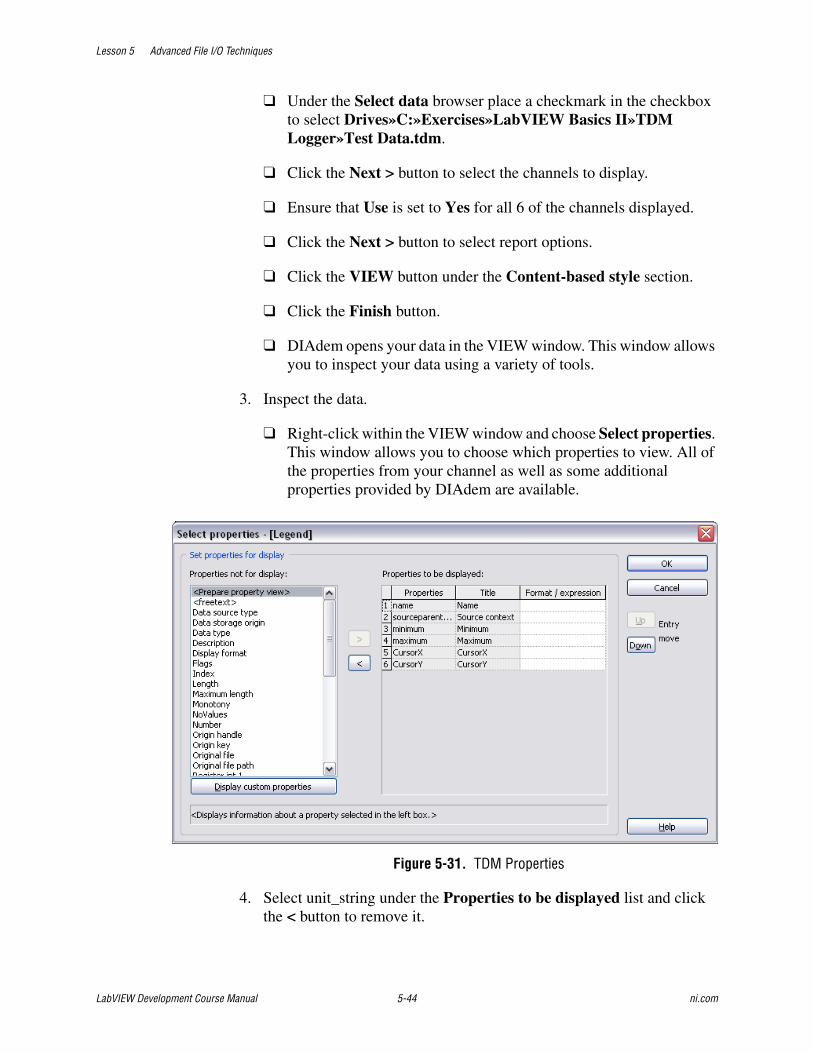
Lesson 5 Advanced File I/O Techniques
LabVIEW Development Course Manual 5-44 ni.com
❑ Under the Select data browser place a checkmark in the checkbox to select Drives»C:»Exercises»LabVIEW Basics II»TDM Logger»Test Data.tdm.
❑ Click the Next > button to select the channels to display.
❑ Ensure that Use is set to Yes for all 6 of the channels displayed.
❑ Click the Next > button to select report options.
❑ Click the VIEW button under the Content-based style section.
❑ Click the Finish button.
❑ DIAdem opens your data in the VIEW window. This window allows you to inspect your data using a variety of tools.
3. Inspect the data.
❑ Right-click within the VIEW window and choose Select properties. This window allows you to choose which properties to view. All of the properties from your channel as well as some additional properties provided by DIAdem are available.
Figure 5-31. TDM Properties
4. Select unit_string under the Properties to be displayed list and click the < button to remove it.

Lesson 5 Advanced File I/O Techniques
© National Instruments Corporation 5-45 LabVIEW Development Course Manual
❑ Select Source context from the Properties not for display list and press the > button to move it to Properties to be displayed. The Source context displays the group that each channel belongs to.
❑ Select Minimum and Maximum from the Properties not for display list and press the > button to move them to Properties to be displayed. These property display the minimum and maximum value in your channels, they were automatically added to your TDM file by LabVIEW when you logged the channel.
❑ Select CursorX and CursorY from the Properties not for display list and press the > button to move them to Properties to be displayed. These property display the values of the cursor in the DIAdem data view.
❑ Click OK to exit the Select Properties dialog. The group name, minimum and maximum values appear for each channel.
Figure 5-32. DIAdem VIEW Window

Lesson 5 Advanced File I/O Techniques
LabVIEW Development Course Manual 5-46 ni.com
❑ Right-click one of the graphs in the VIEW window and select Cursor»Curve. This locks the cursor (crosshair) onto the plots. Observe that the X and Y values are now filled in for each channel.
❑ Place your mouse over the cursor on the top plot and then click and drag the cursor to the left and right. Observe the changing values of the X and Y properties. You can change the plot that the cursor appears on by clicking in the colored box associated with that plot.
Optional: Generate a Report with DIAdem5. Select File»Transfer to REPORT. This will transfer the data to the
REPORT view, where you can create a customized report.
❑ Double-click the plot legend to bring up the 2D graphics legend dialog.
❑ Select Channel name (origin short) from the Labeling with drop-down menu.
❑ Click OK to exit the dialog.
❑ Resize the graph and the legend so that the legend items are next to their respective plots.
❑ Right-click Sheet 1 on the bar at the bottom of the screen and select Delete. Choose OK to delete the worksheet when prompted. You must delete this empty worksheet so that it does not show up in your report.
❑ Select File»PDF Export.
❑ Enter C:\Exercises\LabVIEW Basics II\TDM Logger\Test Data Report.pdf as the path name for the report.
❑ Open the C:\Exercises\LabVIEW Basics II\TDM Logger directory in Windows Explorer and double-click Test Data Report to open it.
❑ Close DIAdem. Do not save any changes.
End of Exercise 5-2

Lesson 5 Advanced File I/O Techniques
© National Instruments Corporation 5-47 LabVIEW Development Course Manual
Exercise 5-3 TDM Query
GoalQuery a TDM file to access information about a specific channel.
ScenarioSaving data to a file serves no purpose unless you also implement or devise a way to access the data. Write a reader to access data from the TDM Logger you implemented in Exercise 5-2. The reader can search for a particular serial number and return either the time data or power spectrum data for that particular serial number.
Design
TDM Query Inputs and Outputs
Because the data in the file is grouped by data type, begin by opening the file and querying for the appropriate channel group. Then, query the channel group to locate the specified serial number. Display the data and close the file when the query is complete.
Table 5-6. TDM Query VI Inputs and Outputs
Type Name Properties
File Path Control TDM File Path Default Value = C:\Exercises\LabVIEW Basics II\TDM Logger\Test Data.TDM
String Control Serial Number
Combo Box Data Set Item 1 = "Time Data"Item 2 = "Power Spectrum"
Waveform Graph Indicator Query Result

Lesson 5 Advanced File I/O Techniques
LabVIEW Development Course Manual 5-48 ni.com
Implementation1. Create a blank VI.
2. Save the VI as C:\Exercises\LabVIEW Basics II\TDM Query\TDM Query.vi.
3. Build the VI front panel.
Figure 5-33. TDM Query Front Panel
❑ Create the TDM File Path control with a default value of C:\Exercises\LabVIEW Basics II\TDM Logger\Test Data.TDM.
❑ Create the Serial Number string control.
❑ Create the Query Result waveform graph.
❑ Place a Combo Box control on the front panel. Label the combo box Data Set.
❑ Right-click the Data Set control and select Edit Items from the shortcut menu.
❑ Enter Power Spectrum in the Items list.
❑ Click the Insert button.
❑ Enter Time Data in the Items list.
❑ Remove the checkmark from the Allow undefined values at run time box.
❑ Click OK.

Lesson 5 Advanced File I/O Techniques
© National Instruments Corporation 5-49 LabVIEW Development Course Manual
❑ Select Time Data from the drop-down menu of the Data Set control.
❑ Right-click the Data Set control and select Data Operations»Make Current Value Default from the shortcut menu.
❑ Arrange the front panel as shown in Figure 5-33.
4. Open the TDM file.
❑ Place an Open Data Storage VI on the block diagram.
❑ Select open (read only) from the Overwrite options pull-down menu.
Tip Opening a file with the open (read only) option increases the speed of reads and searches in the file. Also, it does not lock the file so that other programs can use it at the same time.
❑ Click OK to exit the Configure Open Data Storage dialog box. Leave the default values for the other settings.
❑ Wire the TDM File Path control to the file path input of the Open Data Storage VI.
5. Query for the correct Channel Group.
❑ Place a Read Data VI on the block diagram.
❑ Select Channel Group from the Object type to read drop-down menu.
❑ Select Name from the Property to compare drop-down menu. The dialog box should now resemble Figure 5-34.

Lesson 5 Advanced File I/O Techniques
LabVIEW Development Course Manual 5-50 ni.com
Figure 5-34. Configure Read Data for Channel Groups
❑ Click OK to exit the dialog box.
❑ Place an Index Array function on the block diagram.
Note The Read Data VI returns an array of Channel Group references because more than one Channel Group may match the condition. In this case, you know that only one Channel Group with the given name is present in the file, so you can just use the first item in the array. If it is possible for your query to return more than one Channel Group, you should use a For Loop to process each reference.
❑ Wire the diagram as shown in Figure 5-35.
Figure 5-35. Query Channel Groups
6. Query for the requested Channel data.

Lesson 5 Advanced File I/O Techniques
© National Instruments Corporation 5-51 LabVIEW Development Course Manual
❑ Place a Read Data VI on the block diagram.
❑ Select Name from the Property to compare drop-down menu.
❑ Click OK to exit the dialog box, leave the default values for the other settings.
7. Close the file and handle errors.
❑ Place a Close Data Storage VI on the block diagram.
❑ Place a Simple Error Handler VI on the block diagram.
❑ Wire the block diagram as shown in Figure 5-36.
❑ Save the VI.
Figure 5-36. TDM Query Completed Block Diagram
Testing1. Query for time domain data.
❑ Switch to the VI front panel.
❑ Ensure that the default TDM File Path matches Table 5-6 and the Data Set is set to Time Data.
❑ Enter A001 in the Serial Number control.
Note A001 was one of the serial numbers you entered when you ran the TDM Logger VI in Exercise 5-2.
❑ Run the VI. A sine wave should display in the Query Result graph.
❑ Change the Serial Number to A002.

Lesson 5 Advanced File I/O Techniques
LabVIEW Development Course Manual 5-52 ni.com
❑ Run the VI. A different sine wave should display.
2. Query for power spectrum data.
❑ Change the Data Set control to Power Spectrum.
❑ Run the VI. Power spectrum data should display in the Query Result graph.
End of Exercise 5-3

Lesson 5 Advanced File I/O Techniques
© National Instruments Corporation 5-53 LabVIEW Development Course Manual
Self-Review: Quiz
1. You must store the results of tests to a file. In the future, you must efficiently search for the tests which meet specific criteria. Which file storage format makes it easiest to query the data?
a. Tab-delimited ASCII
b. Custom binary format
c. TDM
d. Datalog
2. You must write a program which saves Portable Network Graphics (PNG) image files. Which file storage VIs should you use?
a. Storage file VIs
b. Binary file VIs
c. ASCII file VIs
d. Datalog file VIs
3. You must store data that other engineers must analyze with Microsoft Excel. Which file storage format should you use?
a. Tab-delimited ASCII
b. Custom binary format
c. TDM
d. Datalog
4. Which of the following is a little-endian representation of an unsigned 32-bit integer (U32) with a value of 10?
a. 00001010 00000000 00000000 00000000
b. 00000000 00000000 00000000 00001010
c. 00001010
d. 01010000 00000000 00000000 00000000
5. You can use the Binary File VIs to read ASCII files.
a. True
b. False
6. TDM Files store all properties at the channel or channel group level.
a. True
b. False


Lesson 5 Advanced File I/O Techniques
© National Instruments Corporation 5-55 LabVIEW Development Course Manual
Self-Review: Quiz Answers
1. You must store the results of tests to a file. In the future, you need to efficiently search for the tests which meet specific criteria. Which file storage format makes it easiest to query the data?
a. Tab-delimited ASCII
b. Custom binary format
c. TDM
d. Datalog
2. You must write a program which saves Portable Network Graphics (PNG) image files. Which file storage VIs should you use?
a. Storage file VIs
b. Binary file VIs
c. ASCII file VIs
d. Datalog file VIs
3. You need to store data which other engineers must analyze with Microsoft Excel. Which file storage format should you use?
a. Tab-delimited ASCII
b. Custom binary format
c. TDM
d. Datalog
4. Which of the following is a little endian representation of an unsigned 32-bit integer (U32) with a value of 10?
a. 00001010 00000000 00000000 00000000
b. 00000000 00000000 00000000 00001010
c. 00001010
d. 01010000 00000000 00000000 00000000
5. You can use the Binary File VIs to read ASCII files.
a. True
b. False
6. TDM Files store all properties at the channel or channel group level.
a. True
b. False

Lesson 5 Advanced File I/O Techniques
LabVIEW Development Course Manual 5-56 ni.com
Notes

© National Instruments Corporation 6-1 LabVIEW Development Course Manual
6Creating and Distributing Applications
This lesson describes the process of creating a stand-alone application and installer for your LabVIEW applications.
Topics
A. LabVIEW Features for Project Development
B. Preparing the Application
C. Building the Application and Installer

Lesson 6 Creating and Distributing Applications
LabVIEW Development Course Manual 6-2 ni.com
A. LabVIEW Features for Project DevelopmentLabVIEW provides several features you can use to manage your projects more efficiently.
VI HistoryOne of the most useful LabVIEW tools for team-oriented development is the History window. Use the History window in each VI to display the development history of the VI, including revision numbers. The revision number starts at zero and increases incrementally every time you save the VI. Record and track the changes you make to the VI in the History window as you make them. Select Edit»VI Revision History to display the History window. You also can print the revision history.
Use the VI Properties Revision History dialog box to set options for the current VI. Use the Options dialog box to set options for all new VIs.
VI HierarchySaving memory is an important advantages of separating your main application into subVIs. In addition, the responsiveness of the LabVIEW editor improves because smaller VIs are easier to handle. Using subVIs makes the high-level block diagram easy to read, debug, understand, and maintain.
Therefore, try to keep the block diagram for your top-level VI under 500 KB in size. In general, keep your subVIs a smaller size. To check the size of a VI, select File»VI Properties and select Memory Usage from the category pull-down menu. Typically, you should break a VI into several subVIs if the block diagram for your VI is too large to fit entirely on the screen.
The VI Hierarchy window displays a graphical representation of all open LabVIEW projects and targets, as well as the calling hierarchy for all VIs in memory, including type definitions and global variables. Select View»VI Hierarchy to display the VI Hierarchy window. Use this window to view the subVIs and other nodes that make up the VIs in memory and to search the VI hierarchy.
Use the toolbar at the top of the Hierarchy window to show or hide various categories of objects used in the hierarchy, such as global variables or VIs shipped with LabVIEW, as well as whether the hierarchy expands horizontally or vertically. A VI that contains subVIs has an arrow button on its bottom border. Click this arrow button to show or hide subVIs. A red arrow button appears when all subVIs are hidden. A black arrow button appears when all subVIs are displayed.

Lesson 6 Creating and Distributing Applications
© National Instruments Corporation 6-3 LabVIEW Development Course Manual
The Hierarchy window shown in Figure 6-1 contains the hierarchy of the Weather Station project built in this course. The VIs from the LabVIEW vi.lib directory are not shown. Right-click a blank area of the window and select Show All VIs from the shortcut menu to show the entire hierarchy.
Figure 6-1. VI Hierarchy Window
As you move the cursor over objects in the VI Hierarchy window, LabVIEW displays the name of each VI in a tip strip. You can use the Positioning tool to drag a VI from the VI Hierarchy window to the block diagram to use the VI as a subVI in another VI. You also can select and copy a node or several nodes to the clipboard and paste them on other block diagrams. Double-click a VI in the VI Hierarchy window to display the front panel of that VI.
You also can locate a VI in the hierarchy by typing the name of the node you want to find anywhere in the window. As you type the text, the search string appears, displaying the text as you type. LabVIEW highlights the node with a name that matches the search string. You also can find a node in the hierarchy by selecting Edit»Find.
1 Redo Layout 4 Include VI Lib
2 Vertical Layout 5 Include Globals
3 Horizontal Layout 6 Include Type Definitions
1 2 3 4 5 6

Lesson 6 Creating and Distributing Applications
LabVIEW Development Course Manual 6-4 ni.com
Use the Hierarchy window as a development tool when planning or implementing your project. For example, after developing a flowchart of the VIs required for an application, you can create, from the bottom of the hierarchy up, each of these VIs so that they have all necessary inputs and outputs on their front panel and the subVIs call on their block diagrams. This builds the basic application hierarchy that now appears in the Hierarchy window. Then, you can start developing each subVI, such as color-coding their icons, which also is colored in the Hierarchy window to reflect their status. For example, white icons can represent untouched VIs, red icons can represent subVIs in development, and blue icons can represent completed VIs.
Comparing VIsThe LabVIEW Professional Development System includes a utility to determine the differences between two VIs loaded into the memory. Select Tools»Compare»Compare VIs to display the Compare VIs dialog box.
From this dialog box, you can select the VIs you want to compare, as well as the characteristics of the VIs to check. When you compare the VIs, both VIs display a Differences window that lists all differences between the two VIs. In this window, you can select various differences and details that you can circle for clarity.

Lesson 6 Creating and Distributing Applications
© National Instruments Corporation 6-5 LabVIEW Development Course Manual
Exercise 6-1 Concept: LabVIEW Project Management Tools
GoalIn this exercise examine some of the built-in LabVIEW features for project management.
DescriptionYou can use the LabVIEW tools to determine the layout and architecture of the application. This is important when preparing to modify an application. Also, you can simplify documenting a developed application by including the VI Revision History, and the VI Hierarchy.
In this exercise explore some of the features built into LabVIEW for handling applications.
VI Revision History1. Open the Weather Station UI VI.
2. Select Edit»VI Revision History to open the History window for the VI.
3. Click the Reset button to clear the current history. Click Yes to confirm the deletion of the history and reset the revision number.
4. In the Comment text box of the History window, enter Initial Application Created and click the Add button. Your comment appears in the History text box, along with a date and time stamp. Close the History window.

Lesson 6 Creating and Distributing Applications
LabVIEW Development Course Manual 6-6 ni.com
VI Hierarchy5. Select View»VI Hierarchy. The applications hierarchy appears.
6. Experiment with expanding and collapsing the hierarchy. Notice that as you click the small black and red arrows in the hierarchy, they expand or collapse branches of the hierarchy. You might see some icons with a red arrow by them, indicating that they call one or more subVIs.
7. Examine the operation of the buttons in the toolbar. Notice how you can arrange the hierarchy using the Layout buttons or by dragging the icons. You also can include various application components using the Include buttons. Use Redo Layout to redraw the window layout to minimize line crossing and maximize symmetry.
8. Double-click any subVI icon in the hierarchy to display the appropriate subVI. Close the subVI you selected and close the Hierarchy window.
9. Close the VIs. Do not save any changes.
End of Exercise 6-1

Lesson 6 Creating and Distributing Applications
© National Instruments Corporation 6-7 LabVIEW Development Course Manual
B. Preparing the ApplicationA stand-alone application allows the user to run your VIs without installing the LabVIEW development system. Installers are used to distribute the stand-alone application. Installers can include the LabVIEW Run-Time Engine, which is necessary for running stand-alone applications. However, you can also download the LabVIEW Run-Time Engine at ni.com.
To create a professional, stand-alone application with VIs, you must consider several programming issues.
Outside CodeFirst, know what outside code your applications uses. For example, do you call any system or custom DLLs or shared libraries? Are you going to process command line arguments? These are advanced examples that are beyond the scope of this course, but you must consider them for the application.
Path NamesAnother issue is the path names you use in the VI. Assume you read data from a file during the application, and the path to the file is hard-coded on the block diagram. Once an application is built, the file is embedded in the executable, changing the path of the file. Being aware of these issues will help you to build more robust applications in the future.
Quit LabVIEWAnother issue that affects the application you have currently built is that the top-level VI does not quit LabVIEW or close the front panel when it is finished executing. To completely quit and close the top-level VI, you must call the Quit LabVIEW function on the block diagram of the top-level VI.
Providing Online Help in Your LabVIEW ApplicationsAs you put the finishing touches on your application, you should provide online help to the user. Create descriptions for VIs and their objects, such as controls and indicators, to describe the purpose of the VI or object and to give users instructions for using the VI or object.
Use the following functions, located on the Help palette, to programmatically show or hide the Context Help window and link from VIs to HTML files or compiled help files:
• Use the Get Help Window Status function to return the status and position of the Context Help window.
• Use the Control Help Window function to show, hide, or reposition the Context Help window.

Lesson 6 Creating and Distributing Applications
LabVIEW Development Course Manual 6-8 ni.com
• Use the Control Online Help function to display the table of contents, jump to a specific point in the file, or close the online help.
• Use the Open URL in Default Browser VI to display a URL or HTML file in the default Web browser.
C. Building the Application and InstallerUse Build Specifications in LabVIEWto create stand-alone applications and installers.
Stand-alone applications—Use stand-alone applications to provide other users with executable versions of VIs. Applications are useful when you want users to run VIs without installing the LabVIEW development system. (Windows) Applications have a .exe extension. (Mac OS) Applications have a .app extension.
Installers—(Windows) Use installers to distribute stand-alone applications, shared libraries, and source distributions that you create with the Application Builder. Installers that include the LabVIEW Run-Time Engine are useful if you want users to be able to run applications or use shared libraries without installing LabVIEW.
LabVIEW Build SpecificationsUse Build Specifications in the Project Explorer window to create build specifications for source distributions and other types of LabVIEW builds. A build specification contains all the settings for the build, such as files to include, directories to create, and settings for directories of VIs.
Tip (Windows and UNIX) Depending upon the nature of your application, it may require the presence of non-VI files to function correctly. Files commonly needed include a preferences (.ini) file for the application, and any help files that your VIs call.
System RequirementsApplications that you create with Build Specifications generally have the same system requirements as the LabVIEW development system. Memory requirements vary depending on the size of the application created.
You can distribute these files without the LabVIEW development system; however, stand-alone application and shared library users must have the LabVIEW Run-Time Engine installed.

Lesson 6 Creating and Distributing Applications
© National Instruments Corporation 6-9 LabVIEW Development Course Manual
Implementing Build SpecificationsYou must create build specifications in the Project Explorer window. Expand My Computer, right-click Build Specifications, and select New and the type of build you want to configure from the shortcut menu. Use the pages in the Source Distribution Properties, Application Properties, Shared Library Properties, (Windows ) Installer Properties, or Zip File Properties dialog boxes to configure settings for the build specification. After you define these settings, click the OK button to close the dialog box and update the build specification in the project. The build specification appears under Build Specifications. Right-click a specification and select Build from the shortcut menu to complete the build.
Review the caveats and recommendations for applications and shared libraries and for installers before you create build specifications with the Application Builder.
Refer to the LabVIEW Help for more information about the caveats and recommendations for applications and installers.

Lesson 6 Creating and Distributing Applications
LabVIEW Development Course Manual 6-10 ni.com
Exercise 6-2 Concept: Creating a Stand-Alone Application
GoalCreate a stand-alone application with LabVIEW.
DescriptionCreating a stand-alone application and an installer simplifies deploying an application on multiple machines. In order to deploy the application, you first prepare the code, create an Application (Exe) Build Specification, and then create an Installer Build Specification.
Set Top-Level Application Window1. Open the Weather Station UI VI you created from its project file.
Figure 6-2. Front Panel
2. Select File»VI Properties to display the VI Properties dialog box.

Lesson 6 Creating and Distributing Applications
© National Instruments Corporation 6-11 LabVIEW Development Course Manual
3. Select Window Appearance from the top pull-down menu.
4. Give the window a name, such as Weather Station.
5. Select Top-level application window. This gives the front panel a professional appearance when it opens as an executable.
6. Save the VI.
Call the Quit LabVIEW Function7. Open and modify the block diagram to call the Quit LabVIEW function
when the application finishes.
Figure 6-3. Block Diagram
❑ Place the Quit LabVIEW function on the block diagram so that it is the last function that is executed. This function quits LabVIEW and quits the application after it has been built.
❑ Enclose the Quit LabVIEW function with a Flat Sequence structure.
❑ Wire the Simple Error Handler VI to the border of the Sequence structure to force execution order.
8. Select File»Save All to save all the VIs.
9. Open the front panel and run the VI. When you click the Stop button, the VI stops and LabVIEW quits.
10. Restart LabVIEW and open Weather Station.lvproj.

Lesson 6 Creating and Distributing Applications
LabVIEW Development Course Manual 6-12 ni.com
Modify File Path11. Modify the relative path to have the same functionality after the
executable is built by stripping an additional component of the path.
Figure 6-4. Additional Strip Path Function
❑ Open the Initialize Weather Station.vi from the Project Explorer window.
❑ Switch to the block diagram.
❑ Place an additional Strip Path function on the block diagram.
❑ Wire as shown in Figure 6-4.
❑ Save and close.

Lesson 6 Creating and Distributing Applications
© National Instruments Corporation 6-13 LabVIEW Development Course Manual
Application (EXE) Build Specification12. Right-click Build Specifications in the Project Explorer window and
select New»Application (EXE) from the shortcut menu.
13. Modify the filename of the target and destination directory for the application in the Application Information category.
❑ Select the Application Information category.
❑ Change the Target filename to WeatherStation.exe.
❑ Enter C:\Exercises\LabVIEW Basics II\Course Project\Executable in the Application destination directory.
Tip You do not need to create the directory. LabVIEW creates any directories that you specify.
14. Specify the top-level VI.
❑ Select the Source Files category.
❑ Select the Weather Station UI.vi in the Project Files tree.
❑ Click the arrow next to the Startup VIs listbox to add the selected VI to the Startup VIs listbox.
❑ Click OK.
15. Right-click the My Application Build Specification that you just created, and select Build from the shortcut menu.
16. Click Done in the Build Status window.
17. Navigate to C:\Exercises\LabVIEW Basics II\Course Project\Executable in Windows Explorer and run WeatherStation. Stop when done.
Installer Build Specification18. Right-click Build Specifications in the Project Explorer window and
select New»Installer from the shortcut menu.
19. Modify the Installer destination in the Product Information category.
❑ Select the Product Information category.
❑ Enter C:\Exercises\LabVIEW Basics II\Course Project\Installer as the Installer destination.

Lesson 6 Creating and Distributing Applications
LabVIEW Development Course Manual 6-14 ni.com
20. Specify the Executable Build Specification.
❑ Click the Source Files category.
❑ Select the My Application Build Specification that you created.
❑ Select the Weather Station in the ProgramFilesFolder in the Destination View tree.
❑ Click the arrow next to the Project View tree to place the executable and the executable support files under the ProgramFilesFolder in the Weather Station directory as shown in Figure 6-5.
Figure 6-5. Installer Source Files Category
21. Add the NI LabVIEW Run-Time Engine to the installer by modifying the Additional Installers category.
❑ Select the Additional Installers category.
❑ Select the NI LabVIEW Run-Time Engine 8.0 installer.
22. Add a Shortcut to the Start menu, by modifying the Shortcuts category.
❑ Select the Shortcuts category.

Lesson 6 Creating and Distributing Applications
© National Instruments Corporation 6-15 LabVIEW Development Course Manual
❑ Click the + button to add a shortcut.
❑ Select Weather Station.exe in the Select Target File dialog box.
❑ Click OK.
23. Right-click the Installer Build Specification and select Build from the shortcut menu.
24. Click Done.
Testing1. Run the setup.exe file in the C:\Exercises\LabVIEW
Basics II\Course Project\Installer\Volume directory. You should be guided through a setup process. The executable is created inside the C:\Program Files\Weather Station directory.
2. To run the application, select Start»Programs»Weather Station»Weather Station.
End of Exercise 6-2

Lesson 6 Creating and Distributing Applications
LabVIEW Development Course Manual 6-16 ni.com
Summary
• LabVIEW features the Application Builder, which enables you to create stand-alone executables and installers. The Application Builder is available in the Professional Development Systems or as an add-on package.
• Creating a professional, stand-alone application with your VIs involves understanding the following:
– The architecture of your application
– The programming issues particular to the application
– The application building process
– The installer building process
• LabVIEW has several features to assist you and your coworkers in developing your projects, such as the VI Revision History window to record comments and modifications to a VI and the user login, which, when used with VI Revision History, records who made changes to a VI. You can access the VI Revision History window at any time by selecting Tools»VI Revision History.
• The Hierarchy window provides a quick, concise overview of the VIs used in your project.

Lesson 6 Creating and Distributing Applications
© National Instruments Corporation 6-17 LabVIEW Development Course Manual
Notes

Lesson 6 Creating and Distributing Applications
LabVIEW Development Course Manual 6-18 ni.com
Notes

© National Instruments Corporation A-1 LabVIEW Development Course Manual
AAdditional Information and Resources
This appendix contains additional information about National Instruments technical support options and LabVIEW resources.
National Instruments Technical Support OptionsVisit the following sections of the National Instruments Web site at ni.com for technical support and professional services.
• Support—Online technical support resources at ni.com/support include the following:
– Self-Help Resources—For answers and solutions, visit the award-winning National Instruments Web site for software drivers and updates, a searchable KnowledgeBase, product manuals, step-by-step troubleshooting wizards, thousands of example programs, tutorials, application notes, instrument drivers, and so on.
– Free Technical Support—All registered users receive free Basic Service, which includes access to hundreds of Application Engineers worldwide in the NI Developer Exchange at ni.com/exchange. National Instruments Application Engineers make sure every question receives an answer.
For information about other technical support options in your area, visit ni.com/services or contact your local office at ni.com/contact.
• System Integration—If you have time constraints, limited in-house technical resources, or other project challenges, National Instruments Alliance Partner members can help. The NI Alliance Partners joins system integrators, consultants, and hardware vendors to provide comprehensive service and expertise to customers. The program ensures qualified, specialized assistance for application and system development. To learn more, call your local NI office or visit ni.com/alliance.
If you searched ni.com and could not find the answers you need, contact your local office or NI corporate headquarters. Phone numbers for our worldwide offices are listed at the front of this manual. You also can visit the Worldwide Offices section of ni.com/niglobal to access the branch office Web sites, which provide up-to-date contact information, support phone numbers, email addresses, and current events.

Appendix A Additional Information and Resources
LabVIEW Development Course Manual A-2 ni.com
Other National Instruments Training CoursesNational Instruments offers several training courses for LabVIEW users. These courses continue the training you received here and expand it to other areas. Visit ni.com/training to purchase course materials or sign up for instructor-led, hands-on courses at locations around the world.
National Instruments CertificationEarning an NI certification acknowledges your expertise in working with NI products and technologies. The measurement and automation industry, your employer, clients, and peers recognize your NI certification credential as a symbol of the skills and knowledge you have gained through experience. areas. Visit ni.com/training for more information about the NI certification program.
LabVIEW ResourcesThis section describes how you can receive more information regarding LabVIEW.
LabVIEW PublicationsThe following publications offer more information about LabVIEW.
LabVIEW Technical Resource (LTR) NewsletterSubscribe to LabVIEW Technical Resource to discover tips and techniques for developing LabVIEW applications. This quarterly publication offers detailed technical information for novice users and advanced users. In addition, every issue contains a disk of LabVIEW VIs and utilities that implement methods covered in that issue. To order the LabVIEW Technical Resource, contact LTR publishing at (214) 706-0587 or visit www.ltrpub.com.
LabVIEW BooksMany books have been written about LabVIEW programming and applications. The National Instruments Web site contains a list of all the LabVIEW books and links to places to purchase these books.
info-labview Listserveinfo-labview is an email group of users from around the world who discuss LabVIEW issues. The list members can answer questions about building LabVIEW systems for particular applications, where to get instrument drivers or help with a device, and problems that appear.

Appendix A Additional Information and Resources
© National Instruments Corporation A-3 LabVIEW Development Course Manual
To subscribe to info-labview, send email to:
To subscribe to the digest version of info-labview, send email to:
To unsubscribe to info-labview, send email to:
To post a message to subscribers, send email to:
To send other administrative messages to the info-labview list manager, send email to:
You might also want to search previous email messages at:
www.searchVIEW.net
The info-labview web page is available at:
www.info-labview.org


© National Instruments Corporation I-1 LabVIEW Development Course Manual
Index
AApplication Builder, 6-8
Bbinary
file I/O, 5-2build specifications, 6-8building
applications, 6-8shared libraries, 6-8stand-alone applications, 6-8
Ccertification (NI resources), A-2checklist
refactoring, 3-34common operations, identifying, 3-25conventions used in the manual, ixcourse
conventions used in the manual, ixgoals, viiirequirements for getting started, viisoftware installation, vii
Ddiagnostic tools (NI resources), A-1documentation (NI resources), A-1drivers (NI resources), A-1
Eexamples (NI resources), A-1
Ffile I/O
binary files, 5-2text files, 5-2
formats for file I/Obinary files, 5-2text files, 5-2
functional global variableusing for timing, 2-13
Gglobal variables
functional global variablestiming, 2-13
Hhelp, technical support, A-1
Iinstallers, 6-8installing the course software, viiinstrument drivers (NI resources), A-1
KKnowledgeBase, A-1
Llabeling
global variables, 2-6local variables, 2-3
Mmaster/slave design pattern
using notifiers, 2-33

Index
LabVIEW Development Course Manual I-2 ni.com
NNational Instruments support and services,
A-1NI Certification, A-2notifiers, master/slave design pattern, 2-33
Pprogramming examples (NI resources), A-1
Rreading
variables, 2-3refactoring
block diagram organization, 3-23checklist, 3-34common issues, 3-23complicated algorithms, 3-25duplicated logic, 3-25for dataflow, 3-25icons, 3-23object names, 3-23reducing block diagram size, 3-26unnecessary logic, 3-24versus performance improvement, 3-3when to, 3-4
requirements for getting started, vii
Sshared libraries, 6-8software (NI resources), A-1source distributions, 6-8stand-alone applications, 6-8support, technical, A-1
Ttechnical support, A-1text files
file I/O, 5-2
timingfunctional global variable, 2-13software control
Get Date/Time in Seconds, 1-16training (NI resources), A-2troubleshooting (NI resources), A-1
WWeb resources, A-1writing, variables, 2-3
Zzip files, 6-8

Course Evaluation
Course _______________________________________________________________________________________
Location _____________________________________________________________________________________
Instructor _________________________________________ Date ____________________________________
Student Information (optional)Name ________________________________________________________________________________________
Company _________________________________________ Phone ___________________________________
InstructorPlease evaluate the instructor by checking the appropriate circle. Unsatisfactory Poor Satisfactory Good Excellent
Instructor’s ability to communicate course concepts ❍ ❍ ❍ ❍ ❍
Instructor’s knowledge of the subject matter ❍ ❍ ❍ ❍ ❍
Instructor’s presentation skills ❍ ❍ ❍ ❍ ❍
Instructor’s sensitivity to class needs ❍ ❍ ❍ ❍ ❍
Instructor’s preparation for the class ❍ ❍ ❍ ❍ ❍
CourseTraining facility quality ❍ ❍ ❍ ❍ ❍
Training equipment quality ❍ ❍ ❍ ❍ ❍
Was the hardware set up correctly? ❍ Yes ❍ No
The course length was ❍ Too long ❍ Just right ❍ Too short
The detail of topics covered in the course was ❍ Too much ❍ Just right ❍ Not enough
The course material was clear and easy to follow. ❍ Yes ❍ No ❍ Sometimes
Did the course cover material as advertised? ❍ Yes ❍ No
I had the skills or knowledge I needed to attend this course. ❍ Yes ❍ No If no, how could you have been
better prepared for the course? ____________________________________________________________________
_____________________________________________________________________________________________
What were the strong points of the course? __________________________________________________________
_____________________________________________________________________________________________
What topics would you add to the course? ___________________________________________________________
_____________________________________________________________________________________________
What part(s) of the course need to be condensed or removed? ____________________________________________
_____________________________________________________________________________________________
What needs to be added to the course to make it better? ________________________________________________
_____________________________________________________________________________________________
How did you benefit from taking this course? ________________________________________________________
_____________________________________________________________________________________________
Are there others at your company who have training needs? Please list. ____________________________________
_____________________________________________________________________________________________
_____________________________________________________________________________________________
Do you have other training needs that we could assist you with? _________________________________________
_____________________________________________________________________________________________
How did you hear about this course? ❍ NI Web site ❍ NI Sales Representative ❍ Mailing ❍ Co-worker
❍ Other _____________________________________________________________________________________
