labour absorptive methods in road construction using ... · manual 8 guidelines for the safe and...
TRANSCRIPT
Labour Absorptive methods in road construction using
bituminous materials
SABITA MANUAL 12
3rd Edition: July 2016

1 | Sabita Manual 12: Labour Absorptive methods in road construction using bituminous materials
Labour Absorptive Methods in Road Construction
using Bituminous Materials
SABITA MANUAL 12
Published by Sabita
Post Net Suite 56
Private Bag X21
Howard Place 7450
South Africa
ISBN 978-1-874968-73-3
Third Edition (Revised): March 2017
DISCLAIMER
Considerable effort has been made to ensure the accuracy and reliability of the information contained in this publication. However, neither Sabita nor any of its members can accept liability for any loss, damage or injury whatsoever resulting from
the use of this information. The content of this publication does not necessarily represent the views of any members of Sabita.
Copyright Notice: This document and the contents of these pages are the Southern African Bitumen Association (Sabita). This document is made available to Members of Sabita as a service and is intended for the sole use of such Members, who
may reproduce this document in whole or in part for the purpose of implementation of the systems described herein. All other rights are reserved. Any other use requires the prior written permission of Sabita.

2 | Sabita Manual 12: Labour Absorptive methods in road construction using bituminous materials
Sabita manuals and DVDs
Manual 1 Technical guidelines: Construction of bitumen rubber seals Manual 2 Bituminous binders for road construction and maintenance (CD) Manual 3 (Withdrawn) Manual 4 (Withdrawn) Manual 5 Guidelines for the manufacture and construction of hot mix asphalt Manual 6 (Withdrawn) Manual 7 SuperSurf – Economic warrants for surfacing roads Manual 8 Guidelines for the safe and responsible handling of bituminous products (CD) Manual 9 (Withdrawn) Manual 10 Bituminous surfacing for low volume roads and temporary deviations (CD) Manual 11 (Withdrawn) Manual 12 Labour Absorptive methods in road construction using bituminous materials (PDF) Manual 13 LAMBs – The design and use of large aggregate mixes for bases Manual 14 (Superseded by TG2) Manual 15 (Withdrawn) Manual 16 (Withdrawn) Manual 17 Porous asphalt mixes: Design and use (CD) Manual 18 Appropriate standards for the use of sand asphalt Manual 19 Guidelines for the design, manufacture and construction of bitumen rubber asphalt wearing courses (CD) Manual 20 Sealing of active cracks in road pavements Manual 21 (Superseded by TG2) Manual 22 Hot mix paving in adverse weather Manual 23 Code of practice: Loading bitumen at refineries (CD) Manual 24 (Withdrawn) Manual 25 Code of practice: Transportation, off-loading and storage of bitumen and bituminous products (CD) Manual 26 Interim guidelines for primes and stone pre-coating fluids (CD) Manual 27 Guidelines for thin hot mix asphalt wearing courses on residential streets Manual 28 Best practice for the design and construction of slurry seals (CD) Manual 29 Guide to the safe use of solvents in a bituminous products laboratory (CD) Manual 30 A guide to the selection of bituminous binders for road construction (CD) Manual 31 Guidelines for calibrating a binder distributor to ensure satisfactory performance (CD) Manual 32 Best practice guideline and specification for warm mix asphalt (CD) Manual 33 Design procedure for high modulus asphalt (EME) (CD) Manual 34 (A) Guidelines to the transportation of bitumen and (B) Bitumen spill protocol (CD and Booklets) Manual 35/ TRH8
Design and use of Asphalt in Road Pavements (Pdf – complimentary)
Technical guidelines TG1 The use of modified binders in road construction TG2 Bitumen stabilised materials TG3 Asphalt reinforcement for road condition
DVDs
DVD100 Test methods for bituminous products DVD200 Training guide for the construction and repair of bituminous surfacings by hand DVD300 Manufacture, paving and compaction of hot mix asphalt DVD410 The safe handling of bitumen DVD420 Treatment of bitumen burns DVD430 Working safely with bitumen DVD440 Firefighting in the bituminous products industry DVD450 Safe loading and off-loading of bitumen

3 | Sabita Manual 12: Labour Absorptive methods in road construction using bituminous materials
CONTENTS Preface .................................................................................................................................................... 5
Introduction ............................................................................................................................................ 5
Suitability for labour enhancement ........................................................................................................ 7
HSSE Considerations ............................................................................................................................. 10
Road Work Zone Safety .................................................................................................................... 10
Task specific Health and Safety requirements .................................................................................. 10
Pre-start-up Safety Measures ........................................................................................................... 10
Methods ................................................................................................................................................ 11
Preparation of Base........................................................................................................................... 13
P 01: Preparing a base course surface .......................................................................................... 13
P 02: Protecting kerbs and other roadside furniture .................................................................... 14
P 03: Watering of base course ...................................................................................................... 15
General Operations ........................................................................................................................... 16
G 01: Spray application of a bituminous binder by Hand ............................................................. 16
G 02: Application of stone chips ................................................................................................... 20
G 03: Mixing Slurry ........................................................................................................................ 23
G 04A: Application of slurry as a seal coat .................................................................................... 25
G 04B: Application of slurry as a filler ........................................................................................... 27
Construction of Bituminous Surfacings ............................................................................................. 29
S 01: Construction of a single seal ................................................................................................ 29
S 02: Construction of a Double seal .............................................................................................. 30
S 03: Construction of a Cape seal .................................................................................................. 32
S 04: Construction of a Graded Crushed Stone seal ..................................................................... 33
S 05: Construction of an Asphalt Surfacing ................................................................................... 34
S 06: Construction of a cold mix Asphalt surfacing ....................................................................... 37
S 07: Slurry bound macadam ........................................................................................................ 40
Maintenance operations ................................................................................................................... 43
M 01: Pothole repair with asphalt ................................................................................................ 43
M 02: Pothole repair with a fabricated road patch ...................................................................... 46
M 03: Base and surfacing repairs .................................................................................................. 49
M 04: Edge break repair ................................................................................................................ 52
M 05: Crack sealing (less than 5 mm width) ................................................................................. 56
M 06: Crack sealing (more than 5 mm width) .............................................................................. 58

4 | Sabita Manual 12: Labour Absorptive methods in road construction using bituminous materials
M 07: Crack sealing with a geotextile fabric ................................................................................. 60
M 08: Crack sealing using a fabricated road patch ....................................................................... 63
M 09: Trench reinstatement ......................................................................................................... 66

LABOUR ABSORPTIVE METHODS IN ROAD
CONSTRUCTION USING BITUMINOUS MATERIALS
PREFACE This manual is a consolidation of previous manuals published by Sabita within the ambit of labour absorptive or labour intensive practice in support of national programmes that address social and economic imperatives of the region.
It covers areas of the use of bituminous products and associated techniques in both new construction and maintenance operations with the potential of employment creation, skills development and growth in the road sector.
In presenting the material, alternative method statements are given for some operations, employing a range of materials and / or procedures. Nevertheless, the methods, techniques and limitations cover the general case; the selection of an optimum, specific procedure would be based on available resources and specific site conditions.
The methods presented in this manual presupposes that decisions on the optimal actions are based on sound engineering practice, especially the timing of pre-emptive maintenance measures in the interest of cost effectiveness and safety of road users.
This revised 3rd Edition incorporates comments offered during the launch of the manual through four seminars held by SAT at the main centres of Cape Town, Durban, Port Elizabeth and Pretoria during November 2016. It also contains advisory notes on protecting the health and safety of workers.
INTRODUCTION The purpose of this manual is to support initiatives such as the S’hamba Sonke Programme (SSP) aimed at social and economic development and asset preservation. SSP, a government intervention programme carried out under the auspices of the National Department of Transport has a key goal to address the developmental challenges of the poor and an increased focus on the cost efficient use of labour absorptive methodologies in road construction and maintenance.
Whereas the EPWP and other programmes aimed at alleviating poverty and reducing unemployment amongst the poor and unskilled, the S’hamba Sonke programme goes further and focuses on labour optimisation on all projects without adversely affecting the cost and quality of the project. Labour optimisation will be applicable to all projects in the programme and no longer be limited to “labour intensive” projects. Labour will be a measurable and critical part of all projects.
The party under whose jurisdiction the work described in the manual is carried out would be well-advised to institute community participation programs in the interests of equitable employment, training and development programmes.
The operations and procedures in this manual are to a large extent based on those developed to supplement the document Job Creation, Skills Development and Empowerment in Road Construction, Rehabilitation and Maintenance, published by the Gauteng Department of Public Transport, Roads and Works in 2008.
The premise of this manual is labour optimisation in cost-effective construction and maintenance actions that meet good standards of quality and performance. This optimisation approach requires

6 | Sabita Manual 12: Labour Absorptive methods in road construction using bituminous materials
that the relationship between the labour intensity of a project and the external project constraints (i.e. time, cost and quality) must be considered concurrently at design stage against the socio economic and design parameters of the project.
This manual covers operations associated with the use and application of bituminous products and associated technologies for both the construction and maintenance of roads. Naturally, the methods described can be used in many other aspects of road construction, not just those listed.
Clearly, in a document of this nature dealing with labour absorptive methods in general, the material types, mix proportions and application rates are given for guidance only. On the project these may be specified by the client or his agent to suit local conditions pertaining to material availability and prevailing conditions.
Traffic control is not covered in detail in this manual. However it is of critical importance that the correct procedures are followed to ensure safety in the work zone for both the construction workers and the travelling public.
In addition, employers should at all times ensure that the safety and wellness of employees carrying out the work are protected through sound practice regarding the handling of bituminous materials – sometimes at elevated temperatures. For this purpose Sabita Manual 8: Guidelines for the safe and responsible handling of bituminous products should be consulted.
While due care has been taken in compiling this manual, and the assistance of a number of expert and experienced practitioners has been enlisted, users of this manual are invited to review the methods and to forward any comments, additional points or revisions they deem necessary to Sabita. This will allow continual refinement of the method statements thereby assuring maximum benefit to be derived from their use.
Sabita acknowledges with thanks the input and assistance of the following persons in compiling these method statements:
Deon Pagel - Tosas (Pty) Ltd Morné Labuschagne - Colas SA (Pty) Ltd Herman Marais - Much Asphalt (Pty) Ltd Angela Broom - AJ Broom Road Products cc Gerrie van Zyl - Mycube Garth James - Kaytech (Pty) Ltd Johan Hattingh - PH Bagale Inc. Barry Pearce - Consultant Piet Myburgh - Consultant
Anton Ferreira HSSE Consultant (Lifeguard Safety Solutions)

7 | Sabita Manual 12: Labour Absorptive methods in road construction using bituminous materials
SUITABILITY FOR LABOUR ENHANCEMENT The suitability for labour absorptive construction of a road pavement element depends to a large extent on quality issues and consequently performance expectations.
As an example, for surfacings such as seals, the application rates of the bitumen and stone must be closely controlled to avoid bleeding while achieving good stone adhesion and retention for the development of a well-knit matrix. Double seals are more critical than single seals because of the need to get good interlock between the two layers and to minimise air voids in the matrix.
For asphalt, the production mixes requires close control over components and their proportions, temperature and moisture to achieve a mix with good performance characteristics. For surfacings using hot bitumen and some modified binders, certain processes such as chipping or rolling must be initiated or completed while the bitumen is at very high temperatures and this causes problems with rate of production before the bitumen cools, as well as the wellness and safety of workers. However, within the process of construction of each bituminous surfacing there are components which can be performed using labour absorptive techniques without sacrificing quality, and this is the basis used in this manual for construction, using labour enhancement. Some surfacings have very few such components and are not suited to labour absorptive methods, while some can be built using labour absorptive methods for all components.
In these labour components, it has been assumed that the machines used would tend to be small scale (e.g. tractor-drawn 1000 - 2000 litre sprayers, drum trolleys with hand sprayers, pedestrian rollers and brooms). The table below was prepared on the basis of the small-scale plant and equipment readily available. This is not to say that labour absorptive construction cannot be done with large items of plant and equipment. Rolling, for example, can be carried out using laden trucks which are readily available items of plant for emerging entrepreneurs. In such cases the binder typically would be a bitumen emulsion which overcomes the problems associated with premature cooling and safety that can be encountered using hot bitumen in these circumstances.
To assist users to identify suitable surfacings for labour absorptive construction, the main surfacing types have been broken down into components and the suitability for labour enhancement noted for each component (as shown in the table below). A cross-section of surfacing types is presented in this table, and the suitability of combination surfacings such as double seals (e.g. 14 mm aggregates and sand) can be inferred from these.
Suitability of surfacing components for labour enhancement
Prepare base, prime and tack coat
Component Key issue Suitability for labour enhancement
Overall shape and evenness
quality Poor; preferably use plant.
Sweeping quality Good; hand held broom, accept variances
Watering spray rate Good; drum sprayer or trailer tanker; can accept variances.
Prime, tack coat spray rate Reasonable; drum sprayer or trailer tanker; can accept some variances; use hand lance with appropriate skills training.
Spray seals
Component Key issue Suitability for labour enhancement
Spray Application rate
Suitable for confined areas only; this is critical for performance and plant control is a prerequisite.
Stone uniformity and application rate
Reasonable; spread by hand or using walk-behind chip spreaders in demarcated areas; Can accept limited variance which can be achieved with appropriate skills training.
Rolling coverages Reasonable; with a pedestrian roller.
8 | Sabita Manual 12: Labour Absorptive methods in road construction using bituminous materials
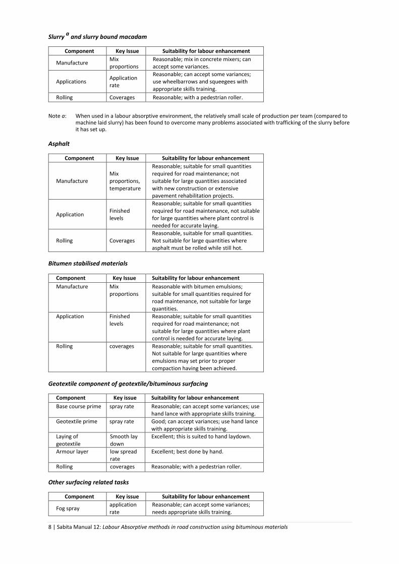
Slurry
a and slurry bound macadam
Component Key Issue Suitability for labour enhancement
Manufacture Mix proportions
Reasonable; mix in concrete mixers; can accept some variances.
Applications Application rate
Reasonable; can accept some variances; use wheelbarrows and squeegees with appropriate skills training.
Rolling Coverages Reasonable; with a pedestrian roller.
Note a: When used in a labour absorptive environment, the relatively small scale of production per team (compared to
machine laid slurry) has been found to overcome many problems associated with trafficking of the slurry before it has set up.
Asphalt
Component Key Issue Suitability for labour enhancement
Manufacture Mix proportions, temperature
Reasonable; suitable for small quantities required for road maintenance; not suitable for large quantities associated with new construction or extensive pavement rehabilitation projects.
Application Finished levels
Reasonable; suitable for small quantities required for road maintenance, not suitable for large quantities where plant control is needed for accurate laying.
Rolling Coverages Reasonable, suitable for small quantities. Not suitable for large quantities where asphalt must be rolled while still hot.
Bitumen stabilised materials
Component Key Issue Suitability for labour enhancement
Manufacture Mix proportions
Reasonable with bitumen emulsions; suitable for small quantities required for road maintenance, not suitable for large quantities.
Application Finished levels
Reasonable; suitable for small quantities required for road maintenance; not suitable for large quantities where plant control is needed for accurate laying.
Rolling coverages Reasonable; suitable for small quantities. Not suitable for large quantities where emulsions may set prior to proper compaction having been achieved.
Geotextile component of geotextile/bituminous surfacing
Component Key issue Suitability for labour enhancement
Base course prime spray rate Reasonable; can accept some variances; use hand lance with appropriate skills training.
Geotextile prime spray rate Good; can accept variances; use hand lance with appropriate skills training.
Laying of geotextile
Smooth lay down
Excellent; this is suited to hand laydown.
Armour layer low spread rate
Excellent; best done by hand.
Rolling coverages Reasonable; with a pedestrian roller.
Other surfacing related tasks
Component Key issue Suitability for labour enhancement
Fog spray application rate
Reasonable; can accept some variances; needs appropriate skills training.

9 | Sabita Manual 12: Labour Absorptive methods in road construction using bituminous materials
Precoating stone coverage Good where quantities are small.
Loading material volume Good where quantities are small.
Maintenance and surfacing repairs
Component Key issue Suitability for labour enhancement
Pothole, patch and surface repairs,
Thoroughness of repair and work zone safety
Good; routinely done by hand.
Edge break repairs
Sound preparation of work area and work zone safety
Good.
Crack sealing
Identification of cracks to be repaired and their preparation and work zone safety
Good; crack sealant should be maintained at the proper temperature and consistency.
Trench reinstatement
Finished levels and proper compaction
Good, but requiring thorough supervision to ensure good compaction throughout.
10 | Sabita Manual 12: Labour Absorptive methods in road construction using bituminous materials
HSSE CONSIDERATIONS
ROAD WORK ZONE SAFETY Traffic control is not covered in detail in this manual. However, it is of paramount importance that
the correct procedures are followed to ensure safety in the work zone for both the construction
workers and the travelling public. As a minimum, the applicable requirements of Chapter 13 of the
South African Road Traffic Signs Manual, Volume 2 Road Traffic Sign Applications, should be
complied with.
TASK SPECIFIC HEALTH AND SAFETY REQUIREMENTS Instead of including a section with general H&S recommendations it was considered more suitable
for this publication to incorporate the key H&S measures in the relevant task method statements
discussed under “Methods” later on. A list of recommended Personal Protective Equipment has
been included below and it is strongly recommended that these PPE items are applied as the
minimum requirements for ALL TASKS performed within the scope of this publication.
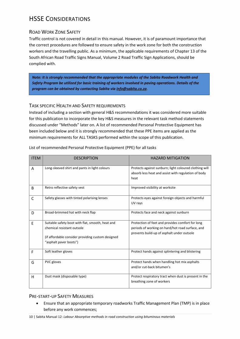
List of recommended Personal Protective Equipment (PPE) for all tasks
ITEM DESCRIPTION HAZARD MITIGATION
A Long-sleeved shirt and pants in light colours Protects against sunburn; light coloured clothing will
absorb less heat and assist with regulation of body
heat
B Retro reflective safety vest Improved visibility at worksite
C Safety glasses with tinted polarising lenses Protects eyes against foreign objects and harmful
UV rays
D Broad-brimmed hat with neck flap Protects face and neck against sunburn
E Suitable safety boot with flat, smooth, heat and
chemical resistant outsole
(if affordable consider providing custom designed
“asphalt paver boots”)
Protection of feet and provides comfort for long
periods of working on hard/hot road surface, and
prevents build-up of asphalt under outsole
F Soft leather gloves Protect hands against splintering and blistering
G PVC gloves Protect hands when handling hot mix asphalts
and/or cut-back bitumen’s
H Dust mask (disposable type) Protect respiratory tract when dust is present in the
breathing zone of workers
PRE-START-UP SAFETY MEASURES Ensure that an appropriate temporary roadworks Traffic Management Plan (TMP) is in place
before any work commences;
Note: It is strongly recommended that the appropriate modules of the Sabita Roadwork Health and
Safety Program be utilized for basic training of workers involved in paving operations. Details of the
program can be obtained by contacting Sabita via [email protected].

11 | Sabita Manual 12: Labour Absorptive methods in road construction using bituminous materials
Ensure all workers are properly briefed and appropriately dressed for prevailing conditions;
Designate a competent team leader to coordinate work zone Health and Safety
communication and controls.
METHODS To ensure that the method statements do not contain too large a volume of information, some were
broken down into various elements. An example is the spray seal operation, which was divided into
the following activities:
• Surface preparations;
• spray operations; and
• stone aggregate application.
In such cases a general method is described in detail and simply referred to in the specific method.
For some operations alternative method statements are given, employing a range of materials and /
or procedures. The selection of the optimum procedure would be based on resources and specific
site conditions. Also, the method statements may not be grouped in a sequence as dictated by the
project requirements; the procedure actually employed may need to be compiled from two or more
of the method statements covered to meet project specifications.
Methods presented in this section are divided into the following categories and numbered
accordingly.
Preparation of base
P 01: Preparing a base course surface
P 02: Protecting kerbs and road furniture
P 03: Watering of base course
General operations
G 01: Spray application of a bituminous binder by hand
G 02: Application of stone aggregate
G 03: Mixing of slurry
G 04: Application of slurry
A: application as a seal coat
B: application as a filler
Construction of bituminous surfacings
S 01: Single seal
S 02: Double seal
S 03: Cape seal
S 04: Graded crushed stone seal
S 05: Asphalt wearing surfacing
S 06: Cold mix asphalt surfacing
S 07: Slurry bound macadam
Maintenance operations
M 01: Pothole repairs with hot or cold mix asphalt
M 02: Pothole Repairs with a fabricated road patch
M 03: Base and surface repairs

12 | Sabita Manual 12: Labour Absorptive methods in road construction using bituminous materials
M 04: Edge break repairs with bitumen stabilised material
M 05: Crack sealing – (less than 5 mm width)
M 06: Crack sealing – (more than 5 mm width)
M 07: Crack sealing – geotextile fabric
M 08: Crack sealing – fabricated road patch
M 09: Trench reinstatement

13 | Sabita Manual 12: Labour Absorptive methods in road construction using bituminous materials
PREPARATION OF BASE
P 01: PREPARING A BASE COURSE SURFACE
Description
Before proceeding with the application of a bituminous surfacing, the substrate, often a granular
base, requires pre-treatment. This operation consists of demarcating the area to be treated and
sweeping to remove all loose material and foreign debris.
Requirements
LABOUR PLANT / EQUIPMENT MATERIAL No. Class No. Type No. Description
As req. General workers (1 sweeper for every 125 m2 of road surface)
2 Hammers As req. Nails
As req. Brooms Bass (1 broom for every 125 m2 of road surface)
As req. As req.
6 mm rope Reinforced paper
1 Measuring tape
Method and procedure
ACTIVITY STEP KEY POINTS 1 Determine the length of
base course surface to be treated (primed).
1A Each worker can effectively sweep 75 m2 in one hour, depending on the conditions.
1B Ensure the area matches the capacity of the spray tanker.
2
Sweep the base course surface with strokes at right angles to the direction of the road, starting at the highest point.
2A Remove all loose and foreign material.
2B
The sweeping should be done firmly, but slowly in order to minimise the raising of dust. (Wear dust masks if dust is present in breathing zone)
3 Demarcation of area to be primed (on roads where kerbs are not provided) Where kerbs are provided, key points 3A, 3B and 3C are not applicable.
3A Hammer 100 mm long nails 90 mm into the base course on both sides of the road indicating the width of surfacing to be placed.
3B These nails should be placed at most 50 m apart on straight sections, and 10 m apart on curves.
3C By stringing between the nails with the rope, the edge of the area should be marked.
3D Place a strip of reinforced paper approximately 300 mm wide at the start and end of the section to be sprayed. The length of the reinforced paper depends on the length of the spray bar.
Quality standard
All loose soil and foreign materials removed, the top surfaces of stones exposed and the area to be
sprayed clearly marked out.
Bituminous binders should only be applied to base layers once they have dried sufficiently, as
specified by the client or its agent.
Photo 1: Properly swept base

14 | Sabita Manual 12: Labour Absorptive methods in road construction using bituminous materials
P 02: PROTECTING KERBS AND OTHER ROADSIDE FURNITURE
Description
Protection of kerbs and other roadside furniture against contamination by bituminous products prior
to their application by spraying
Requirements
LABOUR PLANT / EQUIPMENT MATERIAL No. Class No. Type No. Description
As req. General workers 1 Shovel per general worker
As req. Plastic, sand, clay / mud, paper, splash-boards
Method and procedure
ACTIVITY STEP KEY POINTS 1 Identify objects to be
protected. 1A The effect of wind must be considered.
2 Protect kerbs and other roadside furniture with appropriate material.
2A Where such protection as plastic or paper is used, ensure that it is firmly placed and fully protective.
3 When the spraying of bituminous binder is complete, the protection should be removed.
3A Dispose of all protective materials using an environmentally sound method.
Quality standard
All kerbs and roadside furniture should be unstained with bituminous materials, following their
application.
15 | Sabita Manual 12: Labour Absorptive methods in road construction using bituminous materials
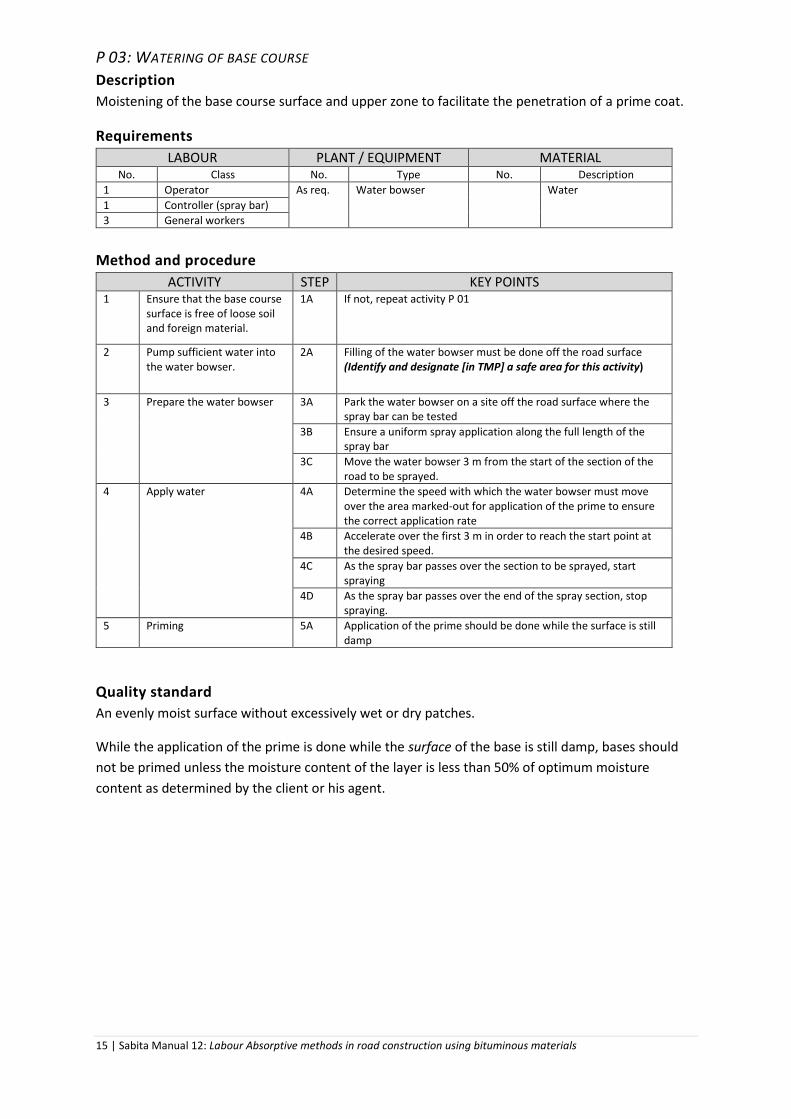
P 03: WATERING OF BASE COURSE
Description
Moistening of the base course surface and upper zone to facilitate the penetration of a prime coat.
Requirements
LABOUR PLANT / EQUIPMENT MATERIAL No. Class No. Type No. Description
1 Operator As req. Water bowser Water
1 Controller (spray bar)
3 General workers
Method and procedure
ACTIVITY STEP KEY POINTS 1 Ensure that the base course
surface is free of loose soil and foreign material.
1A If not, repeat activity P 01
2 Pump sufficient water into the water bowser.
2A Filling of the water bowser must be done off the road surface (Identify and designate [in TMP] a safe area for this activity)
3 Prepare the water bowser 3A Park the water bowser on a site off the road surface where the spray bar can be tested
3B Ensure a uniform spray application along the full length of the spray bar
3C Move the water bowser 3 m from the start of the section of the road to be sprayed.
4 Apply water 4A Determine the speed with which the water bowser must move over the area marked-out for application of the prime to ensure the correct application rate
4B Accelerate over the first 3 m in order to reach the start point at the desired speed.
4C As the spray bar passes over the section to be sprayed, start spraying
4D As the spray bar passes over the end of the spray section, stop spraying.
5 Priming 5A Application of the prime should be done while the surface is still damp
Quality standard
An evenly moist surface without excessively wet or dry patches.
While the application of the prime is done while the surface of the base is still damp, bases should
not be primed unless the moisture content of the layer is less than 50% of optimum moisture
content as determined by the client or his agent.

16 | Sabita Manual 12: Labour Absorptive methods in road construction using bituminous materials
GENERAL OPERATIONS
G 01: SPRAY APPLICATION OF A BITUMINOUS BINDER BY HAND
Description
A spray application of a bituminous binder entails the even, uniform application of the binder to a
prepared base layer as a prime coat, or existing surface, prior the application of stone aggregate, or
a second uniformly even application of a binder on top of a recently applied and prepared layer of
stone aggregate.
Since the use of a spray tanker, equipped with the necessary pumping, metering and spray bar
equipment is recommended practice for extended areas, the operation in this manual applies to
limited areas, such as intersections and parking areas not subjected to heavy traffic. It entails either
a hand operated spray cart with a 200 litres drum holder or the use of a spray tanker towed with a
tractor or bakkie.
The emulsion can be sprayed direct from the 200 litre drums if the hand pulled cart is used. Should a
towed tanker be used, the required number of drums will need to be pumped into the cart at the
correct handling temperature, making allowance for the expansion of the binder in the cart while
heating.
NOTE: In the interests of limiting the exposure of workers to the burns and inhalation of fumes associated
with the application of penetration bitumen and cutback bitumen by hand, is recommended that only
bitumen emulsions be considered for labour intensive methods for spray seal work.
Consequently the description of methods in this manual will be confined to the use of these binders
for surfacing applications. For prime coats the use of both inverted bitumen emulsion and cut back
bitumen is covered.
Requirements
LABOUR PLANT / EQUIPMENT MATERIAL No. Class No. Type No. Description
1 Operator 1 Spray cart or spray tanker As req. Specified bituminous binder
1 or 2
Controller (hand lance)
As req. Spanners to adjust hand lance nozzle
3 General workers As req. Cloth for cleaning As req. Diesel
1 Gas bottle, regulator, hose and burner
For each of controller and general workers
Personal protection equipment
Method and procedure
ACTIVITY STEP KEY POINTS 1 Ensure that the road surface
has been prepared and any kerbs and road side furniture have been prepared and protected
1A See methods P 01 and P 02 and, in the case of the application of a prime coat, method P 03
2 Carry out prestart checks on the gas system
2A Check gas bottle, regulator, hose and burner for leaks.

17 | Sabita Manual 12: Labour Absorptive methods in road construction using bituminous materials
3 Heat the bituminous binder in the batch holding tank to the required temperature
3A Adhere to the supplier’s directions. (See the table Types and grades of bituminous binders below)
3B Ensure the correct minimum road surface temperature is obtained before the bituminous binder is applied.
4 Prepare spray tanker and hand lance
4A Park the spray tanker off the road surface where the hand lance can be tested.
4B Carry out the prestart checks on the pump and motor for leaks and test the hand lance.
4C Ensure the tanker is parked on level terrain; record the level of the bituminous binder within the tanker on a suitable control sheet.
4D Move the spray tanker onto the road surface so that the hand lance is correctly positioned at the start point.
4E Record the temperature reading of the bituminous binder in the tanker. If less that the minimum required, reheat using gas burners.
5 Apply bituminous binder 5A Confirm the required application rate with the client or its agent. To assist the hand lance controller, prepare a 1 m x 1 m square by uniformly hand painting the correct amount of the bituminous binder on the square to provide a visual guide
5B Spray the bituminous binder with a constant spray action, avoiding bare pitches and achieving an even application. It is recommended that spraying is carried out in wide sweeping movements of the hand lance with 1/3 overlaps between successive applications.
5C The general workers should support and move the spray hose as the hand lance controller advances.
5D Avoid skin contact with the bituminous product at all times. (Wear suitable gloves)
5E When spraying larger areas a second hand lance controller is required as relief.
6 Check calibration after
every 300 litres sprayed b
6A Park the tanker on level terrain.
6B Measure the level of bituminous binder remaining in the tanker.
6C
Calculate the actual spray rate based on the volume used and the demarcated area. It the actual spray rate from the required spray rate by more or less than 0.15 litres per square meter, the hand lance controller should be advised. Care should be taken not to overcompensate when making adjustments.
7 Completion 7A Clean spray equipment using diesel. (Wear PVC gloves)
7B When the spraying of bituminous binder is complete, all protective materials should be removed and disposed of in an environmentally sound manner. (Provide a suitable metal container with lid to collect contaminated material for safe disposal)
Note b: When using a spray trolley, the check should be carried out after emptying of a drum, i.e. 200
litres.
Quality standard
Application rates
Spraying by an experienced hand lance controller can achieve rates to within 0.10 l/m2 of the
specified rate. However, occasional larger variations can be expected. Each situation must be
18 | Sabita Manual 12: Labour Absorptive methods in road construction using bituminous materials
carefully evaluated, taking into account traffic usage, locality and type of spray seal being
constructed. In some seals, e.g. a sand seal, the application rate is less critical even with some heavy
traffic.
In areas where prime coats have been over-applied, it can be “blotted” with 7.1 mm stone
aggregate. Crusher dust is not advisable as it tends to stick together and is more difficult to remove
from the road surface.
Plant
All plant and equipment used on the road during construction of the spray seal shall be free of any
binder or fuel leaks. The minimum specifications for a spray tanker are:
It shall be capable of maintaining the binder temperature as specified;
It shall have a facility whereby the contents are circulated regularly.
The piping should be free of leaks and the motor, where present, should have sufficient oil
and fuel and operate correctly, having no leaks, with the pulley sufficiently tight.
If necessary, spray nozzles should be cleaned with diesel, away from the road surface. Care
should be taken not to cause spillages that will damage the environment. The trial spray can
be done back into the drum to avoid pollution
There are two options for spray tankers:
A tractor drawn small tanker (1 000 – 2 000 litres) with its own 5 kW motor / pump and
spray bar. This type of unit can be calibrated to a reasonable degree of accuracy; and
A hand drum trolley with a 2.5 kW motor, hand lance and carrying a 200 litre drum. This
option requires extra training for the hand lance controller to gauge the distribution of the
applied bituminous binder.
Weather limitations
No spraying of bituminous products shall be done during foggy or rainy weather, or when the
temperature of the road surface is below the minimum specified by the client or his agent.
Storage and spraying temperatures of bituminous binders
As bitumen is invariably handled and applied at elevated temperatures, it brings with it a number of
hazards. Hence it is crucially important that sound and responsible practices are observed during
the handling and application the product. These practices are described in detail in Sabita Manual 8:
Guidelines for the safe and responsible handling of bituminous products.
19 | Sabita Manual 12: Labour Absorptive methods in road construction using bituminous materials
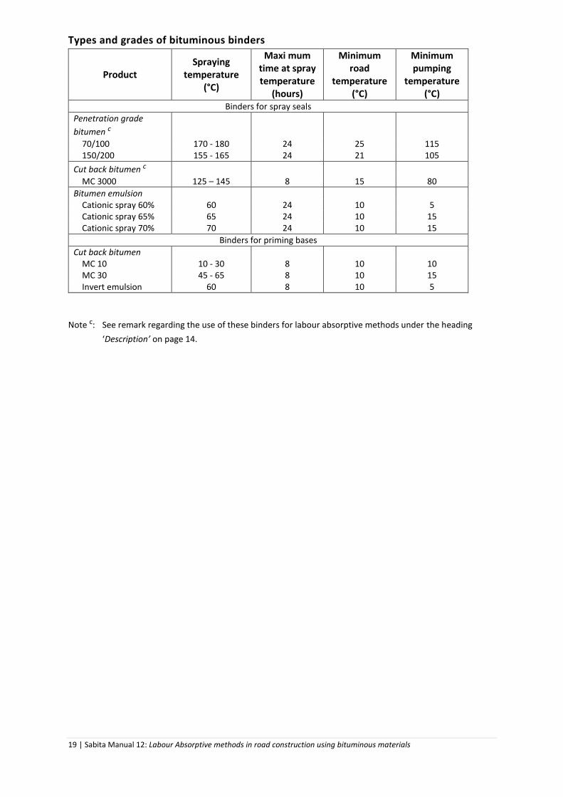
Types and grades of bituminous binders
Product Spraying
temperature (°C)
Maxi mum time at spray temperature
(hours)
Minimum road
temperature (°C)
Minimum pumping
temperature (°C)
Binders for spray seals
Penetration grade
bitumen c
70/100 170 - 180 24 25 115 150/200 155 - 165 24 21 105
Cut back bitumen c
MC 3000 125 – 145 8 15 80
Bitumen emulsion Cationic spray 60% 60 24 10 5 Cationic spray 65% 65 24 10 15 Cationic spray 70% 70 24 10 15
Binders for priming bases
Cut back bitumen MC 10 10 - 30 8 10 10 MC 30 45 - 65 8 10 15 Invert emulsion 60 8 10 5
Note c: See remark regarding the use of these binders for labour absorptive methods under the heading
‘Description’ on page 14.
20 | Sabita Manual 12: Labour Absorptive methods in road construction using bituminous materials
G 02: APPLICATION OF STONE CHIPS
Description
This operation entails the loading, distribution and spreading of stone chips, after the application of
a coat of bituminous binder onto a base course, existing surfacing or a previously applied layer of
stone chips. The first application of stone is followed by another bituminous binder application –
either as a tack coat for a second application of stone chips; alternatively, in the case of a single seal,
as a light application of binder (fog spray) to ensure that stone particles are locked in.
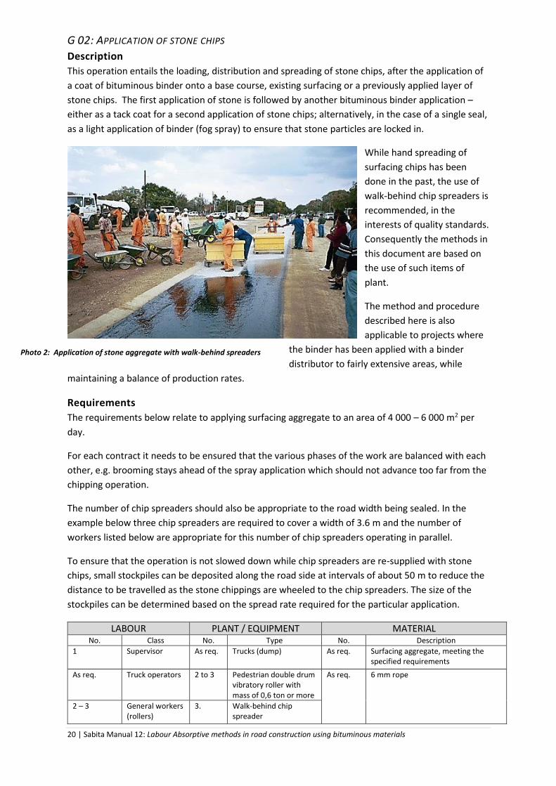
While hand spreading of
surfacing chips has been
done in the past, the use of
walk-behind chip spreaders is
recommended, in the
interests of quality standards.
Consequently the methods in
this document are based on
the use of such items of
plant.
The method and procedure
described here is also
applicable to projects where
the binder has been applied with a binder
distributor to fairly extensive areas, while
maintaining a balance of production rates.
Requirements
The requirements below relate to applying surfacing aggregate to an area of 4 000 – 6 000 m2 per
day.
For each contract it needs to be ensured that the various phases of the work are balanced with each
other, e.g. brooming stays ahead of the spray application which should not advance too far from the
chipping operation.
The number of chip spreaders should also be appropriate to the road width being sealed. In the
example below three chip spreaders are required to cover a width of 3.6 m and the number of
workers listed below are appropriate for this number of chip spreaders operating in parallel.
To ensure that the operation is not slowed down while chip spreaders are re-supplied with stone
chips, small stockpiles can be deposited along the road side at intervals of about 50 m to reduce the
distance to be travelled as the stone chippings are wheeled to the chip spreaders. The size of the
stockpiles can be determined based on the spread rate required for the particular application.
LABOUR PLANT / EQUIPMENT MATERIAL No. Class No. Type No. Description
1 Supervisor As req. Trucks (dump) As req.
Surfacing aggregate, meeting the specified requirements
As req. Truck operators 2 to 3 Pedestrian double drum vibratory roller with mass of 0,6 ton or more
As req. 6 mm rope
2 – 3 General workers (rollers)
3. Walk-behind chip spreader
Photo 2: Application of stone aggregate with walk-behind spreaders

21 | Sabita Manual 12: Labour Absorptive methods in road construction using bituminous materials
6 - 9 General workers (aggregate loading)
20 Wheelbarrows (2 of which are used for back-chipping)
9 – 12 (depending on stockpile distances)
General workers (wheelbarrows)
9 Shovels
12 (4 per chip spreader)
3 General workers and 1 controller per chip spreader
8 – 10 Brooms, bass
4 General workers (back-chipping)
3 – 6 General workers (brooming)
Method and procedure
ACTIVITY STEP KEY POINTS 1 Demarcate the area to be
chipped 1A Ensure that the longitudinal edge and centre line are demarcated
with the 6 mm rope.
2 Apply stone chips to sprayed bituminous binder
2A The stone chips should be clean, free of dust and other deleterious materials and, where specified by the client or his agent, should be precoated with a suitable precoating fluid to promote adhesion of the binder.
2B The stone application must commence as soon as practically possible after the spraying operation to ensure that the chips fall into the unbroken emulsion. (Workers to wear dust masks to protect against inhalation of respirable silica dust)
2C The walk-behind chip spreaders are pushed by three workers plus a controller who should ensure that the chipping operation takes place along the correct line, in relation to the edge or the path of an adjacent chip spreader.
2D In supplying the chip spreaders, the aggregate is carted in wheelbarrows on previously spread stone chips.
3 Rolling of newly applied stone chips
3A Rolling must commence as soon as possible to assist with the bedding down of the stones.
3B No severe turns should be made on the surface itself until the chips are well bedded down.
3C Any turning needs to be gradual on the oldest section of the applied aggregates to prevent them from being dislodged.
4 Back chipping 4A Once the whole demarcated area has been covered, the genera workers assigned to this function inspect the area.
4B In those areas where there are large bare areas between the stone chips, the general worker places additional stones by hand.
4C In those areas where there has been over-chipping the excess stones are removed by brooming.
4D The back-chipping takes place in between roller passes and care should be exercised in this operation so as to avoid collisions; rollers have the right of way.
4E The joints and sides are then lightly broomed to ensure that the stones are in line with the 6 mm rope.
Quality standard
In the case of a single or first application, the finished product is a single layer carpet of stone
aggregate with the individual particles in shoulder to shoulder contact, without open spaces. In the
case of an application of a second or subsequent layer of aggregate, the stone chips should fit evenly
into the spaces of the previous) application. The edges of the carpet should be neatly finished.

22 | Sabita Manual 12: Labour Absorptive methods in road construction using bituminous materials
Aggregates should comply with the requirements of the project specification and should be free of
dust, clay and other deleterious organic matter.
Every effort should be made to apply the stone chips at the correct spread rate; too lean an
application may result in the emulsion being set by the time the back chipping occurs, leading to
poor bonding and eventual ravelling. Over-application of aggregate results in additional work for
the sweepers to remove the excess stone from the surface. This could also result in a shortage of
aggregate before the day’s production is achieved.
In cases where a graded crushed stone aggregate is used, as described in Method S 04, the specified
grading should be met and the aggregate should not contain more than 10% fines. Excessive dust
will result in a poor bond of the crushed stone aggregate with the binder, resulting in subsequent
stone loss. Normally in this type of surfacing a semi-priming elastomeric polymer modified binder is
recommended. The application should be carried out with a binder distributor at a temperature of
between 130 and 135oC to ensure the correct viscosity. A diluted fog spray is recommended on the
graded crushed stone aggregate seals. The total application of the binder should comply with the
project specification.
In cases where sand is used as a second aggregate layer, this material should be spread (either by
hand using shovels or walk behind chip spreaders) onto the second spray of emulsion before it has
broken. When using a shovel to spread the sand, it should be done in such a manner that the sand
falls vertically into the surface in as widespread an arc as is possible. The spread rate should be such
that the binder can bond with the sand and no excess binder is visible. Slight over application is
preferable to under-application. Light drag-brooming of the layer will spread the sand evenly over
the surface. Any excess sand will need to be broomed off once the binder has broken and the
required quantity of sand is bonded to the layer.
23 | Sabita Manual 12: Labour Absorptive methods in road construction using bituminous materials
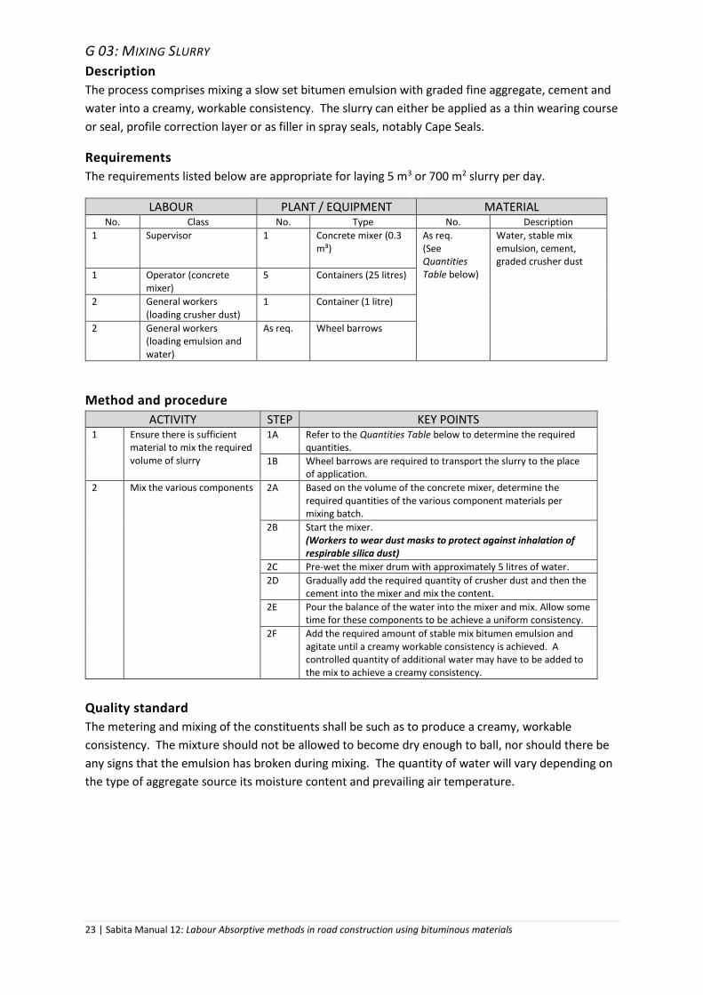
G 03: MIXING SLURRY
Description
The process comprises mixing a slow set bitumen emulsion with graded fine aggregate, cement and
water into a creamy, workable consistency. The slurry can either be applied as a thin wearing course
or seal, profile correction layer or as filler in spray seals, notably Cape Seals.
Requirements
The requirements listed below are appropriate for laying 5 m3 or 700 m2 slurry per day.
LABOUR PLANT / EQUIPMENT MATERIAL No. Class No. Type No. Description
1 Supervisor 1 Concrete mixer (0.3 m³)
As req. (See Quantities Table below)
Water, stable mix emulsion, cement, graded crusher dust
1 Operator (concrete mixer)
5 Containers (25 litres)
2 General workers (loading crusher dust)
1 Container (1 litre)
2 General workers (loading emulsion and water)
As req. Wheel barrows
Method and procedure
ACTIVITY STEP KEY POINTS 1 Ensure there is sufficient
material to mix the required volume of slurry
1A Refer to the Quantities Table below to determine the required quantities.
1B Wheel barrows are required to transport the slurry to the place of application.
2 Mix the various components
2A Based on the volume of the concrete mixer, determine the required quantities of the various component materials per mixing batch.
2B Start the mixer. (Workers to wear dust masks to protect against inhalation of respirable silica dust)
2C Pre-wet the mixer drum with approximately 5 litres of water.
2D Gradually add the required quantity of crusher dust and then the cement into the mixer and mix the content.
2E Pour the balance of the water into the mixer and mix. Allow some time for these components to be achieve a uniform consistency.
2F Add the required amount of stable mix bitumen emulsion and agitate until a creamy workable consistency is achieved. A controlled quantity of additional water may have to be added to the mix to achieve a creamy consistency.
Quality standard
The metering and mixing of the constituents shall be such as to produce a creamy, workable
consistency. The mixture should not be allowed to become dry enough to ball, nor should there be
any signs that the emulsion has broken during mixing. The quantity of water will vary depending on
the type of aggregate source its moisture content and prevailing air temperature.

24 | Sabita Manual 12: Labour Absorptive methods in road construction using bituminous materials
Quantities
Nominal rate of application m3/m2
Materials required Cement
m3/100 m2
Graded aggregate crusher dust m3/100 m2
Water litre/100 m2
Emulsion1 litre/100 m2
0.006 96 128 0.006 0.6
0.008 128 184 0.008 0.8
0.020 320 460 0.020 2.0
It is recommended that, before construction commences, the constituent materials should be mixed
in their predetermined proportions in a small container to determine their compatibility. The
resultant mix should be shaped into a patty and allowed to dry in the sun for a visual inspection.
The following tests should be carried out on site during the execution of the works:
• Daily: Bulking test on the crusher dust to determine whether the mix proportions require
adjustment.
• When the water source is changed, dilute the emulsion 50:50 with the water in a glass
container to check whether the fluids are compatible.
1 Anionic 60% stable mix bitumen emulsion

25 | Sabita Manual 12: Labour Absorptive methods in road construction using bituminous materials
G 04A: APPLICATION OF SLURRY AS A SEAL COAT
Description
The preparation of the road surface and the discharging, spreading and finishing of the slurry of
thickness 6 – 15 mm.
Requirements
Below is the typical composition of a slurry team necessary to mix and lay 5m3 or 700m² per day.
LABOUR PLANT / EQUIPMENT MATERIAL No. Class No. Type No. Description
1 Supervisor 3 Wheel barrows
As req. Water
3 General workers (pushing wheelbarrows)
5 Shovels As req. 6 mm rope
3 General workers (spreading with squeegees)
5 Squeegees (450 mm wide; (plain or serrated)
As req. Diesel
1 General workers (sweeping)
As req. Brooms (bass)
As req. Hessian sheet
As req. Watering can
As req. Gumboots
Method and procedure
ACTIVITY STEP KEY POINTS
1 Prepare road surface 1A Slurry should be applied during the day, only in fair weather conditions. Repairs to potholes and cracks should have been done prior to resealing with slurry. (See relevant methods under Maintenance operations.)
1B Determine the size of the area that can be covered within a day.
1C The surface should be swept clean and free of foreign material. If necessary apply Method P 01 to prepare the surface. (Workers to wear dust masks when sweeping)
1D Lightly sprinkle the allotted area with water. There should be no free standing water on the surface.
1E Using the rope demarcate the area into lanes that can be covered by the discharging operation.
2 Discharge and spread the slurry
2A With the wheel barrows completely discharge the slurry over the central portion of the demarcated area. Ensure there is not breaking of the emulsion or formation of lumps during applications. If this occurs the mix must be discarded. Remix the slurry on the road surface and spread with squeegees to obtain a uniform consistency.
2B Spread the slurry over the full width of the lane with the rubber squeegees. Use serrated squeegees when spreading the first of multiple layers.
2C Continue spreading until an even layer, both in terms of thickness and finish, is obtained.
2D When the first lane is complete, continue with the second lane following the same procedure. There should be no overlapping at any longitudinal joint or uncovered areas. The overlap on transverse joints should be between 25 mm and 150 mm.

26 | Sabita Manual 12: Labour Absorptive methods in road construction using bituminous materials
2E All stone dislodged during the application process should be removed.
3 Apply second slurry layer if
required by the client or his
agent
3A Generally two layers will be required if the slurry is applied as a surfacing.
3B The second layer must only be applied after the first layer has dried and been opened to traffic, for a period specified by the client or his agent.
3C Before applying the second layer, the surface must be clean of dust, dirt and foreign materials.
4 Finish the upper surface 4A Use a wet hessian sheet to drag the surface and give the final “drag finish”. Slurry takes approximately four hours to set and dry properly under favourable weather conditions and no traffic should be allowed onto the freshly laid slurry before it has dried sufficiently. A useful means of assessing this is to check whether the slurry can withstand the turning force of a shoe heel under a person’s weight without scuffing.
5 Clean all tools and equipment
5A Thoroughly clean all tools and equipment after each day’s work, using diesel. (Workers must protect hands by wearing PVC gloves)
Quality standard
The road surface is finished to specified widths, lines, thickness and uniform texture. All spillages and
excess quantities of slurry should be removed from the road surface.
Photo 3: Application of slurry with squeegees
Nominal rates of application of slurry seal
Nominal thickness of slurry layer Nominal rate of application m3/m2
6 mm 0.008
15 mm 0.020

27 | Sabita Manual 12: Labour Absorptive methods in road construction using bituminous materials
G 04B: APPLICATION OF SLURRY AS A FILLER2
Description
The preparation of the surfacing and the discharging, spreading and working of the slurry into the
spaces between the surfacing aggregate, typically in Cape seals.
Requirements
LABOUR PLANT / EQUIPMENT MATERIAL No. Class No. Type No. Description
1 Supervisor 3 Wheel barrows
As req. Water
3 General workers (pushing wheelbarrows)
5 Shovels As req. 6 mm rope
4 General workers (spreading with squeegees)
10 - 15 Squeegees 450 mm wide; (plain only)
As req. Diesel
1 General workers (sweeping)
As req.
Brooms (bass)
As req.
Hessian sheet
As req.
Watering can
As req.
Gumboots
Method and procedure
ACTIVITY STEP KEY POINTS 1 Prepare road surface
1A Slurry should be applied during the day, only in fair weather conditions. The slurry can only be applied once the second spray application on the aggregate has fully dried, which may take a few days.
1B Determine the size of the area that can be covered within a day.
1C Sweep all foreign material from the road surface where necessary. (Workers to wear dust masks when sweeping)
1D Lightly sprinkle the allotted area with water. There should be no free standing water on the surface.
1E Demarcate the area into lanes that can be covered by the discharging action with the rope.
2 Discharge and spread the slurry
2A With the wheel barrows completely discharge the slurry over the central portion of the demarcated area. Ensure there is no breaking of the emulsion or formation of lumps during applications. If this occurs the mix must be discarded. Remix the slurry on the road surface and spread with squeegees to obtain a uniform consistency.
2B Spread the slurry over the full width of the lane with the rubber squeegees. The team that does the spreading by squeegee should be divided into four sections. The first section pushes the slurry in one direction, while the second section pushes the mix back down in the opposite direction. The third and fourth sections do the same but across the road. This is to ensure that the slurry is forced into all the spaces between the stone chippings and does not leave any voids. This will ensure that the aggregate is well bedded
2 The application of slurry as a filler in macadam is covered in method S 07: Slurry bound macadam.

28 | Sabita Manual 12: Labour Absorptive methods in road construction using bituminous materials
down with slurry fully surrounding each stone to ensure good retention and a waterproof layer.
2C Continue spreading until the tops of the surfacing aggregates are just visible.
2D When the first lane is complete, continue with the second lane following the same procedure. There should be no overlapping at any longitudinal joint or uncovered areas. The overlap on transverse joints should be between 25 mm and 150 mm.
2E All stone dislodged during the application process should be removed.
3 Apply second slurry layer if
required by the client or his
agent
3A Generally two layers will be required if the surfacing is a 20 mm Cape seal. For 14 mm Cape seals, a single application of slurry is normally sufficient.
3B The second layer must only be applied after the first layer has dried and been opened to traffic, for a period specified by the client or his agent.
3C Before applying the second layer, the surface must be clean of dust, dirt and foreign materials.
4 Finish the upper surface 4A Use a wet hessian sheet to drag the surface and give the final “drag finish”. Slurry takes approximately four hours to set and dry properly under favourable weather conditions and no traffic should be allowed onto the freshly laid slurry before it has dried sufficiently.
5 Clean all tools and equipment 5A Thoroughly clean all tools and equipment after each day’s work, using diesel.
Quality standard
The road surface is finished to specified widths, lines, thickness and a dense and uniform texture. All
spillages and excess quantities of slurry should be removed from the road surface.
Photo 4: Applying slurry as a seal filler
29 | Sabita Manual 12: Labour Absorptive methods in road construction using bituminous materials
Nominal rates of application of slurry seal
Nominal size of aggregate used in the spray seal Nominal rate of application m3/m2
14 mm 0.006
20 mm 0.008
CONSTRUCTION OF BITUMINOUS SURFACINGS
S 01: CONSTRUCTION OF A SINGLE SEAL
Description
A sprayed application of bituminous binder followed by a single layer of stone chips. These stone
chips are sometimes covered by a second application of binder or fog spray to ensure that they are
all “locked in” and form an integral part of the seal.
Requirements
LABOUR PLANT / EQUIPMENT MATERIAL No. Class No. Type No. Description
As per Methods G 01 and G 02
As per Methods G 01 & G 02
As req. Aggregates and binder as per Methods G 01 & G 02
Method and procedure
ACTIVITY STEP KEY POINTS 1 Ensure that the road surface
has been prepared and any kerbs and road side furniture have been prepared and protected
1A See Methods P 01 & P 02
2 Apply the binder to the primed base surface
2A Refer to Method G 01
2B Sprayed bitumen should only be applied in good weather conditions. Windy conditions should be avoided
3 Apply stone chips 3A Refer to Method G 02
4 Apply a second coat of binder (fog spray)
4A Refer to Method G 01 A fog spray of diluted emulsion should preferably take place after 2 – 3 weeks once aggregates have bedded down and excess stones have been swept to the side of the road, either by traffic or brooming.
Quality standard
The road surface is finished to specified widths, lines, application rates with a uniform, well-knit
texture. Stone chips are embedded in a film of bituminous binder and locked in, with minimum
dislodgement during early traffic.
As errors in the application rate of the bituminous binders cannot be readily rectified, as is the case
with double seals, controls on site must be closely monitored to ensure an acceptable, serviceable
and durable riding surface.

30 | Sabita Manual 12: Labour Absorptive methods in road construction using bituminous materials
S 02: CONSTRUCTION OF A DOUBLE SEAL
Description
A sprayed application of bituminous binder followed by a single layer of stone chips, followed by
a second spray application of bituminous binder and a single layer of smaller sized stone chips or
sand. The final layer of stone chips is sometimes covered by a fog spray to prevent whip-off. Double
seals can be made up from the following combinations of stone aggregate and sand:
• 10 mm stone chips and sand
• 14 mm stone chips and sand
• 14 mm stone chips and 7.1 mm chips
Requirements
LABOUR PLANT / EQUIPMENT MATERIAL No. Class No. Type No. Description
As per Methods G 01 and G 02
As per Methods G 01 & G 02
As req. Aggregates and binder as per Methods G 01 & G 02
Method and procedure
ACTIVITY STEP KEY POINTS 1 Ensure that the road
surface has been prepared and any kerbs and road side furniture have been prepared and protected
1 See Methods P 01 & P 02.
2 Apply the binder to the primed base surface
2A Refer to Method G 01.
2B Sprayed bitumen should only be applied in good weather conditions. Windy conditions should be avoided.
3 Apply first layer of stone chips
3A Refer to Method G 02.
4 Apply a second coat of binder
4A Refer to Method G 01.
4B This second application of binder should not take place before the binder in the first spray application is completely cured, or, in the case of bitumen emulsions, completely broken.
4C Corrections need to be made to the spray rate should insufficient or surplus binder have been applied during the first spray operation. The client or his agent should advise accordingly.
5 Apply the second layer of aggregate chippings or sand
5A Refer to Method G 02.
6 Fog spray (if required)
6A Refer to Method G 01.
6B The fog spray of diluted emulsion should preferably take place 2 – 3 weeks after the application of the final layer of aggregate, once the stones have bedded down and excess stones have been swept to the side of the road, either by traffic or brooming.
Note: The construction of this seal type - especially where two layers of stone chips are used -
should only be considered where there is confidence that the competence and experience the
labourers and supervisors are adequate to carry out the work

31 | Sabita Manual 12: Labour Absorptive methods in road construction using bituminous materials
Quality standard
The road surface is finished to specified widths, lines, thickness application rates with a uniform,
well-knit texture. Stone chips or sand grains are embedded in a film of bituminous binder and
locked in, with minimum dislodgement during early traffic.
While every effort should be made to ensure that binder application rates are according to the
specifications, there is an opportunity to compensate for errors in the application of the first coat of
bituminous binders.
Controls on site must be closely monitored to ensure an acceptable, serviceable and durable riding
surface.
Photo 5: Double seal

32 | Sabita Manual 12: Labour Absorptive methods in road construction using bituminous materials
S 03: CONSTRUCTION OF A CAPE SEAL
Description
A sprayed application of bituminous binder followed by a single layer of stone chips, followed by
one or two applications of slurry to fill the interstices between the stone chips.
The stones used are either 20 mm or 14 mm, with two or one application of slurry, respectively.
Requirements
LABOUR PLANT / EQUIPMENT MATERIAL No. Class No. Type No. Description
As per Methods G 01 & G 02
As per Methods G 01 & G 02
As req. Aggregates and binder as per Methods G 01 & G 02
As per Methods G 03 and G 04B
As per Methods G 03 & G 04B
As req. Aggregates and binder as per Methods G 03 & G 04B
Method and procedure
ACTIVITY STEP KEY POINTS 1 Ensure that the road surface
has been prepared and any kerbs and road side furniture have been prepared and protected
1 See Methods P 01 & P 02.
2 Apply the binder to the primed base surface
2A Refer to Method G 01.
2B Sprayed bitumen should only be applied in good weather conditions. Windy conditions should be avoided.
3 Apply first layer of stone chips
3A Refer to Method G 02.
4 Apply a second coat of binder
4A Refer to Method G 01.
4B Corrections need to be made to the spray rate should insufficient or surplus binder have been applied during the first spray operation. The client or his agent to advise accordingly.
5 Mix and apply the slurry 5A Refer to Methods G 03 & G 04B.
5B When using 20 mm surfacing aggregate the first layer of slurry will leave excess voids on the surface once it has set. A second application will assist in filling these voids, sealing off the layer fully and securing the stone chips on all sides with slurry.
Quality standard
The road surface is finished to specified widths, lines, thickness and application rates with a uniform,
well-knit texture.

33 | Sabita Manual 12: Labour Absorptive methods in road construction using bituminous materials
S 04: CONSTRUCTION OF A GRADED CRUSHED STONE SEAL
Description
A graded crushed stone seal is a sprayed application of modified bituminous binder followed by a
layer of graded crushed stone aggregate. The layer of graded crushed stones is sometimes covered
by a second spray application or fog spray to ensure that all particles are “locked in” and form an
integral part of the seal.
Requirements
LABOUR PLANT / EQUIPMENT MATERIAL No. Class No. Type No. Description
As per Methods G 01 and G 02
As per Methods G 01 & G 02
As req. Semi-priming elastomeric polymer modified binder as specified by the client or his agent.
As req. Graded aggregates as per Method G 02
Method and procedure
ACTIVITY STEP KEY POINTS 1 Ensure that the road surface
has been prepared and any kerbs and road side furniture have been prepared and protected
1A See Methods P 01, P 02 & P 03
1B Due the self-priming properties of the modified binder used for this type of surfacing, base courses are normally not primed.
2 Apply the binder to the base surface
2A Refer to Method G 01.
2B Binder application rates should be adjusted to compensate for some penetration of the binder into the base.
2C Sprayed bitumen should only be applied in good weather conditions. Windy conditions should be avoided.
3 Apply first layer of stone aggregates
3A The self-priming modified binder needs to be left for a period of 20 minutes before application of the stone to ensure that it has penetrated the base sufficiently to act as a bond between the granular layer and the graded crushed stone aggregate seal.
3B Refer to Method G 02.
4 Apply a second coat of binder (fog spray) if specified by the client or his agent
4A Refer to Method G 01.
4B A fog spray of diluted emulsion can be applied once all the graded crushed stone aggregate has been bedded down well and all excess stone aggregate has been swept to the side of the road either by vehicular traffic or brooming – usually 2 – 3 weeks after completion of the layer works. The application rate should not exceed 0.15 l/m2 of net bitumen.
Quality standard
The road surface is finished to specified widths, lines, thickness and application rates with a well-knit
uniform texture.
Spray application rate of the binder must not exceed 1.8 l/m2.
Chippings should not contain more than 10% fines. Excessive dust in the graded crushed stone
aggregate will result in a poor bond of the crushed stone aggregate to the binder, resulting in chip
loss.

34 | Sabita Manual 12: Labour Absorptive methods in road construction using bituminous materials
S 05: CONSTRUCTION OF AN ASPHALT SURFACING
Description
A range of mixtures of aggregate, bituminous binder and mineral filler, produced at an elevated
temperature in an asphalt plant.
While normally placed by mechanical pavers, asphalt, purchased from an established supplier, is
reasonably suitable for placing by hand in limited areas such as driveways, smaller parking areas and
sidewalks.
Requirements
LABOUR PLANT / EQUIPMENT MATERIAL No. Class No. Type No. Description
Preparation of base as per Method P 01 & P 03 Application of prime and tack coat - as per Methods G 01
Prime: As per Methods P 01, P 02 & G 01
As req. Prime as per the table Types and grades of bituminous binders in Method G 01 as specified
Tack coat: As per Method G 01
As req. Tack coat consisting of a 50/50 blend of 60% anionic or cationic emulsion and potable water.
As req. Asphalt supplied by a reputable asphalt manufacturer. For layer thicknesses of less than 30 mm a maximum nominal aggregate size of 7.1 mm is recommended. For thicker layers a maximum nominal aggregate size of 10 mm can be considered.
1 Supervisor 4 Brooms (bass)
As req. Operator (rollers) 6 Shovels
2 General workers (brooming)
3 Wheelbarrows
3 General workers (Wheelbarrow loading)
3 Rakes
3 General workers (wheel barrow pushing)
1 Static steel wheel roller - 2 tons mass (break down rolling)
2 General workers (raking)
1 Pedestrian vibrating roller or small sidewalk roller
2 General workers (hand stamping)
2 Hand stampers
1 Steel probe temperature dial gauge with a measuring range of 0 to 240°C
As req. Tarpaulins for covering asphalt stockpiles
1 3 metre straight edge
Method and procedure
ACTIVITY STEP KEY POINTS 1 Ensure that the
substrate surface has been prepared and primed
1 See Methods P 01, P 03 & G 01.
Apply the tack coat
1B It is normal sound practice to apply a tack coat before placing the asphalt. The application rate will be specified by the client or his agent.

35 | Sabita Manual 12: Labour Absorptive methods in road construction using bituminous materials
2 Setting up level controls
2A The area to be paved needs to be surveyed to ensure that the correct slopes and cross fall are obtained for drainage of surface water. This is especially critical on large areas such as parking areas.
2B C-channels or similar rigid forms need to be laid out to the correct levels and slopes to assist the rakemen to obtain the correct final levels.
2C Normally the work would be carried out in long strips, starting from the lowest point and working towards the highest point.
3 Determining the quantities to be ordered
3A The volume of asphalt required is based on dip readings of asphalt depth over the area to be paved.
3B The quantity (tons) of asphalt to be ordered for the job can be determined using the table Asphalt Coverage below.
4 Accepting delivery to site
4A Before receiving the load the temperature of the mix should be measured to ensure that it is at least 130oC; if not, the load should be rejected.
4B The dumped asphalt should be covered with tarpaulins at all times except when removing material.
4C Delivery of material to site should be coordinated to be reasonably staggered in relation to a day’s production needs There should be no surplus left at the end of a day’s work.
4D Weather conditions should be closely monitored. If rain is imminent, orders should be cancelled in time to stop dispatch from the supplier’s plant.
5 Placing the asphalt 5A The asphalt is loaded into the wheelbarrows from all around the stockpile to ensure that material is continuously removed from hot sections. This will also prevent one side form cooling down and creating a cold crust on the surface that will be unusable and going to waste. (Workers handling hot asphalt must wear suitable clothing, safety footwear and gloves to protect against burns)
5B The asphalt is tipped out as indicated by the workers operating the rakes - in a splayed manner to ease the spreading of the mix to the correct level quickly and effectively. Minimal movement of the material should be required during raking as this will limit the degree of segregation of the material and allow the mix to be compacted as soon as possible before excessive cooling. It is critically important that the level of the raked material should be proud of the finished level. (See table on asphalt coverage)
5C The supervisor should monitor the temperature of the asphalt stockpile. Material that has cooled below 100°C cannot be compacted adequately and such material should be discarded.
6 Compaction 6A Compaction should follow as soon as possible after spreading to the correct level. Where the surface has a cross-fall or camber, placing and compaction should commence at the lower side, working towards the crown or higher edge. Firstly a static roller is used to bed down the material; this is known as “break-down” rolling. The first pass should be made with the driven wheel leading in the direction of travel to ensure that the asphalt is tucked under the wheel and not pushed forward in a wave. This pass will also allow the rakemen to ensure that the correct amount of material has been spread relative to the level controls and that there are no low or high spots. Following the first pass, compaction is continued in half width overlaps until the mat is at the required density and stable. Further (intermediate) compaction is carried out with the vibratory pedestrian roller or side walk roller. A final pass in static mode is made to ensure a smooth finish without any visible roller tracks.
6B No turns should be made on the warm mat while still being compacted. Lateral changes in the position of passes should be carried out on compacted, cooled asphalt. Compaction passes should take place in straight lines working from lower areas to higher ones to allow for a compacted edge to support the next pass.

36 | Sabita Manual 12: Labour Absorptive methods in road construction using bituminous materials
6C Only sufficient water to moisten the roller drums to prevent the mix from sticking to them should be used. Excessive water will accelerate the cooling of the mix which may give rise to inadequate compaction.
6D A 3 m straight edge should be used to ensure that the final level of the finished mat is correct and that the water will drain from the surface as intended. If depressions have formed, all the material in the depressed area will need to be removed, replaced and compacted to prevent a “biscuit layer” being formed.
7 Edge treatment 7A Stampers should be used to ensure that the edges are well compacted and sealed off from any possible water ingress. Care should be taken not to damage any of the edging during this process.
Note: the terms “rake, raking” refers to the use of the flat back end of the rake (lute) to
distribute and spread the material since using the pronged side would tend to segregate the
asphalt.
Asphalt coverage
Compacted thickness (mm)
Pre-compacted thickness (mm)
Coverage (m2/ton)
20 25 20
25 30 - 35 16
30 35 - 40 14
35 40 - 50 12
40 50 - 55 10
Quality standard
A uniformly dense, well-knit, impermeable and even surface, without signs of segregation, dips,
humps or roller marks.
Some precautions that need to be taken to ensure a quality final product include:
• As the material cools very rapidly once spread, no time must be lost in placing and spreading
the asphalt to the correct level and commencement of compaction;
• Excessive quantities of paraffin on the rakes and shovels should be avoided as it will soften
the asphalt and cause it to ravel at an early age; and
• Levels must be carefully controlled to ensure an even, drained surface with no ponding.
Photo 6: Hot asphalt covered with tarpaulins

37 | Sabita Manual 12: Labour Absorptive methods in road construction using bituminous materials
S 06: CONSTRUCTION OF A COLD MIX ASPHALT SURFACING
Description
A mixture of aggregate, cutback bitumen and mineral filler delivered in bags or material mixed with
bitumen emulsions carrying Agrèment SA certification, for application at ambient temperatures in
limited areas of sidewalks, drive ways and repairs to roads carrying light traffic.
Requirements
LABOUR PLANT / EQUIPMENT MATERIAL No. Class No. Type No. Description
Preparation of base as per Method P 01 & P 03
Prime: As per Methods P 01 P 03 & G 01
As req. Prime as per the table Types and grades of bituminous binders in Method G 01
Application of prime - as per Method G 01
Tack coat: As per Method G 01
As req. Tack coat, if specified, consisting of a 50/50 blend of 60% anionic or cationic emulsion and potable water.
Application of tack coat - as per Method G 01
4 Brooms (bass) As req. Bagged cold mix asphalt using either cutback bitumen or bitumen emulsion, supplied by a reputable manufacturer. Fine graded mixes (7.1 mm nominal maximum aggregate size) are the norm to allow for ease of application by hand.
1 Supervisor 6 Shovels As req.
As req. Operator (roller) 3 Wheelbarrows
2 General workers (brooming)
3 Rakes
3 General workers (wheelbarrow loading)
1 Static steel wheel roller - 2 tons mass (break down rolling)
3 General workers (wheel barrow pushing)
1 Pedestrian vibrating roller or small sidewalk roller
1 Hand stampers
2 General workers (raking)
1 3 metre straight edge
2 General workers (hand stamping)
Method and procedure
ACTIVITY STEP KEY POINTS 1 Ensure that the substrate
surface has been prepared and primed
1 See Methods P 01, P 03 & G 01.
Apply the tack coat 1B It is normal sound practice to apply a tack coat before placing the asphalt. The application rate will be specified by the client or his agent.
2 Setting up level controls 2A The area to be paved needs to be surveyed to ensure that the correct slopes and cross fall are obtained for drainage of surface water. This is especially critical on large areas such as parking areas
2B C-channels or similar rigid forms need to be laid out to the correct levels and slopes to assist the rakemen to obtain the correct final levels.
2C Normally the work would be carried out in long strips, starting from the lowest point and working towards the highest point.
3 Determining the quantities to be ordered
3A The volume of asphalt required is based on dip readings of asphalt depth over the area to be paved.
3B The quantity (tons) of asphalt the asphalt to be ordered for the job can be determined using the table Asphalt Coverage given in Method S 05.

38 | Sabita Manual 12: Labour Absorptive methods in road construction using bituminous materials
4 Accepting delivery to site 4A The asphalt can either be delivered to site or collected from the supplier. Although the product may have a limited shelf life, it is better practice to purchase and use as needed.
5 Placing the asphalt 5A The bags should be spread out on the area required to match the required application rate. Leaving the bags in the sun for a short while assist in improving the workability of the cutback based asphalt.
5B The bags should be opened as close to their place of use as is possible to assist the rakemen in spreading the mix to the correct level quickly and effectively. Minimal movement of the cold mix asphalt by the rakemen will assist in a higher productivity rate and less risk of mix segregation. Allowance should be made for 20% reduction in height due to consolidation of the material during compaction.
6 Compaction 6A Compaction should follow as soon as possible after spreading to the correct level. Where the surface has a cross-fall or camber, placing and compaction should commence at the lower side, working towards the crown or higher edge. Firstly a static roller is used to bed down the material; this is known as “break-down” rolling. The first pass should be made with the driven wheel leading in the direction of travel to ensure that the asphalt is tucked under the wheel and not pushed forward in a wave. This pass will also allow the rakemen to ensure that the correct amount of material has been spread relative to the level controls and that there are no low or high spots. Following the first pass, compaction is continued in half width overlaps until the mat is at the required density and stable. Further (intermediate) compaction is carried out with the vibratory pedestrian roller or side-walk roller. A final pass in static mode is made to ensure a smooth finish without any visible roller tracks
6B No turns should be made on the mat while still being compacted. Lateral changes in the position of passes should be carried out on compacted asphalt. Compaction passes should take place in straight lines working from lower areas to higher ones to allow for a compacted edge to support the next pass.
6C Only sufficient water to moisten the roller drums to prevent the mix from sticking should be used. Excessive water will accelerate the cooling of the mix which may give rise to inadequate compaction.
6D A 3 m straight edge should be used to ensure that the final level of the finished mat is correct and that the water will drain from the surface as intended. If depressions have been formed after final compaction, all the material in the depressed area would need to be removed, replaced and compacted to prevent a “biscuit layer” being created.
7 Edge treatment 7A Stampers should be used to ensure that the edges are well compacted and sealed off from any possible water ingress. Care should be taken not to damage any of the edging during this process.
Quality standard
A uniformly dense, impermeable, well-knit and even surface, without signs of segregation, dips,
humps or roller marks.
Some precautions that need to be taken to ensure a quality final product include:
• Allowing sufficient time for the cutter to evaporate is critical in ensuring that the layer
performs as expected once exposed to traffic action.
• The level control must be carefully controlled to ensure an even a surface.

39 | Sabita Manual 12: Labour Absorptive methods in road construction using bituminous materials
• The edges need to be well compacted to ensure no moisture seeps in leading to premature
failure.
• Kerbed edges giving lateral support to the edge of the cold mix asphalt layer tend to prolong
its life by preventing edge breaks from occurring.
Photo 7: Hand-spreading of asphalt between channels

40 | Sabita Manual 12: Labour Absorptive methods in road construction using bituminous materials
S 07: SLURRY BOUND MACADAM
Description
Single-sized aggregate of nominal size ranging from 14 mm to 50 mm with the voids between these stones filled with slurry. Slurry-bound macadam can be used in a wide range of applications such as walkways, driveways, parking areas, roads/streets.
This method is particularly suited for inaccessible / mountainous terrain where large construction equipment is difficult and costly to operate.
Note: The application of this type of surfacing requires the employment of an experienced supervisor and trained work force to ensure a quality product and to avoid work procedures that will compromise the performance and durability of the product.
Requirements
LABOUR PLANT / EQUIPMENT MATERIAL No. Class No. Type No. Description
1 Supervisor As req. Guide rails, gravel edge supports or straight edges and securing equipment to contain the material to the correct line an level
As req. Slurry aggregate, complying with the project specification.
Slurry mixing: as per Method G 03
1 Slurry mixing: as per Method G 03.
As req. based on 250 l/m3 of slurry
Anionic 60% stable mix emulsion.
Slurry application: as per Method G 04B (the number of squeegee spreaders can be reduce to 3)
Slurry application: as per Method G 04B (the number of squeegees s can be reduce to 4
As req. Diesel
1 Compactor operator 3 Pedestrian vibrating roller or plate compactor
As req. based on 1% by mass of slurry aggregate
Ordinary cement.
4 General workers (wheel barrow pushing)
4 Shovels As req. Potable water
3 General workers (wheelbarrow loading – aggregates)
4 Ballast forks
4 General workers (aggregate spreading)
4 Wheelbarrows
1 General workers (raking) 2 Rakes
4 General workers (finishing) 2 Brooms (bass)
2 Hessian cloth (3 m x 2 m)
1 3 metre straight edge
Method and procedure
ACTIVITY STEP KEY POINTS
1 Prepare the base and erect 1A The base is prepared as per Method P 01.
2 Erect and secure containment utensils
2A Guide rails, gravel edge supports or straightedges need to be erected and secured to the correct line and level. The setup needs to be sufficiently firm and robust to withstand the lateral forces acting on them.

41 | Sabita Manual 12: Labour Absorptive methods in road construction using bituminous materials
Allowance should be made for 30 % extra height to accommodate densification of the material during compaction.
3 Placing and compaction of aggregate
3A The aggregate should be tipped out of the wheel barrows as close as possible to where it is required. Every effort should be made to ensure that as little of the underlying layer is disturbed when tipping the materials using the pivot point at the front of the wheel barrow. The aggregate is then spread to the levels given using the ballast forks and rakes. The levels should be checked for evenness and correctness with the 3 m straight edge.
3B Compaction of the aggregate is should commence from the outer edge and moving inwards. Levels should be rechecked for accuracy with the 3 m straight edge. Where necessary material should be added or removed to ensure an even, correct final level. Care should be taken not to disturb the material as it is still quite unstable until the slurry has been applied and it has set.
4 Mixing of slurry 4A The mixing of the slurry is carried out according to Method G 03 according to the mix proportions specified by the client or his agent.
4B The emulsion should be at ambient temperature. To improve workability of the slurry, more water may be added in a controlled manner to achieve a creamy consistency. The quantity of water in the mix will vary depending on the type of aggregate source and prevailing air temperature.
5 Application of slurry 5A The slurry is discharged from the wheelbarrows onto the aggregate. Every effort should be made to ensure that as little of the underlying aggregate layer is disturbed when tipping the materials using the pivot point at the front of the wheel barrow. The slurry is then worked into the voids with the aid of the squeegees, working in all directions to ensure the voids are filled as completely as possible.
5B Ensure there is no breaking of the emulsion or formation of lumps during applications. If this occurs the mix must be discarded.
5C Use should also me made of the vibratory roller to promote penetration of the slurry into the layer. This working in of the slurry should continue until no further penetration into the layer can be achieved.
5D Remove all excess slurry and plate vibrator imprints using a shovel once the slurry has broken
6 Finishing 6A The newly applied slurry should be finished off by dragging a wet hessian sheet over the surface to achieve a uniformly textured surface.
7 Clean all tools and equipment
7A Thoroughly clean all tools and equipment after each day’s work, using diesel.
Quality standard
A uniformly dense, impermeable and even surface, without signs of segregation, dips, humps or
roller marks.
Some precautions that need to be taken to ensure a quality final product include:
In general, careful attention should be paid to the correct methods and procedures to
ensure that the layer will give adequate service.
Ensure that the aggregate consistently complies with to the project specifications.

42 | Sabita Manual 12: Labour Absorptive methods in road construction using bituminous materials
At all times work should only commence if no rain is forecast. Care should also be taken if it
is likely to rain the following day given the depth to which the slurry penetrates and the time
taken to set, especially for thicker layers.
• It is recommended that the following tests should be conducted on site during the execution
of the works:
Bulking of the crusher dust should be carried out daily to establish whether the batch
volume needs to be adjusted
If the water source is changed, dilute it 50:50 with the emulsion in a glass container to
check if it is compatible

43 | Sabita Manual 12: Labour Absorptive methods in road construction using bituminous materials
MAINTENANCE OPERATIONS While the methods described below refer to specific actions to repair obviously distressed areas, it is
always advisable to identify the cause(s) of the particular distress and to examine adjacent areas for
early signs of the same distress types. If present, it is advisable to take steps either to prevent the
further development of such distress or to deal with such areas in the same way as the obvious case.
In many instances damage to road pavements is caused by inadequate draining of surface or sub-
surface water. Whenever repairs are made, the client or his agent should investigate this cause and,
where appropriate take action such as deepening or clearing of side drains or to install subsurface
drainage systems.
The methods described in M 01 and M 02 below cover the use of a pick and shovel to trim and
remove cracked material up to the edge of the marked out area. While it is possible to employ the
use of a mechanical saw for this purpose, extreme care should be taken to ensure that the cut edge
does not protrude through the asphalt layer being removed as this may cause delamination at the
joint.
M 01: POTHOLE REPAIR WITH ASPHALT
Description
The scope of this method covers the repair of potholes in black top roads by removal of the asphalt
surfacing where there is no evidence of deep seated pavement failure of the base and / or subbase
layer(s). The replacement material is asphalt, either hot mix, warm mix or cold, bagged product.
Potholes should be repaired as soon as possible before they grow bigger – signifying a serious road
traffic hazard – and cause the underlying layers, now exposed to water ingress and strength loss, to
disintegrate.
Requirements
LABOUR PLANT / EQUIPMENT MATERIAL No. Class No. Type No. Description
1 Supervisor/Truck driver
1 Tape measure As req. Hot or cold asphalt with nominal max aggregate size 10 mm.
4 General workers 1 box Crayons As req. Anionic stable mix grade 60% emulsion
2 Traffic controllers
1 3 m straight edge As req. Water/solvent for cleaning equipment
4 Picks As req. Sealant of bitumen emulsion to cover fixed pothole
4 Shovels
1 Block brush
1 Bucket
1 Rake with metal straight edge
2 Brooms (bass)
1 Hand stamper
2 Red flags
2 Safety vests
As req. Road signs as per the SARTSM
Method and procedures

44 | Sabita Manual 12: Labour Absorptive methods in road construction using bituminous materials
ACTIVITY STEP KEY POINTS 1 Secure work area 1A
The work area should be barricaded off in the correct manner to allow for the work to be undertaken while protecting persons in the work zone and allowing safe passage of vehicles, especially where the work is undertaken under traffic.
1B Traffic signs should be set out in accordance with national standards.
2 Prepare the pothole 2A The area that will be removed around the pothole should be marked out using the straight edge and crayons. Potholes larger than 300 mm should be made in a rectangular shape with the corners slightly rounded. Care should be taken to ensure that the area marked out covers the full extent of the damaged zone.
2B Using a pick and shovel trim and remove cracked material up to the edge of the crayon markings. Ensure that material is removed to allow for a minimum depth of 50 mm for the asphalt used to fill the gap.
2C The exposed areas should be broomed to remove all loose material and dust to ensure a good bond of the backfilling material to the existing pavement layers.
3 Prime Pothole 3A Using the block brush the entire exposed surface should be painted with the bitumen emulsion to provide a bond between the asphalt and the existing material both on the sides and the bottom of the opened area.
3B The tack coat should not be applied in such a thick layer as to leave pools at the bottom of the area. A thin, uniformly applied layer will suffice.
4 - 1 Back filling and compaction using hot asphalt
4-1A All procedures described under procedure 4 of Method S 05: Construction of an Asphalt Surfacing should be observed in terms of delivery and handling of the hot asphalt on site.
4-1B Once the emulsion has broken, the asphalt should be placed into the hole and raked level. Allowance should be made for compression of the material during compaction by leaving the asphalt about 10 mm proud of the existing road surface.
4-1C The asphalt should be compacted with the hand tamper starting from the outer edge working towards the centre. The existing road edge should serve as a guide for attaining the correct level. The surface of the compacted layer should be tightly knit with no visible holes or large voids.
4-1D A plate compactor can also be used should the size of the repair permit it. Although it may ease the compaction procedure it may also result in damage to the surrounding surfacing thus creating the potential for further damage.
4-1E The repair surface should be checked for level with the straight edge. A pothole repair having a finished level slightly proud of the adjacent road surface is preferable to one creating a hollow. The proud surface will allow for some additional compaction under traffic.
4-2 Back filling with cold asphalt
4-2A Having opened the requisite number of bags for the repair being carried out, the material should be exposed to sunlight for some time to warm up and become sufficiently workable for it to be placed and compacted.
4-2B The back filling procedure is the same as that described in 4-1B to 4-1E above.
5 Sealing patch 5A All loose material should be swept from the surface. To ensure that the patch is waterproof, a sealant should be painted onto the repair surface to seal off all surface cavities as well as the joint between the existing surfacing and the patch. This will ensure that the repaired patch is waterproof and will not allow water to seep into it.
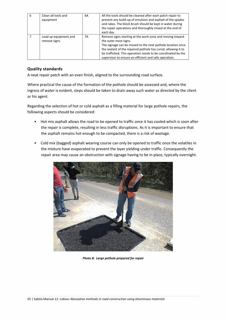
45 | Sabita Manual 12: Labour Absorptive methods in road construction using bituminous materials
6 Clean all tools and equipment
6A
All the tools should be cleaned after each patch repair to prevent any build-up of emulsion and asphalt of the spades and rakes. The block brush should be kept in water during the repair operations and thoroughly rinsed at the end of each day.
7 Load up equipment and remove signs
7A Remove signs starting at the work zone and moving toward the outer most signs. The signage can be moved to the next pothole location once the sealant of the repaired pothole has cured, allowing it to be trafficked. This operation needs to be coordinated by the supervisor to ensure an efficient and safe operation.
Quality standards
A neat repair patch with an even finish, aligned to the surrounding road surface.
Where practical the cause of the formation of the pothole should be assessed and, where the
ingress of water is evident, steps should be taken to drain away such water as directed by the client
or his agent.
Regarding the selection of hot or cold asphalt as a filling material for large pothole repairs, the
following aspects should be considered:
• Hot mix asphalt allows the road to be opened to traffic once it has cooled which is soon after
the repair is complete, resulting in less traffic disruptions. As it is important to ensure that
the asphalt remains hot enough to be compacted, there is a risk of wastage.
• Cold mix (bagged) asphalt wearing course can only be opened to traffic once the volatiles in
the mixture have evaporated to prevent the layer yielding under traffic. Consequently the
repair area may cause an obstruction with signage having to be in place, typically overnight.
Photo 8: Large pothole prepared for repair

46 | Sabita Manual 12: Labour Absorptive methods in road construction using bituminous materials
M 02: POTHOLE REPAIR WITH A FABRICATED ROAD PATCH
Description
This method covers the repair of potholes in black top roads by removal of the asphalt surfacing
where there is no evidence of deep seated pavement failure of the base and / or subbase layer(s).
The replacement material adopted in this method is cement-stabilised gravel of suitable quality with
a prefabricated road patch placed on top, to hold the repair together and to provide a bituminised
wearing course surfacing. Consideration can also be given to the use of the fabricated road patch to
finish off and seal repairs with asphalt, as described in Method M 01.
Potholes should be repaired as soon as possible before they grow bigger – signifying a serious road
traffic hazard – or cause the underlying layers, now exposed to water ingress and strength loss, to
disintegrate.
Requirements
LABOUR PLANT / EQUIPMENT MATERIAL No. Class No. Type No. Description
1 Supervisor/Truck driver 1 Tape measure As req. As alternative to asphalt: Natural gravel, with a PI < 6, suitable for use as a cement-stabilised material. The nominal maximum aggregate size of the gravel should not exceed half (preferably a third) of the required depth to be backfilled.
6 General workers 1 box Crayons As req. Fresh ordinary Portland cement.
2 Traffic controllers 1 Straight edge As req. Factory manufactured road patch, sourced from a reputable supplier, with aggregate applied with a bitumen-rubber binder. Road patches are available in varying aggregate sizes: -5 mm, 7.1 mm, 10 mm, 14 mm, 20 mm and 20 mm choked with 10 mm. Patches are usually available in 1 m x 0.75 m panels. These panels can be pre-cut into smaller panels as required or butt jointed to accommodate larger areas.
2 Wheel barrows As req. Anionic stable mix grade 60% emulsion
4 Picks As req. Water/solvent for cleaning equipment
4 Shovels
1 Block brush
1 Bucket
1 Rake with metal straight edge
2 Brooms (bass)

47 | Sabita Manual 12: Labour Absorptive methods in road construction using bituminous materials
1 Hand stamper
1 Stanley knife or similar
2 Red flags
2 Safety vests
As req. Road signs as per the SARTSM
Method and procedures
ACTIVITY STEP KEY POINTS 1 Secure work area 1A
The work area should be barricaded off in the correct manner to allow for the work to be undertaken while protecting persons in the work zone and allowing safe passage of vehicles, especially where the work is undertaken under traffic.
1B Traffic signs should be set out in accordance with national standards.
2 Prepare the pothole 2A The area that will be removed around the pothole should be marked out using the straight edge and crayons. Allowance should be made for the patch to overlap at least 100 mm on sound surfacing around the repair. The marked area should be made in a rectangular shape with the corners slightly rounded and sides parallel to the road edge. Care should be taken to ensure that the area marked out covers the full extent of the damaged zone.
2B Using a pick and shovel trim and remove cracked material up to the edge of the crayon markings. Ensure that material is removed to allow for a minimum depth of 50 mm or at least twice the nominal maximum aggregate size of the gravel backfill material.
2C The exposed areas should be broomed to remove all loose material and dust to ensure a good bond of the backfilling material to the existing pavement layers.
3 Back filling with stabilised gravel
3A The gravel is stabilised with 1.5% cement by mass, followed by a further treatment of 1:4 dilution of bitumen emulsion for additional waterproofing and facilitating compaction. These materials should be thoroughly mixed in a wheel barrow at above optimum moisture content. The amount of water to be added should take into account the quantity of water in the diluted emulsion.
3B The stabilised gravel is placed into the pothole and compacted with the hand stamper with a finished level flush with the surrounding surfacing.
4 Covering repair with road patch
4A Ideally, the road surface temperature should be 10oC and rising for this operation. If the road temperature is below 10oC, the back of the road patch should be treated with emulsion.
4B The area to be covered with the road patch should be swept clean. Evenly apply the emulsion to the area as marked out on the road surface at a rate of 0.75 l/m2. Once the emulsion has broken i.e. it has turned from brown to black and is still “tacky”, the road patch can be applied.
4C With the paper side uppermost, the road patch is cut to size with a sharp knife through the paper, bent backwards over the aggregate when it will separate on the cut line. The patch panels, aggregate side up, are placed into position over the emulsion coated area. The panels should not overlap if the area is larger than a single panel. For multiple panels, the panels should butt up against each other until the entire area is covered. A light application of emulsion is then applied to the edges of the patch to ensure they are fully sealed off from water ingress and that the panels’

48 | Sabita Manual 12: Labour Absorptive methods in road construction using bituminous materials
edges are securely bonded. The emulsion applied at the edges should be covered with coarse sand or -5 mm dust to absorb any excess emulsion and prevent any pickup from vehicle tyres.
4D All panel off–cuts can be retained for later use. All panels as well as the off-cuts should be stored flat in a cool place.
4E No specialised equipment is required for rolling the patches - an on-site vehicle will suffice. The number of passes should be increased in inclement weather or in an intersection which is exposed to heavy turning traffic action.
4F The repair can be opened to traffic immediately after the sealant has set
5 Clean all tools and equipment
5A All the tools should be cleaned after each patch repair to prevent any build-up of emulsion and asphalt of the spades and rakes. The block brush should be kept in water during the repair operations and thoroughly rinsed at the end of each day.
6 Load up equipment and remove signs
6A Remove signs starting at the work zone and moving toward the outer most signs. The signage can be moved to the next pothole location once the sealant of the repaired pothole has cured, allowing it to be trafficked. This operation needs to be coordinated by the supervisor to ensure an efficient and safe operation.
Quality standard
A neat repair patch with an even finish, aligned to the surrounding road surface.
Where practical the cause of the formation of the pothole should be assessed and, where the
ingress of water is evident, steps should be taken to drain away such water as directed by the client
or his agent.
The emulsion should not drip between patches leaving residual splatter on the roads surface.
To ensure a strong bond between the patch and the existing road surface, the emulsion should be
well mixed and its application rate correct i.e. similar to a coat of paint with no pools or puddles.
When on site, panels should not be placed aggregate-side down on the road surface for extended
periods, particularly at elevated temperatures.
The storage instructions accompanying the road patch should be followed both on- and off-site.
The relevant aggregate size is selected either to match the surrounding seal or to maximise
performance. Larger aggregate sizes would be selected where severe conditions warrant a higher
binder content.
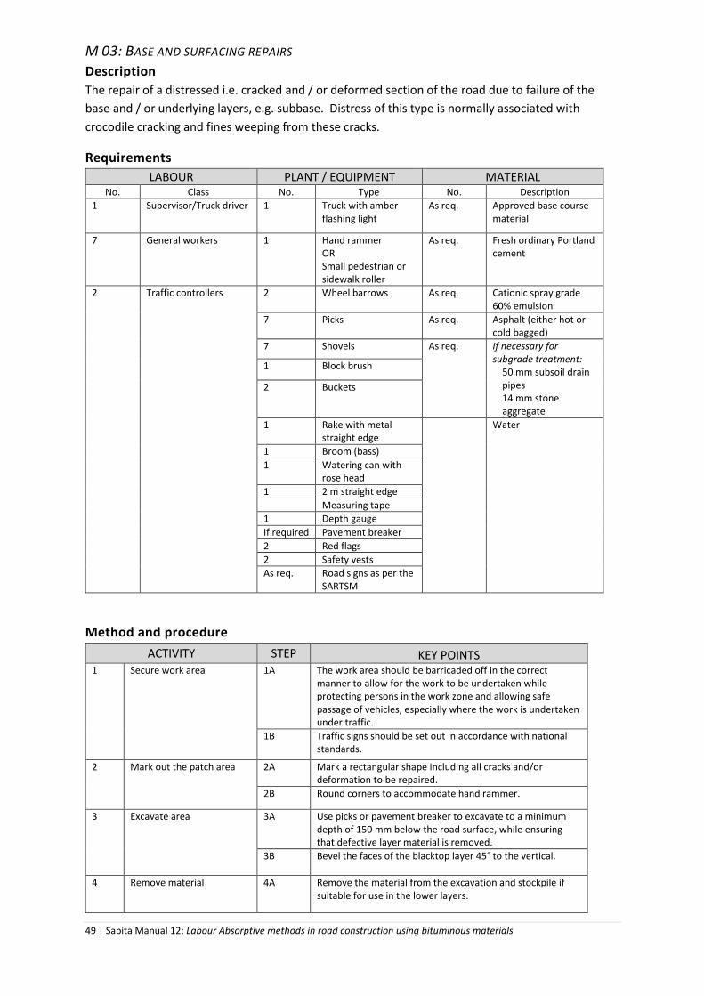
49 | Sabita Manual 12: Labour Absorptive methods in road construction using bituminous materials
M 03: BASE AND SURFACING REPAIRS
Description
The repair of a distressed i.e. cracked and / or deformed section of the road due to failure of the
base and / or underlying layers, e.g. subbase. Distress of this type is normally associated with
crocodile cracking and fines weeping from these cracks.
Requirements
LABOUR PLANT / EQUIPMENT MATERIAL No. Class No. Type No. Description
1 Supervisor/Truck driver 1 Truck with amber flashing light
As req. Approved base course material
7 General workers 1 Hand rammer OR Small pedestrian or sidewalk roller
As req. Fresh ordinary Portland cement
2 Traffic controllers 2 Wheel barrows As req. Cationic spray grade 60% emulsion
7 Picks As req. Asphalt (either hot or cold bagged)
7 Shovels As req. If necessary for subgrade treatment:
50 mm subsoil drain pipes 14 mm stone aggregate
1 Block brush
2 Buckets
1 Rake with metal straight edge
Water
1 Broom (bass)
1 Watering can with rose head
1 2 m straight edge
Measuring tape
1 Depth gauge
If required Pavement breaker
2 Red flags
2 Safety vests
As req. Road signs as per the SARTSM
Method and procedure
ACTIVITY STEP KEY POINTS 1 Secure work area 1A The work area should be barricaded off in the correct
manner to allow for the work to be undertaken while protecting persons in the work zone and allowing safe passage of vehicles, especially where the work is undertaken under traffic.
1B Traffic signs should be set out in accordance with national standards.
2 Mark out the patch area 2A Mark a rectangular shape including all cracks and/or deformation to be repaired.
2B Round corners to accommodate hand rammer.
3 Excavate area 3A Use picks or pavement breaker to excavate to a minimum depth of 150 mm below the road surface, while ensuring that defective layer material is removed.
3B Bevel the faces of the blacktop layer 45° to the vertical.
4 Remove material 4A Remove the material from the excavation and stockpile if suitable for use in the lower layers.
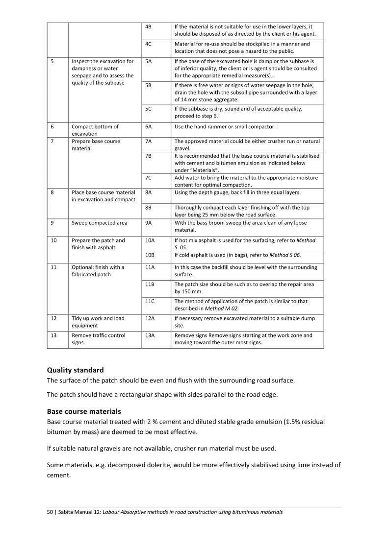
50 | Sabita Manual 12: Labour Absorptive methods in road construction using bituminous materials
4B If the material is not suitable for use in the lower layers, it should be disposed of as directed by the client or his agent.
4C Material for re-use should be stockpiled in a manner and location that does not pose a hazard to the public.
5 Inspect the excavation for dampness or water seepage and to assess the quality of the subbase
5A If the base of the excavated hole is damp or the subbase is of inferior quality, the client or is agent should be consulted for the appropriate remedial measure(s).
5B If there is free water or signs of water seepage in the hole, drain the hole with the subsoil pipe surrounded with a layer of 14 mm stone aggregate.
5C If the subbase is dry, sound and of acceptable quality, proceed to step 6.
6 Compact bottom of excavation
6A Use the hand rammer or small compactor.
7 Prepare base course material
7A The approved material could be either crusher run or natural gravel.
7B It is recommended that the base course material is stabilised with cement and bitumen emulsion as indicated below under “Materials”.
7C Add water to bring the material to the appropriate moisture content for optimal compaction.
8 Place base course material in excavation and compact
8A Using the depth gauge, back fill in three equal layers.
8B Thoroughly compact each layer finishing off with the top layer being 25 mm below the road surface.
9 Sweep compacted area 9A With the bass broom sweep the area clean of any loose material.
10 Prepare the patch and finish with asphalt
10A If hot mix asphalt is used for the surfacing, refer to Method S 05.
10B If cold asphalt is used (in bags), refer to Method S 06.
11 Optional: finish with a fabricated patch
11A In this case the backfill should be level with the surrounding surface.
11B The patch size should be such as to overlap the repair area by 150 mm.
11C The method of application of the patch is similar to that described in Method M 02.
12 Tidy up work and load equipment
12A If necessary remove excavated material to a suitable dump site.
13 Remove traffic control signs
13A Remove signs Remove signs starting at the work zone and moving toward the outer most signs.
Quality standard
The surface of the patch should be even and flush with the surrounding road surface.
The patch should have a rectangular shape with sides parallel to the road edge.
Base course materials
Base course material treated with 2 % cement and diluted stable grade emulsion (1.5% residual
bitumen by mass) are deemed to be most effective.
If suitable natural gravels are not available, crusher run material must be used.
Some materials, e.g. decomposed dolerite, would be more effectively stabilised using lime instead of
cement.

51 | Sabita Manual 12: Labour Absorptive methods in road construction using bituminous materials
The emulsion should be diluted with water in the ratio of one part of emulsion to four parts of water
and mix in the diluted emulsion to approximately 2% over optimum moisture content of the gravel /
crusher run mixture.
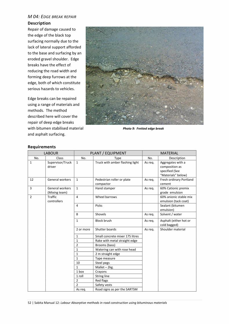
52 | Sabita Manual 12: Labour Absorptive methods in road construction using bituminous materials
M 04: EDGE BREAK REPAIR
Description
Repair of damage caused to
the edge of the black top
surfacing normally due to the
lack of lateral support afforded
to the base and surfacing by an
eroded gravel shoulder. Edge
breaks have the effect of
reducing the road width and
forming deep furrows at the
edge, both of which constitute
serious hazards to vehicles.
Edge breaks can be repaired
using a range of materials and
methods. The method
described here will cover the
repair of deep edge breaks
with bitumen stabilised material Photo 9: Fretted edge break
and asphalt surfacing.
Requirements
LABOUR PLANT / EQUIPMENT MATERIAL No. Class No. Type No. Description
1 Supervisor/Truck driver
1 Truck with amber flashing light As req. Aggregates with a composition as specified (See “Materials” below)
12 General workers 1 Pedestrian roller or plate compactor
As req. Fresh ordinary Portland cement
3 General workers (Mixing team)
1 Hand stamper As req. 60% Cationic premix grade emulsion
2 Traffic controllers
4 Wheel barrows 60% anionic stable mix emulsion (tack coat)
4 Picks Sealant (bitumen emulsion)
8 Shovels As req. Solvent / water
1 Block brush As req. Asphalt (either hot or cold bagged)
2 or more Shutter boards As req. Shoulder material
1 Small concrete mixer 175 litres
1 Rake with metal straight edge
2 Brooms (bass)
1 Watering can with rose head
1 2 m straight edge
1 Tape measure
10 Steel pegs
1 Mallet – 2kg.
1 box Crayons
1 roll String line
2 Red flags
2 Safety vests
As req. Road signs as per the SARTSM
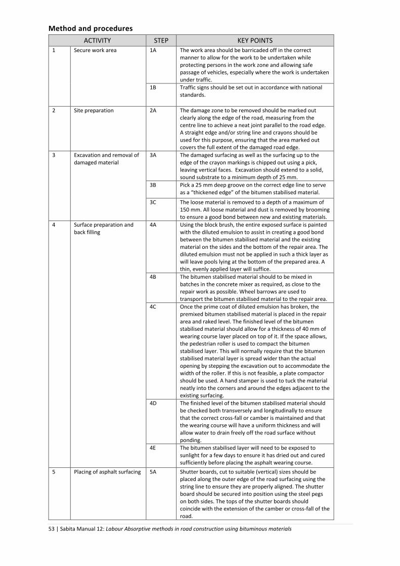
53 | Sabita Manual 12: Labour Absorptive methods in road construction using bituminous materials
Method and procedures
ACTIVITY STEP KEY POINTS 1 Secure work area 1A The work area should be barricaded off in the correct
manner to allow for the work to be undertaken while protecting persons in the work zone and allowing safe passage of vehicles, especially where the work is undertaken under traffic.
1B Traffic signs should be set out in accordance with national standards.
2 Site preparation 2A The damage zone to be removed should be marked out clearly along the edge of the road, measuring from the centre line to achieve a neat joint parallel to the road edge. A straight edge and/or string line and crayons should be used for this purpose, ensuring that the area marked out covers the full extent of the damaged road edge.
3 Excavation and removal of damaged material
3A The damaged surfacing as well as the surfacing up to the edge of the crayon markings is chipped out using a pick, leaving vertical faces. Excavation should extend to a solid, sound substrate to a minimum depth of 25 mm.
3B Pick a 25 mm deep groove on the correct edge line to serve as a “thickened edge” of the bitumen stabilised material.
3C The loose material is removed to a depth of a maximum of 150 mm. All loose material and dust is removed by brooming to ensure a good bond between new and existing materials.
4 Surface preparation and back filling
4A Using the block brush, the entire exposed surface is painted with the diluted emulsion to assist in creating a good bond between the bitumen stabilised material and the existing material on the sides and the bottom of the repair area. The diluted emulsion must not be applied in such a thick layer as will leave pools lying at the bottom of the prepared area. A thin, evenly applied layer will suffice.
4B The bitumen stabilised material should to be mixed in batches in the concrete mixer as required, as close to the repair work as possible. Wheel barrows are used to transport the bitumen stabilised material to the repair area.
4C Once the prime coat of diluted emulsion has broken, the premixed bitumen stabilised material is placed in the repair area and raked level. The finished level of the bitumen stabilised material should allow for a thickness of 40 mm of wearing course layer placed on top of it. If the space allows, the pedestrian roller is used to compact the bitumen stabilised layer. This will normally require that the bitumen stabilised material layer is spread wider than the actual opening by stepping the excavation out to accommodate the width of the roller. If this is not feasible, a plate compactor should be used. A hand stamper is used to tuck the material neatly into the corners and around the edges adjacent to the existing surfacing.
4D The finished level of the bitumen stabilised material should be checked both transversely and longitudinally to ensure that the correct cross-fall or camber is maintained and that the wearing course will have a uniform thickness and will allow water to drain freely off the road surface without ponding.
4E The bitumen stabilised layer will need to be exposed to sunlight for a few days to ensure it has dried out and cured sufficiently before placing the asphalt wearing course.
5 Placing of asphalt surfacing 5A Shutter boards, cut to suitable (vertical) sizes should be placed along the outer edge of the road surfacing using the string line to ensure they are properly aligned. The shutter board should be secured into position using the steel pegs on both sides. The tops of the shutter boards should coincide with the extension of the camber or cross-fall of the road.

54 | Sabita Manual 12: Labour Absorptive methods in road construction using bituminous materials
5B The straight edge should be used to ensure the correct level is obtained. If these levels are too low the resulting dip in the surfacing could lead to damage and material loss over this section of road. Should the section be too high on the outer-edge, it could lead to water ponding which is unsafe and detrimental to the durability of the road surface.
6 Compaction of asphalt surfacing
6A Either hot asphalt or cold asphalt (in bags) may be used. See Methods S 05 & S06 for guidance on receiving and handling material on site.
6B The asphalt, placed in the repair area is raked level. To allow for compaction the loose asphalt should be about 10 mm proud of the existing road surface and the shutter board on the road edge.
6C Compaction should take place from the side of the existing road surface and gradually moving towards the outer edge using the pedestrian roller. The existing road camber or cross fall will assist in achieving the correct fall towards the road edge.
6D The surface of the compacted layer should be tightly knit with no visible cavities or large voids.
6E The decision to use a plate compactor or a pedestrian roller will be depend on the size of the repair work to be undertaken. Bigger repairs will require the pedestrian roller. A hand stamper can be also be used to ensure the joints are all well sealed and that the outer edge is bevelled. Note that vibratory compaction on the existing road layer may damage it.
6F The finished surface level should be checked with the straight edge (and spirit level) in both the longitudinal and transverse directions to ensure that surface drainage is not obstructed.
7 Construction of gravel shoulder support
7A Before commencing with this stage, the repairs should be examined to ensure that they are sufficiently firm to resist the compaction forces they will be exposed to during the gravelling operation.
7B The existing shoulder gravel should be loosened along the length of the repaired area and, if required, additional material should be added. This shoulder gravel is placed and compacted over the bitumen stabilised material that protrudes under the wearing course edge so as to support the actual wearing course and prevent the edge break from recurring.
The gravel is then moistened and compacted flush with the outer surfacing. Care should be taken to ensure that this operation does not disturb or damage the new repairs.
8 Sealing of surface joints 8A After all loose material has been swept from the surface the sealant should be painted over the surface to seal off all cavities as well as the joint between the existing surfacing and the repaired area. This will ensure that the repaired area is waterproof and will not allow water to seep into the repaired edge break.
8B A sprinkling of – 5 mm dust or sand can be placed over the sealant to assist in the drying process if it has been over-applied.
9 Cleaning up 9A All the tools should be cleaned after each edge break repair to prevent any build-up of emulsion and asphalt of the spades and rakes. The block brush should be kept in water during the repair operations and thoroughly rinsed at the end of each day.
10 Remove traffic control signs
10A Remove signs starting at the work zone and moving toward the outer most signs.

55 | Sabita Manual 12: Labour Absorptive methods in road construction using bituminous materials
Materials
Bitumen stabilised material consists of a combination of aggregates and 60% cationic premix grade
emulsion, mixed 1 part to 8 parts by volume of the aggregate combination. While the grading
envelope of the aggregates would normally be specified, generally 1 part of 14 mm size, 2 parts of
7.1 mm size and 1 part of crusher dust may well meet such a grading requirement.
Where prevailing conditions (e.g. climate, layer thickness) may retard the setting of the bitumen
stabilised material to an unacceptable level especially during emergency repairs, consideration
should be given to the use of quick setting emulsions supplied by a reputable firm.
Quality standard
The road edge is reinstated to its original position and neither widened nor narrowed.
The surface of the repaired area should be a continuation of the existing road cross fall.
Sufficient side support should be provided along the edge of the wearing course layer.
The gravel shoulder should be shaped so as to allow water to drain away from the road surface.

56 | Sabita Manual 12: Labour Absorptive methods in road construction using bituminous materials
M 05: CRACK SEALING (LESS THAN 5 MM WIDTH)
Description
The sealing of cracks in black top road surfaces, less than 5 mm in width, using cold applied bitumen
emulsion. The method described applies to well defined cracks, not necessarily traffic associated
and which could be associated with shrinkage and or ageing of pavement layers.
Requirements
LABOUR PLANT / EQUIPMENT MATERIAL No. Class No. Type No. Description
1 Supervisor/Truck driver 1 Truck with amber flashing light
As req. Modified bitumen emulsion crack sealant obtained from a reputable supplier 8 General workers 2 Wheel barrows
2 General workers (traffic controllers
2 Wire brushes
2 Brooms (bass)
2 Cans or applicators with spouts
Crayons or spray cans
1 Compressor
2 Red flags
2 Safety vests
As req. Road signs as per the SARTSM
Method and procedures
ACTIVITY STEP KEY POINTS 1 Secure work area 1A The work area should be barricaded off in the correct
manner to allow for the work to be undertaken while protecting persons in the work zone and allowing safe passage of vehicles, especially where the work is undertaken under traffic.
1B Traffic signs should be set out in accordance with national standards.
2 Site preparation 2A The area to be repaired should be inspected together with the client or his agent and all the cracks that require sealing should be marked using the canyons or spray cans of paint.
2B The work area should be swept clean of all loose material and dust. The wire brush should be used to loosen the material that is lodged in the cracks. This material needs to be swept out and away from the crack.
2C Next the compressor should be used to blow the cracks clean of all dust and debris to ensure the sealant can adhere to both sides of the crack. Notice should be taken of the wind direction so as not to have the dust blown back into the cracks.
3 Sealing of cracks 3A The sealant is poured into the cracks from the can or applicator that should have a spout to help direct the emulsion into the crack.
3B The emulsion should be brushed into the finer cracks the soft bristled brush.
3C The emulsion can be diluted with up to 10% water to assist penetration into fine cracks.
3D After sealing, the emulsion should be allowed to set.
3E If the emulsion remains tacky on the surface, a thin blinding layer of -5 mm crusher dust or course sand can be swept

57 | Sabita Manual 12: Labour Absorptive methods in road construction using bituminous materials
over the cracks to absorb the residue. Excess material should be swept from the road surface
4 Cleaning up 4A All the tools should be cleaned to prevent any build-up of emulsion. If the emulsion has not yet set on the implements, water can be used; otherwise mineral turpentine or paraffin is required.
5 Remove traffic control signs
5A Remove signs starting at the work zone and moving toward the outer most signs.
Quality standard
Sealed cracks should be watertight, look neat and level with the existing road surface.
It is important to note that, before sealing, the cracks should be clean and free of dust. If not, the
bitumen emulsion will not be able to adhere to both sides of the crack, allowing moisture to
penetrate the crack which will defeat the purpose of the operation
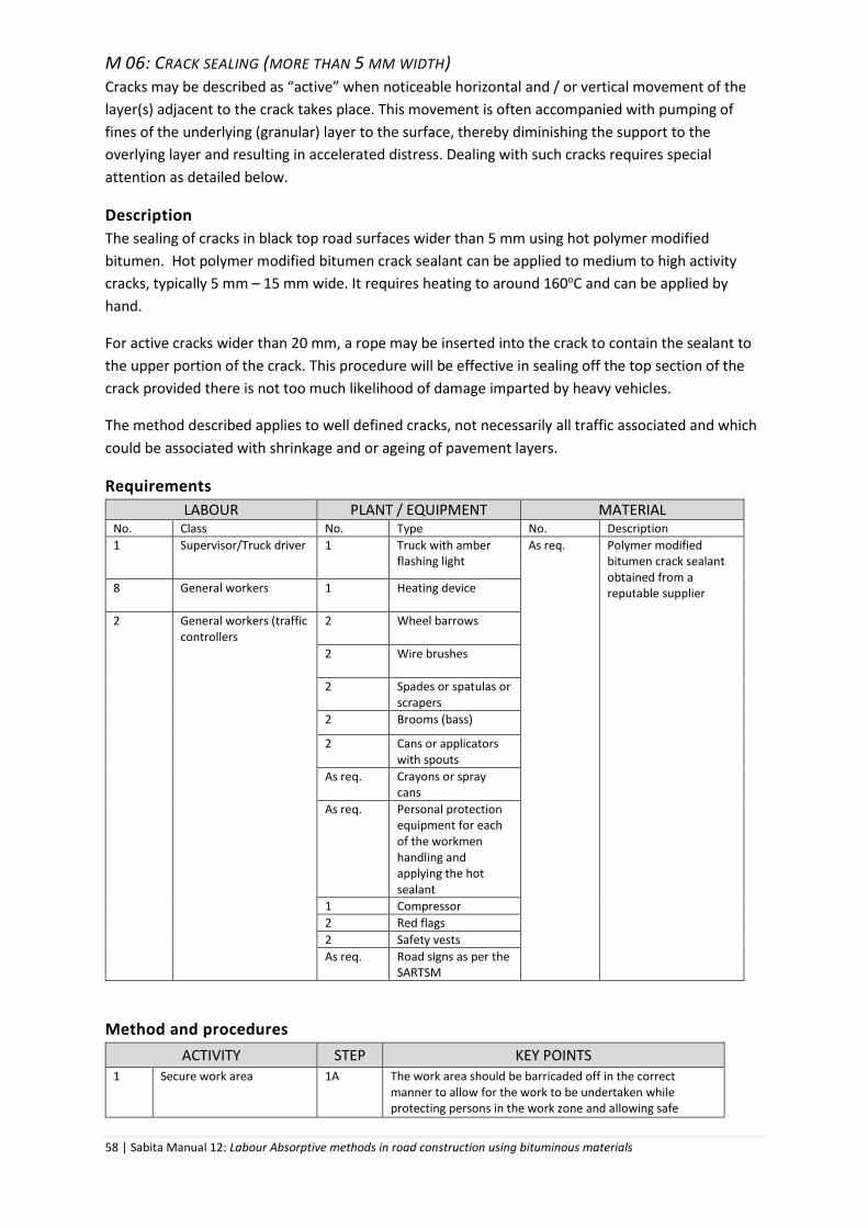
58 | Sabita Manual 12: Labour Absorptive methods in road construction using bituminous materials
M 06: CRACK SEALING (MORE THAN 5 MM WIDTH) Cracks may be described as “active” when noticeable horizontal and / or vertical movement of the
layer(s) adjacent to the crack takes place. This movement is often accompanied with pumping of
fines of the underlying (granular) layer to the surface, thereby diminishing the support to the
overlying layer and resulting in accelerated distress. Dealing with such cracks requires special
attention as detailed below.
Description
The sealing of cracks in black top road surfaces wider than 5 mm using hot polymer modified
bitumen. Hot polymer modified bitumen crack sealant can be applied to medium to high activity
cracks, typically 5 mm – 15 mm wide. It requires heating to around 160oC and can be applied by
hand.
For active cracks wider than 20 mm, a rope may be inserted into the crack to contain the sealant to
the upper portion of the crack. This procedure will be effective in sealing off the top section of the
crack provided there is not too much likelihood of damage imparted by heavy vehicles.
The method described applies to well defined cracks, not necessarily all traffic associated and which
could be associated with shrinkage and or ageing of pavement layers.
Requirements
LABOUR PLANT / EQUIPMENT MATERIAL No. Class No. Type No. Description
1 Supervisor/Truck driver 1 Truck with amber flashing light
As req. Polymer modified bitumen crack sealant obtained from a reputable supplier 8 General workers 1 Heating device
2 General workers (traffic controllers
2 Wheel barrows
2 Wire brushes
2 Spades or spatulas or scrapers
2 Brooms (bass)
2 Cans or applicators with spouts
As req. Crayons or spray cans
As req. Personal protection equipment for each of the workmen handling and applying the hot sealant
1 Compressor
2 Red flags
2 Safety vests
As req. Road signs as per the SARTSM
Method and procedures
ACTIVITY STEP KEY POINTS 1 Secure work area 1A The work area should be barricaded off in the correct
manner to allow for the work to be undertaken while protecting persons in the work zone and allowing safe

59 | Sabita Manual 12: Labour Absorptive methods in road construction using bituminous materials
passage of vehicles, especially where the work is undertaken under traffic.
1B Traffic signs should be set out in accordance with national standards.
2 Site preparation 2A The area to be repaired should be inspected together with the client or his agent and all the cracks that require sealing should be marked using the canyons or spray cans of paint.
2B The work area should be swept clean of all loose material and dust. The wire brush should be used to loosen the material that is lodged in the cracks. This material needs to be swept out and away from the crack.
2C Next the compressor should be used to blow the cracks clean of all dust and debris to ensure the sealant can adhere to both sides of the crack. Notice should be taken of the wind direction so as not to have the dust blown back into the cracks.
3 Sealing of cracks 3A The polymer modified bitumen crack sealant should be heated in a safe manner to the required temperature - generally 160oC. The heated polymer modified bitumen is then transferred to a specialised applicator or into a pouring can.
3B The sealant is poured into the cracks from the can or applicator that should have a spout to help direct the emulsion into the crack. Ensure that the bitumen if fluid enough to penetrate into the crack and not just lie on the surface. Allow the polymer modified bitumen to harden.
3C Using a hot scraper, spatula or spade excess material, protruding above the crack, should be removed.
4 Cleaning up 4A All the tools should be cleaned to prevent any build-up of bitumen using mineral turpentine or paraffin.
5 Remove traffic control signs
5A Remove signs starting at the work zone and moving toward the outer most signs.
Photo 10: Applying sealant to prepared crack
Quality standard
Sealed cracks should be watertight, look neat and level with the existing road surface

60 | Sabita Manual 12: Labour Absorptive methods in road construction using bituminous materials
It is important to note that, before sealing, the cracks should be clean and free of dust. If not, the
polymer modified bitumen will not be able to adhere to both sides of the crack, allowing moisture to
penetrate the crack which will defeat the purpose of the operation.
If deemed necessary, weed killer should be applied to the cracks before applying the polymer
modified bitumen sealant.
M 07: CRACK SEALING WITH A GEOTEXTILE FABRIC
Description
Covering and sealing cracks in the black top surface with a geotextile fabric saturated in a
bituminous binder. This procedure is effective if the cracks are closely spaced and localised and the
operation is considered to be a holding action before a suitable wearing course is applied as a more
permanent seal.
Requirements
LABOUR PLANT / EQUIPMENT MATERIAL No. Class No. Type No. Description
1 Supervisor/Truck driver 1 Truck with amber flashing light
As req. Modified bitumen emulsion obtained from a reputable supplier
8 General workers 1 Pedestrian static roller
As req. A non-woven geotextile fabric of suitable thickness and strength as required by the client or his agent for the specific application, sourced through a reputable supplier
2 General workers (traffic controllers)
2 Wheel barrows As req. Coarse sand: - 5 mm dust or 7.1 mm stone chippings to cover the patch and to tie it in with the existing surfacing.
2 Wire brushes
2 Squeegees
2 Brooms (bass)
1 Knife or scissors
2 Cans or applicators with spouts
As req. Crayons or spray cans
1 Compressor
As req. Water and / or solvent for cleaning
2 Red flags
2 Safety vests
As req. Road signs as per the SARTSM
Method and procedures
ACTIVITY STEP KEY POINTS 1 Secure work area 1A The work area should be barricaded off in the correct
manner to allow for the work to be undertaken while protecting persons in the work zone and allowing safe passage of vehicles, especially where the work is undertaken under traffic.
1B Traffic signs should be set out in accordance with national standards.

61 | Sabita Manual 12: Labour Absorptive methods in road construction using bituminous materials
2 Site preparation 2A The area to be repaired should be inspected together with the client or his agent and all the cracks that require sealing should be marked using, the canyons or spray cans of paint.
2B Cracks wider than 5 mm will need to be pre-treated with a crack sealer. (See Method M 06.) If pumping of water is evident at the cracks it may be necessary to install some subsurface drainage. This will need to be done on the advice and standards of the client or his agent.
2C The work area should be swept clean of all loose material and dust. The wire brush should be used to loosen the material that is lodged in the cracks. This material needs to be swept out and away from the crack.
3 Applying the geotextile fabric over the cracks
3A The geotextile fabric should be cut to the required size to enable it to extend at least 100 mm beyond the crack, in terms of both width and length.
3B The precise area to be covered by the fabric should be painted with the modified bitumen emulsion at a rate of 1 l/m2 of patch using either the block brush or squeegee.
3C For weathered surfaces the application rate should be increased by 0.1 – 0.3 l/m2. For open textured surfaces the application should be increased by 0.3 – 0.5 l/m2.
3D The exact additional application rates should be ascertained from the client or his agent.
3E The cut geotextile fabric patch is then placed onto the painted emulsion and smoothed down with the squeegee while pressing the geotextile fabric into the emulsion. The edges of the geotextile fabric should be properly stuck to the emulsion.
3F The fabric is then rolled with a loaded wheelbarrow (e.g. two cement pockets).
4 Finishing the surface treatment of the fabric
4A The surface of the patch can be saturated with emulsion prior to the application of stone chippings or sand, if so required by the client or his agent.
4B The application rate will depend on the surface finish specified - either sand, -5 mm dust, or 7.1 mm stone chippings applied at a rate will depend on the aggregate size and shape and specified by the client or his agent.
4C Excess material that does not adhere to the emulsion must be swept off the repaired area and removed from the road surface. The surfacing aggregates should be rolled with a static roller to ensure they are properly embedded and correctly orientated.
4 Cleaning up 4A All the tools should be cleaned to prevent any build-up of bitumen emulsion using either water if the emulsion has not yet set; otherwise mineral turpentine or paraffin.
5 Remove traffic control signs
5A Remove signs starting at the work zone and moving toward the outer most signs.
Quality standard
All cracks in the treatment area are properly sealed and, where specified, the surface area of the
fabric treated with either stone chips or sand presents a well-knit texture, flush with the existing
surfacing.
The application rate of the emulsion should be such as to ensure sufficient impregnation of the
geotextile fabric and proper bonding of the fabric to the existing road surface.
The cracks being covered should be inspected for the presence of excessive moisture as such
moisture can adversely affect the adhesion of the geotextile fabric to the surfacing.

62 | Sabita Manual 12: Labour Absorptive methods in road construction using bituminous materials
The modified bitumen emulsion should not be cut back as the volatiles may get trapped in the
geotextile fabric during hot weather making the binder softer than required which can lead to
premature distress of the repaired area.
On steep gradients and under certain climatic conditions sliding of the geofabric materials can occur.
Their use and the binder to be applied under such conditions should be carefully considered by the
client or his agent.

63 | Sabita Manual 12: Labour Absorptive methods in road construction using bituminous materials
M 08: CRACK SEALING USING A FABRICATED ROAD PATCH
Description
Covering and sealing cracks in the black top surface with a fabricated road patch consisting of a
paper on which a modified binder holds bitumen-precoated aggregates of various sizes. The repair
will seal off the crack against the ingress of water and serve as a means of tying the surfacing
together and prevent any further loss of fines through the cracks as a result of the action of traffic.
This method for covering active cracks on a road surface is effective if the cracks are closely spaced
and localised
Requirements
LABOUR PLANT / EQUIPMENT MATERIAL No. Class No. Type No. Description
1 Supervisor/Truck driver 1 Truck with amber flashing light
As req. Either cationic or anionic bitumen emulsion (60 or 65%) sourced from a reputable supplier
8 General workers 2 Wheel barrows As req. Factory fabricated road patch. These products are available with various stone chip nominal sizes ranging from 5 mm to 20 mm and 20 mm choked with 10 mm chips. Generally road patches are available in 1.0 x 0.75 m panels which can be cut into smaller panels as required. Panels can be butt jointed to accommodate larger areas. Such products are to be sourced from a reputable supplier
2 General workers (traffic controllers)
2 Brooms (bass) Coarse sand, - 5 mm dust or 7.1 mm stone chippings to cover the patch and to tie it in with the existing surfacing as advised by the client or his agent
2 Stanley knives or similar
1 Straight edge
As req. Crayons or spray cans
2 Red flags
2 Safety vests
As req. Road signs as per the SARTSM
Method and procedures
ACTIVITY STEP KEY POINTS 1 Secure work area 1A The work area should be barricaded off in the correct
manner to allow for the work to be undertaken while protecting persons in the work zone and allowing safe passage of vehicles, especially where the work is undertaken under traffic.
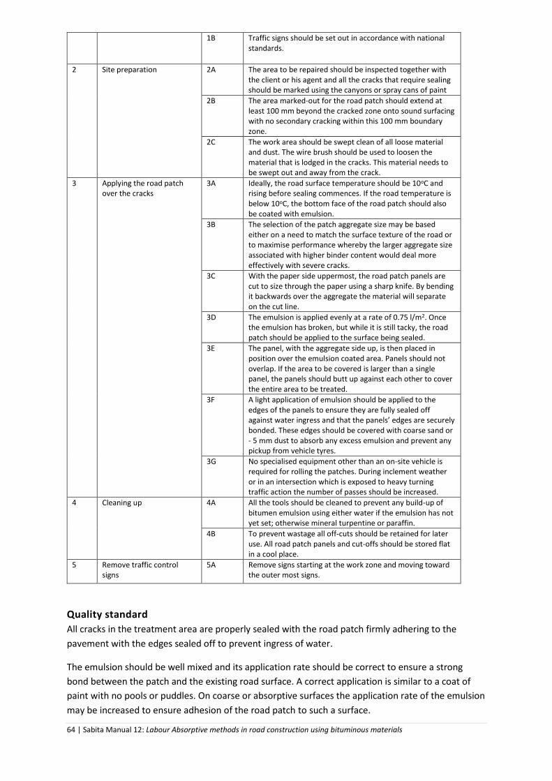
64 | Sabita Manual 12: Labour Absorptive methods in road construction using bituminous materials
1B Traffic signs should be set out in accordance with national standards.
2 Site preparation 2A The area to be repaired should be inspected together with the client or his agent and all the cracks that require sealing should be marked using the canyons or spray cans of paint
2B The area marked-out for the road patch should extend at least 100 mm beyond the cracked zone onto sound surfacing with no secondary cracking within this 100 mm boundary zone.
2C The work area should be swept clean of all loose material and dust. The wire brush should be used to loosen the material that is lodged in the cracks. This material needs to be swept out and away from the crack.
3 Applying the road patch over the cracks
3A Ideally, the road surface temperature should be 10oC and rising before sealing commences. If the road temperature is below 10oC, the bottom face of the road patch should also be coated with emulsion.
3B The selection of the patch aggregate size may be based either on a need to match the surface texture of the road or to maximise performance whereby the larger aggregate size associated with higher binder content would deal more effectively with severe cracks.
3C With the paper side uppermost, the road patch panels are cut to size through the paper using a sharp knife. By bending it backwards over the aggregate the material will separate on the cut line.
3D The emulsion is applied evenly at a rate of 0.75 l/m2. Once the emulsion has broken, but while it is still tacky, the road patch should be applied to the surface being sealed.
3E The panel, with the aggregate side up, is then placed in position over the emulsion coated area. Panels should not overlap. If the area to be covered is larger than a single panel, the panels should butt up against each other to cover the entire area to be treated.
3F A light application of emulsion should be applied to the edges of the panels to ensure they are fully sealed off against water ingress and that the panels’ edges are securely bonded. These edges should be covered with coarse sand or - 5 mm dust to absorb any excess emulsion and prevent any pickup from vehicle tyres.
3G No specialised equipment other than an on-site vehicle is required for rolling the patches. During inclement weather or in an intersection which is exposed to heavy turning traffic action the number of passes should be increased.
4 Cleaning up 4A All the tools should be cleaned to prevent any build-up of bitumen emulsion using either water if the emulsion has not yet set; otherwise mineral turpentine or paraffin.
4B To prevent wastage all off-cuts should be retained for later use. All road patch panels and cut-offs should be stored flat in a cool place.
5 Remove traffic control signs
5A Remove signs starting at the work zone and moving toward the outer most signs.
Quality standard
All cracks in the treatment area are properly sealed with the road patch firmly adhering to the
pavement with the edges sealed off to prevent ingress of water.
The emulsion should be well mixed and its application rate should be correct to ensure a strong
bond between the patch and the existing road surface. A correct application is similar to a coat of
paint with no pools or puddles. On coarse or absorptive surfaces the application rate of the emulsion
may be increased to ensure adhesion of the road patch to such a surface.

65 | Sabita Manual 12: Labour Absorptive methods in road construction using bituminous materials
The cracks being covered should be inspected for the presence of excessive moisture as such
moisture can adversely affect the adhesion of the geotextile fabric to the surfacing.
Storage instructions of the fabricated patches should be followed both on and off site.

66 | Sabita Manual 12: Labour Absorptive methods in road construction using bituminous materials
M 09: TRENCH REINSTATEMENT
Description
The backfilling of a trench excavated across a roadway to accommodate services. The backfill will
consist of various materials to provide adequate strength and finish. The width of the trench will
vary in accordance with the number and nature of the services to be accommodated.
The method given deals only with the reinstatement of the trench with backfill layers and the
wearing course; it does not cover the excavation and laying of services. However, where
appropriate and depending on the depth of the trench, consideration should be given to stepping
the excavation to facilitate compaction during backfill operations.
The main purpose of this method statement is to emphasise the attention to detail required during
reinstatement to prevent traffic related damage to the installed services and minimize subsequent
subsidence and distress of the reinstatement causing an unacceptable depression in the road
surface once reopened to traffic. Such depressions are normally due to shoddy workmanship,
insufficient attention to material quality and inadequate compaction throughout the entire
backfilling operation.
Requirements
LABOUR PLANT / EQUIPMENT MATERIAL No. Class No. Type No. Description
1 Supervisor/Truck driver 1 Truck with amber flashing light
As req. Backfill material Pavement controlled layers: Base course, subbase and selected subgrade material as specified by the client or his agent or materials that at least match the quality of the adjacent corresponding layers. For expediency, upper layers may be stabilised with cement and / or bitumen emulsion and asphalt base may be used. In such cases authorisation by the client or his agent should be sought. The client or his agent should specify the both the quality of materials to be used in the various zones of the back-fill and the degree of compaction required. Back-fill material to be placed around the services and in the zone below the control layers, i.e. the subgrade: graded river or crushed sand
6 General workers 2 Wheel barrows
2 General workers (traffic controllers)
1 Tape measure
1 box Crayons
1 Block brush
1 Straight edge
2 Brooms (bass)
4 Shovels
2 Rakes
1 Hand stamper
Compaction equipment (pedestrian vibratory roller or vibratory plate compactor or vibratory rammer)
1 Water tank or cart to moisten back fill material
2 Red flags
2 Safety vests

67 | Sabita Manual 12: Labour Absorptive methods in road construction using bituminous materials
As req. Road signs as per the SARTSM
As req. Asphalt Wearing course: Either hot asphalt or cold asphalt (in bags) can be used. A dense graded material with a nominal max. aggregate size of 10 mm is recommended for ease of handling and compaction. Base course (where applicable): Dense graded hot mix asphalt with a nominal max. aggregate size of 28 mm is recommended. Receipt and handling of asphalt on site should be in accordance with Method S 05.
As req. Diluted 60% anionic stable mix grade bitumen emulsion is recommended as a prime coat for the asphalt surfacing as it breaks faster and allows the work to be completed in one operation.
As req. Solvent or water for cleaning
As req. Sealant – usually a bitumen emulsion to cover the edges of the surfacing to prevent moisture ingress.
Method and procedures
ACTIVITY STEP KEY POINTS
1 Secure work area 1A To accommodate traffic this work is normally carried out in half widths. The work area should be barricaded off in the correct manner to allow for the work to be undertaken while protecting persons in the work zone and allowing safe passage of vehicles, especially where the work is undertaken under traffic.
1B Traffic signs should be set out in accordance with national standards.
2 Site preparation 2A The area will already have been excavated and the services laid and, where appropriate, protected.
2B To prevent direct ingress of water into the reinstated zone through cracks that may occur in the surfacing at the edge of the trench, the existing surfacing should be chipped out in a straight line, parallel to the trench, at least 150mm from the edge of the trench.
3 Back filling the trench with fill material
3A It is the responsibility of the services laying team to ensure that the bedding of the services is of adequate quality to prevent undue settlement, displacement and damage during backfilling.
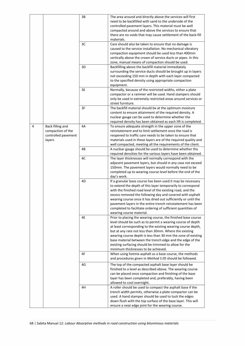
68 | Sabita Manual 12: Labour Absorptive methods in road construction using bituminous materials
3B The area around and directly above the services will first need to be backfilled with sand to the underside of the controlled pavement layers. This material must be well compacted around and above the services to ensure that there are no voids that may cause settlement of the back-fill materials.
3C Care should also be taken to ensure that no damage is caused to the service installation. No mechanical vibratory compaction equipment should be used less than 400mm vertically above the crown of service ducts or pipes. In this zone, manual means of compaction should be used.
3D Backfilling above the backfill material immediately surrounding the service ducts should be brought up in layers not exceeding 150 mm in depth with each layer compacted to the specified density using appropriate compaction equipment.
3E Normally, because of the restricted widths, either a plate compactor or a rammer will be used. Hand stampers should only be used in extremely restricted areas around services or street furniture.
3F The backfill material should be at the optimum moisture content to ensure attainment of the required density. A nuclear gauge can be used to determine whether the required density has been obtained as each lift is completed.
4 Back filling and compaction of the controlled pavement layers
4A To ensure adequate strength in the upper zone of the reinstatement and to limit settlement once the road is reopened to traffic care needs to be taken to ensure that materials used in these layers are of the required quality and well compacted, meeting all the requirements of the client.
4B A nuclear gauge should be used to determine whether the required densities for the various layers have been obtained.
4C The layer thicknesses will normally correspond with the adjacent pavement layers, but should in any case not exceed 150mm. The pavement layers would normally need to be completed up to wearing course level before the end of the day’s work.
4D If a granular base course has been used it may be necessary to extend the depth of this layer temporarily to correspond with the finished road level of the existing road, and the excess removed the following day and covered with asphalt wearing course once it has dried out sufficiently or until the pavement layers in the entire trench reinstatement has been completed to facilitate ordering of sufficient quantities of wearing course material.
4E Prior to placing the wearing course, the finished base course level should be such as to permit a wearing course of depth at least corresponding to the existing wearing course depth, but at any rate not less than 30mm. Where the existing wearing course depth is less than 30 mm the zone of existing base material between the trench edge and the edge of the existing surfacing should be trimmed to allow for the minimum thicknesses to be achieved.
4F When using hotmix asphalt as a base course, the methods and procedures given in Method S 05 should be followed.
4G The top of the compacted asphalt base layer should be finished to a level as described above. The wearing course can be placed once compaction and finishing of the base layer has been completed and, preferably, having been allowed to cool overnight.
4H A roller should be used to compact the asphalt base if the trench width permits, otherwise a plate compactor can be used. A hand stamper should be used to tuck the edges down flush with the top surface of the base layer. This will ensure a neat edge joint for the wearing course.

69 | Sabita Manual 12: Labour Absorptive methods in road construction using bituminous materials
5 Placing and compacting wearing course asphalt
5A Either hot or bagged cold mix asphalt can be used as per Methods S 05 and S 06, respectively.
6 Remove traffic control signs
6A Remove signs starting at the work zone and moving toward the outer most signs.
Quality standard
It is critically important to ensure that level of compaction of the backfilling materials and layers
meets the minimum requirements uniformly to prevent undue subsidence of the reinstatement.
Experience has shown that all too often the backfilling operation is done in a rushed and slipshod
manner, sometimes with insufficient supervision, resulting in a subsequent unacceptable depression
of the surface requiring further repair in and around the original trench crossing dealing with rutting,
a deformed trench and potholes that form in the zone adjoining the trenched area.
Compaction of the wearing course must be accomplished in such a manner as not to damage the
surrounding wearing course which could result in cracks leading to potholes forming around the
edges of the trench crossing repair.
Regarding the selection of hot or cold mix wearing course asphalt, a number of factors need to be
assessed, given the particular circumstances pertaining to work:
The use of hotmix asphalt wearing course allows the road to be opened to traffic
immediately after the repair is complete which facilitates traffic accommodation. Its use
does, however, require that the material is handled in such a way as to ensure that it
remains hot enough during the operation for it to be adequately compacted and so to avoid
wastage
While the use of cold mix asphalt enables one to limit wastage, not being able to open the
reinstatement to traffic immediately could pose a serious disadvantage that needs to be
assessed.
Proper compaction of the material is vital. Compaction plant should be selected carefully to give the
best results on the material used. Specialised equipment may sometimes be required for narrow
trenching or restricted sites but the following plant is likely to be the most commonly used means of
compaction:
hand rammer - used for the compaction of all material where access is severely restricted,
e.g. around underground services or street furniture. However, this type of equipment
should not be used as a substitute for mechanical compaction equipment
vibratory tamper - easily transported and handled and especially suitable for narrow
trench-work. Delivers between 450 and 650 blows per minute through a small plate to effect
compaction. Its use is not recommended for the compaction of base or wearing course
materials
vibratory roller - the preferred method of compaction of bituminous materials. It may be
single or twin drum. It is not suitable in small and/or narrow excavations with restricted
access
vibratory plate compactor - available in a range of weights and sizes of plate. It is suitable
for compaction in trenches. Its use on bituminous materials will not produce a good surface
finish.