laboratory investigation of variable speed...
TRANSCRIPT

General rights Copyright and moral rights for the publications made accessible in the public portal are retained by the authors and/or other copyright owners and it is a condition of accessing publications that users recognise and abide by the legal requirements associated with these rights.
• Users may download and print one copy of any publication from the public portal for the purpose of private study or research. • You may not further distribute the material or use it for any profit-making activity or commercial gain • You may freely distribute the URL identifying the publication in the public portal
If you believe that this document breaches copyright please contact us providing details, and we will remove access to the work immediately and investigate your claim.
Downloaded from orbit.dtu.dk on: Jun 16, 2018
LABORATORY INVESTIGATION OF VARIABLE SPEED CONTROL OF SYNCHRONOUSGENERATOR WITH A BOOST CONVERTER FOR WIND TURBINE APPLICATIONS
Sharma, Ranjan; Rasmussen, Tonny Wederberg
Published in:EWEC2008
Publication date:2008
Document VersionPublisher's PDF, also known as Version of record
Link back to DTU Orbit
Citation (APA):Sharma, R., & Rasmussen, T. W. (2008). LABORATORY INVESTIGATION OF VARIABLE SPEED CONTROLOF SYNCHRONOUS GENERATOR WITH A BOOST CONVERTER FOR WIND TURBINE APPLICATIONS. InEWEC2008 (1 ed., Vol. Scientific Proceedings). Brussels, Belgium: European Wind Energy Association (EWEA).

Laboratory Investigation of Variable Speed Control ofSynchronous Generator With a Boost Converter for Wind
Turbine Applications
Ranjan Sharma Tonny W. RasmussenTechnical University of Denmark Technical University of Denmark
[email protected] [email protected]
Abstract
This paper includes the experimental and simu-lated results of variable speed control of a syn-chronous generator. To achieve controlled vari-able speed operation, the synchronous generatoris loaded with a three phase rectifier and a boostconverter. The terminal voltage of the genera-tor can be controlled from the converter’s duty cy-cle if output voltage of the converter is kept con-stant. This constant voltage is achieved with thehelp of a grid side inverter. As the speed and theterminal voltage of the generator are directly re-lated to each other, its speed can be controlledfor a given torque. An experimental setup of a7.5KV A generator is prepared to verify system re-sponse. Some interesting aspects concerning dis-tributed capacitance of the generator winding andnon-linear speed vs duty-cycle response are ob-served. Cause and effect of such problems arediscussed in this paper. Efficiency measurementshowed some promising results and the overallsystem response is found positive. Also a Matlabsimulation is performed for single turbine systemincluding grid side inverter. The results are pre-sented here in brief.
Keywords: Wind turbines, variable speed, syn-chronous generator, boost converter
1 Introduction
Variable speed wind turbines have been of majorinterest recently due to its superiority over fixedspeed on different aspects. Some advantages arethat, a variable speed wind turbine together withpitch control can be used for smooth power reg-ulation, mechanical stresses on the turbine com-ponents can be reduced, complexity of the pitch
control can reduced and theoretically the annualenergy production will be improved.
Variable speed turbines equipped with double-fedinduction machine or simply induction machine arecommon. The focus in this paper will be on usingsynchronous generator controlled with boost con-verter, initially proposed in [1]. The synchronousgenerator can either be a permanent magnet orwound rotor type. A wound rotor type generatorwill have an extra degree of freedom in terms offield excitation, but at the same time, loss in the ro-tor circuit will be present. In the other hand, per-manent magnet generators are relatively expen-sive. However, the proposed system to control thespeed of a synchronous generator will require lessnumber of switching devices compared to the con-trol of induction or double fed induction generators.Hence, this will reduce switching and conductinglosses. Many wind turbines in a farm can be con-nected to a common dc link point as shown in fig-ure (1). The power transmission will be throughHVDC (high voltage direct current) lines and theIGBT equipped main inverter will connect the farmto the grid. The proposed configuration of a windfarm will also allow individual control of each tur-bine with maximum power point tracking [2]. Withthe help of the boost converter duty cycle, powerfrom the generator can be regulated. Dependingupon the power available in the wind, the duty cy-cle can be varied to control the speed. During theprocess, the electrical power to the grid will be con-stant and thus the power quality is improved.
2 Speed Control of Syn-chronous Generator
If a single generator system is considered, theequivalent diagram of the system can be repre-sented as shown in figure 2. The dc side can be
1

Figure 1: Proposed wind farm connection diagram
represented by variable dc voltage whose magni-tude can be controlled by a boost converter. Sincethe output voltage of the boost converter is con-stant, any change in its duty cycle will force changethe input dc voltage. The terminal voltage of thegenerator is determined by this variable dc volt-age. Since the voltage across and current througha diode are in phase, the load and the rectifier canbe assumed to draw unity power factor current. Forthe magnitude of power transferred from the gen-erator to the load, the losses in the rectifier can beneglected for the analytical purpose.
Figure 2: Synchronous generator with rectifier andvoltage load
For a synchronous generator, either permanentmagnet or wound rotor supplied with a fixed fieldcurrent, the generator excitation voltage can bewritten as,
Eaf = Kφωe (1)
Where ωe = 2πf is the electrical angular frequencyand Kφ = 4.44φafNKw is a generator constantprovided that φaf is constant.
So for a variable speed operation, generator volt-age equation can thus be written as,
Vpωe
∠0o + jLsIp = Kφ∠δo (2)
Where δ is the power angle, Vp is the phase volt-age, Ip is the current and Ls is the inductance ofthe generator. The phasor diagram representationof the generator is shown in figure 3.
Figure 3: Phasor diagram
The DC values after the rectifier can be written interms of generator AC voltage and current.
Vdc =3√
6π
Vp (3)
Idc =π√6Ip (4)
From the phasor diagram, phase current of thegenerator can be written as,
Ip =Kφ
Ls
√[1−
( πVdc
3√
6/ωe
K φ
)]Therefore the power and torque equations will beas follows,
P = 3VpIp
= 3πVdc
3√
6Kφ
Ls
√[1−
( πVdc
3√
6/ωe
K
)](5)
τ =3VpIpωm
= 3pπVdc
3√
6Kφ
2ωeLs
√[1−
( πVdc
3√
6/ωe
K
)](6)
Since the load current has unity power factor, noreactive power transfer takes place. Equations 5and 6 show the relation between Vdc, τ , and ωe.Solution for different dc voltage levels are plottedin figure 4. It can be observed that by changing
2

Vdc or the generator terminal voltage, speed canbe controlled to regulate the power. Else the dcvoltage can also be controlled to track the desiredtorque for different wind speed. Here the focus willbe on power regulation.
Figure 4: Power and Torque variation with fre-quency
3 Experimental Setup
An experimental setup is build to test the behav-ior of the system under the above explained con-ditions. A lab setup is made for a small 7.5kV Asalient pole wound rotor synchronous generator.It is believed that the basic characteristics of thegenerator will be similar to the big ones used inhigh power rated turbines. However, parameterslike power to loss ratio can be expected to differin large machines compared to the small ones andsome specific modifications might be necessary.
Figure 5 (next page) shows the experimental setuplayout. An electronic load controlled by an IGBTis used to keep the voltage at the booster outputconstant. The whole system is kept floating withthe help of isolated power supplies closely repre-senting a situation of a real wind turbine. The in-ductance of the generator itself is used as a boostinductor. In this case, boost inductance is the sumof two inductances of two different phases. Resultsverify that the generator inductance is big enoughfor the purpose. This will not only reduce an ex-tra component (usually expensive for high power)in the system but also reduces the parasitic lossassociated with an inductor.
Figure 6: Boost converter picture
4 Experimental Results
To verify the boost converter performance, the gen-erator is run at 1500RPM. The dc link voltageis kept constant at 300V and the boost converteris switched with a 2KHz gate signal. Measure-ment of voltage across line to line of the genera-tor and the dc current is shown in figure 7. Dur-ing each switching, a spike in the current measure-ment can be observed. These spikes increaseswith increase in generator terminal voltage. So asa check, the generator is then replaced by a threephase variable transformer and the same experi-ment is repeated. These spikes in current does notappear with such high magnitudes which provesthat they are not due to the junction capacitanceof the diodes or any other paracitic capacitors inthe circuit. The conclusion thus is that they ap-pear from the winding paracitic capacitance of thegenerator. Since the winding capacitance is lessin the transformer, only smaller spikes of currentare seen. The per phase winding capacitor is alumped effect of different distributed capacitors likebetween winding to winding, turn to turn, turn tocore, turn to terminals etc. For a similar conditionof winding capacitors, a simulation model is pre-pared in P-Spice; very similar spikes are observed.
Measured per phase capacitance of the generatoris 75nF . At higher generator voltage level, thesespikes are too large compared to the rated genera-tor current and could cause damage to the gener-ator winding upon continuous operation. An induc-tor or a passive filter can be used to supress thesespikes. However some major problems do appear;
• Extra added component/s - these componentsfor high power applications are huge andcostly.
3

Figure 5: Experimental setup layout
Figure 7: Continuous mode of operation of the con-verter
• Winding capacitance in the added inductor it-self.
• Two sets of resonating frequencies - during onand off conditions of the converter switch, theequivalent impedance of the system will vary.This will produce two different sets of res-onating frequencies in the current spike dur-ing damping. It is difficult to select right valueof inductor for both the cases.
• Higher resistance is required in series to dampthe oscillation fast - this results higher loss.
4.1 Reduced di/dt technique
The rise time of the current spikes are relativelyfast (10A/µS) compared to the rise time of normalswitch current as seen in figure 7. Thus the switch-ing time of the IGBT can be slowed down in sucha way that it does not allow the spike current topass. But it should not be too slow to affect the rise
of normal switch current. This will, however, intro-duce extra switching loss, thus a compromise is re-quired. The consiquences of slow switching on theturn on loss can be seen in figure 8. Smaller di/dtof the collector current, Ic, would mean higher turnon loss. The di/dt of an IGBT can be altered bychanging the time constant of the gate voltage rise.Time constant is defined as [4],
τ = Rg(Cgs + Cgd) (7)
Figure 8: Switching sequence of IGBT
Where Cgs and Cgd are the characteristic capac-itance value of an IGBT and Rg is the gate re-sistance which can be manually adjusted to alterthe switching. However, it is not required to slowthe switching sequence (and increase the switch-ing loss) during turn off process. The current dur-ing turn off is used by the generator capacitor to
4

charge itself. So the switching circuit of the IGBTis made as shown in figure 9.
Figure 9: Modified gate driver
A new value of the gate resistance for turn onis calculated such that the spike current is belowthe rated generator current for full load operationwhile the turn on loss is also tolarable. The newdi/dt value is determined theoritically, experimen-tally and from simulation and are presented below.
Theoretical - 45A/µS
Measured - 41A/µS
P-spice simulated - 39A/µS
Efficiency of the rectifier converter system is mea-sured with the new configuration of reduced di/dtfor both continuous and discontinuous mode of op-eration. The result for 50% duty cycle is shown infigure 10. At half the full load of the generator, themeasured efficiency is 95.5%.
Figure 10: Efficiency measurement
Simultaneously, efficiency is measured in a simula-tion model (P-spice) as well. Simulated and mea-sured efficiency values are close. Due to the drivermotor rating, the full load efficiency measurementwas not possible in the laboratory. So for full load,efficiency calculation is done in P-spice and thevalue obtained is 97.1%. It is imperative to notethat the IGBT and rectifier diodes used in the ex-periments are higher rated than required. So, op-timized semiconductor selection and use of rightsnubber components will further increase the full
load efficiency. The current spikes after increas-ing the gate resistance during turn on sequence isshown in figure 11. It shows that the spikes havebeen reduced significantly in comparison to normalIGBT operation, while the efficiency is also withinsafe limits and can further be improved.
Figure 11: DC current after reduced di/dt
4.2 Speed Control
From theory, a linear response of speed/duty-cycleis expected. The measurements, however, showeda nonlinear response. Figure 12 is taken at con-stant torque while the duty-cycle of the converter isvaried.
Figure 12: Speed vs duty-cycle
Since the torque is constant, for the speed to benon-linear, it is the power that has to be non-linear.So power measurements were done at different
5
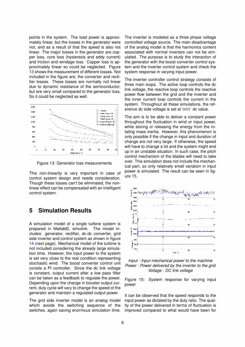
points in the system. The load power is approxi-mately linear, but the losses in the generator werenot, and as a result of that the speed is also notlinear. The major losses in the generator are cop-per loss, core loss (hysteresis and eddy current)and friction and windage loss. Copper loss is ap-proximately linear so could be neglected. Figure13 shows the measurement of different losses. Notincluded in the figure are, the converter and recti-fier losses. These losses are normally not lineardue to dynamic resistance of the semiconductor,but are very small compared to the generator loss.So it could be neglected as well.
Figure 13: Generator loss measurements
This non-linearity is very important in case ofcontrol system design and needs consideration.Though these losses can’t be eliminated, the non-linear effect can be compensated with an intelligentcontrol system.
5 Simulation Results
A simulation model of a single turbine system isprepared in Matlab©, simulink. The model in-cludes: generator, rectifier, dc-dc converter, gridside inverter and control system as shown in figure14 (next page). Mechanical model of the turbine isnot included considering the already large simula-tion time. However, the input power to the systemis set very close to the real condition representingstochastic wind. The boost converter control unitconsits a PI controller. Since the dc link voltageis constant, output current after a low pass filtercan be taken as a feedback to regulate the power.Depending upon the change in booster output cur-rent, duty cycle will vary to change the speed of thegenerator and maintain a regulated output power.
The grid side inverter model is an analog modelwhich avoids the switching sequence of theswitches, again saving enormous simulation time.
The inverter is modeled as a three phase voltagecontrolled voltage source. The main disadvantageof the analog model is that the harmonics contentassociated with normal inverters can not be sim-ulated. The purpose is to study the interaction ofthe generator with the boost converter control sys-tem and the inverter control system and check thesystem response in varying input power.
The inverter controller control strategy consists ofthree main loops. The active loop controls the dclink voltage, the reactive loop controls the reactivepower flow between the grid and the inverter andthe inner current loop controls the current in thesystem. Throughout all these simulations, the ref-erence dc side voltage is set at 500V dc value.
The aim is to be able to deliver a constant powerthroughout the fluctuation in wind or input power,while storing or releasing the energy from the ro-tating mass inertia. However, this phenomenon isonly possible if the change in input and duration ofchange are not very large. If otherwise, the speedwill have to change a lot and the system might endup in an unstable situation. In such case, the pitchcontrol mechanism of the blades will need to takeover. This simulation does not include the mechan-ical part, so only relatively small variation in inputpower is simulated. The result can be seen in fig-ure 15.
Input : Input mechanical power to the machinePower : Power delivered by the inverter to the grid
Voltage : DC link voltage
Figure 15: System response for varying inputpower
It can be observed that the speed responds to theinput power as dictated by the duty ratio. The qual-ity of the power delivered in terms of fluctuation isimproved compared to what would have been for
6
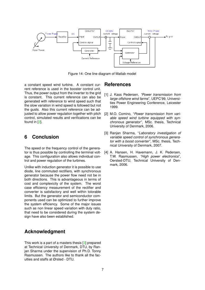
Figure 14: One line diagram of Matlab model
a constant speed wind turbine. A constant cur-rent reference is used in the booster control unit.Thus, the power output from the inverter to the gridis constant. This current reference can also begenerated with reference to wind speed such thatthe slow variation in wind speed is followed but notthe gusts. Also this current reference can be ad-justed to allow power regulation together with pitchcontrol, simulated results and verifications can befound in [2].
6 Conclusion
The speed or the frequency control of the genera-tor is thus possible by controlling the terminal volt-age. This configuration also allows individual con-trol and power regulation of the turbines.
Unlike with induction generator it is possible to usediode, line commuted rectifiers, with synchronousgenerator because the power flow need not be inboth directions. This is advantageous in terms ofcost and complexicity of the system. The worstcase efficiency measurement of the rectifier andconverter is satisfactory and well within tolorablelimits. But the generator and semiconductor com-ponents used can be optimized to further improvethe system efficiency. Some of the major issuessuch as non linear speed variation with duty ratio,that need to be considered during the system de-sign have also been established.
Acknowledgment
This work is a part of a masters thesis [3] preparedat Technical University of Denmark, DTU, by Ran-jan Sharma under the supervision of Ph.D. TonnyRasmussen. The authors like to thank all the fac-ulties and staffs at Ørsted - DTU.
References
[1] J. Kass Pedersen, “Power transmission fromlarge offshore wind farms”, UEPC’99, Universi-ties Power Engineering Conference, Leicester1999.
[2] M.O. Comino, “Power transmission from vari-able speed wind turbine equipped with syn-chronous generator ”, MSc. thesis, TechnicalUniversity of Denmark, 2006.
[3] Ranjan Sharma, “Laboratory investigation ofvariable speed control of synchronous genera-tor with a boost converter ”, MSc. thesis, Tech-nical University of Denmark, 2007.
[4] A. Hansen, H. Havemann, J. K. Pedersen,T.W. Rasmussen, “High power electronics”,Oersted-DTU, Technical University of Den-mark, 2006.
7