lab5-1_hsrp
TRANSCRIPT

CCNPv6 SWITCH
Chapter 5 Lab 5-1, Hot Standby Router Protocol
Topology
Objective Configure inter-VLAN routing with HSRP to provide redundant, fault-tolerant routing to the internal
network.
Background Hot Standby Router Protocol (HSRP) is a Cisco-proprietary redundancy protocol for establishing a fault-tolerant default gateway. It is described in RFC 2281. HSRP provides a transparent failover mechanism to the end stations on the network. This provides users at the access layer with uninterrupted service to the network if the primary gateway becomes inaccessible. The Virtual Router Redundancy Protocol (VRRP) is a standards-based alternative to HSRP and is defined in RFC 3768. The two technologies are similar but not compatible. This lab focuses on HSRP.
Note: This lab uses Cisco WS-C2960-24TT-L switches with the Cisco IOS image c2960-lanbasek9-mz.122-46.SE.bin, and Catalyst 3560-24PS with the Cisco IOS image c3560-advipservicesk9-mz.122-46.SE.bin. You can use other switches (such as 2950 or 3550) and Cisco IOS Software versions if they have comparable capabilities and features. Depending on the switch model and Cisco IOS Software version, the commands available and output produced might vary from what is shown in this lab.
All contents are Copyright © 1992–2010 Cisco Systems, Inc. All rights reserved. This document is Cisco Public Information. Page 1 of 19

CCNPv6 SWITCH
Required Resources 2 switches (Cisco 2960 with the Cisco IOS Release 12.2(46)SE C2960-LANBASEK9-M image or
comparable) 2 switches (Cisco 3560 with the Cisco IOS Release 12.2(46)SE C3560-ADVIPSERVICESK9-mz
image or comparable) Ethernet and console cables
Step 1: Prepare the switches for the lab.Erase the startup config, delete the vlan.dat file, and reload the switches. Refer to Lab 1-1, “Clearing a Switch” and Lab 1-2, “Clearing a Switch Connected to a Larger Network” to prepare the switches for this lab. Cable the equipment as shown.
Step 2: Configure the host IP settings.Configure each host with the IP address, subnet mask, and default gateway shown in the topology.
Step 3: Configure basic switch parameters.a. Configure management IP addresses in VLAN 1, and the hostname, password, and Telnet access on all
four switches.
Switch(config)# hostname ALS1ALS1(config)# enable secret ciscoALS1(config)# line vty 0 15ALS1(config-line)# password ciscoALS1(config-line)# loginALS1(config-line)# exitALS1(config)# interface vlan 1ALS1(config-if)# ip address 172.16.1.101 255.255.255.0ALS1(config-if)# no shutdown
Switch(config)# hostname ALS2ALS2(config)# enable secret ciscoALS2(config)# line vty 0 15ALS2(config-line)# password ciscoALS2(config-line)# loginALS2(config-line)# exitALS2(config)# interface vlan 1ALS2(config-if)# ip address 172.16.1.102 255.255.255.0ALS2(config-if)# no shutdown
Switch(config)# hostname DLS1DLS1(config)# enable secret ciscoDLS1(config)# line vty 0 15DLS1(config-line)# password ciscoDLS1(config-line)# loginDLS1(config-line)# exitDLS1(config)# interface vlan 1DLS1(config-if)# ip address 172.16.1.3 255.255.255.0DLS1(config-if)# no shutdown
Switch(config)# hostname DLS2DLS2(config)# enable secret ciscoDLS2(config)# line vty 0 15DLS2(config-line)# password cisco
All contents are Copyright © 1992–2010 Cisco Systems, Inc. All rights reserved. This document is Cisco Public Information. Page 2 of 19

CCNPv6 SWITCH
DLS2(config-line)# loginDLS2(config-line)# exitDLS2(config)# interface vlan 1DLS2(config-if)# ip address 172.16.1.4 255.255.255.0DLS2(config-if)# no shutdown
b. Configure default gateways on the access layer switches ALS1 and ALS2. The distribution layer switches will not use a default gateway because they act as Layer 3 devices. The access layer switches act as Layer 2 devices and need a default gateway to send management VLAN traffic off of the local subnet for the management VLAN.
ALS1(config)# ip default-gateway 172.16.1.1
ALS2(config)# ip default-gateway 172.16.1.1
Step 4: Configure trunks and EtherChannels between switches.EtherChannel is used for the trunks because it allows you to utilize both Fast Ethernet interfaces that are available between each device, thereby doubling the bandwidth.
Note: It is good practice to shut down the interfaces on both sides of the link before a port channel is created and then reenable them after the port channel is configured.
a. Configure trunks and EtherChannels from DLS1 and DLS2 to the other three switches according to the diagram. The switchport trunk encapsulation {isl | dot1q} command is used because these switches also support ISL encapsulation.
DLS1(config)# interface range fastEthernet 0/7 - 8DLS1(config-if-range)# switchport trunk encapsulation dot1qDLS1(config-if-range)# switchport mode trunkDLS1(config-if-range)# channel-group 1 mode desirable
Creating a port-channel interface Port-channel 1
DLS1(config-if-range)# interface range fastEthernet 0/9 - 10DLS1(config-if-range)# switchport trunk encapsulation dot1qDLS1(config-if-range)# switchport mode trunkDLS1(config-if-range)# channel-group 2 mode desirable
Creating a port-channel interface Port-channel 2
DLS1(config-if-range)# interface range fastEthernet 0/11 - 12DLS1(config-if-range)# switchport trunk encapsulation dot1qDLS1(config-if-range)# switchport mode trunkDLS1(config-if-range)# channel-group 3 mode desirable
Creating a port-channel interface Port-channel 3
DLS2(config)# interface range fastEthernet 0/7 - 8DLS2(config-if-range)# switchport trunk encapsulation dot1qDLS2(config-if-range)# switchport mode trunkDLS2(config-if-range)# channel-group 1 mode desirable
Creating a port-channel interface Port-channel 1
DLS2(config-if-range)# interface range fastEthernet 0/9 - 10DLS2(config-if-range)# switchport trunk encapsulation dot1qDLS2(config-if-range)# switchport mode trunkDLS2(config-if-range)# channel-group 2 mode desirable
All contents are Copyright © 1992–2010 Cisco Systems, Inc. All rights reserved. This document is Cisco Public Information. Page 3 of 19

CCNPv6 SWITCH
Creating a port-channel interface Port-channel 2
DLS2(config-if-range)# interface range fastEthernet 0/11 - 12DLS2(config-if-range)# switchport trunk encapsulation dot1qDLS2(config-if-range)# switchport mode trunkDLS2(config-if-range)# channel-group 3 mode desirable
Creating a port-channel interface Port-channel 3
b. Configure the trunks and EtherChannel from ALS1 and ALS2 to the other switches. Notice that no encapsulation type is needed because the 2960 supports only 802.1q trunks.
ALS1(config)# interface range fastEthernet 0/7 - 8ALS1(config-if-range)# switchport mode trunkALS1(config-if-range)# channel-group 1 mode desirable
Creating a port-channel interface Port-channel 1
ALS1(config-if-range)# interface range fastEthernet 0/9 - 10ALS1(config-if-range)# switchport mode trunkALS1(config-if-range)# channel-group 2 mode desirable
Creating a port-channel interface Port-channel 2
ALS1(config-if-range)# interface range fastEthernet 0/11 - 12ALS1(config-if-range)# switchport mode trunkALS1(config-if-range)# channel-group 3 mode desirable
Creating a port-channel interface Port-channel 3
ALS2(config)# interface range fastEthernet 0/7 - 8ALS2(config-if-range)# switchport mode trunkALS2(config-if-range)# channel-group 1 mode desirable
Creating a port-channel interface Port-channel 1
ALS2(config-if-range)# interface range fastEthernet 0/9 - 10ALS2(config-if-range)# switchport mode trunkALS2(config-if-range)# channel-group 2 mode desirable
Creating a port-channel interface Port-channel 2
ALS2(config-if-range)# interface range fastEthernet 0/11 - 12ALS2(config-if-range)# switchport mode trunkALS2(config-if-range)# channel-group 3 mode desirable
Creating a port-channel interface Port-channel 3
c. Verify trunking between DLS1, ALS1, and ALS2 using the show interface trunk command on all switches.
DLS1# show interface trunk
Port Mode Encapsulation Status Native vlanPo1 on 802.1q trunking 1Po2 on 802.1q trunking 1Po3 on 802.1q trunking 1
All contents are Copyright © 1992–2010 Cisco Systems, Inc. All rights reserved. This document is Cisco Public Information. Page 4 of 19

CCNPv6 SWITCH
Port Vlans allowed on trunkPo1 1-4094Po2 1-4094Po3 1-4094
Port Vlans allowed and active in management domainPo1 1Po2 1Po3 1
Port Vlans in spanning tree forwarding state and not prunedPo1 1Po2 1Po3 1
d. Issue the show etherchannel summary command on each switch to verify the EtherChannels. In the following sample output from ALS1, notice the three EtherChannels on the access and distribution layer switches.
ALS1# show etherchannel summary Flags: D - down P - in port-channel I - stand-alone s - suspended H - Hot-standby (LACP only) R - Layer3 S - Layer2 U - in use f - failed to allocate aggregator u - unsuitable for bundling w - waiting to be aggregated d - default port
Number of channel-groups in use: 3Number of aggregators: 3
Group Port-channel Protocol Ports------+-------------+-----------+--------------------------------------------1 Po1(SU) PAgP Fa0/7(P) Fa0/8(P) 2 Po2(SU) PAgP Fa0/9(P) Fa0/10(P) 3 Po3(SU) PAgP Fa0/11(P) Fa0/12(P)
Which EtherChannel negotiation protocol is in use here?
________________________________________________________________________________
The EtherChannel negotiation protocol in use is PAgP.
Step 5: Configure VTP on ALS1 and ALS2.a. Change the VTP mode of ALS1 and ALS2 to client.
ALS1(config)# vtp mode clientSetting device to VTP CLIENT mode.
ALS2(config)# vtp mode clientSetting device to VTP CLIENT mode.
b. Verify the VTP changes with the show vtp status command.
ALS1# show vtp statusVTP Version : running VTP1 (VTP2 capable)Configuration Revision : 0Maximum VLANs supported locally : 255
All contents are Copyright © 1992–2010 Cisco Systems, Inc. All rights reserved. This document is Cisco Public Information. Page 5 of 19

CCNPv6 SWITCH
Number of existing VLANs : 5VTP Operating Mode : ClientVTP Domain Name : VTP Pruning Mode : DisabledVTP V2 Mode : DisabledVTP Traps Generation : DisabledMD5 digest : 0xC8 0xAB 0x3C 0x3B 0xAB 0xDD 0x34 0xCF Configuration last modified by 0.0.0.0 at 3-1-93 15:47:34
How many VLANs can be supported locally on the 2960 switch?
________________________________________________________________________________
This switch and Cisco IOS Software version can support 255 VLANs.
Step 6: Configure VTP on DLS1.a. Create the VTP domain on VTP server DLS1 and create VLANs 10, 20, 30, and 40 for the domain.
DLS1(config)# vtp domain SWPODDLS1(config)# vtp version 2
DLS1(config)# vlan 10DLS1(config-vlan)# name FinanceDLS1(config-vlan)# vlan 20 DLS1(config-vlan)# name EngineeringDLS1(config-vlan)# vlan 30DLS1(config-vlan)# name Server-Farm1DLS1(config-vlan)# vlan 40DLS1(config-vlan)# name Server-Farm2
b. Verify VTP information throughout the domain using the show vlan and show vtp status commands.
How many existing VLANs are in the VTP domain?
________________________________________________________________________________
There should be nine VLANs: the five built-in ones, plus the four new VLANs that you just created.
Step 7: Configure access ports.a. Configure the host ports of all four switches. The following commands configure the switch port mode as
access, place the port in the proper VLANs, and turn on spanning-tree PortFast for the ports.
DLS1(config)# interface fastEthernet 0/6DLS1(config-if)# switchport mode accessDLS1(config-if)# switchport access vlan 30DLS1(config-if)# spanning-tree portfast
DLS2(config)# interface fastEthernet 0/6DLS2(config-if)# switchport mode accessDLS2(config-if)# switchport access vlan 40DLS2(config-if)# spanning-tree portfast
ALS1(config)# interface fastEthernet 0/6ALS1(config-if)# switchport mode accessALS1(config-if)# switchport access vlan 10ALS1(config-if)# spanning-tree portfast
ALS2(config)# interface fastEthernet 0/6ALS2(config-if)# switchport mode access
All contents are Copyright © 1992–2010 Cisco Systems, Inc. All rights reserved. This document is Cisco Public Information. Page 6 of 19

CCNPv6 SWITCH
ALS2(config-if)# switchport access vlan 20ALS2(config-if)# spanning-tree portfast
b. Ping from the host on VLAN 10 to the host on VLAN 40. The ping should fail.
Are these results expected at this point? Why?
________________________________________________________________________________
________________________________________________________________________________
________________________________________________________________________________
Yes, it is expected that the pings will fail because no SVIs have been created on DLS1 and DLS2, except for VLAN 1. Therefore, there is no default gateway for the hosts.
Note: The switchport host command can be used to configure individual access ports. This command automatically activates access mode, PortFast, and removes all associations of the physical switch port with the port-channel interfaces (if there are any).
Step 8: Configure HSRP interfaces and enable routing.HSRP provides redundancy in the network. The VLANs can be load-balanced by using the standby group priority priority command. The ip routing command is used on DLS1 and DLS2 to activate routing capabilities on these Layer 3 switches.
Each route processor can route between the various SVIs configured on its switch. In addition to the real IP address assigned to each distribution switch SVI, assign a third IP address in each subnet to be used as a virtual gateway address. HSRP negotiates and determines which switch accepts information forwarded to the virtual gateway IP address.
The standby command configures the IP address of the virtual gateway, sets the priority for each VLAN, and configures the router for preempt. Preemption allows the router with the higher priority to become the active router after a network failure has been resolved.
In the following configurations, the priority for VLANs 1, 10, and 20 is 150 on DLS1, making it the active router for those VLANs. VLANs 30 and 40 have a priority of 100 on DLS1, making DLS1 the standby router for these VLANs. DLS2 is configured to be the active router for VLANs 30 and 40 with a priority of 150, and the standby router for VLANs 1, 10, and 20 with a priority of 100.
DLS1(config)# ip routing
DLS1(config)# interface vlan 1DLS1(config-if)# standby 1 ip 172.16.1.1DLS1(config-if)# standby 1 preemptDLS1(config-if)# standby 1 priority 150DLS1(config-if)# exit
DLS1(config)# interface vlan 10DLS1(config-if)# ip address 172.16.10.3 255.255.255.0DLS1(config-if)# standby 1 ip 172.16.10.1DLS1(config-if)# standby 1 preemptDLS1(config-if)# standby 1 priority 150DLS1(config-if)# exit
DLS1(config)# interface vlan 20DLS1(config-if)# ip address 172.16.20.3 255.255.255.0DLS1(config-if)# standby 1 ip 172.16.20.1DLS1(config-if)# standby 1 preemptDLS1(config-if)# standby 1 priority 150
All contents are Copyright © 1992–2010 Cisco Systems, Inc. All rights reserved. This document is Cisco Public Information. Page 7 of 19

CCNPv6 SWITCH
DLS1(config-if)# exit
DLS1(config)# interface vlan 30DLS1(config-if)# ip address 172.16.30.3 255.255.255.0DLS1(config-if)# standby 1 ip 172.16.30.1DLS1(config-if)# standby 1 preemptDLS1(config-if)# standby 1 priority 100DLS1(config-if)# exit
DLS1(config)# interface vlan 40DLS1(config-if)# ip address 172.16.40.3 255.255.255.0DLS1(config-if)# standby 1 ip 172.16.40.1DLS1(config-if)# standby 1 preemptDLS1(config-if)# standby 1 priority 100
DLS2(config)# ip routing
DLS2(config)# interface vlan 1DLS2(config-if)# standby 1 ip 172.16.1.1DLS2(config-if)# standby 1 preemptDLS2(config-if)# standby 1 priority 100DLS2(config-if)# exit
DLS2(config)# interface vlan 10DLS2(config-if)# ip address 172.16.10.4 255.255.255.0DLS2(config-if)# standby 1 ip 172.16.10.1DLS2(config-if)# standby 1 preemptDLS2(config-if)# standby 1 priority 100DLS2(config-if)# exit
DLS2(config)# interface vlan 20DLS2(config-if)# ip address 172.16.20.4 255.255.255.0DLS2(config-if)# standby 1 ip 172.16.20.1DLS2(config-if)# standby 1 preemptDLS2(config-if)# standby 1 priority 100DLS2(config-if)# exit
DLS2(config)# interface vlan 30DLS2(config-if)# ip address 172.16.30.4 255.255.255.0DLS2(config-if)# standby 1 ip 172.16.30.1DLS2(config-if)# standby 1 preemptDLS2(config-if)# standby 1 priority 150DLS2(config-if)# exit
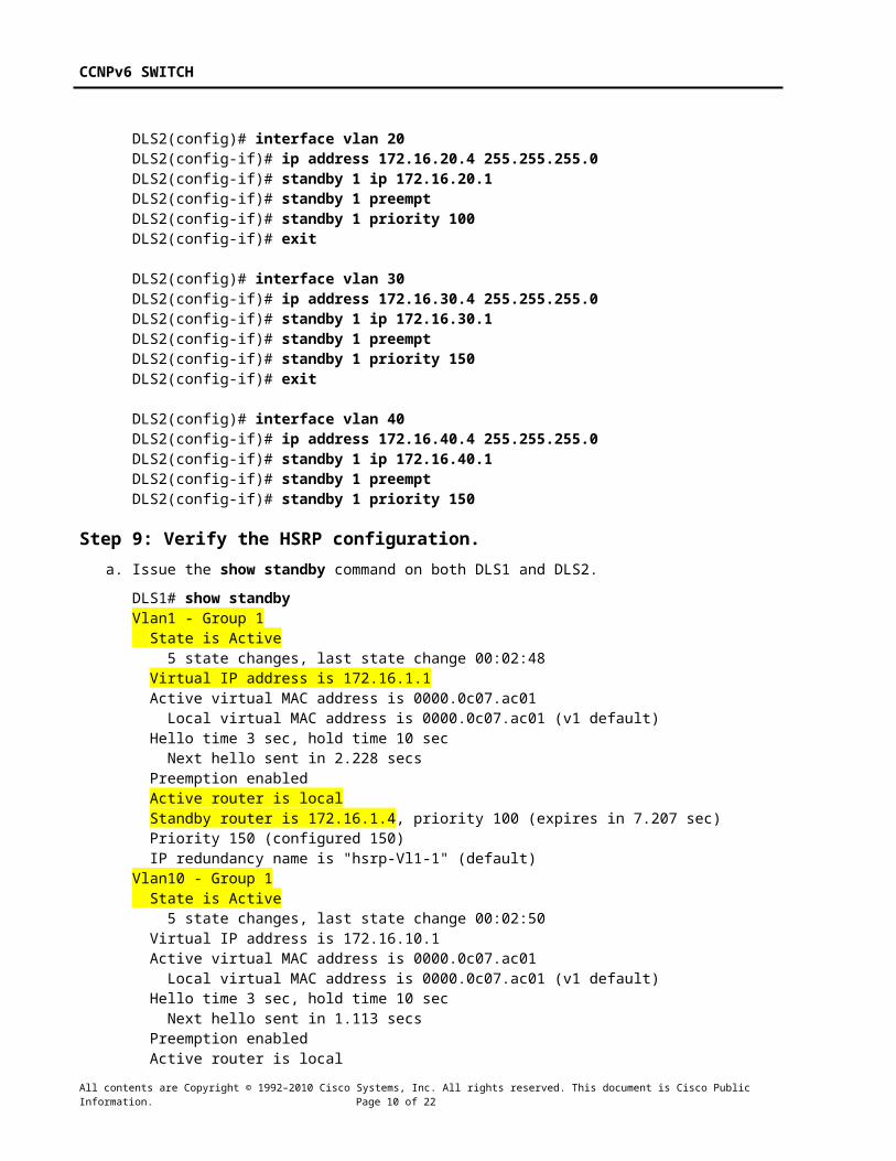
DLS2(config)# interface vlan 40DLS2(config-if)# ip address 172.16.40.4 255.255.255.0DLS2(config-if)# standby 1 ip 172.16.40.1DLS2(config-if)# standby 1 preemptDLS2(config-if)# standby 1 priority 150
Step 9: Verify the HSRP configuration.a. Issue the show standby command on both DLS1 and DLS2.
DLS1# show standbyVlan1 - Group 1 State is Active
All contents are Copyright © 1992–2010 Cisco Systems, Inc. All rights reserved. This document is Cisco Public Information. Page 8 of 19

CCNPv6 SWITCH
5 state changes, last state change 00:02:48 Virtual IP address is 172.16.1.1 Active virtual MAC address is 0000.0c07.ac01 Local virtual MAC address is 0000.0c07.ac01 (v1 default) Hello time 3 sec, hold time 10 sec Next hello sent in 2.228 secs Preemption enabled Active router is local Standby router is 172.16.1.4, priority 100 (expires in 7.207 sec) Priority 150 (configured 150) IP redundancy name is "hsrp-Vl1-1" (default)Vlan10 - Group 1 State is Active 5 state changes, last state change 00:02:50 Virtual IP address is 172.16.10.1 Active virtual MAC address is 0000.0c07.ac01 Local virtual MAC address is 0000.0c07.ac01 (v1 default) Hello time 3 sec, hold time 10 sec Next hello sent in 1.113 secs Preemption enabled Active router is local Standby router is 172.16.10.4, priority 100 (expires in 9.807 sec) Priority 150 (configured 150) IP redundancy name is "hsrp-Vl10-1" (default)Vlan20 - Group 1 State is Active 5 state changes, last state change 00:02:55 Virtual IP address is 172.16.20.1 Active virtual MAC address is 0000.0c07.ac01 Local virtual MAC address is 0000.0c07.ac01 (v1 default) Hello time 3 sec, hold time 10 sec Next hello sent in 1.884 secs Preemption enabled Active router is local Standby router is 172.16.20.4, priority 100 (expires in 9.220 sec) Priority 150 (configured 150) IP redundancy name is "hsrp-Vl20-1" (default)Vlan30 - Group 1 State is Standby 4 state changes, last state change 00:02:45 Virtual IP address is 172.16.30.1 Active virtual MAC address is 0000.0c07.ac01 Local virtual MAC address is 0000.0c07.ac01 (v1 default) Hello time 3 sec, hold time 10 sec Next hello sent in 2.413 secs Preemption enabled Active router is 172.16.30.4, priority 150 (expires in 8.415 sec) Standby router is local Priority 100 (default 100) IP redundancy name is "hsrp-Vl30-1" (default)Vlan40 - Group 1 State is Standby 4 state changes, last state change 00:02:51 Virtual IP address is 172.16.40.1 Active virtual MAC address is 0000.0c07.ac01 Local virtual MAC address is 0000.0c07.ac01 (v1 default) Hello time 3 sec, hold time 10 sec Next hello sent in 1.826 secs
All contents are Copyright © 1992–2010 Cisco Systems, Inc. All rights reserved. This document is Cisco Public Information. Page 9 of 19
CCNPv6 SWITCH
Preemption enabled Active router is 172.16.40.4, priority 150 (expires in 7.828 sec) Standby router is local Priority 100 (default 100) IP redundancy name is "hsrp-Vl40-1" (default)
DLS2# show standbyVlan1 - Group 1 State is Standby 3 state changes, last state change 00:02:33 Virtual IP address is 172.16.1.1 Active virtual MAC address is 0000.0c07.ac01 Local virtual MAC address is 0000.0c07.ac01 (v1 default) Hello time 3 sec, hold time 10 sec Next hello sent in 2.950 secs Preemption enabled Active router is 172.16.1.3, priority 150 (expires in 8.960 sec) Standby router is local Priority 100 (default 100) IP redundancy name is "hsrp-Vl1-1" (default)Vlan10 - Group 1 State is Standby 3 state changes, last state change 00:02:34 Virtual IP address is 172.16.10.1 Active virtual MAC address is 0000.0c07.ac01 Local virtual MAC address is 0000.0c07.ac01 (v1 default) Hello time 3 sec, hold time 10 sec Next hello sent in 1.759 secs Preemption enabled Active router is 172.16.10.3, priority 150 (expires in 7.844 sec) Standby router is local Priority 100 (default 100) IP redundancy name is "hsrp-Vl10-1" (default)Vlan20 - Group 1 State is Standby 3 state changes, last state change 00:02:42 Virtual IP address is 172.16.20.1 Active virtual MAC address is 0000.0c07.ac01 Local virtual MAC address is 0000.0c07.ac01 (v1 default) Hello time 3 sec, hold time 10 sec Next hello sent in 2.790 secs Preemption enabled Active router is 172.16.20.3, priority 150 (expires in 8.289 sec) Standby router is local Priority 100 (default 100) IP redundancy name is "hsrp-Vl20-1" (default)Vlan30 - Group 1 State is Active 2 state changes, last state change 00:02:52 Virtual IP address is 172.16.30.1 Active virtual MAC address is 0000.0c07.ac01 Local virtual MAC address is 0000.0c07.ac01 (v1 default) Hello time 3 sec, hold time 10 sec Next hello sent in 1.549 secs Preemption enabled Active router is local Standby router is 172.16.30.3, priority 100 (expires in 9.538 sec) Priority 150 (configured 150)
All contents are Copyright © 1992–2010 Cisco Systems, Inc. All rights reserved. This document is Cisco Public Information. Page 10 of 19

CCNPv6 SWITCH
IP redundancy name is "hsrp-Vl30-1" (default)Vlan40 - Group 1 State is Active 2 state changes, last state change 00:02:58 Virtual IP address is 172.16.40.1 Active virtual MAC address is 0000.0c07.ac01 Local virtual MAC address is 0000.0c07.ac01 (v1 default) Hello time 3 sec, hold time 10 sec Next hello sent in 0.962 secs Preemption enabled Active router is local Standby router is 172.16.40.3, priority 100 (expires in 8.960 sec) Priority 150 (configured 150) IP redundancy name is "hsrp-Vl40-1" (default)
b. Issue the show standby brief command on both DLS1 and DLS2.
DLS1# show standby brief P indicates configured to preempt. |Interface Grp Pri P State Active Standby Virtual IPVl1 1 150 P Active local 172.16.1.4 172.16.1.1Vl10 1 150 P Active local 172.16.10.4 172.16.10.1Vl20 1 150 P Active local 172.16.20.4 172.16.20.1Vl30 1 100 P Standby 172.16.30.4 local 172.16.30.1Vl40 1 100 P Standby 172.16.40.4 local 172.16.40.1
DLS2# show standby brief P indicates configured to preempt. |Interface Grp Pri P State Active Standby Virtual IPVl1 1 100 P Standby 172.16.1.3 local 172.16.1.1Vl10 1 100 P Standby 172.16.10.3 local 172.16.10.1Vl20 1 100 P Standby 172.16.20.3 local 172.16.20.1Vl30 1 150 P Active local 172.16.30.3 172.16.30.1Vl40 1 150 P Active local 172.16.40.3 172.16.40.1
Which router is the active router for VLANs 1, 10, and 20? Which is the active router for 30 and 40?
________________________________________________________________________________
For VLANs 1, 10, and 20, the active router is DLS1. For VLANs 30 and 40, the active router is DLS2.
What is the default hello time for each VLAN? What is the default hold time?
________________________________________________________________________________
The default hello time is 3 seconds. The default hold time is 10 seconds.
How is the active HSRP router selected?
________________________________________________________________________________
The router with the highest priority is selected as the active HSRP router. If more routers share the highest priority, the HSRP router with the highest IP address on the segment becomes the active router.
c. Use the show ip route command to verify routing on both DLS1 and DLS2.
DLS1# show ip routeCodes: C - connected, S - static, R - RIP, M - mobile, B - BGP D - EIGRP, EX - EIGRP external, O - OSPF, IA - OSPF inter area N1 - OSPF NSSA external type 1, N2 - OSPF NSSA external type 2
All contents are Copyright © 1992–2010 Cisco Systems, Inc. All rights reserved. This document is Cisco Public Information. Page 11 of 19

CCNPv6 SWITCH
E1 - OSPF external type 1, E2 - OSPF external type 2, E - EGP i - IS-IS, su - IS-IS summary, L1 - IS-IS level-1, L2 - IS-IS level-2 ia - IS-IS inter area, * - candidate default, U - per-user static route o - ODR, P - periodic downloaded static route
Gateway of last resort is not set
172.16.0.0/24 is subnetted, 5 subnetsC 172.16.40.0 is directly connected, Vlan40C 172.16.30.0 is directly connected, Vlan30C 172.16.20.0 is directly connected, Vlan20C 172.16.10.0 is directly connected, Vlan10C 172.16.1.0 is directly connected, Vlan1
Step 10: Verify connectivity between VLANs.Verify connectivity between VLANs using the ping command from the SQL Server (VLAN 40) to the other hosts and servers on the network.
The following is from the SQL Server (VLAN 40) to the Engineering host (VLAN 20):
C:\> ping 172.16.20.100
Pinging 172.16.20.100 with 32 bytes of data:
Reply from 172.16.20.100: bytes=32 time=2ms TTL=255Reply from 172.16.20.100: bytes=32 time=2ms TTL=255Reply from 172.16.20.100: bytes=32 time=2ms TTL=255Reply from 172.16.20.100: bytes=32 time=2ms TTL=255
Ping statistics for 172.16.20.100: Packets: Sent = 4, Received = 4, Lost = 0 (0% loss),Approximate round trip times in milli-seconds: Minimum = 2ms, Maximum = 2ms, Average = 2ms
Step 11: Verify HSRP functionally.a. Verify HSRP by disconnecting the trunks to DLS2. You can simulate this using the shutdown command
on those interfaces.
DLS2(config)# interface range fastEthernet 0/7 - 12DLS2(config-if-range)# shutdown
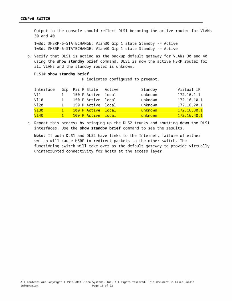
Output to the console should reflect DLS1 becoming the active router for VLANs 30 and 40.
1w3d: %HSRP-6-STATECHANGE: Vlan30 Grp 1 state Standby -> Active1w3d: %HSRP-6-STATECHANGE: Vlan40 Grp 1 state Standby -> Active
b. Verify that DLS1 is acting as the backup default gateway for VLANs 30 and 40 using the show standby brief command. DLS1 is now the active HSRP router for all VLANs and the standby router is unknown.
DLS1# show standby brief P indicates configured to preempt. |Interface Grp Pri P State Active Standby Virtual IPVl1 1 150 P Active local unknown 172.16.1.1Vl10 1 150 P Active local unknown 172.16.10.1Vl20 1 150 P Active local unknown 172.16.20.1Vl30 1 100 P Active local unknown 172.16.30.1Vl40 1 100 P Active local unknown 172.16.40.1
All contents are Copyright © 1992–2010 Cisco Systems, Inc. All rights reserved. This document is Cisco Public Information. Page 12 of 19

CCNPv6 SWITCH
c. Repeat this process by bringing up the DLS2 trunks and shutting down the DLS1 interfaces. Use the show standby brief command to see the results.
Note: If both DLS1 and DLS2 have links to the Internet, failure of either switch will cause HSRP to redirect packets to the other switch. The functioning switch will take over as the default gateway to provide virtually uninterrupted connectivity for hosts at the access layer.
All contents are Copyright © 1992–2010 Cisco Systems, Inc. All rights reserved. This document is Cisco Public Information. Page 13 of 19

CCNPv6 SWITCH
Device Configurations Note: VTP and VLAN commands do not display in the running configuration, unless the switch is in transparent mode. DLS1 and DLS2 are VTP servers, and ALS1 and ALS2 are VTP clients. Refer to the appropriate steps in the lab for the necessary VTP and VLAN configuration commands.
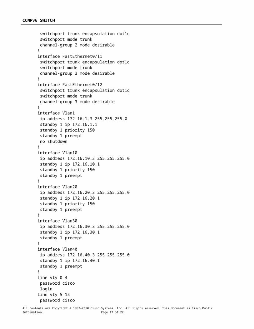
Switch DLS1 hostname DLS1!enable secret cisco!ip routing!interface Port-channel1 switchport trunk encapsulation dot1q switchport mode trunk!interface Port-channel2 switchport trunk encapsulation dot1q switchport mode trunk!interface Port-channel3 switchport trunk encapsulation dot1q switchport mode trunk!interface FastEthernet0/6 switchport access vlan 30 switchport mode access spanning-tree portfast!interface FastEthernet0/7 switchport trunk encapsulation dot1q switchport mode trunk channel-group 1 mode desirable!interface FastEthernet0/8 switchport trunk encapsulation dot1q switchport mode trunk channel-group 1 mode desirable!interface FastEthernet0/9 switchport trunk encapsulation dot1q switchport mode trunk channel-group 2 mode desirable!interface FastEthernet0/10 switchport trunk encapsulation dot1q switchport mode trunk channel-group 2 mode desirable!interface FastEthernet0/11 switchport trunk encapsulation dot1q switchport mode trunk channel-group 3 mode desirable!interface FastEthernet0/12
All contents are Copyright © 1992–2010 Cisco Systems, Inc. All rights reserved. This document is Cisco Public Information. Page 14 of 19
CCNPv6 SWITCH
switchport trunk encapsulation dot1q switchport mode trunk channel-group 3 mode desirable!interface Vlan1 ip address 172.16.1.3 255.255.255.0 standby 1 ip 172.16.1.1 standby 1 priority 150 standby 1 preempt no shutdown!interface Vlan10 ip address 172.16.10.3 255.255.255.0 standby 1 ip 172.16.10.1 standby 1 priority 150 standby 1 preempt!interface Vlan20 ip address 172.16.20.3 255.255.255.0 standby 1 ip 172.16.20.1 standby 1 priority 150 standby 1 preempt!interface Vlan30 ip address 172.16.30.3 255.255.255.0 standby 1 ip 172.16.30.1 standby 1 preempt!interface Vlan40 ip address 172.16.40.3 255.255.255.0 standby 1 ip 172.16.40.1 standby 1 preempt!line vty 0 4 password cisco loginline vty 5 15 password cisco login!end
Switch DLS2hostname DLS2!enable secret cisco!ip routing!interface Port-channel1 switchport trunk encapsulation dot1q switchport mode trunk!interface Port-channel2 switchport trunk encapsulation dot1q switchport mode trunk
All contents are Copyright © 1992–2010 Cisco Systems, Inc. All rights reserved. This document is Cisco Public Information. Page 15 of 19

CCNPv6 SWITCH
!interface Port-channel3 switchport trunk encapsulation dot1q switchport mode trunk!interface FastEthernet0/6 switchport access vlan 40 switchport mode access spanning-tree portfast!interface FastEthernet0/7 switchport trunk encapsulation dot1q switchport mode trunk channel-group 1 mode desirable!interface FastEthernet0/8 switchport trunk encapsulation dot1q switchport mode trunk channel-group 1 mode desirable!interface FastEthernet0/9 switchport trunk encapsulation dot1q switchport mode trunk channel-group 2 mode desirable!interface FastEthernet0/10 switchport trunk encapsulation dot1q switchport mode trunk channel-group 2 mode desirable!interface FastEthernet0/11 switchport trunk encapsulation dot1q switchport mode trunk channel-group 3 mode desirable!interface FastEthernet0/12 switchport trunk encapsulation dot1q switchport mode trunk channel-group 3 mode desirable!interface Vlan1 ip address 172.16.1.4 255.255.255.0 standby 1 ip 172.16.1.1 standby 1 preempt no shutdown!interface Vlan10 ip address 172.16.10.4 255.255.255.0 standby 1 ip 172.16.10.1 standby 1 preempt!interface Vlan20 ip address 172.16.20.4 255.255.255.0 standby 1 ip 172.16.20.1 standby 1 preempt!interface Vlan30 ip address 172.16.30.4 255.255.255.0
All contents are Copyright © 1992–2010 Cisco Systems, Inc. All rights reserved. This document is Cisco Public Information. Page 16 of 19
CCNPv6 SWITCH
standby 1 ip 172.16.30.1 standby 1 priority 150 standby 1 preempt!interface Vlan40 ip address 172.16.40.4 255.255.255.0 standby 1 ip 172.16.40.1 standby 1 priority 150 standby 1 preempt!line vty 0 4 password cisco loginline vty 5 15 password cisco login!end
Switch ALS1 hostname ALS1!enable secret cisco!interface Port-channel1 switchport mode trunk!interface Port-channel2 switchport mode trunk!interface Port-channel3 switchport mode trunk!interface FastEthernet0/6 switchport access vlan 10 switchport mode access spanning-tree portfast!interface FastEthernet0/7 switchport mode trunk channel-group 1 mode desirable!interface FastEthernet0/8 switchport mode trunk channel-group 1 mode desirable!interface FastEthernet0/9 switchport mode trunk channel-group 2 mode desirable!interface FastEthernet0/10 switchport mode trunk channel-group 2 mode desirable!interface FastEthernet0/11 switchport mode trunk
All contents are Copyright © 1992–2010 Cisco Systems, Inc. All rights reserved. This document is Cisco Public Information. Page 17 of 19

CCNPv6 SWITCH
channel-group 3 mode desirable!interface FastEthernet0/12 switchport mode trunk channel-group 3 mode desirable!interface Vlan1 ip address 172.16.1.101 255.255.255.0 no shutdown!ip default-gateway 172.16.1.1!line vty 0 4 password cisco loginline vty 5 15 password cisco login!end
Switch ALS2 hostname ALS2!enable secret cisco!interface Port-channel1 switchport mode trunk!interface Port-channel2 switchport mode trunk!interface Port-channel3 switchport mode trunk!interface FastEthernet0/6 switchport access vlan 20 switchport mode access spanning-tree portfast!interface FastEthernet0/7 switchport mode trunk channel-group 1 mode desirable!interface FastEthernet0/8 switchport mode trunk channel-group 1 mode desirable!interface FastEthernet0/9 switchport mode trunk channel-group 2 mode desirable!interface FastEthernet0/10 switchport mode trunk channel-group 2 mode desirable!
All contents are Copyright © 1992–2010 Cisco Systems, Inc. All rights reserved. This document is Cisco Public Information. Page 18 of 19

CCNPv6 SWITCH
interface FastEthernet0/11 switchport mode trunk channel-group 3 mode desirable!interface FastEthernet0/12 switchport mode trunk channel-group 3 mode desirable!interface Vlan1 ip address 172.16.1.102 255.255.255.0 no shutdown!ip default-gateway 172.16.1.1!line vty 0 4 password cisco loginline vty 5 15 password cisco loginend
All contents are Copyright © 1992–2010 Cisco Systems, Inc. All rights reserved. This document is Cisco Public Information. Page 19 of 19