lab manual (regulation-2013) branch /section :...
TRANSCRIPT

Page 1 of 94
LAB MANUAL
(Regulation-2013)
BRANCH /SECTION : EEE
SEMESTER : IV SEM
SUBJECT CODE : EE6411
SUBJECT : Electrical Machines-1 Laboratorywww.alls
yllab
us.co
m
www.allsyllabus.com
vtu.allsyllabus.com
Page 2 of 94
EE6411 ELECTRICAL MACHINES LABORATORY – I L T P C0 0 3 2
OBJECTIVES:
To expose the students to the operation of D.C. Machines and Transformers and give
them experimental skill.
LIST OF EXPERIMENTS:
1. Open circuit and load characteristics of DC shunt generator- critical resistance and critical
speed.
2. Load characteristics of DC Compound Generator with Differential and
Cumulative connections.
3. Load test on DC Shunt and Compound Motor.
4. Load test on DC Series Motor.
5. Swinburne’s test and speed control of DC Shunt Motor.
6. Hopkinson’s test on DC Motor – Generator set.
7. Load test on Single-phase Transformer and Three phase Transformers.
8. Open circuit and short circuit tests on Single phase Transformer.
9. Polarity Test and Sumpner’s test on Single phase Transformers.
10.Separation of no-load losses in Single phase Transformer.
11.Study of Starters and 3-phase Transformers connections.
TOTAL: 45 PERIODS
OUTCOMES:
Ability to model and analyze electrical apparatus and their application to power system
www.alls
yllab
us.co
m
www.allsyllabus.com
vtu.allsyllabus.com

Page 3 of 94
EE6411– Electrical Machines-1 Laboratory
INDEX
1. Open circuit and L oad characteristics of self excited DC shunt Generator.
2. Load characteristics of DC Compound Generator with Differential and
Cumulative c o n n e c t i o n .
3. Load characteristics of DC Shunt and Compound Motor.
4. Load characteristics of DC Series Motor.
5. Swinburne’s test and speed control of DC Shunt Motor.
6. Hopkinson’s test on DC Motor–Generator set.
7. Load test on Single-phase Transformer and Three phase Transformer connections.
8. Open circuit and Short circuit tests on Single phase Transformer.
9. Polarity Test and Sumpner’s test on Single phase Transformers.
10. Separation of no-load losses in Single phase Transformer.
11. Study of starters and 3-phase Transformers connections
12. Open circuit and Load characteristics of Separately excited DC Generator.
Additional Experiments
13. Study of Three phase Induction Motor Starters.
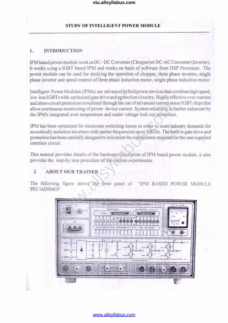
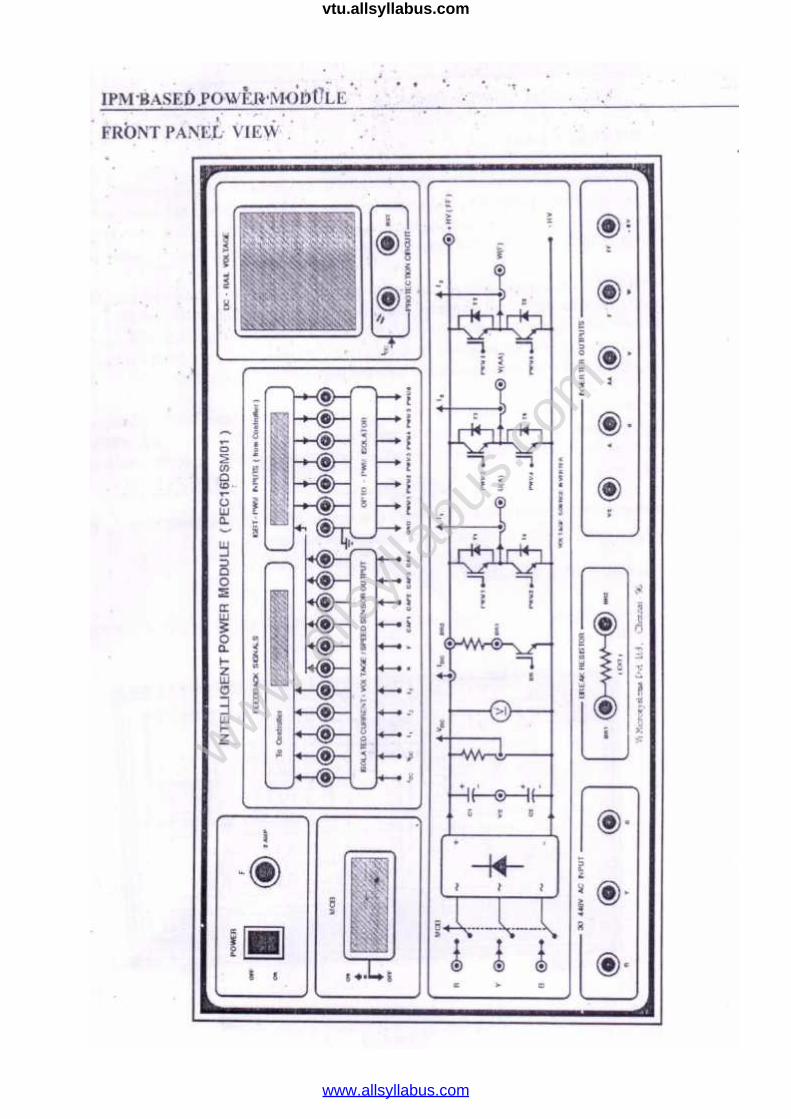
14. Study of Intelligent Power Module
www.alls
yllab
us.co
m
www.allsyllabus.com
vtu.allsyllabus.com

CYCLE-I
EXP.
NO. DATE EXPERIMENT NAME
PAGE
NO MARK SIGNATURE
1.
2.
3.
4.
5.
6.
CYCLE-II
EXP.
NO DATE EXPERIMENT NAME
PAGE
NO MARK SIGNATURE
7.
8.
9.
10.
11.
12.
13.
www.alls
yllab
us.co
m
www.allsyllabus.com
vtu.allsyllabus.com

EXP.NO.
DATE:
OPEN CIRCUIT AND LOAD CHARACTERISTICS
OF SELF EXCITED D.C SHUNT GENERATOR
AIM:
To obtain the open circuit and load characteristics of a self-excited DC shunt
generator and hence deduce the critical field resistance and critical speed.
APPARATUS REQUIRED:
Sl. No.Name of the
apparatusRange Type Quantity
1. Ammeter (0 - 2A) MC 1
2. Ammeter (0 - 10A) MC 1
3. Voltmeter (0 - 300V) MC 1
4. Rheostat400 Ω/1.1 A,
800 Ω/0.8 AWire wound 1 each
PRECAUTION
All the switches are kept open initially.
The motor field rheostat is kept at minimum resistance position.
The generator field rheostat is kept at maximum resistance position.
PROCEDURE
OPEN CIRCUIT CHARACTERISTICS:-
The connections are made as per the circuit diagram.
After checking minimum position of motor field rheostat, maximum position of
generator held rheostat, The DPST switch is closed and starting resistance is
gradually removed.
The motor is started using three point starter.
By varying the field rheostat of the motor, the speed of the motor is adjusted to the
rated speed of the generator.
Page 5 of 94
www.alls
yllab
us.co
m
www.allsyllabus.com
vtu.allsyllabus.com

By varying the generator field rheostat, voltmeter and ammeter readings are taken
in steps upto 120% of rated voltage.
After bringing the generator rheostat to maximum position, field rheostat of motor
to minimum position, the DPST switch is closed.
Draw Rc line, such that it is tangent to the initial portion of O.C.C. at rated speed
and passes through origin.
Page 6 of 94
www.alls
yllab
us.co
m
www.allsyllabus.com
vtu.allsyllabus.com
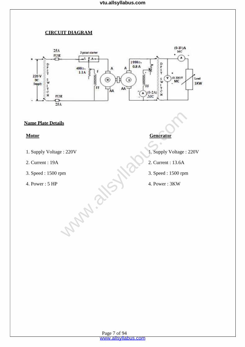
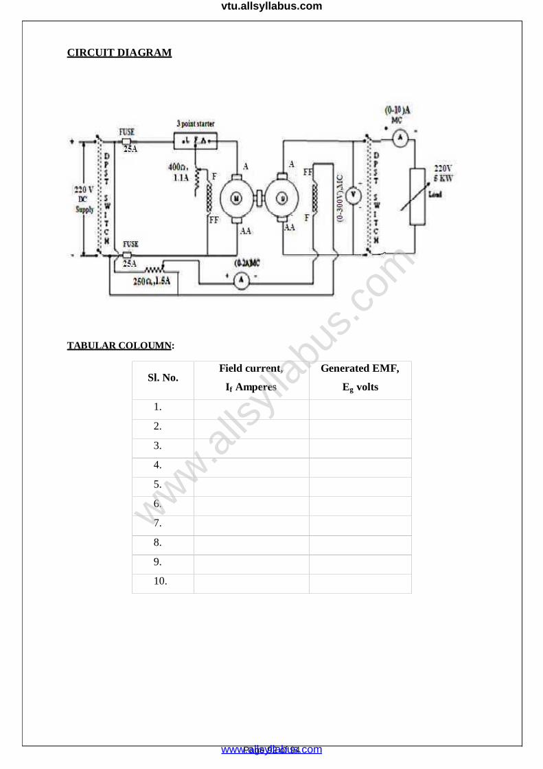
CIRCUIT DIAGRAM
Name Plate Details
Motor Generator
1. Supply Voltage : 220V 1. Supply Voltage : 220V
2. Current : 19A 2. Current : 13.6A
3. Speed : 1500 rpm 3. Speed : 1500 rpm
4. Power : 5 HP 4. Power : 3KW
Page 7 of 94
www.alls
yllab
us.co
m
www.allsyllabus.com
vtu.allsyllabus.com
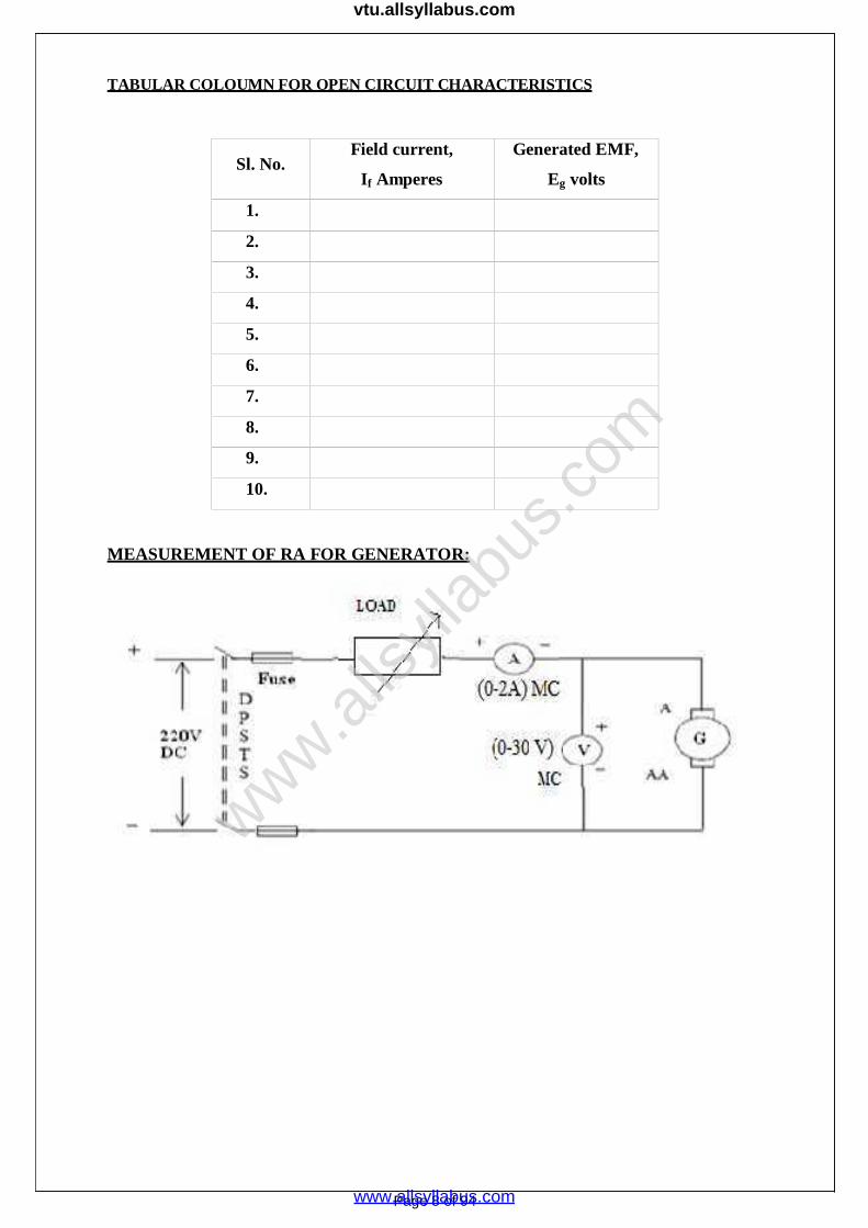
TABULAR COLOUMN FOR OPEN CIRCUIT CHARACTERISTICS
Sl. No.Field current,
If Amperes
Generated EMF,
Eg volts
1.
2.
3.
4.
5.
6.
7.
8.
9.
10.
MEASUREMENT OF RA FOR GENERATOR:
Page 8 of 94
www.alls
yllab
us.co
m
www.allsyllabus.com
vtu.allsyllabus.com
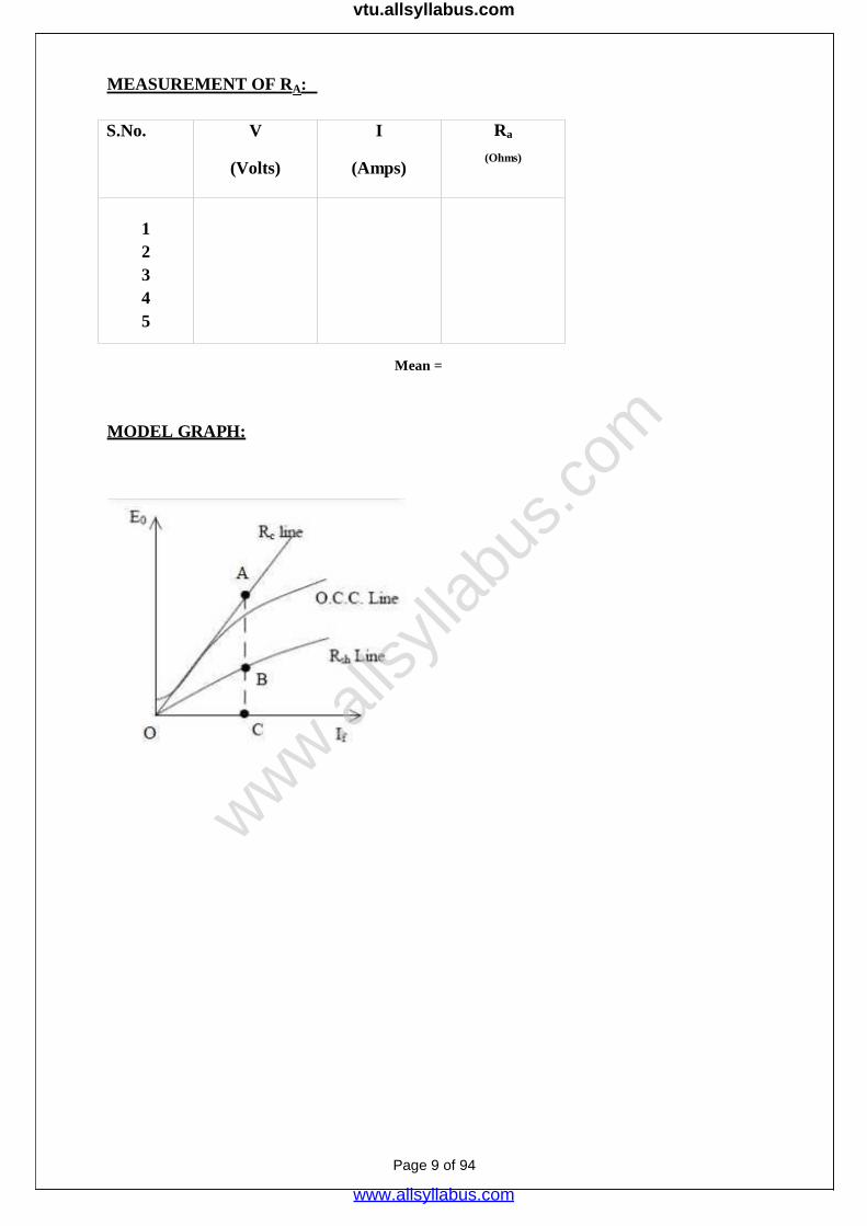
MEASUREMENT OF RA:
S.No. V
(Volts)
I
(Amps)
Ra
(Ohms)
12345
Mean =
MODEL GRAPH:
Page 9 of 94
www.alls
yllab
us.co
m
www.allsyllabus.com
vtu.allsyllabus.com
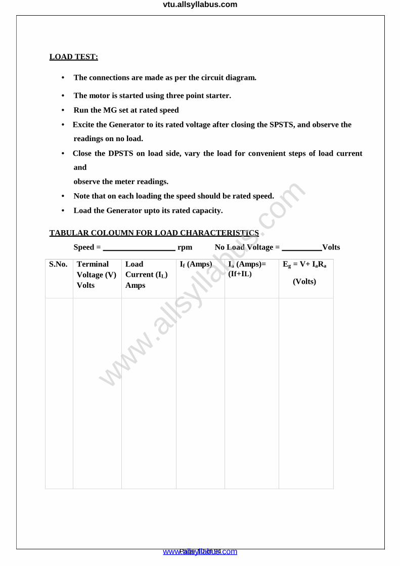
LOAD TEST:
The connections are made as per the circuit diagram.
The motor is started using three point starter.
Run the MG set at rated speed
Excite the Generator to its rated voltage after closing the SPSTS, and observe the
readings on no load.
Close the DPSTS on load side, vary the load for convenient steps of load current
and
observe the meter readings.
Note that on each loading the speed should be rated speed.
Load the Generator upto its rated capacity.
TABULAR COLOUMN FOR LOAD CHARACTERISTICS
Speed = rpm No Load Voltage = Volts
S.No. TerminalVoltage (V)Volts
LoadCurrent (IL)Amps
If (Amps) Ia (Amps)=(If+IL)
Eg = V+ IaRa
(Volts)
Page 10 of 94
www.alls
yllab
us.co
m
www.allsyllabus.com
vtu.allsyllabus.com

Formulas Required:
Load test:
For self excitation Ia = IL + If
So, induced emf on load, Eg = V + IaRa
MODEL GRAPHS:
Internal characteristics
External characteristics
Inference :
RESULT:
Thus the open circuit and load characteristics of self excited D.C. Shunt Generator weredrawn.
Page 11 of 94
www.alls
yllab
us.co
m
www.allsyllabus.com
vtu.allsyllabus.com
EXP. NO:
DATE:
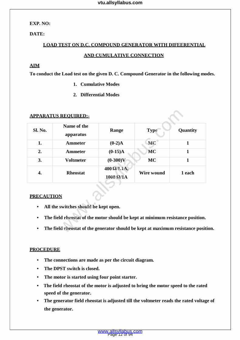
LOAD TEST ON D.C. COMPOUND GENERATOR WITH DIFEERENTIAL
AND CUMULATIVE CONNECTION
AIM
To conduct the Load test on the given D. C. Compound Generator in the following modes.
1. Cumulative Modes
2. Differential Modes
APPARATUS REQUIRED:-
Sl. No.Name of the
apparatusRange Type Quantity
1. Ammeter (0-2)A MC 1
2. Ammeter (0-15)A MC 1
3. Voltmeter (0-300)V MC 1
4. Rheostat400 Ω/1.1A,
1000 Ω/1AWire wound 1 each
PRECAUTION
All the switches should be kept open.
The field rheostat of the motor should be kept at minimum resistance position.
The field rheostat of the generator should be kept at maximum resistance position.
PROCEDURE
The connections are made as per the circuit diagram.
The DPST switch is closed.
The motor is started using four point starter.
The field rheostat of the motor is adjusted to bring the motor speed to the rated
speed of the generator.
The generator field rheostat is adjusted till the voltmeter reads the rated voltage of
the generator.
Page 12 of 94
www.alls
yllab
us.co
m
www.allsyllabus.com
vtu.allsyllabus.com

DPST switch on the generator side is closed.
The load is increased in steps.
At each step of loading all the meter readings are noted.
The above procedure is repeated till the ammeter reads the rated current.
Switch off the load gradually and make the motor and generator rheostat resistance
position as instructed in the precaution.
Turn off the supply
Interchange the terminal connection of the generator series field coil and repeat the
procedure right from the first step.
Page 13 of 94
www.alls
yllab
us.co
m
www.allsyllabus.com
vtu.allsyllabus.com

CIRCUIT DIAGRAM
DIFFERENTIAL SHUNT
CUMULATIVE SHUNT
Name Plate Details
Motor Generator
1.Supply Voltage: 220V 1. Supply Voltage:220V
2. Current:19A 2. Current:13.6A
3.Speed :1500 rpm 3. Speed:1500 rpm
4. Power: 5 HP 4. Power: 3KW
www.alls
yllab
us.co
m
www.allsyllabus.com
vtu.allsyllabus.com

TABULAR COLOUMN
CUMULATIVE COMPOUND MOTOR
Sl. No. IL (A) VL (V)
1.
2.
3.
4.
5.
6.
7.
8.
DIFFERENTIAL COMPOUND MOTOR
Sl. No. IL (A) VL (V)
1.
2.
3.
4.
5.
6.
7.
8.
Page 15 of 94
www.alls
yllab
us.co
m
www.allsyllabus.com
vtu.allsyllabus.com

MODEL GRAPHS:
Inference :
RESULT
Thus the performance characteristics of the DC Compound Generator were drawn.
Page 16 of 94
www.alls
yllab
us.co
m
www.allsyllabus.com
vtu.allsyllabus.com
EXP. NO:
DATE:
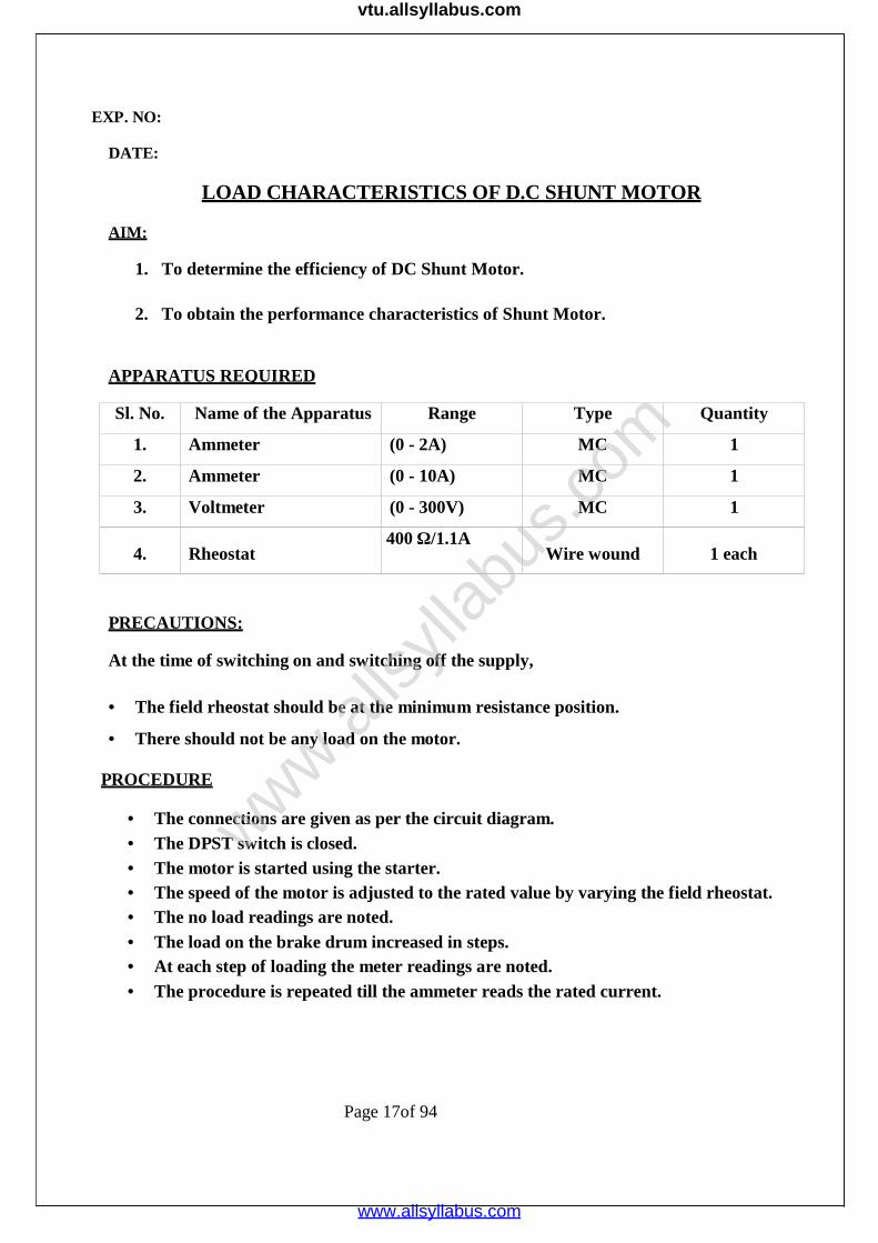
LOAD CHARACTERISTICS OF D.C SHUNT MOTOR
AIM:
1. To determine the efficiency of DC Shunt Motor.
2. To obtain the performance characteristics of Shunt Motor.
APPARATUS REQUIRED
Sl. No. Name of the Apparatus Range Type Quantity
1. Ammeter (0 - 2A) MC 1
2. Ammeter (0 - 10A) MC 1
3. Voltmeter (0 - 300V) MC 1
4. Rheostat400 Ω/1.1A
Wire wound 1 each
PRECAUTIONS:
At the time of switching on and switching off the supply,
The field rheostat should be at the minimum resistance position.
There should not be any load on the motor.
PROCEDURE
The connections are given as per the circuit diagram. The DPST switch is closed. The motor is started using the starter. The speed of the motor is adjusted to the rated value by varying the field rheostat. The no load readings are noted. The load on the brake drum increased in steps. At each step of loading the meter readings are noted. The procedure is repeated till the ammeter reads the rated current.
Page 17of 94
www.alls
yllab
us.co
m
www.allsyllabus.com
vtu.allsyllabus.com

CIRCUIT DIAGRAM FOR BRAKE TEST ON D.C. SHUNT MOTOR
Name Plate Details
Motor
1. Supply Voltage: 220V
2. Current:12A
3. Speed :1500 rpm
4. Power: 3 Hp
Page 18 of 94
www.alls
yllab
us.co
m
www.allsyllabus.com
vtu.allsyllabus.com

Page 19 of 94
TABULAR COLOUMN
Radius of brake drum, r = mts.
S.N
o.
V (Volts) I (Amps) Spring Balance (Kg) Speed
NS1 S2 S1~ S2
Torque
T
Output
Power
Input
Power
Efficie
ncy
(rpm) (Nm) Po
(Watts)
Pi η %
(Watts)
www.alls
yllab
us.co
m
www.allsyllabus.com
vtu.allsyllabus.com
Page 20 of 94
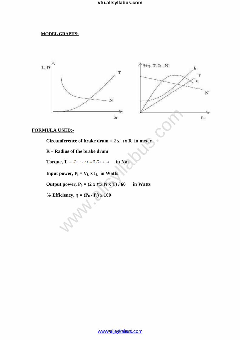
MODEL GRAPHS:
FORMULA USED:-
Circumference of brake drum = 2 x x R in meter
R – Radius of the brake drum
Torque, T = in Nm
Input power, Pi = VL x IL in Watts
Output power, P0 = (2 x x N x T) / 60 in Watts
% Efficiency, = (P0 / Pi) x 100
www.alls
yllab
us.co
m
www.allsyllabus.com
vtu.allsyllabus.com

Page 21 of 94
Inference:
RESULT:
Thus the performance characteristics of the DC Shunt Motor were drawn.
www.alls
yllab
us.co
m
www.allsyllabus.com
vtu.allsyllabus.com
Page 22 of 94
EXP:
DATE:
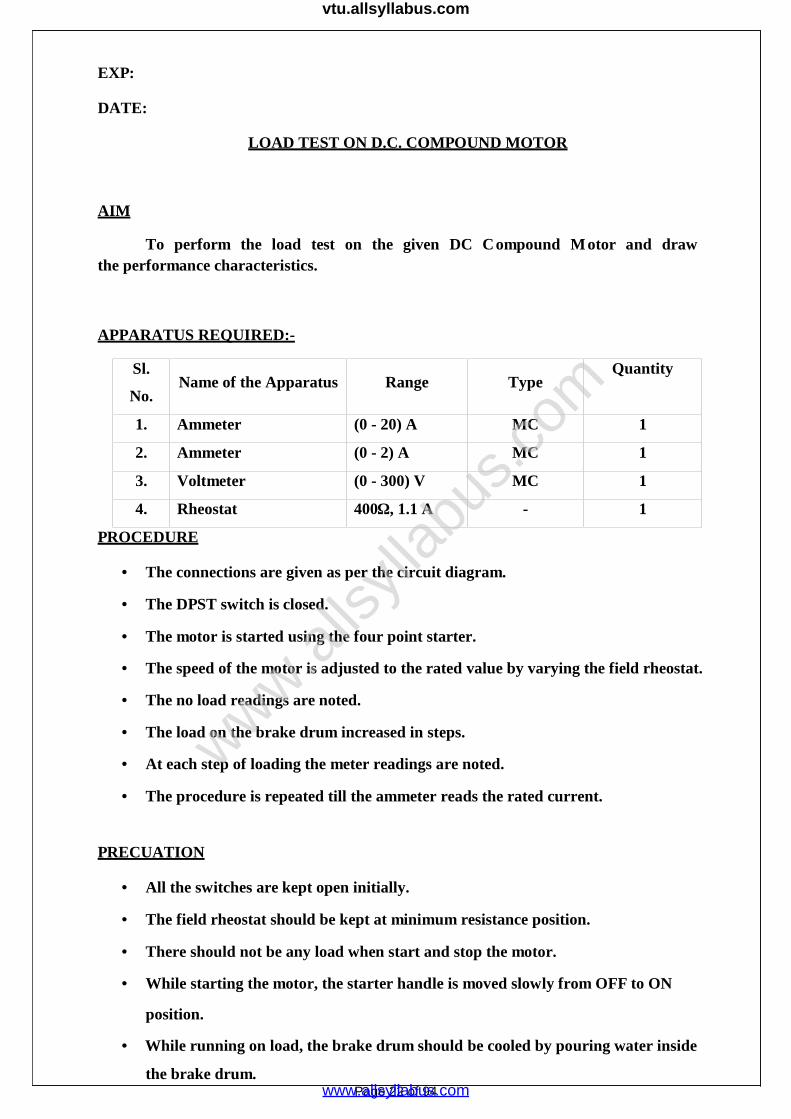
LOAD TEST ON D.C. COMPOUND MOTOR
AIM
To perform the load test on the given DC Compound M otor and drawthe performance characteristics.
APPARATUS REQUIRED:-
Sl.
No.Name of the Apparatus Range Type
Quantity
1. Ammeter (0 - 20) A MC 1
2. Ammeter (0 - 2) A MC 1
3. Voltmeter (0 - 300) V MC 1
4. Rheostat 400Ω, 1.1 A - 1
PROCEDURE
The connections are given as per the circuit diagram.
The DPST switch is closed.
The motor is started using the four point starter.
The speed of the motor is adjusted to the rated value by varying the field rheostat.
The no load readings are noted.
The load on the brake drum increased in steps.
At each step of loading the meter readings are noted.
The procedure is repeated till the ammeter reads the rated current.
PRECUATION
All the switches are kept open initially.
The field rheostat should be kept at minimum resistance position.
There should not be any load when start and stop the motor.
While starting the motor, the starter handle is moved slowly from OFF to ON
position.
While running on load, the brake drum should be cooled by pouring water inside
the brake drum.
www.alls
yllab
us.co
m
www.allsyllabus.com
vtu.allsyllabus.com
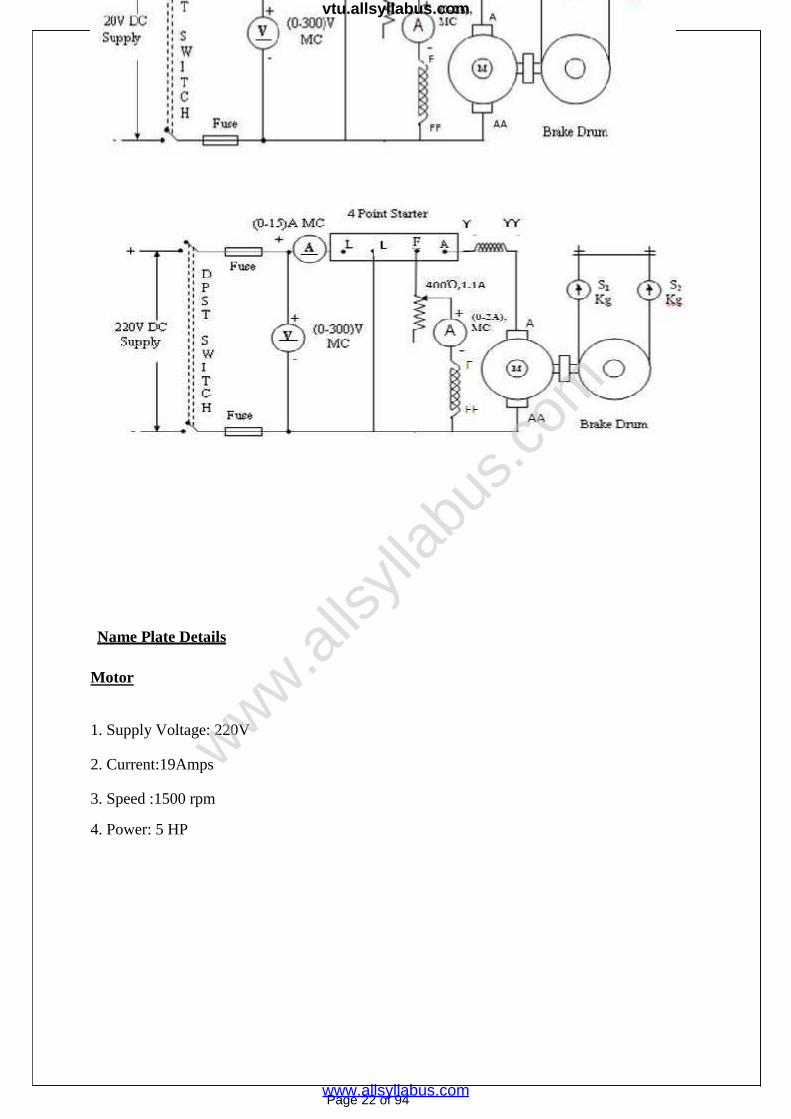
CIRCUIT DIAGRAM LOAD TEST ON DC COMPOUND MOTOR:
Name Plate Details
Motor
1. Supply Voltage: 220V
2. Current:19Amps
3. Speed :1500 rpm
4. Power: 5 HP
Page 22 of 94
www.alls
yllab
us.co
m
www.allsyllabus.com
vtu.allsyllabus.com
Page 23 of 94
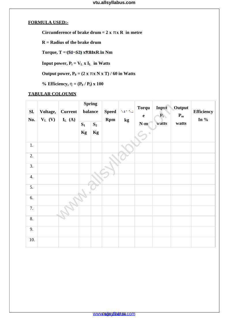
FORMULA USED:-
Circumference of brake drum = 2 x x R in metre
R = Radius of the brake drum
Torque, T = (S1~S2) x9.81xR in Nm
Input power, Pi = VL x IL in Watts
Output power, P0 = (2 x x N x T) / 60 in Watts
% Efficiency, = (P0 / Pi) x 100
TABULAR COLOUMN
Sl.
No.
Voltage,
VL (V)
Current
IL (A)
Spring
balance Speed
Rpm kg
Torqu
e
N-m
Input
Pi
watts
Output
Pm
watts
Efficiency
In %S1
Kg
S2
Kg
1.
2.
3.
4.
5.
6.
7.
8.
9.
10.
www.alls
yllab
us.co
m
www.allsyllabus.com
vtu.allsyllabus.com

Page 24 of 94
Inference:
RESULT:
MODEL GRAPHS:
Thus the performance characteristics of the DC Compound Motor were drawn.
www.alls
yllab
us.co
m
www.allsyllabus.com
vtu.allsyllabus.com

Page 25 of 94
EXP. NO:
DATE:
LOAD TEST ON D.C. SERIES MOTOR
AIM:
To determine the efficiency of D.C Series Motor.
To obtain the performance characteristics of DC Series Motor.
APPARATUS REQUIRED:
Sl.
No.
Name of the
ApparatusRange Type
Quantity
1. Ammeter (0-15)A MC 1
2. Voltmeter (0-300)V MC 1
PRECAUTION:
The motor should be started with some initial load.
PROCEDURE:
1. Connections are given as per circuit diagram.
2. Before starting the motor some initial load is applied to the motor by using the brake
drum with spring balance.
3. Using two-point starter the motor is started to run.
4. The meter readings are started at its initial condition.
5. Gradually load the machine up to rated current and corresponding meter readings
were noted.
6. After the observation of all the readings the load is released gradually up to the initial
load condition.
www.alls
yllab
us.co
m
www.allsyllabus.com
vtu.allsyllabus.com
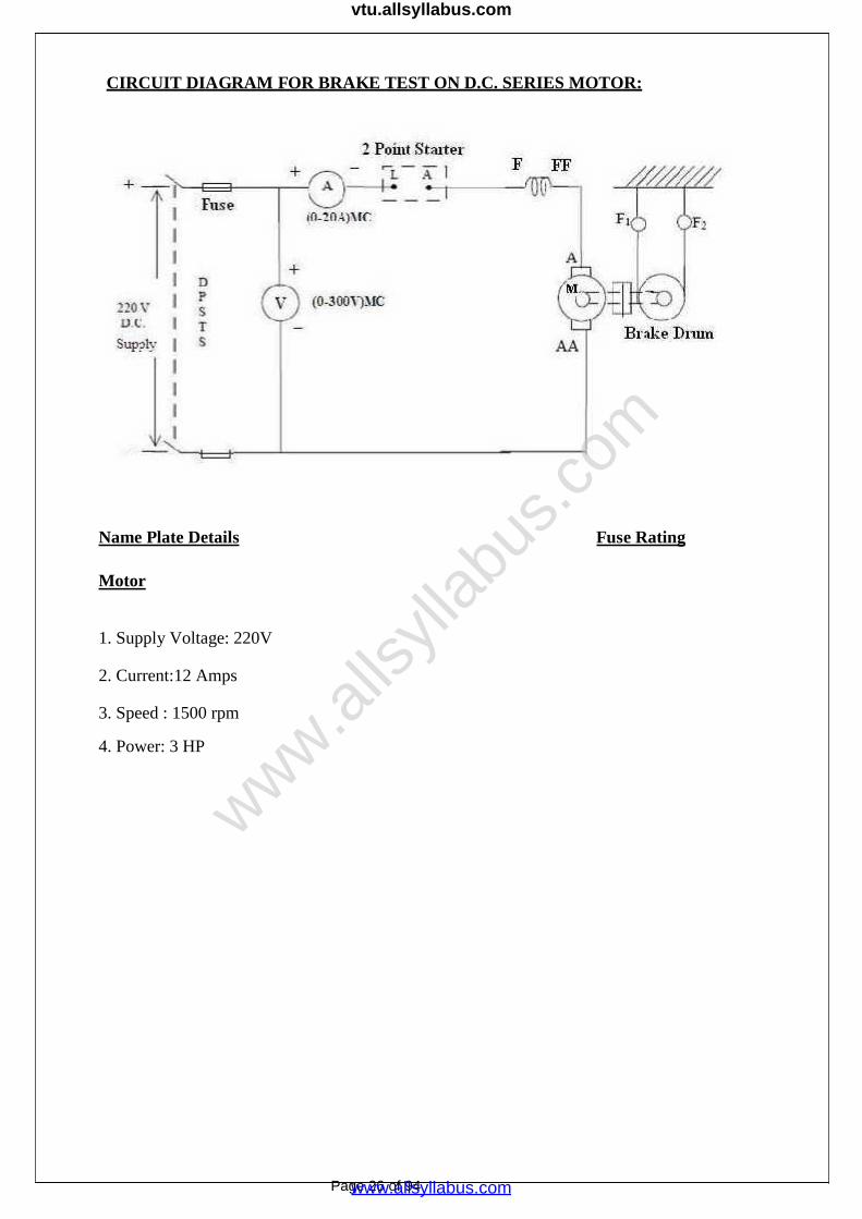
Name Plate Details Fuse Rating
CIRCUIT DIAGRAM FOR BRAKE TEST ON D.C. SERIES MOTOR:
Motor
1. Supply Voltage: 220V
2. Current:12 Amps
3. Speed : 1500 rpm
4. Power: 3 HP
Page 26 of 94
www.alls
yllab
us.co
m
www.allsyllabus.com
vtu.allsyllabus.com
Page 27 of 94
TABULAR COLOUMN
Radius of brake drum, r = mts.
S.No. VoltageVL
(Volts)
CurrentIL
(Amps)
Spring Balance (Kg) SpeedN
(rpm)
TorqueT
(Nm)
OutputPower
Po
(Watts)
InputPower Pi
(Watts)
Efficiencyη%
F1 F2 F1~ F2
1.
2.
3.
4.
www.alls
yllab
us.co
m
www.allsyllabus.com
vtu.allsyllabus.com

Page 28 of 94
MODEL GRAPHS:
FORMULAE USED:
Circumference of the brake drum = metre
Radius of the brake drum, r = metre
Torque applied on the shaft of the rotor, T = (F1 ~ F2)* r × 9.81 Nm
Output power, Po = (2πNT)/60 Watts
Input power Pi = V × IL Watts
Efficiency = (Po / Pi )
www.alls
yllab
us.co
m
www.allsyllabus.com
vtu.allsyllabus.com

Page 29 of 94
Inference:
RESULT:
Thus the performance characteristics of the DC Series Motor were drawn.
www.alls
yllab
us.co
m
www.allsyllabus.com
vtu.allsyllabus.com

Page 30 of 94
EXP.NO:
DATE
AIM:
SWINBURNE’S TEST
To predetermine the efficiency o the DC Machine when it act as
(i) Motor
(ii) Generator
APPARATUS REQUIRED:-
Sl.No. Name of the apparatus Range Type Quantity
1. Ammeter (0 -5) A MC 1
2. Ammeter (0 - 2) A MC 1
3. Voltmeter (0 - 300)V MC 1
4. Rheostat 400, 1.1 A Wire wound 1
5. Tachometer Digital 1
PRECAUTION:
1. The field rheostat should be kept at minimum resistance position.
2. There should be no load at the time of starting the experiment.
PROCEDURE:
1. The connections are made as per the circuit diagram.
2. The DPST switch is closed.
3. The motor is started with the help of three point starter.
4. The field rheostat of the motor is adjusted to bring the motor speed to the rated
value.
5. The no load current, voltage and shunt field current are noted.
Page 30 of 94
www.alls
yllab
us.co
m
www.allsyllabus.com
vtu.allsyllabus.com
Page 31 of 94
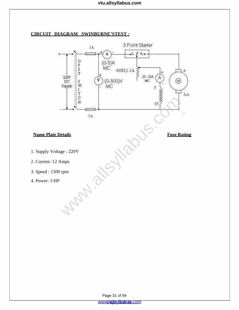
CIRCUIT DIAGRAM SWINBURNE’STEST :
Name Plate Details Fuse Rating
1. Supply Voltage : 220V
2. Current :12 Amps
3. Speed : 1500 rpm
4. Power: 3 HP
Page 31 of 94
www.alls
yllab
us.co
m
www.allsyllabus.com
vtu.allsyllabus.com

Page 32 of 94
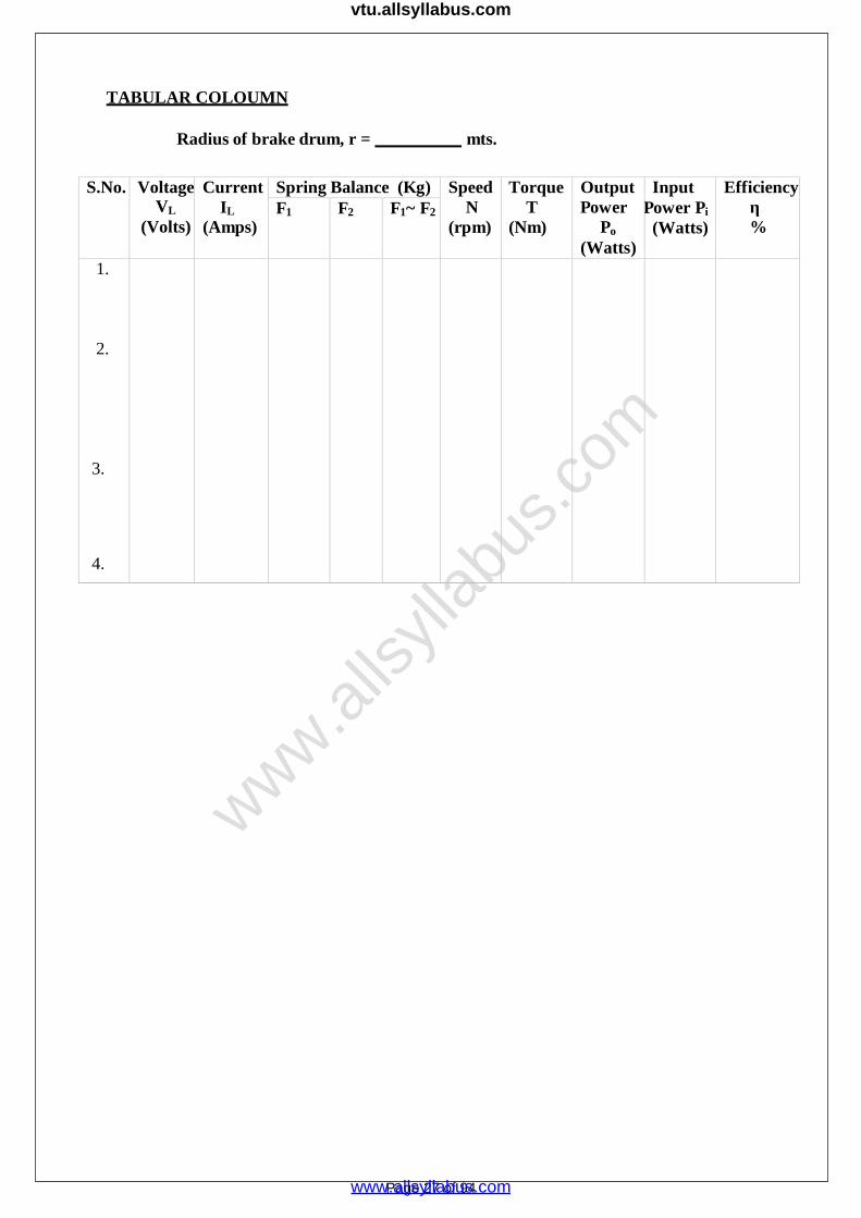
TABULAR COLOUMN
Voltage, V (volts)Field current, If
(A)
No load current, I0
(A)
For Motor
S.No
Line
Current
IL(A)
Field
Current
If (A)
Ia = IL -If
(A) WCu=I2
aR
Constant
Loss(watts)
Total
Loss
(watts)
Input
Power
(watts)
Output
Power
(watts)
Efficiency
%
www.alls
yllab
us.co
m
www.allsyllabus.com
vtu.allsyllabus.com

For Generator
S.No.
Line
Current,
IL
(A)
Field
current
If
(A)
Ia =
IL+If
(A)
WCu2= Ia
Ra
Constant
Loss(watts)
Total
Loss
(watts)
Input
Power
(watts)
Output
Power
(watts)
Efficiency
%
Page 33 of 94
www.alls
yllab
us.co
m
www.allsyllabus.com
vtu.allsyllabus.com
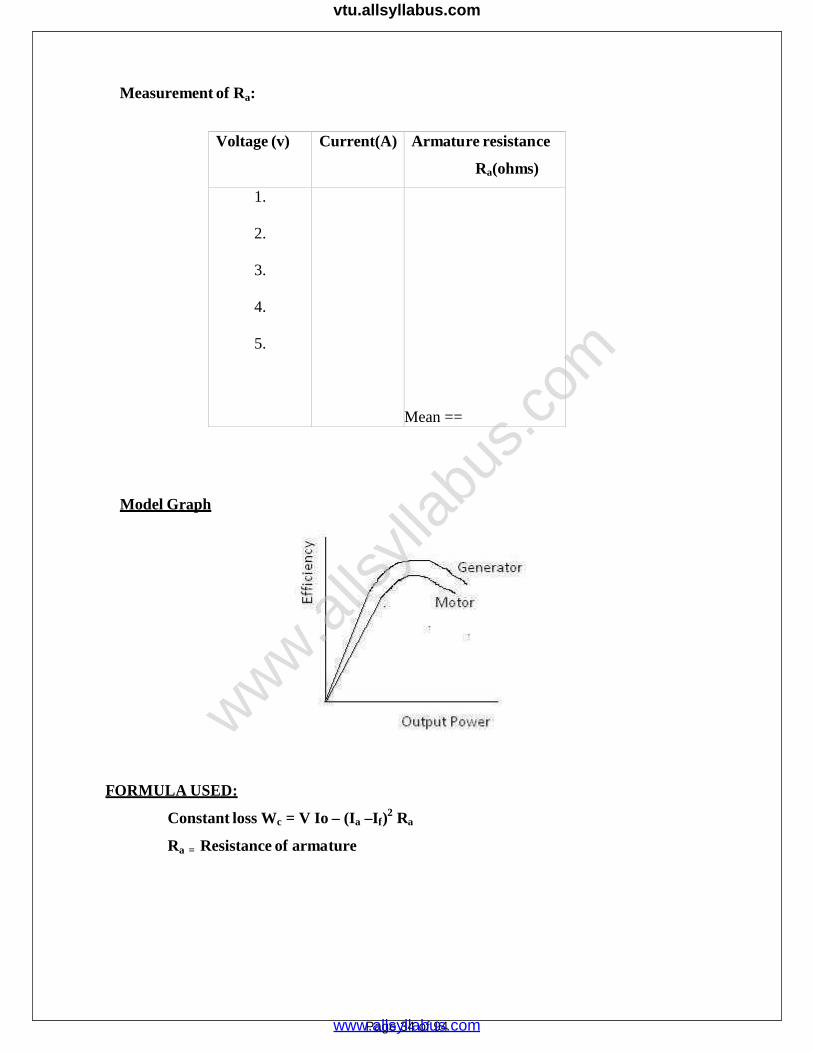
Measurement of Ra:
Voltage (v) Current(A) Armature resistance
Ra(ohms)
1.
2.
3.
4.
5.
Mean ==
Model Graph
FORMULA USED:
Constant loss Wc = V Io – (Ia –If)2 Ra
Ra = Resistance of armature
Page 34 of 94
www.alls
yllab
us.co
m
www.allsyllabus.com
vtu.allsyllabus.com
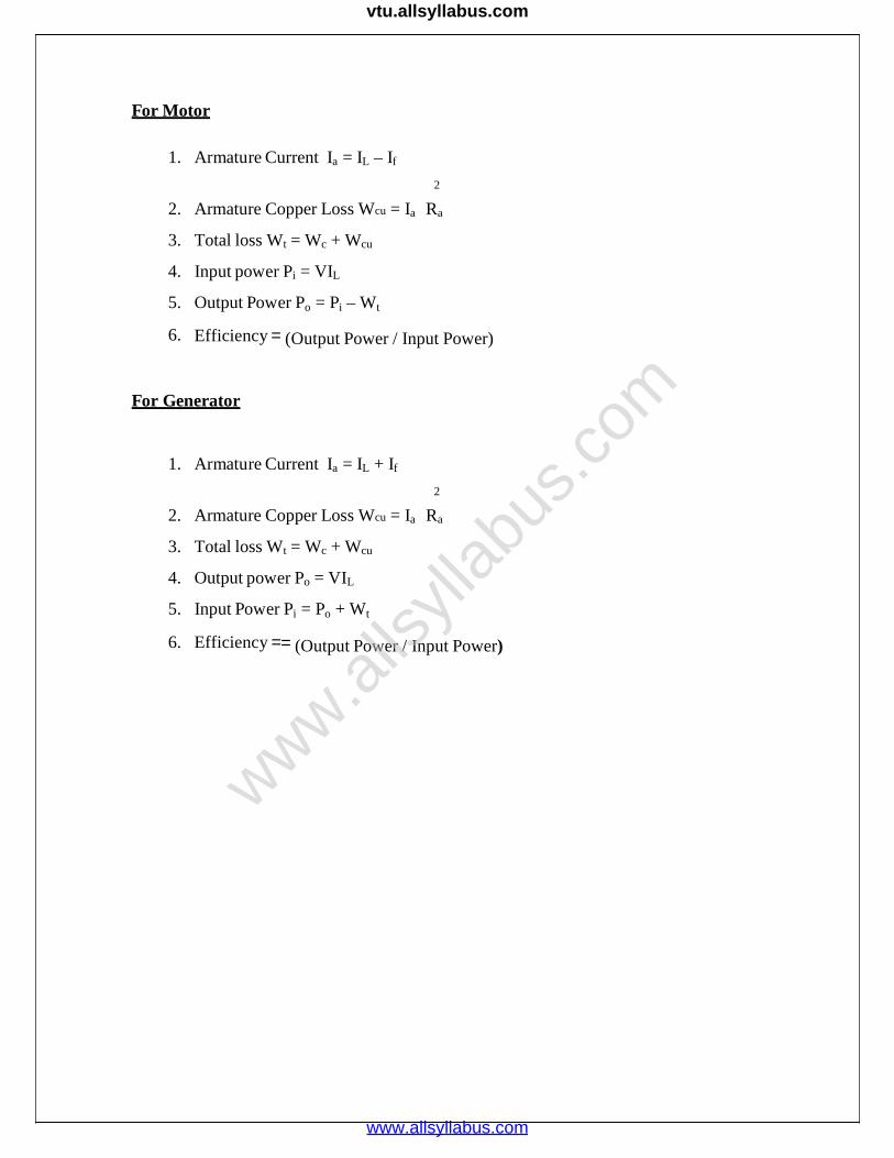
For Motor
1. Armature Current Ia = IL – If
2
2. Armature Copper Loss Wcu = Ia Ra
3. Total loss Wt = Wc + Wcu
4. Input power Pi = VIL
5. Output Power Po = Pi – Wt
6. Efficiency (Output Power / Input Power)
For Generator
1. Armature Current Ia = IL + If
2
2. Armature Copper Loss Wcu = Ia Ra
3. Total loss Wt = Wc + Wcu
4. Output power Po = VIL
5. Input Power Pi = Po + Wt
6. Efficiency (Output Power / Input Power)
www.alls
yllab
us.co
m
www.allsyllabus.com
vtu.allsyllabus.com

Inference:
RESULT:
Thus the efficiency of the DC Machine has been predetermined and
characteristics were drawn.
www.alls
yllab
us.co
m
www.allsyllabus.com
vtu.allsyllabus.com
EXP.NO:DATE
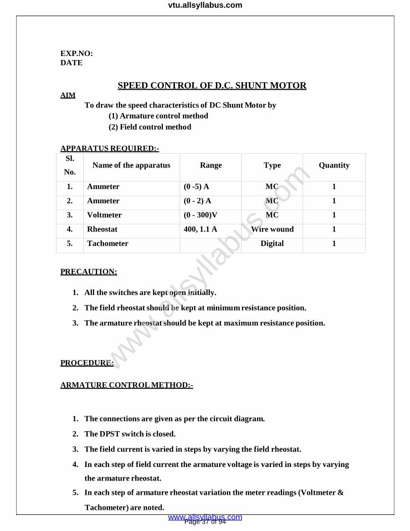
AIMSPEED CONTROL OF D.C. SHUNT MOTOR
To draw the speed characteristics of DC Shunt Motor by(1) Armature control method(2) Field control method
APPARATUS REQUIRED:-Sl.
No.Name of the apparatus Range Type Quantity
1. Ammeter (0 -5) A MC 1
2. Ammeter (0 - 2) A MC 1
3. Voltmeter (0 - 300)V MC 1
4. Rheostat 400, 1.1 A Wire wound 1
5. Tachometer Digital 1
PRECAUTION:
1. All the switches are kept open initially.
2. The field rheostat should be kept at minimum resistance position.
3. The armature rheostat should be kept at maximum resistance position.
PROCEDURE:
ARMATURE CONTROL METHOD:-
1. The connections are given as per the circuit diagram.
2. The DPST switch is closed.
3. The field current is varied in steps by varying the field rheostat.
4. In each step of field current the armature voltage is varied in steps by varying
the armature rheostat.
5. In each step of armature rheostat variation the meter readings (Voltmeter &
Tachometer) are noted.
Page 37 of 94
www.alls
yllab
us.co
m
www.allsyllabus.com
vtu.allsyllabus.com

FIELD CONTROL METHOD:-
1. The connections are given as per the circuit diagram.2. The DPST switch is closed.3. The armature voltage is varied in steps by varying the armature rheostat.4. In each step of armature voltage the field current in steps by varying the field
rheostat.5. In each step of field rheostat the meter readings (Ammeter & tachometer) are
noted.
Page 38 of 94
www.alls
yllab
us.co
m
www.allsyllabus.com
vtu.allsyllabus.com
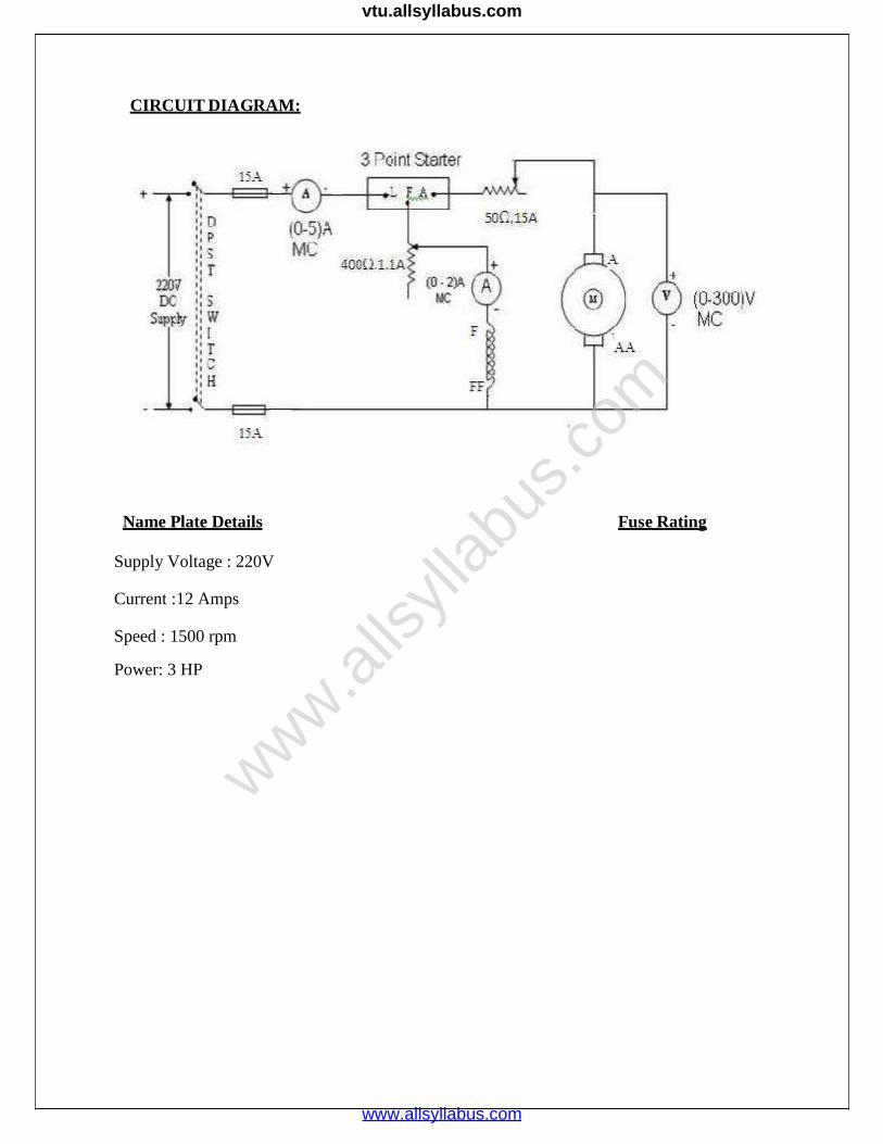
CIRCUIT DIAGRAM:
Name Plate Details Fuse Rating
Supply Voltage : 220V
Current :12 Amps
Speed : 1500 rpm
Power: 3 HP
www.alls
yllab
us.co
m
www.allsyllabus.com
vtu.allsyllabus.com
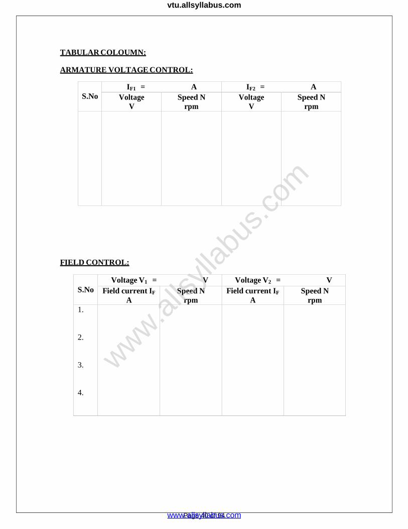
TABULAR COLOUMN:
ARMATURE VOLTAGE CONTROL:
S.NoIF1 = A IF2 = A
VoltageV
Speed Nrpm
VoltageV
Speed Nrpm
FIELD CONTROL:
S.NoVoltage V1 = V Voltage V2 = V
Field current IF
ASpeed N
rpmField current IF
ASpeed N
rpm1.
2.
3.
4.
Page 40 of 94
www.alls
yllab
us.co
m
www.allsyllabus.com
vtu.allsyllabus.com
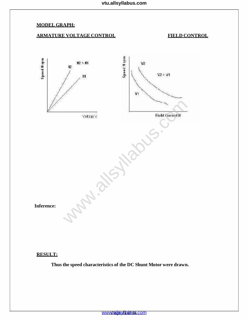
MODEL GRAPH:
ARMATURE VOLTAGE CONTROL FIELD CONTROL
Inference:
RESULT:
Thus the speed characteristics of the DC Shunt Motor were drawn.
Page 41 of 94
www.alls
yllab
us.co
m
www.allsyllabus.com
vtu.allsyllabus.com

EXP NO:
DATE:
HOPKINSON’STEST
AIM:
To conduct Hopkinson’s test on a pair of identical DC machines to pre-determine the efficiency of the machine as generator and as motor.
APPARATUS REQUIRED:
S.No. Apparatus Range Type Quantity
1 Ammeter(0-1)A
(0-10) AMCMC
12
2 Voltmeter(0-300) V(0-600)V
MCMC
11
3 Rheostats 400Ω, 1.1 A800Ω, 0.8 A
Wirewound
11
PRECATUIONS:
1. The field rheostat of the motor should be in the minimum position at the time
of starting and stopping the machine.
2. The field rheostat of the generator should be in the maximum position at the
time of starting and stopping the machine.
3. SPST switch should be kept open at the time of starting and stopping the
machine.
PROCEDURE:
1. Connections are made as per the circuit diagram.
2. After checking the minimum position of field rheostat of motor, maximum
position of field rheostat of generator, opening of SPST switch, DPST switch
is closed and starting resistance is gradually removed.
3. The motor is brought to its rated speed by adjusting the field rheostat of the
motor.
4. The voltmeter V1 is made to read zero by adjusting field rheostat of
generator and SPST switch is closed.
5. By adjusting field rheostats of motor and generator, various Ammeter
readings, voltmeter readings are noted.
6. The rheostats and SPST switch are brought to their original positions and
DPST switch is opened. Page 42 of 94
www.alls
yllab
us.co
m
www.allsyllabus.com
vtu.allsyllabus.com

CIRCUIT DIAGRAM FOR HOPKIN’S TEST
Name Plate Details
Motor Generator
Supply Voltage : 220V Supply Voltage : 220V
Current : 19Amps Current : 13.6Amps
Speed : 1500 rpm Speed : 1500
Power : 5 HP Power : 3KW
Fuse Rating
Page 43 of 94
www.alls
yllab
us.co
m
www.allsyllabus.com
vtu.allsyllabus.com

MODEL GRAPH:
As a Generator
% η
As a Motor
OUTPUT POWER P0 (W)
TABULAR COLUMN:
S.No.SupplyVoltageVS (V)
IS
(A)IFM
(A)VA
(A)IFG
(A)ILG
(A)
Page 44 of 94
www.alls
yllab
us.co
m
www.allsyllabus.com
vtu.allsyllabus.com
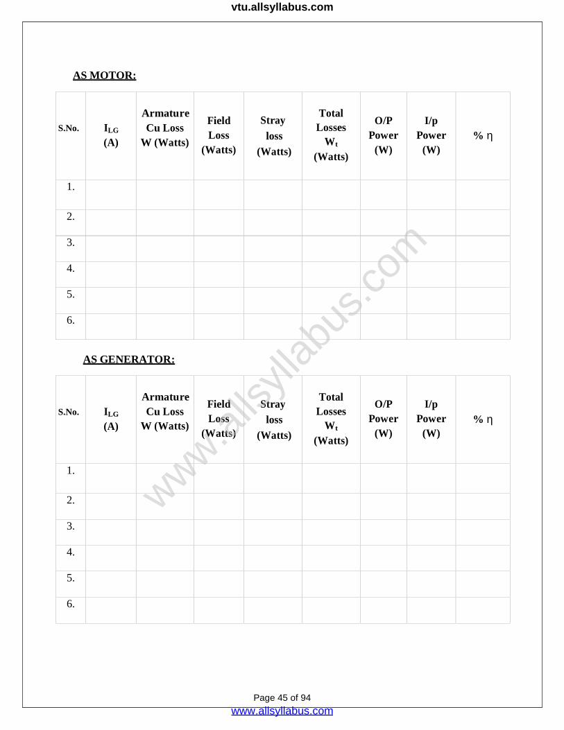
AS MOTOR:
S.No. ILG
(A)
ArmatureCu Loss
W (Watts)
FieldLoss
(Watts)
Strayloss
(Watts)
TotalLosses
Wt
(Watts)
O/PPower
(W)
I/pPower
(W)%
1.
2.
3.
4.
5.
6.
AS GENERATOR:
S.No. ILG
(A)
ArmatureCu Loss
W (Watts)
FieldLoss
(Watts)
Strayloss
(Watts)
TotalLosses
Wt
(Watts)
O/PPower
(W)
I/pPower
(W)%
1.
2.
3.
4.
5.
6.
Page 45 of 94
www.alls
yllab
us.co
m
www.allsyllabus.com
vtu.allsyllabus.com

2
FORMULAE USED:
Input Power = VI1watts
Motor armature cu loss = (I1+ I2)2 Ra watts
Generator armature cu loss = I22 Ra watts
Total Stray losses W = V I1 - (I1+I2)2 Ra + I 2
Stray loss per machine = W/2 watts.
Ra watts.
Page 46 of 94
www.alls
yllab
us.co
m
www.allsyllabus.com
vtu.allsyllabus.com

AS MOTOR:
Input Power = Armature input + Shunt field input
= (I1+ I2) V + I3V = (I1+I2+I3) V
Total Losses = Armature Cu loss + Field loss + stray loss
(I1 + I2)2 Ra + VI3 + W/2 watts
Input power – Total Losses
Efficiency % = ------------------------------------- x 100%
Input Power
AS GENERATOR:
Output Power = VI2 watts
Total Losses = Armature Cu loss+ Field Loss + Stray loss
= I22 Ra + VI4 + W/2 watts
Output power
Efficiency % = -------------------------------------- x 100%
Output Power+ Total Losses
www.alls
yllab
us.co
m
www.allsyllabus.com
vtu.allsyllabus.com

Inference:
RESULT:Thus Hopkinson’s test is conducted on a pair of identical DC machines the
efficiency of the machine as generator and as motor are pre-determined.
www.alls
yllab
us.co
m
www.allsyllabus.com
vtu.allsyllabus.com

EXP.NO:DATE
LOAD TEST ON SINGLE PHASE TRANSFORMER
AIM:
To determine the efficiency and also to find the variation of secondary terminal
voltage with respect to the load current.
APPARATUS REQUIRED:
S.No. Item Type Range Quantity
1 Auto Transformer 230/(0-270) V, 1φ - 1
2 Wattmeter300 V, 5A
150 V, 5 A
UPF
UPF
1
1
3 Ammeter(0-10) A
(0-5) A
MI
MI
1
1
4 Voltmeter
(0-300) V
(0-150) V
MI
MI
1
1
5 Connecting Wires 2.5sq.mm Copper Few
6 Load (5 KW,230V) - 1
PRECAUTION:
1.The Variac should be kept in minimum position while switching on and switching off
the supply side DPSTS.
2. At the time of switching on the supply there should not be any load connected.
Page 49 of 94
www.alls
yllab
us.co
m
www.allsyllabus.com
vtu.allsyllabus.com

1
RANGE FIXING:
Rated primary current, I Rated capacityin VA
Primary voltage, V1
Rated secondary current, I2 Rated capacityin VA
Secondaryvoltage, V2
The load used is resistive in nature.
The range of Ap, Vp, Wp are …………A, ……………V, …………W respectively.
The range of As, Vs, Ws are ……………A, …………….V, …………..W respectively.
PROCEDURE:
1. Excite the transformer to its rated voltage on no load.
2. Observe the meter readings at no load.
3. Gradually load the transformer and note the meter readings for each
loading.
4. Load the transformer to its rated capacity i.e. till it draws rated current from
the supply.
Note that applied voltage to the primary side should be kept at its rated voltage on
loading.
FORMULA USED:
Output power = WS
Input Power = WP
% =WS 100WP
V V% Regulation = S0 S 100
VS 0
(where VS0 – no load secondary rated terminal voltage)
Page 50 of 94
www.alls
yllab
us.co
m
www.allsyllabus.com
vtu.allsyllabus.com

CIRCUIT DIAGRAM:
VRL-Variable Resistive Load
Name Plate Details
1. Single phase transformer
2. Primary voltage: 230V3. Secondary voltage:115V4. Power capacity:1KVA
Page 51 of 94
www.alls
yllab
us.co
m
www.allsyllabus.com
vtu.allsyllabus.com

TABULAR COLUMN:
MODEL GRAPHS:
Inference:
RESULT:
Thus the efficiency and regulation of a Three phase Transformer werecalculated.
Page 52 of 94
Sl.No.
VP
Volts
IP
Amps
WP (Watts) VS
Volts
IS
Amps
WS (Watts) %
Efficiency
%Regula
tionObserved Actual Observed Actual
www.alls
yllab
us.co
m
www.allsyllabus.com
vtu.allsyllabus.com

EXP NO:
DATE:
LOAD TEST ON A THREE PHASE TRANSFORMER
AIM:
loading.Determination of Regulation & Efficiency of three-phase transformer by direct
APPARATUS REQUIRED:-
Sl. No.Name of the
apparatusRange Type Quantity
1. Voltmeter 0-600 V MI 1
2. Voltmeter 0-300V MI 1
3. Ammeter 0-10A MI 1
4. Ammeter 0-20A MI 1
5. Wattmeter 600V,5/10A,UPF 1
6. Resistive load 3ph 415V,5kw 1
PRECAUTIONS:
All the switches should be kept open.
The auto transformer should be kept at minimum potential position.
PROCEDURE:
1) Connect the circuit as shown in figure.
2) Keep load on transformer at off position.
3) Keeping dimmer stat at zero position, switch on 3-Phase supply.
4) Now increase dimmer stat voltage for 440 V.
5) Note down the no-load readings.
6) Then increase the load in steps till rated current of the transformer & note
down corresponding readings.
7) Calculate efficiency & regulation for each reading.
www.alls
yllab
us.co
m
www.allsyllabus.com
vtu.allsyllabus.com
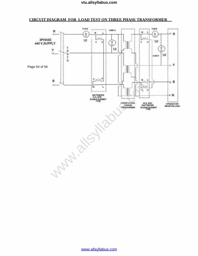
CIRCUIT DIAGRAM FOR LOAD TEST ON THREE PHASE TRANSFORMER
Page 54 of 94
www.alls
yllab
us.co
m
www.allsyllabus.com
vtu.allsyllabus.com
Page 55 of 94
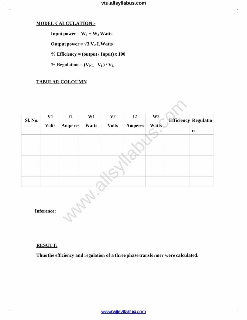
MODEL CALCULATION:-
Input power = W1 + W2 Watts
Output power = √3 V2 I2Watts
% Efficiency = (output / Input) x 100
% Regulation = (VNL - VL) / VL
TABULAR COLOUMN
Sl. No.V1
Volts
I1
Amperes
W1
Watts
V2
Volts
I2
Amperes
W2
WattsEfficiency Regulatio
n
Inference:
RESULT:
Thus the efficiency and regulation of a three phase transformer were calculated.
www.alls
yllab
us.co
m
www.allsyllabus.com
vtu.allsyllabus.com
Page 56 of 94
EXP. NO:
DATE:
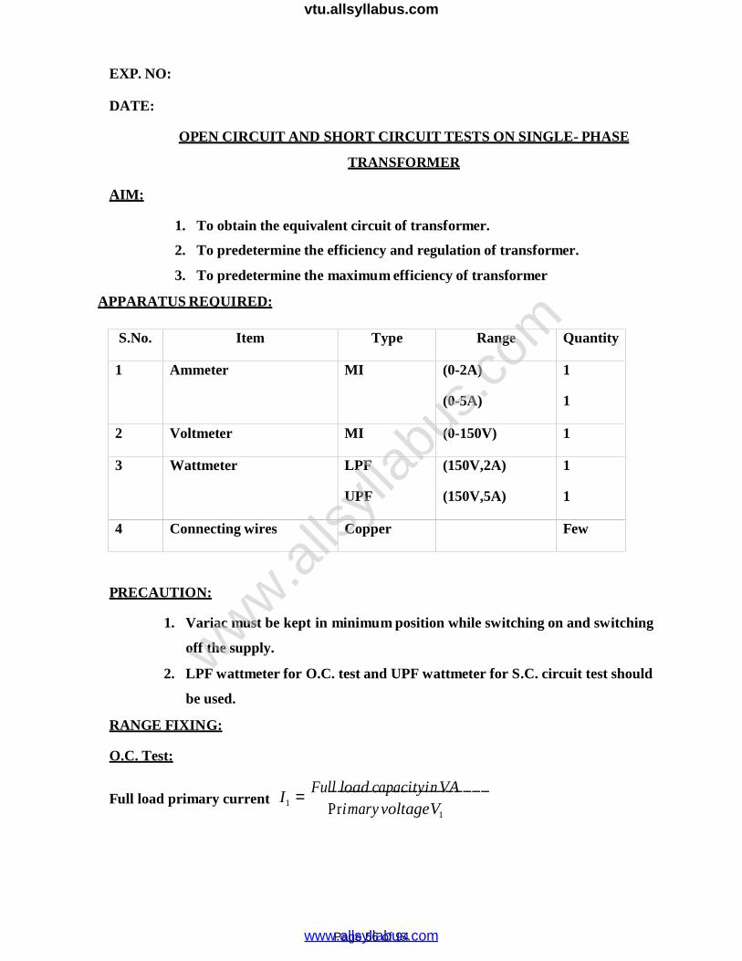
OPEN CIRCUIT AND SHORT CIRCUIT TESTS ON SINGLE- PHASE
TRANSFORMER
AIM:
1. To obtain the equivalent circuit of transformer.
2. To predetermine the efficiency and regulation of transformer.
3. To predetermine the maximum efficiency of transformer
APPARATUS REQUIRED:
S.No. Item Type Range Quantity
1 Ammeter MI (0-2A)
(0-5A)
1
1
2 Voltmeter MI (0-150V) 1
3 Wattmeter LPF
UPF
(150V,2A)
(150V,5A)
1
1
4 Connecting wires Copper Few
PRECAUTION:
1. Variac must be kept in minimum position while switching on and switching
off the supply.
2. LPF wattmeter for O.C. test and UPF wattmeter for S.C. circuit test should
be used.
RANGE FIXING:
O.C. Test:Full load capacityinVA
Full load primary current I1
Primary voltageV1
www.alls
yllab
us.co
m
www.allsyllabus.com
vtu.allsyllabus.com

Page 57 of 94
Full load capacityinVAFull load secondary current I2 SecondaryvoltageV2
Let both O.C. and S.C. test be conducted on primary side.
On O.C. test the current drawn by the transformer is about 5 – 10% of Full load
Primary current. Ammeter range is (0 - )A
The rated primary voltage will be applied. Voltmeter range (0 - )V
Observation:
O.C. Test: S.C. Test:
M.F. = M.F. =
V0
(Volts)
I0
(Amps)
W0 (Watts)
Observed Actual
Vsh
(Volts)
Ish
(Amps)
Wsh (Watts)
Observed Actual
www.alls
yllab
us.co
m
www.allsyllabus.com
vtu.allsyllabus.com
Page 58 of 94
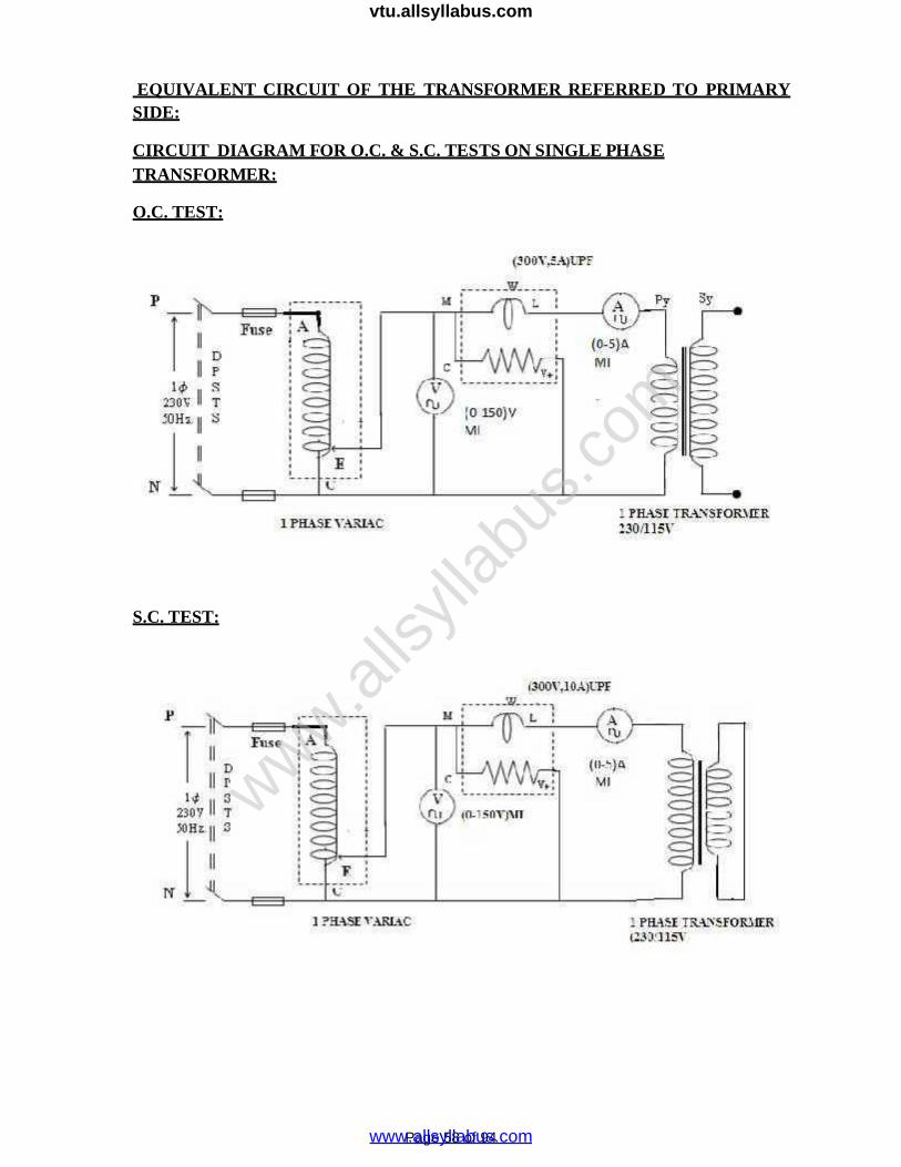
EQUIVALENT CIRCUIT OF THE TRANSFORMER REFERRED TO PRIMARYSIDE:
CIRCUIT DIAGRAM FOR O.C. & S.C. TESTS ON SINGLE PHASETRANSFORMER:
O.C. TEST:
S.C. TEST:
www.alls
yllab
us.co
m
www.allsyllabus.com
vtu.allsyllabus.com

Page 59 of 94
MODEL GRAPHS:
% regulation
% UPF
0.8 p.f.
Leading p.f. UPF Lagging
Po
WATTMETER:
The current rating and voltage rating of Wattmeter are to be nearer to the value
calculated above.
On O.C. condition the reactive power drawn is more and the active power drawn is less.
So power factor on no-load will be very low.
LPF wattmeter can be used.
The range of wattmeter is V, A, LPF.
S.C. TEST:
The voltage applied to the transformer primary to circulate rated full load current is
about 5 to 10% of rated primary voltage.
The voltmeter range is (0 - )V
Ammeter range is (0 - )A
The active power drawn by the transformer on S.C. condition is more and reactive
power drawn is less.UPF wattmeter can be used.
Range of wattmeter is ………V, ……….A, UPF.
www.alls
yllab
us.co
m
www.allsyllabus.com
vtu.allsyllabus.com
Page 60 of 94
I
PROCEDURE:
1. With the help of Variac, apply rated voltage to the transformer in O.C. test
and circulate rated current in S.C. test. Note down the corresponding meter
readings.
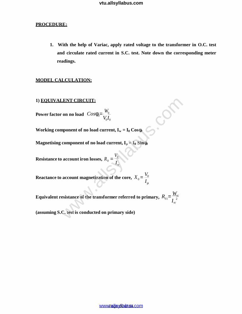
MODEL CALCULATION:
1) EQUIVALENT CIRCUIT:
Power factor on no load Cos0W0
V0I0
Working component of no load current, Iw = I0 Cos0
Magnetising component of no load current, I = I0 Sin0
Resistance to account iron losses, R0 V0
Iw
Reactance to account magnetization of the core, X 0 V0
I
Equivalent resistance of the transformer referred to primary, R Wsc01 2
sc
(assuming S.C. test is conducted on primary side)www.alls
yllab
us.co
m
www.allsyllabus.com
vtu.allsyllabus.com

Page 61 of 94
S.No.
% ofload
x
Copperloss
Wc
=X2Wsc
(Watts)
T.L. =
Wi +Wc
(Watts)
Cos = 1 Cos = 0.8 Cos = 0.6
P
(Watts)
P
(Watts)
Po
(Watts
)
P
(Watts)
P
(Watts)
P
(Watts)
1
2
3
4
5
6
7
0
20
40
60
80
100
120
PREDETERMINATION OF EFFICIENCY:
o i i o i
www.alls
yllab
us.co
m
www.allsyllabus.com
vtu.allsyllabus.com
Page 62 of 94
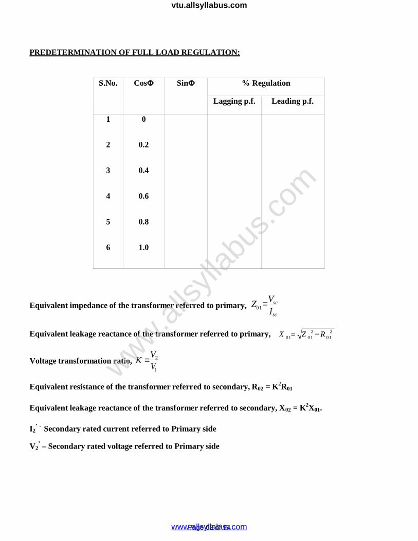
PREDETERMINATION OF FULL LOAD REGULATION:
S.No. CosΦ SinΦ % Regulation
Lagging p.f. Leading p.f.
1
2
3
4
5
6
0
0.2
0.4
0.6
0.8
1.0
Equivalent impedance of the transformer referred to primary, Z Vsc01 Isc
2 2Equivalent leakage reactance of the transformer referred to primary, X 01 Z 01 R 01
Voltage transformation ratio, K V2
V1
Equivalent resistance of the transformer referred to secondary, R02 = K2R01
Equivalent leakage reactance of the transformer referred to secondary, X02 = K2X01.
I2’ - Secondary rated current referred to Primary side
V2’ – Secondary rated voltage referred to Primary side
www.alls
yllab
us.co
m
www.allsyllabus.com
vtu.allsyllabus.com
Page 63 of 94
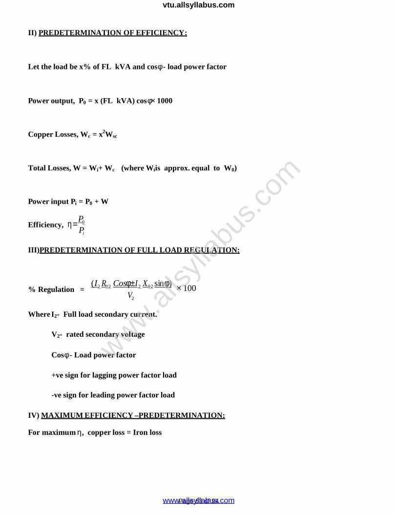
II) PREDETERMINATION OF EFFICIENCY:
Let the load be x% of FL kVA and cos - load power factor
Power output, P0 = x (FL kVA) cos 1000
Copper Losses, Wc = x2Wsc
Total Losses, W = Wi+ Wc (where Wiis approx. equal to W0)
Power input Pi = P0 + W
Efficiency, P0
Pi
III)PREDETERMINATION OF FULL LOAD REGULATION:
% Regulation =(I2 R02 CosI2 X02 sin)
V2
100
WhereI2- Full load secondary current.
V2- rated secondary voltage
Cos - Load power factor
+ve sign for lagging power factor load
-ve sign for leading power factor load
IV) MAXIMUM EFFICIENCY –PREDETERMINATION:
For maximum , copper loss = Iron loss
www.alls
yllab
us.co
m
www.allsyllabus.com
vtu.allsyllabus.com
Page 64 of 94
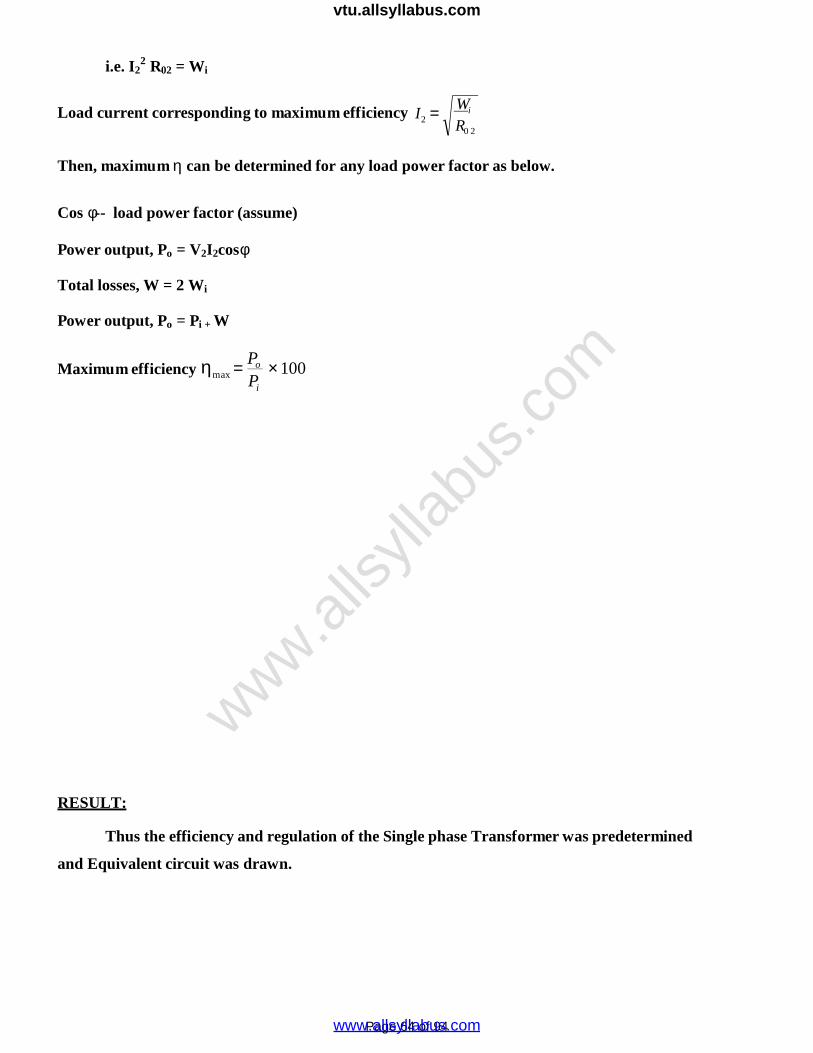
i.e. I22 R02 = Wi
Load current corresponding to maximum efficiency I2 Wi
R0 2
Then, maximum can be determined for any load power factor as below.
Cos -- load power factor (assume)
Power output, Po = V2I2cosTotal losses, W = 2 Wi
Power output, Po = Pi + W
Maximum efficiency
max Po 100
Pi
RESULT:
Thus the efficiency and regulation of the Single phase Transformer was predetermined
and Equivalent circuit was drawn.
www.alls
yllab
us.co
m
www.allsyllabus.com
vtu.allsyllabus.com
Page 65 of 94
POLARITY TEST ON SINGLE PHASE TRANSFORMEREXP.NO:DATE:
AIM:
To determine the polarity of a Single phase Transformer
APPARATUS REQUIRED:
S. No. Name of the Apparatus Range Type Quantity
1. Auto Transformer 230/(0-270) V - 2
2. Voltmeter (0 -600)V MI 3
3. Connecting Wires 2.5sq.mm Copper Few
PRECAUTION:
1. Auto transformer must be kept in minimum position while switching on and switching
off the supply.
2. Transformer should be operated under rated values.
PROCEDURE:
1. Connect the circuit as shown circuit diagram.
2. Switch on the single phase AC supply.
3. Record the voltages V1 V2 and V3. In Case V3< V1 polarity is subtractive.
4. Repeat the step 3 after connecting terminals A1 and a2. In case V3> V1 polarity is additive.
5. Switch of the supply.
www.alls
yllab
us.co
m
www.allsyllabus.com
vtu.allsyllabus.com
Page 66 of 94
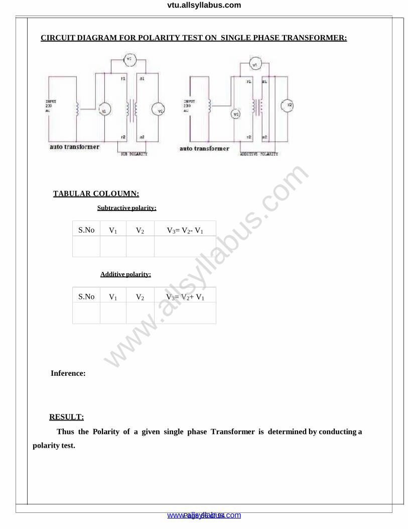
CIRCUIT DIAGRAM FOR POLARITY TEST ON SINGLE PHASE TRANSFORMER:
TABULAR COLOUMN:
Subtractive polarity:
S.No V1 V2 V3= V2- V1
Additive polarity:
S.No V1 V2 V3= V2+ V1
Inference:
RESULT:
Thus the Polarity of a given single phase Transformer is determined by conducting a
polarity test.
www.alls
yllab
us.co
m
www.allsyllabus.com
vtu.allsyllabus.com

Page 67 of 94
www.alls
yllab
us.co
m
www.allsyllabus.com
vtu.allsyllabus.com

Page 68 of 94
EXP.NO:
DATE:
SUMPNER’STESTON TRANSFORMERS
AIM :To predetermine the Efficiency and Regulation of a given Single phase Transformer by
conducting back-to-back test.
APPARATUS REQUIRED:
S. No. Name of the Apparatus Range Type Quantity
1. Auto Transformer 230/(0-270) V - 2
2. Wattmeter150 V, 2A
150 V, 5 A
LPF
UPF
1
1
3. Ammeter(0-2) A
(0-5) A
MI
MI
1
1
4. Voltmeter
(0-75) V
(0-150) V
(0 -600) V
MI
MI
MI
1
1
1
5. Connecting Wires 2.5sq.mm Copper Few
PRECAUTIONS:
1. Auto Transformer should be kept in zero position, before switching on the ac supply.
2. Transformer should be operated under rated
values.
FORMULA USED:
Core loss =Wo
Copper Loss= full load cu loss X (1/x)2
Total loss =Core loss +Cu loss
Output = V2 I2 Cosφ
Input= output + total loss
% Efficiency = output/input *100
POWER FACTOR ON NO LOAD:
CosΦ=(Wo/VoIo)
Working component IW=IO*CosΦ
Magnetizing component Iμ =IO*SinΦ Resistance Ro= Vo/Iw in Ω
www.alls
yllab
us.co
m
www.allsyllabus.com
vtu.allsyllabus.com
c
FOR SHORT CIRCUIT TEST:
Equivalent resistance R01= Wsc / Is2
Equivalent impedance Z01= Vsc / Isc in Ω
Equivalent leakage reactance X01= √(Z012-R01
2) in Ω
Voltage ratio= V2/V1
R02=K2*R01
X02=K2*X01
PERCENTAGE OF REGULATION
Lagging PF = (I2R02 CosΦ+ I2X02 SinΦ)/ V2
Leading PF = (I2R02 CosΦ- I2X02 SinΦ)/ V2
PROCEDURE:
1. Connections are made as shown in the circuit diagram.
2. Rated voltage of 110V is adjusted to get in voltmeter by adjusting the variac of the
Auto Transformer which would be in zero before switching on the supply at the primary side.
3. The readings of voltmeter, ammeter and wattmeter are noted on the primary side.
4. A voltmeter is connected across the secondary and with the secondary supply off i.e switch
S is kept open. The voltmeter reading is noted.
5. If the reading of voltmeter reads higher voltage, the terminals of any one of secondary
coil is interchanged in order that voltmeter reads zero.
6. The secondary is now switched on and SPST switch is closed with variac of auto
transformer is zero.
7. After switching on the secondary the variac of transformer (Auto) is adjusted so that full
load rated secondary current flows.
8. Then the readings of wattmeter, Ammeter and voltmeter are noted.
9. The Percentage Efficiency and percentage regulation are calculated and equivalentcircuit is drawn.
www.alls
yllab
us.co
m
www.allsyllabus.com
vtu.allsyllabus.com
Page 70 of 94
CIRCUIT DIAGRAM:
www.alls
yllab
us.co
m
www.allsyllabus.com
vtu.allsyllabus.com

Page 71 of 94
TABULAR COLUMN:
VO IO WO (watts) VSc ISc WSc (watts)(V) (A) OBSERVED ACTUAL (V) (A) OBSERVED ACTUAL
To find Efficiency
Load Core lossWo
(Watts)
Cu lossWc(Watts)
Total lossWT(watts)
Outputpower
Wo(watts)
Inputpower
Wi(watts)
% η
UPF 0.8 UPF 0.8 UPF 0.8
To find Regulation
Load Cosφ Sinφ I2Re2
CosφI2 Xe2
Sinφ%Regulation
LAG LEAD
Inference:
RESULT:
Thus the efficiency and regulation of a given single phase Transformer is carried out by
conducting back-to-back test.
www.alls
yllab
us.co
m
www.allsyllabus.com
vtu.allsyllabus.com
Page 72 of 94
EXP NO:
DATE:
SEPARATION OF NO LOAD LOSSES IN A SINGLE PHASE TRANSFORMER
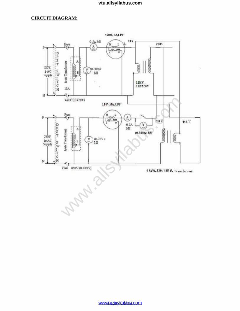
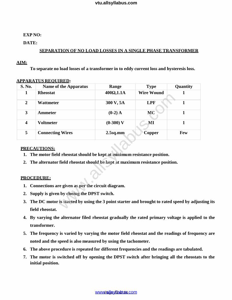
AIM:To separate no load losses of a transformer in to eddy current loss and hysteresis loss.
APPARATUS REQUIRED:S. No. Name of the Apparatus Range Type Quantity
1 Rheostat 400Ω,1.1A Wire Wound 1
2 Wattmeter 300 V, 5A LPF 1
3 Ammeter (0-2) A MC 1
4 Voltmeter (0-300) V MI 1
5 Connecting Wires 2.5sq.mm Copper Few
PRECAUTIONS:1. The motor field rheostat should be kept at minimum resistance position.
2. The alternator field rheostat should be kept at maximum resistance position.
PROCEDURE:
1. Connections are given as per the circuit diagram.
2. Supply is given by closing the DPST switch.
3. The DC motor is started by using the 3 point starter and brought to rated speed by adjusting its
field rheostat.
4. By varying the alternator filed rheostat gradually the rated primary voltage is applied to the
transformer.
5. The frequency is varied by varying the motor field rheostat and the readings of frequency are
noted and the speed is also measured by using the tachometer.
6. The above procedure is repeated for different frequencies and the readings are tabulated.
7. The motor is switched off by opening the DPST switch after bringing all the rheostats to theinitial position.
www.alls
yllab
us.co
m
www.allsyllabus.com
vtu.allsyllabus.com
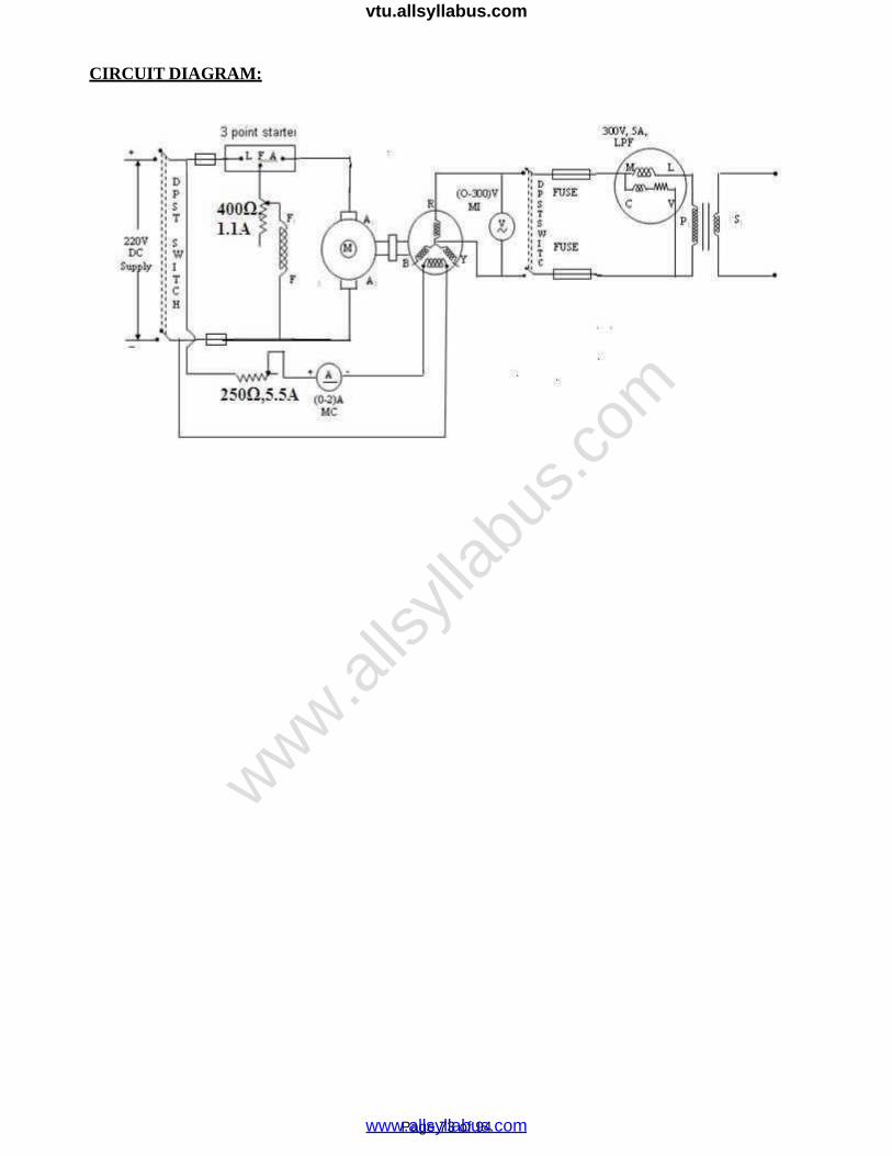
CIRCUIT DIAGRAM:
Page 73 of 94
www.alls
yllab
us.co
m
www.allsyllabus.com
vtu.allsyllabus.com

TABULAR COLUMN:
S.No. SpeedN (rpm)
Frequencyf (Hz)
VoltageV (Volts)
WattmeterreadingWatts
Iron lossWi (Watts)
Wi / fJoules
1.
2.
3.
4.
5.
6.
7.
8.
9.
Page 76 of 94
www.alls
yllab
us.co
m
www.allsyllabus.com
vtu.allsyllabus.com
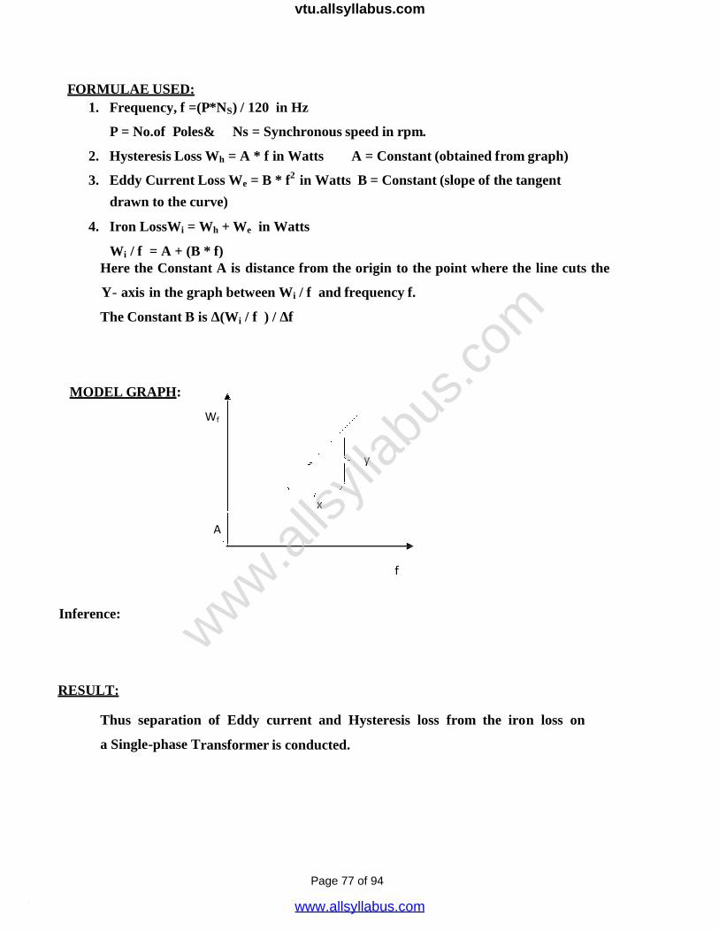
FORMULAE USED:1. Frequency, f =(P*NS) / 120 in Hz
P = No.of Poles& Ns = Synchronous speed in rpm.
2. Hysteresis Loss Wh = A * f in Watts A = Constant (obtained from graph)
3. Eddy Current Loss We = B * f2 in Watts B = Constant (slope of the tangent
drawn to the curve)
4. Iron LossWi = Wh + We in Watts
Wi / f = A + (B * f)Here the Constant A is distance from the origin to the point where the line cuts the
Y- axis in the graph between Wi / f and frequency f.
The Constant B is Δ(Wi / f ) / Δf
MODEL GRAPH:
Wf
y
x
A
f
Inference:
RESULT:
Thus separation of Eddy current and Hysteresis loss from the iron loss on
a Single-phase Transformer is conducted.
Page 77 of 94
www.alls
yllab
us.co
m
www.allsyllabus.com
vtu.allsyllabus.com
EXP NO:
DATE:
STUDY OF STARTERS AND THREE PHASE CONNECTIONS OF A TRANSFORMER
AIM:
To Study about the starters and Three phase connection of a Transformer.
EQUIPMENT REQUIRED:
Sl No. Name of the Apparatus Quantity
1 Two Point starter 1
2 Three Point starter 1
3 Four Point starter 1
4 DOL Starter 1
5 Auto transformer Starter 1
6 Star-Delta Starter 1
7 Rotor Resistance Starter 1
THEORY :
The value of the armature current in a D.C Shunt Motor is givenby
Ia = ( V – Eb )/ Ra
WhereV = applied voltage.
Ra = armature resistance.
E b = Back .e.m.f .
Page 78 of 94
www.alls
yllab
us.co
m
www.allsyllabus.com
vtu.allsyllabus.com
In practice the value of the armature resistance is of the order of 1 ohms and at the instant of starting the value
of the back e.m.f is zero volts. Therefore under starting conditions the value of the armature current is very
high. This high inrush current at the time of starting may damage the motor. To protect the motor from such
dangerous current the D.C motors are always started using starters.
The types of D.C motor starters are
i) Two point starters
ii) Three point starters
iii) Four point starters.
The functions of the starters are
i) It protects the from dangerous high
speed. ii) It protects the motor from
overloads.
i) TWO POINT STARTERS
It is used for starting D.C. series motors which has the problem of over speeding due to the loss of
load from its shaft. Here for starting the motor the control arm is moved in clock-wise direction from its OFF
position to the ON position against the spring tension. The control arm is held in the ON position by the
electromagnet E. The exciting coil of the hold-on electromagnet E is connected in series with the armature
circuit. If the motor loses its load, current decreases and hence the strength of the electromagnet also
decreases. The control arm returns to the OFF position due to the spring tension, Thus preventing the motor
from over speeding. The starter also returns to the OFF position when the supply voltage decreases
appreciably. L and F are the two points of the starter which are connected with the motor terminals
Page 79 of 94
www.alls
yllab
us.co
m
www.allsyllabus.com
vtu.allsyllabus.com

Page 80 of 94
www.alls
yllab
us.co
m
www.allsyllabus.com
vtu.allsyllabus.com

ii) THREE POINT STARTER: ( Refer fig 2 )
It is used for starting the shunt or compound motor. The coil of the hold on electromagnet E is connected
in series with the shunt field coil. In the case of disconnection in the field circuit the control arm will return to
its OFF position due to spring tension. This is necessary because the shunt motor will over speed if it loses
excitation. The starter also returns to the OFF position in case of low voltage supply or complete failure of the
supply. This protection is therefore is called No Volt Release (NVR).
Over load protection:
When the motor is over loaded it draws a heavy current. This heavy current also flows through the
exciting coil of the over load electromagnet ( OLR). The electromagnet then pulls an iron piece upwar6.ds
which short circuits the coils of the NVR coil. The hold on magnet gets de-energized and therefore the starter
arm returns to the OFF position, thus protecting the motor against overload. L, A and F are the three terminals
of the three point starter.
iii) FOUR POINT STARTER:
The connection diagram of the four point starter is shown in Fig 3. In a four point starter arm touches
the starting resistance, the current from the supply is divided into three paths. One through the starting
resistance and the armature, one through the field circuit, and one through the NVR coil. A protective
resistance is connected in series with the NVR coil. Since in a four point starter the NVR coil is independent
of the of the field ckt connection , the d.c motor may over speed if there is a break in the field circuit. A D.C
motor can be stopped by opening the main switch. The steps of the starting resistance are so designed that the
armature current will remain within the certain limits and will not change the torque developed by the motor to
a great extent.
Page 81 of 94
www.alls
yllab
us.co
m
www.allsyllabus.com
vtu.allsyllabus.com

Page 82 of 94
www.alls
yllab
us.co
m
www.allsyllabus.com
vtu.allsyllabus.com

Page 81 of 943
Three Phase Transformer Connections
The primary and secondary windings of a transformer can be connected in different configuration as
shown to meet practically any requirement. In the case of three phase transformer windings, three forms of
connection are possible: “star” (wye), “delta” (mesh) and “interconnected-star” (zig-zag). The combinations of
the three windings may be with the primary delta-connected and the secondary star- connected, or star-delta,
star-star or delta-delta, depending on the transformers use. When transformers are used to provide three or
more phases they are generally referred to as a Polyphase Transformer.
Three Phase Transformer Star and Delta Configurations
But what do we mean by “star” and “delta” three-phase transformer connection. A three phase
transformer has three sets of primary and secondary windings. Depending upon how these sets of windings are
interconnected, determines whether the connection is a star or delta configuration. The available voltage which
are each displaced from the other by 120 electrical degrees and flow of the transformers currents are also
decided by the type of the electrical connection used on both the primary and secondary sides. With three single-
phase transformers connected together, the magnetic flux’s in the three transformers differ in phase by 120 time-
degrees. With a single the three-phase transformer there are three magnetic flux’s in the
core differing in time-phase by 120 degrees.
www.alls
yllab
us.co
m
www.allsyllabus.com
vtu.allsyllabus.com
Page 82 of 943
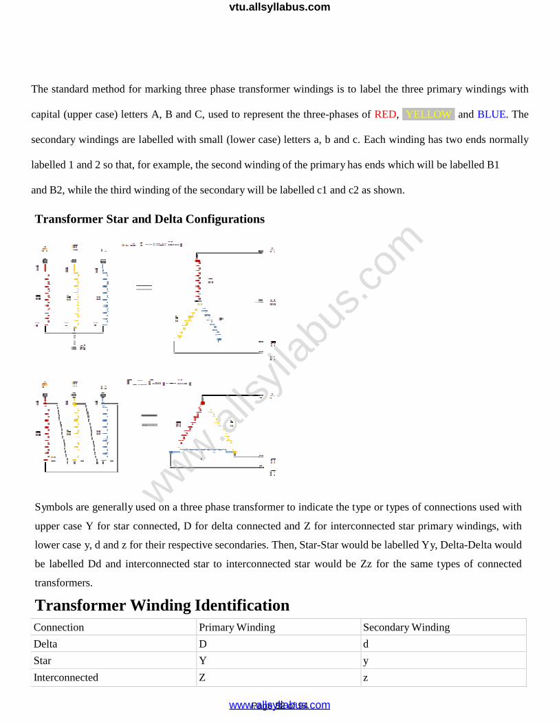
The standard method for marking three phase transformer windings is to label the three primary windings with
capital (upper case) letters A, B and C, used to represent the three-phases of RED, YELLOW and BLUE. The
secondary windings are labelled with small (lower case) letters a, b and c. Each winding has two ends normally
labelled 1 and 2 so that, for example, the second winding of the primary has ends which will be labelled B1
and B2, while the third winding of the secondary will be labelled c1 and c2 as shown.
Transformer Star and Delta Configurations
Symbols are generally used on a three phase transformer to indicate the type or types of connections used with
upper case Y for star connected, D for delta connected and Z for interconnected star primary windings, with
lower case y, d and z for their respective secondaries. Then, Star-Star would be labelled Yy, Delta-Delta would
be labelled Dd and interconnected star to interconnected star would be Zz for the same types of connected
transformers.
Transformer Winding IdentificationConnection Primary Winding Secondary Winding
Delta D d
Star Y y
Interconnected Z z
www.alls
yllab
us.co
m
www.allsyllabus.com
vtu.allsyllabus.com

Page 83 of 943
We now know that there are four ways in which three single-phase transformers may be
connected together between primary and secondary three-phase circuits. The configurations are delta-delta,
star-star, star-delta,
and delta-star. Transformers for high voltage operation with the star connections has the advantage of reducing
the voltage on an individual transformer, reducing the number of turns required and an increase in the size of
the conductors, making the coil windings easier and cheaper to insulate than delta transformers.
The delta-delta connection nevertheless has one big advantage over the star-delta configuration, in that if one
transformer of a group of three should become faulty or disabled, the two remaining ones will continue to
deliver three-phase power with a capacity equal to approximately two thirds of the original output from the
transformer unit.
www.alls
yllab
us.co
m
www.allsyllabus.com
vtu.allsyllabus.com
Page 84 of 943
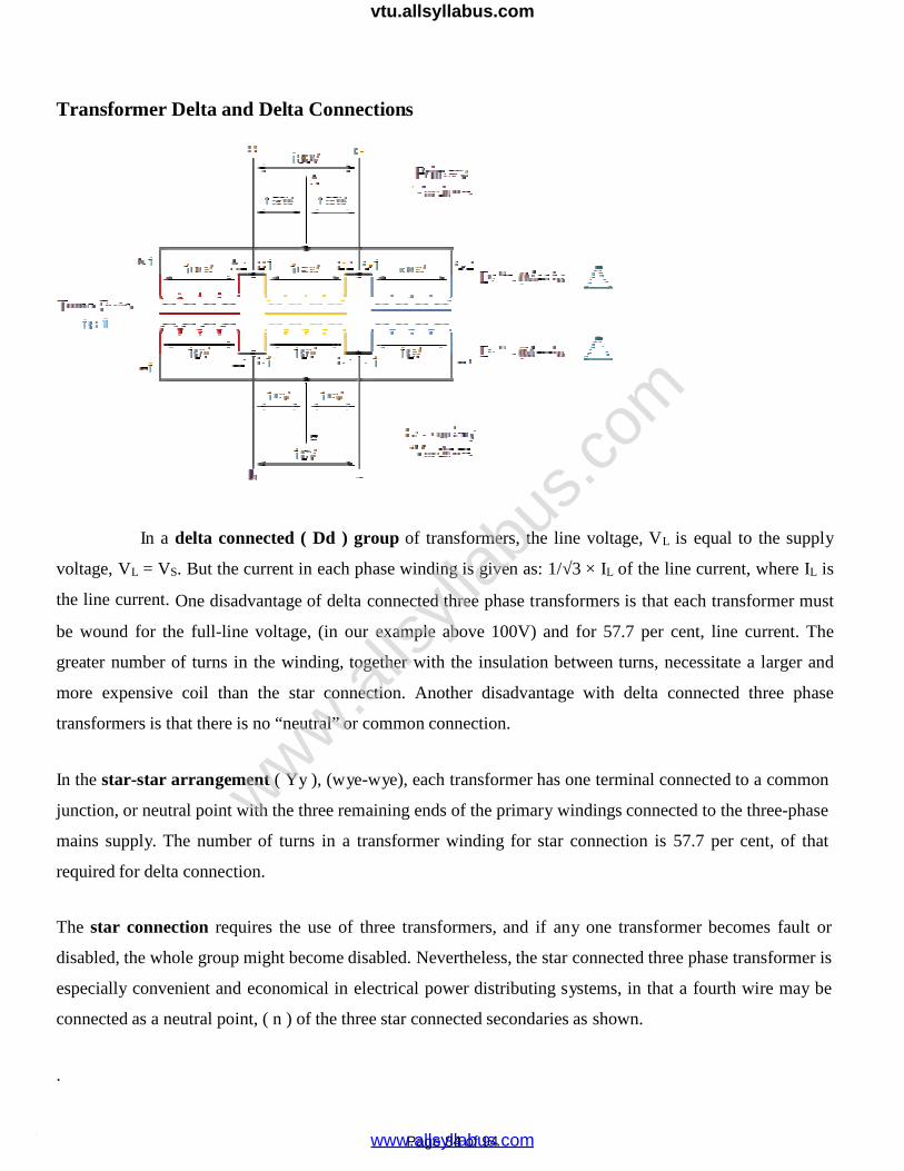
Transformer Delta and Delta Connections
In a delta connected ( Dd ) group of transformers, the line voltage, VL is equal to the supply
voltage, VL = VS. But the current in each phase winding is given as: 1/√3 × IL of the line current, where IL is
the line current. One disadvantage of delta connected three phase transformers is that each transformer must
be wound for the full-line voltage, (in our example above 100V) and for 57.7 per cent, line current. The
greater number of turns in the winding, together with the insulation between turns, necessitate a larger and
more expensive coil than the star connection. Another disadvantage with delta connected three phase
transformers is that there is no “neutral” or common connection.
In the star-star arrangement ( Yy ), (wye-wye), each transformer has one terminal connected to a common
junction, or neutral point with the three remaining ends of the primary windings connected to the three-phase
mains supply. The number of turns in a transformer winding for star connection is 57.7 per cent, of that
required for delta connection.
The star connection requires the use of three transformers, and if any one transformer becomes fault or
disabled, the whole group might become disabled. Nevertheless, the star connected three phase transformer is
especially convenient and economical in electrical power distributing systems, in that a fourth wire may be
connected as a neutral point, ( n ) of the three star connected secondaries as shown.
.
www.alls
yllab
us.co
m
www.allsyllabus.com
vtu.allsyllabus.com

Page 85 of 943
Transformer Star and Star Connections
The voltage between any line of the three-phase transformer is called the “line voltage”, VL, while the voltage
between any line and the neutral point of a star connected transformer is called the “phase voltage”, V P. This
phase voltage between the neutral point and any one of the line connections is 1/√3 × VL of the line voltage.
Then above, the primary side phase voltage, VP is given as.
Result:
www.alls
yllab
us.co
m
www.allsyllabus.com
vtu.allsyllabus.com

Page 91 of 94
EXP.NO.DATE:
OPEN CIRCUIT AND LOAD CHARACTERISTICS OF SEPERATELY EXCITED D.C
GENERATOR
AIM:
To obtain open circuit and load characteristics of separately excited d.c shunt
generator.
APPARATUS REQUIRED:
S.No. Apparatus Range Type Quantity1 Ammeter (0-1)A MC 12 Voltmeter (0-300)V MC 13 Rheostats 400Ω , 0.8A Wire 2
PRECAUTION
All the switches are kept open initially.
The motor field rheostat is kept at minimum resistance position.
The generator field rheostat is kept at maximum resistance position.
PROCEDURE
OPEN CIRCUIT CHARACTERISTICS:-
The connections are made as per the circuit diagram.
After checking minimum position of motor field rheostat, maximum position of
generator field rheostat, the supply side DPST switch is closed and starting
resistance is gradually removed.
The motor is started using three point starter.
By varying the field rheostat of the motor, the speed of the motor is adjusted to the
rated speed of the generator.
By varying the generator field rheostat, voltmeter and ammeter readings are taken.
After bringing the generator rheostat to maximum position, field rheostat of motor
to minimum position, the DPST switch is closed.
www.alls
yllab
us.co
m
www.allsyllabus.com
vtu.allsyllabus.com
Page 92 of 94
CIRCUIT DIAGRAM
TABULAR COLOUMN:
Sl. No.Field current,
If Amperes
Generated EMF,
Eg volts
1.
2.
3.
4.
5.
6.
7.
8.
9.
10.
www.alls
yllab
us.co
m
www.allsyllabus.com
vtu.allsyllabus.com

Page 93 of 94
MODEL GRAPH:-
OPEN CIRCUIT CHARACTERISTICS:-
MODEL CALCULATION:-
Armature current, Ia = IL = If
Generated EMF, Eg = (V + Ia Ra)
LOAD TEST:
Keeping the generator side DPST open, the field rheostat in the generator side is
adjusted for the rated voltage of the generator which is seen in the voltmeter.
Now the DPST switch is closed and the resistive load is put up on the generator step
by step. The terminal voltage, armature and load current values are noted down for
each step from the respective meters.
Note that while taking each set of readings, the field current is maintained constant
as that for rated voltage [because due to heating, shunt field resistance is
increased.
www.alls
yllab
us.co
m
www.allsyllabus.com
vtu.allsyllabus.com

TABULAR COLOUMN:
Sl.
No.
Voltage,
VL
(Volts)
Current, IL
(Amperes)
Armature
Current, Ia
(Amperes)
Generated
EMF, Eg
(Volts)
1.
2.
3.
4.
5.
6.
7.
8.
MODEL GRAPH:-
LOAD TEST:
MODEL CALCULATION:-
Armature current, Ia = IL = If
Generated EMF, Eg = (V + Ia Ra)
RESULT:
Thus the open circuit and load characteristics of Separately excited D.C. Shunt Generatorwere drawn.
www.alls
yllab
us.co
m
www.allsyllabus.com
vtu.allsyllabus.com
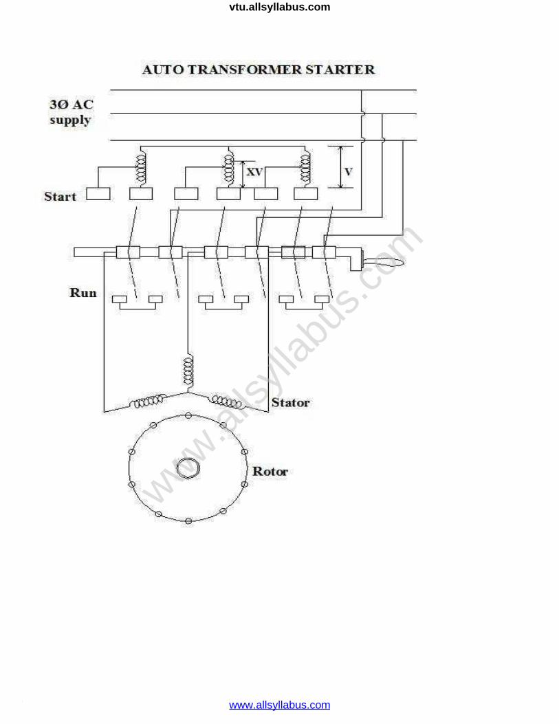
STUDY OF INDUCTION MOTOR STARTERS
AUTO –TRANSFORMER STARTING
An auto transformer starter consists of an auto transformer and a switch as shown in the fig. When
the switch S is put on START position, a reduced voltage is applied across the motor terminals. When the
motor picks up speed, say to 80 per cent of its mornal speed, the switch is put to RUN position. Then the
auto-transformer is cut out of the circuit and full rated voltage gets applied across the motor terminals.
The circuit dia in the fig is for a manual auto-transformer starter. This can be made push button
operated automatic controlled starter so that the contacts switch over from start to run position as the motor
speed picks up to 80% of its speed. Over-load protection relay has not been shown in the figure. The switch
S is air-break type for small motors and oil break type for large motors. Auto transformer may have
more than one tapping to enable the user select any suitable starting voltage depending upon the
conditions. Series resistors or reactors can be used to cause voltage drop in them and thereby allow low
voltage to be applied across the motor terminals at starting. These are cut out of the circuit as the motor picks
up speed.
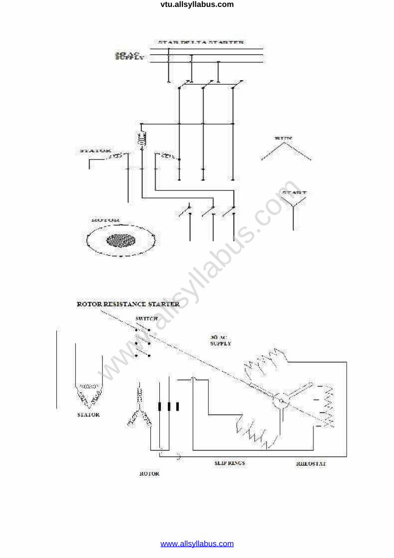
STAR-DELTA METHOD OF STARTING:
The startor phase windings are first connected in star and full voltage is connected across its free
terminals. As the motor picks up speed, the windings are disconnected through a switch and they are
reconnected in delta across the supply terminals. The current drawn by the motor from the lines is reduced
to as compared to the current it would have drawn if connected in delta.The motor windings, first in star and
then in delta the line current drawn by the motor at starting is reduced to one third as compared to starting
current with the windings delta-connected.
In making connections for star-delta starting, care should be taken such that sequence of supply
connections to the winding terminals does not change while changing from star connection to delta
connection. Otherwise the motor will start rotating in the opposite direction, when connections are
changed from star to delta. Star-delta starters are available for manual operation using push button
control. An automatic star – delta starter used time delay relays(T.D.R) through which star to delta
connections take place automatically with some pre-fixed time delay. The delay time of the T.D.R is fixed
keeping in view the starting time of the motor.
www.alls
yllab
us.co
m
www.allsyllabus.com
vtu.allsyllabus.com
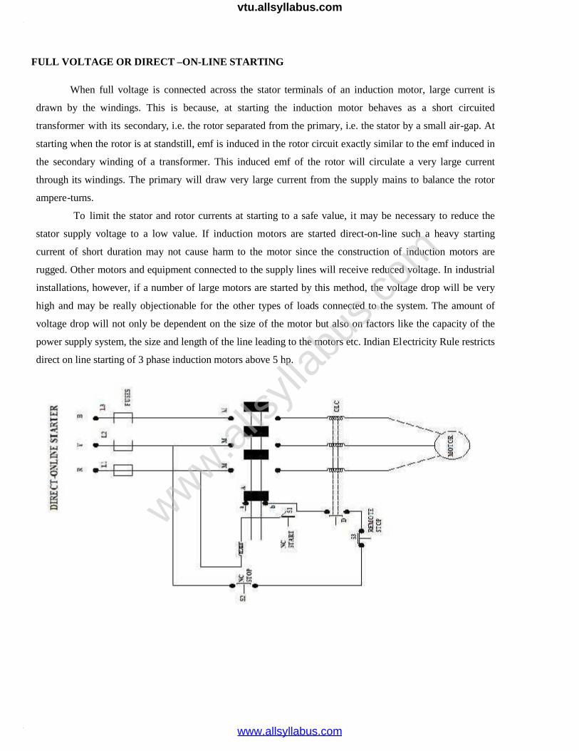
FULL VOLTAGE OR DIRECT –ON-LINE STARTING
When full voltage is connected across the stator terminals of an induction motor, large current is
drawn by the windings. This is because, at starting the induction motor behaves as a short circuited
transformer with its secondary, i.e. the rotor separated from the primary, i.e. the stator by a small air-gap. At
starting when the rotor is at standstill, emf is induced in the rotor circuit exactly similar to the emf induced in
the secondary winding of a transformer. This induced emf of the rotor will circulate a very large current
through its windings. The primary will draw very large current from the supply mains to balance the rotor
ampere-turns.
To limit the stator and rotor currents at starting to a safe value, it may be necessary to reduce the
stator supply voltage to a low value. If induction motors are started direct-on-line such a heavy starting
current of short duration may not cause harm to the motor since the construction of induction motors are
rugged. Other motors and equipment connected to the supply lines will receive reduced voltage. In industrial
installations, however, if a number of large motors are started by this method, the voltage drop will be very
high and may be really objectionable for the other types of loads connected to the system. The amount of
voltage drop will not only be dependent on the size of the motor but also on factors like the capacity of the
power supply system, the size and length of the line leading to the motors etc. Indian Electricity Rule restricts
direct on line starting of 3 phase induction motors above 5 hp.
www.alls
yllab
us.co
m
www.allsyllabus.com
vtu.allsyllabus.com
www.alls
yllab
us.co
m
www.allsyllabus.com
vtu.allsyllabus.com
www.alls
yllab
us.co
m
www.allsyllabus.com
vtu.allsyllabus.com
www.alls
yllab
us.co
m
www.allsyllabus.com
vtu.allsyllabus.com
www.alls
yllab
us.co
m
www.allsyllabus.com
vtu.allsyllabus.com
www.alls
yllab
us.co
m
www.allsyllabus.com
vtu.allsyllabus.com

www.alls
yllab
us.co
m
www.allsyllabus.com
vtu.allsyllabus.com

www.alls
yllab
us.co
m
www.allsyllabus.com
vtu.allsyllabus.com
www.alls
yllab
us.co
m
www.allsyllabus.com
vtu.allsyllabus.com

www.alls
yllab
us.co
m
www.allsyllabus.com
vtu.allsyllabus.com

www.alls
yllab
us.co
m
www.allsyllabus.com
vtu.allsyllabus.com

www.alls
yllab
us.co
m
www.allsyllabus.com
vtu.allsyllabus.com