lab mannual of heat transfer - · pdf filelab mannual of heat transfer (me- 316e) deptt. of...
TRANSCRIPT

LAB MANNUAL
OF
HEAT TRANSFER
(ME- 316E)
DEPTT. OF MECHANICAL ENGINEERING
OM INSTITUTE OF TECHNOLOGY & MANAGEMENT
12km Stone, NH-65, Chandigarh Road Juglan (Hisar) Web Site-www.oitmhisar.com, Email:- [email protected], Ph. No. 01662-264282, Fax-264281,

ME- 316 E HEAT TRANSFER LAB
L T P Credit
--- --- 2 1.0
List of Experiments:
1. To determine the thermal conductivity of a metallic rod.
2. To determine the thermal conductivity of an insulating power.
3. To determine the thermal conductivity of a solid by the guarded hot plate method.
4. To find the effectiveness of a pin fin in a rectangular duct natural convective condition
and plot temperature distribution along its length.
5. To find the effectiveness of a pin fin in a rectangular duct under forced convective and
plot temperature distribution along its length.
6. To determine the surface heat transfer coefficient for a heated vertical tube under natural
convection and plot the variation of local heat transfer coefficient along the length of the
tube. Also compare the results with those of the correlation.
7. To determine average heat transfer coefficient for a externally heated horizontal pipe
under forced convection & plot Reynolds and Nusselt numbers along the length of pipe.
Also compare the results with those of the correlations.
8. To measure the emmisivity of the gray body (plate) at different temperature and plot the
variation of emmisivity with surface temperature.
9. To find overall heat transfer coefficient and effectiveness of a heat exchange under
parallel and counter flow conditions. Also plot the temperature distribution in both the cases
along the length of heat of heat exchanger.
10. To verify the Stefen-Boltzmann constant for thermal radiation.
11. To demonstrate the super thermal conducting heat pipe and compare its working with
that of the best conductor i.e. copper pipe. Also plot temperature variation along the length
with time or three pipes.
12. To study the two phases heat transfer unit.
13. To determine the water side overall heat transfer coefficient on a cross-flow heat
exchanger.
14. Design of Heat exchanger using CAD and verification using thermal analysis package
eg. I-Deas etc.
Note: 1. At least ten experiments are to be performed in the semester.
2. At least seven experiments should be performed from the above list. Remaining three
experiments may either be performed from the above list or designed & set by the
concerned institute as per the scope of the syllabus.
EXPERIMENT NO: 1 Objective: - To find out the thermal conductivity of a given metallic rod. Apparatus Used: -
• Voltmeter • Ammeter • Stop watch • Copper – constantan thermocouple • Power supply • Heating element • Digital temperature indicator • Voltage regulator(Vaiac)
Theory: - Thermal conductivity is an important thermo - physical property of conducting materials, by virtue of which the material conducts the heat energy through it. From Fourier’s law of conduction the thermal conductivity is defined as Q dT dT
k = - ---- ----------- = q ------------ (W/m.K) A dx dx Where,
Q = heat transfer rate, watts, q = heat flux, W /m2 A = area normal to heat transfer, m2, and dT / dx = temperature gradient in the direction of heat flow.
The thermal conductivity for a given material depends on its state and it varies with direction, structure, humidity, pressure and temperature change. Thermal energy can be transported in solids by two means.
1. Lattice vibration, 2. Transport of free electrons.
In good conducting materials, a large number of free electrons move about their lattice structure of metal. These electrons move from higher temperature region to lower temperature region, thus transport heat energy. Further, the increased temperature increases vibration energy of atoms in the lattice structure. Thus in hotter portion of the solid, the atoms which have larger vibration energy, transfer a part of its energy to the neighboring low energy molecules and so on throughout the whole length of the body. Experimental set up with neat Diagram The apparatus consist the heating elements fitted on a table stand. One hole is made in it to accommodate the metal rod whose thermal conductivity has to be measured. The metal rod of brass is inserted into hole so that when power supplied to heater, heat transfer will take place from the base to another end. The temperature of the metal rod is measured at six positions by using copper constantan thermocouples and digital temperature indicator. The power supply to heat may be adjusted to desire quantity by means of electronic controlled circuit for that one rotary switch
is provided on the control panel. Electric power input can be measured by using digital voltmeter and ammeter multiplier. Procedure: -
• Switch on the power supply and adjust voltage and current so as to allow some 500 watts input to heater coil.
• Wait for steady state. Steady state can be observed by the temperature reading at one or all points on the surface of the metal rod. Steady state is reached when these temperatures stop changing with time.
• Under steady state conditions note the temperature of each point on the surface of the rod as well as temperature of surrounding. Repeat above procedure for several power input.
Specifications: -
• Room temperature (T) = --------------------°C • Diameter of the metal rod (d) = ------------ m • Length of the metal rod (L) = ---------------m • Digital voltmeter (0-220) Volt • Digital ammeter (0-2)Amp • Digital temperature indicator (0-300°C) • Thermocouple (copper constantan) • Heating filament (500 watts) • Variac (voltage regulator) (0-2A, 0-230 V, AC supply )
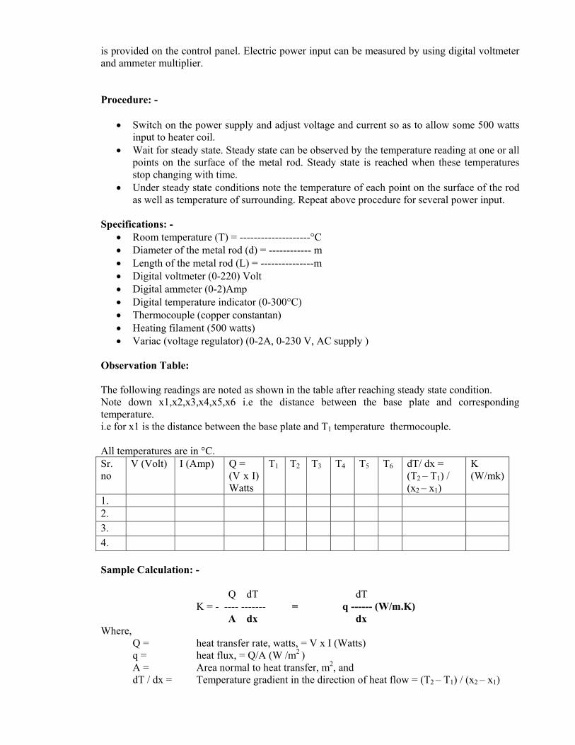
Observation Table: The following readings are noted as shown in the table after reaching steady state condition. Note down x1,x2,x3,x4,x5,x6 i.e the distance between the base plate and corresponding temperature. i.e for x1 is the distance between the base plate and T1 temperature thermocouple. All temperatures are in °C. Sr. no
V (Volt) I (Amp) Q = (V x I) Watts
T1 T2 T3 T4 T5 T6 dT/ dx = (T2 – T1) / (x2 – x1)
K (W/mk)
1. 2. 3. 4. Sample Calculation: - Q dT dT
K = - ---- ------- = q ------ (W/m.K) A dx dx Where,
Q = heat transfer rate, watts, = V x I (Watts) q = heat flux, = Q/A (W /m2 ) A = Area normal to heat transfer, m2, and dT / dx = Temperature gradient in the direction of heat flow = (T2 – T1) / (x2 – x1)
Repeat the experiment 2 to 3 times by changing the power supply and calculate the value of K, each time repeating the procedure outlined above. This will give an idea to the students the effect of temperature on conductivity of the metal rod. Result with conclusion:- Check the calculated value of the given metal (Brass) from standard data book and comment if the calculated value differs from the standard. Take the average of two values of thermal conductivity and put it as out come of the experiment. The average thermal conductivity of the brass = --------- W / m.K
• Compare the value of thermal conductivity obtained by experimentation with standard value. State the reason for deviation, if any.
• From the experiment it is concluded that the temperature goes on decreasing along the length of the rod.
• The thermal conductivity of brass decreases with increases in temperature. This is due to obstruction in flow of free electrons caused due to increase in amplitude of lattice vibration.
Precautions: -
• Wait till perfect steady state is reached. • Input supply must be constant • Handle the change over switch of temperature gently.
Viva Questions
• What is steady-state condition? • What is heat conduction? • What is thermal conductivity? • What is mechanism of heat conduction? • What do you mean by temperature gradient? • What is the purpose of heating element? • State Fourier law? • What is effect of temperature on thermal conductivity of metals?
---------------------------------------------***********-----------------------------------------------

EXPERIMENT NO: 2 Objective: - To study the counter flow and parallel flow heat exchangers and drive the expression for log mean temperature difference and effectiveness. Apparatus :-
• Parallel flow / counter flow heat exchanger.
Theory: - Introduction: - Heat exchanger is a device in which heat is transferred from hot fluid to cold fluid. Heat exchange is process equipment designed for the effective transfer of heat between two fluids a hot fluid and a coolant. The purpose may be either to remove heat from a fluid or to add heat to a fluid. Radiators, evaporators, and condenser are the common example of heat exchangers. Classification of heat exchangers: -
• Direct contact type. • Indirect contact type • Storage type
In direct contact type of heat exchanger, the hot and cold fluids are brought in direct contact. For example is jet condenser, where steam jet and cooling water contact physically for heat exchange. An indirect contact or transfer type heat exchanger is one in which hot fluid and cold fluids are do not make direct contact, but they are separated by a partition wall, acts as heat transfer medium. For example Parallel flow heat exchanger:-In a parallel flow arrangement the fluid (hot or cold) enter the unit form same side, flow in same direction and subsequently leave from same side. Obviously flow of fluids in unidirectional and parallel to each other. Counter flow heat exchanger:-In counter flow arrangement the fluid (hot or cold) enters the unit from opposite ends travels in the opposite direction and subsequently leaves from opposite end. Obviously of liquids is opposite in direction of each other. Cross flow heat exchanger:-Fluid flow at right angle to each other. In storage type or regenerative heat exchanger, hot and cold fluid passes alternately on the same heatv transfer surface for their heat exchange. Log Mean Temperature Difference (LMTD) assumptions:
• The overall heat transfer coefficient ‘U’ is constant throughout the heat exchanger. • The specific heat and mass flow rates of both fluids are constant. This also implies that
heat capacities of fluids are constant over entire length of flow paths. • The exchanger is perfectly insulated and so the heat loss to surroundings is negligible. • The temperature at any cross-section of stream is uniform. • There is no conduction of heat along tubes of heat exchanger. • The K.E and P.E changes are negligible. • The flow conduction is steady.

LMTD Method:- In tabular heat exchanger, the temperature difference between the hot and cold fluids varies with the position in the heat exchanger; therefore it is convenient to determine log mean temperature difference (∆Tm).The total rate between the hot and cold fluids can also be calculated by using overall heat transfer coefficient and surface area as:
Q= UA ∆Tm Where, U = overall heat transfer coefficient, A = surface value of temperature difference. ∆Tm = log mean value of temperature difference. LMTD for the parallel flow heat exchanger: - Consider a parallel flow double pipe heat exchanger as shown in fig. The temperature difference ∆T between hot and cold fluids is large at the inlet of heat exchanger and it decreases exponentially towards the outlet. The temperature of hot fluid decreases and that it decreases exponentially towards the outlet. The temperature of cold fluid can never exceed that of hot fluid in any case. Applying the energy balance to differential elements in hot and cold fluids. The rate of heat transfer dQ from hot fluids dQ = - mh Cp, h dTh----------------------------------------------------------(1) And for cold fluid
dQ = mc Cp, c dTc ------------------------------------------------------------(2) The temperature difference of hot fluid is a negative quantity, and so negative sign is added to eqn. (1) to make the heat transfer rate Q, a positive quantity. Let for differential surface are dA, the temperature difference ∆T between hot and cold fluid is expressed as
∆T = Th – Tc---------------------------------------------------------------------- (3) In differential form:
d (∆T) = dTh - dTc------------------------------------------------------------(4) Solving the equation (1) and equation (2) for dTh and dTc---(5)
dTh = mh Cp, h-------------------------------------------------------------------(6) dTc = mc Cp, c--------------------------------------------------------------------(7)
Substituting the values of dTh and dTc from equation (6) and (7) in equation (4) we get
d (∆T) = - dQ [1 / mh Cp, h + 1 / mc Cp, c]-------------------(8) The heat transfer rate across the differential surface area dA of heat exchanger can also be expressed as
dQ = U∆T dA ----------------------------------------------------------------(9) Using dQ in equation ((8), we get d (∆T) = - U∆T dA [1 / mh Cp, h + 1 / mc Cp, c]--------(10) Rearranging,
d (∆T) / ∆T = - U dA B-------------------------------------------------(11) Integrating equation (11) from inlet to outlet conditions of the heat exchanger.
∆T2
A ∫ d(∆T)/ ∆T = - U B ∫ dA------------------------------------------(12)

∆T1
0
or, ln ∆T2 / ∆T1 = - U B A--------------------------------------------------(13) Substituting B, we get ln ∆T2 / ∆T1 = -U A {1 / mh Cp, h + 1 / mc Cp, c}------(14) Substituting for mh Cp, h and mc Cp, c from equations Q = mh Cp, h (Th, i - Th, o) and Q = mc Cp, c(Tc, o - Tc, i) respectively, we get ln ∆T2 / ∆T1 = -U A { Th, i - Th, o / Q + Tc, o - Tc, I / Q}---(15)
UA or, Q = ln ∆T2 / ∆T1 {( Th, i - Tc, i) – (Th, o - Tc, o)}------------------(16) or, Q A ∆T1 - ∆T2------------------------------------------------------------------------------(17) ln ∆T1 / ∆T2
Comparing above expression with equation Q = UA ∆Tm we get ∆Tm = ∆T1 - ∆T2 = ∆T2 - ∆T1 -----------------------------------------------(18)
ln ∆T1 / ∆T2 ln ∆T2 / ∆T1 The ∆Tlm is called the log mean temperature difference, which is suitable form of temperature difference for tubular heat exchanger. Where ∆T1 and ∆T2 represent the temperature difference between hot and cold fluids at two ends (inlet and outlet) of a heat exchanger. It makes no difference which end of heat exchanger is designed as inlet or outlet. Counter flow heat exchanger is ∆Tlm, counter = (Th, i - Tc, o) – (Th, o - Tc, i) ln [Th, i - Tc, o / Th, o - Tc, i] Viva Questions:-
1. Explain counter flow? 2. Explain parallel flow? 3. What is heat exchanger? 4. What is Nature of heat exchange process? 5. What is Relative direction of motion of fluids? 6. What is Physical state of heat exchanging fluid?
---------------------------------------------***********-----------------------------------------------
EXPERIMENT NO: 03 Objective: - To find out the thermal conductivity of the given insulating powder. Introduction:- Thermal conductivity is one of the important properties of the materials and its knowledge is required for analyzing heat conduction problems. Physical meaning of thermal conductivity is how quickly heat passes through a given material. Thus the determination of this property is of considerable engineering significance.There are various methods of determination of thermal conductivity suitable for finding out thermal conductivity of materials in the powdered form. Apparatus Used: - There are two spherical shells and the insulating material whose conductivity is to be calculated is packed between these two shells. A heating coil is provided in the inner shell. The power is supplied from outside through auto-transformer for heating purpose. A few copper-constantan thermocouples are provided along the radius of the inner and outer spheres, one is fixed on the outer-surface of inner sphere and one is fixed on the outer spheres, one is fixed on the outer-surface of inner sphere and one is fixed on the outer surface of the outer sphere. Sometimes 4 – thermocouples are provided on the inner sphere surface and four are provided on the outer sphere surface for finding the average temperatures on inner and outer sphere surfaces. Theory:- Considering the transfer of heat by heat conduction through the wall of a hollow sphere formed by the insulating powdered layer packed between two thin copper spheres For
ri = inner radius in meters. r0 = outer radius in meters.
Ti = average temperature of the inner surface in °C. T0 = average temperature of the outer surface in °C.
Where, Ti = T1 + T2 + T3 + T4 inner 4
And T0 = T3+T4+T7+T8+T9+T10 outer 6
Note: - That T1 to T10 denote the temperature of thermocouples (1) to (10). Applying the Fourier law of heat conduction for a thin spherical layer of radius r and thickness dr with temperature difference dT the heat transfer rate.
q = -K.4π.r2
dT / dr Kcal / hr ……………..(1) Where, K = thermal conductivity. Separating the variables q / 4π K √dr / r2
= dT …....(2) Integrating (2) in the limits of ri and r0 and T3 and T0 Where,

q / 4π K [ 1 / ri – 1 / ro ] = (Ti – To) q = 4π K ri r0 (Ti – To)…………….(3)
(ro - ri ) From the experimental values of q, I ri and T0 the unknown thermal conductivity K can be determined as:
K = q (ro - ri ) ……………………..(4) 4π ri ro (Ti – To )
Procedure: - • Increases slowly the input to heater by the dimmer stat starting from zero volt position. • Adjust input equal to 40watt max. by voltmeter and ammeter / Wattage (W= V x I) • See that this input remains constant throughout the experiment. • Wait till a satisfactory steady state condition is reached. This can be checked by reading
temperatures of thermocouples (1) to (6) and note changes in their readings with time. • Note down the readings in the observations table as given. Observation Table Inner sphere Thermocouple
no. 1 2 3 4 Mean temperature Ti
Ti = 1 + 2 + 3 + 4 4
Temperature °C
Outer sphere Thermocouple
no. 4 5 6 Mean temperature To
To = 4 + 5 + 6 3
Temperature °C
Specifications:-
• Radius of the inner copper sphere, ri = 120mm • Radius of the outer copper sphere, ro = 200mm • Digital voltmeter 0- 200V red, blue & yellow – mains load – earth • Digital ammeter 0 – 2A • Temperature indicator 0 – 300°C calibrated for copper constantan thermocouple with cold
junction compensation. • Dimmer state 0 – 2A, 0 – 230V, AC • Heater coil: Strip heating element sand witched between mica sheets. • Copper constantan thermocouple.
No. (1) to (3) – embedded on inner sphere to measure Ti. • Copper constantan thermocouple.
No. (4) to (6) – embedded on outer sphere to measure To. • Insulating powder – Asbestos magnesia commercially obtained powder and packed
between the two spheres.

Sample Calculation
A = amps. V = Volts. Ti = °C To = °C ri = inner radius of sphere ro = outer radius of sphere
Result: - Check the calculation value of K with the standard value of the given material (85% magnesia powder) from standard data book and comment if the calculated value differs from the standard. Viva Questions:
1. What is auto transformer? 2. What is the purpose of heating element? 3. Define outer and inner surface?
---------------------------------------------***********-----------------------------------------------

EXPERIMENT NO 04
Objective: To find out the emisssivity of a given gray body.
Introduction: -
All substances have tendency of radiation at all temperatures. Thermal radiation is an electromagnetic behaviour and does not require any medium for propagation. All substances can emit radiation coming from surrounding. An idealized black surface is one which can absorb all the radiation with reflectivity and transmittivity equal to zero. The radiant energy per unit time per unit area from the surface of the body is called emissive power and denoted ‘e’. An emissivity of the surface is the ratio of emissive power of the surface to the emissive power of a black body at the same temperature.
Hence,
Є = + e / e.h
Emmisivity being a property of the surface and depend on the nature of the surface and temperature.
Present experiment setup is designed to measure emmisivity of a surface at various surface temperatures. And material used is aluminum with emmisivity 0.20 to 0.33 at 90 °C to 540°C.
Apparatus used: -
This experimental setup consist of t plates of aluminum, one of them is used as black surface and other as text plate. Both the plates are heated by separate heating element and kept in a closed box which makes undisturbed natural convection surroundings. Power supply to each plate is varied by using dimmer state and measured by a voltmeter and ammeter product. Temperature of plates measured by means of two thermocouples and temperature of ambient is measured by third thermocouple. One plate is blackened by a thick layer of lam black to form idealized black surface while other is used as test plate whose emissivity has to be measured.
Theory: - Under steady state conditions:
Let, q1 = power input to black plate watts = V1 x I1
q2 = power input to test plate watts = V2 x I2
A = Area of the plates = 2 x πd2 / 4 = m2
D = diameter of the plate = 150mm
TB = temperature of black plate °K
TS = temperature of surrounding °K
TP = temperature of test plate °K
Eb = Emissivity of black plate = 1
E = Emissivity of test plate to be find out
= Stephen boltzmans constant = 5.67 x 10⁻⁸ W / m2.K4

Then from Stephen boltzmans equation (q1 – q2) = (Eb) – (E) . A (TB4 – TS
4)
Procedure: -
• Put on power supply and keep both dimmer states at zero initially.
• Increase the power input to black plat to 30 watts and tittles bit less to test plate i. e. 27 watts.
• Check the temperatures of both plates after few minutes. And adjust input of test plate in such a way so that both plates having same temperature. For that trial and error method is used for fair steady state condition.
• After attaining steady state condition note down the temperatures of test plate. Black plate and surrounding and power input.
• Above procedure may be repeated for several electrical power inputs.
Precautions: -
• Always keep dimmer state at zero before starting.
• Increase power input slowly.
• Do not touch black plate.
• Use stabilized electric supply.
Specification: -
• Diameter of black plate = 150mm : material
• Diameter of test plate = 150mm : aluminum
• Heater 4 capacity = 1000 Watts (2 Nos.)
• Dimmer state 0 – 2 Amp. (2 Nos.)
• Ammeter 0 – 2A. 0 – 250 Volts.
• Voltmeter 0 – 250 Volts. 0 – 2A
• Size of enclosure =………….
• Thermocouples – (3 Nos.) copper tungsten’s
• Digital temperature indicator (can measure for 3 digits up to 999 °C.

Observation table: -
Sr. no. Black plate Test plate Ambient temp.
V1 I1 TB V2 I2 TT TS
1
2
3
4
Calculation: - (q1 – q2) = (Eb – E). A (TT 4 – TS4)
Where, q1 = V1 I1 watts
q2 = V2 I2 watts
The emissivity thus may be determined for various heat inputs. And graph may be platted between TT and E.
TT =……. °K
Relation between TT and E.
Result: -
If standard gray body is given, then compare the calculated value with standard value and comment.
Viva Questions
1 What is emisssivity?
2 Why we use gray and black body?
3 Why the power is supplied separately through auto-transfer and watt-meter?
---------------------------------------------***********-----------------------------------------------
EXPERIMENT NO 05
Objective: - To study two phase heat transfer unit to observe the boiling phenomenon & to find out the critical heat flux for the given wire.
Apparatus used: - It consists of a vertical glass beaker, a small electric heater is provided at the bottom and it is connected to the supply directly for initially heating the water. An arrangement for firing a small diameter wire and dipping into water is shown in the fig. This wire is provided with power supply through auto transformer. The boiling is a process of vapour formation from heating surface submerged in the water. During the boiling process, the process passes through natural convection, nucleate boiling and film boiling and ultimately melts if further power supply and ultimately melts if further power supply is increased for increasing surface temperature.
Procedure:
1. Fix the fine wire of know dia. ‘d’ length ‘l’ between two points, then fill the beaker with water, then supply the power to the auxiliary heater till the water starts boiling.
2. Now supply the power to the wire through auto transformer and slowly increase the supply and observe the following region of boiling. Wait for a minute or do at each region of boiling. The following region of boiling will be observed:
(i) At low power supply the dissolved air in water will come out as water as low dissolving capacity for air at temperature. These air bubbles will pass through water and this is not boiling.
(ii) With further increase in power natural current of water starts and moves upwards due to by once force and this indicates natural convection.
(iii) Increasing the power further bubbles are formed on the wire surface and their formation of bubbles is continued and increased in frequency with further increase in power supply.
(iv) With further increase in power supply diameter increases and they re displaced from the surface, then the buoyant force becomes higher than the surface tension and a current of bubbles is formed in the water which strikes the water very rapidly and their process is known as nucleate boiling.
(v) Any further increases in power supply with cause the frequency of bubbles formation more. Then the frequency of bubble displaced from the wire surface. Because of their number wire surface and a film is formed on the wire surface. The thickness of the film increases with time.
(vi) Lastly the continuous flow increases in power supply reaches at a point where wire breaks. As the temperature of wire exceeds its melting point. Note the power supply just before the wire breaks. This is known as critical heat flux passing through wire. The difference phenomenon’s explained above are shown in fig.
∆T = ts – tw
Ts – Wire surface temperature
Tw – Surrounding wire temperature

qc = dc / t1d1
dc – Power supplied to wire just before breaking of liner .
Viva Questions:
1 What is the use of glass beaker?
2 What is vapour formation?
3 What is nucleate boiling?
---------------------------------------------***********-----------------------------------------------

EXPERIMENT NO-06 Objective: - To find out the value of Stephen boltzmann constant and compare the same with the theoretical value. Apparatus: - The round box is a simple water heat tank which is provided with an immersion heater. This tank is connected to another rectangular box by a tube through a tap. The rectangular box is provided with a hemi-spherical shell and inner-surface of hemisphere is blackened with carbon black to make the surface as black body. A small circular disc with minimum weight is fixed at the centre of the hemi-sphere. This is also made a perfect black body by providing carbon-black on the surface. Four thermocouples are provided on the top surface of the hemi-sphere to find surface of the hemi-sphere to fine the average surface temperature. One thermocouple is also fixed at the centre of the disc to measure the temperature of the disk. Procedure: - First heat the water in the heating tank by providing the power and heat the same till water temperature becomes 90°C which is measured by a thermometer fitted in the heating tank. Then pour the water of by opening the tap to the rectangular box till its level is just above the hemi-sphere (A small overflow tube is provided above the height of the hemi-sphere as well as a glass tube is also provided outside to see the height of water in the tank) wait for 5 minute till the hemi-sphere is heated to 80 to 85°C. Observation table:
T1 T2 T3 T4 Times Td 80 81 80 82 0 30 15 38 30 45 45 31 60 56 75 60 90 61 100 65
Important Notes:
1. The hemi-sphere is made of copper with a very thin sheet so that it should be heated earliest possible.
2. The disc is also made of very small diameter and of small thickness as well as of small mass of copper. This helps to increase the temperature rapidly with respect to time (dTd / dt is higher).
3. Only radiation heat transfer between the hemi-sphere and disc is considered and other mode of heat transfer (convection) is neglected.
4. The experiment is carried out under unsteady state condition as the temperature Td is measured with respect to time which is increased.
5. The temperatures T1, T2, T3, and T4 are measured only at t = 0 and then the variations in the temperature Td is only measured with time.
Calculation: - Then draw the graph of time verses Td. At a particular instant (may be t = 0 or t=t1) the heat lost by hemi-sphere must be equal to heat gained by disk. Therefore, σAs (Tm4 – Td4) ЄsFsd = σAd (Tm4 – Td4) ЄdFds Where,
As =2πR2 (hemi-sphere surface area) Єs = Єd = Єb = 1 Td = Temperature of disk at t = or t = 1 Ad πr2 (surface area of disk)
Fds = 1 (As all heat from the surface of disk falls on the hemi-sphere)
Important note: - In equation (2), the values to Tm, Td and (dTd/dt) should be taken at t = 0, because the heat losses in the system and heat transfer by convection between two bodies are minimum as the temperature of disk is lowest as t = 0. Result: - The value of σ calculated will be always less than theoretical as all heat losses cannot be neglected and there will be some heat transfer between the two bodies by convection which is neglected in the calculations.
Viva Question
1 Why water is heated before starting the experiment?
2 What is the function of glass tube?
3 Why a black body is providing (carbon-black) on the surface?
---------------------------------------------***********-----------------------------------------------

EXPERIMENT NO. 07
Objective: - To find out the thermal conductivity of two slab guarded by hot plate method. Principle: - A sketch of the apparatus is shown in fig. no (1). The essential parts are the hot plate, the cold plate, the heater assembly, thermocouples and the specimens in position are shown in the same fig. For the measurement of thermal conductivity (K) what is required is to have a one dimensional heat flow through the flat specimen, an arrangement for maintaining its faces at constant temperature and some metering method to measure the heat flow through a known area. To eliminate the distortion caused by edge losses in unidirectional heat flow, the central plate is surrounded by a guard ring which is separately heated. Temperatures are measured by calibrated thermocouples either attached to the plates or to the specimens at the hot and cold faces. Two specimens are used to unsure that all the heat comes out through the specimen only. Knowing the heat input to the central plate heater, the temperature difference across the specimen. Its thickness and the metering are. One can calculate K of the specimen by the following formula:
K = Q / A (L / Th – Tc) Kcat / hr – m - °C
Where, Th = temperature of hot plate i.e. (T1 + T2) /2 in °C Tc = temperature of cold plate i.e (T5 + T6) /2 in °C K = thermal conductivity of sample Kcal / hr – m - °C q = Heat flow rate in the specimen. Kcal / hr A = metering area of the specimen. m2
L = thickness of specimen. m. 12.3mm
If the specimen thickness are different and the respective hot and cold temperatures are different then K = q / A [ t / (Th1 – Tc1) / L1 + t / (Th1 – Tc1) / L2 Where suffifix 1 is the upper specimen and 2 lower specimens. Apparatus: - This apparatus is designed and fabricated with IS: 3346 – 1966 as a guide line. Having the following specification: Specifications: Diameter of the heating plate = 90mm Width of heating ring = 5mm Inside diameter of the heating ring = 95mm Outside diameter of the heating ring = 120mm Maximum thickness of the specimen = 25mm Minimum thickness of the specimen = 6mm Diameter of the specimen = 120 Mean temperature range 40°C to 100°C = max. Voltage = 150V Maximum temperature of the hot plate = 100°C max. Current = 1.5A Diameter of the cooling plates = 120mm Central heater: Nichrome strip type sand witched between mica sheets. Guarded Heat Ring:

Nichrome strip type sand witched between mica sheets. Dimmer state – 2 nos. 0-2 Amp. 0-240Volts Voltmeter = 0 – 100 V Ammeter = 0 – 2A Thermocouples: 6 nos. copper constantan. Insulation box 375mm x 375mm x 275mm (approx.) Temperature indicator = 0 - 200°C Description: - Outer heater having high temperature heat flow from high to low, so if outer heater temperature is high heat then inner heat will not flow in this direction thus ensures unidirectional heat flow. The heater plate is surrounded by a heating ring for stabilizing. The temperature of the primary heat and prevent heat loss radially around its edges. The primary and guard heater are made up of mica sheets in which is wound closely spaced Nichrome wire and packed with upper and lower mica sheets. These heaters together from a flat which together with upper and lower copper plates and rings form the heater plate assembly. Two thermocouples are used to measure the hot face temperature at the upper and lower central heater assembly copper plates. Two more thermocouples are used to check balance in both the heater input. Specimen is held between the heater and cooling unit on each side of the apparatus. Thermocouple no 5 and 6 measures the temperature of the upper cooling plate and lower cooling plate respectively. Procedure: - • The specimens are placed on either side of the heating plate assembly. Uniformly touching the
cooling plates. Then the outer container is fitted with loose fill insulation such as glass wool supplied in small cloth packets.
• The cooling circuit is started then calculated input is given to central and guard heaters through separate single phase supply lines with a dimmer state in each line desired temperature.
• The guard heater input is adjusted in such a way that there is no radial heat flow which is checked from thermocouple readings and is adjusted accordingly. The input to the central heater (current and voltage or watts) and the thermouple readings are recorded every 10 minutes till a reasonably steady state condition is reached. The readings are recorded in the observation table.
• The final steady state values are taken for calculations. Precautions: - • Do not exceed power input to heaters more than 100 watts. • Keep dimmer state to zero voltage position before start. • Increase the voltage gradually. • Start the cooling circuit before switching on the heaters and adjust the flow rate so that
practically there is no temperature rise in the circulation fluid. • Keep the heater plate undisturbed and adjust the cooling plates after keeping the samples with
the help of nuts gently. • Keep the loose fill insulation (glass wool) packets gently and remove them slowly so that they
do not disturb the thermocouples terminals and heater wires. Instructions: - • For ensuring that no radial heat transfer is there. Generally outer heater input is about 2.5 to 3
times then central heating input. Specification: - • Central heater input (Inner heater) = V1 x T1 = W1 • Guard heater input (outer heater) = V2 x T2 W2
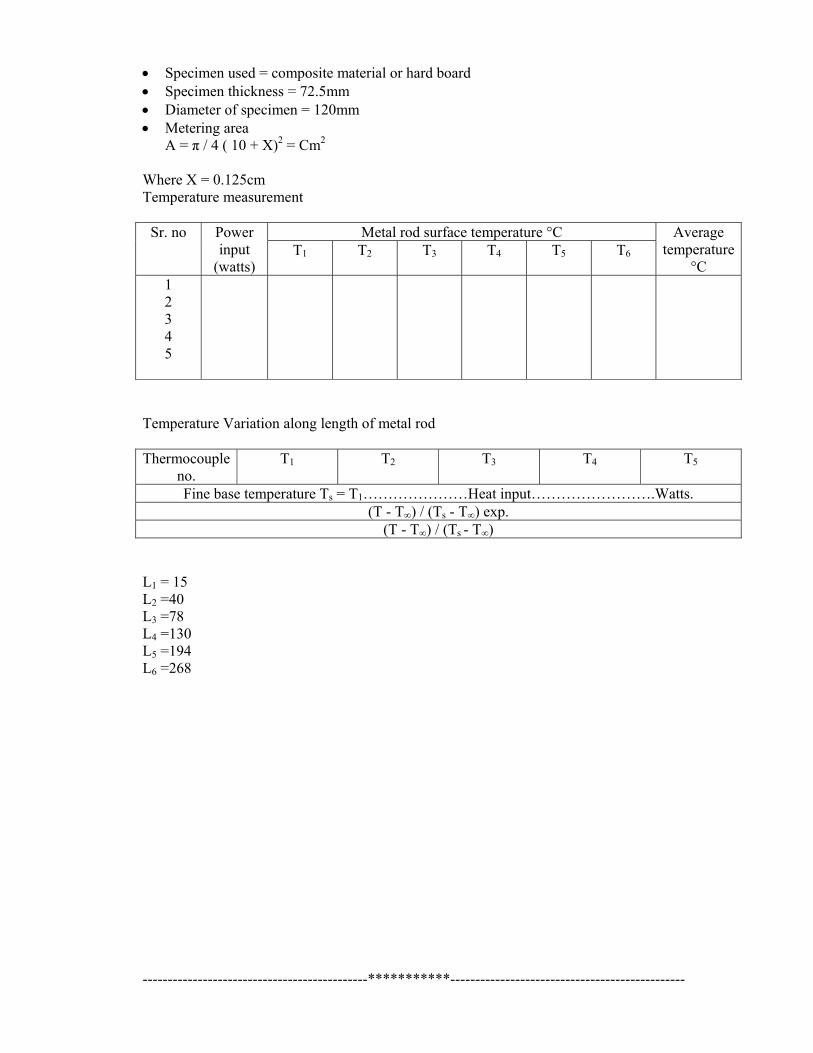
• Specimen used = composite material or hard board • Specimen thickness = 72.5mm • Diameter of specimen = 120mm • Metering area
A = π / 4 ( 10 + X)2 = Cm2
Where X = 0.125cm Temperature measurement
Sr. no Power input
(watts)
Metal rod surface temperature °C Average temperature
°C T1 T2 T3 T4 T5 T6
1 2 3 4 5
Temperature Variation along length of metal rod Thermocouple
no. T1 T2 T3 T4 T5
Fine base temperature Ts = T1…………………Heat input…………………….Watts. (T - T∞) / (Ts - T∞) exp.
(T - T∞) / (Ts - T∞) L1 = 15 L2 =40 L3 =78 L4 =130 L5 =194 L6 =268 ---------------------------------------------***********-----------------------------------------------
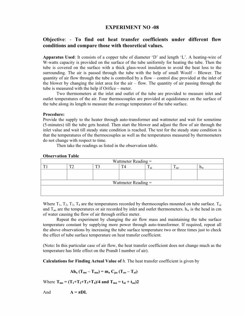
EXPERIMENT NO -08
Objective: - To find out heat transfer coefficients under different flow conditions and compare those with theoretical values. Apparatus Used: It consists of a copper tube of diameter ‘D’ and length ‘L’. A heating-wire of W-watts capacity is provided on the surface of the tube uniformly for heating the tube. Then the tube is covered on the surface with a thick glass-wool insulation to avoid the heat loss to the surrounding. The air is passed through the tube with the help of small Woolf – Blower. The quantity of air flow through the tube is controlled by a flow – control disc provided at the inlet of the blower by changing the inlet area for the air – flow. The quantity of air passing through the tube is measured with the help if Orifice – meter. Two thermometers at the inlet and outlet of the tube are provided to measure inlet and outlet temperatures of the air. Four thermocouples are provided at equidistance on the surface of the tube along its length to measure the average temperature of the tube surface. Procedure: Provide the supply to the heater through auto-transformer and wattmeter and wait for sometime (5-minutes) till the tube gets heated. Then start the blower and adjust the flow of air through the inlet value and wait till steady state condition is reached. The test for the steady state condition is that the temperatures of the thermocouples as well as the temperatures measured by thermometers do not change with respect to time. Then take the readings as listed in the observation table. Observation Table
Wattmeter Reading = T1 T2 T3 T4 Tai Tao hw
Wattmeter Reading = Where T1, T2, T3, T4 are the temperatures recorded by thermocouples mounted on tube surface. Tai and Tao are the temperatures or air recorded by inlet and outlet thermometers. hw is the head in cm of water causing the flow of air through orifice meter. Repeat the experiment by changing the air flow mass and maintaining the tube surface temperature constant by supplying more power through auto-transformer. If required, repeat all the above observations by increasing the tube surface temperature two or three times just to check the effect of tube surface temperature on heat transfer coefficient. (Note: In this particular case of air flow, the heat transfer coefficient does not change much as the temperature has little effect on the Prandt l number of air). Calculations for Finding Actual Value of h. The heat transfer coefficient is given by
Aha (Tms – Tma) = ma Cpa (Tao – Tai)
Where Tms = (T1+T2+T3+T4)/4 and Tma = tai + tao)2 And A = πDL

ma and Cpa are the mass of air flowing through the tube and specific heat of air . The mass of air passing through the tube is given by ma = CdAc √2g. hw/100 x ρw/ρa x ρa (kg/sec.) Where
Cd = Coefficient of discharge of orifice meter (given) Aco = Cross-sectional area of the orifice meter
=π/4d2 (d is the diameter of orifice) ρw and ρa = are the densities of water and air.
Now in the equation (1), all the parameters are known except ha, so find out the value of ha. The value of ha can be calculated for different air-mass flow (for 3 to 4 minutes). Calculation Table:
Wattmeter Reading = Practical Calculations Theoretical Calculations
V (Velocity of air through
tube
ha (W/m2-K) Re Pr Ht (W/m2-K)
Result: - Now draw the graph Re verses h for practical and theoretical calculations. It is obvious from the graph the value of ha is less then ht and that is because of unaccounted losses in the experiment. The value h (actual and theoretical) has some value even there is no air flow (Re = 0). This is because, even in the absence of flow, there is always natural convection when the tube temperature is higher than the stagnant air temperature in the tube. Viva Questions:
1 What is Orifice – meter? 2 What is the function of blower in the experiment? 3 What is the effect of air flow in experiment?
---------------------------------------------***********-----------------------------------------------

EXPERIMENT NO: 09 Objective: - To find out the efficiency of pin fin in natural convection conditions. Theory: - A fin of brass (iron or copper) of circular cross-section (square or triangular) or length L is fitted in rectangular duct. One end of the fin which is projected outside duct is provided with a heater for heating the fin. Five thermocouples are provided on the surface of the fin at equal distances. The duct is provided with a blower to control the air flow with the help of valve. Apparatus Used: - A pin fin is screwed to a cylindrical heating pipe making the test section. The test section is kept in a rectangular duct, which is open of both ends for natural air flow. One acrylic sheet is also fitted in the duct so as to see the duct and test section. When electric current input and the test-section, heat transfer takes place from cylinder to pin fin, the temperature of fin can be measured by digital temperature indicator with the help of copper – constant thermocouples. Five thermocouples are embedded on pin fin at intervals of 25mm. One thermocouple is used to measure surrounding temperature of the duct. Procedure: -
• Switch on the power supply to control panel. • Increase power input to heating cylinder by means of dimmer state to desired heat input. • Wait till steady state condition reaches. • Take the readings of parameters required for calculations. • Repeat above for various heat input, say 50 watts, 100 watts and 150 watts.
Observation Table Steady state fin temperature for electric input of -------------W
SI. no.
Distance from base of fin x L
mm
Temperature along length of fin TS Average temperature T8 T9 T10 T11 T12
1 2 3 4 5 6
Fin length = 150mm Diameter = 5 mm Room temperature = T∞ – T7 °C Metal brass K = ? h = given P = peripheri A = Area Calculation: Distance base of fin x = 150mm Temperature at x.T = °C From graph of X averages I = Fin base temperature TS = °C

Temperature grain [ dt / dx] x = 0 Hence, T1 - T∞ / T5 - T∞ Calculation of result: q = KAm (ts - T∞) tan h m.L m = √h.p./KA Fin efficiency (η) = (tan h m.L) / m.L Result: With the help of calculation table draw the following graph.
1. h, verses temperature distribution for practical values and theoretical values. 2. h, verses Є and η for natural convection and forced convection.
In all the cases T0 is maintained constant for natural and forced convection by varying the power P Viva Questions
1 What is Natural convection? 2 What is Forced convection? 3 Explain the orifice meter?
---------------------------------------------***********-----------------------------------------------
EXPERIMENT NO: 10 Objective: - To determine the thermal conductivity of metal by method of heat transfer in extended surface. Apparatus Used: -Thermal conductivity of metal apparatus Theory: - If Q1 is the power required to be supplied to heating sources for maintaining any steady temperature at vertical and surface. When one kind of metal is inserting into heating source and Q2 electric power require maintaining same steady state. Then heat transfer from metal roll can be given by θ = Q1 – Q2 Here it is assumed that metal rod has a particular length and no heat transfer from end and no heat transfer from ends. Again Q = √h.P.K.A (TS – T0) tan (m.L.) = Q1 – Q2 But infinite length of fin L = 310mm The thermal conductivity K can be determined from above equation if h is known for the value of h table provided may be used. Fluid temperature distribution along length of metal rod may be calculated known equation.
t0 – t / t0 – tp = emm / 1+e2me + e-mm / 1+e2ml = cos h (L-H) / cos h (ml)
Description: - The apparatus consists one heating element fitted on a table stable. One hole is made in it to accommodate the metal rod. The metal rod of brass is inserted into hole so that when power is supplied to heater, heat transfer will take place from base to another end. The temperature of metal rod is measured at fine position by using temperature of thermocouple and digital temperature indicator power supply is heat may be adjusted to desire quantity by means of electronic controlled circuit for that one rotary switch is provided on control panel. Electrical power input can be measured by using digital voltmeter and ammeter multiplier. Procedure: -
• Switch on the power supply and adjust voltage and current so as to allow some 500 watts input to heater coil.
• Wait for steady state. Steady state can be observed by the temperature reading at one or all points on the surface of the metal rod. Steady state is reached when these temperatures stop changing with time.
• Under steady state conditions note the temperature at each point on the surface of the rod as well as temperature of surrounding (room temperature). Repeat above for several power inputs.
Specifications: -
• Room temperature T = …………..°C • Diameter of the metal rod = ………. • Length of the metal rod = …………. • Digital Voltmeter 0 – 220V • Digital ammeter 0 – 2A • Temperature indicator 0 – 300°C calibrated for copper constant thermocouples with cold
junction compensation. • Dimmer state 0 – 2A, 0 – 230V, AC

• Heater 500Watts. Viva Questions:
1. Explain thermal conductivity? 2. Explain the method of heat transfer in extend surface? 3. What is the purpose of thermocouples?
---------------------------------------------***********-----------------------------------------------