lab 9.2.4 ip addressing basics · this lab exercise helps develop an understanding of ip addresses...
TRANSCRIPT

Lab 9.2.4 IP Addressing Basics
Objective • Name the five different classes of IP addresses
• Describe the characteristics and use of the different IP address classes
• Identify the class of an IP address based on the network number
• Determine which part, or octet, of an IP address is the network ID and which part is the host ID
• Identify valid and invalid IP host addresses based on the rules of IP addressing
• Define the range of addresses and default subnet mask for each class
Background / Preparation This lab exercise helps develop an understanding of IP addresses and how TCP/IP networks operate. It is primarily a written lab exercise. However, it would be worthwhile to review some real network IP addresses using the command line utilities ipconfig for Windows NT/2000/XP or winipcfg for Windows 9x/ME. IP addresses are used to uniquely identify individual TCP/IP networks and hosts, such as computers and printers, on those networks in order for devices to communicate. Workstations and servers on a TCP/IP network are called hosts and each has a unique IP address. This address is referred to as its host address. TCP/IP is the most widely used protocol in the world. The Internet or World Wide Web only uses IP addressing. In order for a host to access the Internet, it must have an IP address.
In its basic form, the IP address has two parts:
• A network address
• A host address
The network portion of the IP address is assigned to a company or organization by the Internet Network Information Center (InterNIC). Routers use the IP address to move data packets between networks. IP addresses are 32 bits long according to the current version IPv4 and are divided into 4 octets of 8 bits each. They operate at the network layer (Layer 3) of the Open System Interconnection (OSI) model, which is the Internet layer of the TCP/IP model. IP addresses are assigned in the following ways:
• Statically – manually, by a network administrator
• Dynamically – automatically, by a Dynamic Host Configuration Protocol (DHCP) server
The IP address of a workstation, or host is a logical address, meaning it can be changed. The Media Access Control (MAC) address of the workstation is a 48-bit physical address. This address is burned into the network interface card (NIC) and cannot change unless the NIC is replaced. The combination of the logical IP address and the physical MAC address helps route packets to their proper destination.
There are five different classes of IP addresses, and depending on the class, the network and host part of the address will use a different number of bits. In this lab, different classes of IP addresses will be worked with and to help become familiar with the characteristics of each. The understanding of IP addresses is critical to the understanding of TCP/IP and internetworks in general. The following resources are required:
1 - 4 CCNA 1: Networking Basics v 3.0 - Lab 9.2.4 Copyright 2003, Cisco Systems, Inc.

• PC workstation with Windows 9x/NT/2000/XP installed
• Access to the Windows Calculator
Step 1: Review IP address classes and their characteristics Address classes There are five classes of IP addresses, A through E. Only the first three classes are used commercially. A Class A network address is discussed in the table to get started. The first column is the class of IP address. The second column is the first octet, which must fall within the range shown for a given class of addresses. The Class A address must start with a number between 1 and 126. The first bit of a Class A address is always a zero, meaning the High Order Bit (HOB) or the 128 bit cannot be used. 127 is reserved for loopback testing. The first octet alone defines the network ID for a Class A network address.
Default subnet mask The default subnet mask uses all binary ones, decimal 255, to mask the first 8 bits of the Class A address. The default subnet mask helps routers and hosts determine if the destination host is on this network or another one. Because there are only 126 Class A networks, the remaining 24 bits, or 3 octets, can be used for hosts. Each Class A network can have 224, or over 16 million hosts. It is common to subdivide the network into smaller groupings called subnets by using a custom subnet mask, which is discussed in the next lab.
Network and host address The network or host portion of the address cannot be all ones or all zeros. As an example, the Class A address of 118.0.0.5 is a valid IP address. The network portion, or first 8 bits, which are equal to 118, is not all zeros and the host portion, or last 24 bits, is not all zeros or all ones. If the host portion were all zeros, it would be the network address itself. If the host portion were all ones, it would be a broadcast for the network address. The value of any octet can never be greater than decimal 255 or binary 11111111.
Class 1st Octet Decimal Range
1st Octet High Order Bits
Network/Host ID (N=Network, H=Host)
Default Subnet Mask
Number of Networks
Hosts per Network (Usable Addresses)
A 1 – 126 * 0 N.H.H.H 255.0.0.0 126 (27 – 2) 16,777,214 (224 – 2)
B 128 – 191 10 N.N.H.H 255.255.0.0 16,382 (214 – 2)
65,534 (216 – 2)
C 192 – 223 110 N.N.N.H 255.255.255.0 2,097,150 (221 – 2)
254 (28 – 2)
D 224 – 239 1110 Reserved for Multicasting
E 240 – 254 11110 Experimental; used for research
Note: Class A address 127 cannot be used and is reserved for loopback and diagnostic functions.
2 - 4 CCNA 1: Networking Basics v 3.0 - Lab 9.2.4 Copyright 2003, Cisco Systems, Inc.

Step 2: Determine basic IP addressing Use the IP address chart and your knowledge of IP address classes to answer the following questions:
1. What is the decimal and binary range of the first octet of all possible Class B IP addresses?
Decimal: From: ________ To: ________
Binary: From: ________ To: ________
2. Which octet(s) represent the network portion of a Class C IP address? ___________________
3. Which octet(s) represent the host portion of a Class A IP address? ______________________
4. What is the maximum number of useable hosts with a Class C network address? ___________
5. How many Class B networks are there? ___________________
6. How many hosts can each Class B network have? __________________________
7. How many octets are there in an IP address? ________How many bits per octet? __________
Step 3: Determine the host and network portions of the IP address With the following IP host addresses, indicate the following:
• Class of each address
• Network address or ID
• Host portion
• Broadcast address for this network
• Default subnet mask
The host portion will be all zeros for the network ID. Enter just the octets that make up the host. The host portion will be all ones for a broadcast. The network portion of the address will be all ones for the subnet mask. Fill in the following table:
Host IP Address Address Class
Network Address
Host Address
Network Broadcast Address
Default Subnet Mask
216.14.55.137
123.1.1.15
150.127.221.244
194.125.35.199
175.12.239.244
Step 4: Given an IP address of 142.226.0.15 and a subnet mask of 255.255.255.0, answer the following questions:
What is the binary equivalent of the second octet? _____________________________________
What is the class of the address? _________________________________________________
What is the network address of this IP address? ______________________________________
3 - 4 CCNA 1: Networking Basics v 3.0 - Lab 9.2.4 Copyright 2003, Cisco Systems, Inc.

Is this a valid IP host address (Y/N)? ______________________________________________
Why or why not?
__________________________________________________________________________
__________________________________________________________________________
__________________________________________________________________________
Step 5: Determine which IP host addresses are valid for commercial networks For the following IP host addresses, determine which are valid for commercial networks and indicate why or why not. Valid means it could be assigned to any of the following:
• Workstation
• Server
• Printer
• Router interface
• Any other compatible device
Fill in the following table:
IP Host Address Valid Address? (Yes/No)
Why or Why Not
150.100.255.255
175.100.255.18
195.234.253.0
100.0.0.23
188.258.221.176
127.34.25.189
224.156.217.73
4 - 4 CCNA 1: Networking Basics v 3.0 - Lab 9.2.4 Copyright 2003, Cisco Systems, Inc.

Lab 10.3.5a Basic Subnetting
Objective • How to identify reasons to use a subnet mask
• How to distinguish between a default subnet mask and a custom subnet mask
• What given requirements determine the subnet mask, number of subnets, and hosts per subnet
• What needs to be understood about useable subnets and useable numbers of hosts
• How to use the ANDing process to determine if a destination IP address is local or remote
• How to identify valid and invalid IP host addresses based on a network number and subnet mask
Background / Preparation This lab exercise focuses on the basics of IP subnet masks and their use with TCP/IP networks. The subnet mask can be used to split up an existing network into subnetworks, or subnets. Some of the primary reasons for subnetting are the following:
• Reduce the size of the broadcast domains, which creates smaller networks with less traffic
• Allow LANs in different geographical locations to communicate through routers
• Provide improved security by separating one LAN from another
Routers separate subnets, and determine when a packet can go from one subnet to another. Each router a packet goes through is considered a hop. Subnet masks help workstations, servers, and routers in an IP network determine if the destination host for the packet they want to send is on their own network or another network. This lab reviews the default subnet mask and then focuses on custom subnet masks. Custom subnet masks use more bits than the default subnet masks by borrowing these bits from the host portion of the IP address. This creates a three-part address:
• The original network address
• The subnet address made up of the bits borrowed
• The host address made up of the bits left after borrowing some for subnets
Step 1 Review the structure of IP addresses If an organization has a Class A IP network address, the first octet, or 8 bits, is assigned and does not change. The organization can use the remaining 24 bits to define up to 16,777,214 hosts on its network. This is a lot of hosts. It is not possible to put all of these hosts on one physical network without separating them with routers and subnets.
It is common for a workstation to be on one network or subnet and a server to be on another. When the workstation needs to retrieve a file from the server it will need to use its subnet mask to determine the network or subnet that the server is on. The purpose of a subnet mask is to help hosts and routers determine the network location where a destination host can be found. Refer to the table below to review the following information:
• The IP address classes
• The default subnet masks
1 - 7 CCNA 1: Networking Basics v 3.0 – Lab10.3.5a Copyright 2003, Cisco Systems, Inc.
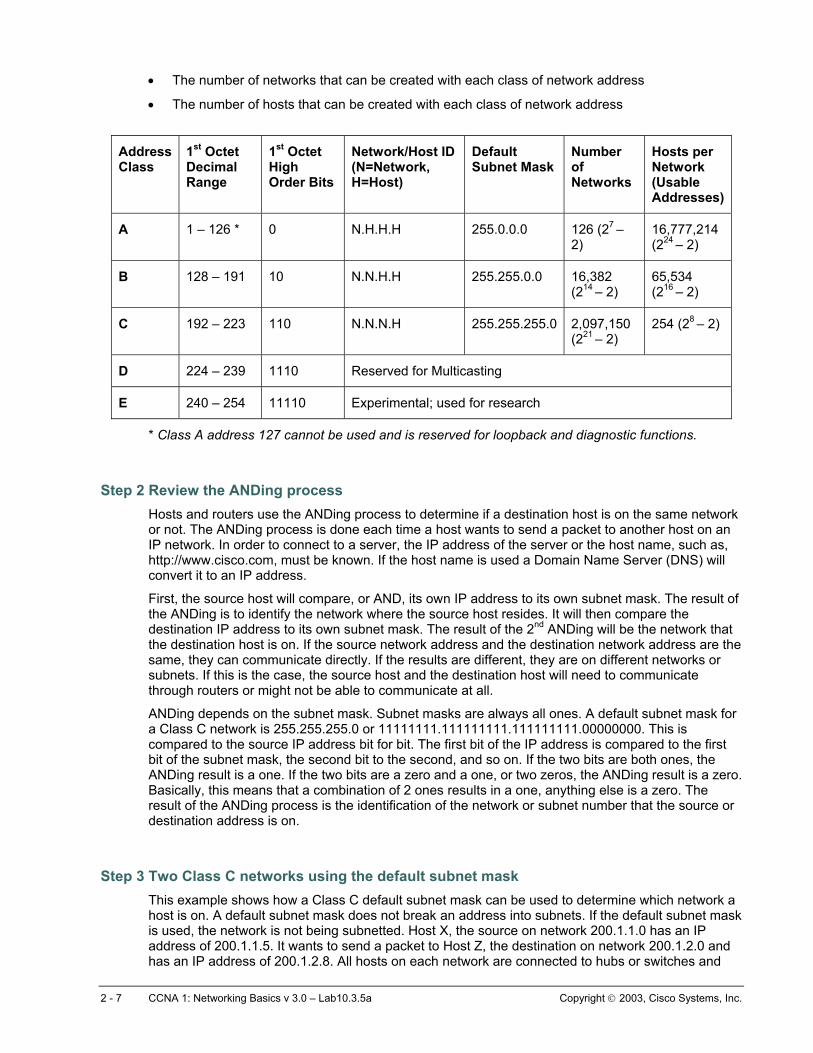
• The number of networks that can be created with each class of network address
• The number of hosts that can be created with each class of network address
Address Class
1st Octet Decimal Range
1st Octet High Order Bits
Network/Host ID (N=Network, H=Host)
Default Subnet Mask
Number of Networks
Hosts per Network (Usable Addresses)
A 1 – 126 * 0 N.H.H.H 255.0.0.0 126 (27 – 2)
16,777,214 (224 – 2)
B 128 – 191 10 N.N.H.H 255.255.0.0 16,382 (214 – 2)
65,534 (216 – 2)
C 192 – 223 110 N.N.N.H 255.255.255.0 2,097,150 (221 – 2)
254 (28 – 2)
D 224 – 239 1110 Reserved for Multicasting
E 240 – 254 11110 Experimental; used for research
* Class A address 127 cannot be used and is reserved for loopback and diagnostic functions.
Step 2 Review the ANDing process Hosts and routers use the ANDing process to determine if a destination host is on the same network or not. The ANDing process is done each time a host wants to send a packet to another host on an IP network. In order to connect to a server, the IP address of the server or the host name, such as, http://www.cisco.com, must be known. If the host name is used a Domain Name Server (DNS) will convert it to an IP address.
First, the source host will compare, or AND, its own IP address to its own subnet mask. The result of the ANDing is to identify the network where the source host resides. It will then compare the destination IP address to its own subnet mask. The result of the 2nd ANDing will be the network that the destination host is on. If the source network address and the destination network address are the same, they can communicate directly. If the results are different, they are on different networks or subnets. If this is the case, the source host and the destination host will need to communicate through routers or might not be able to communicate at all.
ANDing depends on the subnet mask. Subnet masks are always all ones. A default subnet mask for a Class C network is 255.255.255.0 or 11111111.111111111.111111111.00000000. This is compared to the source IP address bit for bit. The first bit of the IP address is compared to the first bit of the subnet mask, the second bit to the second, and so on. If the two bits are both ones, the ANDing result is a one. If the two bits are a zero and a one, or two zeros, the ANDing result is a zero. Basically, this means that a combination of 2 ones results in a one, anything else is a zero. The result of the ANDing process is the identification of the network or subnet number that the source or destination address is on.
Step 3 Two Class C networks using the default subnet mask This example shows how a Class C default subnet mask can be used to determine which network a host is on. A default subnet mask does not break an address into subnets. If the default subnet mask is used, the network is not being subnetted. Host X, the source on network 200.1.1.0 has an IP address of 200.1.1.5. It wants to send a packet to Host Z, the destination on network 200.1.2.0 and has an IP address of 200.1.2.8. All hosts on each network are connected to hubs or switches and
2 - 7 CCNA 1: Networking Basics v 3.0 – Lab10.3.5a Copyright 2003, Cisco Systems, Inc.

then to a router. Remember that with a Class C network address, the first 3 octets, or 24 bits, are assigned as the network address. So, these are two different Class C networks. This leaves one octet, or 8 bits for hosts, so each Class C network could have up to 254 hosts:
• 28 = 256 – 2 = 254
Source net: 200.1.1.0 Destination net: 200.1.2.0 Subnet mask: 255.255.255.0 Subnet mask: 255.255.255.0
Host IP 200.1.1.5 Host 200.1.2.8
Hub
Hub Router
Host Z
Host X
Router interface Router interface IP 200.1.1.1 IP 200.1.2.1
The ANDing process helps the packet get from Host 200.1.1.5 on network 200.1.1.0 to Host 200.1.2.8 on network 200.1.2.0 by using the following steps:
1. Host X compares its own IP address to its own subnet mask using the ANDing process.
Host X IP address 200.1.1.5 11001000.00000001.00000001.00000101
Subnet Mask 255.255.255.0 11111111.11111111.11111111.00000000
ANDing Result (200.1.1.0) 11001000.00000001.00000001.00000000
Note: The result of the ANDing process is the network address of Host X, which is 200.1.1.0.
2. Next, Host X compares the IP address of the Host Z destination to its own subnet mask using the ANDing process.
Host Z IP address 200.1.2.8 11001000.00000001.00000010.00001000
Subnet Mask 255.255.255.0 11111111.11111111.11111111.00000000
ANDing Result (200.1.2.0) 11001000.00000001.00000010.00000000
Note: The result of the ANDing process is the network address of Host Z, which is 200.1.2.0.
Host X compares the ANDing results from Step 1 and the ANDing results from Step 2, and notes they are different. Host X now knows that Host Z is not in its local-area network (LAN). Therefore, it must send the packet to its default gateway, which is the IP address of the router interface of 200.1.1.1 on network 200.1.1.0. The router then repeats the ANDing process to determine which router interface to send the packet out to.
3 - 7 CCNA 1: Networking Basics v 3.0 – Lab10.3.5a Copyright 2003, Cisco Systems, Inc.

Step 4 One Class C network with subnets using a custom subnet mask This example uses a single Class C network address (200.1.1.0) and shows how a Class C custom subnet mask can be used to determine which subnetwork (or subnet) a host is on and to route packets from one subnetwork to another. Remember that with a Class C network address, the first 3 octets, or 24 bits are assigned as the network address. This leaves one octet, or 8 bits, for hosts. So, each Class C network could have up to 254 hosts:
• 28 = 256 – 2 = 254
Perhaps less than 254 hosts, workstations and servers combined, are desired on one network. This could be for security reasons or to reduce traffic. It can be done by creating two subnetworks and separating them with a router. This will create smaller independent broadcast domains and can improve network performance and increase security. This is possible because these subnetworks will be separated by one or more router. Assume at least two subnetworks will be needed and that there will be at least 50 hosts per subnetwork. Because there is only one Class C network address, only 8 bits in the fourth octet are available for a total of 254 possible hosts. Therefore, a custom subnet mask must be created. The custom subnet mask will be used to borrow bits from the host portion of the address. The following steps help accomplish this:
1. The first step to subnetting is to determine how many subnets are needed. In this case, its two subnetworks. To see how many bits should be borrowed from the host portion of the network address, add the bit values from right to left until the total is equal to or greater than the number of subnets needed. Because two subnets are needed, add the one bit and the two bit, which equals three. This is greater than the number of subnets needed. To remedy this, borrow at least two bits from the host address starting from the left side of the octet that contains the host address.
Network address: 200.1.1.0 4th octet Host address bits: 1 1 1 1 1 1 1 1
Host address bit values 128 64 32 16 8 4 2 1 (from right)
Add bits starting from the right side, the 1 and the 2, until the sum is greater than the number of subnets needed.
Note: An alternate way to calculate the number bits to be borrowed for subnets is to take the number of bits borrowed to the power of 2. The result must be greater than the number of subnets needed. As an example if 2 bits are borrowed the calculation is two to the second power, which equals four. Since the number of subnets needed is two this should be adequate.
2. After we know how many bits to borrow, we take them from the left side of the of the host address, the 4th octet. Every bit borrowed from the host address bit leaves fewer bits for the hosts. Even though the number of subnets is increased, the number of hosts per subnet is decreased. Because two bits need to be borrowed from the left side, that new value must be shown in the subnet mask. The existing default subnet mask was 255.255.255.0 and the new custom subnet mask is 255.255.255.192. The 192 results from adding the first two bits from the left, 128 + 64 = 192. These bits now become 1s and are part of the overall subnet mask. This leaves 6 bits for host IP addresses or 26 = 64 hosts per subnet.
4th Octet borrowed bits for subnet: 1 1 0 0 0 0 0 0
Subnet bit values: (from left side) 128 64 32 16 8 4 2 1
With this information, the following table can be built. The first two bits are the subnet binary value.
The last 6 bits are the host bits. By borrowing 2 bits from the 8 bits of the host address 4 subnets,
2^2, with 64 hosts each, can be created. The 4 networks created are as follows:
4 - 7 CCNA 1: Networking Basics v 3.0 – Lab10.3.5a Copyright 2003, Cisco Systems, Inc.
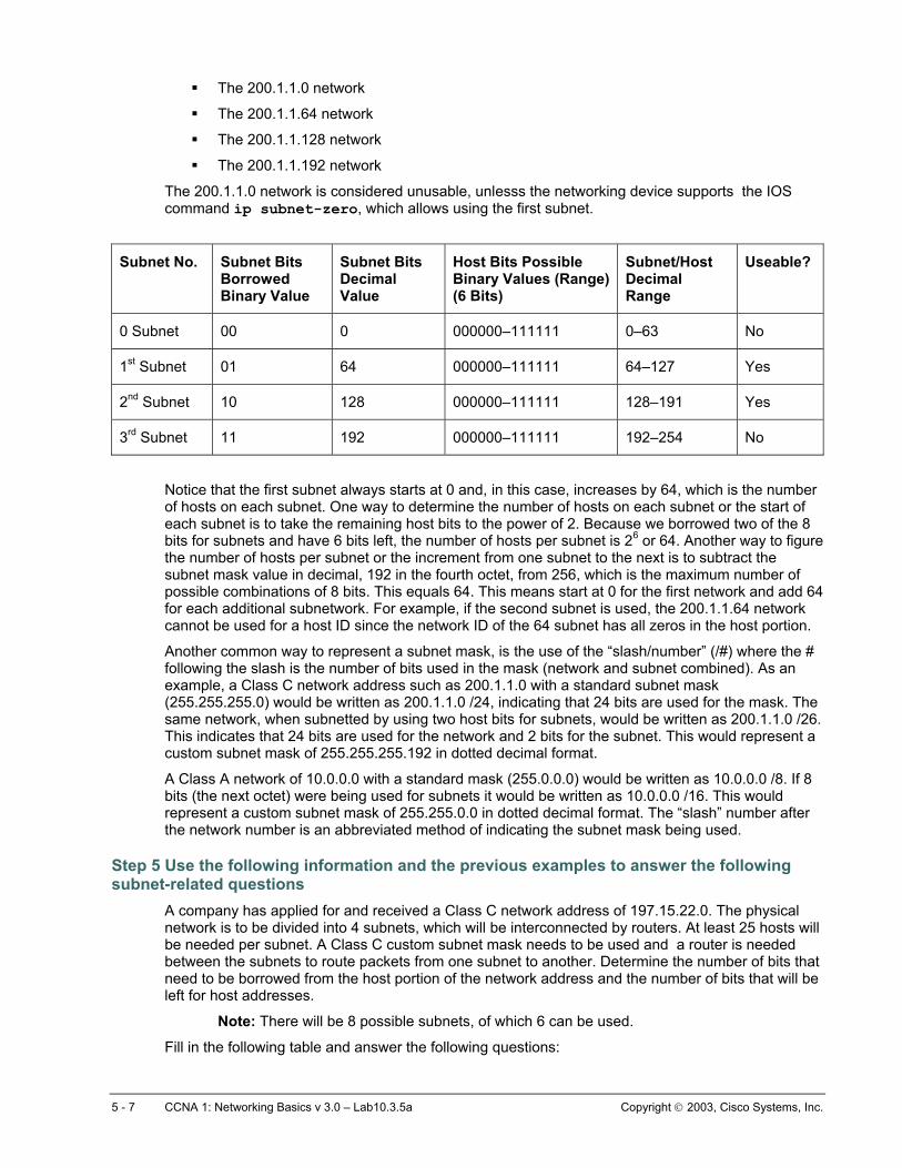
The 200.1.1.0 network
The 200.1.1.64 network
The 200.1.1.128 network
The 200.1.1.192 network
The 200.1.1.0 network is considered unusable, unlesss the networking device supports the IOS command ip subnet-zero, which allows using the first subnet.
Subnet No. Subnet Bits Borrowed Binary Value
Subnet Bits Decimal Value
Host Bits Possible Binary Values (Range) (6 Bits)
Subnet/Host Decimal Range
Useable?
0 Subnet 00 0 000000–111111 0–63 No
1st Subnet 01 64 000000–111111 64–127 Yes
2nd Subnet 10 128 000000–111111 128–191 Yes
3rd Subnet 11 192 000000–111111 192–254 No
Notice that the first subnet always starts at 0 and, in this case, increases by 64, which is the number of hosts on each subnet. One way to determine the number of hosts on each subnet or the start of each subnet is to take the remaining host bits to the power of 2. Because we borrowed two of the 8 bits for subnets and have 6 bits left, the number of hosts per subnet is 26 or 64. Another way to figure the number of hosts per subnet or the increment from one subnet to the next is to subtract the subnet mask value in decimal, 192 in the fourth octet, from 256, which is the maximum number of possible combinations of 8 bits. This equals 64. This means start at 0 for the first network and add 64 for each additional subnetwork. For example, if the second subnet is used, the 200.1.1.64 network cannot be used for a host ID since the network ID of the 64 subnet has all zeros in the host portion.
Another common way to represent a subnet mask, is the use of the “slash/number” (/#) where the # following the slash is the number of bits used in the mask (network and subnet combined). As an example, a Class C network address such as 200.1.1.0 with a standard subnet mask (255.255.255.0) would be written as 200.1.1.0 /24, indicating that 24 bits are used for the mask. The same network, when subnetted by using two host bits for subnets, would be written as 200.1.1.0 /26. This indicates that 24 bits are used for the network and 2 bits for the subnet. This would represent a custom subnet mask of 255.255.255.192 in dotted decimal format.
A Class A network of 10.0.0.0 with a standard mask (255.0.0.0) would be written as 10.0.0.0 /8. If 8 bits (the next octet) were being used for subnets it would be written as 10.0.0.0 /16. This would represent a custom subnet mask of 255.255.0.0 in dotted decimal format. The “slash” number after the network number is an abbreviated method of indicating the subnet mask being used.
Step 5 Use the following information and the previous examples to answer the following subnet-related questions
A company has applied for and received a Class C network address of 197.15.22.0. The physical network is to be divided into 4 subnets, which will be interconnected by routers. At least 25 hosts will be needed per subnet. A Class C custom subnet mask needs to be used and a router is needed between the subnets to route packets from one subnet to another. Determine the number of bits that need to be borrowed from the host portion of the network address and the number of bits that will be left for host addresses.
Note: There will be 8 possible subnets, of which 6 can be used.
Fill in the following table and answer the following questions:
5 - 7 CCNA 1: Networking Basics v 3.0 – Lab10.3.5a Copyright 2003, Cisco Systems, Inc.

Subnet No. Subnet Bits Borrowed Binary Value
Subnet Bits Decimal and Subnet No.
Host Bits Possible Binary Values (Range) (5 Bits)
Subnet/Host Decimal Range
Use?
0 Subnet
1st Subnet
2nd Subnet
3rd Subnet
4th Subnet
5th Subnet
6th Subnet
7th Subnet
NOTES: __________________________________________________________________________
__________________________________________________________________________
__________________________________________________________________________
__________________________________________________________________________
__________________________________________________________________________
__________________________________________________________________________
__________________________________________________________________________
Use the table just developed to help answer the following questions:
1. Which octet(s) represent the network portion of a Class C IP address? _________________
2. Which octet(s) represent the host portion of a Class C IP address? ____________________
3. What is the binary equivalent of the Class C network address in the scenario? 197.15.22.0
Decimal network address: ___________ ___________ ___________ ___________
Binary network address: ___________ ___________ ___________ ___________
4. How many high-order bits were borrowed from the host bits in the fourth octet? ___________
5. What subnet mask must be used? Show the subnet mask in decimal and binary.
Decimal subnet mask: ___________ ___________ ___________ ___________
Binary subnet mask: ___________ ___________ ___________ ___________
6. What is the maximum number of subnets that can be created with this subnet mask? ________
7. What is the maximum number of useable subnets that can be created with this mask? _______
8. How many bits were left in the fourth octet for host IDs? _____________________________
6 - 7 CCNA 1: Networking Basics v 3.0 – Lab10.3.5a Copyright 2003, Cisco Systems, Inc.

9. How many hosts per subnet can be defined with this subnet mask? _____________________
10. What is the maximum number of hosts that can be defined for all subnets with this scenario? Assume the lowest and highest subnet numbers and the lowest and highest host ID on each subnet cannot be used. _____________________________________________________
11. Is 197.15.22.63 a valid host IP address with this scenario? ___________________________
12. Why or why not? __________________________________________________________
13. Is 197.15.22.160 a valid host IP address with this scenario? ___________________________
14. Why or why not? __________________________________________________________
15. Host A has an IP address of 197.15.22.126. Host B has an IP address of 197.15.22.129. Are these hosts on the same subnet? _______ Why?
__________________________________________________________________________
__________________________________________________________________________
__________________________________________________________________________
__________________________________________________________________________
__________________________________________________________________________
7 - 7 CCNA 1: Networking Basics v 3.0 – Lab10.3.5a Copyright 2003, Cisco Systems, Inc.
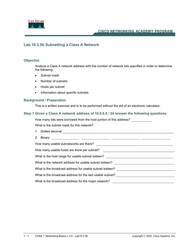
Lab 10.3.5b Subnetting a Class A Network
Objective Analyze a Class A network address with the number of network bits specified in order to determine the following:
• Subnet mask
• Number of subnets
• Hosts per subnet
• Information about specific subnets
Background / Preparation This is a written exercise and is to be performed without the aid of an electronic calculator.
Step 1 Given a Class A network address of 10.0.0.0 / 24 answer the following questions How many bits were borrowed from the host portion of this address? ___________
What is the subnet mask for this network?
1. Dotted decimal ___________________________________________________________
2. Binary _______________ _______________ _______________ _______________
How many usable subnetworks are there? _________________________________________
How many usable hosts are there per subnet? ______________________________________
What is the host range for usable subnet sixteen? ____________________________________
What is the network address for usable subnet sixteen? ________________________________
What is the broadcast address for usable subnet sixteen? _______________________________
What is the broadcast address for the last usable subnet? _______________________________
What is the broadcast address for the major network? _________________________________
1 - 1 CCNA 1: Networking Basics v 3.0 – Lab10.3.5b Copyright 2003, Cisco Systems, Inc.

Lab 10.3.5c Subnetting a Class B Network
Objective The objective of this lab is to provide a subnetting scheme using a Class B network
Background / Preparation This is a written lab and is to be performed without the aid of an electronic calculator.
ABC Manufacturing has acquired a Class B address, 172.16.0.0. The company needs to create a subnetting scheme to provide the following:
• 36 subnets with at least 100 hosts
• 24 subnets with at least 255 hosts
• 10 subnets with at least 50 hosts
It is not necessary to supply an address for the WAN connection since it is supplied by the Internet service provider.
Step 1 Given this Class B network address and these requirements answer the following questions
How many subnets are needed for this network? ______________________________________
What is the minimum number of bits that can be borrowed? ______________________________
What is the subnet mask for this network? __________________________________________
1. Dotted decimal ___________________________________________________________
2. Binary ________________ ________________ ________________ ________________
3. Slash format _____________________________________________________________
How many usable subnetworks are there? __________________________________________
How many usable hosts are there per subnet? _______________________________________
Step 2 Complete the following chart listing the first three subnets and the last 4 subnets
Subnetwork # Subnetwork ID Host Range Broadcast ID
1 - 1 CCNA 1: Networking Basics v 3.0 – Lab10.3.5c Copyright 2003, Cisco Systems, Inc.

What is the host range for subnet two? ____________________________________________
What is the broadcast address for the 126th subnet? ________________________________
What is the broadcast address for the major network? ________________________________
2 - 2 CCNA 1: Networking Basics v 3.0 – Lab10.3.5c Copyright 2003, Cisco Systems, Inc.
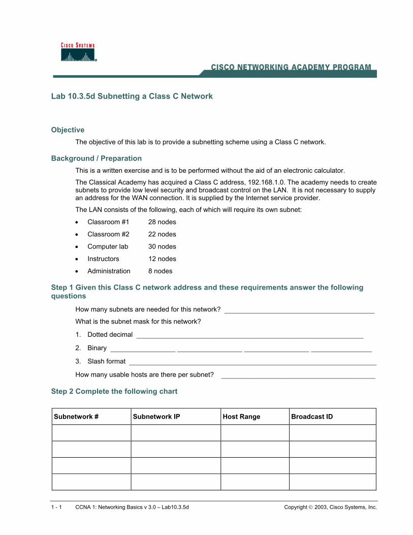
Lab 10.3.5d Subnetting a Class C Network
Objective The objective of this lab is to provide a subnetting scheme using a Class C network.
Background / Preparation This is a written exercise and is to be performed without the aid of an electronic calculator.
The Classical Academy has acquired a Class C address, 192.168.1.0. The academy needs to create subnets to provide low level security and broadcast control on the LAN. It is not necessary to supply an address for the WAN connection. It is supplied by the Internet service provider.
The LAN consists of the following, each of which will require its own subnet:
• Classroom #1 28 nodes
• Classroom #2 22 nodes
• Computer lab 30 nodes
• Instructors 12 nodes
• Administration 8 nodes
Step 1 Given this Class C network address and these requirements answer the following questions
How many subnets are needed for this network? _____________________________________
What is the subnet mask for this network?
1. Dotted decimal ________________________________________________________
2. Binary ________________ ________________ ________________ _______________
3. Slash format _____________________________________________________________
How many usable hosts are there per subnet? ______________________________________
Step 2 Complete the following chart
Subnetwork # Subnetwork IP Host Range Broadcast ID
1 - 1 CCNA 1: Networking Basics v 3.0 – Lab10.3.5d Copyright 2003, Cisco Systems, Inc.

What is the host range for subnet six? ____________________________________________
What is the broadcast address for the 3rd subnet? ____________________________________
What is the broadcast address for the major network? ________________________________
2 - 2 CCNA 1: Networking Basics v 3.0 – Lab10.3.5d Copyright 2003, Cisco Systems, Inc.
1 - 4 CCNA 2: Routers and Routing Basics v 3.0 - Lab 1.2.5 Copyright 2003, Cisco Systems, Inc.
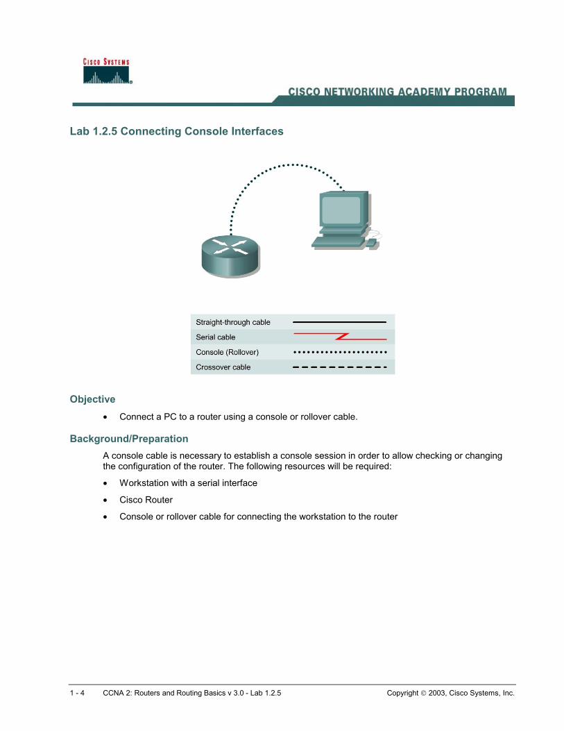
Lab 1.2.5 Connecting Console Interfaces
Objective • Connect a PC to a router using a console or rollover cable.
Background/Preparation A console cable is necessary to establish a console session in order to allow checking or changing the configuration of the router. The following resources will be required:
• Workstation with a serial interface
• Cisco Router
• Console or rollover cable for connecting the workstation to the router

2 - 4 CCNA 2: Routers and Routing Basics v 3.0 - Lab 1.2.5 Copyright 2003, Cisco Systems, Inc.
Step 1 Identify connectors and components a. Examine the router and locate the RJ-45 connector labeled Console.
Step 2 Identify the computer serial interface (COM 1 or 2) a. Examine the computer and locate a 9-pin or 25-pin male connector labeled serial. It may or may
not be identified.
Step 3 Locate the RJ-45 to DB-9 adapter

3 - 4 CCNA 2: Routers and Routing Basics v 3.0 - Lab 1.2.5 Copyright 2003, Cisco Systems, Inc.
Step 4 Locate or build a rollover cable a. Use a rollover cable, making one if necessary of adequate length to connect the router to one of
the workstations.

4 - 4 CCNA 2: Routers and Routing Basics v 3.0 - Lab 1.2.5 Copyright 2003, Cisco Systems, Inc.
Step 5 Connect cabling components a. Connect the rollover cable to the router console port, an RJ-45 connector. Next, connect the
other end of the rollover cable to the RJ-45 to DB-9 adapter. Finally attach the adapter to a PC serial port, either DB-9 or DB-25, depending on the computer.

1 - 2 CCNA 2: Routers and Routing Basics v 3.0 - Lab 1.2.6 Copyright 2003, Cisco Systems, Inc.
Lab 1.2.6 Connecting Router LAN Interfaces
Objective • Identify the Ethernet or Fast Ethernet interfaces on the router.
• Identify and locate the proper cables to connect the router and PC to a hub or switch.
• Use the cables to connect the router and PC to the hub or switch.
Background/Preparation This lab focuses on the ability to connect the physical cabling between Ethernet LAN devices such as hubs and switches and the appropriate Ethernet interface on a router. The computer(s) and router should be preconfigured with the correct IP network settings. Start this lab with the computer(s), router and hub or switch all turned off and unplugged. The following resources will be required:
• At least one workstation with an Ethernet 10/100 NIC installed
• One Ethernet switch or hub
• One router with an RJ-45 Ethernet or Fast Ethernet interface, or an AUI interface
• 10BASE-T AUI, DB-15 to RJ-45 transceiver, for a 2500 Series router with an AUI Ethernet interface

2 - 2 CCNA 2: Routers and Routing Basics v 3.0 - Lab 1.2.6 Copyright 2003, Cisco Systems, Inc.
• Several Ethernet cables, straight-through and crossover, to choose from for connecting the workstation and router to the hub or switch
Step 1 Identify the Ethernet or FastEthernet interfaces on the router a. Examine the router.
b. What is the model number of the router? __________________
c. Locate one or more RJ-45 connectors on the router labeled 10/100 Ethernet. This identifier may vary depending on the type of router used. A 2500 series router will have an AUI DB-15 Ethernet port labeled AUI 0. These will require a 10BASE-T transceiver to connect to the RJ-45 cable.
d. Identify the Ethernet ports shown that could be used for connecting the routers. Record the
information below. Record the AUI port numbers if the router is a Cisco 2500 series router.
Router Port Port
Step 2 Identify the proper cables and connect router a. The connection between the router and the hub will be accomplished using a cat 5 straight
through patch cable. Locate a patch cable that is long enough to reach from the router to the hub. Be sure to examine the cable ends carefully and select only straight through cables.
b. Use a cable to connect the Ethernet interface that uses the 0 (zero) designation on the router to a port on the hub or switch. Also use the 10BASE-T AUI transceiver for the 2500 series.
Step 3 Locate the RJ-45 to DB-9 adapter a. The computer(s) will also connect to the hub using a straight through patch cable. Run Category
5 patch cables from each PC to where the switch or hub is located. Connect one end of these cables to the RJ-45 connector on the computer NIC and connect the other end to a port on the hub or switch. Be sure to examine the cable ends carefully and select only straight through cables.
Step 4 Locate or build a rollover cable a. Plug in and turn on the routers, computers, and hub or switch.
b. To verify the router connections, insure that the link light on the router interface and the hub/switch interface are both lit.
c. To verify the computer connections, insure that the link light on the NIC and the hub interface are both lit.

1 - 3 CCNA 2: Routers and Routing Basics v 3.0 - Lab 1.2.7 Copyright 2003, Cisco Systems, Inc.
Lab 1.2.7 Connecting WAN Interfaces
Objective
• Identify the serial interfaces on the router.
• Identify and locate the proper cables to interconnect the routers.
• Use the cables to connect the router.
Background/Preparation This lab connects two routers together using directly attached cables to simulate a WAN link. This allows the routers to be configured and tested as though they were geographically separated. This simulated WAN link takes the place of the service providers network and can be thought of as a CSU/DSU eliminator. The first steps involve finding out what kind of connections are on the router and what kind of cables are needed.
Step 1 Identify the serial interfaces on the router a. Examine the router.
b. What is the model number of the router? __________________
c. What is the model number of the second router? __________________

2 - 3 CCNA 2: Routers and Routing Basics v 3.0 - Lab 1.2.7 Copyright 2003, Cisco Systems, Inc.
d. How many serial ports are there on each router that could be used for connecting the routers? Record the information below.
Router Name Serial Port Serial Port Serial Port Router 1 Router 2
Step 2 Identify and locate the proper cables a. Inspect the serial cables available in the lab. Depending on what type of router and/or serial card
used, the router may have different connectors. The two most common types are the DB-60 and the smart serial connectors. Using the table below indicate which type of interfaces the routers have.
Router Smart Serial
DB-60
1
2
b. Since this lab will not be connected to a live leased line, one of the routers will need to provide
the clocking for the circuit. This is normally provided to each of the routers by the service provider. To provide this clocking signal in the lab, one of the routers will need a DCE cable instead of the DTE cable used on the other router.
In this lab, the connection between routers uses one DCE cable and one DTE cable. The DCE-DTE connection between routers is referred to as a null serial cable. This lab will use one V.35 DCE cable and one V.35 DTE cable to simulate the WAN connection.
The V.35 DCE connector is usually a female V.35 (34-pin) connector. The DTE cable has a male V.35 connector. The cables are also labeled as DCE or DTE on the router end of the cable. Using the chart below, identify the V.35 cable that will be used, on each router, by placing a check mark in the appropriate box.
Router
DTE DCE
Router 1
Router 2

3 - 3 CCNA 2: Routers and Routing Basics v 3.0 - Lab 1.2.7 Copyright 2003, Cisco Systems, Inc.
c. After having indicated the cables required to interconnect the router locate them in the equipment inventory.
Step 3 Cable the routers a. The DTE and DCE V.35 cables must now be joined together. Holding one of the V.35 ends in
each hand examine the pins and sockets as well as the threaded connectors. Note that there is only one proper way for the cables to fit together. Align the pins on the male cable with the sockets on the female cable and gently couple them. Very little effort should be required to accomplish this. When they are joined, turn the thumbscrews clockwise and secure the connectors.
b. Before making the connection to one of the routers, examine the connector on the router and the cable. Note that the connectors are tapered to help prevent improper connection. Holding the connector in one hand, orient the cable and router connecters so that the tapers match. Now push the cable connector partially into the router connector. It probably will not go on all the way as the threaded connectors need to be tightened in order for the cable to be inserted completely. While holding the cable in one hand and gently pushing the cable toward the router, turn one of the thumb screws clockwise, 3 or 4 rounds to start the screws. Now turn the other thumbscrew clockwise, 3 or 4 rounds to get it started. At this point the cable should be attached enough enabling the use of both hands to advance each thumbscrew at the same rate until the cable is fully inserted. Do not over-tighten these connectors.

1 - 4 CCNA 2: Routers and Routing Basics v 3.0 - Lab 2.2.4 Copyright 2003, Cisco Systems, Inc.
Lab 2.2.4 Establishing a Console Session with HyperTerminal
Objective • Connect a router and workstation using a console cable.
• Configure HyperTerminal to establish a console session with the router.
Background/Preparation HyperTerminal is a simple Windows-based terminal emulation program that can be used to connect to the console port on the router. A PC with HyperTerminal provides a keyboard and monitor for the router. Connecting to the console port with a rollover cable and using HyperTerminal is the most basic way to access a router for checking or changing its configuration.
Set up a network similar to the one in the diagram. Any router that meets the interface requirements may be used. Possible routers include 800, 1600, 1700, 2500, 2600 routers, or a combination. The following resources will be required:
• Workstation with a serial interface and HyperTerminal
• Cisco Router
• Console (rollover) cable for connecting the workstation to the router
Step 1 Basic Router Configuration a. Connect a rollover cable to the console port on the router and the other end to the PC with a DB-
9 or DB-25 adapter to a COM port. This should be completed prior to powering on any devices.
2 - 4 CCNA 2: Routers and Routing Basics v 3.0 - Lab 2.2.4 Copyright 2003, Cisco Systems, Inc.
Step 2 Start HyperTerminal program a. Turn on the computer and router.
b. From the Widows taskbar, locate the HyperTerminal program:
Start > Programs > Accessories > Communications > Hyper Terminal
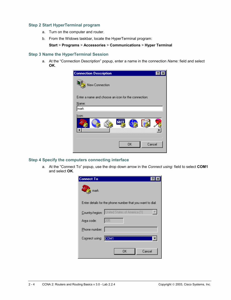
Step 3 Name the HyperTerminal Session a. At the “Connection Description” popup, enter a name in the connection Name: field and select
OK.
Step 4 Specify the computers connecting interface a. At the “Connect To” popup, use the drop down arrow in the Connect using: field to select COM1
and select OK.

3 - 4 CCNA 2: Routers and Routing Basics v 3.0 - Lab 2.2.4 Copyright 2003, Cisco Systems, Inc.
Step 5 Specify the interface connection properties a. At the “COM1 Properties” popup, use the drop down arrows to select:
Bits per second: 9600 Data bits: 8 Parity: None Stop bits: 1 Flow control: None
Then select OK.
b. When the HyperTerminal session window comes up, turn on the router. If the router is already
on, press the Enter key. There should be a response from the router.
If there is, then the connection has been successfully completed.
c. Record in the engineering journal the correct procedure for establishing a console session with the router.
Step 6 Closing the session a. To end the console session from a HyperTerminal session, select:
File > Exit b. When the HyperTerminal disconnect warning popup appears, select Yes.

4 - 4 CCNA 2: Routers and Routing Basics v 3.0 - Lab 2.2.4 Copyright 2003, Cisco Systems, Inc.
c. The computer will then ask if the session is to be saved. Select Yes.
Step 7 Reopen the HyperTerminal connection, as shown in Step 2 a. At the “Connection Description” popup, select Cancel.
b. To open the saved console session from HyperTerminal, select:
File > Open
The saved session will now appear and by double-clicking on the name, the connection will open without reconfiguring it each time.
Step 8 Terminating the HyperTerminal session a. Close HyperTerminal.
b. Shut down the router.
Upon completion of the previous steps, logoff by typing exit. Turn the router off.

1 - 3 CCNA 2: Routers and Routing Basics v 3.0 - Lab 2.2.9 Copyright 2003, Cisco Systems, Inc.
Lab 2.2.9 Command Line Fundamentals
Objective
• Log into a router and go to the user and privileged modes.
• Use several basic router commands to determine how the router is configured.
• Use the router HELP facility.
• Use command history and editing features.
• Logout of the router.
Background/Preparation HyperTerminal is a simple Windows-based terminal emulation program that can be used to connect to the routers console port. A PC with HyperTerminal provides a keyboard and monitor for the router. Connecting to the console port with a rollover cable and using HyperTerminal is the most basic way to access a router for checking or changing its configuration.
Set up a network similar to the one in the diagram. Any router that meets the interface requirements may be used. Possible routers include 800, 1600, 1700, 2500, 2600 routers, or a combination. The configuration output used in this lab is produced from a 1721 series router. Other routers may produce slightly different output.
The following resources will be required:
• Workstation with a serial interface and HyperTerminal
• Cisco Router
• Rollover, or console, cable for connecting the workstation to the router

2 - 3 CCNA 2: Routers and Routing Basics v 3.0 - Lab 2.2.9 Copyright 2003, Cisco Systems, Inc.
The following steps are intended to be executed on each router unless specifically instructed otherwise.
Step 1 Start HyperTerminal a. Start a HyperTerminal session as performed in the Establishing a HyperTerminal session lab.
Step 2 Log into the router a. Log into the router. Enter the password cisco if prompted.
b. If the prompt shows “Router” this is the default. Something other than that may appear if this router has been named. What prompt did the router display? __________________________
c. What does the prompt symbol following a router name mean? _________________________
Step 3 Use the HELP feature a. Enter the help command by typing the ? at the user EXEC router promp.
Router>?
b. List eight available commands from the router response.
Step 4 Enter privileged EXEC mode a. Enter enable mode by using the enable command. If a password is asked for, enter class
when prompted.
Router>enable [Enter]
b. Was enable one of the commands available from Step 2? _________________________________
c. What changed in the router prompt display and what does it mean?
_______________________________________________________________________
Step 5 Use the help feature a. Enter the help mode by typing a question mark (?) at the router privileged EXEC prompt.
Router#?
b. List ten (10) available commands from the router response.

3 - 3 CCNA 2: Routers and Routing Basics v 3.0 - Lab 2.2.9 Copyright 2003, Cisco Systems, Inc.
Step 6 List the show commands a. List all show commands by entering show ? at the router privileged EXEC prompt.
Router#show ?
b. Is running-config one of the available commands from this mode?
__________________________________________________________________________
Step 7 Examine the running configuration a. Display the running router configuration by using the command show running-config at the
privileged EXEC router prompt. Router#show running-config
b. List six key pieces of information shown with this command:
Step 8 Examine the configuration in more detail a. Continue looking at the configuration.
b. When the word "more" appears, press the space bar. By pressing the space bar the router will display the next page of information.
c. What happened when the space bar was pressed ?
__________________________________________________________________________
Step 9 Use the command history feature a. Use the command history to see and reuse the previously entered commands. Press the up
arrow or Ctrl-p to see the last entered command. Press it again to go to the command before that. Press the down arrow or Ctrl-n to go back through the list. This function lets the command history be viewed.
b. What appeared at the router prompt when the up arrow was pressed?
__________________________________________________________________________
Step 10 Logoff and turn the router off

1 - 5 CCNA 2: Routers and Routing Basics v 3.0 - Lab 3.1.2 Copyright 2003, Cisco Systems, Inc.
Lab 3.1.2 Command Modes and Router Identification
Objective
• Identify basic router modes of user EXEC and privileged EXEC.
• Use commands to enter specific modes.
• Become familiar with the router prompt for each mode.
• Assign a name to the router.
Background/Preparation Any router that meets the interface requirements may be used. Possible routers include 800, 1600, 1700, 2500, 2600 routers, or a combination. Refer to the chart at the end of the lab to correctly identify the interface identifiers to be used based on the equipment in the lab. The configuration output used in this lab is produced from 1721 series routers. Any other router used may produce slightly different output. The following steps are intended to be executed on each router unless specifically instructed otherwise.
Start a HyperTerminal session as performed in the Establishing a HyperTerminal session lab.
Note: Go to the erase and reload instructions at the end of this lab. Perform those steps before continuing with this lab.
Step 1 Login to the router in user EXEC mode a. Connect to the router and login.
b. What prompt did the router display?
__________________________________________________________________________

2 - 5 CCNA 2: Routers and Routing Basics v 3.0 - Lab 3.1.2 Copyright 2003, Cisco Systems, Inc.
c. What does this prompt mean?
__________________________________________________________________________
Step 2 Login to the router in privileged EXEC mode a. Enter enable at the user mode prompt.
Router>enable
b. If prompted for a password, enter the password class.
c. What prompt did the router display?
__________________________________________________________________________ d. What does this prompt mean?
__________________________________________________________________________
Step 3 Enter global configuration mode a. Enter configure terminal at the privilege mode prompt.
Router#configure terminal
b. What prompt did the router display? ____________________________________________
c. What does this prompt mean?
__________________________________________________________________________
Step 4 Enter router configuration mode a. Enter router rip at the global configuration mode.
Router(config)#router rip
b. What prompt did the router display? _________________________________________
c. What does this prompt mean?
__________________________________________________________________________
Step 5 Exit from router mode and go into interface configuration mode a. Enter exit at the prompt to return to global configuration mode.
Router(config-router)#exit
b. Enter interface serial 0 at the global configuration mode prompt.
Note: See chart for the interface identifier. Router(config)#interface serial 0
c. What prompt did the router display? _____________________
d. What does this prompt mean?
__________________________________________________________________________
e. Enter exit at the prompt to return to global configuration mode.
Router(config-if)#exit

3 - 5 CCNA 2: Routers and Routing Basics v 3.0 - Lab 3.1.2 Copyright 2003, Cisco Systems, Inc.
Step 6 Assign a name to the router a. Router(config)#hostname GAD
b. What prompt did the router display? _____________________
c. What does this prompt mean?
__________________________________________________________________________ d. What change has occurred in the prompt?
__________________________________________________________________________
Step 7 Exit the router a. Enter exit at the prompt to close out of the router.
GAD(config)#exit
Upon completion of the previous steps, logoff by typing exit. Turn the router off.

1 - 6 CCNA 2: Routers and Routing Basics v 3.0 - Lab 3.1.3 Copyright 2003, Cisco Systems, Inc.
Lab 3.1.3 Configuring Router Passwords
Objective
• Configure a password for console login to user EXEC mode.
• Configure a password for virtual terminal (Telnet) sessions.
• Configure a secret password for privileged EXEC mode.
Background/Preparation Any router that meets the interface requirements may be used. Possible routers include 800, 1600, 1700, 2500, 2600 routers, or a combination. Refer to the chart at the end of the lab to correctly identify the interface identifiers to be used based on the equipment in the lab. The configuration output used in this lab is produced from 1721 series routers. Any other router used may produce slightly different output. The following steps are intended to be executed on each router unless specifically instructed otherwise.
Start a HyperTerminal session as performed in the Establishing a HyperTerminal session lab.
Note: Go to the erase and reload instructions at the end of this lab. Perform those steps on all routers in this lab assignment before continuing.
Step 1 Login to the router in user EXEC mode a. Connect to the router and login.
b. What prompt did the router display?
__________________________________________________________________________

2 - 6 CCNA 2: Routers and Routing Basics v 3.0 - Lab 3.1.3 Copyright 2003, Cisco Systems, Inc.
c. What does this prompt mean?
__________________________________________________________________________
Step 2 Login to the router in privileged EXEC mode a. Enter enable at the user EXEC mode prompt.
Router>enable
b. What prompt did the router display?
__________________________________________________________________________ c. What does this prompt mean?
__________________________________________________________________________
Step 3 Enter global configuration mode a. Enter configure terminal at the privilege EXEC mode prompt.
Router#configure terminal
b. What prompt did the router display? ____________________________________________
c. What does this prompt mean?
__________________________________________________________________________
Step 4 Enter a hostname of GAD for this router a. Enter hostname GAD at the prompt.
Router(config)#hostname GAD
b. What prompt did the router display?
__________________________________________________________________________
c. What does this prompt mean?
__________________________________________________________________________
Step 5 Configure and exit Configure the console password on the router and exit from line console: GAD(config)#line console 0 GAD(config-line)#password cisco GAD(config-line)#login GAD(config-line)#exit GAD(config)#
Step 6 Configure and exit Configure the password on the virtual terminal lines and exit line mode:
GAD(config)#line vty 0 4 GAD(config-line)#password cisco GAD(config-line)#login GAD(config-line)#exit GAD(config)#
3 - 6 CCNA 2: Routers and Routing Basics v 3.0 - Lab 3.1.3 Copyright 2003, Cisco Systems, Inc.
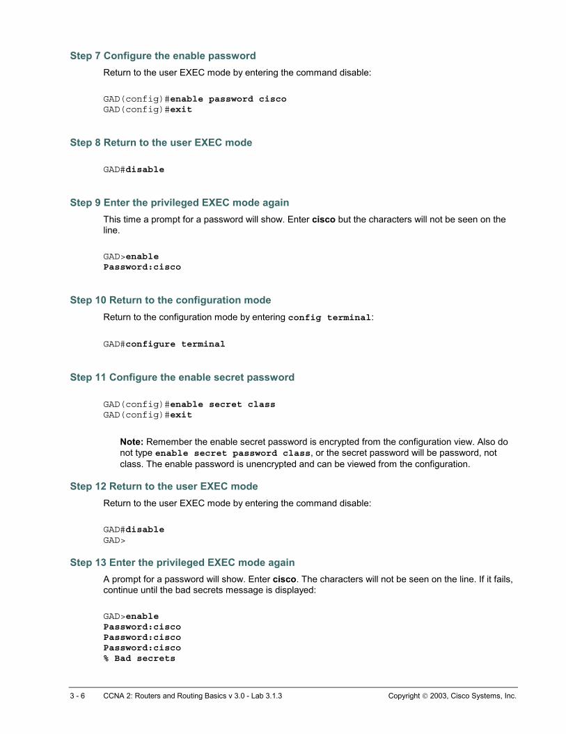
Step 7 Configure the enable password Return to the user EXEC mode by entering the command disable: GAD(config)#enable password cisco GAD(config)#exit
Step 8 Return to the user EXEC mode
GAD#disable
Step 9 Enter the privileged EXEC mode again This time a prompt for a password will show. Enter cisco but the characters will not be seen on the line.
GAD>enable Password:cisco
Step 10 Return to the configuration mode Return to the configuration mode by entering config terminal:
GAD#configure terminal
Step 11 Configure the enable secret password GAD(config)#enable secret class GAD(config)#exit
Note: Remember the enable secret password is encrypted from the configuration view. Also do not type enable secret password class, or the secret password will be password, not class. The enable password is unencrypted and can be viewed from the configuration.
Step 12 Return to the user EXEC mode Return to the user EXEC mode by entering the command disable: GAD#disable GAD>
Step 13 Enter the privileged EXEC mode again A prompt for a password will show. Enter cisco. The characters will not be seen on the line. If it fails, continue until the bad secrets message is displayed:
GAD>enable Password:cisco Password:cisco Password:cisco % Bad secrets

4 - 6 CCNA 2: Routers and Routing Basics v 3.0 - Lab 3.1.3 Copyright 2003, Cisco Systems, Inc.
Step 14 Enter the privileged EXEC mode again A prompt for a password will show. Enter class. The characters will not be displayed on the line:
GAD>enable Password:class GAD#
Note: The enable secret password takes precedence over the enable password. So once an enable secret password is entered the enable password no longer is accepted.
Step 15 Show the routers running configuration a. Is there an encrypted password? ______________________________________________
b. Are there any other passwords? _______________________________________________
c. Are any of the other passwords encrypted? _______________________________________
Upon completion of the previous steps, logoff by typing exit. Turn the router off.

1 - 4 CCNA 2: Routers and Routing Basics v 3.0 - Lab 3.1.4 Copyright 2003, Cisco Systems, Inc.
Lab 3.1.4 Using Router show Commands
Objective
• Become familiar with the basic router show commands.
• Retrieve the current running configuration from RAM using show running-config.
• View the backup configuration file in NVRAM using show startup-config.
• View the IOS file information using show flash and show version.
• View the current status of the router interfaces using show interface.
• View the status of any configured Layer 3 protocol using show protocol.
Background/Preparation This lab helps the student become familiar with the router show commands. The show commands are the most important information-gathering commands available for the router.
• show running-config (or show run) is probably the single most valuable command to help determine the current status of a router, because it displays the active configuration file running in RAM.
• show startup-config (or show start) displays the backup configuration file that is stored in non-volatile RAM (NVRAM). This is the file that will be used to configure the router when it is first started or rebooted with the reload command. All the detailed router interface settings are contained in this file.
• show flash is used to view the available flash memory and the amount used. Flash is where the Cisco Internetwork Operating System (IOS) file or image is stored.
2 - 4 CCNA 2: Routers and Routing Basics v 3.0 - Lab 3.1.4 Copyright 2003, Cisco Systems, Inc.
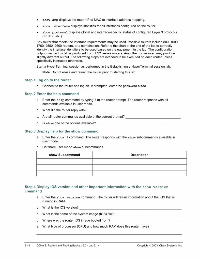
• show arp displays the router IP to MAC to interface address mapping.
• show interface displays statistics for all interfaces configured on the router.
• show protocol displays global and interface-specific status of configured Layer 3 protocols (IP, IPX, etc.).
Any router that meets the interface requirements may be used. Possible routers include 800, 1600, 1700, 2500, 2600 routers, or a combination. Refer to the chart at the end of the lab to correctly identify the interface identifiers to be used based on the equipment in the lab. The configuration output used in this lab is produced from 1721 series routers. Any other router used may produce slightly different output. The following steps are intended to be executed on each router unless specifically instructed otherwise.
Start a HyperTerminal session as performed in the Establishing a HyperTerminal session lab.
Note: Do not erase and reload the router prior to starting this lab.
Step 1 Log on to the router a. Connect to the router and log on. If prompted, enter the password cisco.
Step 2 Enter the help command a. Enter the help command by typing ? at the router prompt. The router responds with all
commands available in user mode.
b. What did the router reply with? ________________________________________________
c. Are all router commands available at the current prompt? ____________________________
d. Is show one of the options available? ___________________________________________
Step 3 Display help for the show command a. Enter the show ? command. The router responds with the show subcommands available in
user mode.
b. List three user mode show subcommands.
show Subcommand Description
Step 4 Display IOS version and other important information with the show version command
a. Enter the show version command. The router will return information about the IOS that is running in RAM.
b. What is the IOS version? ____________________________________________________
c. What is the name of the system image (IOS) file? __________________________________
d. Where was the router IOS image booted from? ____________________________________
e. What type of processor (CPU) and how much RAM does this router have?
__________________________________________________________________________

3 - 4 CCNA 2: Routers and Routing Basics v 3.0 - Lab 3.1.4 Copyright 2003, Cisco Systems, Inc.
f. How many Ethernet interfaces does this router have? _________How many serial interfaces? _________
g. The router backup configuration file is stored in non-volatile random access memory (NVRAM). How much NVRAM does this router have? ______________________________________
h. The router operating system (IOS) is stored in Flash memory. How much Flash memory does this router have? __________________________________________________________
i. What is the configuration register set to? _________________________________________
Step 5 Display the time and date for the router
a. Enter the show clock command. What information is displayed? ______________________
Step 6 Display a cached list of host names and addresses a. Enter the show hosts command. What information is displayed with show hosts?
__________________________________________________________________________
Step 7 Display users who are connected to the router a. Enter the show users command. What information is displayed with show users?
__________________________________________________________________________
Step 8 Show the command buffer a. Enter the show history command. What information is displayed with show history?
_______________________________________________________________________
Step 9 Enter privileged EXEC mode a. From user EXEC mode, enter privileged EXEC mode using the enable command.
b. Enter the enable password class.
c. What command did you use to enter privileged EXEC mode? __________________________
d. How do you know if you are in privileged EXEC mode? ______________________________
Step 10 Enter the help command a. Enter the show ? command at the router prompt. What did the router reply with?
_______________________________________________________________________
b. How is this output different from the one you got in user EXEC mode in Step 3?
_______________________________________________________________________
Step 11 Show the router ARP table a. Enter the show arp command at the router prompt. What is the ARP table?
_______________________________________________________________________
Step 12 Show information about the Flash memory device a. Enter show flash at the router prompt.
b. How much Flash memory is available and used? ___________________________________

4 - 4 CCNA 2: Routers and Routing Basics v 3.0 - Lab 3.1.4 Copyright 2003, Cisco Systems, Inc.
c. What is the file that is stored in Flash memory? ____________________________________
d. What is the size in bytes of the Flash memory? ____________________________________
Step 13 Show information about the active configuration file a. Enter show running-config (or show run) at the router prompt. What important information
is displayed with show run?
__________________________________________________________________________
__________________________________________________________________________
__________________________________________________________________________
__________________________________________________________________________
Step 14 Show information about the backup configuration file a. Enter show startup-config (or show start) at the router prompt. What important
information is displayed with show start, and where is this information kept?
_______________________________________________________________________
Step 15 Display statistics for all interfaces configured on the router a. Enter show interface at the router prompt.
b. Find the following information for interface Ethernet 0 or Fast Ethernet 0/0:
1. What is MTU? ______________________________________________________
2. What is rely? _______________________________________________________
3. What is load? ______________________________________________________
c. Find the following information for interface Serial 0
1. What is the IP address and subnet mask? __________________________________
2. What data link layer encapsulation is being used? ____________________________
Step 16 Display the protocols configured on the router a. Enter show protocol at the router prompt. What important information is displayed?
__________________________________________________________________________
Upon completion of the previous steps, logoff by typing exit. Turn the router off.

1 - 5 CCNA 2: Routers and Routing Basics v 3.0 - Lab 3.1.5 Copyright 2003, Cisco Systems, Inc.
Lab 3.1.5 Configuring a Serial Interface
Objective • Configure a serial interface on each of two routers so they can communicate.
Background/Preparation Any router that meets the interface requirements may be used. Possible routers include 800, 1600, 1700, 2500, 2600 routers, or a combination. Refer to the chart at the end of the lab to correctly identify the interface identifiers to be used based on the equipment in the lab. The configuration output used in this lab is produced from 1721 series routers. Any other router used may produce slightly different output. The following steps are intended to be executed on each router unless specifically instructed otherwise.
Start a HyperTerminal session as performed in the Establishing a HyperTerminal session lab.
Note: Go to the erase and reload instructions at the end of this lab. Perform those steps on all routers in this lab assignment before continuing.
Step 1 Basic Router Configuration a. Configure the router. Connect the routers as shown in the diagram. This lab requires a null serial
cable and two rollover or console cables.

2 - 5 CCNA 2: Routers and Routing Basics v 3.0 - Lab 3.1.5 Copyright 2003, Cisco Systems, Inc.
Step 2 Configure the name and passwords for Router 1 a. On Router 1, enter the global configuration mode and configure the hostname as shown in the
chart.
b. Configure the console, virtual terminal and enable passwords. If there are any problems, refer to the Lab 3.1.3 Configuring Router Passwords.
Step 3 Configure serial interface Serial 0 From global configuration mode, configure serial interface Serial 0 on Router GAD. Refer to Interface Summary.
GAD(config)#interface serial 0 GAD(config-if)#ip address 192.168.15.1 255.255.255.0 GAD(config-if)#clock rate 56000 GAD(config-if)#no shutdown GAD(config-if)#exit GAD(config)#exit
Note: Once the interface configuration mode is entered, note the IP address of the interface. Enter the subnet mask. Enter the clock rate only on the DCE side of the device. The command no shutdown turns on the interface. Shutdown is when the interface is off.
Step 4 Save the running configuration Save the running configuration to the startup configuration at the privileged EXEC mode:
GAD#copy running-config startup-config
Note: Save the running configuration for the next time that the router is restarted. The router can be restarted either by a software reload command or a power shutdown. The running configuration will be lost if the running configuration is not saved. The router uses the startup configuration when the router is started.
Step 5 Display information about Serial interface 0 on GAD a. Enter the command show interface serial 0 on GAD. Refer to interface chart.
GAD#show interface serial 0
This will show the details of interface serial 0.
b. List at least three details discovered by issuing this command.
c. Serial0/0 is ___________________. Line protocol is___________________ .
d. Internet address is _____________________.
e. Encapsulation _________________________
f. To what OSI layer is the “Encapsulation” referring? _______________________________
g. If the Serial interface was configured, why did the show interface serial 0 say that the interface is down?
__________________________________________________________________________

3 - 5 CCNA 2: Routers and Routing Basics v 3.0 - Lab 3.1.5 Copyright 2003, Cisco Systems, Inc.
Step 6 Configure the name and passwords for Router 2 a. On the Birmingham router, enter the global configuration mode. Configure hostname, console,
virtual terminal and enable passwords as shown in the previous chart.
Step 7 Configure serial interface Serial 0 From the configure terminal mode, configure serial interface Serial 0 on Router BHM. Refer to interface chart.
BHM(config)#interface serial 0 BHM(config-if)#ip address 192.168.15.1 255.255.255.0 BHM(config-if)#no shutdown BHM(config-if)#exit BHM(config)#exit
Step 8 Save the running configuration Save the running configuration to the startup configuration at the privileged EXEC mode:
BHM#copy running-config startup-config
Step 9 Display information about Serial interface 0 on BHM a. Enter the command show interface serial 0 on BHM. Refer to interface chart.
BHM#show interface serial 0
This will show the details of interface serial 0.
b. List at least three details discovered by issuing this command.
c. Serial0/0 is ___________________, line protocol is ___________________ .
d. Internet address is ___________________ .
e. Encapsulation ___________________
f. What is the difference in the Line and Protocol status recorded on GAD earlier? Why?
__________________________________________________________________________
Step 10 Verify that the serial connection is functioning a. ping the serial interface of the other router.
BHM#ping 192.168.15.1 GAD#ping 192.168.15.2
b. From GAD, ping the BHM router serial interface. Does the ping work? _________________
c. From BHM, ping the GAD router serial interface. Does the ping work? _________________
d. If the answer is no for either question, troubleshoot the router configurations to find the error. Then ping the interfaces again until the answer to both questions is yes.
Upon completion of the previous steps, logoff by typing exit. Turn the router off. Remove and store the cables and adapter.

1 - 5 CCNA 2: Routers and Routing Basics v 3.0 - Lab 3.1.6 Copyright 2003, Cisco Systems, Inc.
Lab 3.1.6 Making Configuration Changes
Objective • Configure some basic router settings.
• Bring interfaces up and down.
• Make changes to the router configuration.
Background/Preparation Any router that meets the interface requirements may be used. Possible routers include 800, 1600, 1700, 2500, 2600 routers, or a combination. Refer to the chart at the end of the lab to correctly identify the interface identifiers to be used based on the equipment in the lab. The configuration output used in this lab is produced from 1721 series routers. Any other router used may produce slightly different output. The following steps are intended to be executed on each router unless specifically instructed otherwise.
Start a HyperTerminal session as performed in the Establishing a HyperTerminal session lab.
Note: Go to the erase and reload instructions at the end of this lab. Perform those steps on all routers in this lab assignment before continuing.

2 - 5 CCNA 2: Routers and Routing Basics v 3.0 - Lab 3.1.6 Copyright 2003, Cisco Systems, Inc.
Step 1 Basic Router Configuration a. Connect the routers as shown in the diagram. This lab requires a console (rollover) and a patch
(straight-through) cable.
Step 2 Configure hostname and passwords a. On the Gadsden router, enter the global configuration mode. Configure the hostname as shown
in the chart. Configure the console, virtual terminal and enable passwords.
Step 3 Configure interface Serial 0 a. From the configure terminal mode, configure serial interface 0 on Router GAD. Refer to interface
chart. GAD(config)#interface Serial 0 GAD(config-if)#ip address 192.168.14.1 255.255.255.0 GAD(config-if)#no shutdown GAD(config-if)#description Connection to the host GAD(config-if)#exit GAD(config)#exit
Note: Once interface configuration mode is entered, note the IP address of the interface. Enter the subnet mask. Enter the clock rate only on the DCE side of the device. The command no shutdown turns on the interface. Shutdown is when the interface is off.
Step 4 Save the configuration a. Save the running configuration to the startup configuration at the privileged EXEC mode.
GAD#copy running-config startup-config
Note: Save the running configuration for the next time that the router is restarted. The router can be restarted either by a software reload command or a power shutdown. The running configuration will be lost if the running configuration is not saved. The router uses the startup configuration when the router is started.
Step 5 Verify the configuration a. Issue the show running-config command from the privileged EXEC mode
b. If the configuration is not correct, reenter any incorrect commands.
Step 6 Modify the configuration a. Based on the new table, reconfigure the GAD router. Change the router hostname. Change the
enable/VTY/console passwords. Remove the secret password and interface description.
Note: Before making changes to the interface IP address and subnet mask bring the interface down as shown in Step 7.
Router Name
Serial 0 Address
Subnet mask
Enable Secret
passwordEnable/VTY/Console
passwords
Gadsden
172.16.0.1 255.255.0.0 Cisco1
3 - 5 CCNA 2: Routers and Routing Basics v 3.0 - Lab 3.1.6 Copyright 2003, Cisco Systems, Inc.
b. To change information, go to the proper command mode and retype the command with the new information. To remove an old command, go to the proper command mode and retype the command exactly as it was entered with the word no in front of it. For example: Gadsden(config-if)#description Connection to the host Gadsden(config-if)#no description Connection to the host
Step 7 Bring down Serial interface 0 a. Bring the interface down for maintenance by entering:
GAD(config)#interface Serial 0 GAD(config-if)#shutdown GAD(config-if)#exit GAD(config)#exit GAD#
b. Issue the show interface Serial 0 and note the interface status.
c. Issue the show running-config command and note the status of interface Serial 0:
__________________________________________________________________________
d. Make changes to the interface.
Step 8 Bring up Serial interface 0 a. To make the interface operational, enable the interface by entering:
GAD(config)#interface Serial 0 GAD(config-if)#no shutdown GAD(config-if)#exit GAD (config)#exit
b. Issue the show interface Serial 0 and note the interface status.
c. Serial 0 is ________________. Line protocol is ________________.
Step 9 Verify the configuration a. Issue a show running-config command from the privileged EXEC mode to see if the
modifications were properly made. If the configuration is not correct, reenter any incorrect commands and verify again.
Upon completion of the previous steps, logoff by typing exit. Turn the router off.

1 - 4 CCNA 2: Routers and Routing Basics v 3.0 - Lab 3.1.7 Copyright 2003, Cisco Systems, Inc.
Lab 3.1.7 Configuring an Ethernet Interface
Objective • Configure an Ethernet interface on the router with an IP address and a subnet mask.
Background/Preparation In this lab the Cisco Discovery Protocol (CDP) commands will be used. CDP discovers and shows information about directly connected Cisco devices (routers and switches).
Any router that meets the interface requirements may be used. Possible routers include 800, 1600, 1700, 2500, 2600 routers, or a combination. Refer to the chart at the end of the lab to correctly identify the interface identifiers to be used based on the equipment in the lab. The configuration output used in this lab is produced from 1721 series routers. Any other router used may produce slightly different output. The following steps are intended to be executed on each router unless specifically instructed otherwise.
Start a HyperTerminal session as performed in the Establishing a HyperTerminal session lab.
Note: Go to the erase and reload instructions at the end of this lab. Perform those steps on all routers in this lab assignment before continuing.
Step 1 Configure the hostname and passwords on the Gadsden router a. On the Gadsden router, enter the global configuration mode and configure the hostname as
shown in the chart. Then configure the console, virtual terminal and enable passwords.

2 - 4 CCNA 2: Routers and Routing Basics v 3.0 - Lab 3.1.7 Copyright 2003, Cisco Systems, Inc.
Step 2 Configure the FastEthernet 0 interface Note: The designation for the first Ethernet interface on the router will vary. It may be ethernet 0, fastethernet 0 or fastethernet 0/0 depending on the type of router.
GAD(config)#interface fastEthernet 0 GAD(config-if)#ip address 192.168.14.1 255.255.255.0 GAD(config-if)#no shutdown GAD(config-if)#exit GAD (config)#exit
Note: Once interface configuration mode is entered, note the IP address of the interface. Enter the subnet mask. The command no shutdown turns on the interface. Shutdown is when the interface is off.
Step 3 Save the configuration a. Save the running configuration to the startup configuration at the privileged EXEC mode:
GAD#copy running-config startup-config
Step 4 Display FastEthernet 0s configuration information GAD#show interface fastethernet 0
Note: This will show the details of the Ethernet interface.
a. List at least three details discovered by issuing this command.
b. FastEthernet0 is __________________. Line protocol is ____________________.
c. Internet address is ___________________________.
d. Encapsulation _________________________________
e. To what OSI layer is the “Encapsulation” referring? ______________________
Upon completion of the previous steps, logoff by typing exit. Turn the router off.

Lab 4.2.2 Establishing and Verifying a Telnet Connection
Objective
• Establish a Telnet connection to a remote router.
• Verify that the application layer between source and destination is working properly.
• Retrieve information about remote routers using show commands.
• Retrieve CDP information from routers not directly connected.
Background/Preparation This lab focuses on the Telnet (remote terminal) utility to access routers remotely. Telnet is used to connect from a local router to another remote router in order to simulate being at the console on the remote router. The local router acts as a Telnet client and the remote router acts as a Telnet server. Telnet is a good testing or troubleshooting tool since it is an application layer utility. A successful Telnet demonstrates that the entire TCP/IP protocol stack on both the client and server are functioning properly. Telnet from the workstation as a client into any router with IP connectivity on the network. In addition, telnet into an Ethernet switch if an IP address has been assigned. Cable a network similar to the one in the previous diagram. Any router that meets the interface requirements may be used. Possible routers include 800, 1600, 1700, 2500, 2600 routers, or a combination. Refer to the chart at the end of the lab to correctly identify the interface identifiers to be used based on the equipment in the lab. The configuration output used in this lab is produced from
1 - 5 CCNA 2: Routers and Routing Basics v 3.0 - Lab 4.2.2 Copyright 2003, Cisco Systems, Inc.

1721 series routers. Any other router used may produce slightly different output. The following steps are intended to be executed on each router unless specifically instructed otherwise.
Start a HyperTerminal session as performed in the Establishing a HyperTerminal session lab.
Note: Go to the erase and reload instructions at the end of this lab. Perform those steps on all routers in this lab assignment before continuing.
Step 1 Configure the routers a. If there are any difficulties configuring hostname or passwords, refer to the Configuring Router
Passwords lab. If there are any difficulties configuring interfaces or the routing protocol, refer to the Configuring Host Tables lab.
b. Verify the configurations of the routers by performing a show running-config on each router. If not correct, fix any configuration errors, and verify.
Step 2 Login to Router 1 and verify the connection to Router 2 a. Login to the Gadsden router in user mode.
b. Verify the connection between the two routers. Ping the serial 0 interface of the Birmingham router. If the ping is not successful, return to Step 1 and troubleshoot the configuration.
Step 3 Use help with the telnet command a. Enter telnet ? at either the user EXEC or the privileged EXEC router prompt.
b. What did the router reply with?
__________________________________________________________________________
Step 4 Telnet to a remote router a. Enter telnet router-name if IP host tables were configured. Otherwise, enter IP address
at the router prompt to connect to a remote router.
b. What prompt did the router display? ____________________________________________
Step 5 Look at the interfaces on the remote router a. Enter show interface at the router prompt.
b. List the interfaces, their IP address and subnet masks:
Interface IP Address Subnet mask
Step 6 Display the protocols on the remote router a. Enter show protocols at the router prompt.
b. Fill in the following table with the information that was generated by the remote access router.
Interface Is there a Carrier Detect signal
Are the keepalive messages being received?
2 - 5 CCNA 2: Routers and Routing Basics v 3.0 - Lab 4.2.2 Copyright 2003, Cisco Systems, Inc.

Step 7 Enter privileged EXEC mode a. Enter enable at the command prompt. Enter the password class.
b. What prompt did the router display? What mode is this?
__________________________________________________________________________
Step 8 Look at the running configuration a. Enter show running-config at the remote router prompt.
b. What file is being viewed on the remote router? Where is this file stored?
__________________________________________________________________________
Step 9 Look at the saved configuration a. Enter show startup-config at the router prompt.
b. What file is being viewed on the remote router? Where is this file stored?
__________________________________________________________________________
c. What information is seen concerning the line VTY connections?
__________________________________________________________________________
Step 10 Look at the neighbor configuration a. Enter show cdp neighbors command at the router prompt.
b. List all device IDs that are connected to the remote router with a Telnet session.
__________________________________________________________________________
Upon completion of the previous steps, logoff by typing exit. Turn the router off.
3 - 5 CCNA 2: Routers and Routing Basics v 3.0 - Lab 4.2.2 Copyright 2003, Cisco Systems, Inc.

1 - 4 CCNA 2: Routers and Routing Basics v 3.0 - Lab 4.2.3 Copyright 2003, Cisco Systems, Inc.
Lab 4.2.3 Suspending and Disconnecting Telnet Sessions
Objective
• Establish a Telnet session with a remote router.
• Suspend and reestablish a Telnet session.
• Display active Telnet sessions.
• Disconnect a Telnet session.
Background/Preparation This lab focuses on the ability to Telnet to a router, suspend that session, return to the local router console, and then reestablish the previous connection.
Cable a network similar to the one in the previous diagram. Any router that meets the interface requirements may be used. Possible routers include 800, 1600, 1700, 2500, 2600 routers, or a combination. Refer to the chart at the end of the lab to correctly identify the interface identifiers to be used based on the equipment in the lab. The configuration output used in this lab is produced from 1721 series routers. Any other router used may produce slightly different output. The following steps are intended to be executed on each router unless specifically instructed otherwise.
Start a HyperTerminal session as performed in the Establishing a HyperTerminal session lab.
Note: Go to the erase and reload instructions at the end of this lab. Perform those steps on all routers in this lab assignment before continuing.
2 - 4 CCNA 2: Routers and Routing Basics v 3.0 - Lab 4.2.3 Copyright 2003, Cisco Systems, Inc.
Step 1 Configure the routers a. If there are any difficulties configuring hostname or passwords, refer to the Configuring Router
Passwords lab. If there are any difficulties configuring interfaces or the routing protocol, refer to the Configuring Host Tables lab.
Step 2 Login to Router 1 and verify the connection to Router 2 a. Login to the Gadsden router.
b. Verify the connection between the two routers. Ping the serial 0 interface of the Birmingham router. If the ping is not successful, return to Step 1 and troubleshoot the configuration.
Step 3 Telnet to a remote router a. Enter telnet router-name if IP host tables were configured. Otherwise, enter the IP
address at the router prompt to connect to a remote router.
Enter the password cisco to enter the router.
b. What prompt did the router display? _________________________________
Step 4 Look at the interfaces on the remote router a. Enter show interface at the router prompt.
b. Are both the serial 0 and the FastEthernet 0 interfaces up? ___________________________
Step 5 Suspend the current Telnet session a. Enter Ctrl+Shift+6 followed by the x key.
This only suspends the session and returns to the previous router. It does not disconnect from this router.
b. What prompt did the router display? ___________________________
Step 6 Resume a Telnet session a. Press the Enter key at the router prompt. The router will respond with:
[Resuming connection 1 to 192.168.15.2 ... ]
b. Press the Enter key.
This will resume the Telnet session that was previously suspended in Step 4.
c. What prompt did the router display? _________________________________
Step 7 Close a Telnet session a. Enter the command exit while in a Telnet session.
This will terminate the Telnet session.
b. What prompt did the router display? _________________________________
Note: To disconnect from a suspended Telnet session, type disconnect and press Enter.
Upon completion of the previous steps, logoff by typing exit. Turn the router off.

1 - 6 CCNA 2: Routers and Routing Basics v 3.0 - Lab 4.2.5a Copyright 2003, Cisco Systems, Inc.
Lab 4.2.5a Connectivity Tests – Ping
Objective • Use the ping command to send ICMP datagrams to target host.
• Verify that the network layer between source and destination is working properly.
• Retrieve information to evaluate the path-to-host reliability.
• Determine delays over the path and whether the host can be reached or is functioning.
• Use the extended ping command to increase number of packets.
Background/Preparation The ping command is a good tool for troubleshooting Layers 1 though 3 of the OSI model and diagnosing basic network connectivity. Using ping sends an ICMP packet to the specified device (workstation, server, router or switch) and then waits for a reply. The IP address or host name can be pinged. In order to ping the host name of a router, there must be a static host lookup table in the router or a DNS server for name resolution to IP addresses.
Cable a network similar to the one in the previous diagram. Any router that meets the interface requirements may be used. Possible routers include 800, 1600, 1700, 2500, 2600 routers, or a combination. Refer to the chart at the end of the lab to correctly identify the interface identifiers to be used based on the equipment in the lab. The configuration output used in this lab is produced from

2 - 6 CCNA 2: Routers and Routing Basics v 3.0 - Lab 4.2.5a Copyright 2003, Cisco Systems, Inc.
1721 series routers. Any other router used may produce slightly different output. The following steps are intended to be executed on each router unless specifically instructed otherwise.
Start a HyperTerminal session as performed in the Establishing a HyperTerminal session lab.
Note: Go to the erase and reload instructions at the end of this lab. Perform those steps on all routers in this lab assignment before continuing.
Step 1 Configure the Gadsden and Birmingham routers a. If there are any difficulties configuring hostname or passwords, refer to the Configuring Router
Passwords lab. If there are any difficulties configuring interfaces or the routing protocol, refer to the Configuring Host Tables lab. This lab requires that IP hostnames are configured.
b. This lab requires that IP hostnames are configured.
c. Verify the routers configurations by performing a show running-config on each router. If not correct, fix any configuration errors and verify.
Step 2 Login to Router 1 and verify the connection to Router 2 a. Login to the Gadsden router.
b. Verify the connection between the two routers. Ping the Serial 0 interface of the Birmingham router. If the ping is not successful, return to Step 1 and troubleshoot the configuration.
Step 3 Display information about host to Layer 3 address mappings a. Enter show host at the router prompt.
The router will display information about host to Layer 3 (IP) address mappings, how this information was acquired, and the age of the entry.
b. List host names and the IP addresses listed for each one.
Host name IP Address
Step 4 Use the ping command a. Enter ping xxx.xxx.xxx.xxx where xxx.xxx.xxx.xxx is the previous listed IP address.
b. Repeat with all IP addresses listed.
c. The router sends an Internet Control Message Protocol (ICMP) packet to verify the hardware connection and network layer address. The PC is acting as the console to the router, pinging from one router to another router.
d. Did the IP addresses ping? ___________________________________
e. List four important pieces of information received back from issuing the ping command.
__________________________________________________________________________
__________________________________________________________________________
__________________________________________________________________________
__________________________________________________________________________
3 - 6 CCNA 2: Routers and Routing Basics v 3.0 - Lab 4.2.5a Copyright 2003, Cisco Systems, Inc.
Step 5 Examine the results of the ping command a. Look at the example of the ping command generated by a router.
lab-b#ping 192.168.3.1 Type escape sequence to abort. Sending 5, 100-byte ICMP Echoes to 210.93.105.1, timeout is 2 seconds: .!!!! Success rate is 80 percent (4/5), round-trip min/avg/max = 68/68/168 ms
What does the exclamation point (!) indicate? ________________________________________
b. What does the period (.) indicate? _____________________________________________
c. What does the ping command test for? _________________________________________
Step 6 Configure the workstations a. The configuration for the host connected to the Gadsden Router is:
IP Address 192.168.14.2 IP subnet mask 255.255.255.0 Default gateway 192.168.14.1
b. The configuration for the host connected to the Birmingham Router is:
IP Address 192.168.16.2 IP subnet mask 255.255.255.0 Default gateway 192.168.16.1
Step 7 Ping from the workstation a. From Windows go to Start > Programs > Accessories > Command Prompt. This will open a
Command Prompt window.
b. To test that the TCP/IP stack and default gateway on the workstation are configured and working properly, use the MS DOS window to ping the routers by issuing the following command: C:\> ping 192.168.14.1
The ping should respond with successful results. If not, check the configurations on the host and directly connected router.
Step 8 Test Layer 3 connectivity a. Using the command prompt enter ping and the IP address of all routers interfaces.
This will test Layer 3 connectivity between the workstation and the routers.
b. Is the output from the workstation ping command the same as the output from the ping command from a router?
__________________________________________________________________________
Step 9 From the Host, telnet to the directly connected router a. Telnet to the connected router. Type telnet and the default gateway IP address of the router.
C:\>telnet 192.168.14.1
b. The password prompt will appear, enter cisco.
Step 10 Perform an extended ping a. Enter into the privileged EXEC mode. Type enable and then the password class.

4 - 6 CCNA 2: Routers and Routing Basics v 3.0 - Lab 4.2.5a Copyright 2003, Cisco Systems, Inc.
Type ping and press Enter. Fill out the rest of the prompts as shown following:
Protocol [ip]: Target IP address: 192.168.16.1 Repeat count [5]: 50 Datagram size [100]: Timeout in seconds [2]: Extended commands [n]: Sweep range of sizes [n]: Type escape sequence to abort. Sending 50, 100-byte ICMP Echos to 192.168.16.1, timeout is 2 seconds: !!!!!!!!!!!!!!!!!!!!!!!!!!!!!!!!!!!!!!!!!!!!!!!!!! Success rate is 100 percent (50/50), round-trip min/avg/max = 32/32/40 ms GAD#
b. Notice how fast the ping response is. What was the average response time? _____________
Step 11 Perform another extended ping a. Type ping and press Enter. Fill out the rest of the prompts as shown following.
During the ping, remove the crossover cable from the Birmingham FastEthernet port after 10 pings have responded.
Protocol [ip]: Target IP address: 192.168.16.1 Repeat count [5]: 50 Datagram size [100]: 1500 Timeout in seconds [2]: Extended commands [n]: Sweep range of sizes [n]: Type escape sequence to abort. Sending 50, 1500-byte ICMP Echos to 192.168.16.1, timeout is 2 seconds: !!!!!!!!!!!!!!!U.U...........!!!!!!!!!!!!!!!!!!!!! Success rate is 72 percent (36/50), round-trip min/avg/max = 432/434/464 ms GAD#
b. What does the output from this extended ping say? _________________________________
c. Try doing this with a standard ping, can the cable be removed before the ping is over?
__________________________________________________________________________
d. What was the result of increasing the datagram size in the extended ping? _______________
Step 12 Perform an extended ping from the host a. Exit the Telnet session and return to the host MS-DOS prompt. Type ping and press Enter.
b. Does the extended ping work the same way on the router as on the host? _______________
At the MS-dos prompt type: C:\>ping 192.168.16.1 –n 25
There should be 25 responses from the command.
c. Experiment with other combinations of the extended ping commands on both the router and the host.
Upon completion of the previous steps, logoff by typing exit. Turn the router off.

Lab 4.2.5b Connectivity Tests – Traceroute
Objective • Use the traceroute Cisco IOS command from source router to destination router.
• Use the tracert MS-DOS command from source workstation to destination router. Verify that the network layer between source, destination, and each router along the way is working properly.
• Retrieve information to evaluate the end-to-end path reliability.
• Determine delays at each point over the path and whether the host can be reached.
Background/Preparation The traceroute command, abbreviated as trace, is an excellent utility for troubleshooting the path that a packet takes through an internetwork of routers. It can help to isolate problem links and routers along the way. The traceroute command uses ICMP packets and the error message generated by routers when the packet exceeds its Time-To-Live (TTL). The Windows version of this command is tracert.
Setup a network similar to the one in the previous diagram. Any router that meets the interface requirements may be used. Possible routers include 800, 1600, 1700, 2500, 2600 routers, or a combination. Refer to the chart at the end of the lab to correctly identify the interface identifiers to be
1 - 6 CCNA 2: Routers and Routing Basics v 3.0 - Lab 4.2.5b Copyright 2003, Cisco Systems, Inc.

used based on the equipment in the lab. The configuration output used in this lab is produced from 1721 series routers. Any other router used may produce slightly different output. The following steps are intended to be executed on each router unless specifically instructed otherwise.
Start a HyperTerminal session as performed in the Establishing a HyperTerminal session lab.
Note: Go to the erase and reload instructions at the end of this lab. Perform those steps on all routers in this lab assignment before continuing.
Step 1 Configure the routers a. If there are any difficulties configuring hostname or passwords, refer to the Configuring Router
Passwords lab If there are any difficulties configuring interfaces or the routing protocol, refer to the Configuring Host Tables lab.
b. This lab requires that IP hostnames are configured.
c. Verify the routers configurations by performing a show running-config on each router. If not correct, fix any configuration errors and verify.
Step 2 Configure the workstations a. The configuration for the host connected to the Gadsden Router is:
IP Address 192.168.14.2 IP subnet mask 255.255.255.0 Default gateway 192.168.14.1
b. The configuration for the host connected to the Birmingham Router is:
IP Address 192.168.16.2 IP subnet mask 255.255.255.0 Default gateway 192.168.16.1
Step 3 Ping from the workstation a. From a Windows host, click on Start > Programs > Accessories > Command Prompt. This
will open a Command Prompt window.
b. To test that the TCP/IP stack and default gateway on the workstation are configured and working properly, use the MS-DOS window to ping the routers by issuing the following command: C:\>ping 192.168.14.1
c. The ping should respond with successful results. If not, check the configurations on the host and directly connected router.
Step 4 Test Layer 3 connectivity a. Using the command prompt enter ping and the IP address of all routers interfaces.
This will test Layer 3 connectivity between the workstation and the routers.
b. Is the output from the workstation ping command the same as the output from the ping command from a router?
__________________________________________________________________________
Step 5 Login to the router in user mode a. Login to the Gadsden user EXEC prompt.
Step 6 Discover the trace options a. Enter trace at the router prompt.
b. What did the router respond with? _____________________________________________
2 - 6 CCNA 2: Routers and Routing Basics v 3.0 - Lab 4.2.5b Copyright 2003, Cisco Systems, Inc.

Step 7 Use the help function with trace a. Enter trace ? at the router prompt.
b. What did the router respond with? __________________________________________
Step 8 Continue discovering of the trace options a. Enter into the privileged EXEC mode and type trace ?.
b. What did the router respond with? _____________________________________________
c. Was there anything different between the two trace outputs? __________________________
d. There should have been an added option of <cr>. This allows an extended ping at the privileged EXEC mode. This is unavailable at the user EXEC mode.
Step 9 Use the trace command a. Enter trace ip xxx.xxx.xxx.xxx where xxx.xxx.xxx.xxx is the IP address of the target
destination.
Note: Use one of the end routers and trace IP to the other end host. The router will respond with: GAD#traceroute 192.168.16.2 Type escape sequence to abort. Tracing the route to 192.168.16.2 1 BHM (192.168.15.2) 16 msec 16 msec 16 msec 2 192.168.16.2 16 msec 16 msec 12 msec GAD#
b. If the output is not successful, check the router and host configurations.
Step 10 Continue using trace Login to the other routers and repeat the trace command.
Step 11 Use the trace command from a workstation a. From the console workstation, click on Start >Programs > Accessories > Command Prompt.
An MS-DOS Command Prompt window will open.
Enter tracert and the same IP address used in Step 9.
b. The first hop is the default gateway or the near side router interface on the LAN that the workstation is connected to. List the host names and IP addresses of the routers that the ICMP packet was routed through as well as any other entries displayed in the table below.
Host Name IP Address
c. There is one more entry in the output of the tracert command when the trace is from the computer command prompt to the target host.
Why?
__________________________________________________________________________
3 - 6 CCNA 2: Routers and Routing Basics v 3.0 - Lab 4.2.5b Copyright 2003, Cisco Systems, Inc.

Step 12 Trace to Cisco and other common Web sites a. From a Window host that has Internet access, click on Start > Programs > Accessories >
Command Prompt. An MS-DOS Command Prompt window will open. C:\>tracert www.cisco.com C:\>tracert www.yahoo.com C:\>tracert www.aol.com
b. This procedure will show the IP address and the route of the destination.
c. What is the IP address of www.cisco.com? _______________________________________
d. How many hops did it take to get to www.cisco.com? _______________________________
If a packet passes through a router it is considered one hop and the TTL of the packet is decremented by one.
Step 13 Look at the ip route traces to Cisco, Yahoo, and AOL a. Where are the differences in the traces?
__________________________________________________________________________
__________________________________________________________________________
__________________________________________________________________________
b. Why are they always the same in the beginning? ___________________________________
Upon completion of the previous steps, logoff by typing exit. Turn the router off.
4 - 6 CCNA 2: Routers and Routing Basics v 3.0 - Lab 4.2.5b Copyright 2003, Cisco Systems, Inc.

1 - 4 CCNA 2: Routers and Routing Basics v 3.0 - Lab 4.2.6 Copyright 2003, Cisco Systems, Inc.
Lab 4.2.6 Troubleshooting IP Address Issues
Objective • Configure two routers and two workstations in a small WAN.
• Troubleshoot problems introduced by incorrect configurations.
Background/Preparation Setup a network similar to the one in the previous diagram. Any router that meets the interface requirements may be used. Possible routers include 800, 1600, 1700, 2500, 2600 routers, or a combination. Refer to the chart at the end of the lab to correctly identify the interface identifiers to be used based on the equipment in the lab. The configuration output used in this lab is produced from 1721 series routers. Any other router used may produce slightly different output. The following steps are intended to be executed on each router unless specifically instructed otherwise.
Start a HyperTerminal session as performed in the Establishing a HyperTerminal session lab.
Note: Work in teams of two. Team member 1 should configure the GAD router according to the table above and its attached workstation according to the instructions below. Team member 2 should configure the BHM router and its workstation. Both configurations have errors and will result in IP related communications problems. Team member 1 will then troubleshoot problems with the BHM router and workstations and Team member 2 will troubleshoot problems with the GAD router and workstations.
2 - 4 CCNA 2: Routers and Routing Basics v 3.0 - Lab 4.2.6 Copyright 2003, Cisco Systems, Inc.
Note: Go to the erase and reload instructions at the end of this lab. Perform those steps on all routers in this lab assignment before continuing.
Step 1 Configure the routers a. If are any difficulties configuring hostname or passwords, refer to the Configuring Router
Passwords lab. If are any difficulties configuring interfaces or the routing protocol, refer to the Configuring Host Tables lab. This lab requires that IP hostnames are configured.
b. Verify the routers configurations by performing a show running-config on each router. If not correct, fix any configuration errors and verify.
Step 2 Configure the workstations a. The configuration for the host connected to the Gadsden Router is:
IP Address 192.168.14.2 IP subnet mask 255.255.255.0 Default gateway 192.168.14.2
b. The configuration for the host connected to the Birmingham Router is:
IP Address 192.168.16.2 IP subnet mask 255.255.255.0 Default gateway 192.168.16.1
Step 3 ping from the workstation a. From a Windows host, click on Start > Programs > Accessories > Command Prompt. This
will open a Command Prompt window.
b. Test that the TCP/IP stack and default gateway on the workstation are configured and work properly. Use the MS-DOS window to ping the routers. Issue the following command: C:\>ping 192.168.14.1
The ping should respond with unsuccessful results. Check configurations on the host and routers.
c. There are two problems that were introduced into the configurations. Correct the configurations to allow the ping of all the interfaces on the hosts and routers.
What was the problem 1? ____________________________________________________
What was the problem 2? ____________________________________________________
Upon completion of the previous steps, logoff by typing exit. Turn the router off.

1 - 7 CCNA 2: Routers and Routing Basics v 3.0 - Lab 5.2.5 Copyright 2003, Cisco Systems, Inc.
Lab 5.2.5 Managing IOS Images with TFTP
Objective
• Backup a copy of a router IOS from flash to a TFTP server.
• Reload the backup IOS software image from a TFTP server into flash on a router.
Background/Preparation For recovery purposes it is important to keep backup copies of router IOS images. These can be stored in a central location such as a TFTP server and retrieved if necessary.
Cable a network similar to the one in the previous diagram. Any router that meets the interface requirements may be used. Possible routers include 800, 1600, 1700, 2500, 2600 routers, or a combination. Refer to the chart at the end of the lab to correctly identify the interface identifiers to be used based on the equipment in the lab. The configuration output used in this lab is produced from 1721 series routers. Any other router used may produce slightly different output. The following steps are intended to be executed on each router unless specifically instructed otherwise.
Start a HyperTerminal session as performed in the Establishing a HyperTerminal session lab.
Step 1 Configure the Gadsden router a. If there are any difficulties configuring hostname, refer to the Configuring router passwords lab. If
there are any difficulties configuring interfaces, refer to the Configuring host tables lab.
b. Verify the routers configurations by performing a show running-config on each router. If not correct, fix any configuration errors and verify.

2 - 7 CCNA 2: Routers and Routing Basics v 3.0 - Lab 5.2.5 Copyright 2003, Cisco Systems, Inc.
Step 2 Configure the workstation a. The configuration for the host connected to the Gadsden Router is:
IP Address 192.168.14.2 IP subnet mask 255.255.255.0 Default gateway 192.168.14.1
Step 3 Login to the router in user mode a. Connect to the Gadsden router and login.
Step 4 Collect information to document the new router a. Issue the show version command.
b. What is the current value of the config-register?____0x 2102______________________________
c. How much flash memory does this router have? __32MByte_________________________________
d. Is there at least 4mb (4096K) of flash? __Yes__________________
e. What is the version number of boot ROM? _12.2(8r)___________________
f. Is the boot ROM version 5.2 or later? _Yes___________________
Step 5 Collect more information to document the new router a. Issue the show flash command.
b. Is there a file already stored in flash? __Yes_________________________________________
c. If so, what is the exact name of that file? __C2600-i-mz.123-6b.bin_______________________________________
d. How much of flash is available or unused? __26036724 Byte_____________________________________
Note: If there is a file in flash, it will probably need to be erased before a new one is loaded. That choice will be offered in the copy tftp flash command in a later step. However, it is possible to save a copy of that file with the command copy flash tftp. If there is a possibility of ever having to revert to that software version, follow the instructions in the Copy IOS to TFTP server section.
Step 6 Start and configure the Cisco TFTP Server a. Check with the instructor as to the IP address of the Cisco TFTP server.

3 - 7 CCNA 2: Routers and Routing Basics v 3.0 - Lab 5.2.5 Copyright 2003, Cisco Systems, Inc.
Step 7 Verify connectivity a. Ping the TFTP server from the Gadsden router.
If the ping fails, review host and router configurations to resolve the problem.
Step 8 Copy IOS to TFTP server a. Before copying the files, verify that the TFTP server is running.
b. What is the IP address of the TFTP server? _192.168.14.2_____________________________________
c. From the console session, enter show flash.
d. What is the name and length of the Cisco IOS image stored in flash?
____C2600-i-mz.123-6b.bin______________________________________________________________________
e. What attributes can be identified from codes in the Cisco IOS filename?
____Plateform, feature set, file format, version______________________________________________________________________
Step 9 Write the configuration a. Write the configuration mode commands to specify what the IOS image should be loaded from:
Flash: _boot system flash IOS_filename_________________________________________________________________
TFTP server: _boot system tftp IOS_filename TFTP_address____________________________________________________________
ROM: _boot system ROM_______________ Will this be a full IOS image? __No ________
Step 10 Copy the IOS image to the TFTP server a. From the console session in the privileged EXEC mode, enter the copy flash tftp
command. At the prompt enter the IP address of the TFTP server: GAD#copy flash tftp Source filename []? flash:c1700-y-mz.122-11.T.bin Address or name of remote host []? 192.168.14.2 Destination filename [c1700-y-mz.122-11.T.bin]? y
After entering this command and answering the process requests, the student should see the following output on the console. Do not interrupt this process.
!!!!!!!!!!!!!!!!!!!!!!!!!!!!!!!!!!!!!!!!!!!!!!!!!!!!!!!!!!!!!!!!!!!!!!!!!!!!!!!! !!!!!!!!!!!!!!!!!!!!!!!!!!!!!!!!!!!!!!!!!!!!!!!!!!!!!!!!!!!!!!!!!!!!!!!!!!!!!!!! !!!!!!!!!!!!!!!!!!!!!!!!!!!!!!!!!!!!!!!!!!!!!!!!!!!!!!!!!!!!!!!!!!!!!!!!!!!!!!!! !!!!!!!!!!!!!!!!!!!!!!!!!!!!!!!!!!!!!! 4284648 bytes copied in 34.012 secs (125975 bytes/sec)
Step 11 Verify the transfer to the TFTP server a. Check the TFTP server log file by clicking View > Log File. The output should resemble the
following output: Mon Sep 16 14:10:08 2002: Receiving ‘c1700-y-mz.122-11.T.bin’ in binary mode Mon Sep 16 14:11:14 2002: Successful.

4 - 7 CCNA 2: Routers and Routing Basics v 3.0 - Lab 5.2.5 Copyright 2003, Cisco Systems, Inc.
b. Verify the flash image size in the TFTP server directory. To locate it, click on View > Options. This will show the TFTP server root directory. It should be similar to the following, unless the default directories were changed: C:\Program Files\Cisco Systems\Cisco TFTP Server
c. Locate this directory using the File Manager. Look at the detail listing of the file. The file length in the show flash command should be the same file size as the file stored on the TFTP server. If the file sizes are not identical, check with the instructor.
Step 12 Copy the IOS image from the TFTP server a. Now that the IOS is backed up, the image must be tested and the IOS restored to the router.
Verify again that the TFTP server is running, sharing a network with the router, and can be reached. Ping the TFTP server IP address.
b. Record the IP address of the TFTP server. _______________________________________
c. Copy from the privileged EXEC prompt. GAD#copy tftp flash Address or name of remote host []?192.168.14.2 Source filename []?c1700-y-mz.122-11.T.bin Destination filename [c1700-y-mz.122-11.T.bin]? [Enter] Accessing tftp://192.168.14.2/c1700-y-mz.122-11.T.bin... Erase flash: before copying? [confirm][Enter] Erasing the flash filesystem will remove all files! Continue? [confirm][Enter] Erasing device... eeeeeeeeeeeeeeeeeeeeeeeeeeeeeeeeeeeeeeeeeeeeeeeeeeeeeeeeeeeeee eeeeeeeeeeeeeeeeeeeeeeeeeeeeeeeeeeeeeeeeeeeeeeeeeeeeeeeeeeeeeeeeee ...erased Erase of flash: complete Loading c1700-y-mz.122-11.T.bin from 192.168.14.2 (via FastEthernet0):!!!!!!!!!! !!!!!!!!!!!!!!!!!!!!!!!!!!!!!!!!!!!!!!!!!!!!!!!!!!!!!!!!!!!!!!!!!!!!!!!!!!!!!!!! !!!!!!!!!!!!!!!!!!!!!!!!!!!!!!!!!!!!!!!!!!!!!!!!!!!!!!!!!!!!!!!!!!!!!!!!!!!!!!!! !!!!!!!!!!!!!!!!!!!!!!!!!!!!!! [OK - 4284648 bytes] Verifying checksum... OK (0x9C8A) 4284648 bytes copied in 26.584 secs (555739 bytes/sec)
d. The router may prompt to erase flash. Will the image fit in available flash? _____________
e. If the flash is erased, what happened on the router console screen as it was doing so?
__________________________________________________________________________
f. What is the size of the file being loaded? __________________Do not interrupt the process.
g. What happened on the router console screen as the file was being downloaded?
__________________________________________________________________________
h. Was the verification successful? __________________
i. Was the whole operation successful? __________________

5 - 7 CCNA 2: Routers and Routing Basics v 3.0 - Lab 5.2.5 Copyright 2003, Cisco Systems, Inc.
Step 13 Test the restored IOS image a. Verify that the router Image is correct. Cycle the router power and observe the startup process to
confirm that there were no flash errors. If there are none, then the router IOS should have started correctly.
b. Further verify IOS image in flash by issuing the show version command which will show output similar to: System image file is "flash:c1700-y-mz.122-11.T.bin"
Upon completion of the previous steps, logoff by typing exit. Turn the router off.

1 - 5 CCNA 2: Routers and Routing Basics v 3.0 - Lab 5.2.6a Copyright 2003, Cisco Systems, Inc.
Lab 5.2.6a Password Recovery Procedures
Objective
• Gain access to a router with an unknown privileged mode (enable) password.
Background/Preparation This lab demonstrates gaining access to a router with an unknown privileged mode (enable) password. One point to be made here is that anyone with this procedure and access to a console port on a router can change the password and take control of the router. That is why it is of critical importance that routers also have physical security to prevent unauthorized access.
Setup a network similar to the one in the previous diagram. Any router that meets the interface requirements may be used. Possible routers include 800, 1600, 1700, 2500, 2600 routers, or a combination. Refer to the chart at the end of the lab to correctly identify the interface identifiers to be used based on the equipment in the lab. The configuration output used in this lab is produced from 1721 series routers. Any other router used may produce slightly different output. The following steps are intended to be executed on each router unless specifically instructed otherwise.
Start a HyperTerminal session as performed in the Establishing a HyperTerminal session lab.
Note: Configure the hostname and passwords on the router. Have an instructor, lab assistant, or other student configure a basic configuration with an enable secret password. Perform copy running-config startup-config and reload the router.
Note: The version of HyperTerminal provided with Windows 95, 98, NT and 2000 was developed for Microsoft by Hilgraeve. Some versions may not issue a "break" sequence as required for the Cisco router password recovery technique. If this is the case, upgrade to

2 - 5 CCNA 2: Routers and Routing Basics v 3.0 - Lab 5.2.6a Copyright 2003, Cisco Systems, Inc.
HyperTerminal Private Edition (PE) available free of charge for personal and educational use. The program may be downloaded at http://www.hilgraeve.com.
Step 1 Attempt login to the router a. Make the necessary console connections and establish a HyperTerminal session with the router.
Attempt to logon to the router using the enable password cisco. The output should look like the following: Router>enable Password: Password: Password: % Bad secrets Router>
Step 2 Document the current config-register setting a. At the user EXEC prompt type show version.
b. Record the value displayed for configuration register ___________ . For example 0x2102.
Step 3 Enter the ROM Monitor mode a. Turn the router off, wait a few seconds and turn it back on. When the router starts displaying
“System Bootstrap, Version …” on the HyperTerminal screen, press the Ctrl key and the Break key together. The router will boot in ROM monitor mode. Depending on the router hardware, one of several prompts such as: "rommon 1 >" or simply “>” may show.
Step 4 Examine the ROM Monitor mode help a. Type ? at the prompt. The output should be similar to this:
rommon 1 >? alias set and display aliases command boot boot up an external process break set/show/clear the breakpoint confreg configuration register utility context display the context of a loaded image dev list the device table dir list files in file system dis display instruction stream help monitor builtin command help history monitor command history meminfo main memory information repeat repeat a monitor command reset system reset set display the monitor variables sysret print out info from last system return tftpdnld tftp image download xmodem x/ymodem image download
Step 5 Change the configuration register setting to boot without loading configuration file a. From the ROM Monitor mode, type confreg 0x2142 to change the config-register.
rommon 2 >confreg 0x2142
3 - 5 CCNA 2: Routers and Routing Basics v 3.0 - Lab 5.2.6a Copyright 2003, Cisco Systems, Inc.
Step 6 Restart Router a. From the ROM Monitor mode, type reset or power cycle the router.
rommon 2 >reset
b. Due to the new configuration register setting, the router will not load the configuration file. The system prompts:
"Would you like to enter the initial configuration dialog? [yes]:"
Enter no and press Enter.
Step 7 Enter Privileged EXEC mode and change password a. Now at the user mode prompt Router>, type enable and press Enter to go to the privileged
mode without a password.
b. Use the command copy startup-config running-config to restore the existing configuration. Since the user is already in privileged EXEC no password is needed.
c. Type configure terminal to enter the global configuration mode.
d. In the global configuration mode type enable secret class to change the secret password.
e. While still in the global configuration mode, type config-register xxxxxxx. xxxxxxx is the original configuration register value recorded in Step 2. Press Enter.
f. Use the Ctrl z combination to return to the privileged EXEC mode.
g. Use the copy running-config startup-config command to save the new configuration.
h. Before restarting the router, verify the new configuration setting. From the privileged EXEC prompt, enter the show version command and press Enter.
i. Verify that the last line of the output reads:
Configuration register is 0x2142 (will be 0x2102 at next reload).
j. Use the reload command to restart the router.
Step 8 Verify new password and configuration a. When the router reloads the password should be class.
Upon completion of the previous steps, logoff by typing exit. Turn the router off.

1 - 10 CCNA 2: Routers and Routing Basics v 3.0 - Lab 5.2.6b Copyright 2003, Cisco Systems, Inc.
Lab 5.2.6b Managing IOS Images with ROMmon and Xmodem
Objective
• Recover a Cisco 1700 series router stuck in ROM monitor (ROMmon) (rommon# >).
• Learn how to avoid getting a Cisco 1700 series router stuck in ROMmon.
Background/Preparation This is a process that is needed only as an emergency when a user has deleted or erased the IOS and there is no possibility of being able to upload a new version of the IOS from a TFTP server. The first steps will show how to avoid doing this procedure.
If the procedure cannot be avoided, this lab explains how to use the xmodem command at the console to download Cisco IOS® Software using the ROM monitor (ROMmon). Xmodem can be used on a group of routers (listed below) and is used in disaster recovery situations where the router has no valid Cisco IOS software or boot flash image to boot from and hence, only boots up in ROMmon. This procedure can also be used where there are no Trivial File Transfer Protocol (TFTP) servers or network connections, and a direct PC connection (or through a modem connection) to the router console is the only viable option. Because this procedure relies on the console speed of the router and the serial port of the PC, it can take a long time to download an image. Downloading Cisco IOS Software Release 12.1(16) IP Plus image to a Cisco 1600 series router using a speed of 38400 bps takes approximately 25 minutes. This process is valid for the Cisco 827, 1600, 1700, 2600, 3600, and 3700 Series Routers. Setup a network similar to the one in the previous diagram. Any router that meets the interface requirements may be used. Possible routers include 800, 1600, 1700, 2500, 2600 routers, or a combination. Refer to the chart at the end of the lab to correctly identify the interface identifiers to be used based on the equipment in the lab. The configuration output used in this lab is produced from 1721 series routers. Any other router used may produce slightly different output. The following steps are intended to be executed on each router unless specifically instructed otherwise.
Start a HyperTerminal session as performed in the Establishing a HyperTerminal session lab.

2 - 10 CCNA 2: Routers and Routing Basics v 3.0 - Lab 5.2.6b Copyright 2003, Cisco Systems, Inc.
Note: Go to the erase and reload instructions at the end of this lab. Perform those steps on all routers in this lab assignment before continuing.
Step 1 Finding a Valid Image in Flash a. Issue the dir flash: command for each available device. Look for a valid Cisco IOS®
Software image: rommon 3 >dir flash: File size Checksum File name 3307884 bytes (0x804b4c)0x6ba0 c1700-ny-mz.121-6.bin rommon 4 >
Step 2 Recover from Listed Images if there are any a. Boot from any image that is listed in Step 1. If the image is valid, it will bring back normal
operation mode: rommon 5 >boot flash:c1700-ny-mz.121-6.bin program load complete, entry point: 0x80008000, size: 0x804a30 Self decompressing the image : ################################### ########...
Step 3 Record information using show version a. If none of the files are valid, download a new one using one of the following procedures. The first
step is to have recorded the show version information at the initial setup. This will provide the needed information about the IOS image name. Cisco Internetwork Operating System Software IOS (tm) C1700 Software (C1700-Y-M), Version 12.2(11)T, RELEASE SOFTWARE (fc1) TAC Support: http://www.cisco.com/tac Copyright (c) 1986-2002 by cisco Systems, Inc. Compiled Wed 31-Jul-02 09:08 by ccai Image text-base: 0x80008124, data-base: 0x807E332C ROM: System Bootstrap, Version 12.2(7r)XM1, RELEASE SOFTWARE (fc1) Router uptime is 15 minutes System returned to ROM by reload System image file is "flash:c1700-y-mz.122-11.T.bin" cisco 1721 (MPC860P) processor (revision 0x100) with 29492K/3276K bytes of memory. Processor board ID FOC06380F0T (479701011), with hardware revision 0000 MPC860P processor: part number 5, mask 2 Bridging software. X.25 software, Version 3.0.0. 1 FastEthernet/IEEE 802.3 interface(s) 2 Serial(sync/async) network interface(s) 32K bytes of non-volatile configuration memory. 16384K bytes of processor board System flash (Read/Write) --More— Configuration register is 0x2102
b. The Highlighted lines should be recorded in case this procedure needs to be performed.

3 - 10 CCNA 2: Routers and Routing Basics v 3.0 - Lab 5.2.6b Copyright 2003, Cisco Systems, Inc.
Step 4 Configure boot register to enter ROMmon mode a. If not already done, configure Windows HyperTerminal for 8-N-1 at 9600 bps. Connect the PC
serial port to the console port of the router. Once connected, get into the ROMmon prompt (rommon 1>). Typically, if the router Cisco IOS software image and bootflash image are both corrupt, the router only comes up in ROMmon mode. If the former is not true and it is necessary to get into the ROMmon prompt, change the configuration register. Typically, change 0x2102 as given by show version to 0x0 as follows:
Router>enable Router#configure terminal Enter configuration commands, one per line. End with CNTL/Z. Router(config)#config-register 0x0 Router(config)#exit Router# *Mar 1 00:29:21.023: %SYS-5-CONFIG_I: Configured from console by console Router#reload System configuration has been modified. Save? [yes/no]: n Proceed with reload? [confirm][Enter] *Mar 1 00:30:32.235: %SYS-5-RELOAD: Reload requested by console. System Bootstrap, Version 12.2(7r)XM1, RELEASE SOFTWARE (fc1) TAC Support: http://www.cisco.com/tac Copyright (c) 2001 by cisco Systems, Inc. C1700 platform with 32768 Kbytes of main memory rommon 1 >
Step 5 View available commands from the rommon prompt a. Enter the following at the ROM monitor prompt:
rommon 1 >? alias set and display aliases command boot boot up an external process break set/show/clear the breakpoint confreg configuration register utility context display the context of a loaded image dev list the device table dir list files in file system dis display instruction stream help monitor builtin command help history monitor command history meminfo main memory information repeat repeat a monitor command reset system reset set display the monitor variables sync write monitor environment to NVRAM sysret print out info from last system return tftpdnld tftp image download unalias unset an alias unset unset a monitor variable xmodem x/ymodem image download
b. This lab will use the confreg to reset the console speed. Use xmodem to transfer the file.

4 - 10 CCNA 2: Routers and Routing Basics v 3.0 - Lab 5.2.6b Copyright 2003, Cisco Systems, Inc.
Step 6 Reset terminal speed for faster download a. By specifying a data-rate of 115200 bps for example, the download rate can be increased
reducing download time. These are the steps to reset the speed on the router. rommon 2 >confreg Configuration Summary (Virtual Configuration Register: 0x1820) enabled are: break/abort has effect console baud: 9600 boot: the ROM Monitor do you wish to change the configuration? y/n [n]: y enable "diagnostic mode"? y/n [n]:[Enter] enable "use net in IP bcast address"? y/n [n]: [Enter] enable "load rom after netboot fails"? y/n [n]: [Enter] enable "use all zero broadcast"? y/n [n]: [Enter] disable "break/abort has effect"? y/n [n]: y enable "ignore system config info"? y/n [n]: [Enter] change console baud rate? y/n [n]: y enter rate: 0 = 9600, 1 = 4800, 2 = 1200, 3 = 2400 4 = 19200, 5 = 38400, 6 = 57600, 7 = 115200 [0]: 7 change the boot characteristics? y/n [n]: [Enter] Configuration Summary (Virtual Configuration Register: 0x1920) enabled are: console baud: 115200 boot: the ROM Monitor do you wish to change the configuration? y/n [n]: n You must reset or power cycle for new config to take effect rommon 3 >reset
Note: The HyperTerminal setting must be changed to reflect the new console speed of 115200, instead of 9600 baud. Otherwise a garbled output is displayed. System Bootstrap, Version 12.2(7r)XM1, RELEASE SOFTWARE (fc1) TAC Support: http://www.cisco.com/tac Copyright (c) 2001 by cisco Systems, Inc. C1700 platform with 32768 Kbytes of main memory
Step 7 Use the xmodem command to request file from host a. Before issuing the xmodem command, ensure that the new Cisco IOS software image is installed
on the PC. From the ROMmon prompt, issue the xmodem command.
rommon 2 >xmodem usage: xmodem [-cyrx] <destination filename> -c CRC-16 -y ymodem-batch protocol -r copy image to dram for launch -x do not launch on download completion rommon 3 >xmodem c1700-y-mz.122-11.T.bin Do not start the sending program yet... File size Checksum File name 4284648 bytes (0x4160e8) 0x9c8a c1700-y-mz.122-11.T.bin

5 - 10 CCNA 2: Routers and Routing Basics v 3.0 - Lab 5.2.6b Copyright 2003, Cisco Systems, Inc.
WARNING: All existing data in bootflash will be lost! Invoke this application only for disaster recovery. Do you wish to continue? y/n [n]: y Ready to receive file c1700-y-mz.122-11.T.bin ...
Step 8 Send the file from the HyperTerminal program a. From the HyperTerminal program send the IOS file using the steps as follows:
b. Select Transfer > Send File. Specify the location of the IOS file on the host hard drive.
c. Next click on Send to initiate file transfer to the router.

6 - 10 CCNA 2: Routers and Routing Basics v 3.0 - Lab 5.2.6b Copyright 2003, Cisco Systems, Inc.
d. As the transfer progresses it will look like this:

7 - 10 CCNA 2: Routers and Routing Basics v 3.0 - Lab 5.2.6b Copyright 2003, Cisco Systems, Inc.
e. When finished it looks like this:
f. When the process is completed the router will reload.
Step 9 Reset the boot register and the console speed a. From the configuration prompt, set the boot register back to 0x2102 or the original setting before
the IOS transfer. This is done using the config-register command at the global configuration prompt. Router(config)#config-register 0x2102 Router(config)#exit Router#show flash System flash directory: File Length Name/status 1 4284648 c1700-y-mz.122-11.T.bin [4285452 bytes used, 12491764 available, 16777216 total] 16384K bytes of processor board System flash (Read/Write) Reset the console speed in HyperTerminal, to 9600. Router(config)#line con 0 Router(config-line)#speed 9600 Router(config-line)#^Z
b. HyperTerminal will stop responding. Reconnect to the router with HyperTerminal using 9600 Baud, 8-N-1.
c. Save the configuration to NVRAM on the router. Router#copy running-config startup-config
Step 10 Review the new settings a. Reload the router and review the new settings using the show version command.

8 - 10 CCNA 2: Routers and Routing Basics v 3.0 - Lab 5.2.6b Copyright 2003, Cisco Systems, Inc.
Router#show version Cisco Internetwork Operating System Software IOS (tm) C1700 Software (C1700-Y-M), Version 12.2(11)T, RELEASE SOFTWARE (fc1) TAC Support: http://www.cisco.com/tac Copyright (c) 1986-2002 by cisco Systems, Inc. Compiled Wed 31-Jul-02 09:08 by ccai Image text-base: 0x80008124, data-base: 0x807E332C ROM: System Bootstrap, Version 12.2(7r)XM1, RELEASE SOFTWARE (fc1) Router uptime is 12 minutes System returned to ROM by power-on System image file is "flash:c1700-y-mz.122-11.T.bin" cisco 1721 (MPC860P) processor (revision 0x100) with 29492K/3276K bytes of memory Processor board ID FOC06380F95 (3103823619), with hardware revision 0000 MPC860P processor: part number 5, mask 2 Bridging software. X.25 software, Version 3.0.0. 1 FastEthernet/IEEE 802.3 interface(s) 2 Serial(sync/async) network interface(s) 32K bytes of non-volatile configuration memory. 16384K bytes of processor board System flash (Read/Write) --More— Configuration register is 0x2102

1 - 6 CCNA 2: Routers and Routing Basics v 3.0 - Lab 6.1.6 Copyright 2003, Cisco Systems, Inc.
Lab 6.1.6 Configuring Static Routes
Objective • Configure static routes between routers to allow data transfer between routers without the use of
dynamic routing protocols.
Background/Preparation Setup a network similar to the one in the previous diagram. Any router that meets the interface requirements may be used. Possible routers include 800, 1600, 1700, 2500, 2600 routers, or a combination. Refer to the chart at the end of the lab to correctly identify the interface identifiers to be used based on the equipment in the lab. The configuration output used in this lab is produced from 1721 series routers. Any other router used may produce slightly different output. The following steps are intended to be executed on each router unless specifically instructed otherwise.
Start a HyperTerminal session as performed in the Establishing a HyperTerminal session lab.
Note: Go to the erase and reload instructions at the end of this lab. Perform those steps on all routers in this lab assignment before continuing.
Step 1 Configure both routers a. Enter the global configuration mode and configure the hostname as shown in the chart. Then
configure the console, virtual terminal, and enable passwords. If there are any difficulties, refer to

2 - 6 CCNA 2: Routers and Routing Basics v 3.0 - Lab 6.1.6 Copyright 2003, Cisco Systems, Inc.
the Configuring router passwords lab. Configure interfaces and IP host tables. If there are any difficulties, refer to the Configuring Host Tables lab.
Step 2 Configure the workstations Configure the workstations with the proper IP address, subnet mask, and default gateway.
a. Check connectivity between the workstations using ping.
C:\>ping 192.168.16.2 Pinging 192.168.16.2 with 32 bytes of data: Request timed out. Request timed out. Request timed out. Request timed out. Ping statistics for 192.168.16.2: Packets: Sent = 4, Received = 0, Lost = 4 (100% loss), Approximate round trip times in milli-seconds: Minimum = 0ms, Maximum = 0ms, Average = 0ms
b. Was the ping successful? __________________________________________________
c. Why did the ping fail? ______________________________________________________
Step 3 Check interface status a. Check the interfaces on both routers with the command show ip interface brief.
b. Are all the necessary interfaces up? ____________________________________________
Step 4 Check the routing table entries a. Using the command show ip route, view the IP routing table for GAD.
GAD>show ip route output eliminated Gateway of last resort is not set C 192.168.14.0/24 is directly connected, FastEthernet0 C 192.168.15.0/24 is directly connected, Serial0
b. Use the command show ip route, view the IP routing table for BHM.
BHM>show ip route
Output eliminated. Gateway of last resort is not set C 192.168.15.0/24 is directly connected, Serial0 C 192.168.16.0/24 is directly connected, FastEthernet0
c. Are all of the routes needed in the routing tables? __________________________________
d. Can a host on subnet 192.168.16.0 see a host on network 192.168.14.0? _________________
If a route is not in the routers to which the host is connected, the host cannot reach the destination host.

3 - 6 CCNA 2: Routers and Routing Basics v 3.0 - Lab 6.1.6 Copyright 2003, Cisco Systems, Inc.
Step 5 Adding static routes a. How can this situation be changed so that the hosts can ping each other?
Add static routes to each router or run a routing protocol.
b. In global configuration mode, add a static route on Router1 to network 192.168.16.0 and on Router2 to network 192.168.14.0. GAD(config)#ip route 192.168.16.0 255.255.255.0 192.168.15.2
BHM(config)#ip route 192.168.14.0 255.255.255.0 192.168.15.1
c. Why is a static route needed on both routers? ___________________________________
Step 6 Verify the new routes a. Use the command show ip route, view the IP routing table for GAD.
GAD>show ip route output eliminated Gateway of last resort is not set C 192.168.14.0/24 is directly connected, FastEthernet0 C 192.168.15.0/24 is directly connected, Serial0 S 192.168.16.0/24 [1/0] via 192.168.15.2
b. Using the command show ip route, view the IP routing table for BHM.
BHM>show ip route
Output eliminated. Gateway of last resort is not set S 192.168.14.0/24 [1/0] via 192.168.15.1 C 192.168.15.0/24 is directly connected, Serial0 C 192.168.16.0/24 is directly connected, FastEthernet0
c. Are all of the routes needed in the routing tables? __________________________________
d. Can a host on subnet 192.168.16.0 see a host on network 192.168.14.0? _________________
Step 7 ping host to host again a. Check connectivity between the workstations using ping.
C:\>ping 192.168.16.2 Pinging 192.168.16.2 with 32 bytes of data: Reply from 192.168.16.2: bytes=32 time=20ms TTL=254 Reply from 192.168.16.2: bytes=32 time=20ms TTL=254 Reply from 192.168.16.2: bytes=32 time=20ms TTL=254 Reply from 192.168.16.2: bytes=32 time=20ms TTL=254 Ping statistics for 192.168.16.2: Packets: Sent = 4, Received = 4, Lost = 0 (0% loss), Approximate round trip times in milli-seconds: Minimum = 20ms, Maximum = 20ms, Average = 20ms

4 - 6 CCNA 2: Routers and Routing Basics v 3.0 - Lab 6.1.6 Copyright 2003, Cisco Systems, Inc.
b. If the ping was not successful, check routing table to make sure static routes are entered correctly.
Upon completion of the previous steps, logoff by typing exit. Turn the router off.

Lab 7.2.2 Configuring RIP
Objective
• Setup an IP addressing scheme using class B networks.
• Configure the RIP dynamic routing protocol on routers.
Background/Preparation Setup a network similar to the one in the diagram. Any router that meets the interface requirements displayed in the above diagram, such as 800, 1600, 1700, 2500, 2600 routers, or a combination, may be used. Please refer to the chart at the end of the lab to correctly identify the interface identifiers to be used based on the equipment in the lab. The configuration output used in this lab is produced from 1721 series routers. Any other router used may produce a slightly different output. The following steps are intended to be executed on each router unless specifically instructed otherwise.
Start a HyperTerminal session as performed in the Establishing a HyperTerminal session lab.
Note: Go to the erase and reload instructions at the end of this lab. Perform those steps on all routers in this lab assignment before continuing.
1 - 5 CCNA 2: Routers and Routing Basics v 3.0 - Lab 7.2.2 Copyright 2003, Cisco Systems, Inc.

Step 1 Configure the routers a. From the global configuration mode, configure the hostname as shown in the chart. Then
configure the console, virtual terminal, and enable passwords. If there is a problem doing this, refer to the configuring router passwords lab. Next, configure the interfaces according to the chart. Refer to the Configuring Host Tables lab for assistance.
Step 2 Check the routing table entries a. Using the command show ip route, view the IP routing table for GAD.
GAD>show ip route output eliminated Gateway of last resort is not set C 172.16.0.0/24 is directly connected, FastEthernet0 C 172.17.0.0/24 is directly connected, Serial0
b. Using the command show ip route, view the IP routing table for BHM.
BHM>show ip route output eliminated Gateway of last resort is not set C 172.17.0.0/24 is directly connected, Serial0 C 172.18.0.0/24 is directly connected, FastEthernet0
Step 3 Configure the routing protocol on the Gadsden router a. From the global configuration mode, enter the following:
GAD(config)#router rip GAD(config-router)#network 172.16.0.0 GAD(config-router)#network 172.17.0.0 GAD(config-router)#exit
Step 4 Save the Gadsden router configuration GAD#copy running-config startup-config
Step 5 Configure the routing protocol on the Birmingham router a. From the global configuration mode, enter the following:
BHM(config)#router rip BHM(config-router)#network 172.17.0.0 BHM(config-router)#network 172.18.0.0 BHM(config-router)#exit BHM(config)#exit
2 - 5 CCNA 2: Routers and Routing Basics v 3.0 - Lab 7.2.2 Copyright 2003, Cisco Systems, Inc.

Step 6 Save the Birmingham router configuration BHM#copy running-config startup-config
Step 7 Configure the hosts with the proper IP address, subnet mask and default gateway Step 8 Verify that the internetwork is functioning by pinging the FastEthernet interface of
the other router a. From the host attached to GAD, is it possible to ping the BHM router FastEthernet interface?
_____________
b. From the host attached to BHM, is it possible to ping the GAD router FastEthernet interface? _____________
c. If the answer is no for either question, troubleshoot the router configurations to find the error. Then do the pings again until the answer to both questions is yes.
Step 9 Show the routing tables for each router a. From the enable or privileged EXEC mode, examine the routing table entries using the show ip
route command on each router.
b. What are the entries in the GAD routing table?
__________________________________________________________________________
c. What are the entries in the BHM routing table?
__________________________________________________________________________
Upon completion of the previous steps, log off by typing exit and turn the router off.
3 - 5 CCNA 2: Routers and Routing Basics v 3.0 - Lab 7.2.2 Copyright 2003, Cisco Systems, Inc.

1 - 6 CCNA 2: Routers and Routing Basics v 3.0 - Lab 7.3.5 Copyright 2003, Cisco Systems, Inc.
Lab 7.3.5 Configuring IGRP
Objective
• Setup IP an addressing scheme using class C networks.
• Configure IGRP on routers.
Background/Preparation Cable a network similar to the one in the diagram. Any router that meets the interface requirements displayed in the above diagram, such as 800, 1600, 1700, 2500, and 2600 routers, or a combination, may be used. Please refer to the chart at the end of the lab to correctly identify the interface identifiers to be used based on the equipment in the lab. The configuration output used in this lab is produced from 1721 series routers. Any other router used may produce a slightly different output. The following steps are intended to be executed on each router unless specifically instructed otherwise.
Start a HyperTerminal session as performed in the Establishing a HyperTerminal session lab.
Note: Go to the erase and reload instructions at the end of this lab. Perform those steps on all routers in this lab assignment before continuing.
Step 1 Configure the routers a. On the routers, enter the global configuration mode and configure the hostname as shown in the
chart. Then configure the console, virtual terminal, and enable passwords. If there is a problem

2 - 6 CCNA 2: Routers and Routing Basics v 3.0 - Lab 7.3.5 Copyright 2003, Cisco Systems, Inc.
doing this, refer to the Configuring Router Passwords lab. Next configure the interfaces according to the chart. If there is a problem doing this, refer to the Configuring Host Tables lab.
Step 2 Configure the routing protocol on the Gadsden router a. Configure IGRP using AS 101 on GAD. Go to the proper command mode and enter the
following:
GAD(config)#router igrp 101 GAD(config-router)#network 192.168.22.0 GAD(config-router)#network 192.168.20.0
Step 3 Save the Gadsden router configuration GAD#copy running-config startup-config
Step 4 Configure the routing protocol on the Birmingham router a. Configure IGRP using AS 101 on BHM. Go to the proper command mode and enter the
following:
BHM(config)#router igrp 101 BHM(config-router)#network 192.168.25.0 BHM(config-router)#network 192.168.22.0
Step 5 Save the Birmingham router configuration BHM#copy running-config startup-config
Step 6 Configure the hosts with the proper IP address, subnet mask and default gateway
Step 7 Verify that the internetwork is functioning by pinging the FastEthernet interface of the other router
a. From the host attached to GAD, is it possible to ping the BHM host? ____________________
b. From the host attached to BHM, is it possible to ping the GAD host? ____________________
c. If the answer is no for either question, troubleshoot the router configurations to find the error. Then do the pings again until the answer to both questions is yes.
Step 8 Show the routing tables for each router a. From the enable or privileged exec mode do the following:
b. Examine the routing table entries by using the show ip route command on each router.
c. What are the entries in the GAD routing table?
__________________________________________________________________________
__________________________________________________________________________
__________________________________________________________________________

3 - 6 CCNA 2: Routers and Routing Basics v 3.0 - Lab 7.3.5 Copyright 2003, Cisco Systems, Inc.
d. What are the entries in the BHM routing table?
__________________________________________________________________________
__________________________________________________________________________
__________________________________________________________________________
Step 9 Verify the routing protocol a. Type show ip protocol on both routers to verify IGRP is running and that it is the only
protocol running.
b. Is IGRP the only protocol running on GAD? ______________________________________
c. Is IGRP the only Protocol running on BHM? ______________________________________
Step 10 Verify IGRP statements in the running configuration of both routers a. Use the show run | begin igrp command on both routers.
b. List the IGRP part of the configuration for GAD:
__________________________________________________________________________
__________________________________________________________________________
__________________________________________________________________________
Step 11 Verify IGRP routing updates a. Type debug ip igrp events on the GAD router at the privileged exec mode.
b. Are routing updates being displayed? ___________________________________________
c. Where are the updates being sent to? ___________________________________________
d. Where are the updates being received from? _____________________________________
e. Turn off debugging.
Step 12 Verify IGRP routing updates a. Type debug ip igrp transactions on the GAD router at the privileged exec mode.
b. How are the outputs of these two debug commands debug ip igrp events and debug ip igrp transactions different?
__________________________________________________________________________
__________________________________________________________________________
__________________________________________________________________________
c. Turn off debugging.
Step 13 Analyze specific routes a. Type show ip route 192.168.25.0 on the GAD router at the privileged exec mode
b. What is the total delay for this route? ___________________________________________
c. What is the minimum bandwidth? ______________________________________________
d. What is the Reliability of this route? ____________________________________________
e. What is the minimum MTU size for this route? _____________________________________

4 - 6 CCNA 2: Routers and Routing Basics v 3.0 - Lab 7.3.5 Copyright 2003, Cisco Systems, Inc.
f. Type show ip route for another network address on the router.
g. What is the total delay for this route? ___________________________________________
h. What is the minimum bandwidth? ______________________________________________
i. What is the Reliability of this route? ____________________________________________
j. What is the minimum MTU size for this route? _____________________________________
Upon completion of the previous steps, log off by typing exit and turn the router off.

1 - 6 CCNA 2: Routers and Routing Basics v 3.0 - Lab 7.3.6 Copyright 2003, Cisco Systems, Inc.
Lab 7.3.6 Default Routing with RIP and IGRP
Objective • Configure a default route and use RIP to propagate this default information to other routers.
• Migrate the network from RIP to IGRP.
• Configure default routing to work with IGRP
Background/Preparation In this lab, a default route will be configured and RIP used to propagate this default information to other routers. When this configuration is working properly, the network will be migrated from RIP to IGRP and default routing will be configured to work with that protocol as well.
Cable a network similar to the one in the diagram. Any router that meets the interface requirements displayed on the above diagram, such as 800, 1600, 1700, 2500, 2600 routers, or a combination, may be used. Please refer to the chart at the end of the lab to correctly identify the interface identifiers to be used based on the equipment in the lab. The configuration output used in this lab is produced from 1721 series routers. Any other router used may produce a slightly different output. The following steps are intended to be executed on each router unless specifically instructed otherwise.

2 - 6 CCNA 2: Routers and Routing Basics v 3.0 - Lab 7.3.6 Copyright 2003, Cisco Systems, Inc.
Start a HyperTerminal session as performed in the Establishing a HyperTerminal session lab.
Note: Go to the erase and reload instructions at the end of this lab. Perform those steps on all routers in this lab assignment before continuing.
Step 1 Configure the hostname and passwords on the routers a. On the routers, enter the global configuration mode and configure the hostname as shown in the
chart. Then configure the console, virtual terminal and enable passwords. If there are problems doing this, refer to the Configuring router passwords lab. Next configure the interfaces and routing according to the chart. If there are problems doing this, refer to the Configuring Host Tables lab and the Configuring RIP lab. Make sure to copy the running-config to the startup-config on each router so the configuration will not be lost if the router is power recycled.
Step 2 Configure the hosts with the proper IP address, subnet mask and default gateway a. Test the configuration by pinging all interfaces from each host. If the pinging is not successful,
troubleshoot the configuration.
Step 3 Check Basic Routing Configuration a. Enter show ip protocol command on each router.
b. In the configuration, is Router RIP displayed? ________________________________________
Step 4 Verify connectivity a. To verify connectivity of the network just setup, ping all interfaces from each of the attached
hosts. If all interfaces can not be pinged, correct the configuration until all interfaces can be pinged.
Step 5 Configure Centre as the connection to the Internet Service Provider (ISP) a. Configure Centre to simulate the existence of an outside network. The link between the company
and its ISP is simulated by configuring a loopback interface with an IP address. Enter the following commands on the Centre router: Centre(config)#interface loopback0 Centre(config-if)#ip address 172.16.1.1 255.255.255.255
Note: If 172.16.1.1 is pinged from the Centre console, the loopback interface replies.
b. From the Boaz console, attempt to ping 172.16.1.1. This ping should fail because the
172.16.0.0/16 network is not in the Boaz routing table.
c. If no default route exists, what does a router do with a packet destined for a network that is not in its table?
_________________________________________________________________________________
Step 6 Setup up a default route on the Centre router a. A default route must be created on the Centre router pointed at the simulated ISP. Issue the
following command on the Centre router in the configuration mode. Centre(config)#ip route 0.0.0.0 0.0.0.0 loopback0
b. This command statically configures the default route. The default route directs traffic destined for networks that are not in the routing table to the ISP WAN link or loopback 0.
3 - 6 CCNA 2: Routers and Routing Basics v 3.0 - Lab 7.3.6 Copyright 2003, Cisco Systems, Inc.
c. Unless IOS version 12.1 is used, RIP automatically propagates statically defined default routes. Therefore, depending on the IOS version, RIP may need to be explicitly configured to propagate this 0.0.0.0/0 route. Enter these commands on the Centre router in the proper command mode: Centre(config)#router rip Centre(config-router)#default-information originate
Step 7 Verify the routing tables a. Now check the routing tables of Mobile and Boaz using the show ip route command. Verify
that they both have received and installed a route to 0.0.0.0/0 in their tables.
b. On Boaz, what is the metric of this route? ________________________________________
c. On Mobile, what is the metric of this route? _______________________________________
d. Mobile and Boaz still do not have routes to 172.16.0.0/16 in their tables. From Boaz, ping 172.16.1.1. This ping should be successful.
e. Why does the ping to 172.16.1.1 work, even though there is no route to 172.16.0.0/16 in the Boaz routing table? _____________________________________________________________
f. Check to be sure that Mobile can also ping 172.16.1.1. Troubleshoot, if necessary.
Step 8 Migrate the network from RIP to IGRP a. With default routing now working, it is necessary to migrate the network from RIP to IGRP for
testing purposes. Issue the following command on all three routers:
Mobile(config)#no router rip
b. With RIP removed from each router’s configuration, configure IGRP on all three routers using AS 24, as shown:
Mobile(config)#router igrp 24 Mobile(config-router)#network 192.168.1.0 Mobile(config-router)#network 192.168.5.0 ... Boaz(config)#router igrp 24 Boaz(config-router)#network 192.168.1.0 Boaz(config-router)#network 192.168.2.0 Boaz(config-router)#network 192.168.4.0 ... Centre(config)#router igrp 24 Centre(config-router)#network 192.168.2.0 Centre(config-router)#network 192.168.3.0
c. Use ping and show ip route to verify that IGRP is working properly. Do not worry about the 172.16.1.1 loopback address on Centre yet.
Step 9 Check Centre’s routing table for the static default route a. Check the Centre routing table. The static default route to 0.0.0.0/0 should still be there. To
propagate this route with RIP, the default-information originate command was issued. Depending on the IOS version, this might not be necessary. The default-information originate command is not available in an IGRP configuration. Therefore, it may be necessary to use a different method to propagate default information in IGRP.
On Centre, issue the following commands:

4 - 6 CCNA 2: Routers and Routing Basics v 3.0 - Lab 7.3.6 Copyright 2003, Cisco Systems, Inc.
Centre(config)#router igrp 24 Centre(config-router)#network 172.16.0.0 Centre(config-router)#exit Centre(config)#ip default-network 172.16.0.0
b. These commands configure IGRP to update its neighbor routers about the network
172.16.0.0/16, which includes the simulated ISP link or loopback 0. Not only will IGRP advertise this network, but the ip default-network command also will flag this network as a candidate default route. This will be shown by an asterisk in the routing table. When a network is flagged as a default, that flag stays with the route as it passed from neighbor to neighbor by IGRP.
Check the routing tables of Mobile and Boaz. If they do not yet have the 172.16.0.0/16 route with an asterisk, it may be necessary to wait for another IGRP update. This may take up to 90 seconds. Issue the clear ip route * command on all three routers in order to force them to immediately send new updates.
c. When the 172.16.0.0/16 route appears as a candidate default in all three routing tables, proceed to the next step.
Step 10 Create a second loopback interface on Centre to test the default route a. Because the 172.16.0.0/16 network is known explicitly by Mobile and Boaz, it will be necessary
to create a second loopback interface on Centre to test the default route. Issue the following commands on Centre: Centre(config)#interface loopback1 Centre(config-if)#ip address 10.0.0.1 255.0.0.0
This loopback interface simulates another external network.
b. Return to Mobile and check its routing table using the show ip route command.
c. Is there a route to the 10.0.0.0/8 network? _______________________________________
From Mobile, ping 10.0.0.1. This ping should be successful.
d. If there is no route to 10.0.0.0/8 and no route to 0.0.0.0/0, why does this ping succeed?
_________________________________________________________________________________
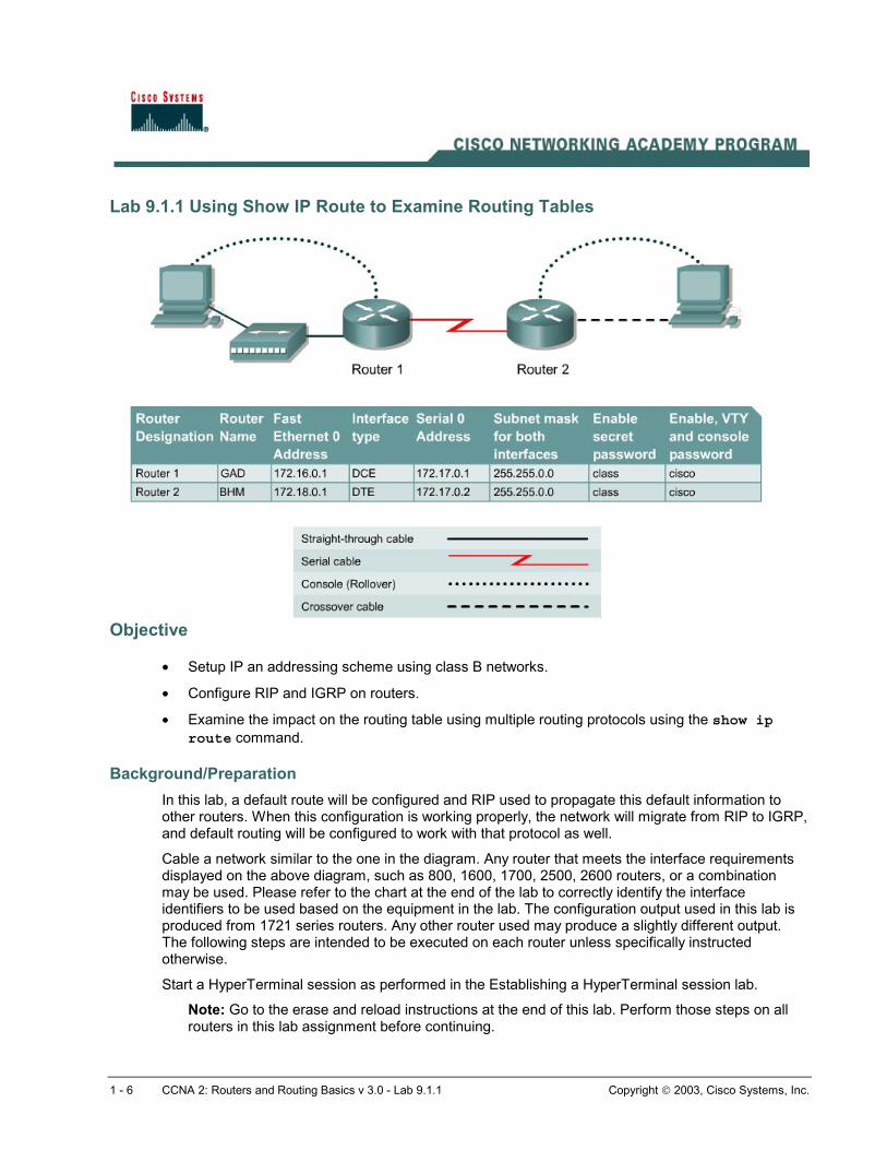
1 - 6 CCNA 2: Routers and Routing Basics v 3.0 - Lab 9.1.1 Copyright 2003, Cisco Systems, Inc.
Lab 9.1.1 Using Show IP Route to Examine Routing Tables
Objective
• Setup IP an addressing scheme using class B networks.
• Configure RIP and IGRP on routers.
• Examine the impact on the routing table using multiple routing protocols using the show ip route command.
Background/Preparation In this lab, a default route will be configured and RIP used to propagate this default information to other routers. When this configuration is working properly, the network will migrate from RIP to IGRP, and default routing will be configured to work with that protocol as well.
Cable a network similar to the one in the diagram. Any router that meets the interface requirements displayed on the above diagram, such as 800, 1600, 1700, 2500, 2600 routers, or a combination may be used. Please refer to the chart at the end of the lab to correctly identify the interface identifiers to be used based on the equipment in the lab. The configuration output used in this lab is produced from 1721 series routers. Any other router used may produce a slightly different output. The following steps are intended to be executed on each router unless specifically instructed otherwise.
Start a HyperTerminal session as performed in the Establishing a HyperTerminal session lab.
Note: Go to the erase and reload instructions at the end of this lab. Perform those steps on all routers in this lab assignment before continuing.

2 - 6 CCNA 2: Routers and Routing Basics v 3.0 - Lab 9.1.1 Copyright 2003, Cisco Systems, Inc.
Step 1 Configure the routers a. On the routers, enter the global configuration mode and configure the hostname as shown in the
chart. Then configure the console, virtual terminal, and enable passwords. If there is a problem doing this, refer to the Configuring Router Passwords lab. Next configure the interfaces according to the chart. If there is a problem doing this, refer to the Configuring Host Tables lab. Finally, configure RIP routing. This is covered in the Configuring RIP lab if help is needed. Do not forget to save the configurations to the startup configuration file.
Step 2 Configure the hosts with the proper IP address, subnet mask and default gateway
Step 3 Verify that the internetwork is functioning by pinging the FastEthernet interface of the other router
a. From the host attached to GAD, is it possible to ping the BHM router FastEthernet interface?
__________________________________________________________________________
b. From the host attached to BHM, is it possible to ping the GAD router FastEthernet interface?
__________________________________________________________________________
c. If the answer is no for either question, troubleshoot the router configurations to find the error. Then do the pings again until the answer to both questions is yes.
Step 4 Make sure that routing updates are being sent a. Type the command debug ip rip at the privileged EXEC mode prompt. Wait for at least 45
seconds.
b. Was there any output from the debug command? __________________________________
c. What did the output display? _________________________________________________
d. Stop the debug with no debug ip rip.
Step 5 Show the routing tables for each router a. Examine the routing table entries, using command show ip route command on each router.
b. What are the entries in the GAD routing table?
__________________________________________________________________________
c. What are the entries in the BHM routing table?
__________________________________________________________________________
Step 6 Enable IGRP routing on both routers a. Leave RIP enabled but enter router igrp 25 on both routers at the configuration prompt.
Enter the appropriate network statements for each router. GAD(config)#network 172.16.0.0 GAD(config)#network 172.17.0.0 BHM(config)#network 172.18.0.0 BHM(config)#network 172.17.0.0
b. On the router where debug ip rip was entered, now enter debug ip igrp events. Then wait at least two minutes.
c. What type of routing updates are being sent? _____________________________________

3 - 6 CCNA 2: Routers and Routing Basics v 3.0 - Lab 9.1.1 Copyright 2003, Cisco Systems, Inc.
d. Why are both protocols sending updates? ________________________________________
Step 7 Show the routing tables for each router again a. Examine the routing table entries, using command show ip route command on each router.
b. What are the entries in the GAD routing table?
__________________________________________________________________________
c. What are the entries in the BHM routing table?
__________________________________________________________________________
d. Why are the RIP routes not in the tables?
__________________________________________________________________________
e. What should be done in order for this network to be more efficient?
__________________________________________________________________________
Step 8 Add a second serial cable between routers a. Add a second serial cable between interface S1 on GAD to serial S1 on BHM. GAD is the DCE.
b. Configure the GAD router with the additional statements.
GAD(config)#interface Serial1 GAD(config-if)#ip address 172.22.0.1 255.255.0.0 GAD(config)#clockrate 56000 GAD(config)#no shutdown
c. Configure the BHM router with the additional statements.
BHM(config)#interface Serial1 BHM(config-if)#ip address 172.22.0.2 255.255.0.0 BHM(config)#no shutdown
d. On the BHM router remove the IGRP network statement network 172.18.0.0 so the router IGRP 25 should only contain the network 172.17.0.0 statement.
Step 9 Clear the routing tables on both routers a. Type the command clear ip route * at the privileged EXEC prompt on both routers. Wait at
least 90 seconds. Then type the command show ip route on both routers.
b. What types of routes are shown on GAD? ________________________________________
c. What types of routes are shown on BHM? ________________________________________
d. Why is this? _____________________________________________________________
Step 10 Use show ip route to see different routes by type a. Enter show ip route while connected to the GAD router.
b. What networks are displayed?
__________________________________________________________________________
c. What interface is directly connected? ___________________________________________

4 - 6 CCNA 2: Routers and Routing Basics v 3.0 - Lab 9.1.1 Copyright 2003, Cisco Systems, Inc.
d. Enter show ip route rip.
e. List the routes listed in the routing table: _________________________________________
f. What is the administrative distance? ____________________________________________
g. Enter show ip route while connected to the BHM router.
h. What networks are displayed? ________________________________________________
i. What interface is directly connected? ___________________________________________
j. Enter show ip route rip.
k. List the routes listed in the routing table: _________________________________________
l. If you saw none then that is correct, why? ________________________________________
m. Enter show ip route igrp
n. List the routes listed in the routing table: _________________________________________
o. What is the administrative distance? ____________________________________________
Upon completion of the previous steps, log off by typing exit and turn the router off.

1 - 5 CCNA 2: Routers and Routing Basics v 3.0 - Lab 9.1.2 Copyright 2003, Cisco Systems, Inc.
Lab 9.1.2 Gateway of Last Resort
Objective
• Configure RIP routing and add default routes (gateways) to the routers.
• Remove RIP and the default routes.
• Configure IGRP routing and add default routes (gateways) to the routers.
Background/Preparation This lab shows the purpose of the gateway of last resort, also known as the default gateway.
Cable a network similar to the one in the diagram. Any router that meets the interface requirements displayed on the above diagram, such as 800, 1600, 1700, 2500, and 2600 routers, or a combination may be used. Please refer to the chart at the end of the lab to correctly identify the interface identifiers to be used based on the equipment in the lab. The configuration output used in this lab is produced from 1721 series routers. Any other router used may produce a slightly different output. The following steps are intended to be executed on each router unless specifically instructed otherwise.
Start a HyperTerminal session as performed in the Establishing a HyperTerminal session lab.
Note: Go to the erase and reload instructions at the end of this lab. Perform those steps on all routers in this lab assignment before continuing.

2 - 5 CCNA 2: Routers and Routing Basics v 3.0 - Lab 9.1.2 Copyright 2003, Cisco Systems, Inc.
Step 1 Configure the routers a. On the routers, enter the global configuration mode and configure the hostname as shown in the
chart. Then configure the console, virtual terminal and enable passwords. If there is a problem doing this, refer to the Configuring Router Passwords lab. Next configure the interfaces according to the chart. If there is a problem doing this, refer to the Configuring Host Tables lab. Finally configure the RIP routing. This is covered in the Configuring RIP lab if help is needed. Do not forget to save the configurations to the startup configuration file.
Step 2 Configure the hosts with the proper IP address, subnet mask and default gateway
Step 3 Verify that the internetwork is functioning by pinging the FastEthernet interface of the other router
a. From the host attached to GAD, is it possible to ping the BHM router FastEthernet interface?
__________________________________________________________________________
b. From the host attached to BHM, is it possible to ping the GAD router FastEthernet interface?
__________________________________________________________________________
c. If the answer is no for either question, troubleshoot the router configurations to find the error. Then do the pings again until the answer to both questions is yes.
Step 4 Make sure that routing updates are being sent a. Type the command debug ip rip and the privileged exec mode prompt. Wait for at least 45
seconds.
b. Was there any output from the debug command? __________________________________
c. What did the output display? _________________________________________________
d. Type undebug all to turn off debugging.
Step 5 Show the routing tables for each router a. Examine the routing table entries, by using show ip route command on each router.
b. What are the entries in the GAD routing table?
__________________________________________________________________________
c. What are the entries in the BHM routing table?
__________________________________________________________________________
Step 6 Add the default route to the BHM router a. Enter the command ip route 0.0.0.0 0.0.0.0 172.17.0.1 at the configuration mode
prompt.
b. Type show ip route at the privileged exec mode.
c. What is the Gateway of last resort listed? ________________________________________
d. What does the gateway of last resort mean? ______________________________________
Step 7 Add the default route to the GAD router a. Enter the command ip route 0.0.0.0 0.0.0.0 172.17.0.2 at the configuration prompt.
b. Type show ip route at the privileged exec mode.

3 - 5 CCNA 2: Routers and Routing Basics v 3.0 - Lab 9.1.2 Copyright 2003, Cisco Systems, Inc.
c. What is the Gateway of last resort listed? ________________________________________
d. Are there any other new entries in the routing table? ________________________________
Step 8 Remove RIP routing from both routers a. To remove RIP routing type the no router rip command at the configuration mode prompt.
Then ping the FastEthernet 0 interface on the GAD router from the BHM router.
b. What were the results of the ping? _____________________________________________
c. Why was the ping successful? ________________________________________________
Step 9 Remove the default route from just the GAD router a. Remove the gateway of last resort on the GAD router by typing the no ip route 0.0.0.0
0.0.0.0 172.17.0.2 at the configuration mode prompt on the GAD router.
b. Type show ip route at the privileged exec mode.
c. What is the Gateway of last resort listed? ________________________________________
d. Why is the gateway gone? ___________________________________________________
e. Ping the FastEthernet 0 interface on the GAD router from the BHM router.
f. What were the results of the ping? _____________________________________________
g. Why was the ping successful? ________________________________________________
h. Ping the FastEthernet 0 interface on the BHM router from the GAD router.
i. What were the results of the pings? ____________________________________________
j. Why was the ping unsuccessful? ______________________________________________
k. Remove the gateway of last resort from the BHM router.
Step 10 Remove RIP routing from the routers and use IGRP instead a. Remove the RIP routing by using the no form of the RIP routing command. Then set up IGRP
routing using 30 as the AS number. Remember to wait for the routes to propagate to the other router.
b. Check the new routing protocol by typing show ip route at the privileged exec mode prompt. There should be two connected and IGRP route in the listing.
Step 11 Enter a default network entry on the BHM router a. Enter the command ip default-network 172.17.0.0 at the configuration mode prompt
b. Type the show ip route command at the privileged exec mode.
c. Is there a default route listed? ________________________________________________
Upon completion of the previous steps, log off by typing exit and turn the router off.

1 - 5 CCNA 2: Routers and Routing Basics v 3.0 - Lab 9.1.8 Copyright 2003, Cisco Systems, Inc.
Lab 9.1.8 Last Route Update
Objective
• Gather information about routing updates and routing protocols.
Background/Preparation Cable a network similar to the one in the diagram. Any router that meets the interface requirements displayed on the above diagram, such as. 800, 1600, 1700, 2500, 2600 routers, or a combination, may be used. Please refer to the chart at the end of the lab to correctly identify the interface identifiers to be used based on the equipment in the lab. The configuration output used in this lab is produced from 1721 series routers. Any other router used may produce a slightly different output. The following steps are intended to be executed on each router unless specifically instructed otherwise.
Start a HyperTerminal session as performed in the Establishing a HyperTerminal session lab.
Note: Go to the erase and reload instructions at the end of this lab. Perform those steps on all routers in this lab assignment before continuing.
Step 1 Configure the routers a. On the routers, enter the global configuration mode and configure the hostname as shown in the
chart. Then configure the console, virtual terminal, and enable passwords. If there is a problem doing this, refer to the Configuring Router Passwords lab. Next configure the interfaces according to the chart. If there is a problem doing this, refer to the Configuring Host Tables lab. Finally configure the RIP routing. This is covered in the Configuring RIP lab if help is needed. Do not forget to save the configurations to the startup configuration file.

2 - 5 CCNA 2: Routers and Routing Basics v 3.0 - Lab 9.1.8 Copyright 2003, Cisco Systems, Inc.
Step 2 Configure the hosts with the proper IP address, subnet mask and default gateway Step 3 Verify that the internetwork is functioning by pinging the FastEthernet interface of
the other router
a. From the host attached to GAD, is it possible to ping the BHM router FastEthernet interface?
__________________________________________________________________________
b. From the host attached to BHM, is it possible to ping the GAD router FastEthernet interface?
__________________________________________________________________________
c. If the answer is no for either question, troubleshoot the router configurations to find the error. Then do the pings again until the answer to both questions is yes.
Step 4 Make sure that routing updates are being sent a. Type the command debug ip rip at the privileged EXEC mode prompt. Wait for at least 45
seconds.
b. Was there any output from the debug command? __________________________________
c. Type undebug all to turn off debugging.
Step 5 Show the routing tables for each router a. Examine the routing table entries, using command show ip route command on each router.
Step 6 Check the routing table for a specific route (IOS version must be at least 12.x) a. From BHM privileged EXEC mode prompt enter show ip route 172.16.0.0.
b. When was the last update? __________________________________________________
c. When did BHM receive the last RIP update? ______________________________________
Wait five seconds and enter show ip route 172.16.0.0 a second time.
d. What has changed from first time? _____________________________________________
Wait five seconds and enter show ip route 172.16.0.0 a third time.
e. What has changed from second time? __________________________________________
f. What is the default update time for RIP? _________________________________________
Step 7. Check the ip rip database on the BHM router a. Type show ip rip database from the privileged EXEC mode prompt.
b. When was the last update? __________________________________________________
Wait five second and enter show ip rip database.
c. What has changed from the first time? __________________________________________
Wait five seconds and enter show ip rip database.
d. What has changed from the second time? ________________________________________
3 - 5 CCNA 2: Routers and Routing Basics v 3.0 - Lab 9.1.8 Copyright 2003, Cisco Systems, Inc.
Step 8 Configure IGRP using AS number 101 on all routers. Leave RIP on all routers
Step 9 From BHM enter show ip route a. List the routes shown in the routing table.
__________________________________________________________________________
b. When did BHM receive the last IGRP update? _____________________________________
Wait five seconds and enter show ip route.
c. What has changed from the first time? __________________________________________
Wait five seconds and enter show ip route.
d. What has changed from the second time? ________________________________________
e. What is the default update time for IGRP? ________________________________________
Step 10 Check the routing protocol on router BHM a. From the BHM privileged EXEC mode, enter show ip protocols.
b. What protocols are listed? ___________________________________________________
c. The next update is due in how many seconds for each protocol? _______________________
Upon completion of the previous steps, log off by typing exit and turn the router off.

1 - 4 CCNA 2: Routers and Routing Basics v 3.0 - Lab 9.2.6 Copyright 2003, Cisco Systems, Inc.
Lab 9.2.6 Troubleshooting Using Ping and Telnet
Objective • Use knowledge of OSI Layers 1, 2 and 3 to diagnose network configuration errors.
• Use ping and telnet utilities in testing.
Background/Preparation Cable a network similar to the one in the diagram. Any router that meets the interface requirements displayed on the above diagram, such as 800, 1600, 1700, 2500, 2600 routers, or a combination, may be used. Please refer to the chart at the end of the lab to correctly identify the interface identifiers to be used based on the equipment in the lab. The configuration output used in this lab is produced from 1721 series routers. Any other router used may produce a slightly different output. The following steps are intended to be executed on each router unless specifically instructed otherwise.
Start a HyperTerminal session as performed in the Establishing a HyperTerminal session lab.
Note: Work in teams of 2. Team member 1 should cable and configure the routers and workstations according to the chart. This will introduce some errors. Team member 2 should test the configuration using physical inspection, ping and Telnet.
Note: Go to the erase and reload instructions at the end of this lab. Perform those steps on all routers in this lab assignment before continuing.

2 - 4 CCNA 2: Routers and Routing Basics v 3.0 - Lab 9.2.6 Copyright 2003, Cisco Systems, Inc.
Step 1 Configure the routers a. On the routers, enter the global configuration mode and configure the hostname as shown in the
chart. Then configure the console, virtual terminal, and enable passwords. If there are problems doing this, refer to the Configuring Router Passwords lab. Next configure the interfaces and routing according to the chart. If there are problems doing this, refer to the Configuring Host Tables lab and the Configuring RIP lab. Make sure to copy the running-config to the startup-config on each router, so the configuration will not be lost if the router is power recycled.
Step 2 Configure the hosts with the proper IP address, subnet mask and default gateway a. Test the configuration by pinging all interfaces from each host. If the pinging is not successful go
on to Step 3.
Step 3 Check the connections a. Review the physical connections on the standard lab setup.
b. Check all physical devices, cables, and connections.
Step 4 Troubleshoot a. Troubleshoot induced network problems.
b. Use the commands ping and telnet to discover problems.
Step 5 List the findings a. Write down the problems as they are encountered.
b. Write down what was done to correct the problems.
c. Have the instructor verify that all problems were corrected.
Problem # Problem Discovered Solution Instructor Verification
1 2 3 4 5
Step 6 Perform the lab again with Team members 1 and 2 switching roles
Upon completion of the previous steps, log off by typing exit and turn the router off.

1 - 3 CCNA 2: Routers and Routing Basics v 3.0 - Lab 9.3.4 Copyright 2003, Cisco Systems, Inc.
Lab 9.3.4 Troubleshooting using Traceroute

2 - 3 CCNA 2: Routers and Routing Basics v 3.0 - Lab 9.3.4 Copyright 2003, Cisco Systems, Inc.
Objective Use the traceroute Cisco IOS command from source router to destination router. Use the tracert MS-DOS command from source workstation to destination router. Verify that the network-layer between source, destination and each router along the way is working properly. Retrieve information to evaluate the end-to-end path reliability.
Cable the network in the diagram. Any router that meets the interface requirements displayed on the above diagram such as 800, 1600, 1700, 2500, 2600 routers, or a combination, may be used. Please refer to the chart at the end of the lab to correctly identify the interface identifiers to be used based on the equipment in the lab. The configuration output used in this lab is produced from 1721 series routers. Any other router used may produce slightly different output. The following steps are intended to be executed on each router unless specifically instructed otherwise.
Start a HyperTerminal session as performed in the Establishing a HyperTerminal session lab.
Erase and reload all routers in this lab assignment before continuing. If there are problems in accomplishing this, go to lab 4.2.6 and use those erase and reload instructions.
Step 1 Configure the Gadsden and Birmingham routers
a. On the routers, enter the global configuration mode and configure the hostname as shown in the chart. Then configure the console, virtual terminal and enable passwords. If there are problems doing this, refer to the Configuring router passwords lab. Next configure the interfaces and routing according to the chart. If there are problems doing this, refer to the Configuring Host Tables lab and the Configuring RIP lab. Make sure to copy the running-config to the startup-config on each router so the configuration will not be lost if the router is power recycled.
b. This lab requires that IP hostnames are configured.
c. Verify the routers configurations by performing a show running-config on each router. If not correct, fix any configuration errors and verify.
Step 2 Configure the workstations with appropriate IP address subnet mask and default gateway
Step 3 Ping from the workstations a. From a Windows host click on Start > Programs > Accessories> MS-DOS. This will open a
Command Prompt window. (If this not the correct location see the instructor for the proper location on this computer.)
b. To test that the TCP/IP stack and default gateway on the workstation are configured and working properly, use the MS DOS window to ping the routers by issuing the following commands:
C:\>ping 192.168.14.1
The ping should respond with successful results. If not, check the configurations on the host and directly connected router.
Step 4 Test Layer 3 connectivity Using the command prompt enter ping and the IP address of all routers interfaces.
This will test Layer 3 connectivity between the workstation and the routers.
a. Is the output from the workstation ping command the same as the output from the ping command from a router?
__________________________________________________________________________

3 - 3 CCNA 2: Routers and Routing Basics v 3.0 - Lab 9.3.4 Copyright 2003, Cisco Systems, Inc.
Step 5 Login to the router in user mode a. Login to the Gadsden router, stay at the user exec prompt.
Step 6 Discover the trace options. a. Enter trace at the router prompt.
b. What did the router respond with? _____________________________________
Step 7 Use the traceroute command a. Enter traceroute ip xxx.xxx.xxx.xxx where xxx.xxx.xxx.xxx is the IP address of the
target destination.
Note: Use one of the end routers and trace IP to the other end host. The router will respond with:
GAD#traceroute 192.168.16.2 Type escape sequence to abort. Tracing the route to 192.168.16.2 1 BHM (192.168.15.2) 16 msec 16 msec 16 msec 2 192.168.16.2 16 msec 16 msec 12 msec GAD#
If the output is not successful, check the router and host configurations.
Step 8 Continue using traceroute Repeat Step 5 with all other routers on the network.
Step 9 Use the trace command from a workstation. a. From the console workstation click on Start > Programs > Command Prompt. An MS-DOS
Command Prompt window will open up.
b. Enter tracert and the same IP address used in Step 5.
c. The first hop is the default gateway or the near side router interface on the LAN that the workstation is connected to. List the host name and IP address of the router that the ICMP packet was routed through.
Host Name IP Address
d. There is one more entry in the output of the tracert command when the trace is from the computer command prompt to the target host.
Why? __________________________________________________________________
Upon completion of the previous steps logoff by typing exit and turn the router off.

1 - 6 CCNA 2: Routers and Routing Basics v 3.0 - Lab 9.3.5 Copyright 2003, Cisco Systems, Inc.
Lab 9.3.5 Troubleshooting Routing Issues with show ip route and show ip protocols
Objective • Use the show ip route and show ip protocol commands to diagnose a routing
configuration problem.
Background/Preparation Cable a network similar to the one in the diagram. Any router that meets the interface requirements displayed on the above diagram, such as 800, 1600, 1700, 2500, 2600 routers, or a combination, may be used. Please refer to the chart at the end of the lab to correctly identify the interface identifiers to be used based on the equipment in the lab. The configuration output used in this lab is produced from 1721 series routers. Any other router used may produce a slightly different output. The following steps are intended to be executed on each router unless specifically instructed otherwise.
Start a HyperTerminal session as performed in the Establishing a HyperTerminal session lab.
Note: Go to the erase and reload instructions at the end of this lab. Perform those steps on all routers in this lab assignment before continuing.

2 - 6 CCNA 2: Routers and Routing Basics v 3.0 - Lab 9.3.5 Copyright 2003, Cisco Systems, Inc.
Step 1 Configure the hostname, passwords and interfaces on the Gadsden router a. On the Gadsden router, enter the global configuration mode and configure the hostname as
shown in the chart. Then configure the console, virtual terminal and enable passwords. If there is a problem doing this, refer to the Configuring Router Passwords lab. Configure interfaces as shown in the table.
Step 2 Configure the routing protocol on the Gadsden router a. Go to the proper command mode and enter the following:
GAD(config)#router rip GAD(config-router)#network 192.168.1.0 GAD(config-router)#network 192.168.2.0 GAD(config-router)#exit GAD(config)#exit
Step 3 Save the Gadsden router configuration GAD#copy running-config startup-config Destination filename [startup-config]? [Enter]
Step 4 Configure the hostname and passwords on the Birmingham router a. On the Birmingham router, enter the global configuration mode and configure the hostname as
shown in the chart. Then configure the console, virtual terminal and enable passwords. Finally, configure the interfaces on each router.
Step 5 Configure the routing protocol on the Birmingham router a. Go to the proper command mode and enter the following:
BHM(config)#router rip BHM(config-router)#network 192.168.2.0 BHM(config-router)#network 192.168.1.0 BHM(config-router)#exit BHM(config)#exit
Step 6 Save the Birmingham router configuration BHM#copy running-config startup-config Destination filename [startup-config]? [Enter]
Step 7 Verify that the internetwork is functioning by pinging the FastEthernet interface of the other router
a. From GAD, is it possible to ping the BHM router FastEthernet interface? _________________
b. From BHM, is it possible to ping the GAD router FastEthernet interface? _________________
Step 8 Examine the routing table a. After an unsuccessful ping, check the routing table with the show ip route command. From
the Gadsden router, type the following:

3 - 6 CCNA 2: Routers and Routing Basics v 3.0 - Lab 9.3.5 Copyright 2003, Cisco Systems, Inc.
GAD#show ip route
b. Is there a route to the Birmingham Ethernet LAN? _____________________
Step 9 Examine the routing protocol status a. After examining the routing tables, it is discovered that there is no route to the Birmingham
Ethernet LAN. So use the show ip protocol command to view the routing protocol status. From the Birmingham router, type the following: BHM#show ip protocol
b. What networks is RIP routing? _____________________ _____________________
c. Are these the correct networks? _____________________
Step 10 Change the configuration to route correct networks a. After examining the show ip protocol command results, it is noticed that the network on the
Ethernet LAN is not being routed. After examining it further, it is found that there is a network that does not belong has been configured to be advertised. It is decided this is a typo, and it is necessary to correct it. Enter the router RIP configuration mode and make the appropriate changes. From the Birmingham router, type the following:
BHM#configure terminal BHM(config)#router rip BHM(config-router)#no network 192.168.1.0 BHM(config-router)#network 192.168.3.0 BHM(config-router)#^Z
Step 11 Confirm RIP is routing the correct networks a. Now confirm the new statement corrected the RIP configuration problem. So again type the
show ip protocol command to observe what networks are being routed. b. From the Birmingham router, type the following:
BHM#show ip protocol
c. What networks is RIP routing? _____________________ _____________________
d. Are these the correct networks? _____________________
Step 12 Verify the routing table a. Now having confirmed that the configuration problem is corrected, verify that the proper routes
are now in the routing table. So again issue the show ip route command to verify that the router now has the proper route.
b. From the Gadsden router, type the following:
GAD#show ip route
c. Is there a route to the Birmingham LAN? _____________________

4 - 6 CCNA 2: Routers and Routing Basics v 3.0 - Lab 9.3.5 Copyright 2003, Cisco Systems, Inc.
Step 13 Verify connectivity between Gadsden router and host in Birmingham a. Use the ping command to verify connectivity from Gadsden router to a host in Birmingham.
b. From the Gadsden router, type the following: GAD#ping host-ip
For example for host with IP Address, type the following: GAD#ping 192.168.3.2
c. Was the ping successful? _____________________
Upon completion of the previous steps, log off by typing exit and turn the router off.

1 - 5 CCNA 2: Routers and Routing Basics v 3.0 - Lab 11.2.1a Copyright 2003, Cisco Systems, Inc.
Lab 11.2.1a Configuring Standard Access Lists
Objective • Configure, and apply a standard ACL to permit or deny specific traffic.
• Test the ACL to determine if the desired results were achieved.
Background/Preparation Cable a network similar to the one in the diagram. Any router that meets the interface requirements displayed on the above diagram, such as 800, 1600, 1700, 2500, 2600 routers, or a combination, may be used. Please refer to the chart at the end of the lab to correctly identify the interface identifiers to be used based on the equipment in the lab. The configuration output used in this lab is produced from 1721 series routers. Any other router used may produce a slightly different output. The following steps are intended to be executed on each router unless specifically instructed otherwise.
Start a HyperTerminal session as performed in the Establishing a HyperTerminal session lab.
Note: Go to the erase and reload instructions at the end of this lab. Perform those steps on all routers in this lab assignment before continuing.

2 - 5 CCNA 2: Routers and Routing Basics v 3.0 - Lab 11.2.1a Copyright 2003, Cisco Systems, Inc.
Step 1 Configure the hostname and passwords on the Gadsden router a. On the Gadsden router, enter the global configuration mode and configure the hostname as
shown in the chart. Then configure the console, virtual terminal and enable passwords. Configure the FastEthernet interface on the router according to the chart.
Step 2 Configure the hosts on the Ethernet segment a. Host 1
IP address 192.168.14.2 Subnet mask 255.255.255.0 Default gateway 192.168.14.1
b. Host 2
IP address 192.168.14.3 Subnet mask 255.255.255.0 Default gateway 192.168.14.1
Step 3 Save the configuration information from the privileged EXEC command mode GAD#copy running-config startup-config
Step 4 Confirm connectivity by pinging the default gateway from both hosts a. If the pings are not successful, correct the configuration and repeat until they are successful.
Step 5 Prevent access to the Ethernet interface from the hosts a. Create an access list that will prevent access to FastEthernet 0 from the 192.168.14.0 network.
b. At the router configuration prompt type the following command: GAD(config)#access-list 1 deny 192.168.14.0 0.0.0.255 GAD(config)#access-list 1 permit any
c. Why is the second statement needed? So that hosts from other networks are allowed_________
Step 6 Ping the router from the hosts a. Were these pings successful? __Yes______________________________________________
b. If they were, why? __Access list has not been applied to the interface_______________________________________________________
Step 7 Apply the Access list to the interface a. At the FastEthernet 0 interface mode prompt type the following:
GAD(config-if)#ip access-group 1 in
Step 8 Ping the router from the hosts a. Were these pings successful? __No______________________________________________
b. If they were, why? __Not applicable_______________________________________________________
Step 9 Create a new access list a. Now create an access list that will prevent the even numbered hosts from pinging but permit the
odd numbered one.

3 - 5 CCNA 2: Routers and Routing Basics v 3.0 - Lab 11.2.1a Copyright 2003, Cisco Systems, Inc.
b. What will that access list look like? Finish this command with an appropriate comparison IP address (aaa.aaa.aaa.aaa) and wildcard mask (www.www.www.www):
ip access-list 2 permit aaa.aaa.aaa.aaa www.www.www.www
c. Why was it not necessary to have the permit any statement at the end this time?
__Becaues we only allow odd host from 192.168.14.0 and denied all others________________________________________________________________________
Step 10 Apply access list to the proper router interface a. First remove the old access list application by typing no ip access-group 1 in at the
interface configuration mode.
b. Apply the new access list by typing ip access-group 2 in
Step 11 Ping the router from each hosts a. Was the ping from host 1 successful? _No__________________________________________
b. Why or why not? __Even numbered host________________________________________________________
c. Was the ping from host 2 successful? __Yes_________________________________________
d. Why or why not? ____Odd numbered host______________________________________________________
Upon completion of the previous steps, logoff by typing exit. Turn the router off.

1 - 4 CCNA 2: Routers and Routing Basics v 3.0 - Lab 11.2.1b Copyright 2003, Cisco Systems, Inc.
Lab 11.2.1b Standard ACLs
Objective Plan, configure, and apply a standard ACL to permit or deny specific traffic and test the ACL to determine if the desired results were achieved.
Scenario The company home office in Gadsden (GAD) provides services to branch offices such as the Birmingham (BHM) office. These offices have some minor security and performance concerns. Standard ACL need to be implemented as a simple and effective tool to control traffic

2 - 4 CCNA 2: Routers and Routing Basics v 3.0 - Lab 11.2.1b Copyright 2003, Cisco Systems, Inc.
Infrastructure Host #3 represents the kiosk station that needs to have its access limited to the local network.
Host #4 represents another host in the Birmingham office Loopback 0 on the GAD router represents the Internet.
Step 1 Basic Router Interconnection a. Interconnect the routers as shown in the diagram.
Step 2 Basic Configuration a. The router may contain configurations from a previous use. For this reason, erase the startup
configuration and reload the router to remove any residual configurations. Using the information previously in the tables, setup the router and host configurations and verify reachablilty by pinging all systems and routers from each system.
b. To simulate the Internet, add the following configuration to the GAD router. GAD(config)#interface loopback0 GAD(config-if)#address 172.16.1.1 255.255.255.0 GAD(config-if)#exit GAD(config)#router rip GAD(config-router)#network 172.16.0.0 GAD(config-if)#^z
Step 3 Establish Access List Requirements a. The kiosk station (host 3) needs to have its access limited to the local network. It is determined
that a standard access list needs to be created to prevent traffic from this host from reaching any other networks. The access control list should block traffic from this host and not affect other traffic from this network. Using a standard IP ACL is adequate for as it filters based on the source address to any destination.
What source address of the kiosk? ____________________________
Step 4 Plan the Access List Requirements a. As with any project, the most important part of the process is the planning. First, the information
needed to create the ACL need to be defined. An access list is made up a series of ACL statements. Each of these statements adds sequentially to the ACL. Since the list will consist of more than one statement, the order of the statement needs to be planned carefully.
b. It has been determined that for this ACL will require 2 logical steps. Each of these steps can be accomplished with one statement each. As a planning tool, a text editor like Notepad can be used to organize the logic and then write the list. In the text editor enter the logic by typing: ! stop traffic from host 3 ! permit all other traffic

3 - 4 CCNA 2: Routers and Routing Basics v 3.0 - Lab 11.2.1b Copyright 2003, Cisco Systems, Inc.
c. From this logic the actual ACL will be written. Using the tables below, document the information for each statement.
stop traffic from host 3 List # permit or deny Source address Wildcard mask
permit all other traffic List # permit or deny Source address Wildcard mask
d. What would be the result of not including a statement at to permit all other source addresses?
_________________________________________________________________________________________
e. What would be the result of reversing the order of the 2 statements in the list?
_________________________________________________________________________________________
f. Why are both statements using the same ACL number?
_________________________________________________________________________________________
g. The final step in the planning process is to determine the best location for the access list and the direction the list should be applied. Examine the internetwork diagram and choose the appropriate interface and direction. Document this in the table below:
Router Interface Direction
Step 5 Write and Apply the ACL a. Using the previously constructed logic and information of the access list, complete the
commands in the text editor. The list syntax should look similar to:
! stop traffic from host 3
access-list #deny address wildcard
! permit all other traffic
access-list #permit address wildcard
b. Add to this text file the configuration statements to apply the list.
The configuration statements take the form of:
interface type #/#
ip access-group #{in, out}

4 - 4 CCNA 2: Routers and Routing Basics v 3.0 - Lab 11.2.1b Copyright 2003, Cisco Systems, Inc.
c. Now the text file configuration needs to be applied to the router. Enter the configuration mode on the appropriate router and copy and paste the configuration. Observe the CLI display to ensure no errors were encountered.
Step 6 Verify the ACL Now that the ACL is completed, the ACL needs to be confirmed and tested.
a. First step is to check the list to see if it was configured properly in the router. To check the ACL logic use the show access-list command. Record the output
_________________________________________________________________________________________
_________________________________________________________________________________________
_________________________________________________________________________________________
b. Next, verify that the access list was applied to the proper interface and in the correct direction. To do this examine the interface with the show ip interface command. Look at the output from each interface and record the lists applied to the interface.
Interface ________________________________________________________________
Outgoing access list is ____________________________________________________
Inbound access list is ____________________________________________________
c. Finally, test the functionality of the ACL by trying to send packets from the source host and verify that is to be permitted or denied as appropriate. In this case, ping will be used to test this.
[ ] verify that host 3 CAN ping host 4
[ ] verify that host 3 CANNOT ping host 1
[ ] verify that host 3 CANNOT ping host 2
[ ] verify that host 3 CANNOT ping GAD Fa0/0
[ ] verify that host 3 CANNOT ping GAD LO0
[ ] verify that host 4 CAN ping host 1
[ ] verify that host 4 CAN ping host 2
[ ] verify that host 4 CAN ping GAD Fa0/0
[ ] verify that host 4 CAN ping GAD LO0
Step 7 Document the ACL a. As a part of all network management, documentation needs to be created. Using the text file
created for the configuration, add additional comments. This file should also contain output from the show access-list and the show ip interface commands.
b. The file should be saved with other network documentation. The file naming convention should reflect the function of the file and the date of implementation.
c. That should complete the ACL project.
d. Once finished, erase the start-up configuration on routers, remove and store the cables and adapter. Also logoff and turn the router off.

1 - 5 CCNA 2: Routers and Routing Basics v 3.0 - Lab 11.2.2a Copyright 2003, Cisco Systems, Inc.
Lab 11.2.2a Configuring Extended Access Lists
Objective • Configure, and apply an extended ACL to permit or deny specific traffic.
• Test the ACL to determine if the desired results were achieved.
Background/Preparation Cable a network similar to the one in the diagram. Any router that meets the interface requirements displayed on the above diagram, such as 800, 1600, 1700, 2500, 2600 routers, or a combination, may be used. Please refer to the chart at the end of the lab to correctly identify the interface identifiers to be used based on the equipment in the lab. The configuration output used in this lab is produced from 1721 series routers. Any other router used may produce a slightly different output. The following steps are intended to be executed on each router unless specifically instructed otherwise.
Start a HyperTerminal session as performed in the Establishing a HyperTerminal session lab.
Note: Go to the erase and reload instructions at the end of this lab. Perform those steps on all routers in this lab assignment before continuing.
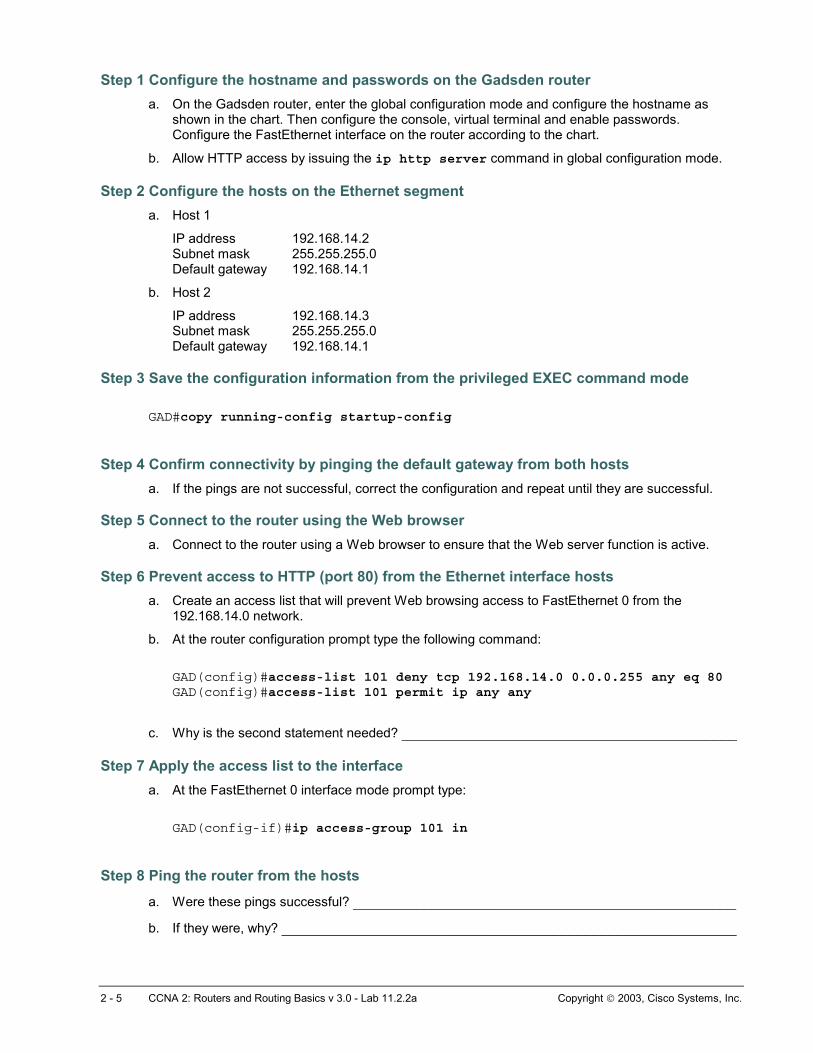
2 - 5 CCNA 2: Routers and Routing Basics v 3.0 - Lab 11.2.2a Copyright 2003, Cisco Systems, Inc.
Step 1 Configure the hostname and passwords on the Gadsden router a. On the Gadsden router, enter the global configuration mode and configure the hostname as
shown in the chart. Then configure the console, virtual terminal and enable passwords. Configure the FastEthernet interface on the router according to the chart.
b. Allow HTTP access by issuing the ip http server command in global configuration mode.
Step 2 Configure the hosts on the Ethernet segment a. Host 1
IP address 192.168.14.2 Subnet mask 255.255.255.0 Default gateway 192.168.14.1
b. Host 2
IP address 192.168.14.3 Subnet mask 255.255.255.0 Default gateway 192.168.14.1
Step 3 Save the configuration information from the privileged EXEC command mode GAD#copy running-config startup-config
Step 4 Confirm connectivity by pinging the default gateway from both hosts a. If the pings are not successful, correct the configuration and repeat until they are successful.
Step 5 Connect to the router using the Web browser a. Connect to the router using a Web browser to ensure that the Web server function is active.
Step 6 Prevent access to HTTP (port 80) from the Ethernet interface hosts a. Create an access list that will prevent Web browsing access to FastEthernet 0 from the
192.168.14.0 network.
b. At the router configuration prompt type the following command:
GAD(config)#access-list 101 deny tcp 192.168.14.0 0.0.0.255 any eq 80 GAD(config)#access-list 101 permit ip any any
c. Why is the second statement needed? __________________________________________
Step 7 Apply the access list to the interface a. At the FastEthernet 0 interface mode prompt type:
GAD(config-if)#ip access-group 101 in
Step 8 Ping the router from the hosts a. Were these pings successful? ________________________________________________
b. If they were, why? _________________________________________________________

3 - 5 CCNA 2: Routers and Routing Basics v 3.0 - Lab 11.2.2a Copyright 2003, Cisco Systems, Inc.
Step 9 Connect to the router using the web browser a. Was the browser able to connect? _____________________________________________
Step 10 Telnet to the router from the hosts a. Were you able to Telnet successfully? __________________________________________
b. Why or why not? __________________________________________________________
Upon completion of the previous steps, logoff by typing exit. Turn the router off.
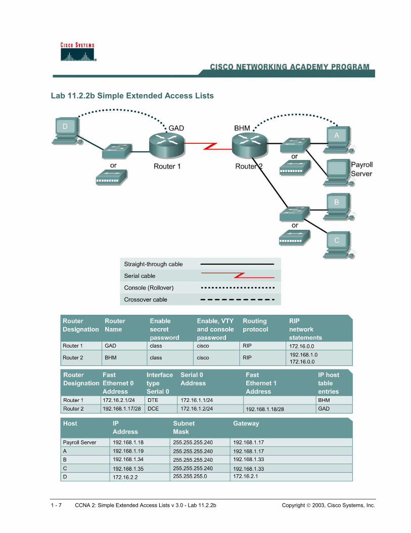
1 - 7 CCNA 2: Simple Extended Access Lists v 3.0 - Lab 11.2.2b Copyright 2003, Cisco Systems, Inc.
Lab 11.2.2b Simple Extended Access Lists

2 - 7 CCNA 2: Simple Extended Access Lists v 3.0 - Lab 11.2.2b Copyright 2003, Cisco Systems, Inc.
Objective In this lab, configuring extended access lists to filter network to network, host to network, and network to host traffic.
Scenario A marketing company has two locations. The main site is in Birmingham (BHM) and the branch site is in Gadsden (GAD). The telecommunication administrator for both sites needs to plan and implement access control lists for security and performance. At the Birmingham site, there are two groups of network users. These groups are an Administrative group and a Production group and each are on separate networks. Both networks are interconnected with a router.
The Gadsden site is a stub network and only has a LAN connected to it.
Step 1 Basic Router and Host Configurations a. Interconnect the routers and hosts as shown in the diagram. Configure all router basics such as
hostname, enable password, telnet access, router interfaces. Use the preceding diagram and tables for reference.
b. The configurations on each router should be as follows:
BHM#show running-config <Output Omitted> hostname BHM ! enable secret class ! interface FastEthernet0 ip address 192.168.1.17 255.255.255.240 ! interface Serial0 ip address 172.16.1.2 255.255.255.0 clock rate 56000 ! interface FastEthernet0/1 ip address 192.168.1.33 255.255.255.240 ! router rip network 172.16.0.0 network 192.168.1.0 ! line vty 0 4 password cisco login ! end
BHM# GAD#show running-config <Output Omitted> ! hostname GAD ! enable password class ! interface FastEthernet0 ip address 172.16.2.1 255.255.255.0 !

3 - 7 CCNA 2: Simple Extended Access Lists v 3.0 - Lab 11.2.2b Copyright 2003, Cisco Systems, Inc.
interface Serial0 ip address 172.16.1.1 255.255.255.0 ! router rip network 172.16.0.0 ! line vty 0 4 password cisco login ! no scheduler allocate end GAD#
c. Configure the hosts with the appropriate information using the information previously defined. Before applying any type of access list, it is important to verify reachability between systems.
Verify reachability by pinging all systems and routers from each system.
d. All hosts should be able to ping each other and the router interfaces. If pings to some interfaces are not successful, the problem will need to be located and corrected. Always verify the Physical layer connections, as they seem to be the more common source of connectivity problems. Next, verify the router interfaces. Make sure they are not shutdown, improperly configured, and that RIP is correctly configured. Finally, remember that along with valid IP addresses, hosts must also have default gateways specified.
e. Now that the infrastructure is in place, it is time to begin securing the internetwork.
Step 2 Prevent the Production Users from Accessing the Gadsden Network a. Company policy specifies that only the Administrative group should have access to the Gadsden
site. The Production group should be restricted from accessing that network.
b. Configure an extended access list to allow the Administrative group access to the Gadsden site. The production group should not have access to the Gadsden site.
c. After careful analysis, it is decided that it would be best to use an extended access list and apply it to the outgoing S0 interface on the BHM router.
Note: Remember that when the access list is configured, each statement in the list is processed by the router in the order it was created. It is not possible to reorder an access list, skip statements, edit statements, or delete statements from a numbered access list. For this reason, it may be beneficial to create the access-list in a text editor such as Notepad and then paste the commands to the router, instead of being typed in directly on a router.
d. Enter the following: BHM#conf terminal Enter configuration commands, one per line. End with CNTL/Z. BHM(config)#access-list 100 deny ip 192.168.1.32 0.0.0.15 172.16.2.0 0.0.0.255
e. This statement defines an extended access list called “100”. It will deny ip access for any users
on the 192.168.1.32 – 192.168.1.47 network if they are trying to access network 172.16.2.0. Although a less specific access list could be defined, this access list could allow the production users to access other sites (if available) through the S0 interface.
f. Remember that there is an implicit deny all at the of every access list. We must now make sure to let the administrative group access the Gadsden network. Although we could be more restrictive, we will simply let any other traffic through. Enter the following statement:

4 - 7 CCNA 2: Simple Extended Access Lists v 3.0 - Lab 11.2.2b Copyright 2003, Cisco Systems, Inc.
BHM(config)#access-list 100 permit ip any any
g. Now we need to apply the access list to an interface. We could apply the list to any incoming traffic going to the production network Fa0/1 interface. However, if there were a great deal of traffic between the administrative network and the production network, the router would have to check every packet. There is concern that this would add unwanted overhead to the router. Therefore the access list is applied to the any outgoing traffic going through the BHM router S0 interface.
Enter the following: BHM(config)#interface s0 BHM(config-if)#ip access-group 100 out
h. Verify the syntax of the access-list with the show running-config command. The following lists the valid statements that should be in the configuration. interface Serial0 ip access-group 100 out <Output Omitted> access-list 100 deny ip 192.168.1.32 0.0.0.15 172.16.2.0 0.0.0.255 access-list 100 permit ip any any
i. Another valuable command is the show access-lists command. The following is a sample output. BHM#show access-lists Extended IP access list 100 deny ip 192.168.1.32 0.0.0.15 172.16.2.0 0.0.0.255 permit ip any any
j. The show access-lists command also displays counters, indicating how many times the list has been used. No counters are listed here since we haven’t attempted to verify it yet.
Note: Use the clear access-list counters command to restart the access list counters k. Now test the access list by verifying reachability to the Gadsden network by the administrative
and production hosts.
Can the production host (B) ping the Gadsden host (D)? ___No________________________________
Can the production host (C) ping the Gadsden host (D)? ___No_______________________________
Can the administrative host (A) ping the Gadsden host (D)? __Yes______________________________
Can the production host (B) ping the administration host (A)? __Yes____________________________
Can the production host (B) ping the Gadsden router Serial interface? __Yes___________________
l. The production hosts (B) and (C) should be able to ping the administrative host (A) and Gadsden router Serial interface. However, they should not be able to ping the Gadsden host (D). The router should return a reply message to the host stating “Destination net unreachable”.
Issue the show access-lists command. How many matches are there? ________________

5 - 7 CCNA 2: Simple Extended Access Lists v 3.0 - Lab 11.2.2b Copyright 2003, Cisco Systems, Inc.
Note: The show access-lists command displays the number of matches per line. Therefore the number of deny matches may seem odd until it is realized that the pings matched the deny statement and the permit statement.
m. To help understand how the access list is operating, keep periodically issuing the show access-lists command.
Step 3 Allow a Production User Access to the Gadsden Network a. A call is received from a user in the production group (B). They are responsible for exchanging
certain files between the production network and the Gadsden network. The extended access list needs to be altered to allow them access to the Gadsden network, while denying everyone else on the production network.
b. Configure an extended access-list to allow that user access to Gadsden.
c. Unfortunately, it is not possible to reorder an access list, skip statements, edit statements, or delete statements from a numbered access list. With numbered access lists, any attempt to delete a single statement results in the entire list’s deletion.
d. Therefore the initial extended access list needs too be deleted and a new one created. To delete access-list 100, enter the following: BHM#conf t Enter configuration commands, one per line. End with CNTL/Z. BHM(config)#no access-list 100
Verify that it has been deleted with the show access-lists command.
e. Now create a new extended access list. Always filter from the most specific to the most generic. Therefore the first line of the access list should allow the production host (B) access to the Gadsden network. The remainder of the access-list should be the same as the previous we had entered.
f. To filter the production host (B) the first line of the access list should be as follows: BHM(config)#access-list 100 permit ip host 192.168.1.34 172.16.2.0 0.0.0.255
Therefore, the access list permits the production host (B) access to the Gadsden network.
g. Now deny all of the remaining production hosts access to the Gadsden network and permit any on else. Refer to the previous step for the next two lines of the configuration.
The show access-list command would display output similar to the following:
BHM#show access-lists Extended IP access list 100 permit ip host 192.168.1.34 172.16.2.0 0.0.0.255 deny ip 192.168.1.32 0.0.0.15 172.16.2.0 0.0.0.255 permit ip any any BHM#
h. Now test the access list by verifying reachability to the Gadsden network by the administrative and production hosts.
Can the production host (B) ping the Gadsden host (D)? ___Yes________________________________
Can the production host (C) ping the Gadsden host (D)? ___No________________________________

6 - 7 CCNA 2: Simple Extended Access Lists v 3.0 - Lab 11.2.2b Copyright 2003, Cisco Systems, Inc.
The production host (B) should now be able to ping the Gadsden host (D). However, all other production hosts (C) should not be able to ping the Gadsden host (D). Again, the router should return a reply message to the host stating “Destination net unreachable” for host (C).
Step 4 Allow Gadsden Users Access to the Administration Payroll Server a. The administration group houses the payroll server. Users from the Gadsden site need FTP and
HTTP access the payroll server from time to time to upload and download payroll reports.
b. Configure an extended access-list to allow users from the Gadsden site FTP, HHTP access to the payroll server only. It is decided to also allow ICMP access for them to ping the server. Gadsden users should not be able to ping any other host on the Administration network.
c. We do not want unnecessary traffic between the sites therefore it is decided to configure an extended access list on the Gadsden router.
d. I was anticipated that privileged EXEC access to the Gadsden would be required from time to time. That is why Telnet access to it is configured. Otherwise travel would be required to the Gadsden site to configure it.
e. Telnet to the Gadsden router from the Birmingham router and enter enable mode. Troubleshoot as necessary.
Note: A common pitfall when configuring access lists on remote routers is to inadvertently “lock yourself” out. This is not a big problem when the router is physically located local. However, this could be a huge problem if the router is physically located in another geographical location.
f. For this reason, it is strongly suggest that the reload in 30 command be issued on the remote router. This would automatically reload the remote router within 30 minutes of issuing the command. Therefore, if the administrator was locked out, it would eventually reload to the previous configuration, allowing access to the router again. Use the reload cancel command to deactivate the pending reload.
g. Configure an extended access list to allow FTP access to the payroll server. The access list statement should be similar to the following: GAD(config)#access-list 110 permit tcp any host 192.168.1.18 eq ftp
This line will permit any host from the Gadsden network FTP access to the payroll server at address 192.168.1.18.
What could we have defined instead of using the keyword “any”?
_________________________________________________________________________________________
What could we have defined instead of using the keyword “host”?
_________________________________________________________________________________________
What could we have defined instead of using the keyword “ftp”?
_________________________________________________________________________________________
h. Now configure the next line of the access list to permit HTTP access to the payroll server. The access list statement should be similar to the following: GAD(config)#access-list 110 permit tcp any host 192.168.1.18 eq http
This line will permit any host from the Gadsden network FTP access to the payroll server at address 192.168.1.18.

7 - 7 CCNA 2: Simple Extended Access Lists v 3.0 - Lab 11.2.2b Copyright 2003, Cisco Systems, Inc.
What else could we have defined instead of using the keyword “http”?
_________________________________________________________________________________________
i. Now configure the next line of the access list to permit ICMP access to the payroll server. The access list statement should be similar to the following: GAD(config)#access-list 110 permit icmp any host 192.168.1.18
This line will permit any host from the Gadsden network to ping the payroll server at address 192.168.1.18.
j. Finally, no Gadsden user should be able access any other host on the Administration network. Although it is not required, it is always a good idea to include a deny statement. Adding the statement is a good reminder and makes it easier to “read” the access list. The access list statement should be similar to the following: GAD(config)#access-list 110 deny ip any 192.168.1.16 0.0.0.15
k. Now we need to apply the access list to an interface. To reduce unwanted WAN traffic, it is decided to apply the access list to the any outgoing traffic going through the Gadsden routers S0 interface.
Enter the following: GAD(config)#interface s0 GAD(config-if)#ip access-group 110 out
l. Now test the access list by verifying reachability to the payroll server by a Gadsden host (D).
Can the Gadsden host (D) ping the payroll server? ________________________________________
Can the Gadsden host (D) ping the host (A)? _____________________________________________
The Gadsden host should be able to ping the payroll server only. The router should return the “Destination net unreachable” when it tries to ping the administrative host (D).
Step 5 Document the ACL a. As a part of all network management, documentation needs to be created. Using the text file
created for the configuration, add additional comments. This file should also contain output from the show access-list and the show ip interface commands.
b. The file should be saved with other network documentation. The file naming convention should reflect the function of the file and the date of implementation.
c. That should complete this extended ACL lab.
d. Once finished, erase the start-up configuration on routers, remove and store the cables and adapter. Also logoff and turn the router off.

1 - 6 CCNA 3: Switching Basics and Intermediate Routing v 3.0 - Lab 2.3.1 Copyright 2003, Cisco Systems, Inc.
Lab 2.3.1 Configuring the OSPF Routing Process
Objective • Setup an IP addressing scheme for OSPF area 0.
• Configure and verify Open Shortest Path First (OSPF) routing.
Background/Preparation Cable a network similar to the one shown in the diagram. Any router that meets the interface requirements displayed on the above diagram may be used. For example, router series 800, 1600, 1700, 2500, and 2600 or any such combination can be used. Please refer to the chart at the end of the lab to correctly identify the interface identifiers to be used based on the equipment in the lab. The configuration output used in this lab is produced from 1721 series routers. Any other router used may produce slightly different output. Perform the following steps on each router unless specifically instructed otherwise.
Start a HyperTerminal session.
Note: Go to the erase and reload instructions at the end of this lab. Perform those steps on all routers in this lab assignment before continuing.
Step 1 Configure the routers On the routers, enter the global configuration mode and configure the hostname as shown in the chart. Then configure the console, virtual terminal and enable passwords. Next configure the

2 - 6 CCNA 3: Switching Basics and Intermediate Routing v 3.0 - Lab 2.3.1 Copyright 2003, Cisco Systems, Inc.
interfaces according to the chart. Finally, configure the IP hostnames. Do not configure the routing protocol until specifically told to. If there are any problems configuring the router basics, refer to prior lab “Review of Basic Router Configuring with RIP”.
Step 2 Save the configuration information from the privileged EXEC command mode BERLIN#copy running-config startup-config Destination filename [startup-config]? [Enter]
a. Why save the running configuration to the startup configuration?
__________________________________________________________________________
__________________________________________________________________________
Step 3 Configure the hosts with the proper IP address, subnet mask, and default gateway a. Each workstation should be able to ping the attached router. Troubleshoot as necessary.
Remember to assign a specific IP address and default gateway to the workstation. If running Windows 98, check by using Start >Run > winipcfg. If running Windows 2000, check by using the ipconfig command in a DOS window.
b. At this point the workstations will not be able to communicate with each other. The following steps will demonstrate the process required to get communication working using OSPF as the routing protocol.
Step 4 View the routers configuration and interface information a. At the privileged EXEC mode prompt type:
Berlin#show running-config
b. Using the show ip interface brief command, check the status of each interface.
c. What is the state of the interfaces on each router?
Berlin:
FastEthernet 0: _______________________________________________
Serial 0: ___________________________________________________
Serial 1: ___________________________________________________
Rome:
FastEthernet 0: _______________________________________________
Serial 0: ___________________________________________________
d. Ping from one of the connected serial interfaces to the other.
Was the ping successful? __________________________________________
e. If the ping was not successful, troubleshoot the router configuration, until the ping is successful.
Step 5 Configure OSPF routing on router Berlin a. Configure an OSPF routing process on router Berlin. Use OSPF process number 1 and ensure
all networks are in area 0. Berlin(config)#router ospf 1

3 - 6 CCNA 3: Switching Basics and Intermediate Routing v 3.0 - Lab 2.3.1 Copyright 2003, Cisco Systems, Inc.
Berlin(config-router)#network 192.168.1.128 0.0.0.63 area 0 Berlin(config-router)#network 192.168.15.0 0.0.0.3 area 0 Berlin(config-router)#end
b. Examine the routers running configurations files.
c. Did the IOS version automatically add any lines under router OSPF 1? _______________
d. If so, what did it add? _________________________________________________
e. If there were no changes to the running configuration, type the following commands: Berlin(config)#router ospf 1 Berlin(config-router)#log-adjacency-changes Berlin(config-router)#end
f. Show the routing table for the Berlin router. Berlin#show ip route
g. Are there any entries in the routing table? __________________
h. Why? _______________________________________________________
Step 6 Configure OSPF routing on router Rome a. Configure an OSPF routing process on each router Rome. Use OSPF process number 1 and
ensure all networks are in area 0. Rome(config)#router ospf 1 Rome(config-router)#network 192.168.0.0 0.0.0.255 area 0 Rome(config-router)#network 192.168.15.0 0.0.0.3 area 0 Rome(config-router)#end
b. Examine the Rome running configuration files.
c. Did the IOS version automatically add any lines under router OSPF 1? _______________
d. If so, what did it add? _________________________________________________
e. If there were no changes to the running configuration, type the following commands: Rome(config)#router ospf 2 Rome(config-router)#log-adjacency-changes Rome(config-router)#end
f. Show the routing table for the Rome router: Rome#show ip route
g. Are there any OSPF entries in the routing table now? __________________________
h. What is the metric value of the OSPF route? _______________________________

4 - 6 CCNA 3: Switching Basics and Intermediate Routing v 3.0 - Lab 2.3.1 Copyright 2003, Cisco Systems, Inc.
i. What is the VIA address in the OSPF route? _______________________________
j. Are routes to all networks shown in the routing table? __________________________
k. What does the O mean in the first column of the routing table? ____________________
Step 7 Test network connectivity a. Ping the Berlin host from the Rome host. Was it successful? ___________________
b. If not troubleshoot as necessary.
Once the previous steps are completed, log off by typing exit, and turn the router off. Then remove and store the cables and adapter.
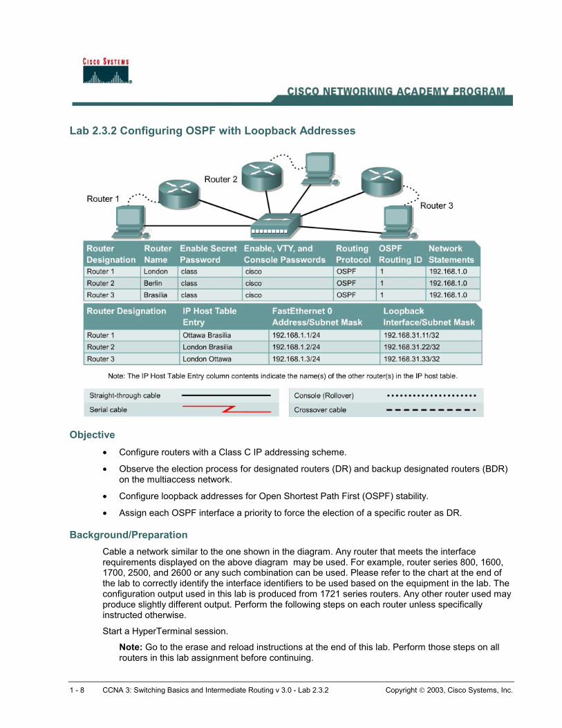
1 - 8 CCNA 3: Switching Basics and Intermediate Routing v 3.0 - Lab 2.3.2 Copyright 2003, Cisco Systems, Inc.
Lab 2.3.2 Configuring OSPF with Loopback Addresses
Objective • Configure routers with a Class C IP addressing scheme.
• Observe the election process for designated routers (DR) and backup designated routers (BDR) on the multiaccess network.
• Configure loopback addresses for Open Shortest Path First (OSPF) stability.
• Assign each OSPF interface a priority to force the election of a specific router as DR.
Background/Preparation Cable a network similar to the one shown in the diagram. Any router that meets the interface requirements displayed on the above diagram may be used. For example, router series 800, 1600, 1700, 2500, and 2600 or any such combination can be used. Please refer to the chart at the end of the lab to correctly identify the interface identifiers to be used based on the equipment in the lab. The configuration output used in this lab is produced from 1721 series routers. Any other router used may produce slightly different output. Perform the following steps on each router unless specifically instructed otherwise.
Start a HyperTerminal session.
Note: Go to the erase and reload instructions at the end of this lab. Perform those steps on all routers in this lab assignment before continuing.

2 - 8 CCNA 3: Switching Basics and Intermediate Routing v 3.0 - Lab 2.3.2 Copyright 2003, Cisco Systems, Inc.
Step 1 Configure the routers On the routers, enter the global configuration mode and configure the hostname as shown in the chart. Then configure the console, virtual terminal and enable passwords. Next configure the interfaces according and the IP hostnames. If there are any problems configuring the router basics, refer to the lab “Review of Basic Router Configuring with RIP”. Do not configure loopback interfaces and routing protocol yet.
Step 2 Save the configuration information for all the routers Why save the running configuration to the startup configuration?
__________________________________________________________________________
Step 3 Configure the hosts with the proper IP address, subnet mask and default gateway Each workstation should be able to ping all of the attached routers. That is because they are all part of the same subnetwork. Troubleshoot as necessary. Remember to assign a specific IP address and default gateway to the workstation. If running Windows 98, check by using Start > Run > winipcfg. If running Windows 2000, check by using the ipconfig command in a DOS window.
Step 4 View the routers configuration and interface information a. At the privileged EXEC mode prompt type: show running-config
b. Using the show ip interface brief command, check the status of each interface.
c. What is the state of the interfaces on each router?
London:
FastEthernet 0: ________________________________________________________
Serial 0: _____________________________________________________________
Serial 1: _____________________________________________________________
Loopback0: ___________________________________________________________
Ottawa:
FastEthernet 0: ________________________________________________________
Serial 0: _____________________________________________________________
Serial 1: _____________________________________________________________
Loopback0: ___________________________________________________________
Brasilia:
FastEthernet 0: ________________________________________________________
Serial 0: _____________________________________________________________
Serial 1: _____________________________________________________________
Loopback0: ___________________________________________________________

3 - 8 CCNA 3: Switching Basics and Intermediate Routing v 3.0 - Lab 2.3.2 Copyright 2003, Cisco Systems, Inc.
Step 5 Verify connectivity of the routers a. Ping all of the connected FastEthernet interfaces from each other.
b. Were the pings successful? __________________________________________________
c. If the pings were not successful, troubleshoot the router configuration, until the ping is successful.
Step 6 Configure OSPF routing on router London a. Configure an OSPF routing process on the router London. Use OSPF process number 1 and
ensure all networks are in area 0. London(config)#router ospf 1 London(config-router)#network 192.168.1.0 0.0.0.255 area 0 London(config-router)#end
b. Examine the London router running configuration file.
c. Did the IOS version automatically add any lines under router OSPF 1? ___________________
d. If there were no changes to the running configuration, type the following commands. London(config)#router ospf 1 London(config-router)#log-adjacency-changes London(config-router)#end
e. Show the routing table for router: London#show ip route
f. Are there any entries in the routing table? ___________________
g. Why? __________________________________________________________________
Step 7 Configure OSPF routing on router Ottawa a. Configure an OSPF routing process on the router Ottawa. Use OSPF process number 1 and
ensure all networks are in area 0. Ottawa(config)#router ospf 1 Ottawa(config-router)#network 192.168.1.0 0.0.0.255 area 0 Ottawa(config-router)#end
b. Examine the Ottawa running configuration file.
c. Did the IOS version automatically add any lines under router OSPF 1? ___________________
d. If there were no changes to the running configuration, type the following commands. Ottawa(config)#router ospf 1 Ottawa(config-router)#log-adjacency-changes Ottawa(config-router)#end
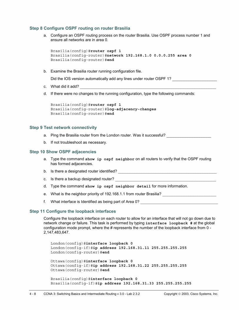
4 - 8 CCNA 3: Switching Basics and Intermediate Routing v 3.0 - Lab 2.3.2 Copyright 2003, Cisco Systems, Inc.
Step 8 Configure OSPF routing on router Brasilia a. Configure an OSPF routing process on the router Brasilia. Use OSPF process number 1 and
ensure all networks are in area 0. Brasilia(config)#router ospf 1 Brasilia(config-router)#network 192.168.1.0 0.0.0.255 area 0 Brasilia(config-router)#end
b. Examine the Brasilia router running configuration file.
Did the IOS version automatically add any lines under router OSPF 1? ___________________
c. What did it add? __________________________________________________________
d. If there were no changes to the running configuration, type the following commands: Brasilia(config)#router ospf 1 Brasilia(config-router)#log-adjacency-changes Brasilia(config-router)#end
Step 9 Test network connectivity a. Ping the Brasilia router from the London router. Was it successful? ___________________
b. If not troubleshoot as necessary.
Step 10 Show OSPF adjacencies a. Type the command show ip ospf neighbor on all routers to verify that the OSPF routing
has formed adjacencies.
b. Is there a designated router identified? __________________________________________
c. Is there a backup designated router? ___________________________________________
d. Type the command show ip ospf neighbor detail for more information.
e. What is the neighbor priority of 192.168.1.1 from router Brasilia? _______________________
f. What interface is Identified as being part of Area 0? _________________________________
Step 11 Configure the loopback interfaces Configure the loopback interface on each router to allow for an interface that will not go down due to network change or failure. This task is performed by typing interface loopback # at the global configuration mode prompt, where the # represents the number of the loopback interface from 0 - 2,147,483,647.
London(config)#interface loopback 0 London(config-if)#ip address 192.168.31.11 255.255.255.255 London(config-router)#end Ottawa(config)#interface loopback 0 Ottawa(config-if)#ip address 192.168.31.22 255.255.255.255 Ottawa(config-router)#end Brasilia(config)#interface loopback 0 Brasilia(config-if)#ip address 192.168.31.33 255.255.255.255

5 - 8 CCNA 3: Switching Basics and Intermediate Routing v 3.0 - Lab 2.3.2 Copyright 2003, Cisco Systems, Inc.
Brasilia(config-router)#end
Step 12 Save the configuration information for all the routers After saving the configurations on all of the routers, power them down and back up again.
Step 13 Show OSPF adjacencies a. Type the command show ip ospf neighbor on all routers to verify that the OSPF routing
has formed adjacencies.
b. Is there a designated router identified? __________________________________________
c. Write down the router ID and link address of the DR. _______________ ________________
d. Is there a backup designated router? ___________________________________________
e. Write down the router ID and link address of the BDR. _______________ _______________
f. What is the third router referred to as? __________________________________________
g. Write down that Routers ID and link address __________________ __________________
h. Type the command show ip ospf neighbor detail for more information.
i. What is the neighbor priority of 192.168.1.1 from router Brasilia? _______________________
j. What interface is Identified as being part of Area 0? _________________________________
Step 14. Verify OSPF interface configuration a. Type show ip ospf interface fastethernet 0 on the London router.
b. What is the OSPF state of the interface? _________________________________________
c. What is the default priority of the interface? _______________________________________
d. What is the network type of the interface? ________________________________________
Step 15 Configure London to always be the DR To ensure that London router always becomes the DR for this multi-access segment, the OSPF priority must be set. London is the most powerful router in the network and so best suited to become DR. To assign the London loopback a higher IP address is not advised, as the numbering system has advantages for troubleshooting. Also London is not to act as DR for all segments to which it may belong. Set the priority of the interface to 50 on the London router only.
Step 16 Watch election process a. To watch the OSPF election process restart all of the routers and as soon as the router prompt is
available type: Ottawa>enable Ottawa#debug ip ospf events
b. Which router was elected DR? ________________________________________________
c. Which router was elected BDR? _______________________________________________
d. Why? __________________________________________________________________
e. To turn off all debugging type undebug all.

6 - 8 CCNA 3: Switching Basics and Intermediate Routing v 3.0 - Lab 2.3.2 Copyright 2003, Cisco Systems, Inc.
Step 17 Show OSPF Adjacencies a. Type the command show ip ospf neighbor on the Ottawa router to verify that the OSPF
routing has formed adjacencies.
b. What is the priority of the DR? ________________________________________________
Once the previous steps are completed log off by typing exit, and turn the router off. Then remove and store the cables and adapter.

1 - 7 CCNA 3: Switching Basics and Intermediate Routing v 3.0 - Lab 2.3.3 Copyright 2003, Cisco Systems, Inc.
Lab 2.3.3 Modifying OSPF Cost Metric
Objective • Setup an IP addressing scheme for Open Shortest Path First (OSPF) area.
• Configure and verify OSPF routing.
• Modify OSPF cost metric on an interface.
Background/Preparation Cable a network similar to the one shown in the diagram. Any router that meets the interface requirements displayed on the above diagram may be used. For example, router series 800, 1600, 1700, 2500, and 2600 or any such combination can be used. Please refer to the chart at the end of the lab to correctly identify the interface identifiers to be used based on the equipment in the lab. The configuration output used in this lab is produced from 1721 series routers. Any other router used may produce slightly different output. Perform the following steps on each router unless specifically instructed otherwise.
Start a HyperTerminal session.
Note: Go to the erase and reload instructions at the end of this lab. Perform those steps on all routers in this lab assignment before continuing.
Step 1 Configure the routers On the routers, enter the global configuration mode and configure the hostname, console, virtual terminal, and enable passwords. Next configure the interfaces and IP hostnames according to the

2 - 7 CCNA 3: Switching Basics and Intermediate Routing v 3.0 - Lab 2.3.3 Copyright 2003, Cisco Systems, Inc.
chart. Do not configure the routing protocol until specifically told to. If there are any problems configuring the router basics, refer to the lab “Review of Basic Router Configuration with RIP”.
Step 2 Save the configuration information from the privileged EXEC command mode Cairo#copy running-config startup-config Destination filename [startup-config]?[Enter] Moscow#copy running-config startup-config Destination filename [startup-config]?[Enter]
Why save the running configuration to the startup configuration?
__________________________________________________________________________
Step 3 Configure the hosts with the proper IP address, subnet mask and default gateway a. Each workstation should be able to ping the attached router. Troubleshoot as necessary.
Remember to assign a specific IP address and default gateway to the workstation. If running Windows 9x/ME, check by using Start > Run > winipcfg. If running Windows NT/2000/XP, check by using the ipconfig command in a Command Prompt window.
b. At this point the workstations will not be able to communicate with each other. The following steps will demonstrate the process required to get communication working using OSPF as the routing protocol.
Step 4 View the routers configuration and interface information a. At the privileged EXEC mode type:
Cairo#show running-config
b. Using the show ip interface brief command, check the status of each interface.
c. What is the state of the interfaces on each router?
Cairo:
FastEthernet 0: ___________________________________________________________
Serial 0: ________________________________________________________________
Moscow:
FastEthernet 0: ___________________________________________________________
Serial 0: ________________________________________________________________
d. On a router, ping the serial interface of the other router.
e. Was the ping successful? ___________________________________________________
f. If the ping was not successful, troubleshoot the router configuration, until the ping is successful.
Step 5. Configure OSPF routing on router Cairo a. Configure OSPF routing on each router. Use OSPF process number 1 and ensure all networks
are in area 0. Cairo(config)#router ospf 1 Cairo(config-router)#network 192.168.1.128 0.0.0.63 area 0

3 - 7 CCNA 3: Switching Basics and Intermediate Routing v 3.0 - Lab 2.3.3 Copyright 2003, Cisco Systems, Inc.
Cairo(config-router)#network 192.168.1.0 0.0.0.3 area 0 Cairo(config-router)#end
b. Examine the running configuration file.
c. Did the IOS version automatically add any lines under router OSPF 1? ___________
d. What did it add? __________________________________________________________
e. If there were no changes to the running configuration, type the following commands: Cairo(config)#router ospf 1 Cairo(config-router)#log-adjacency-changes Cairo(config-router)#end
f. Show the routing table for the Cairo router. Cairo#show ip route
g. Are there any entries in the routing table? _______________
h. Why? __________________________________________________________
Step 6 Configure OSPF routing on router Moscow a. Configure OSPF routing on each router. Use OSPF process number 1 and ensure all networks
are in area 0. Moscow(config)#router ospf 1 Moscow(config-router)#network 192.168.0 .0 0.0.0.255 area 0 Moscow(config-router)#network 192.168.1.0 0.0.0.3 area 0 Moscow(config-router)#end
b. Examine the running configuration file.
c. Did the IOS version automatically add any lines under router OSPF 1? _______________
d. If there were no changes to the running configuration, type the following commands: Moscow(config)#router ospf 1 Moscow(config-router)#log-adjacency-changes Moscow(config-router)#end
Step 7 Show the routing table entries a. Show the routing table entries for the Cairo router.
Cairo#show ip route
b. Are there any OSPF entries in the routing table now? _______________________________
c. What is the metric value of the OSPF route? ______________________________________
d. What is the VIA address in the OSPF route? ______________________________________
e. Are routes to all networks shown in the routing table? _______________________________
f. What does the O mean in the first column of the routing table? _________________________

4 - 7 CCNA 3: Switching Basics and Intermediate Routing v 3.0 - Lab 2.3.3 Copyright 2003, Cisco Systems, Inc.
Step 8 Test network connectivity a. Ping the Cairo host from the Moscow host. Was it successful? _________________________
b. If not troubleshoot as necessary.
Step 9 Look at the OSPF cost on the Cairo router interfaces
a. Show the properties of the Cairo router serial and FastEthernet interfaces using the show interfaces command.
b. What is the default bandwidth of the interfaces?
c. Serial Interface: _________________________
d. FastEthernet Interface: _________________________
e. Calculate the OSPF cost.
f. Serial Interface: _________________________
g. FastEthernet Interface: _________________________
Step 10 Record the OSPF cost of the serial and FastEthernet interfaces a. Using the show ip ospf interface command, record the OSPF cost of the serial and Fast
Ethernet interfaces.
b. OSPF cost of Serial Interface: _________________________
c. OSPF cost of Ethernet Interface: _________________________
d. Do these agree with the calculations? _________________________
e. The clock rate set for the interface should have been 64000. This is what has been used as a default to this point and specified in the lab, “Review of Basic Configuration including RIP”. To calculate the cost of this actual bandwidth divide 108 by 64000.
Step 11 Manually set the cost on the serial interface On the Serial interface of the Cairo router, set the OSPF cost to 1562 by typing IP ospf cost 1562 at the serial interface configuration mode prompt.
Step 12. Verify cost a. Note that it is essential that all connected links agree about the cost for consistent calculation of
the shortest path first algorithm (SPF) in an area.
b. Verify that the interface OSPF cost was successfully modified.
Link Bandwidth Default OSPF Cost
56 Kbps 1785
T1 65
10-Mbps 10
16-Mbps Token-ring 6
FDDI/Fast Ethernet 1

5 - 7 CCNA 3: Switching Basics and Intermediate Routing v 3.0 - Lab 2.3.3 Copyright 2003, Cisco Systems, Inc.
c. Reverse the effect of this command by entering in interface configuration mode the command no ip ospf cost.
d. Verify that the default cost for the interface has returned.
e. Enter the command bandwidth 2000 at the serial 0 interface configuration mode.
f. Record the new OSPF cost of the Serial interface. _________________________
g. Can the OSPF cost of an Ethernet interface be modified in this way? ____________________
h. The speed can be set on an Ethernet interface. Will this affect the OSPF cost of that interface?
__________________________________________________________________________
i. Verify or explain the above answer.
__________________________________________________________________________
__________________________________________________________________________
__________________________________________________________________________
__________________________________________________________________________
j. Reset the bandwidth on the serial interface using the no bandwidth 2000 at the serial 0 interface configuration mode.
Once completion previous steps are completed, log off by typing exit, and turn the router off. Then remove and store the cables and adapters.

1 - 5 CCNA 3: Switching Basics and Intermediate Routing v 3.0 - Lab 2.3.4 Copyright 2003, Cisco Systems, Inc.
Lab 2.3.4 Configuring OSPF Authentication
Objective
• Setup an IP addressing scheme for Open Shortest Path First (OSPF) area.
• Configure and verify OSPF routing.
• Introduce OSPF authentication into the area.
Background/Preparation Cable a network similar to the one shown in the diagram. Any router that meets the interface requirements displayed on the above diagram may be used. For example, router series 800, 1600, 1700, 2500, and 2600 or any such combination can be used. Please refer to the chart at the end of the lab to correctly identify the interface identifiers to be used based on the equipment in lab. The configuration output used in this lab is produced from 1721 series routers. Any other router used may produce slightly different output. Perform the following steps on each router unless specifically instructed otherwise.
Start a HyperTerminal session.
Note: Go to the erase and reload instructions at the end of this lab. Perform those steps on all routers in this lab assignment before continuing.
Step 1 Configure the routers On the routers, enter the global configuration mode and configure the hostname, console, virtual terminal and enable passwords. Next configure the interfaces and IP hostnames according to the

2 - 5 CCNA 3: Switching Basics and Intermediate Routing v 3.0 - Lab 2.3.4 Copyright 2003, Cisco Systems, Inc.
chart. Do not configure the routing protocol until specifically told to. If there are any problems configuring the router basics, refer to the lab “Review of Basic Router Configuration with RIP”.
Step 2 Save the configuration information from the privileged EXEC command mode Dublin#copy running-config startup-config Destination filename [startup-config]? [Enter] Washington#copy running-config startup-config Destination filename [startup-config]? [Enter]
Why save the running configuration to the startup configuration?
__________________________________________________________________________
Step 3 Configure the hosts with the proper IP address, subnet mask and default gateway a. Each workstation should be able to ping the attached router. Troubleshoot as necessary.
Remember to assign a specific IP address and default gateway to the workstation. If running Windows 9x/ME, check by using Start > Run > winipcfg. If running Windows NT/2000/XP, check by using the ipconfig command in a Command Prompt window.
b. At this point the workstations will not be able to communicate with each other. The following steps will demonstrate the process required to get communication working using OSPF as the routing protocol.
Step 4 Verify connectivity a. On a router, ping the serial interface of the other router.
b. What the ping successful? ___________________________________________________
c. If the ping was not successful, troubleshoot the routers configurations, until the ping is successful.
Step 5 Configure OSPF routing on both routers a. Configure OSPF routing on each router. Use OSPF process number 1 and ensure all networks
are in area 0. Refer to the lab, “Configuring Loopback Interfaces” for review on configuring OSPF routing if necessary.
b. Examine the Dublin router running configuration file. Did the IOS version automatically add any lines under router OSPF 1? _____________
c. Show the routing table for the Dublin router. Dublin#show ip route
d. Are there any entries in the routing table?
e. Why? _________________________________________________________________
Step 6 Test network connectivity a. Ping the Dublin host from the Washington host. Was it successful? _____________
b. If not troubleshoot as necessary.
3 - 5 CCNA 3: Switching Basics and Intermediate Routing v 3.0 - Lab 2.3.4 Copyright 2003, Cisco Systems, Inc.
Step 7 Setup up OSPF authentication a. OSPF authentication is being established on the routers in the network. First, introduce
authentication only on the Dublin router.
b. In the interface configuration mode on Serial 0, enter the command ip ospf message-digest-key 1 md5 7 asecret.
s Dublin(config)#interface Serial 0 Dublin(config-if)#ip ospf message-digest-key 1 md5 ? <0-7> Encryption type (0 for not yet encrypted, 7 for proprietary) Dublin(config-if)#ip ospf message-digest-key 1 md5 7 ? LINE The OSPF password (key) Dublin(config-if)#ip ospf message-digest-key 1 md5 7 asecret
c. What is the OSPF password being used for md5 authentication? _______________________
d. What encryption type is being used? ____________________________________________
Step 8 Enable OSPF authentication in this area, area 0 Dublin(config-if)#router ospf 1 Dublin(config-router)#area 0 authentication
a. Wait for a few seconds. Does the router generate any output? _________________
b. Enter the command show ip ospf neighbor.
c. Are there any ospf neighbors? _________________
d. Examine the routing table by entering show ip route.
e. Are there any OSPF routes in the Dublin router routing table?
f. Can the Dublin host ping the Washington host? _________________
g. Enter these configuration commands, one per line. End with CNTL/Z. Washington#configure terminal Washington(config)#interface serial 0 Washington(config-if)#ip ospf message-digest-key 1 md5 7 asecret Washington(config-if)#router ospf 1 Washington(config-router)#area 0 authentication
h. Verify that there is an OSPF neighbor by entering show ip ospf neighbor command.
i. Show the routing table by typing show ip route.
j. Ping the Washington host from Dublin. If this was not successful troubleshoot as necessary.
Once the previous steps are completed, log off by typing exit, and turn the router off. Then remove and store the cables and adapter.

1 - 6 CCNA 3: Switching Basics and Intermediate Routing v 3.0 - Lab 2.3.5 Copyright 2003, Cisco Systems, Inc.
Lab 2.3.5 Configuring OSPF Timers
Objective
• Setup an IP addressing scheme for OSPF area.
• Configure and verify OSPF routing.
• Modify OSPF interface timers to adjust efficiency of network.
Background/Preparation Cable a network similar to the one shown in the diagram. Any router that meets the interface requirements displayed on the above diagram may be used. For example, router series 800, 1600, 1700, 2500, and 2600 or any such combination can be used. Please refer to the chart at the end of the lab to correctly identify the interface identifiers to be used based on the equipment in lab. The configuration output used in this lab is produced from 1721 series routers. Any other router used may produce slightly different output. Perform the following steps on each router unless specifically instructed otherwise.
Start a HyperTerminal session.
Note: Go to the erase and reload instructions at the end of this lab. Perform those steps on all routers in this lab assignment before continuing.
2 - 6 CCNA 3: Switching Basics and Intermediate Routing v 3.0 - Lab 2.3.5 Copyright 2003, Cisco Systems, Inc.
Step 1 Configure the routers On the routers, enter the global configuration mode and configure the hostname, console, virtual terminal and enable passwords. Next configure the interfaces and IP hostnames according to the chart. Do not configure the routing protocol until specifically told to. If there are any problems configuring the router basics, refer to the lab “Review of Basic Router Configuration with RIP”.
Step 2 Save the configuration information from the privileged EXEC command mode Sydney#copy running-config startup-config Destination filename [startup-config]? [Enter] Rome#copy running-config startup-config Destination filename [startup-config]? [Enter]
Why save the running configuration to the startup configuration?
__________________________________________________________________________
Step 3 Configure the hosts with the proper IP address, subnet mask, and default gateway a. Each workstation should be able to ping the attached router. Troubleshoot as necessary.
Remember to assign a specific IP address and default gateway to the workstation. If running Windows 9x/ME, check by using Start > Run > winipcfg. If running WindowsNT/2000/XP, check by using the ipconfig command in a DOS window.
b. At this point the workstations will not be able to communicate with each other. The following steps will demonstrate the process required to get communication working using OSPF as the routing protocol.
Step 4 Verify connectivity a. On a router, ping the serial interface of the other router.
b. What the ping successful? ___________________________________________________
c. If the ping was not successful, troubleshoot the router configurations, until the ping is successful.
Step 5 Configure OSPF routing on both routers a. Configure OSPF routing on each router. Use OSPF process number 1 and ensure all networks
are in area 0. Refer to the lab, “Configuring Loopback Interfaces” for review on configuring OSPF routing if necessary.
b. Did the IOS version automatically add any lines under router OSPF 1? ___________________
c. Show the routing table for the Sydney router. Sydney#show ip route
d. Are there any entries in the routing table? ________________________________________
Step 6 Test network connectivity Ping the Sydney host from the Rome host. Was it successful? ___________________________
If not troubleshoot as necessary.

3 - 6 CCNA 3: Switching Basics and Intermediate Routing v 3.0 - Lab 2.3.5 Copyright 2003, Cisco Systems, Inc.
Step 7 Observe OSPF traffic a. At the privileged EXEC mode type the command debug ip ospf events and observe the
output.
b. How frequently are Hello messages sent? ________________________________________
c. Where are they coming from? ________________________________________________
d. Turn off debugging by typing no debug ip ospf events or undebug all.
Step 8 Show interface timer information a. Show the hello and dead interval timers on the Sydney router Ethernet and serial interfaces by
entering the command show ip ospf interface in privileged EXEC mode.
b. Record the Hello and Dead Interval timers for these interfaces
c. Hello Interval: ____________________________________________________________
d. Dead Interval: ____________________________________________________________
e. What is the purpose of the dead interval? ________________________________________
Step 9 Modify the OSPF timers a. Modify the Hello and Dead-Interval timers to smaller values to try to improve performance. On
the Sydney router only enter the commands ip ospf hello-interval 5 and ip ospf dead-interval 20 for interface Serial 0.
Sydney(config)#interface Serial 0 Sydney(config-if)#ip ospf hello-interval 5 Sydney(config-if)#ip ospf dead-interval 20
b. Wait for a minute and then enter the command show ip ospf neighbor.
c. Are there any OSPF neighbors? ________________________________________
Step 10 Examine the routing table a. Examine the Sydney router routing table by entering show ip route.
b. Are there any OSPF routes in the table? ________________________________________
c. Can the Sydney Host ping the Rome host? _______________________________________
Step 11 Look at the OSPF data transmissions. a. Enter the command debug ip ospf events in privileged EXEC mode.
b. Is there an issue that is identified? ________________________________________
c. If there is, what is the issue? ________________________________________
Step 12 Check the Rome router routing table status. a. On the Rome router check the routing table by typing show ip route.
b. Are there any OSPF routes in the table? ________________________________________

4 - 6 CCNA 3: Switching Basics and Intermediate Routing v 3.0 - Lab 2.3.5 Copyright 2003, Cisco Systems, Inc.
Step 13 Set the Rome router interval timers a. Match the timer values on the Rome Serial link with the Sydney router.
Rome(config)#interface serial 0 Rome(config-if)#ip ospf hello-interval 5 Rome(config-if)#ip ospf dead-interval 20
b. Verify the OSPF neighbor by entering show ip ospf neighbor command.
c. Show the routing table by typing show ip route.
d. Are there OSPF routes in the table? ________________________________________
e. Ping the Rome host from Sydney. If this was not successful troubleshoot the configurations.
Step 14 Reset the routers interval timers to the default values Use the no form of the ip ospf hello-interval and the ip ospf dead-interval to reset the OSPF timers back to their default values.
Step 15 Verify the interval timers are returned to the default values a. Use the show ip ospf interface command to verify the timers are reset to their default
values.
b. Are the values back to the default? ________________________________________
c. If not, repeat step 13 and verify again.
Once the previous steps are completed, logoff by typing exit, and turn the router off. Then remove and store the cables and adapter.

1 - 6 CCNA 3: Switching Basics and Intermediate Routing v 3.0 - Lab 2.3.6 Copyright 2003, Cisco Systems, Inc.
Lab 2.3.6 Propagating Default Routes in an OSPF Domain
Objective
• Setup an IP addressing scheme for OSPF area.
• Configure and verify Open Shortest Path First (OSPF) routing.
• Configure the OSPF network so that all hosts in OSPF area can connect to outside networks.
Background/Preparation Cable a network similar to the one shown in the diagram. Any router that meets the interface requirements displayed on the above diagram may be used. For example, router series 800, 1600, 1700, 2500, and 2600 or any such combination can be used. Please refer to the chart at the end of the lab to correctly identify the interface identifiers to be used based on the equipment in the lab. The configuration output used in this lab is produced from 1721 series routers. Any other router used may produce slightly different output. Perform the following steps on each router unless specifically instructed otherwise.
Start a HyperTerminal session.
Note: Go to the erase and reload instructions at the end of this lab. Perform those steps on all routers in this lab assignment before continuing.

2 - 6 CCNA 3: Switching Basics and Intermediate Routing v 3.0 - Lab 2.3.6 Copyright 2003, Cisco Systems, Inc.
Step 1 Configure the ISP router Normally the ISP router would be configured by the Internet service provider (ISP). For the purpose of this lab, after erasing the old configuration, configure the ISP router (Router 3) this way by typing:
Router>enable Router#configure terminal Router(config)#hostname ISP ISP(config)#line vty 0 4 ISP(config-line)#password cisco ISP(config-line)#login ISP(config-line)#interface serial 1 ISP(config-if)#ip address 200.20.20.1 255.255.255.252 ISP(config-if)#clock rate 64000 ISP(config-if)#no shutdown ISP(config-if)#interface loopback 0 ISP(config-if)#ip address 138.25.6.33 255.255.255.255 ISP(config-if)#exit ISP(config)#ip route 192.168.1.0 255.255.255.0 200.20.20.2 ISP(config)#ip route 192.168.0.0 255.255.255.0 200.20.20.2 ISP(config)#end ISP#copy running-config startup-config Destination filename [startup-config]? [Enter] Building configuration... [OK] ISP#
Step 2 Configure the Area 0 OSPF routers On the routers, enter the global configuration mode and configure the hostname, console, virtual terminal and enable passwords. Next configure the interfaces and IP hostnames according to the chart. Do not configure the routing protocol until specifically told to. If there are any problems configuring the router basics, refer to the lab “Review of Basic Router Configuration with RIP”.
Step 3 Save the configuration information from the privileged EXEC command mode Tokyo#copy running-config startup-config Destination filename [startup-config]? [Enter] Madrid#copy running-config startup-config Destination filename [startup-config]? [Enter]
Why save the running configuration to the startup configuration?
__________________________________________________________________________
Step 4 Configure the hosts with the proper IP address, subnet mask and default gateway a. Each workstation should be able to ping the attached router. Troubleshoot as necessary.
Remember to assign a specific IP address and default gateway to the workstation. If running Windows 9x/ME, check by using Start > Run > winipcfg. If running Windows NT/2000/XP, check by using the ipconfig command in a DOS window.
b. At this point the workstations will not be able to communicate with each other. The following steps will demonstrate the process required to get communication working using OSPF as the routing protocol.

3 - 6 CCNA 3: Switching Basics and Intermediate Routing v 3.0 - Lab 2.3.6 Copyright 2003, Cisco Systems, Inc.
Step 5 Verify connectivity a. Ping from the Madrid router to both the Tokyo and the ISP routers.
b. Were the pings successful? __________________________________________________
c. If the ping was not successful, troubleshoot the router configurations, until the ping is successful.
Step 6 Configure OSPF routing on both area 0 routers a. Configure OSPF routing on each router. Use OSPF process number 1 and ensure all networks
are in area 0. Refer to the lab “Configuring loopback interfaces” for review on configuring OSPF routing if necessary.
b. Did the IOS version automatically add any lines under router OSPF 1? ___________________
c. Show the routing table for the Tokyo router. okyo#show ip route
d. Are there any entries in the routing table? ________________________________________
Step 7 Test network connectivity a. Ping the Tokyo host from the Madrid host. Was it successful? _________________________
b. If not troubleshoot as necessary.
Step 8 Observe OSPF traffic a. At privileged EXEC mode type the command debug ip ospf events and observe the
output.
b. Is there OSPF traffic? ____________________________
c. Turn off debugging by typing no debug ip ospf events or undebug all.
Step 9 Create a default route to the ISP On the Madrid router only, type in a static default route through Serial 1 interface.
Madrid(config)#ip route 0.0.0.0 0.0.0.0 200.200.200.1
Step 10 Verify the default static route a. Verify the default static route by looking at the Madrid routing table.
b. Is the default route in the routing table? ____________________________
Step 11 Verify connectivity from the Madrid router a. Verify connectivity from the Madrid router by pinging the ISP Serial 1 interface from the Madrid
router.
b. Can the interface be pinged? _________________________________________________
c. Next, on the host attached to Madrid, open a Command Prompt and ping the serial 1 interface on the ISP router.
d. Can the interface be pinged? _________________________________________________
e. This time, ping the loopback address of the ISP router, which represents the ISP connection to the Internet.

4 - 6 CCNA 3: Switching Basics and Intermediate Routing v 3.0 - Lab 2.3.6 Copyright 2003, Cisco Systems, Inc.
f. Can the loopback interface be pinged? __________________________________________
g. All of these pings should be successful. If they are not, troubleshoot the configurations on the host and the Madrid and ISP routers.
Step 12 Verify connectivity from the Tokyo router a. Verify the connection between the ISP and the Tokyo by pinging the serial 1 interface of the ISP
router on the Tokyo router.
b. Can the interface be pinged? _________________________________________________
c. If yes, why? If not, why not? __________________________________________________
Step 13 Redistribute the static default route a. Propagate the gateway of last resort to the other routers in the OSPF domain. At the configure
router prompt on the Madrid router type default-information originate.
Madrid(config-router)#default-information originate
b. Is there now a default route on the Tokyo router? __________________________________
c. What is the address of the Gateway of last resort? _________________________________
d. There is an O*E2 entry in the routing table. What type of route it is? _____________________
e. Can the ISP server address at 138.25.16.33 be pinged from both workstations? ____________
f. If no, troubleshoot both hosts and all three routers.
Once the previous steps are completed, log off by typing exit, and turn the router off. Then remove and store the cables and adapter.

5 - 6 CCNA 3: Switching Basics and Intermediate Routing v 3.0 - Lab 2.3.6 Copyright 2003, Cisco Systems, Inc.
Erasing and reloading the router Enter into the privileged EXEC mode by typing enable.
If prompted for a password, enter class. If that does not work, ask the instructor for assistance. Router>enable
At the privileged EXEC mode, enter the command erase startup-config.
Router#erase startup-config
The responding line prompt will be: Erasing the nvram filesystem will remove all files! Continue? [confirm]
Press Enter to confirm.
The response should be: Erase of nvram: complete
Now at the privileged EXEC mode, enter the command reload.
Router(config)#reload
The responding line prompt will be: System configuration has been modified. Save? [yes/no]:
Type n and then press Enter.
The responding line prompt will be: Proceed with reload? [confirm]
Press Enter to confirm.
In the first line of the response will be: Reload requested by console.
After the router has reloaded the line prompt will be: Would you like to enter the initial configuration dialog? [yes/no]:
Type n and then press Enter.
The responding line prompt will be: Press RETURN to get started!
Press Enter. Now the router is ready for the assigned lab to be performed.

6 - 6 CCNA 3: Switching Basics and Intermediate Routing v 3.0 - Lab 2.3.6 Copyright 2003, Cisco Systems, Inc.
Router Interface Summary
Router Model Ethernet Interface #1
Ethernet Interface #2
Serial Interface #1
Serial Interface #2
800 (806) Ethernet 0 (E0) Ethernet 1 (E1) 1600 Ethernet 0 (E0) Ethernet 1 (E1) Serial 0 (S0) Serial 1 (S1) 1700 FastEthernet 0 (FA0) FastEthernet 1 (FA1) Serial 0 (S0) Serial 1 (S1) 2500 Ethernet 0 (E0) Ethernet 1 (E1) Serial 0 (S0) Serial 1 (S1)
2600 FastEthernet 0/0 (FA0/0) FastEthernet 0/1 (FA0/1) Serial 0/0 (S0/0) Serial 0/1 (S0/1)
In order to find out exactly how the router is configured, look at the interfaces. This will identify what type and how many interfaces the router has. There is no way to effectively list all of the combinations of configurations for each router class. What is provided are the identifiers for the possible combinations of interfaces in the device. This interface chart does not include any other type of interface even though a specific router may contain one. An example of this might be an ISDN BRI interface. The string in parenthesis is the legal abbreviation that can be used in IOS command to represent the interface.