lab 6-2 configuring a wlan controller via the web...
TRANSCRIPT

1 - 16 CCNP: Building Multilayer Switched Networks v5.0 - Lab 6-2 Copyright © 2006, Cisco Systems, Inc
Lab 6-2 Configuring a WLAN Controller via the Web Interface
Topology Diagrams
Physical Diagram

2 - 16 CCNP: Building Multilayer Switched Networks v5.0 - Lab 6-2 Copyright © 2006, Cisco Systems, Inc
Logical Diagram
Scenario
Continuing from the previous lab, you will now set up the WLAN controller through its web interface. Previously you configured it through the CLI.
Step 1
Set up all the switches as they were in the previous lab. Make sure that the WLAN controller and host also have the same configuration as before.
Step 2
On the host, open up a browser and go to “https://172.16.1.100”. This is the secure method of connecting to the management interface of the WLAN controller. You can also use “http://172.16.1.100” because we previously enabled regular insecure HTTP access in Lab 6.1. If you connect to the secure address, you may be prompted with a security warning. Click Yes to accept it. You are then presented with the login screen for the WLAN controller. Click Login and an authentication dialog box appears.

3 - 16 CCNP: Building Multilayer Switched Networks v5.0 - Lab 6-2 Copyright © 2006, Cisco Systems, Inc
Authentication Dialog Box for WLAN Controller Web Access
Use “cisco” as both the username and password, which you configured in the previous lab. Click OK. The monitor page for the WLAN controller appears.

4 - 16 CCNP: Building Multilayer Switched Networks v5.0 - Lab 6-2 Copyright © 2006, Cisco Systems, Inc
WLAN Controller Monitor Page
Make sure that you see two access points under Access Point Summary. You may also see it detecting rogue access points if your lab has other wireless networks around it; this behavior is normal. You can view various port controller and port statistics by clicking their respective links in the menu on the left side of the screen.
Step 3
Add the logical interfaces on the WLAN controller that correspond to VLANs 2 and 3. First click Controller at the top of the page, and then click the Interfaces link on the left side.
5 - 16 CCNP: Building Multilayer Switched Networks v5.0 - Lab 6-2 Copyright © 2006, Cisco Systems, Inc
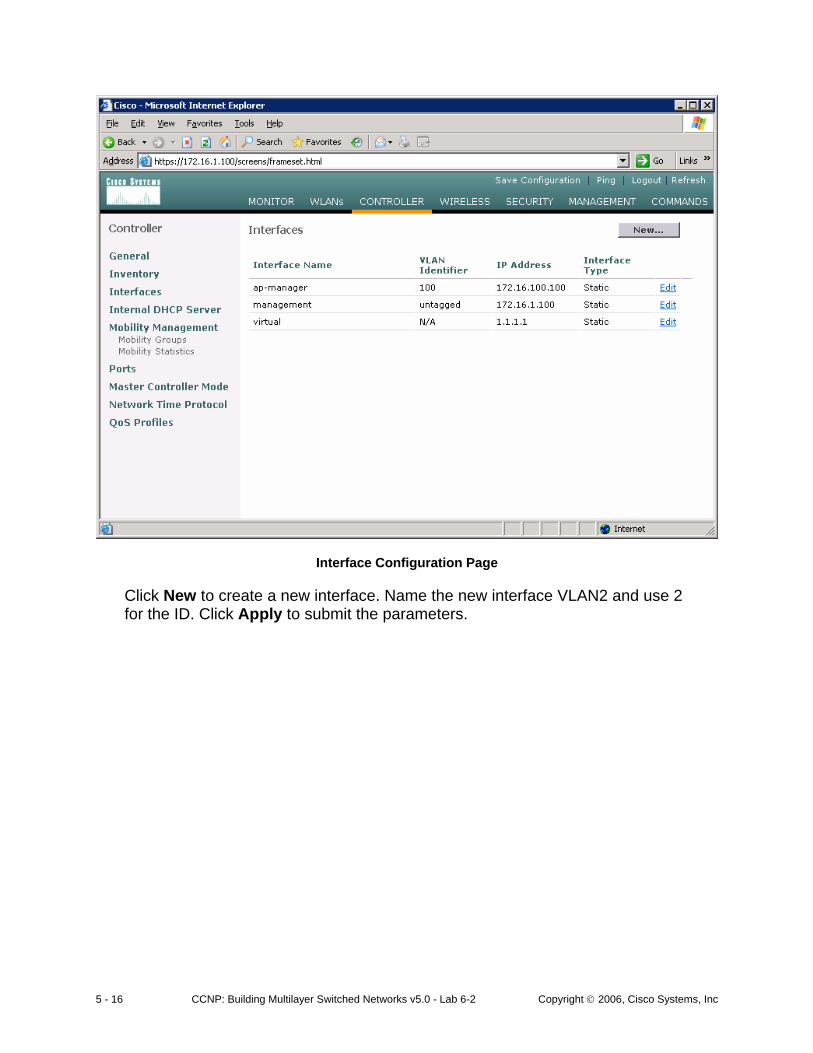
Interface Configuration Page
Click New to create a new interface. Name the new interface VLAN2 and use 2 for the ID. Click Apply to submit the parameters.

6 - 16 CCNP: Building Multilayer Switched Networks v5.0 - Lab 6-2 Copyright © 2006, Cisco Systems, Inc
Creating a New VLAN Interface
On the next page, configure the IP address shown in the diagram. Also configure this on physical port 1, because that is the port trunked to the switch. After you have made your changes, click Apply. Click OK to the warning stating that there may be a temporary connectivity loss on the APs while changes are applied.

7 - 16 CCNP: Building Multilayer Switched Networks v5.0 - Lab 6-2 Copyright © 2006, Cisco Systems, Inc
Configuring VLAN Interface Properties
The new interface should appear in the interfaces list. Repeat the configuration steps for VLAN 3.

8 - 16 CCNP: Building Multilayer Switched Networks v5.0 - Lab 6-2 Copyright © 2006, Cisco Systems, Inc
Verify Existing VLAN Interfaces

9 - 16 CCNP: Building Multilayer Switched Networks v5.0 - Lab 6-2 Copyright © 2006, Cisco Systems, Inc
Configuring the VLAN 3 Interface
Make sure both interfaces appear in the interface table.

10 - 16 CCNP: Building Multilayer Switched Networks v5.0 - Lab 6-2 Copyright © 2006, Cisco Systems, Inc
Verifying VLAN Interfaces on the WLAN Controller
Step 4
Configure the WLANs that correspond to the VLANs. Click WLANs at the top of the page to view all the configured WLANs.

11 - 16 CCNP: Building Multilayer Switched Networks v5.0 - Lab 6-2 Copyright © 2006, Cisco Systems, Inc
Viewing Existing WLANs
Click Edit to the right of the WLAN, and then remove Layer 2 security and change the interface to VLAN2. This associates the WLAN with the correct VLAN.

12 - 16 CCNP: Building Multilayer Switched Networks v5.0 - Lab 6-2 Copyright © 2006, Cisco Systems, Inc
Edit the Configuration for WLAN 1
Click Apply and then click OK to the warning box that appears.

13 - 16 CCNP: Building Multilayer Switched Networks v5.0 - Lab 6-2 Copyright © 2006, Cisco Systems, Inc
WLAN 1 Without a Security Policy
Click New to configure a WLAN for VLAN 3. Use the SSID “ccnplab.”

14 - 16 CCNP: Building Multilayer Switched Networks v5.0 - Lab 6-2 Copyright © 2006, Cisco Systems, Inc
Adding a New SSID for WLAN 2
On this WLAN, configure the Layer 2 security as Static WEP and use a 40-bit WEP key. Make the key index 2 and use a key of “cisco.” Also set the administrative status of the WLAN to enabled and change the interface name to VLAN2. When you are done, click Apply. You should see both WLANs in the WLAN list.

15 - 16 CCNP: Building Multilayer Switched Networks v5.0 - Lab 6-2 Copyright © 2006, Cisco Systems, Inc
Configuring VLAN Association and Authentication for VLAN 3
16 - 16 CCNP: Building Multilayer Switched Networks v5.0 - Lab 6-2 Copyright © 2006, Cisco Systems, Inc
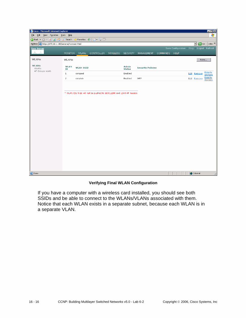
Verifying Final WLAN Configuration
If you have a computer with a wireless card installed, you should see both SSIDs and be able to connect to the WLANs/VLANs associated with them. Notice that each WLAN exists in a separate subnet, because each WLAN is in a separate VLAN.