lab-1: introduction to arduinomct.asu.edu.eg/uploads/1/4/0/8/14081679/lab1.pdf · lab(1) objective:...
TRANSCRIPT

Mechatronics Engineering and Automation
Faculty of Engineering, Ain Shams University
MCT-151, Spring 2015
Lab-1: Introduction to Arduino
Ahmed Okasha

LAB(1) Objective:
Understand what is meant by Microcontroller, Microprocessor, Embedded System, Integrated Development Environment (IDE), and Arduino.
Understand the layout of Arduino UNO board.
Understand Arduino IDE, and how to write, compile, and upload a code to Arduino.
Deal with LED using Arduino digital output pins.
Understand the difference between Pull-up and Pull-down resistors configurations.
Use push buttons
Understand switch bouncing problem and how to overcome it by simple coding solution.

What is a Microcontroller?
Basically, any product or device that
interacts with its user has a
microcontroller buried inside.

What is a Microcontroller?
A microcontroller is a computer. All computers have several things
in common:
1. All computers have a CPU (central processing unit) that executes
programs.
2. The computer has some RAM (random-access memory) where it can
store "variables."
3. And the computer has some input and output devices so it can talk to
people. On your desktop machine, the keyboard and mouse are input
devices and the monitor and printer are output devices. A hard disk is an
I/O device -- it handles both input and output.

What is a Microcontroller?
But, Microcontrollers are "special purpose computers.“ that
differs from the PC on:
1. Microcontrollers are "embedded" inside some other device
(often a consumer product) so that they can control the
features or actions of the product.
2. Microcontrollers are dedicated to one task and run one
specific program. The program is stored in ROM(read-only
memory) and generally does not change.
3. Microcontrollers are often low-power devices. A desktop
computer is almost always plugged into a wall socket and
might consume 50 watts of electricity. A battery-operated
microcontroller might consume 50 milliwatts.

www.mikroe.com/chapters/view/1
What is a Microcontroller?
A small computer on a
single chip
Containing a processor,
memory, and input/output
Typically "embedded"
inside some device that they control
A microcontroller is often small and low cost

Common Microcontroller brands
Intel
Atmel
Motorola
Microchip (PIC)
Plus many others
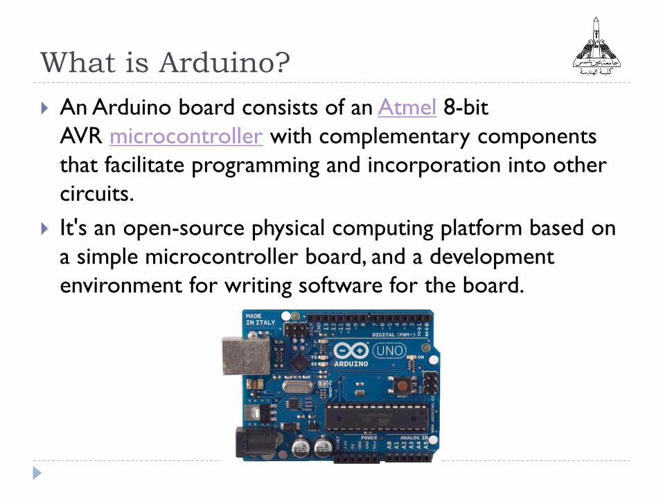
What is Arduino?
An Arduino board consists of an Atmel 8-bit
AVR microcontroller with complementary components
that facilitate programming and incorporation into other
circuits.
It's an open-source physical computing platform based on
a simple microcontroller board, and a development
environment for writing software for the board.

What is Arduino?
Photo from: http://reso-nance.org/
todbot.com/blog/bionicarduino

Why Arduino?
Open source and extensible software- The Arduino software is
published as open source tools, available for extension by
experienced programmers. The language can be expanded
through C++ libraries
Open source and extensible hardware - The Arduino is based
on Atmel's ATMEGA8 and ATMEGA168 microcontrollers. The
plans for the modules are published under a Creative
Commons license, so experienced circuit designers can make
their own version of the module, extending it and improving it.
Inexpensive
Cross-platform
Simple, clear programming environment

What is a Library?
A library is a big collection of procedures, where all the
procedures are related! If you, say, want to control a
motor, you may want to find a Motor Control Library: a
collection of procedures that have already been written
for you that you can use without having to do the dirty
work of learning the nuances of motors.

Examples of Arduino Projects

Arduino UNO board

UNO specsMicrocontroller ATmega328
Operating Voltage 5V
Input Voltage (recommended) 7-12V
Input Voltage (limits) 6-20V
Digital I/O Pins 14 (of which 6 provide PWM output)
Analog Input Pins 6
DC Current per I/O Pin 40 mA
DC Current for 3.3V Pin 50 mA
Flash Memory32 KB (ATmega328) of which 0.5 KB used
by bootloader
SRAM 2 KB (ATmega328)
EEPROM 1 KB (ATmega328)
Clock Speed 16 MHz
Length 68.6 mm
Width 53.4 mm
Weight 25 g

Memory Types

Arduino has:
Flash memory: it's a rewritable non-volatile memory. This means that its content will still be there if you turn off the power. It's a bit like the hard disk on the arduino board. Your program is stored here. code for writing and retrieving any data structure to EEPROM easily.
RAM: it's like the RAM in your computer. Its content disappears when you turn off the power, but it can be read and written really fast. Every normal variable in your sketch is held in RAM while your sketch runs.
EEPROM: it's an older technology to implement rewritable non-volatile memory. It's normally used to store settings and other parameters between resets.

Power
The Arduino Uno can be powered via the USB connection or with an external power supply. The power source is selected automatically.
External (non-USB) power can come either from an AC-to-DC adapter (wall-wart) or battery. The adapter can be connected by plugging a 2.1mm center-positive plug into the board's power jack. Leads from a battery can be inserted in the Gnd and Vin pin headers of the POWER connector.
The board can operate on an external supply of 6 to 20 volts. If supplied with less than 7V, however, the 5V pin may supply less than five volts and the board may be unstable. If using more than 12V, the voltage regulator may overheat and damage the board. The recommended range is 7 to 12 volts.

Arduino Shields
Shields are boards that can be plugged on top of the
Arduino PCB extending its capabilities. The different
shields follow the same philosophy as the original toolkit:
they are easy to mount, and cheap to produce.

Examples Arduino Shields
Arduino Wi-Fi Shield - This is the Arduino Ethernet Shield
sans wires. This shield can get your Arduino connected to
a WiFi router, so it can host webpages and scour the
Internet.
Cellular Shield w/ SM5100B - Turn your Arduino into a
cellular phone! Send SMS text messages, or hook up a
microphone and speaker and use it to replace your
iPhone.
GPS Shield - GPS isn’t as complicated as you might think.
With a GPS Shield, your Arduino will always know where
it is.

Getting Started !
Visit: http://arduino.cc/en/Main/Software
Download & install the Arduino environment (IDE) for
Windows, Mac, or Linux. (Latest version: 1.6)
Extract the ZIP file. (The extracted folder will contain both the
Arduino program itself and also the drivers that allow the
Arduino to be connected to your computer by a USB cable.
Connect the board to your computer via the UBS cable.
The power light on the LED will light up and you may get a
'Found New Hardware‘ message from Windows.
Ignore this message and cancel any attempts that Windows
makes to try and install drivers automatically for you.

Getting Started (cont.)
Open Device Manager
Under the section “Other devices” you should see an
icon for “unknown device”, write click on it and press
update driver software.
Select the option: “Browse my computer for driver
software”.
Navigate to:
arduino-1.0.2-windows\arduino1.0.2\drivers, in the
extracted folder.
You should be done by successfully installing the Arduino
driver.

Getting Started (cont.)
Launch the Arduino IDE
Select your board (Tools>>board>>UNO)
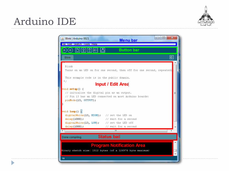
Arduino IDE

Status messages
todbot.com/blog/bionicarduino

todbot.com/blog/bionicarduino

Our First Program ! Blink
Now, you will learn how to make the built-in LED blink.

Our First Program ! Blink
You might notice that your Arduino board's built-in LED
already blinks when you connect it to a USB.
This is because Arduino boards are generally shipped with
the 'Blink' sketch preinstalled.
We will do a simple variation to the program by changing
the rate of the blink.

Our First Program ! Blink
In the IDE, select: File>>Examples>>Basics>>Blink
This is a read-only version, save it as with any other
name.

Understand the code !

Run the code
Make sure that Arduino is connected to your PC.
Click Upload and wait until the status is done.
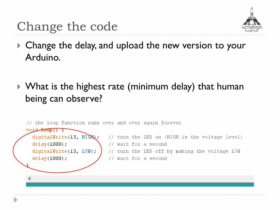
Change the code
Change the delay, and upload the new version to your
Arduino.
What is the highest rate (minimum delay) that human
being can observe?

Ex1-Blink using External LED
Connect a LED to any digital pin on your Arduino, and
put a resistance (270 ohm) in series to limit the current
passing through the LED.
Make the necessary code changes.
Change the resistance value: 470 ohm, 1K, 10K,
What is your observation?
Observation: The LED illumination decreases the as larger
resistance is used.

Ex1-Blink using External LED

Ex2-LEDs Traffic:
Design a system to demonstrate a street traffic light
system.
First state
Duration: 6 sec.
Second state
Duration: 4 sec.
Third state
Duration: 2 sec.
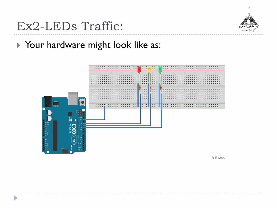
Ex2-LEDs Traffic:
Your hardware might look like as:

Digital Input
Connecting Switch to Arduino
Pull-Up Configuration

Pull-Up vs. Pull down:
Note: 5v and Gnd are taken from Arduino
http://www.devreyapimi.com/
TO
Arduino
TO
Arduino
Why the need for Pull-up and
Pull-down?
Pull-up and Pull-down resistors are used in electronic
logic circuits to ensure that inputs to the Arduino settle
at expected logic levels if external devices are
disconnected or high-impedance.
When you have nothing at all connected to an input pin
doesn't mean it is a logical zero.

Ex3-Control Led with push button
Design a system that let the user when PRESS and HOLD
a button, a LED illuminate, and when the button released,
the LED switch off. (The default of the LED status is off).

Ex4-Change LED status with push
button press
Modify the previous program to let user change the
status of the LED when the button is pressed once. (i.e:
when the LED is ON, it should go off when button is
pressed)
What is the problem you have observed?

Switch Bouncing
When a mechanical contact, such as pushbutton, switch, user-interface button, limit switch, relay, or contactor contact, is opened or closed, the contact seldom demonstrates a clean transition from one state to another. When a contact is closed or opened, it will close and open (technically speaking "make" and "break"), many times before finally settling in a stable state.
http://www.edn.com/

Software de-bouncing solution
if (reading == LOW) { //Pull up configuration
delay(200); // 200 ms delay, increase if the output flickrs
if (reading == LOW)
{
YOUR CODE
}
}

Helpful Tools
http://fritzing.org/home/
Creates virtual circuits (Schematic for your real circuits)
Has a PCB view to put components on a PCB with autoroute
feature.
Share your design (if you want)
Contain a collection of projects for beginners and advanced
users


Home Work !
Review Arduino Language:
http://arduino.cc/en/Reference/HomePage
Read the PDF of reviewing the most important functions
and instructions.

References
http://arduino.cc/
http://www.ladyada.net/learn/arduino/index.html
https://learn.adafruit.com/