la112a plansspragueaudioworks.com/sample_plans/la112a_sample_plans.pdfnote: •these plans are...
TRANSCRIPT

LA112a Plans www.spragueaudioworks.com [email protected]
These plans contain material protected under International and Federal Copyright Laws and Treaties. Any unauthorized reprint or use of this material is prohibited. Criminal copyright infringement, including infringement without monetary gain, is investigated by the FBI and is punishable by up to five years in federal prison and a fine of $250,000.
05/02/2015 1 V3.0

Note:
• These plans are incomplete and meant to show a sample of what you will build with the full set of LA112 plans – which include plans for:
– Single 12” cabinet
– Dual 12” cabinet
– Both with either a single or dual 1” waveguide.
05/02/2015 V3.0 2

Tools required
• Table Saw
• Router
• Hand held jig saw
• Drill
• Sander – bench belt sander handy for the horns
• Assorted clamps
• Optional: Air nailer
3

Speaker Part
• Woofer – Eminence Deltalite II 2512 8 ohm – Eminence KappaLite 3012 HO 8 ohm – Eminence Delta Pro-12a 8 ohm
• Compression Driver – Single driver horn: Eminence PSD 2002 or PSD 2013 8 ohm bolt-on – Dual driver horn: Eminence NSD2005 or Selenium D220 (note, the
dual driver requires a horn that is no larger than 4.5” in diameter)
• Crossover – Eminence PXB21k6 2 way 1.6K
• Misc – Grill, speakon connectors, wiring, feet, metal rigging hardware.
4
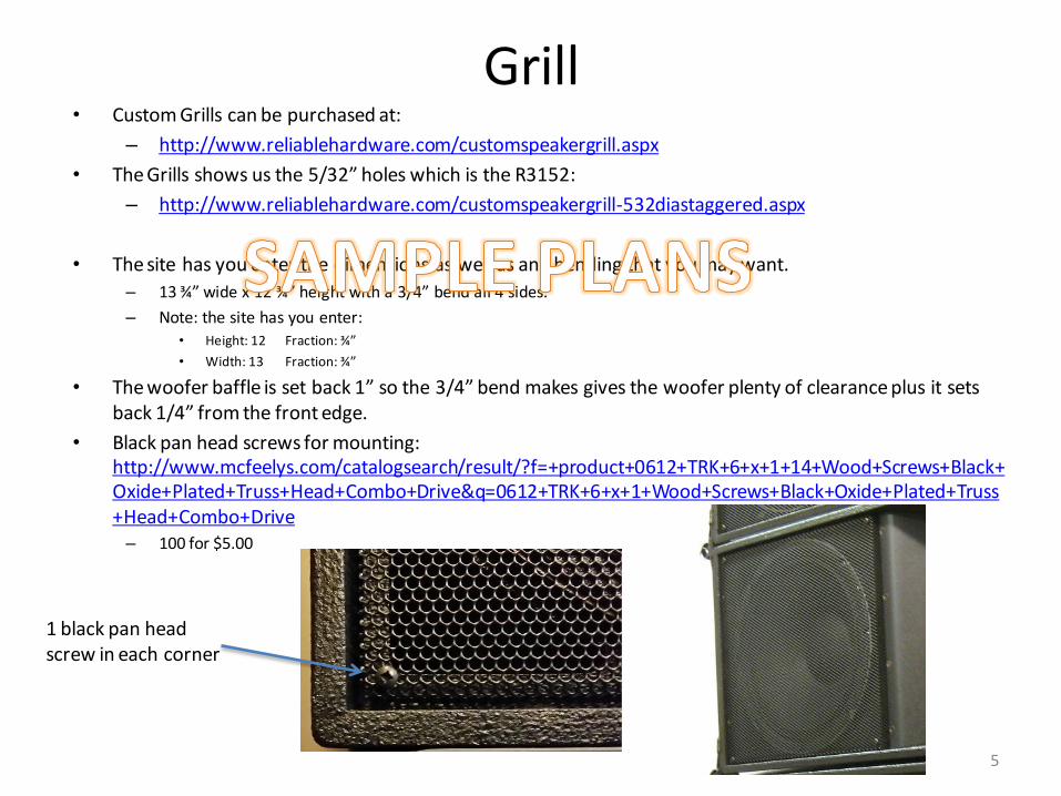
Grill • Custom Grills can be purchased at:
– http://www.reliablehardware.com/customspeakergrill.aspx
• The Grills shows us the 5/32” holes which is the R3152:
– http://www.reliablehardware.com/customspeakergrill-532diastaggered.aspx
• The site has you enter the dimensions as well as any bending that you may want.
– 13 ¾” wide x 12 ¾” height with a 3/4” bend all 4 sides.
– Note: the site has you enter: • Height: 12 Fraction: ¾”
• Width: 13 Fraction: ¾”
• The woofer baffle is set back 1” so the 3/4” bend makes gives the woofer plenty of clearance plus it sets back 1/4” from the front edge.
• Black pan head screws for mounting: http://www.mcfeelys.com/catalogsearch/result/?f=+product+0612+TRK+6+x+1+14+Wood+Screws+Black+Oxide+Plated+Truss+Head+Combo+Drive&q=0612+TRK+6+x+1+Wood+Screws+Black+Oxide+Plated+Truss+Head+Combo+Drive – 100 for $5.00
5
1 black pan head screw in each corner

Options • Horn options ( same cabinet works
for both horn options) – Single 1” compression driver horn
• Accepts very large 1” compression drivers
• Up to 7” in diameter
– Dual 1” compression driver horn • Required 2 (two) 1” compression
drivers
• Must not be larger than 4.6” in diameter
• Woofer baffle plate – Original
– New Simplified • No sonic difference – just easier to
cut
• Dual 12” woofer section – See optional section at the
end
6
brand model diameter depth weight RMS LF Freq
B&C DE400TN 3.3 1.7 1.8 50 1500
Eminence NSD2005 3.9 1.75 2.5 50 1500
RCF N350 4 2.4 3.1 40 1700
FaitalPro HF10RT 4.02 2.13 3.09 60 1300
PRV D280TiB 4.52 2 3.65 80 2000
Selenium D220Ti 4.53 2 4 80 1500
Acceptable 1” drivers for the dual horn option

Assembly Instructions Main Cabinet
• Material: – ½” high quality, void free plywood for the cabinet
• Baltic Birch plywood recommended but will result in each cabinet weighing about 4 lbs more than most other plywood
– ¼” Baltic Birch Plywood • Very small quantity used for the horn mount flanges
– ¾” Baltic Birch Plywood for the speaker baffle plate. • This is critical to be of high quality wood as the woofer
will be screwed into this plate
7
Main Cabinet
• Cut two end panels
– Cut out the handles in the end panels
– Optional: This is the time to router out a logo and round over half of the inner handle cutouts
• Cut the top and bottom panels
– Pay attention to the 7.4 degree angle on the end of each panel
• Cut out the back panel
8
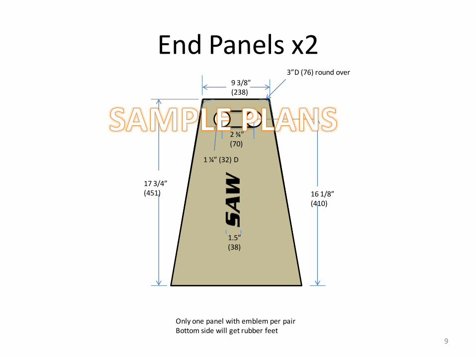
End Panels x2
17 3/4” (451) 16 1/8”
(410)
1.5” (38)
1 ¼” (32) D
Only one panel with emblem per pair Bottom side will get rubber feet
2 ¾” (70)
3”D (76) round over
9 3/8” (238)
9

Good side Short side
15/16” (24) holes drilled in the center of the outer, larger 1 ½” (38) holes for the recessed speakon connectors
Back panel – Speakon recessed panel mount
10
½” Baltic Birch backing plate glued to the inside
¼” round over with router of the outer hole before gluing the backing plate
Go
od
sid
e (o
uts
ide
of
bo
x)
insi
de
of
bo
x
NOTE: The Speakon connector panel can be modified as needed. For instance, commercial connector panels can be used here and the placement can be modified. However, ensure that they will not interfere with the divider panel. Also ensure there will be room for the crossover and clearance for the compression driver.
14.5” (368)
Divider panel only shown for Speakon connector holes if you decide for a different arrangement – see note below
Top and bottom shown for reference only

Box construction photos
Note the 7.4o panel cuts And alignment here
Ensure everything is 100% Square or the inner baffle And horn assembly will Not fit correctly and Alignment with the hanging Hardware will be off.
If unsure at this stage – build One out of scrap plywood As a throw away box to make Ensure all angles and cuts Are correct.
Use straight – void free plywood. Shown is Baltic Birch plywood. Glue used is regular wood glue (Titebond II). Air nailer used to hold joints. Must be air tight!
Small plate will be used With exact hole for Speakon Connectors (last page)
11

Note handle cutout Alignment with Back panel
Optional: before assembly, Router this part of the Handle with 3/16” round over. You will not be able to get A router in there at this point And will have to sand it
Front corner view: Note the alignment Of the top/bottom With the end panel
12

Inner box construction
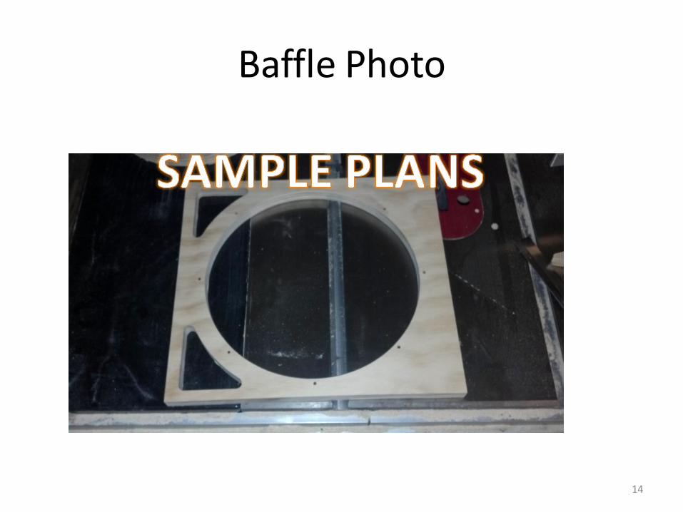
• Cut out and install the front baffle plate
– This can be trimmed to fit if the main box was not built to exact specified dimensions and not completely square
– Cut out and install the inner divider panel (Shown earlier) and a corresponding horn mounting strip
13
Baffle Photo
14

Inner box construction photos
Baffle Set back 1” (25) from front
Baffle Set back 1” (25) from front
Baffle Set back 1” (25) from front
Note: distance from front of baffle to the back should be 14” (356 mm). This will match the inner divider panel as well as The horn mounting strip coming up next
14” (356) front of baffle to back
15

Divider Panel photos
This forms the horn mounting surface and must be 14” (356) from the back with both sides parallel with each other or the horn will not fit correctly and will be under stress when mounted
16

Rigging Pin Relief Pocket
Cabinet Front
5/8” (15.9)
½” round router bit to make a relief pocket 3/16” (4.7mm)deep – NOTE: Jig used to accurately route Holes There will be 4 of these each side top and bottom. See Next slides for other views
1” (25.4)
17

4 Pin relief Pockets
Corners radius with ¼” router bit Inner and outer handles use 3/16” router bit due to ¼” guide bearing being slightly to deep. Back and front just sand
18

Purpose of this relief pocket is to allow the cabinets to fit together closer And give clearance for the rigging pin
19

20

Use panel trim bit to make the sides perfectly flush.
¼” radius on sides
21

Inner block of ½” plywood drilled exact diameter of Speakon connectors And glued on the inside. It just needs to cover the larger holes
22

23

Single 1” horn option
• This is the original wave guide horn • Allows for very large 1” compression drivers
– Should use a high quality driver with a cross over at least 1600 Hz or lower
– Skip to the section on Dual 1” horn option if you choose to build that version • However, there are good construction photos and tips that are still
applicable for both horns in this section
– Note: both horns use the same mounting and are completely
interchangeable in the cabinet • This allows for experimentation before committing to either option
when building a large number of cabinets
4/27/2014 V1.3 24

Horn panel jig
25

Horn Construction Photos
A
26
A
Make sure both horn Panels are perfectly aligned NOTE: this is shown without the Waveguide baffles – put those in Before gluing on the second panel
Make sure horn panels Are flush with panel
A

Horn Glue up
27
Note: The 1” side plates and the baffles must all be flush before the other side is glued on. Also note the small radius on the side corners of each baffle – Not the front or back – just the sides of the baffle parts
Note that these baffle blocks are the same size as for the dual CD horn

Compression Driver Flange Trimming
28

Horn Flange Parts and Assembly
Cutting jig for the 45o and 45o angles On the flanges
Glue up Jig – panels Are held 7 3/8” (187.3) apart. Final width with the Mount flanges will be 9” (228.6)
29
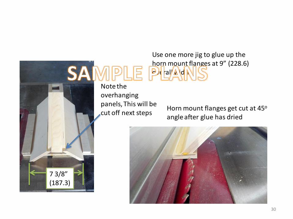
7 3/8” (187.3)
Note the overhanging panels, This will be cut off next steps
Use one more jig to glue up the horn mount flanges at 9” (228.6) overall width
Horn mount flanges get cut at 45o angle after glue has dried
30

Cutting Horn
The horn will be cut to 12 ¾” (323.8) overall length. Find the center and measure 6 3/8” (161.9) one way and cut. Then measure for the overall 12 ¾” (323.8)
for the second cut. A 10” table saw will not cut the entire depth so finish with a hand saw. Note the 7.4o angle to fit the 7.4o angle of the box. Also, some sanding on a belt sander might be
required - do several fit checks.
You should end up with a cut off piece that looks like this and is why you want the parts to be a little long when you first cut them out and glue them up
Note: this entire horn assembly can be purchased: www.spragueaudioworks.com
31

Raw Horn before drilling mount holes
32
Note the use of two ½” blocks of MFD to make up the 1” waveguide baffles.
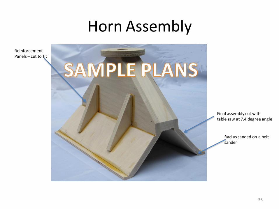
Horn Assembly Reinforcement Panels – cut to fit
Final assembly cut with table saw at 7.4 degree angle
Radius sanded on a belt sander
33

Horn Assembly Note: this entire horn assembly can be purchased: www.spragueaudioworks.com Belt sanded radius
Counter sunk holes For 1” drywall screws
34
Horn Shown without The waveguide baffles

Original Dual Horn construction photos
35
Note the reinforcement blocks – put them so they do not interfere with the driver hold-down bolts. 2” (50.8) from each end is good. See next page for a simple way to make the reinforcement blocks
Clearance slots for the rigging bolts – same as the single driver horn

NEW -- Dual 1” LA112 horn
• This new waveguide horn is an exact replacement for the original LA112 horn.
• HOWEVER – • It requires that drivers are no greater than 4.5” in
diameter – Even at that diameter, a small pocket may need to be
routed out on the inside of the box – I used two Selenium D220 Ti that are the largest in the
chart and I needed to route a 1/8” deep pocket where the drivers hit the inside of the box.
– This can be done with a small, hand held router
36

Compression Driver Options • Horn options ( same cabinet works
for both horn options)
– Dual 1” compression driver horn
• Required 2 (two) 1” compression drivers
• Must not be larger than 4.5” in diameter
37
brand model diameter depth weight RMS LF Freq
B&C DE400TN 3.3 1.7 1.8 50 1500
Eminence NSD2005 3.9 1.75 2.5 50 1500
RCF N350 4 2.4 3.1 40 1700
FaitalPro HF10RT 4.02 2.13 3.09 60 1300
PRV D280TiB 4.52 2 3.65 80 2000
Selenium D220Ti 4.53 2 4 80 1500
Acceptable 1” drivers for the dual horn option
1/8” routed pockets where the 4.5” Selenium D220 TI drivers hit

38
Ensure the glued up blocks that will make the channel dividers are the same thickness as the side wall panels Print out and tape the
paper templates to transfer onto a wood template panel
Use the wood templates to cut out the wave guide channel divider parts

Fit Check
39
The waveguide horn should set back about 1 ½” to 2” – Ideally 1 ¾” . If it sets out too close to the front, the horn flair will stick out too far and the there will be a gap where the assembly is screwed onto the cabinet
Horn Flange Mount Glue-Up
40
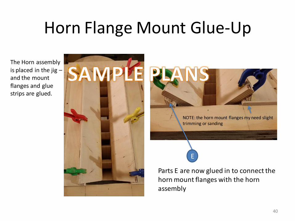
The Horn assembly is placed in the jig – and the mount flanges and glue strips are glued.
E
Parts E are now glued in to connect the horn mount flanges with the horn assembly
NOTE: the horn mount flanges my need slight trimming or sanding

Finished Horn Photos
41
Add the additional reinforcement blocks as shown

Finishing options
• Duratex – http://store.acrytech.com/Speaker-Cabinet-Coatings/
– good finish that is very safe and easy to apply. Can be applied with a roller with very professional looking results
• Polyurethane spray-on truck bed liner (this is what we use on the factory cabinets and what is shown in the photos of the finished cabinets)
• For the Horn, a can of spray-on truck bed line provides a very nice looking finish and is what is shown in the finished horn photos
42

43
+1
-1
Crossover
Parallel wiring of the Dual Speakons
+1
-1
Crossover
From Amp or other LA112 Cabinet
To next LA112 cabinet if there is one to connect –
otherwise no connection
Speaker Cabinet
Speaker Cabinet
LA112 Cabinet
LA112 Cabinet
LA112 Cabinet
LA112 Cabinet
Amp 8 Ohms
4 Ohms
2.6 Ohms
2 Ohms
Safe more most amps
Only for amps rated at 2 Ohms

Single 4 conductor stage cable
44
MainAmp
Sub Amp
+
+
-
-
4 Pole Speakon Junction panel
+1 -1
+2
-2
Long Speaker Cable
Main Speakers
Junction box
+1
-1 +1
-1
Sub
+1
-1
-1 +1
Short 2-wire Speaker Cable

½” strip 1 ½” (38.1) to mount Horn - level with baffle And divider panel
Place crossover in back to allow for Compression driver clearance
Screw pilot holes drilled in both the Horn and the cab at same time to ensure
alignment – 1” black dry wall screws
#10 x 1 ½” pan head screws
2 air tight holes for The woofer wires
45

Optional rubber feet mounted on woofer side (opposite side of the logo)
Shown with T-stand mount
46

Final photos
47

Shown with T-stand mount 48

F3: 75 HZ Box Volume: 1.02 Cu Ft Vent Area: 4.5 Sq in Vent Length: 0.75 in
Graph for Woofer section only with DeltaLite II 2512
49
With DeltaLite II 2512

F3: 79 HZ Box Volume: 1.02 Cu Ft Vent Area: 4.5 Sq in Vent Length: 0.75 in
Graph for Woofer section only with Delta Pro-12a
50
With Delta Pro-12a
Ideas for mounting
• As shown in the pictures, optional rigging plans are available for hanging or stacking the cabinets – but here are a couple of ideas that have been used and include:
– Hanging from rear eye bolts
– Fixed mounting by bolting the cabinets to a metal or wooden frame
51
None of these mounting options have been tested but are here to give you other ideas for mounting
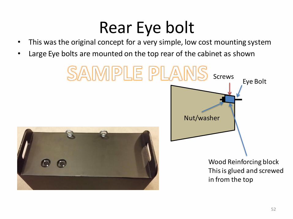
Rear Eye bolt • This was the original concept for a very simple, low cost mounting system
• Large Eye bolts are mounted on the top rear of the cabinet as shown
52
Eye Bolt
Wood Reinforcing block This is glued and screwed in from the top
Nut/washer
Screws
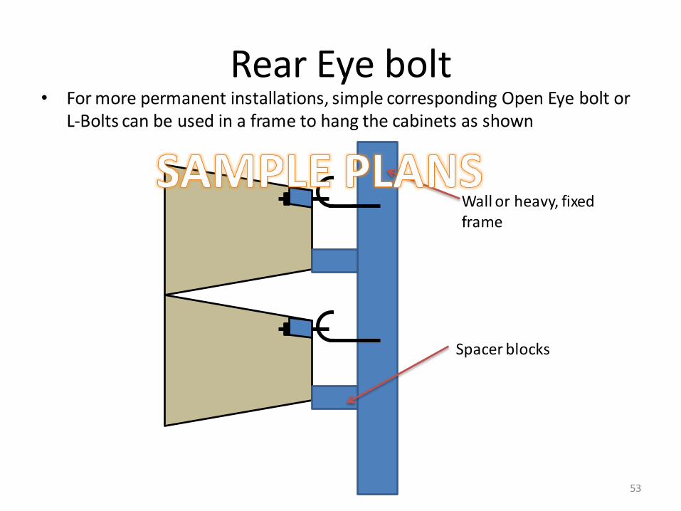
Rear Eye bolt • For more permanent installations, simple corresponding Open Eye bolt or
L-Bolts can be used in a frame to hang the cabinets as shown
53
Spacer blocks
Wall or heavy, fixed frame

Rear Eye bolt • Here are some pictures of a T-Hat mounting frame that was built to use
the Eye bolt mounts.
54
Note: This was difficult to get the boxes to align as the eye bolts did not hold the cabinets in perfect position. However, cabinets were easy to mount by simply setting a cabinet up and hanging on the eye bolts – starting from the bottom. Adjustable cabinet spacers were not very effective as the cabinets were very limited in the position that they could be mounted using this frame.

55
Rear Eye bolt
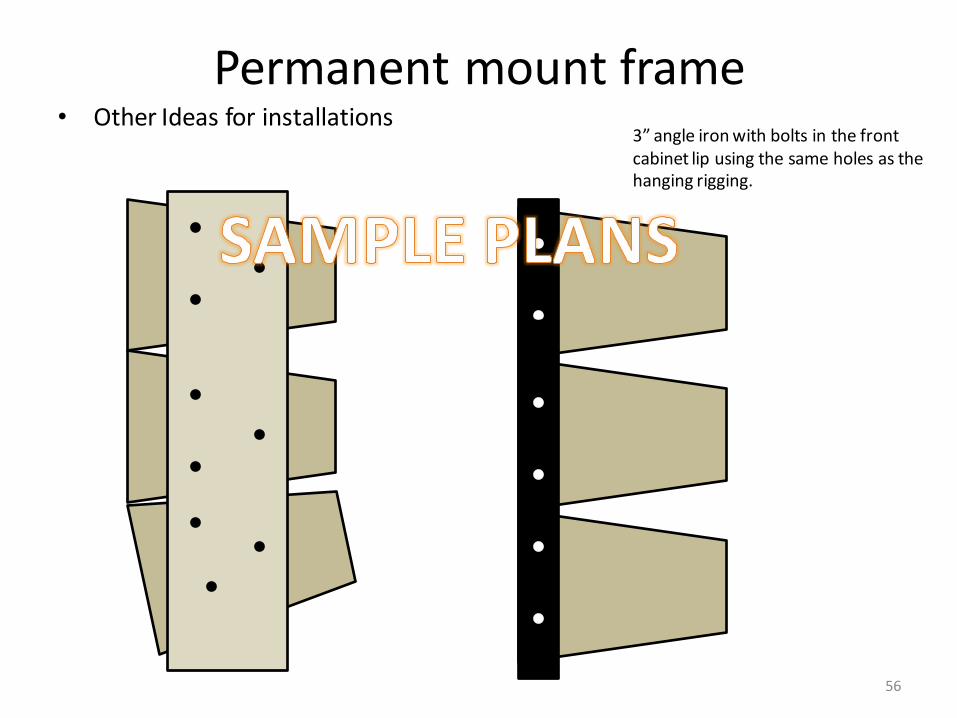
Permanent mount frame • Other Ideas for installations
56
3” angle iron with bolts in the front cabinet lip using the same holes as the hanging rigging.

Dual 12”
05/02/2015 V3.0 57
Original LA112 Added 12” Woof section
