la 822 glue guns - nordsonemanuals.nordson.com/adhesives/english_manuals/1044072.pdfla 822 glue guns...
TRANSCRIPT

LA 822 Glue Guns
Customer Product ManualPart 1044072A
Issued 7/03
NORDSON CORPORATION • DULUTH, GEORGIA • USAwww.nordson.com

Part 1044072A � 2003 Nordson CorporationAll rights reserved
Manual 52-LA822-MA-01
Nordson Corporation welcomes requests for information, comments, and inquiries about its products. General informationabout Nordson can be found on the Internet using the following address: http://www.nordson.com.
Address all correspondence to:
Nordson CorporationAttn: Customer Service11475 Lakefield Drive
Duluth, GA 30097
Notice
This is a Nordson Corporation publication which is protected by copyright. Original copyright date 2003.No part of this document may be photocopied, reproduced, or translated to another language without the prior written
consent of Nordson Corporation. The information contained in this publication is subject to change without notice.
Trademarks
AccuJet, AeroCharge, AquaGuard, Asymtek, Automove, Autotech, Baitgun, Blue Box, CanWorks, Century, CF, Clean Coat, CleanSleeve, CleanSpray,Control Coat, Coolwave, Cross-Cut, Cyclo-Kinetic, Dispensejet, DispenseMate, Durafiber, Durasystem, Easy Coat, Easymove Plus, Econo-Coat, EFD, ETI,Excel 2000, FlexiCoat, Flexi-Spray, Flex-O-Coat, Flow Sentry, Fluidmove, FoamMelt, FoamMix, Heli-flow, Helix, Horizon, Hot Shot, Isocoil, Isocore, Iso-Flo,JR, KB30, Kinetix, Little Squirt, Magnastatic, MEG, Meltex, Microcoat, Micromark, MicroSet, Millennium, Mini Squirt, Moist-Cure, Mountaingate, MultiScan,
Nordson, OmniScan, OptiMix, Package of Values, Patternview, Plasmod, PluraFoam, Porous Coat, PowderGrid, Powderware, Prism, Pro-Flo, ProLink,Pro-Meter, Pro-Stream, PRX, RBX, Rhino, Saturn, SC5, S. design stylized, Seal Sentry, Select Charge, Select Coat, Select Cure, Slautterback, Smart-Coat,
Solder Plus, Spectrum, Spraymelt, Spray Squirt, Super Squirt, Sure Coat, Tela-Therm, Tracking Plus, Trends, Tribomatic, UniScan, UpTime, Veritec,Versa-Coat, Versa-Screen, Versa-Spray, Walcom, Watermark, and When you expect more.
are registered trademarks of Nordson Corporation.
AeroDeck, AeroWash, Apogee, ATS, Auto-Flo, AutoScan, BetterBook, CanNeck, Chameleon, Check Mate, ColorMax, Controlled Fiberization,Control Weave, CoolWave, CPX, Dry Cure, DuraBlue, Dura-Coat, Dura-Screen, Easy Clean, Eclipse, EcoDry, E-Nordson, Equi=Bead, ESP, Fillmaster,Fill Sentry, Gluie, iControl, iFlow, Ink-Dot, iON, Iso-Flex, iTrend, KVLP, Lacquer Cure, March, Maxima, MicroFin, MicroMax, Minimeter, Multifil, Origin,
PermaFlo, PluraMix, Powder Pilot, Powercure, Primarc, ProBlue, Process Sentry, Pulse Spray, PurTech, Ready Coat, Scoreguard, Select Series,Sensomatic, Shaftshield, SheetAire, Spectral, Spectronic, Speed-Coat, Speedking, Spray Works, Summit, SureBead, Sure Brand, Sure Clean, Sure-Max,
Swirl Coat, Tempus, ThruWave, Trade Plus, Universal, VersaBlue, Vista, Web Cure, and 2 Rings (Design)are trademarks of Nordson Corporation.
Designations and trademarks stated in this document may be brands that, when used by third parties for their own purposes, could lead to violation of the owners’ rights.
Loctite is a registered trademark of Loctite Corporation.

Table of Contents i
Part 1044072A� 2003 Nordson Corporation Manual 52-LA822-MA-01
Table of Contents
Safety 1. . . . . . . . . . . . . . . . . . . . . . . . . . . . . . . . . . . . . . . . . . . . . . . . . . . . . . . . . Safety Alert Symbols 1. . . . . . . . . . . . . . . . . . . . . . . . . . . . . . . . . . . . . . . . . . . . Responsibilities of the Equipment Owner 2. . . . . . . . . . . . . . . . . . . . . . . . . . .
Safety Information 2. . . . . . . . . . . . . . . . . . . . . . . . . . . . . . . . . . . . . . . . . . . . Instructions, Requirements, and Standards 2. . . . . . . . . . . . . . . . . . . . . . User Qualifications 3. . . . . . . . . . . . . . . . . . . . . . . . . . . . . . . . . . . . . . . . . . .
Applicable Industry Safety Practices 3. . . . . . . . . . . . . . . . . . . . . . . . . . . . . . . Intended Use of the Equipment 3. . . . . . . . . . . . . . . . . . . . . . . . . . . . . . . . . Instructions and Safety Messages 3. . . . . . . . . . . . . . . . . . . . . . . . . . . . . . Installation Practices 4. . . . . . . . . . . . . . . . . . . . . . . . . . . . . . . . . . . . . . . . . . Operating Practices 4. . . . . . . . . . . . . . . . . . . . . . . . . . . . . . . . . . . . . . . . . . . Maintenance and Repair Practices 5. . . . . . . . . . . . . . . . . . . . . . . . . . . . . .
Equipment Safety Information 5. . . . . . . . . . . . . . . . . . . . . . . . . . . . . . . . . . . . Equipment Shutdown 5. . . . . . . . . . . . . . . . . . . . . . . . . . . . . . . . . . . . . . . . . General Safety Warnings and Cautions 6. . . . . . . . . . . . . . . . . . . . . . . . . . Other Safety Precautions 9. . . . . . . . . . . . . . . . . . . . . . . . . . . . . . . . . . . . . . First Aid 9. . . . . . . . . . . . . . . . . . . . . . . . . . . . . . . . . . . . . . . . . . . . . . . . . . . . .
Overview 10. . . . . . . . . . . . . . . . . . . . . . . . . . . . . . . . . . . . . . . . . . . . . . . . . . . . . . Installation and Electrical Connections 10. . . . . . . . . . . . . . . . . . . . . . . . . . . . . Operation 11. . . . . . . . . . . . . . . . . . . . . . . . . . . . . . . . . . . . . . . . . . . . . . . . . . . . . .
Less Obvious Dangers 12. . . . . . . . . . . . . . . . . . . . . . . . . . . . . . . . . . . . . . . . Action in the Event of System Malfunction 12. . . . . . . . . . . . . . . . . . . . . . .
Maintenance/Repair 12. . . . . . . . . . . . . . . . . . . . . . . . . . . . . . . . . . . . . . . . . . . . . Relieving Hydraulic Pressure 13. . . . . . . . . . . . . . . . . . . . . . . . . . . . . . . . . . . Before You Begin 13. . . . . . . . . . . . . . . . . . . . . . . . . . . . . . . . . . . . . . . . . . . . . Cleaning 14. . . . . . . . . . . . . . . . . . . . . . . . . . . . . . . . . . . . . . . . . . . . . . . . . . . .
Liquid Adhesives 15. . . . . . . . . . . . . . . . . . . . . . . . . . . . . . . . . . . . . . . . . . . . . . . .
Description 16. . . . . . . . . . . . . . . . . . . . . . . . . . . . . . . . . . . . . . . . . . . . . . . . . . . . Glue and Solvent Applications 16. . . . . . . . . . . . . . . . . . . . . . . . . . . . . . . . . . . .
Water-Based Glues 16. . . . . . . . . . . . . . . . . . . . . . . . . . . . . . . . . . . . . . . . . . . Solvents 16. . . . . . . . . . . . . . . . . . . . . . . . . . . . . . . . . . . . . . . . . . . . . . . . . . . . .
Standard Features 16. . . . . . . . . . . . . . . . . . . . . . . . . . . . . . . . . . . . . . . . . . . . . . LA 822M and LA 822MEK Guns 16. . . . . . . . . . . . . . . . . . . . . . . . . . . . . . . . LA 822MB Gun 17. . . . . . . . . . . . . . . . . . . . . . . . . . . . . . . . . . . . . . . . . . . . . . .
Dimensions 17. . . . . . . . . . . . . . . . . . . . . . . . . . . . . . . . . . . . . . . . . . . . . . . . . . . .
Setup 18. . . . . . . . . . . . . . . . . . . . . . . . . . . . . . . . . . . . . . . . . . . . . . . . . . . . . . . . .

Table of Contentsii
Part 1044072A � 2003 Nordson CorporationManual 52-LA822-MA-01
Operation 19. . . . . . . . . . . . . . . . . . . . . . . . . . . . . . . . . . . . . . . . . . . . . . . . . . . . . Startup 19. . . . . . . . . . . . . . . . . . . . . . . . . . . . . . . . . . . . . . . . . . . . . . . . . . . . . . . .
For Carton Folder/Gluers 20. . . . . . . . . . . . . . . . . . . . . . . . . . . . . . . . . . . . . . For Folding or Mailing Machines 20. . . . . . . . . . . . . . . . . . . . . . . . . . . . . . . .
Shutdown 21. . . . . . . . . . . . . . . . . . . . . . . . . . . . . . . . . . . . . . . . . . . . . . . . . . . . . .
Maintenance 21. . . . . . . . . . . . . . . . . . . . . . . . . . . . . . . . . . . . . . . . . . . . . . . . . . . General Cleaning 21. . . . . . . . . . . . . . . . . . . . . . . . . . . . . . . . . . . . . . . . . . . . . . .
Required Tools 21. . . . . . . . . . . . . . . . . . . . . . . . . . . . . . . . . . . . . . . . . . . . . . . Disassembly 22. . . . . . . . . . . . . . . . . . . . . . . . . . . . . . . . . . . . . . . . . . . . . . . . . Assembly 22. . . . . . . . . . . . . . . . . . . . . . . . . . . . . . . . . . . . . . . . . . . . . . . . . . . .
Cleaning Systems with Pump 23. . . . . . . . . . . . . . . . . . . . . . . . . . . . . . . . . . . . . Cleaning System with Pressure Tank 24. . . . . . . . . . . . . . . . . . . . . . . . . . . . . . Changeover from LA 822M to LA 822MB 26. . . . . . . . . . . . . . . . . . . . . . . . . .
Parts 27. . . . . . . . . . . . . . . . . . . . . . . . . . . . . . . . . . . . . . . . . . . . . . . . . . . . . . . . . . Using the Illustrated Parts List 27. . . . . . . . . . . . . . . . . . . . . . . . . . . . . . . . . . . . LA 822M and LA 822MEK Guns 28. . . . . . . . . . . . . . . . . . . . . . . . . . . . . . . . . . LA 822MB Gun 31. . . . . . . . . . . . . . . . . . . . . . . . . . . . . . . . . . . . . . . . . . . . . . . . . Recommended Spare Parts 33. . . . . . . . . . . . . . . . . . . . . . . . . . . . . . . . . . . . . .
LA 822M and LA 822MEK Guns 33. . . . . . . . . . . . . . . . . . . . . . . . . . . . . . . . LA 822MB Guns 34. . . . . . . . . . . . . . . . . . . . . . . . . . . . . . . . . . . . . . . . . . . . . .
Appendix A:
Options A-1. . . . . . . . . . . . . . . . . . . . . . . . . . . . . . . . . . . . . . . . . . . . . . . . . . . . . . . . TS 422 Tip Sealer A-1. . . . . . . . . . . . . . . . . . . . . . . . . . . . . . . . . . . . . . . . . . . . . . .
Installation A-1. . . . . . . . . . . . . . . . . . . . . . . . . . . . . . . . . . . . . . . . . . . . . . . . . . . Replacing the Tip Sealer Slide A-1. . . . . . . . . . . . . . . . . . . . . . . . . . . . . . . . . Shutting Off Individual Tip Sealers A-2. . . . . . . . . . . . . . . . . . . . . . . . . . . . . . Mounting and Adjustment A-2. . . . . . . . . . . . . . . . . . . . . . . . . . . . . . . . . . . . . .
TSC 522 Tip Sealer Control Unit A-3. . . . . . . . . . . . . . . . . . . . . . . . . . . . . . . . . . Automatic Operation A-3. . . . . . . . . . . . . . . . . . . . . . . . . . . . . . . . . . . . . . . . . . Manual Operation A-4. . . . . . . . . . . . . . . . . . . . . . . . . . . . . . . . . . . . . . . . . . . . Mounting and Connections A-5. . . . . . . . . . . . . . . . . . . . . . . . . . . . . . . . . . . .
TS 422 Tip Sealer Parts List A-6. . . . . . . . . . . . . . . . . . . . . . . . . . . . . . . . . . . . . .
Technical Data A-7. . . . . . . . . . . . . . . . . . . . . . . . . . . . . . . . . . . . . . . . . . . . . . . . . Performance A-7. . . . . . . . . . . . . . . . . . . . . . . . . . . . . . . . . . . . . . . . . . . . . . . . . . . Controller Settings A-7. . . . . . . . . . . . . . . . . . . . . . . . . . . . . . . . . . . . . . . . . . . . . .

LA 822 Glue Guns 1
Part 1044072A� 2003 Nordson Corporation Manual 52-LA822-MA-01
LA 822 Glue Guns
Safety Read this section before using the equipment. This section containsrecommendations and practices applicable to the safe installation,operation, and maintenance (hereafter referred to as “use”) of the productdescribed in this document (hereafter referred to as “equipment”).Additional safety information, in the form of task-specific safety alertmessages, appears as appropriate throughout this document.
WARNING: Failure to follow the safety messages, recommendations, andhazard avoidance procedures provided in this document can result inpersonal injury, including death, or damage to equipment or property.
Safety Alert Symbols The following safety alert symbol and signal words are used throughout thisdocument to alert the reader to personal safety hazards or to identifyconditions that may result in damage to equipment or property. Comply withall safety information that follows the signal word.
WARNING: Indicates a potentially hazardous situation that, if not avoided,can result in serious personal injury, including death.
CAUTION: Indicates a potentially hazardous situation that, if not avoided,can result in minor or moderate personal injury.
CAUTION: (Used without the safety alert symbol) Indicates a potentiallyhazardous situation that, if not avoided, can result in damage to equipmentor property.

LA 822 Glue Guns2
Part 1044072A � 2003 Nordson CorporationManual 52-LA822-MA-01
Responsibilities of the Equipment Owner Equipment owners are responsible for managing safety information,ensuring that all instructions and regulatory requirements for use of theequipment are met, and for qualifying all potential users.
Safety Information � Research and evaluate safety information from all applicable sources,
including the owner-specific safety policy, best industry practices,governing regulations, material manufacturer’s product information, andthis document.
� Make safety information available to equipment users in accordancewith governing regulations. Contact the authority having jurisdiction forinformation.
� Maintain safety information, including the safety labels affixed to theequipment, in readable condition.
Instructions, Requirements, and Standards � Ensure that the equipment is used in accordance with the information
provided in this document, governing codes and regulations, and bestindustry practices.
� If applicable, receive approval from your facility’s engineering or safetydepartment, or other similar function within your organization, beforeinstalling or operating the equipment for the first time.
� Provide appropriate emergency and first aid equipment.
� Conduct safety inspections to ensure required practices are beingfollowed.
� Re-evaluate safety practices and procedures whenever changes aremade to the process or equipment.
LA 822 Glue Guns 3
Part 1044072A� 2003 Nordson Corporation Manual 52-LA822-MA-01
User Qualifications Equipment owners are responsible for ensuring that users:
� receive safety training appropriate to their job function as directed bygoverning regulations and best industry practices
� are familiar with the equipment owner’s safety and accidentprevention policies and procedures
� receive, equipment- and task-specific training from another qualifiedindividual
NOTE: Nordson can provide equipment-specific installation,operation, and maintenance training. Contact your Nordsonrepresentative for information
� possess industry- and trade-specific skills and a level of experienceappropriate to their job function
� are physically capable of performing their job function and are notunder the influence of any substance that degrades their mentalcapacity or physical capabilities
Applicable Industry Safety Practices The following safety practices apply to the use of the equipment in themanner described in this document. The information provided here is notmeant to include all possible safety practices, but represents the best safetypractices for equipment of similar hazard potential used in similar industries.
Intended Use of the Equipment � Use the equipment only for the purposes described and within the limits
specified in this document.
� Do not modify the equipment.
� Do not use incompatible materials or unapproved auxiliary devices.Contact your Nordson representative if you have any questions onmaterial compatibility or the use of non-standard auxiliary devices.
Instructions and Safety Messages � Read and follow the instructions provided in this document and other
referenced documents.
� Familiarize yourself with the location and meaning of the safety warninglabels and tags affixed to the equipment. Refer to Safety Labels andTags at the end of this section.
� If you are unsure of how to use the equipment, contact your Nordsonrepresentative for assistance.

LA 822 Glue Guns4
Part 1044072A � 2003 Nordson CorporationManual 52-LA822-MA-01
Installation Practices � Install the equipment in accordance with the instructions provided in this
document and in the documentation provided with auxiliary devices.
� Ensure that the equipment is rated for the environment in which it will beused and that the processing characteristics of the material will notcreate a hazardous environment. Refer to the Material Safety DataSheet (MSDS) for the material.
� If the required installation configuration does not match the installationinstructions, contact your Nordson representative for assistance.
� Position the equipment for safe operation. Observe the requirements forclearance between the equipment and other objects.
� Install lockable power disconnects to isolate the equipment and allindependently powered auxiliary devices from their power sources.
� Properly ground all equipment. Contact your local building codeenforcement agency for specific requirements.
� Ensure that fuses of the correct type and rating are installed in fusedequipment.
� Contact the authority having jurisdiction to determine the requirement forinstallation permits or inspections.
Operating Practices � Familiarize yourself with the location and operation of all safety devices
and indicators.
� Confirm that the equipment, including all safety devices (guards,interlocks, etc.), is in good working order and that the requiredenvironmental conditions exist.
� Use the personal protective equipment (PPE) specified for each task.Refer to Equipment Safety Information or the material manufacturer’sinstructions and MSDS for PPE requirements.
� Do not use equipment that is malfunctioning or shows signs of apotential malfunction.

LA 822 Glue Guns 5
Part 1044072A� 2003 Nordson Corporation Manual 52-LA822-MA-01
Maintenance and Repair Practices � Perform scheduled maintenance activities at the intervals described in
this document.
� Relieve system hydraulic and pneumatic pressure before servicing theequipment.
� De-energize the equipment and all auxiliary devices before servicing theequipment.
� Use only new factory-authorized refurbished or replacement parts.
� Read and comply with the manufacturer’s instructions and the MSDSsupplied with equipment cleaning compounds.
NOTE: MSDSs for cleaning compounds that are sold by Nordson areavailable at www.nordson.com or by calling your Nordsonrepresentative.
� Confirm the correct operation of all safety devices before placing theequipment back into operation.
� Dispose of waste cleaning compounds and residual process materialsaccording to governing regulations. Refer to the applicable MSDS orcontact the authority having jurisdiction for information.
� Keep equipment safety warning labels clean. Replace worn ordamaged labels.
Equipment Safety Information This equipment safety information is applicable to the following types ofNordson equipment:
� hot melt and cold adhesive application equipment and all relatedaccessories
� pattern controllers, timers, detection and verification systems, and allother optional process control devices
Equipment Shutdown To safely complete many of the procedures described in this document, theequipment must first be shut down. The level of shut down required variesby the type of equipment in use and the procedure being completed. If required, shut down instructions are specified at the start of theprocedure. The levels of shut down are:
Relieving System Hydraulic Pressure
Completely relieve system hydraulic pressure before breaking any hydraulicconnection or seal. Refer to the melter-specific product manual forinstructions on relieving system hydraulic pressure.

LA 822 Glue Guns6
Part 1044072A � 2003 Nordson CorporationManual 52-LA822-MA-01
De-energizing the System
Isolate the system (melter, hoses, guns, and optional devices) from allpower sources before accessing any unprotected high-voltage wiring orconnection point.
1. Turn off the equipment and all auxiliary devices connected to theequipment (system).
2. To prevent the equipment from being accidentally energized, lock andtag the disconnect switch(es) or circuit breaker(s) that provide inputelectrical power to the equipment and optional devices.
NOTE: Government regulations and industry standards dictate specificrequirements for the isolation of hazardous energy sources. Refer tothe appropriate regulation or standard.
Disabling the Guns
All electrical or mechanical devices that provide an activation signal to theguns, gun solenoid valve(s), or the melter pump must be disabled beforework can be performed on or around a gun that is connected to apressurized system.
1. Turn off or disconnect the gun triggering device (pattern controller, timer,PLC, etc.).
2. Disconnect the input signal wiring to the gun solenoid valve(s).
3. Reduce the air pressure to the gun solenoid valve(s) to zero; thenrelieve the residual air pressure between the regulator and the gun.
General Safety Warnings and Cautions Table 1 contains the general safety warnings and cautions that apply toNordson hot melt and cold adhesive equipment. Review the table andcarefully read all of the warnings or cautions that apply to the type ofequipment described in this manual.
Equipment types are designated in Table 1 as follows:
HM = Hot melt (melters, hoses, guns, etc.)
PC = Process control
CA = Cold adhesive (dispensing pumps, pressurized container, andguns)

LA 822 Glue Guns 7
Part 1044072A� 2003 Nordson Corporation Manual 52-LA822-MA-01
Table 1 General Safety Warnings and Cautions
EquipmentType Warning or Caution
HM
WARNING: Hazardous vapors! Before processing any polyurethanereactive (PUR) hot melt or solvent-based material through acompatible Nordson melter, read and comply with the material’sMSDS. Ensure that the material’s processing temperature andflashpoints will not be exceeded and that all requirements for safehandling, ventilation, first aid, and personal protective equipment aremet. Failure to comply with MSDS requirements can cause personalinjury, including death.
HM
WARNING: Reactive material! Never clean any aluminum componentor flush Nordson equipment with halogenated hydrocarbon fluids.Nordson melters and guns contain aluminum components that mayreact violently with halogenated hydrocarbons. The use ofhalogenated hydrocarbon compounds in Nordson equipment cancause personal injury, including death.
HM, CA
WARNING: System pressurized! Relieve system hydraulic pressurebefore breaking any hydraulic connection or seal. Failure to relievethe system hydraulic pressure can result in the uncontrolled release ofhot melt or cold adhesive, causing personal injury.
HM
WARNING: Molten material! Wear eye or face protection, clothingthat protects exposed skin, and heat-protective gloves when servicingequipment that contains molten hot melt. Even when solidified, hotmelt can still cause burns. Failure to wear appropriate personalprotective equipment can result in personal injury.
Continued...

LA 822 Glue Guns8
Part 1044072A � 2003 Nordson CorporationManual 52-LA822-MA-01
General Safety Warnings and Cautions (contd)
Table 1 General Safety Warnings and Cautions (contd)
EquipmentType Warning or Caution
HM, PC
WARNING: Equipment starts automatically! Remote triggeringdevices are used to control automatic hot melt guns. Before workingon or near an operating gun, disable the gun’s triggering device andremove the air supply to the gun’s solenoid valve(s). Failure todisable the gun’s triggering device and remove the supply of air to thesolenoid valve(s) can result in personal injury.
HM, CA, PC
WARNING: Risk of electrocution! Even when switched off andelectrically isolated at the disconnect switch or circuit breaker, theequipment may still be connected to energized auxiliary devices.De-energize and electrically isolate all auxiliary devices beforeservicing the equipment. Failure to properly isolate electrical power toauxiliary equipment before servicing the equipment can result inpersonal injury, including death.
CA
WARNING: Risk of fire or explosion! Nordson cold adhesiveequipment is not rated for use in explosive environments and shouldnot be used with solvent-based adhesives that can create anexplosive atmosphere when processed. Refer to the MSDS for theadhesive to determine its processing characteristics and limitations.The use of incompatible solvent-based adhesives or the improperprocessing of solvent-based adhesives can result in personal injury,including death.
HM, CA, PC
WARNING: Allow only personnel with appropriate training andexperience to operate or service the equipment. The use of untrainedor inexperienced personnel to operate or service the equipment canresult in injury, including death, to themselves and others and candamage to the equipment.
HM
CAUTION: Hot surfaces! Avoid contact with the hot metal surfacesof guns, hoses, and certain components of the melter. If contact cannot be avoided, wear heat-protective gloves and clothing whenworking around heated equipment. Failure to avoid contact with hotmetal surfaces can result in personal injury.
Continued...

LA 822 Glue Guns 9
Part 1044072A� 2003 Nordson Corporation Manual 52-LA822-MA-01
EquipmentType Warning or Caution
HM
CAUTION: Hot surfaces! Avoid contact with the hot metal surfacesof guns, hoses, and certain components of the melter. If contact cannot be avoided, wear heat-protective gloves and clothing whenworking around heated equipment. Failure to avoid contact with hotmetal surfaces can result in personal injury.
HM
CAUTION: Some Nordson melters are specifically designed toprocess polyurethane reactive (PUR) hot melt. Attempting to processPUR in equipment not specifically designed for this purpose candamage the equipment and cause premature reaction of the hot melt.If you are unsure of the equipment’s ability to process PUR, contactyour Nordson representative for assistance.
HM, CA
CAUTION: Before using any cleaning or flushing compound on or inthe equipment, read and comply with the manufacturer’s instructionsand the MSDS supplied with the compound. Some cleaningcompounds can react unpredictably with hot melt or cold adhesive,resulting in damage to the equipment.
HM
CAUTION: Nordson hot melt equipment is factory tested withNordson Type R fluid that contains polyester adipate plasticizer.Certain hot melt materials can react with Type R fluid and form a solidgum that can clog the equipment. Before using the equipment,confirm that the hot melt is compatible with Type R fluid.
Other Safety Precautions � Do not use an open flame to heat hot melt system components.
� Check high pressure hoses daily for signs of excessive wear, damage,or leaks.
� Never point a dispensing handgun at yourself or others.
� Suspend dispensing handguns by their proper suspension point.
First AidIf molten hot melt comes in contact with your skin:
1. Do NOT attempt to remove the molten and/or solidified hot melt fromyour skin.
2. Immediately soak the affected area in clean, cold water until the hot melthas cooled.
3. In case of severe burns, treat for shock.
4. Seek expert medical attention immediately. Give the MSDS for the hotmelt to the medical personnel providing treatment.

LA 822 Glue Guns10
Part 1044072A � 2003 Nordson CorporationManual 52-LA822-MA-01
Overview The system is designed and intended to be used only for the purposedescribed in the Description section. Uses not in accordance with thatsection or as described in this document are considered unintended usesand not in accordance with governing regulations.
WARNING: Use of this equipment in ways other than described in thisdocument may result in personal injury, death, or equipment damage.
The following actions of the owner or operator of the system are some, butnot all, examples of unintended use which would permit Nordson to claim itis not responsible for personal injury or property damage arising from suchunintended use:
� Unapproved modifications or changes to the system
� Failure to comply with the safety instructions
� Failure to comply with the instructions concerning installation, use,operation, maintenance or repair, or when these tasks are carried out byunqualified personnel
� Use of inappropriate or incompatible foreign materials or auxiliaryequipment
� Failure to observe workplace safety rules or regulations issued bygovernment authorities or safety councils
Installation and Electrical Connections � Prior to installation, check intended location and surrounding area for
any potential hazards during operation.
� All electrical, pneumatic, gas and hydraulic connections and installationof all system components may only be carried out by qualifiedpersonnel. Observe installation instructions for components andaccessories.
� Equipment must be properly grounded and fused according to the ratedcurrent consumption (see ID plate).
� Cables which run outside the system must regularly be checked forwear or damage.
� Power supply wire gauge and insulation must be sufficient to handlerated current consumption.
� Cables must never be squeezed or pinched. Do not locate cables orhoses in high traffic areas.
� Check liquid adhesive feed hoses, screwed connections andcompressed air lines regularly for leaks. These are to be replaced at thefirst signs of cracks, brittleness etc. Release system pressure completelybeforehand.

LA 822 Glue Guns 11
Part 1044072A� 2003 Nordson Corporation Manual 52-LA822-MA-01
WARNING: Failure to install the system properly, and especially failure toensure electrical, pressurized and high pressure feed connections are madecorrectly may result in serious injury or death.
Operation The system should only be operated when it is in working order. It shouldonly by operated by qualified persons following all regulations valid for liquidadhesive systems.
� Never allow the system to be operated by personnel under the influenceof substances which reduce their reaction times, or who are not able tooperate the equipment for physical reasons.
� Prior to each startup of the system, check protection and warningdevices and make sure they are fully functional. Do not operate theequipment if these devices are not functioning properly.
� When the removal of safety equipment is required for installation,maintenance or repair, it must be reconnected immediately uponcompletion of the work.
� In a humid environment, only equipment featuring a corresponding classof protection may be operated.
� Do not operate the system in an explosive environment.
� Keep parts of the body and clothing away from rotating parts. Do notwear loose articles of clothing when operating or servicing equipmentwith rotating parts. Remove wrist watches, rings, necklaces or similarjewelry and pin up or cover long hair before performing any work on orwith the equipment. The wearing of protective gloves may provehazardous in certain circumstances where rotating parts are present andmay therefore be forbidden.
� To carry out measurements on the substrate or system components,switch off parent machine and/or system and wait until the equipmentcomes to a standstill.
� Never point guns or applicator nozzles at yourself or other persons.

LA 822 Glue Guns12
Part 1044072A � 2003 Nordson CorporationManual 52-LA822-MA-01
Less Obvious Dangers
WARNING: An operator or service technician working with the equipmentshould be aware of the less-obvious dangers that often cannot becompletely minimized at production sites:
� Pressurized system components
� The possibility that electrical potentials may remain in the system afterthe system was de-energized
� Liquid adhesive vapors
� Hydraulically or pneumatically operated system components
� Uncovered winding parts
Action in the Event of System Malfunction If the system malfunctions, switch it off immediately.
� Turn the main switch off, or use emergency stop switch or similar safetyfeature as provided.
� After equipment has come to a standstill and before reoperating it, haveit repaired by qualified personnel.
Maintenance/Repair Allow only qualified personnel to perform the procedures described in thisdocument. Work should only be carried out on a completely depressurizedsystem, following all safety procedures.
NOTE: Depending on the configuration of the liquid adhesive applicationsystem, high pressure may remain between application head(s) andpressure regulator or pump/s even after the system has been switched offusing the main switch or the emergency stop. This especially applies tomulti-hose configurations between pump/s and application head/s.

LA 822 Glue Guns 13
Part 1044072A� 2003 Nordson Corporation Manual 52-LA822-MA-01
Relieving Hydraulic Pressure 1. Prior to maintenance and repair work it is therefore essential to ensure
that all liquid adhesive application system components aredepressurized as follows:
� Release input pressure in front of pump by shutting off customercompressed air supply.
� Release any remaining system pressure behind the pumps bymanually operating the application heads.
2. Secure pneumatically- and hydraulically-operated equipment againstuncontrolled movement.
3. Switch off system electrically.
Before You Begin
WARNING: Some voltage is still present in the control cabinet even afterequipment has been turned off at the main switch. Complete the followingsteps prior to maintenance or repair:
1. Disconnect external power supply.
2. Lock out external power supply.
3. Check no voltage is present.
4. Ground and short.
5. Cover nearby live sections.
If liquid adhesive application system is left idle for extended periods (e.g.overnight or long breaks) Nordson recommends applying petroleum jelly tothe application head nozzles to prevent them from drying out and becomingblocked as a result.
Make sure that only genuine Nordson parts are used.

LA 822 Glue Guns14
Part 1044072A � 2003 Nordson CorporationManual 52-LA822-MA-01
Cleaning NOTE: Always refer to the liquid adhesive manufacturer’s Material SafetyData Sheet or material information sheet before working with any cleaningfluids.
WARNING: Never clean any aluminium part or flush any system usinghalogenated hydrocarbon fluids. Examples of common halogenatedhydrocarbons are: dichloromethylene, 1,1,1-trichloroethylene andperchlorethylene. Halogenated hydrocarbons may react violently withaluminium parts.
Make sure that the following cleaning guidelines are observed:
� Never use an open flame to clean the system or its components.
� Check that (warm) water can be used to clean the liquid adhesivesystem components, possibly with the addition of household washing-upliquid. If this is not possible, use only the cleaning fluid stated in theliquid adhesive manufacturer’s information. If the manufacturerrecommends heating the cleaner, note the flash point.
� Ensure sufficient room ventilation to draw off vapors.
WARNING: Fire, open flames and smoking are prohibited when cleaningfluids are used. Observe all explosion prevention regulations. Cleaningfluids may only be heated using temperature controlled andexplosion-protected heaters.
� Disposal must be according to the waste key in the DIN Safety DataSheet. Liquid adhesives or residue, solvent or separating agents mustnot be released into open waterways. In the case of a leak or spillage,contain liquid and if necessary use an absorbant material e.g. sawdustto soak it up; then proceed according to the relevant waste disposalregulations.
� If the liquid adhesive application system is to be idle for an extendedperiod, the entire system should be flushed and outlets sealed withpetroleum jelly. Warm water is usually used to flush application systemswith which water-based liquid adhesives are processed.
� If the liquid adhesive manufacturer specially recommends a flushingagent, the manufacturer’s safety and disposal details must be followed.

LA 822 Glue Guns 15
Part 1044072A� 2003 Nordson Corporation Manual 52-LA822-MA-01
Liquid Adhesives As there is a wide variety of liquid adhesives available with differentcompositions and characteristics, it is impossible here to give an exhaustivelist of safety notes reflecting the typical characteristics of liquid adhesives.The use of liquid adhesives in Nordson’s liquid adhesive applicationsystems therefore requires reference to the liquid adhesive manufacturer’sdocuments beforehand.
Information relating to safety aspects e.g. concerning solvent content,hazards and countermeasures in the event of liquid adhesive coming intocontact with skin or mucous membranes are contained in the technical datasheets and the DIN Safety Data Sheets from the manufacturer.
Make sure that the following guidelines are observed:
� Always refer to the manufacturer’s Material Safety Data Sheet ormaterial information before working with any liquid adhesives.
� It may be necessary to refer to the manufacturer’s notes on the use ofmaterials from a third party. These may be required for processing aliquid adhesive, but hazards arising from their use are not necessarilymentioned by the manufacturer of the liquid adhesive.
� Liquid adhesives may still give off vapors when they are processedcorrectly. The smell produced can cause some annoyance. This isespecially true where liquid adhesives are used that contain solvent,thus requiring the use of breathing equipment e.g. a filter.
� If the prescribed processing conditions are not followed, harmfuldecomposition products may develop. Therefore, the vapors must beremoved.
� Wash hands well before breaks and when work is finished.
� If liquid adhesive comes into contact with eyes or mucous membranes,rinse well with water—especially the eyes. Change damp clothes, andseek medical advice if it is swallowed.
� Disposal must be according to the waste key in the DIN Safety DataSheet. Liquid adhesives or residue, solvent or separating agents mustnot be released into open waterways. In the case of a leak or spillage,contain liquid and if necessary use an absorbant material e.g. sawdustto soak it up; then proceed according to the relevant waste disposalregulations.
� If solvents or separating agents are used to process a liquid adhesive,follow the safety and disposal information from the manufacturer.

4222001A
LA 822 Glue Guns16
Part 1044072A � 2003 Nordson CorporationManual 52-LA822-MA-01
Description The LA 822 glue guns are designed to apply spots or lines of glue in a widerange of applications where a non-contact system is required.
Glue and Solvent Applications
Water-Based Glues The LA 822M and LA 822MB glue guns are designed to apply water-basedglues (200 – 650 cps).
Solvents The LA 822MEK is designed to apply solvents and water-based glues(200 – 650 cps).
CAUTION: Risk of equipment damage. The LA 822MEK is the only gun (inthe LA 822 gun family) designed for use with solvents. Do not use solventsin the LA 822M or the LA 822MB gun.
Standard Features
LA 822M and LA 822MEK Guns � Cone plunger and seat
� Operates up to 250 cycles per second
� Nozzle range from 0.2 mm to 1.0 mm
� Uses ELC, TCU, APC, MPC, PDC, LA 4100, and LA 4400controllers
� Optional TS 422 tip sealer (refer to Options in Appendix A)
Figure 1 Typical LA 822 Gun

LA 822 Glue Guns 17
Part 1044072A� 2003 Nordson Corporation Manual 52-LA822-MA-01
LA 822MB Gun � Ball plunger and seat
� High frequency
� Nozzle range from 0.2 mm to 1.0 mm
� Uses ELC, TCU, APC, MPC, PDC, LA 4100, and LA 4400controllers
� Optional TS 422 tip sealer (refer to Options in Appendix A)
Dimensions
4222016A
LA 822
25.4mm(1.0 in.)
41.66mm(1.62 in.)
82.55mm(3.25 in.)
Glue IN
Nozzle for:LA 822M and LA822MEK7/16 in. hex., cone version
LA 822MB3/8 in. hex., ball version
7/16 – 20
Figure 2 LA 822 Gun Dimensions

LA 822 Glue Guns18
Part 1044072A � 2003 Nordson CorporationManual 52-LA822-MA-01
Dimensions (contd)
4222010A
68 mm (2.7 in.)
90 mm(3.5 in.)
22 mm(0.87 in.) 83 mm (3.26 in.)
Figure 3 TS 422 Tip Sealer Dimensions
Setup CAUTION: Be careful not to over-tighten the armature nut or the ballplunger will be damaged. Before doing any work on the glue gun, refer toMaintenance.
CAUTION: Do not operate the LA 822 glue guns without liquid in the gun.The plunger will be damaged.
1. When routing the hoses for glue and air tubes for tip sealers, make surethat all hoses and tubes are the same length between the guns and themanifold.
2. When using a pump with a glue drum, make sure the dip tube is wellsubmerged in the glue.
3. When using a pressure tank, remove the lid and fill the tank with glue,making sure that the dip tube is well submerged in the glue.
LA 822 Glue Guns 19
Part 1044072A� 2003 Nordson Corporation Manual 52-LA822-MA-01
Operation
Startup 1. Check the glue level in the tank or drum.
2. Set the air pressure for the pump or the tank to the required gluepressure.
3. Position the guns on the cross bar and clamp into position.
4. Set the height of each gun so that the product can pass under thenozzle (or guide or tip sealer when used).
NOTE: The guns can be used with the nozzle tip up to 6 – 10 mm (0.2 – 0.4 in.) away from the surface to be glued. Depending on thesurface of the product, it may be necessary to alter the ON and OFFcompensation values to maintain the accuracy of the glue bead positionas the nozzle gets further away from the product.
NOTE: In general, the faster the speed, the closer the nozzle needs tobe to the surface. For best performance, make sure that the gun nozzleis as close to the product as possible.
5. Run some product through the machine to make sure that it runsthrough without snagging. Adjust the height of the gun(s) if necessary.
6. Set the controller to give the required glue line dimensions. Refer to thecontroller product manual.
NOTE: For multi-gun applications where the size of the glue spot iscritical, it may be necessary to adjust the gun opening (the gap betweenthe plunger and the armature) to obtain the same size spots from all theguns.
7. Set the gap between the plunger and the armature.
NOTE: If using the LA 822M, LA 822MB, or LA 822MEK gun, loosenthe adjusting locking set screw on the front of the gun.
a. While the gun is energized and glue is flowing, turn the armature nutclockwise until the glue flow becomes a slow drip.
CAUTION: Be careful not to over-tighten or the ball plunger will bedamaged.
b. After the glue flow stops, rotate the nut counterclockwise one-third ofa turn (2 flats of the hex nut).
c. De-energize the gun.
d. Test the adjustment.
NOTE: If using the LA 822 gun, lock the set screw position.

LA 822 Glue Guns20
Part 1044072A � 2003 Nordson CorporationManual 52-LA822-MA-01
Startup (contd)
8. Prime the guns for approximately three minutes or long enough to fillapproximately one cup.
9. Remove the gun and hook assembly from each bracket, leaving theclamp in place as the reference point. Purge each gun in turn forapproximately 20 seconds.
10. Wipe the face of the gun clean with a wet cloth, then purge each gunagain for approximately 20 seconds. When the adhesive stream isjetting uninterrupted from the end of the nozzle, the gun is fully primed.
NOTE: It is important that no air remains in the glue supply lines.
For Carton Folder/Gluers 1. Refit each gun, making sure that they are replaced in the same position.
2. Inch the cartons through; examine the start/stop positions of each gluebead and adjust the controller if necessary. Adjust the position of theguns on the cross bar if required.
3. When using a Glue Regulator unit, set the Standoff to adjust the gluepressure to give the correct volume of adhesive at the lowest speed.
4. While running the machine at its full running speed, use the Slope toadjust the pressure to achieve the required volume of adhesive.
For Folding or Mailing Machines 1. Refit each gun and remove the fold plates.
2. Run sheets through, one at a time, and examine each glue bead. Resetthe controller if necessary. Adjust the glue pressure to achieve desiredglue bead width.
3. Replace the fold plates and run 10 sheets through. Check glue beadsfor final spread. Adjust pressure if necessary.

LA 822 Glue Guns 21
Part 1044072A� 2003 Nordson Corporation Manual 52-LA822-MA-01
Shutdown 1. If stopping for a short break (e.g., lunch) or overnight, remove the arm
and gun assembly for the bracket and wipe the nozzle clean, using adamp cloth.
2. Whenever possible, leave the air supply connected and the air pressureon.
NOTE: If using LA 822M or LA 822MB guns, apply a small amount ofgrease to the base of the nozzle to exclude air.
NOTE: If the LA 822M or LA 822MB guns are fitted with tip sealers, switchthe nozzle tip sealers to cover the nozzles whenever the machine isstopped.
Maintenance Make sure the glue guns are kept in good condition to maintain qualityperformance.
To prevent the lines from clogging when not in use:
� If glue is purged through all of the lines, rotate the use of the gunsperiodically (example: when changing jobs). Do not leave glue in any ofthe unused guns or hoses for more than two days.
� If any of the guns or hoses are not going to be used for two days ormore, clean and leave water in the lines to prevent clogging.
General Cleaning Clean the glue guns monthly. Check for excessive wear and damage.Replace internal parts as necessary.
Required Tools � For LA 822 MB: One open-end 3/8-in. wrench used for the nozzle
� For LA 822M or LA 822MEK: One open-end 7/16-in. wrench used forthe nozzle
� Gun-specific tools
� For the LA 822MB: 5/8-in. open-end wrench used for the guide nut andgap adjustment

LA 822 Glue Guns22
Part 1044072A � 2003 Nordson CorporationManual 52-LA822-MA-01
Disassembly 1. Shut off glue supply to the gun. Use the shutoff valve on top of the glue
manifold.
2. Energize the gun while removing ball nozzle from the gun.
CAUTION: Turning the ball nozzle without energizing the gun first candamage the ball plunger.
3. De-energize the gun. Carefully shake out plunger and spring, and placethem in a clean container of water.
4. Remove the armature nut from the gun and disconnect the glue feedingtube.
5. Remove the tip sealer slide and air tubing.
6. Disconnect the electrical plug and remove the gun from the gun bracket.
7. Hold the gun upright under water tap, open the shutoff valve, and flushwith warm water until water coming through the gun is completely clean.The gun can now be checked visually by holding up to a light sourceand looking up into the bottom of the gun. If the inside of the gun is notclean, use a piece of copper wire, a toothpick, or a cotton swab tocarefully remove any debris or dried glue.
8. Use a tip cleaning tool and water to thoroughly clean the ball nozzle.Take care not to damage the seating area inside the nozzle.
9. Clean the spring and plunger. Make sure that all traces of dried glue ordebris are removed from the seat in the plunger and from the coils of thespring.
Assembly 1. Replace the gun on the gun bracket.
2. Fit the air supply to the tip sealer and the glue supply tube to the top ofthe gun.
3. Replace the armature nut in the gun.
4. Connect the electric plug and energize the gun.
5. Insert spring into the plunger then insert the plunger/spring assemblyinto the gun body.
6. Replace the ball nozzle into the chamber and de-energize the gun.
7. Open the shutoff valve on top of the glue manifold.

LA 822 Glue Guns 23
Part 1044072A� 2003 Nordson Corporation Manual 52-LA822-MA-01
8. Pointing the glue gun into a bucket, energize the gun. Glue will startflowing through the nozzle. Fill one cup with glue to ensure that all ofthe air is purged from the system.
9. Set the gap between the plunger and the armature.
a. While the gun is energized and glue is flowing, turn the armature nutclockwise until the glue flow becomes a slow drip.
CAUTION: Be careful not to over-tighten or the ball plunger will bedamaged.
b. After the glue flow stops, rotate the nut counter-clockwise one-thirdof a turn (2 flats of the hex nut).
c. De-energize the gun.
d. Test the adjustment.
10. Repeat manual firing of the gun several times to insure proper start andstop of glue flow. Any debris or dried glue in the nozzle will cause erraticglue flow or stoppage of glue flow. Remove and clean as needed.
11. Position the glue gun for production.
Cleaning Systems with Pump Clean the glue guns monthly.
1. Shut off the air supply, release the pressure in the system, and place thedip tube in a pail of clean water.
2. Close the shutoff valve on the glue manifold.
3. Energize the gun while removing ball nozzle from the gun.
CAUTION: Turning the ball nozzle without energizing the gun first candamage the ball plunger.
4. De-energize the gun. Carefully shake out plunger and spring, and placethem in a clean container of water.
5. Connect the air supply and open shutoff valve on glue manifold untilwater comes out of each gun.
6. Close the shutoff valves on the glue manifold and disconnect the airsupply.
7. Open the shutoff valve on the bottom of the glue filter to relieve airpressure. Remove the filter.

LA 822 Glue Guns24
Part 1044072A � 2003 Nordson CorporationManual 52-LA822-MA-01
Cleaning Systems with Pump (contd)
8. Clean the filter, filter canister, foot valve on the bottom of the dip tube,and chamber of each gun.
9. Re-assemble the glue filter. Use petroleum jelly or light grease on theO-ring of the filter canister.
10. Close the shutoff valve on the bottom of the glue filter.
11. Place the dip tube in a clean pail of water.
12. Re-connect air supply and open valve on the glue manifold until theclean water comes out of each gun.
13. Close the shutoff valve on the glue manifold. Clean the nozzle, spring,and plunger of each gun.
a. Use a tip cleaning tool to thoroughly clean the ball nozzle with water.Take care not to damage the seating area inside the nozzle.
b. Clean spring and plunger, making sure that all traces of dried glue ordebris are removed from the seat in the plunger and from the coils ofthe spring.
14. Check for any damage to the parts before re-assembling the guns.Replace any damaged springs, plungers, or nozzles. Adjust the plungertravel on the guns if needed.
15. Re-connect the air supply, place the dip tube in the glue supply, andpurge all air from the guns that will be used.
Cleaning System with Pressure Tank Clean the glue guns monthly.
1. Shut off the air supply to the tank and release the internal pressure inthe tank.
2. Remove the tank lid and pour the remaining glue back into a container.Make sure that no glue is allowed to get into the fittings at the top of thetank.
3. Partly fill the tank with water and swirl around.
4. Pour water out into a bucket and discard.
5. Fill the tank with clean water, replace the lid, and pressurize the tank.
6. Close the shutoff valve on the glue manifold.
7. Energize the gun while removing ball nozzle from the gun.

LA 822 Glue Guns 25
Part 1044072A� 2003 Nordson Corporation Manual 52-LA822-MA-01
CAUTION: Turning the ball nozzle without energizing the gun first candamage the ball plunger.
8. De-energize the gun. Carefully shake out plunger and spring, and placethem in a clean container of water.
9. Disconnect the air supply from the tank, then use the safety valve on thetop of the tank to release the air pressure.
10. Clean the filter, filter canister, and chamber of each gun.
11. Re-assemble the glue filter. Use petroleum jelly or light grease on theO-ring of the filter canister.
12. Re-connect the air supply and open valves on the glue manifold untilclean water comes out from the guns.
13. Close the shutoff valve on the glue manifold. Clean the nozzle, spring,and plunger of each gun.
a. Use a tip cleaning tool to thoroughly clean the ball nozzle with water.Take care not to damage the seating area inside the nozzle.
b. Clean spring and plunger, making sure that all traces of dried glue ordebris are removed from the seat in the plunger and from the coils ofthe spring.
14. Check for any damage to the parts before re-assembling the guns.Replace any damaged springs, plungers, or nozzles. Adjust the plungertravel on the guns if needed.
15. Re-connect the air supply to the tank and purge all of the air from theguns that will be used.
WARNING: Keep all air and electrical lines away from the moving machineparts. Any damage to electrical lines can severely damage electroniccircuitry and create a safety hazard to operators.
Make sure air lines and air connections are kept in good condition.
Examine the air filter on the air supply line for accumulation of dirt or water.Empty or change the filter as needed.

LA 822 Glue Guns26
Part 1044072A � 2003 Nordson CorporationManual 52-LA822-MA-01
Changeover from LA 822M to LA 822MB The LA 822M gun with a cone plunger and seat can be changed to anLA 822MB with ball plunger and ball nozzle.
To perform the change:
1. Reduce the glue pressure to zero by shutting off the feed valve.
2. Remove the nozzle, seat, plunger, and spring. Wash all with water.Save the spring.
3. Clean all threads and sealing surfaces inside the gun. Remove anydried glue or debris.
4. Rotate the armature nut two full turns counterclockwise.
5. Insert the saved spring (or a new one) into the ball plunger.
6. Insert the ball plunger guide.
7. Insert the ball plunger nozzle.
8. Tighten all fittings.
9. Turn glue feed valve on.
10. Check for leaks and tighten all threads as needed.
11. Point the gun into a bucket, energize the glue gun, and glue will startflowing through the nozzle. Purge all air from the line.
12. Set the gap between the plunger and the armature as follows:
a. While the gun is energized and glue flowing, turn the armature nutclockwise until the glue flow stops.
CAUTION: Be careful not to over-tighten or the ball plunger will bedamaged.
b. After the glue flow stops, rotate the nut counterclockwise one-third ofa turn (2 flats of a hex nut).
c. De-energize the gun.
13. Repeat manual firing of the gun several times to insure proper start andstop of glue flow. Any debris or dried glue in the nozzle will cause erraticglue flow or stoppage of glue flow. Remove and clean as needed.
14. Position the glue gun for production.

LA 822 Glue Guns 27
Part 1044072A� 2003 Nordson Corporation Manual 52-LA822-MA-01
Parts To order parts, call the Nordson Customer Service Center or your localNordson representative. Use the parts list, and the accompanyingillustration, to describe and locate parts correctly.
Using the Illustrated Parts List Numbers in the Item column correspond to numbers that identify parts inillustrations following each parts list. The code NS (not shown) indicatesthat a listed part is not illustrated. A dash (—) is used when the part numberapplies to all parts in the illustration.
The number in the Part column is the Nordson Corporation part number. Aseries of dashes in this column (- - - - - -) means the part cannot be orderedseparately.
The Description column gives the part name, as well as its dimensions andother characteristics when appropriate. Indentions show the relationshipsbetween assemblies, subassemblies, and parts.
Item Part Description Quantity Note
— 000 0000 Assembly 1
1 000 000 � Subassembly 2 A
2 000 000 � � Part 1
� If you order the assembly, items 1 and 2 will be included.� If you order item 1, item 2 will be included.� If you order item 2, you will receive item 2 only.
The number in the Quantity column is the quantity required per unit,assembly, or subassembly. The code AR (As Required) is used if the partnumber is a bulk item ordered in quantities or if the quantity per assemblydepends on the product version or model.
Letters in the Note column refer to notes at the end of each parts list. Notescontain important information about usage and ordering. Special attentionshould be given to notes.

LA 822 Glue Guns28
Part 1044072A � 2003 Nordson CorporationManual 52-LA822-MA-01
LA 822M and LA 822MEK Guns Item Part Description Quantity Note— 727 280 LA 822M, without nozzle 1
— 727 281 LA 822M MEK adhesive, without nozzle 1
1 727 296 � Valve two way, F.M. Flare 1 A
1 727 297 � Valve two way, F.G. Flare 1 A
2 940 101 � O-ring 010 armature, LA 822 2
3 940 141 � O-ring 014 armature nut 1
4 940 081 � O-ring 008 armature/chamber, LA 822 1 A
4 727 298 � O-ring 008 armature/chamber, LA 822MEK 1 B
5 727 087 � Spring, plunger, LA 822 1
6 727 284 � Plunger, cone, LA 822M/MEK 1
7 727 282 � Seat, cone plunger, LA 822M/MEK 1
8 727 283 � Retainer nut, cone plunger, LA 822M/MEK 1
9 727 285 Nozzle, LA 822, 0.20 mm 1
9 727 286 Nozzle, LA 822, 0.25 mm 1
9 727 287 Nozzle, LA 822, 0.30 mm 1
9 727 288 Nozzle, LA 822, 0.35 mm 1
9 727 289 Nozzle, LA 822, 0.40 mm 1
9 727 290 Nozzle, LA 822, 0.40 mm, 20 mm long 1
9 727 295 Nozzle, LA 822, 0.45 mm 1
9 727 291 Nozzle, LA 822, 0.50 mm 1
9 727 292 Nozzle, LA 822, 0.60 mm 1
9 727 293 Nozzle, LA 822, 0.70 mm 1
9 727 294 Nozzle, LA 822, 1.00 mm 1
NS 727 033 Drop bar assy, short without LA 822 1
NS 727 035 Bracket assy, � in. without TS, LA 822/F.M. 1
NS 727 037 Bracket assy, LA 822, F.G. 1
NS 727 038 Bracket hook, LA 822, F.M. 1
NS 727 034 Drop bar assy, long without LA 822 1
NS 727 040 Bracket hook, LA 822, F.G. 1
NS 727 039 Bracket, LA 822, F.G. 1
NS 727 226 Cable, ground, LA 822, opened end, 5m 1
10 727 329 Glue/electrical hose assy, LA 822 hang tree F.M., 4 ft. 1 A, C
10 727 330 Glue/electrical hose assy, LA 822 hang tree F.M., 6 ft. 1 A, C
10 727 331 Glue/electrical hose assy, LA 822 hang tree, F.M., 8 ft. 1 A, C
10 727 332 Glue/electrical hose assy, LA 822 F.M. cart, 6 ft. 1 A, C
10 727 333 Glue/electrical hose assy, LA 822 F.M. cart, 8 ft. 1 A, C
10 727 334 Glue/electrical hose assy, LA 822 F.M. cart, 10 ft. 1 A, C
Continued on page 30

LA 822 Glue Guns 29
Part 1044072A� 2003 Nordson Corporation Manual 52-LA822-MA-01
4222017A
1
2
3
7
8
4
5
6
9
10
Figure 4 LA 822M and LA 822MEK Guns

LA 822 Glue Guns30
Part 1044072A � 2003 Nordson CorporationManual 52-LA822-MA-01
LA 822M and LA 822MEK Guns (contd)
Item Part Description Quantity Note10 727 335 Glue/electrical hose assy, LA 822 F.G. cart, 8 ft. 1 A, C
10 727 336 Glue/electrical hose assy, LA 822 F.G. cart, 12 ft. 1 A, C
10 727 337 Glue/electrical hose assy, LA 822 F.G. cart, 14 ft. 1 A, C
10 727 338 Glue/electrical hose assy, LA 822 F.G. perm, 12 ft. 1 A, C
10 727 339 Glue/electrical hose assy, LA 822 F.G. perm, 16 ft. 1 A, C
10 727 340 Glue/electrical hose assy, LA 822 F.G. perm, 20 ft. 1 A, C
10 727 341 Glue/electrical hose assy, LA 822 F.G. perm, with ext., 12 ft. 1 A, C, E
10 727 342 Glue/electrical hose assy, LA 822 F.G. perm, with ext., 16 ft. 1 A, C, E
10 727 343 Glue/electrical hose assy, LA 822 F.G. perm, with ext., 20 ft. 1 A, C, E
10 727 344 Glue/electrical hose assy, LA 822 F.G. right angle, 8 ft. 1 A, C
10 727 345 Glue/electrical hose assy, LA 822 F.G. right angle, 12 ft. 1 A, C
10 727 346 Glue/electrical hose assy, LA 822 F.G. right angle, 14 ft. 1 A, C
10 727 347 Glue/electrical hose assy, LA 822 OMEGA 80–60, 10 ft. 1 A, C
10 727 348 Glue/electrical hose assy, LA 822 OMEGA 110, 10 ft. 1 A, C
NS 727 300 Cleaning wire kit 1 D
NS 727 301 � Wire 0.007 in., nozzle 0.2, 0.25 mm 5 D
NS 727 302 � Wire 0.010 in., nozzle 0.3 mm 5 D
NS 727 303 � Wire 0.012 in., nozzle 0.35 mm 5 D
NS 727 304 � Wire 0.014 in., nozzle 0.4 mm 5 D
NS 727 305 � Wire 0.017 in., nozzle 0.45, 0.5, 0.6 mm 5 D
NS 727 306 � Wire 0.025 in., nozzle 0.7, 1.0 mm 5 D
NS 727 307 � Pin vise, cleaning wire kit 1 D
NOTE A: Use for LA 822M only.
B: Use for LA 822MEK only.
C: For LA 822MEK guns, contact customer service for correct hose assembly.
D: Three vials, containing five wires each, and one pin vise are included in cleaning kit, part 727300.
E: Hose includes a 24’ electrical extension.
NS: Not Shown

LA 822 Glue Guns 31
Part 1044072A� 2003 Nordson Corporation Manual 52-LA822-MA-01
LA 822MB Gun
Item Part Description Quantity Note— 727 077 Gun, LA 822MB, 0.20 mm 1
— 727 078 Gun, LA 822MB, 0.30 mm 1
— 727 079 Gun, LA 822MB, 0.35 mm 1
— 727 080 Gun, LA 822MB, 0.40 mm 1
— 727 081 Gun, LA 822MB, 0.50 mm 1
— 727 082 Gun, LA 822MB, 0.60 mm 1
— 727 083 Gun, LA 822MB, 0.70 mm 1
— 727 084 Gun, LA 822MB, 1.00 mm 1
1 727 085 � Guide, ball plunger, LA 822MB 1
2 727 086 � Plunger, ball, LA 822MB 1
3 727 087 � Spring, plunger, LA 822 1
4 940 141 � O-ring 014 armature nut 1
5 940 101 � O-ring 010 armature, LA 822 2
6 940 081 � O-ring 008 armature/chamber, LA 822 1
7 727 296 � Valve two way, F.M. Flare 1
7 727 297 � Valve two way, F.G. Flare 1
8 727 066 Nozzle, ball, LA 822, 0.20 mm 1
8 727 299 Nozzle, ball, LA 822, 0.25 mm 1
8 727 067 Nozzle, ball, LA 822, 0.30 mm 1
8 727 068 Nozzle, ball, LA 822, 0.35 mm 1
8 727 069 Nozzle, ball, LA 822, 0.40 mm 1
8 727 070 Nozzle, ball, LA 822, 0.50 mm 1
8 727 071 Nozzle, ball, LA 822, 0.60 mm 1
8 727 072 Nozzle, ball, LA 822, 0.70 mm 1
Continued on next page
4222003A
7
5
4
18
2
3
6
9
Figure 5 LA 822MB Gun

LA 822 Glue Guns32
Part 1044072A � 2003 Nordson CorporationManual 52-LA822-MA-01
LA 822MB Gun (contd)
Item Part Description Quantity Note8 727 073 Nozzle, ball, LA 822, 1.00 mm 1
NS 727 033 Drop bar assy, short without LA 822 1
NS 727 035 Bracket assy, � in. without TS, LA 822/F.M. 1
NS 727 037 Bracket assy, LA 822, F.G. 1
NS 727 038 Bracket hook, LA 822, F.M. 1
NS 727 034 Drop bar assy, long, without LA 822 1
NS 727 040 Bracket hook, LA 822, F.G. 1
NS 727 039 Bracket, LA 822, F.G. 1
NS 727 226 Cable, ground, LA 822, opened end, 5m 1
9 727 329 Glue/electrical hose assy, LA 822 hang tree F.M., 4 ft. 1
9 727 330 Glue/electrical hose assy, LA 822 hang tree F.M., 6 ft. 1
9 727 331 Glue/electrical hose assy, LA 822 hang tree, F.M., 8 ft. 1
9 727 332 Glue/electrical hose assy, LA 822 F.M. cart, 6 ft. 1
9 727 333 Glue/electrical hose assy, LA 822 F.M. cart, 8 ft. 1
9 727 334 Glue/electrical hose assy, LA 822 F.M. cart, 10 ft. 1
9 727 336 Glue/electrical hose assy, LA 822 F.G. cart, 12 ft. 1
9 727 337 Glue/electrical hose assy, LA 822 F.G. cart, 14 ft. 1
9 727 338 Glue/electrical hose assy, LA 822 F.G. perm, 12 ft. 1
9 727 339 Glue/electrical hose assy, LA 822 F.G. perm, 16 ft. 1
9 727 340 Glue/electrical hose assy, LA 822 F.G. perm, 20 ft. 1
9 727 341 Glue/electrical hose assy, LA 822 F.G. perm, with ext., 12 ft. 1 A
9 727 342 Glue/electrical hose assy, LA 822 F.G. perm, with ext., 16 ft. 1 A
9 727 343 Glue/electrical hose assy, LA 822 F.G. perm, with ext., 20 ft. 1 A
9 727 344 Glue/electrical hose assy, LA 822 F.G. right angle, 8 ft. 1
9 727 345 Glue/electrical hose assy, LA 822 F.G. right angle, 12 ft. 1
9 727 346 Glue/electrical hose assy, LA 822 F.G. right angle, 14 ft. 1
9 727 347 Glue/electrical hose assy, LA 822 OMEGA 80–60, 10 ft. 1
9 727 348 Glue/electrical hose assy, LA 822 OMEGA 110, 10 ft. 1
NS 727 300 Cleaning wire kit 1 B
NS 727 301 � Wire 0.007 in., nozzle 0.2, 0.25 mm 5 B
NS 727 302 � Wire 0.010 in., nozzle 0.3 mm 5 B
NS 727 303 � Wire 0.012 in., nozzle 0.35 mm 5 B
NS 727 304 � Wire 0.014 in., nozzle 0.4 mm 5 B
NS 727 305 � Wire 0.017 in., nozzle 0.45, 0.5, 0.6 mm 5 B
NS 727 306 � Wire 0.025 in., nozzle 0.7, 1.0 mm 5 B
NS 727 307 � Pin vise, cleaning wire kit 1 B
NOTE A: Hose includes a 24’ electrical extension.
B: Three vials, containing five wires each, and one pin vise are included in cleaning kit, part 727300.
NS: Not Shown
LA 822 Glue Guns 33
Part 1044072A� 2003 Nordson Corporation Manual 52-LA822-MA-01
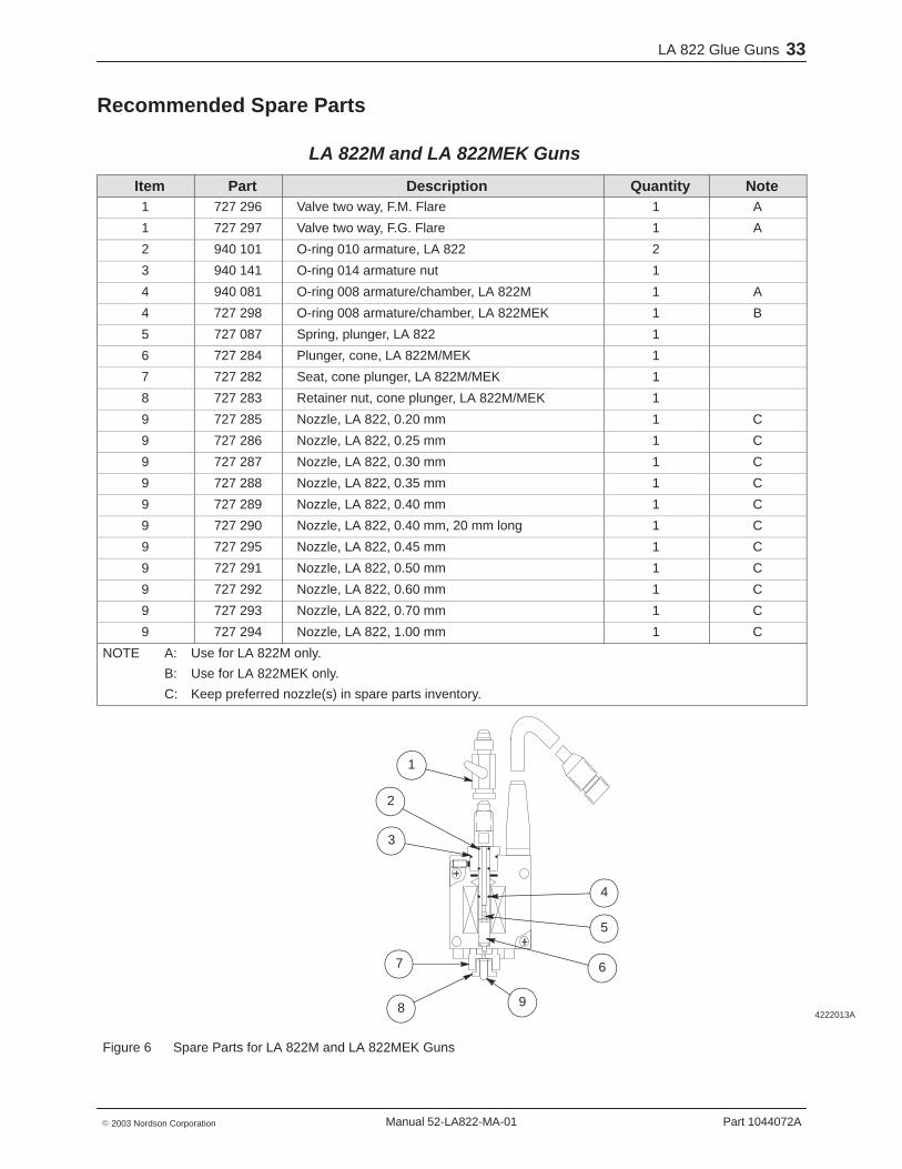
Recommended Spare Parts
LA 822M and LA 822MEK Guns
Item Part Description Quantity Note1 727 296 Valve two way, F.M. Flare 1 A
1 727 297 Valve two way, F.G. Flare 1 A
2 940 101 O-ring 010 armature, LA 822 2
3 940 141 O-ring 014 armature nut 1
4 940 081 O-ring 008 armature/chamber, LA 822M 1 A
4 727 298 O-ring 008 armature/chamber, LA 822MEK 1 B
5 727 087 Spring, plunger, LA 822 1
6 727 284 Plunger, cone, LA 822M/MEK 1
7 727 282 Seat, cone plunger, LA 822M/MEK 1
8 727 283 Retainer nut, cone plunger, LA 822M/MEK 1
9 727 285 Nozzle, LA 822, 0.20 mm 1 C
9 727 286 Nozzle, LA 822, 0.25 mm 1 C
9 727 287 Nozzle, LA 822, 0.30 mm 1 C
9 727 288 Nozzle, LA 822, 0.35 mm 1 C
9 727 289 Nozzle, LA 822, 0.40 mm 1 C
9 727 290 Nozzle, LA 822, 0.40 mm, 20 mm long 1 C
9 727 295 Nozzle, LA 822, 0.45 mm 1 C
9 727 291 Nozzle, LA 822, 0.50 mm 1 C
9 727 292 Nozzle, LA 822, 0.60 mm 1 C
9 727 293 Nozzle, LA 822, 0.70 mm 1 C
9 727 294 Nozzle, LA 822, 1.00 mm 1 C
NOTE A: Use for LA 822M only.
B: Use for LA 822MEK only.
C: Keep preferred nozzle(s) in spare parts inventory.
4222013A
1
2
3
7
8
4
5
6
9
Figure 6 Spare Parts for LA 822M and LA 822MEK Guns
LA 822 Glue Guns34
Part 1044072A � 2003 Nordson CorporationManual 52-LA822-MA-01
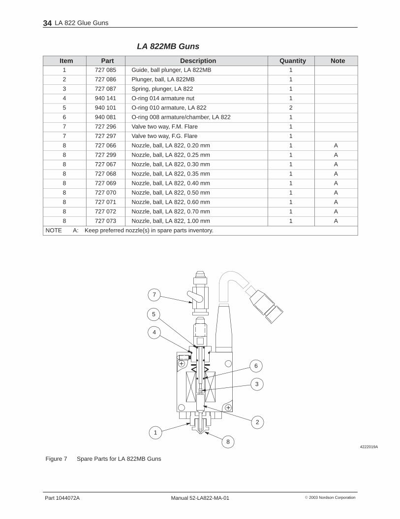
LA 822MB Guns
Item Part Description Quantity Note1 727 085 Guide, ball plunger, LA 822MB 1
2 727 086 Plunger, ball, LA 822MB 1
3 727 087 Spring, plunger, LA 822 1
4 940 141 O-ring 014 armature nut 1
5 940 101 O-ring 010 armature, LA 822 2
6 940 081 O-ring 008 armature/chamber, LA 822 1
7 727 296 Valve two way, F.M. Flare 1
7 727 297 Valve two way, F.G. Flare 1
8 727 066 Nozzle, ball, LA 822, 0.20 mm 1 A
8 727 299 Nozzle, ball, LA 822, 0.25 mm 1 A
8 727 067 Nozzle, ball, LA 822, 0.30 mm 1 A
8 727 068 Nozzle, ball, LA 822, 0.35 mm 1 A
8 727 069 Nozzle, ball, LA 822, 0.40 mm 1 A
8 727 070 Nozzle, ball, LA 822, 0.50 mm 1 A
8 727 071 Nozzle, ball, LA 822, 0.60 mm 1 A
8 727 072 Nozzle, ball, LA 822, 0.70 mm 1 A
8 727 073 Nozzle, ball, LA 822, 1.00 mm 1 A
NOTE A: Keep preferred nozzle(s) in spare parts inventory.
4222019A
7
5
4
1
8
2
3
6
Figure 7 Spare Parts for LA 822MB Guns

x
4222014A
Options A-1
Part 1044072A� 2003 Nordson Corporation Manual 52-LA822-MA-01
Appendix AOptions
TS 422 Tip Sealer
Installation The TS 422 tip sealer can be mounted on the LA 822 gun to seal/unseal thegun nozzles. The tip sealer is an air piston, spring return mechanism withan attached sealing pad. When pressurized air is applied to the piston, thesealing pad slides away from the nozzle. When pressurized air is removed,the spring pushes the pad back to cover the nozzle.
The supply of pressurized air to the tip sealer is governed by a solenoid airvalve, that is connected to the TSC 522 tip sealer control unit. The controlunit permits activation of the tip sealer either manually or automatically.Refer to TSC 522 Tip Sealer Control Unit, given later in this section.
Replacing the Tip Sealer Slide The tip sealer slide is removable. It is held in position with an engagementpin that snaps into the piston.
4222011A
Tip sealer
Engagement pin
Slide
Figure A-1 TS 422 Removing/Installing the Tip Sealer Slide

OptionsA-2
Part 1044072A � 2003 Nordson CorporationManual 52-LA822-MA-01
Shutting Off Individual Tip Sealers Only the working guns should have exposed nozzles while in use. Whenseveral guns are mounted on a machine, and only one or two are used on aparticular job, keep the tip sealers on the unused guns in the closedposition. Air shutoff valves are provided for this purpose. If a particular tipsealer is shut off, the tip sealer sliding pad remains in the closed position.
Make sure that when a tip sealer air supply is turned OFF, this same gun isnot actuated by the glue pattern controller. Turn OFF both the tip sealer andgun actuation. Turning the air supply ON returns the tip sealer to theoperating mode.
Mounting and Adjustment 1. Use the two Allen head cap screws (10 X 32 X � in.) supplied with the
tip sealer to mount the tip sealer to the gun.
CAUTION: Risk of equipment damage. Do not use longer or shorterscrews. Different size screws may damage the gun.
2. Verify that when the slide is in the sealing position, the sealing pad ispressing lightly on the nozzle. Place a thin piece of paper between thenozzle and the pad. Slide the pad to the sealing position, keeping thepaper between the pad and the nozzle, and pull on the paper. It shouldnot slide out easily. If it does, perform one or all of the following until thepaper is tight between the pad and the nozzle.
a. Make sure that the sealing pad is not dirty, torn, or worn out.Remove the retaining plate and clean with water or replace asneeded.
b. Raise the mounting position of the tip sealer on the gun to themaximum allowed to increase the pressure between the pad and thenozzle.
c. Readjust the engagement pin to increase the upward tension on theslide.
NOTE: If the engagement pin is readjusted, use a thread lockingcompound (Loctite-blue) to prevent free turning of the engagement pinrelative to the slide.
3. Make sure that the piston and O-ring are in good condition and welllubricated. Use light grease as needed.

4222012A
Options A-3
Part 1044072A� 2003 Nordson Corporation Manual 52-LA822-MA-01
TSC 522 Tip Sealer Control Unit The TSC 522 Tip Sealer Control unit is an electronic device that controls theactivation of the TS 422 tip sealer. Refer to TS 422 Tip Sealer, given earlierin this section. It has the ability to control this activation manually orautomatically.
The type of glue pattern control unit used determines whether each gluegun can be activated individually or if several guns are activated together.The TCU and PDC controllers allow activation of a group of guns connectedto the same channel. The APC controller allows activation of each gunindividually.
Automatic Operation The automatic operation of the tip sealer is activated by the trigger photosensor. When products traveling on the machine pass the trigger photosensor they should activate the sensor. An active sensor is signaled by ablinking red LED on the rear of the sensor. The first trigger of the photosensor that is detected by the tip seal control logic activates the sliding padof the sealing unit. The sliding pad retracts from the glue gun nozzle,allowing glue to flow.
NOTE: Earlier activation is possible. Normally the unit is connected to thephoto sensor that starts the glue cycle. If it is necessary to retract thesealing pad earlier, a secondary photo sensor can be mounted upstream,which—when connected to the TSC 522—causes actuation of the tip sealerwhen triggered. Consult the factory if such an arrangement is desired.
Continuous product flow sensed by the trigger photo sensor causes the tipsealer to remain retracted/open.
When products stop flowing through the machine, the trigger photo sensorstops signaling the control logic. After five seconds of inactivity, the controllogic causes the sliding pad to move forward toward the nozzle and seals it.

OptionsA-4
Part 1044072A � 2003 Nordson CorporationManual 52-LA822-MA-01
Manual Operation The remote key pad allows for remote manual activation of the tip sealerand of the glue gun. This is required for purging the guns or for checkingtheir proper operation.
� TIP SEALER Key
- Press the key marked TIP SEALER one time to retract the slidingpad and expose the nozzle.
- Press it a second time to make the sliding pad move forward andseal the nozzle.
� Numbered PURGE Keys
- Press one of the numbered purge key switches (1A, 2A, etc.) toactivate the tip sealer and associated glue gun(s).
- Press it a second time to release the purge key switch to de-activatethe tip sealer and associated glue gun(s).
Example:
� Press the 1A key to retract the tip sealer and activate the gun orgroup of guns associated with channel 1A. The glue output isslightly delayed to allow the sliding pad to clear the nozzlebefore the glue exits.
� Press the 1A key again to release it and immediately de-activatethe gun. This stops the flow of glue and allows the tip sealersliding pad to slide back into the nozzle sealing position.

Options A-5
Part 1044072A� 2003 Nordson Corporation Manual 52-LA822-MA-01
Mounting and Connections Mount the TSC 522 control unit close to the glue pattern controller to keepthe connecting cables short and put the unit in easy reach of the operator.See FigureA-2.
1. Mount the air manifold, air valve, and air filter regulator close to the gluepattern controller, but out of the way of the operator.
2. Using the magnetic mount, mount the key pad to a steel surface in anarea convenient for the operator’s reach.
3. Connect the trigger photo sensor—which is normally connected to theglue pattern control unit—to the tip sealer control unit.
NOTE: Earlier activation is possible. Normally the unit is connected tothe photo sensor that starts the glue cycle. If it is necessary to retractthe sealing pad earlier, a secondary photo sensor can be mountedupstream. Consult the factory if such an arrangement is desired.
4. Connect the cable exiting the tip sealer control unit to the trigger photosensor socket in the glue pattern controller. This is where the triggerphoto sensor is normally connected.
5. Connect the solenoid air valve to the cable exiting the tip sealer controlunit.
6. Connect the air supply (80 psi) to the air regulator and set the pressureto 80 psi.
7. Connect the 1/8 in. diameter air tubing to the tip sealer.
4222018A
ManifoldAir/Glue
Air Valve
3V
LA 822Gun
PhotoSensor
To Photo Sensor Socket
Remote Hold Cables
GluePattern
Controller(TCU/APC/PDC)
Air In80psi
GlueTank
AirFilter
60psi80psiGlueFilter
Solenoid Air Valve
RemoteKeyPad
Product Flow
TS 422Tip Sealer
TSC 522Tip Sealer Control Unit
Figure A-2 TS 422 and TS 522 Tip Sealer Control Unit Connection Diagram

OptionsA-6
Part 1044072A � 2003 Nordson CorporationManual 52-LA822-MA-01
TS 422 Tip Sealer Parts List
Item Part Description Quantity Note1 727074 Tip sealer, TS 422 1 A
2 727075 Pad, tip sealer, TS 422 1 B
3 727076 Slide assembly, TS 422 1 B
NS 727387 Tip sealer control box TSC 522 (for LA 822) 1
NS 727388 Remote key pad with 10 ft. cable (for LA 822) 1
NOTE A: Recommended spare part for LA 822 guns.
B: Recommended spare part for LA 822 guns.
NS: Not Shown
4222015A
1
2
3
Figure A-3 TS 422 Tip Sealer

Options A-7
Part 1044072A� 2003 Nordson Corporation Manual 52-LA822-MA-01
Technical Data
Performance Item LA 822M/LA 822MEK LA 822MB
Spotting max. spotting frequency 250c/sec.; spots at a 4 mm pitch at60 m/min (200 ft/min)
#17 coil: max. spottingfrequency 250 c/sec.; spots at a4 mm pitch at 60 m/min(200 ft/min)
#4 coil: max. spotting frequency500 c/sec.; spots at a 2 mm pitchat 60 m/min (200 ft/min)
Line Work max. 600 m/min (2000 ft/min)
Controller Settings The initial controller settings are listed in the following table. The gap is setto the required distance in millimeters.
NOTE: Actual settings will depend on glue pressure, adhesive viscosity,distance of nozzle tip from surface, and other variables.
Initial Controller Settings
Item LA 822M/LA 822MEK LA 822MB
Spotting on comp: 4.0 ms
off comp: 1.8 ms
on comp: 4.0 ms
off comp: 1.8 ms
Minimum Reaction Time 1.8 ms #17 coil: 1.8 ms
#4 coil: 0.8 ms
Line Work on comp: 4.0 ms
off comp: 3.5 ms
on comp: 6.7 ms
off comp: 6.3 ms
OptionsA-8
Part 1044072A � 2003 Nordson CorporationManual 52-LA822-MA-01

