l91rev8 full pg 03 21 06 - cincinnati sub-zero · without the written permission of future design...
TRANSCRIPT

User's ManualUser's Manual
LIMIT L91Microprocessor Based Limit ControllerLIMIT L91Microprocessor Based Limit Controller
LSP1PV
OP1
HSP1 SP2 LOCK
RESET
OP2
FDC-L91LIMIT
FC
Warning SymbolWarning Symbol
Use the ManualUse the Manual
This Symbol calls attention to an operating procedure, practice, orthe like, which, if not correctly performed or adhered to, could resultin personal injury or damage to or destruction of part or all of theproduct and system. Do NOT proceed beyond a warning symboluntil the indicated conditions are fully understood and met.
Installers
System Designer
Expert User
Read Chapter 1, 2
Read All Chapters
Read Page 12
NOTE:
It is strongly recommended that a process shouldincorporate a LIMIT like L91 which will shut down theequipment at a preset process condition in order topreclude possible damage to products or system.
It is strongly recommended that a process shouldincorporate a LIMIT like L91 which will shut down theequipment at a preset process condition in order topreclude possible damage to products or system.
Information in this user's manual is subject to change.without notice.
This manual is applicable for L91 units with software version1.9 and later.
Copyright a March 2006, Future Design Controls, all rightsreserved. No part of this publication may be reproduced,transmitted, transcribed or stored in a retrieval system, ortranslated into any language in any form by any meanswithout the written permission of Future Design Controls.
UM L91-Rev 82

3
Contents
Chapter 1 OverviewChapter 1 Overview
1-1 General
1-2 Ordering Code
1-3 Programming Port
1-4 Keys and Display
1-5 Menu Overview
1-6 Limit Control Operation
1-7 Parameter Descriptions
Chapter 2 InstallationChapter 2 Installation
2-1 Unpacking
2-2 Mounting
2-3 Wiring Precautions
2-4 Power Wiring
2-5 Sensor InstallationGuidelines
2-6 Thermocouple InputWiring
2-7 RTD Input Wiring
2-8 Linear DC Input Wiring
2-9 Event Input Wiring
2-10 Output 1 Wiring
2-11 Output 2 Wiring
2-12 RS 485
Chapter 3 ProgrammingChapter 3 Programming
3-1 Process Input
3-2 Limit Control
3-3 Setpoint Range
3-4 PV Shift
3-5 Digital Filter
3-6 Process Alarms
3-7 RS-485 Communication
3-8 Display Mode
3-9 Signal Conditioner DCPower Supply
3-10 Remote Reset
3-11 Remote Lock
3-12 Limit Annunciator
Chapter 4 ApplicationsChapter 4 Applications
Chapter 5 CalibrationChapter 5 Calibration
Chapter 6 SpecificationsChapter 6 Specifications
Page No Page No
5
6
7
7
12
13
16
22
22
23
25
25
26
27
28
29
30
31
32
33
34
34
35
35
36
37
38
3840
40
41
42
43
47
2-13 Ma Retransmission 32
UM L91-Rev 8
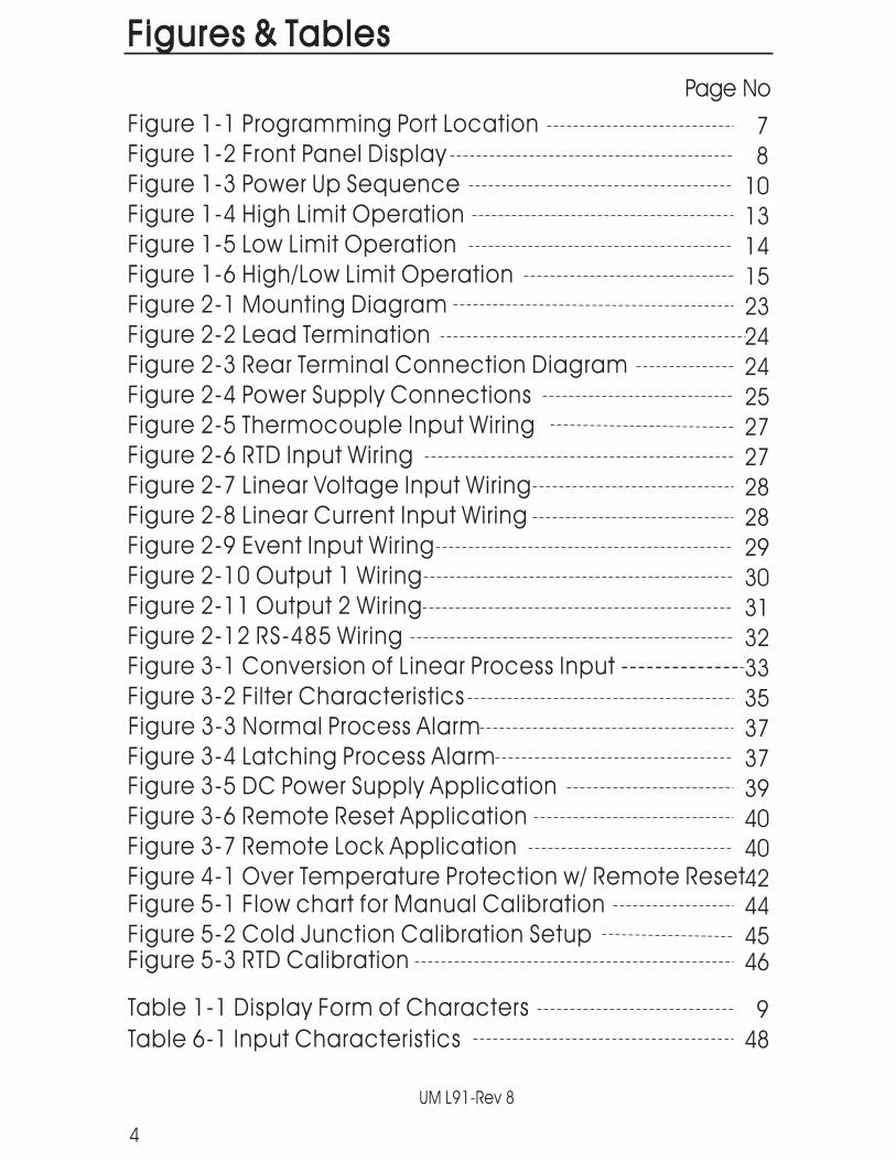
Figures & TablesFigures & Tables
Figure 3-1 Conversion of Linear Process Input --------------
Page No
7
8
10
13
14
15
23
24
24
25
27
27
28
28
29
30
31
32
33
35
37
37
39
40
4244
4546
9
48
4
Figure 1-1 Programming Port Location
Figure 1-2 Front Panel Display
Figure 1-3 Power Up Sequence
Figure 1-4 High Limit Operation
Figure 1-5 Low Limit Operation
Figure 1-6 High/Low Limit Operation
Figure 2-1 Mounting Diagram
Figure 2-2 Lead Termination
Figure 2-3 Rear Terminal Connection Diagram
Figure 2-4 Power Supply Connections
Figure 2-5 Thermocouple Input Wiring
Figure 2-6 RTD Input Wiring
Figure 2-7 Linear Voltage Input Wiring
Figure 2-8 Linear Current Input Wiring
Figure 2-9 Event Input Wiring
Figure 2-10 Output 1 Wiring
Figure 2-11 Output 2 Wiring
Figure 2-12 RS-485 Wiring
Figure 3-2 Filter Characteristics
Figure 3-3 Normal Process Alarm
Figure 3-4 Latching Process Alarm
Figure 3-6 Remote Reset Application
Figure 3-7 Remote Lock Application
Figure 4-1 Over Temperature Protection w/ Remote ResetFigure 5-1 Flow chart for Manual Calibration
Figure 5-2 Cold Junction Calibration SetupFigure 5-3 RTD Calibration
Table 1-1 Display Form of Characters
Table 6-1 Input Characteristics
Figure 3-5 DC Power Supply Application
40
UM L91-Rev 8

The limit control is a microprocessor based high or low limitsafety device with a latching output. The relay contacts open ifan abnormal condition during the process is higher than thehigh limit set point or lower than the low limit set point.
Digital communication RS-485 is available as an additionaloption. This option allows L91 to be integrated with supervisorycontrol system. An alarm output is another option. A variety ofalarm function and alarm modes can be programmed for aspecific application. The DC power supply output option is usedfor an external sensor or transmitter. The event input option canbe programmed for remote reset or remote lock signal input.The limit annunciator option can be used to energize anexternal audible alarm when limit is reached.Ma retransmission option of Process variable or setpoint is alsoavailable.
and simpleare the main features of L91.
NOTE: * Volt and Milliamp Inputs are NOT FM Approved.
L91
18-bit A to Dfast sampling rate
Two kinds of method can be used to program L91. 1. use keyson front panel to program the unit manually, 2. Use a PC andsetup software to program the unit via RS-485 port.
High accuracy, maximum flexibility, fast responseuser friendly prompts
The unit is powered by 90-264 VAC or an optional 11-26VAC/VDC power supply. It incorporates a 2 amp. form C relay forlimit control, a universal input which is fully programmable forRTD PT100, thermocouple types J, K, T, E, B, R, S, N, L, 0~60mVolt,Volt* and Milliamps*. An optional second output is available forone of the following functions: alarm output, RS-485communication, MA output, DC power supply output, limitannunciator output and event input. Alternative output optionsinclude; relay, SSR drive, Triac and Ma for retransmission.All mutually exclusive.The input signal is digitized by using a converter. Its
(5 times/second) allows the L91 to respondquickly to input changes.
Chapter 1 OverviewChapter 1 Overview
1-1 General1-1 General
5
UM L91-Rev 8

1-2 Ordering Code1-2 Ordering Code
AccessoriesOM94-6 = Isolated 1A / 240VAC Triac Output Module ( SSR )OM94-7 = 14VDC/40 ma SSR Drive moduleDC 94-1 = Isolated 20V / 25mA DC Output Power SupplyDC 94-2 = Isolated 12V / 40mA DC Output Power SupplyDC 94-3 = Isolated 5V / 80mA DC Output Power SupplyCM 96-1 = Isolated RS-485 Interface ModuleCM 96-3 = Isolated 4/20, 0/20 MA Retransmission Output ModuleCM 96-4 = Isolated 1/5, 0/5 VDC Retransmission Output ModuleCM 96-5 = Isolated 0/10 VDC Retransmission Output ModuleEI96-1 = Event Input Module
NOTE: * Volt and Milliamp Inputs are NOT FM Approved.
Power InputPower Input
4: 90 - 264 VAC, 50/60 HZ5: 11 - 26 VAC or VDC9: Special Order
1: Standard InputThermocouple: J, K, T, E, B,
R, S, N, LRTD: PT100 DIN, PT100 JISmV: 0~60 mV
2: Voltage: 0-1 V *3: Voltage : 0-10 V *4: Current: 0-20mA/4-20mA *9: Special Order *
Signal InputSignal Input
1: Form C relay rated2A/240VAC
2: Pulsed voltage todrive SSR, 5V/30mA
6: Triac Output1A / 240VAC,SSR
9: Special order
Output 1Output 1
1 2 3L91
Standard Model:L91-411090-264 VAC OperationInput: Standard InputOutput 1: RelayOption: None
Example
4
0: None1: Form A Relay 2A/240VAC2: SSR Drive 5VDC @ 30 ma6: Triac Output, 1A / 240VAC, SSR7: Isolated 20V / 25mA DC Supply8: Isolated 12V / 40 mA DC Supply9: Isolated 5V / 80mA DC SupplyA: RS-485B: Event inputC: SSR Drive 14VDC @ 40 maD: Retransmit 4/20, 0/20 MaE: Retransmit 1/5, 0/5 VDCF: Retransmit 0/10 VDCH: Special order
Option
6UM L91-Rev 8

Related ProductsRelated Products
P11A = Hand-held Programmer for L91,C91 Series ControllerSNA10A = Smart Network Adaptor for Third Party Software,
Converts 255 channels of RS-485 or RS-422 toRS-232 Network
SNA10B = Smart Network Adaptor for FD-Net Software, Converts255 channels of RS-485 or RS-422 to RS-232 Network
1-3 Programming Port1-3 Programming Port
1-4 Keys and Display1-4 Keys and Display
Note: The programming port is used for off-line setup and
calibration procedures only. Do not attempt to make any
connection to these jumpers when the unit is on-line. Port is
for bench setup only.
Note:
KEYPAD OPERATIONKEYPAD OPERATION
SCROLL KEY
This key is used to:1. Select a setpoint to be displayed.2. Select a parameter to be viewed or adjusted.3. Advance display from a parameter code to the next parameter
code
7
Figure 1-1 ProgrammingPort Location
Figure 1-1 ProgrammingPort Location
Programming Port
control board
Power board
Open the housingTop view of L91
UM L91-Rev 8
RESET
RESET
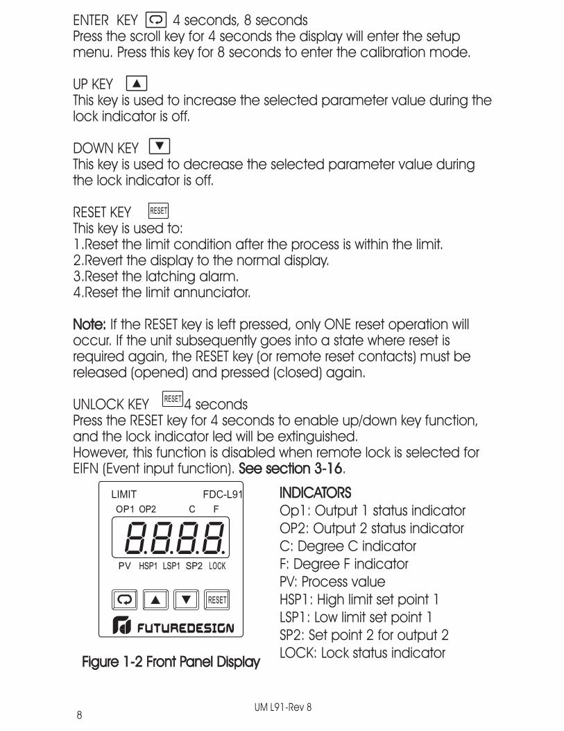
ENTER KEY 4 seconds, 8 secondsPress the scroll key for 4 seconds the display will enter the setupmenu. Press this key for 8 seconds to enter the calibration mode.
UP KEYThis key is used to increase the selected parameter value during thelock indicator is off.
DOWN KEYThis key is used to decrease the selected parameter value duringthe lock indicator is off.
RESET KEYThis key is used to:1.Reset the limit condition after the process is within the limit.2.Revert the display to the normal display.3.Reset the latching alarm.4.Reset the limit annunciator.
If the RESET key is left pressed, only ONE reset operation willoccur. If the unit subsequently goes into a state where reset isrequired again, the RESET key (or remote reset contacts) must bereleased (opened) and pressed (closed) again.
UNLOCK KEY 4 secondsPress the RESET key for 4 seconds to enable up/down key function,and the lock indicator led will be extinguished.However, this function is disabled when remote lock is selected forEIFN (Event input function). .
Note:
See section 3-16
Note:
See section 3-16
8
LSP1PV
OP1
HSP1 SP2 LOCK
RESET
OP2
FDC-L91LIMIT
FC
Figure 1-2 Front Panel DisplayFigure 1-2 Front Panel Display
INDICATORSOp1: Output 1 status indicatorOP2: Output 2 status indicatorC: Degree C indicatorF: Degree F indicatorPV: Process valueHSP1: High limit set point 1LSP1: Low limit set point 1SP2: Set point 2 for output 2LOCK: Lock status indicator
INDICATORS
UM L91-Rev 8

For a number with decimal point the display will be shifted one digit right:
-19999 will be displayed as:
45536 will be displayed as:
How to display a 5-digit number :How to display a 5-digit number :
-199.99 will be displayed as -199.9, 4553.6 will be displayed as 4553
For a number without decimal point the display will be divided into twoalternating phases:
: These characters are displayed differently.
Table 1-1 Display Form of CharactersTable 1-1 Display Form of Characters
A E I N S X
B F J O T Y
C G K P U Z
c H L Q V ?
D h M R W =
DISPLAY FORMDISPLAY FORM
-9999 will be displayed as:
NORMAL DISPLAY
ABNORMAL DISPLAY
During normal operation, the unit can be configured to display theprocess value, high limit or low limit set point ( HSP1 or LSP1dependent on OUT1 selection ) or the word SAFE.
Whenever the process is outside the normal range, the processvalue will be displayed.
NORMAL DISPLAY
ABNORMAL DISPLAY
9UM L91-Rev 8

SENSOR BREAK DISPLAYIf a break is detected in the sensor circuit, the display will show:SENSOR BREAK DISPLAY
POWER UP SEQUENCEPOWER UP SEQUENCE
10
All segments of display and indicators areleft off for 0.5 second.
All segments of display and indicators arelit for 1 second.
Display program code of the product for1 second. The left diagram showsprogram no.1 with version 21.
Display Date Code for 1 second. The leftdiagram shows Year 2001, MonthFebruary (2), Date 25'th. This means thatthe product is produced on February25'th, 2001. Note that the month codeis for is for and is
AOctober, B November C
AOctober, B November C
A-D FAILURE DISPLAYIf failure is detected in the A-D converter circuit, the display willshow:
A-D FAILURE DISPLAY
LSP1PV
OP1
HSP1 SP2 LOCK
RESET
OP2
FDC-L91LIMIT
LFLFLCLC
LSP1PV
OP1
HSP1 SP2 LOCK
RESET
OP2
FDC-L91LIMIT
LFLFLCLC
LSP1PV
OP1
HSP1 SP2 LOCK
RESET
OP2
FDC-L91LIMIT
LFLFLCLC
RESET
FDC-L91LIMIT
UM L91-Rev 8

Display the serial number ( 001~999 ) for 1second.
Display the hours used for 2 seconds. The leftdiagram shows that the unit has been usedfor 23456.7 hours since production.
Figure 1-3 Power Up SequenceFigure 1-3 Power Up Sequence
11
LSP1PV
OP1
HSP1 SP2 LOCK
RESET
OP2
FDC-L91LIMIT
LFLFLCLC
LSP1PV
OP1
HSP1 SP2 LOCK
RESET
OP2
FDC-L91LIMIT
LFLFLCLC
LSP1PV
OP1
HSP1 SP2 LOCK
RESET
OP2
FDC-L91LIMIT
LFLFLCLC
UM L91-Rev 8

1-5 Menu Overview1-5 Menu Overview
PV Valueor SAFEPV Valueor SAFE
HSP1 ValueHSP1 Value
LSP1 ValueLSP1 Value
SP2 ValueSP2 Value
INPT
UNIT
RESO
IN.LO
IN.HI
SHIF
FILT
OUT1
O1.HY
HSP.L
HSP.H
LSP.L
LSP.H
OUT2
ADDR
BAUD
PARI
AOFN
AOLO
AOHI
AL.FN
AL.MD
AL.HY
AL.FT
EIFN
DISP
Input type
Process unit
Display resolutionLow scale value for linearinputHigh scale value for linearinput
PV shift (offset) value
PV filter time constant
Output 1 function
Output 1 hysteresis value
Lower limit of HSP1
Lower limit of LSP1
Upper limit of HSP1
Upper limit of LSP1
Output 2 functionAddress for digitalcommunication
Baud rate
Parity bit
Analog output function
Analog output low scale
Analog output high scale
Alarm function
Alarm mode
Alarm hysteresis value
Alarm failure transfer
Event input function
Normal display format
Processvalue
High limitsetpoint 1value
Low limitsetpoint 1value
Set point 2value
Pressfor 4 sec.
Setup ModeSetup Mode
12
PV.HI
PV.LO
Max. historical PV
Min. historical PV
T.ABN Abnormal time
UM L91-Rev 8

The flow charts show a complete listing of parameters. For theactual application the number of available parameters isdependent on the setup conditions, and should be less than thatshown in the flow charts.
Press key for 4 seconds to enable up/down key function, andthe LOCK indicator led will be extinguished.
If Hi. is selected for OUT1, the unit will perform high limit control. When poweris applied the OUT1 relay is de-energized. After 6.5 seconds self-test period,if the process is below the high limit set point (HSP1), the output 1 relay willbe energized and OP1 indicator will go off. If the process goes above thehigh limit set point, the relay will be de-energized, the OP1 indicator will goon and the display will show the process value. After the process falls belowthe high limit set point and the RESET key is pressed or the remote reset inputis applied, the relay will be energized and the OP1 indicator will go off.
NOTE: Hysteresis is safe-sided.
RESET
Note 1.Note 1.
Note 2.Note 2.
1-6 Limit Control Operation1-6 Limit Control Operation
HIGH LIMIT OPERATIONHIGH LIMIT OPERATION
HSP1
ON
OFF
OUT1 Relay
A, B ,C=Reset is appliedO1.HY= Output1 hysteresis
Figure 1-4 High Limit OperationFigure 1-4 High Limit Operation
PV
A B C
13
HSP1 O1.HY
UM L91-Rev 8
LOW LIMIT OPERATIONLOW LIMIT OPERATION
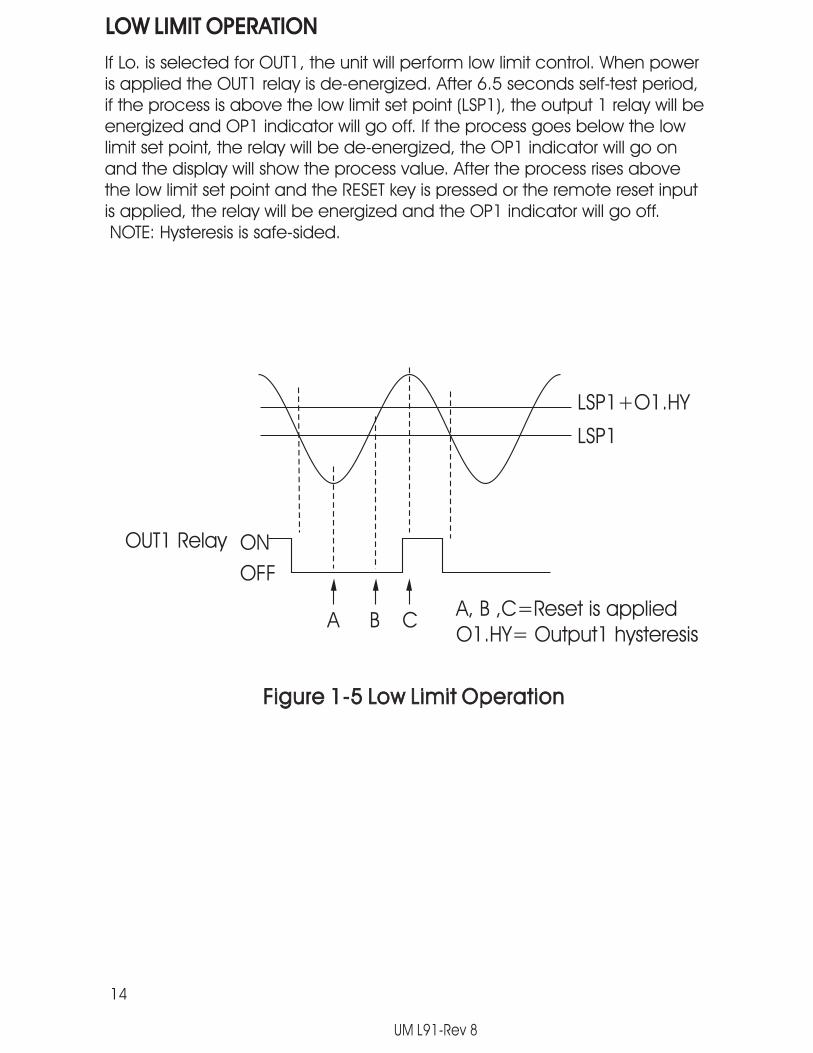
If Lo. is selected for OUT1, the unit will perform low limit control. When poweris applied the OUT1 relay is de-energized. After 6.5 seconds self-test period,if the process is above the low limit set point (LSP1), the output 1 relay will beenergized and OP1 indicator will go off. If the process goes below the lowlimit set point, the relay will be de-energized, the OP1 indicator will go onand the display will show the process value. After the process rises abovethe low limit set point and the RESET key is pressed or the remote reset inputis applied, the relay will be energized and the OP1 indicator will go off.NOTE: Hysteresis is safe-sided.
LSP1+O1.HY
LSP1
ON
OFF
OUT1 Relay
A, B ,C=Reset is appliedO1.HY= Output1 hysteresis
Figure 1-5 Low Limit OperationFigure 1-5 Low Limit Operation
A B C
14
UM L91-Rev 8

HIGH/LOW LIMIT OPERATIONHIGH/LOW LIMIT OPERATION
If Hi.Lo is selected for OUT1, the unit will perform high/low limit control. Whenpower is applied the OUT1 relay is de-energized. After 6.5 seconds self-testperiod, if the process is below the high limit set point (HSP1) and above thelow limit set point (LSP1), the output 1 relay will be energized and OP1indicator will go off. If the process goes above the high limit set point orbelow the low limit set point, the relay will be de-energized, the OP1indicator will go on and the display will show the process value. After theprocess is within the normal operation range, and the RESET key is pressedor the remote reset input is applied, the relay will be energized and theOP1 indicator will go off. NOTE: Hysteresis is safe-sided.
LSP1+O1.HY
HSP1
LSP1
HSP1 O1.HY
ON
OFF
OUT1 Relay
A, B, C, D, E, F =Reset is appliedO1.HY= Output1 hysteresis
Figure 1-6 High/Low Limit OperationFigure 1-6 High/Low Limit Operation
A B C D E F
15
UM L91-Rev 8

1-7 Parameter Descriptions1-7 Parameter Descriptions
ParameterNotation
ParameterDescription
Range DefaultValue
HSP1
LSP1
INPT
SP2
High Limit Set point 1
Low Limit Set point 1
Input Type Selection
Set point 2 Value forOutput 2
Low: HSP.LHigh: HSP.H
Low: LSP.LHigh: LSP.H
See Table 6-1
100.0 C(212.0 F)
0 C(32.0 F)
90.0 C(194.0 F)
0 : J typethermocouple
1 : K typethermocouple
2 : T typethermocouple
3 : E typethermocouple
4 : B typethermocouple
5 : R typethermocouple
6 : S typethermocouple
7 : N typethermocouple
8 : L typethermocouple
9 : PT100ohms DIN curve
10 : PT100ohms JIS curve
1( 0 )
16
UM L91-Rev 8

11 : 4~20mA linear current
12 : 0~20mA linear current*
13 : 0~60mV linear voltage
14 : 0~1 Vlinear voltage
15 : 0~5 Vlinear voltage
16 : 1~5 Vlinear voltage
17 : 0~10Vlinear voltage
ParameterNotation
ParameterDescription
Range DefaultValue
INPT Input Type Selection1
( 0 )
0( 1 )
17
UNIT
RESO
Process Unit
Display Resolution
0 :Degree C unit
2 :Process unit
1 :Degree F unit
0 :No decimal point
1 :1 decimal point
2 :2 decimal point
3 :3 decimal point
1
IN.LOLow Scale Value forLinear Input
Low: -19999High: IN.HI 0
*
*
*
*
*
NOTE: Inputs 11, 12, 14, 15, 16, and 17 are NOT FM Approved.
UM L91-Rev 8

IN.HI
SHIF
High Scale Value forLinear Input
PV Shift ( offset )Value
Low: IN.LOHigh: 45536
Low: -200.0 C(-360.0 F)
High: 200.0 C(360.0 F)
100.0
0.0
ParameterNotation
ParameterDescription
Range DefaultValue
FILTPV Filter TimeConstant
3 : 1 secondtime constant
0 : 0 secondtime constant
4 : 2 secondstime constant
5 : 5 secondstime constant
6 : 10 secondstime constant
7 : 20 secondstime constant
8 : 30 secondstime constant
9 : 60 secondstime constant
1 : 0.2 secondtime constant
2 : 0.5 secondtime constant
2
OUT1 Output 1 Function
2 : High limitcontrol
3 : Low limitcontrol
2
18
4 : High/Lowlimit control
UM L91-Rev 8

ParameterNotation
ParameterDescription
Range DefaultValue
19
O1.HY Output 1 HysteresisValue
Low: 0.1High: 10.0 BC (18.0 BF) 0.1
HSP.L
LSP.L
HSP.H
LSP.H
Lower Limit of HSP1
Lower Limit of LSP1
Upper Limit of HSP1
Upper Limit of LSP1
Low: -19999High: HSP.H
Low: -19999High: LSP.H
Low: HSP.LHigh: 45536
Low: LSP.LHigh: 45536
0 C(32.0 F)
0 C(32.0 F)
1000.0 C(1832.0 F)
-100.0 C(-148.0 F)
OUT 2 Output 2 Function
5 :Event input
0 : No function
1 : DC powersupply output
2 : RS-485Communication
3 :Alarm output
ADDRAddress Assignmentof Digital COMM
Low: 1High: 255
BAUD Baud Rate of DigitalCOMM
0 : 0.3 Kbits/sbaud rate
1 : 0.6 Kbits/sbaud rate
4 : Limitannunciator
4
1
6 :4-20mA analogretransmission output
7 :0-20mA analogretransmission output
8 :0-1V analogretransmission output
9 :0-5V analogretransmission output
10 :1-5V analogretransmission output
11 :0-10V analogretransmission output
UM L91-Rev 8

ParameterNotation
ParameterDescription
Range DefaultValue
6 : 14.4 Kbits/sbaud rate
7 : 19.2 Kbits/sbaud rate
8 : 28.8 Kbits/sbaud rate
9 : 38.4 Kbits/sbaud rate
BAUD Baud Rate of DigitalCOMM
5
20
PARIParity Bit of DigitalCOMM
0 : 8 biteven parity
1 : 8 bitodd parity
2 : 8 bitnone parity
0
5 : 9.6 Kbits/sbaud rate
3 : 2.4 Kbits/sbaud rate
4 : 4.8 Kbits/sbaud rate
2 : 1.2 Kbits/sbaud rate
AOFNAnalog OutputFunction
0 : Processvalue
1 : High LimitSet point 1
2 : Low LimitSet point 1
0
AOLO Analog Output LowScale Value
Low: -19999High: 45536
0 C(32.0 F )
AOHI Analog Output HighScale Value
Low: -19999High: 45536
100.0 C(212.0 F )
6 : Processvalue high alarm
7 : Processvalue low alarm
AL.FN Alarm function 6
UM L91-Rev 8

0 : Alarmoutput goes offas unit fails
1 : Alarmoutput goes onas unit fails
21
ParameterNotation
ParameterDescription
Range DefaultValue
AL.FT Alarm failure transfer 1
EIFN Event input function
0 : Displayprocess value
1 : DisplayHSP1 or LSP1 value
2 : Displaythe word SAFE
2 : Remotelock for the unit
1 : Remotereset for output 1,output 1 on.
0 : No eventfunction
0
DISP Normal displayformat
0
PV.HIHistorical Max. valueof PV
Low: -19999High: 45536
PV.LOHistorical Min. valueof PV
Low: -19999High: 45536
T.ABNAccumulated timeduring abnormalcondition
Low: 0High:6553.5 minutes
0 : Normalalarm action
1 : Latchingalarm action
AL.MD Alarm mode 0
AL.HYAlarm hysteresisvalue
Low: 0.1High: 10 BC
(18.0 BF )0.1
UM L91-Rev 8
ReadOnly
ReadOnly
ReadOnly

Chapter 2 Instal lat ionChapter 2 Instal lat ion
Dangerous voltages capable of causing death arepresent in this instrument. Before installation or beginning anytroubleshooting procedures the power to all equipment must beswitched off and isolated. Units suspected of being faulty mustdisconnected and removed to a properly equipped workshop fortesting and repair. Component replacement and internalmust be made by a qualified maintenance person only.
To minimize the possibility of fire or shock hazards, do notexpose this instrument to rain or excessive moisture.
Do not use this instrument in areas under hazardousconditions such as excessive shock, vibration, dirt, moisture,corrosive gases or oil. The ambient temperature of the areas shouldnot exceed the maximum rating specified in Chapter 6.
2 - 1 Unpacking2 - 1 Unpacking
Upon receipt of the shipment remove the unit from the carton andinspect the unit for shipping damage.If any damage due to transit , report and claim with the carrier.Write down the model number, serial number, and date code forfuture reference when corresponding with our service center. Theserial number (S/N) and date code (D/C) are labeled on the boxand the housing of the unit.
2 - 2 Mounting2 - 2 Mounting
Make panel cutout to dimension shown in Figure 2-1.
22
UM L91-Rev 8
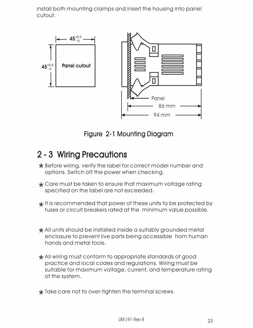
Install both mounting clamps and insert the housing into panelcutout.
45+0.5_
0
45+0.5_
0Panel cutout
Panel
86 mm
94 mm
Figure 2-1 Mounting DiagramFigure 2-1 Mounting Diagram
Before wiring, verify the label for correct model number andoptions. Switch off the power when checking.
Care must be taken to ensure that maximum voltage ratingspecified on the label are not exceeded.
It is recommended that power of these units to be protected byfuses or circuit breakers rated at the minimum value possible.
All units should be installed inside a suitably grounded metalenclosure to prevent live parts being accessible from humanhands and metal tools.
All wiring must conform to appropriate standards of goodpractice and local codes and regulations. Wiring must besuitable for maximum voltage, current, and temperature ratingof the system.
Take care not to over-tighten the terminal screws.
2 - 3 Wiring Precautions2 - 3 Wiring Precautions
*
*
*
*
*
*
23UM L91-Rev 8

Unused control terminals should not be used as jumper points asthey may be internally connected, causing damage to the unit.
Verify that the ratings of the output devices and the inputs asspecified in Chapter 6 are not exceeded.
Electric power in industrial environments contains a certainamount of noise in the form of transient voltage and spikes. Thiselectrical noise can enter and adversely affect the operation ofmicroprocessor-based controls. For thisreason we strongly recommend the use of shieldedthermocouple extension wire which connects the sensor to theunit. This wire is a twisted-pair construction with foil wrap and drainwire. The drain wire is to be attached to earth ground at thesensor end only.
*
*
*
Figure 2-2 Lead TerminationFigure 2-2 Lead Termination
Figure 2-3 Rear TerminalConnection Diagram
Figure 2-3 Rear TerminalConnection Diagram
1
2
3
4
5
6
7
8
9
10
_
_
+
+
__
++
IB
B
A
RTD
V
TX2TX2OUT2RS-485RetransmitEvent Input
OUT2RS-485RetransmitEvent Input TX1TX1
90-264VAC47-63 Hz10VA
90-264VAC47-63 Hz10VA
OUT1OUT1
2A240 VAC2A240 VAC
2A240 VAC
2A240 VAC
PTAPTA
LL
NN
NCNC
NONO
CC
7.0mm max.3.2mm min.
24
UM L91-Rev 8
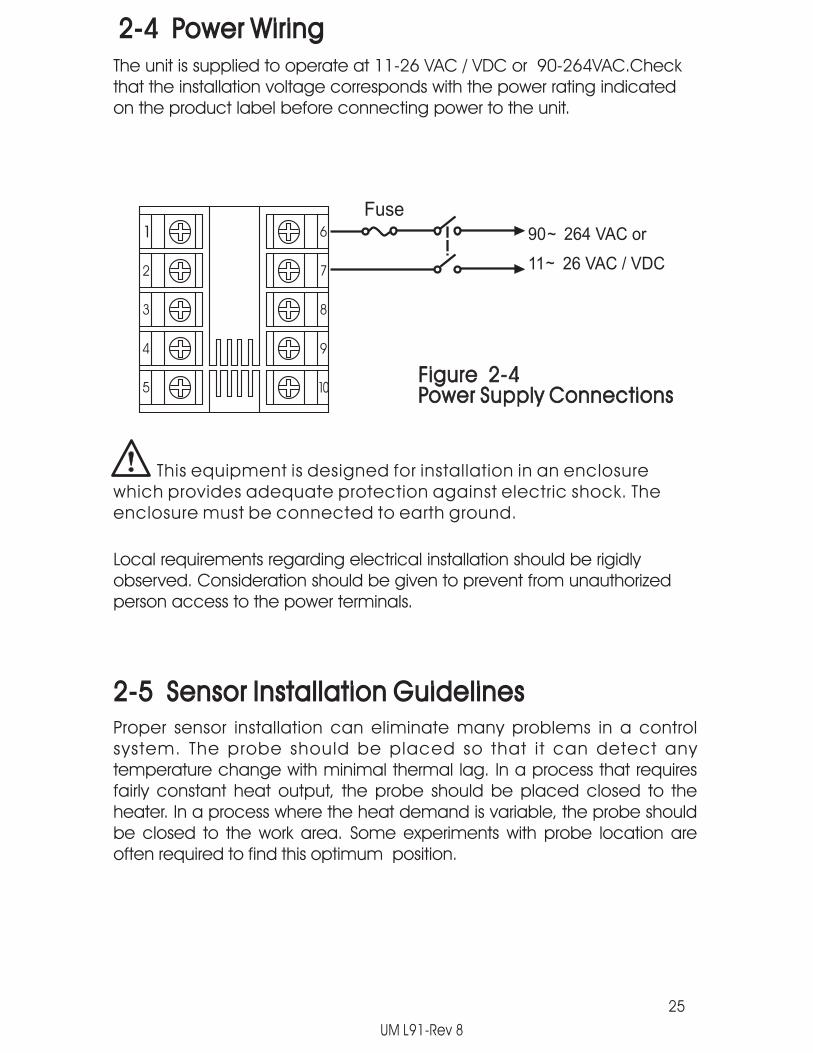
2-4 Power Wiring2-4 Power Wiring
The unit is supplied to operate at 11-26 VAC / VDC or 90-264VAC.Checkthat the installation voltage corresponds with the power rating indicatedon the product label before connecting power to the unit.
90 264 VAC or
11 26 VAC / VDC~
~
Fuse
Figure 2-4Power Supply ConnectionsFigure 2-4Power Supply Connections
1
2
3
4
5
6
7
8
9
10
This equipment is designed for installation in an enclosurewhich provides adequate protection against electric shock. Theenclosure must be connected to earth ground.
Local requirements regarding electrical installation should be rigidlyobserved. Consideration should be given to prevent from unauthorizedperson access to the power terminals.
Proper sensor installation can eliminate many problems in a controlsystem. The probe should be placed so that it can detect anytemperature change with minimal thermal lag. In a process that requiresfairly constant heat output, the probe should be placed closed to theheater. In a process where the heat demand is variable, the probe shouldbe closed to the work area. Some experiments with probe location areoften required to find this optimum position.
2-5 Sensor Installation Guidelines2-5 Sensor Installation Guidelines
25
UM L91-Rev 8

26
In a liquid process, addition of a stirrer will help to eliminate thermallag. Since the thermocouple is basically a point measuring device,placing more than one thermocouple in parallel will provide anaverage temperature readout and produce better results in mostair heated processes.
Proper sensor type is also a very important factor to obtain precisemeasurements. The sensor must have the correct temperaturerange to meet the process requirements. In special processes thesensor might need to have different requirements such as leak-proof, anti-vibration, antiseptic, etc.
Standard thermocouple sensor limits of error are +/-4degrees F(+/- 2 degrees C ) or 0.75% of sensed temperature (half that forspecial ) plus drift caused by improper protection or an over-temperature occurrence. This error is far greater than controllererror and cannot be corrected at the sensor except by properselection and replacement.
Thermocouple input connections are shown in Figure 2-5. Thecorrect type of thermocouple extension lead-wire orcompensating cable must be used for the entire distancebetween the unit and the thermocouple, ensuring that the correctpolarity is observed throughout. Joints in the cable should be
If the length of thermocouple plus the extension wire is too long, itmay affect the temperature measurement. A 400 ohms K type ora 500 ohms J type thermocouple lead resistance will produceapproximately 1 degree C temperature error .
2-6 Thermocouple Input Wiring2-6 Thermocouple Input Wiring
UM L91-Rev 8
1
2
3
4
5
6
7
8
9
10
+
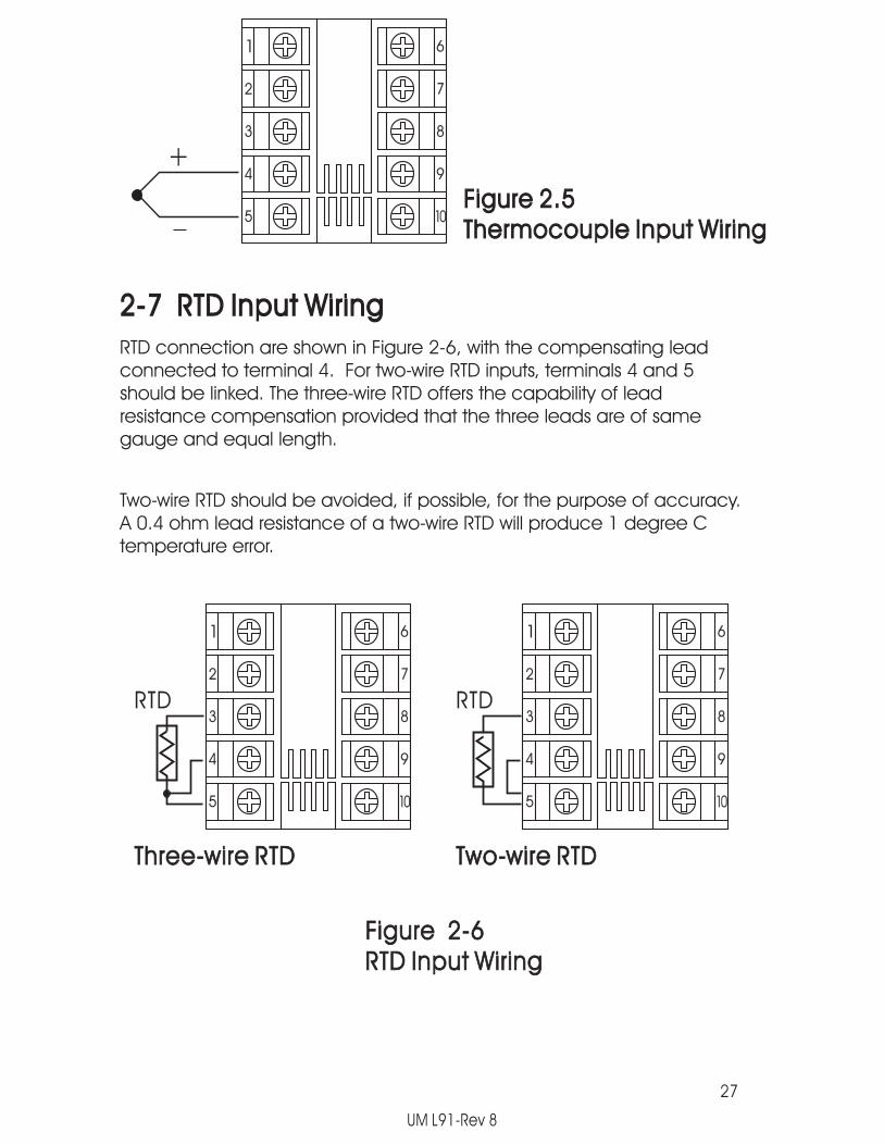
Figure 2.5Thermocouple Input WiringFigure 2.5Thermocouple Input Wiring
RTD connection are shown in Figure 2-6, with the compensating leadconnected to terminal 4. For two-wire RTD inputs, terminals 4 and 5should be linked. The three-wire RTD offers the capability of leadresistance compensation provided that the three leads are of samegauge and equal length.
2-7 RTD Input Wiring2-7 RTD Input Wiring
Two-wire RTD should be avoided, if possible, for the purpose of accuracy.A 0.4 ohm lead resistance of a two-wire RTD will produce 1 degree Ctemperature error.
1
2
3
4
5
6
7
8
9
10
RTD
1
2
3
4
5
6
7
8
9
10
RTD
Three-wire RTDThree-wire RTD Two-wire RTDTwo-wire RTD
Figure 2-6RTD Input WiringFigure 2-6RTD Input Wiring
27
UM L91-Rev 8

2-8 Linear DC Input Wiring2-8 Linear DC Input Wiring
DC linear voltage and linear current connections are shown in Figure 2-7and Figure 2-8 .
Figure 2.7Linear Voltage WiringInputFigure 2.7Linear Voltage Input Wiring
Figure 2.8Linear Current Wiring *InputFigure 2.8Linear Current Input Wiring *
0~60mV, 0~1V,0~5V, 1~5V,0~10V
0~60mV, 0~1V,0~5V, 1~5V,0~10V
+
1
2
3
4
5
6
7
8
9
10
1
2
3
4
5
6
7
8
9
10
0~20mA or4~20mA0~20mA or4~20mA
+
28
*
NOTE: Volt and Milliamp inputs are NOT FM Approved.
UM L91-Rev 8

2-9 Event Input wiring2-9 Event Input wiring
The event input can accept a switch signal as well as an open collectorsignal. The event input function (EIFN) is activated as the switch is closedor an open collector (or a logic signal ) is pulled down.
Open CollectorInputOpen CollectorInput
Switch InputSwitch Input
1
2
3
4
5
6
7
8
9
10
+
1
2
3
4
5
6
7
8
9
10
Figure 2-9Event Input WiringFigure 2-9Event Input Wiring
29
UM L91-Rev 8

2-10 Output 1 Wir ing2-10 Output 1 Wir ing
1
2
3
4
5
6
7
8
9
10
1
2
3
4
5
6
7
8
9
10
1
2
3
4
5
6
7
8
9
10
120V/240VMains Supply120V/240VMains Supply
Max. 2AResistiveMax. 2AResistive
Load
Relay or Triac OutputDirect DriveRelay or Triac OutputDirect Drive
Figure 2-10Output 1 WiringFigure 2-10Output 1 Wiring
To ControllerOutputTo ControllerOutput
ThreePhaseDeltaHeaterLoad
ThreePhaseDeltaHeaterLoad
No FuseBreakerNo FuseBreaker
Contactor
120V /240VMains Supply120V /240VMains Supply
ThreePhaseHeaterPower
ThreePhaseHeaterPower
To ControllerOutputTo ControllerOutput
Relay or Triac (SSR)Output to DriveContactor
Relay or Triac (SSR)Output to DriveContactor
+
30mA / 5VPulsedVoltage
30mA / 5VPulsedVoltage
Internal CircuitInternal Circuit
+
5V
0V
10
9
33
33
Load120V /240VMains Supply120V /240VMains Supply
+
+
_
_
SSR
Pulsed Voltageto Drive SSRPulsed Voltageto Drive SSR
To ControllerOutputTo ControllerOutput
30
UM L91-Rev 8

1
2
3
4
5
6
7
8
9
10
2-11 Output 2 Wir ing2-11 Output 2 Wir ing
LOAD120V/240VSupply
Relay or Triac OutputRelay or Triac Output
1
2
3
4
5
6
7
8
9
10
1
2
3
4
5
6
7
8
9
10
LOAD
+
_
SSR
120V/240VSupply
Pulsed Voltage to Drive SSRPulsed Voltage to Drive SSR
+
+
Sensoror
Transmitter
DC Power Supply OutputDC Power Supply Output
31
Figure 2-11 Output 2 WiringFigure 2-11 Output 2 Wiring
Max. 2AResistive
UM L91-Rev 8
32
1
2
3
4
5
6
7
8
9
10
1
2
3
4
5
6
7
8
9
10
1
2
3
4
5
6
7
8
9
10
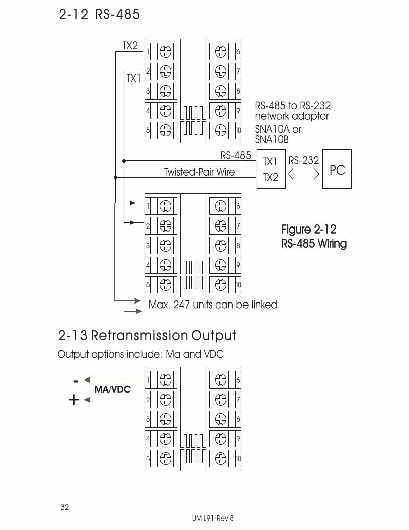
2-12 RS-4852-12 RS-485
Max. 247 units can be linked
SNA10A orSNA10B
RS-485 to RS-232network adaptor
TX1
TX2PC
RS-232
TX2
TX1
RS-485
Twisted-Pair Wire
Figure 2-12RS-485 WiringFigure 2-12RS-485 Wiring
UM L91-Rev 8
2-13 Retransmission Output2-13 Retransmission Output
+-
Output options include: Ma and VDC
MA/VDC

Chapter 3 ProgrammingChapter 3 Programming
3-1 Process Input3-1 Process Input
Press for 4 seconds to enter setup mode. Press to select theparameter. The display will indicate the parameter symbol and the value( or selection ) for that parameter.
INPT: Selects the sensor type and signal type for the process input.INPT:
UNIT: Selects the process unit.UNIT:
RESO: Selects the location of the decimal point (Resolution) formost (not all) process related parameters.
RESO:
IN.LO: Selects the low scale value for the Linear type inputIN.LO:
IN.HI: Selects the high scale value for the Linear type inputIN.HI:
Hidden if: T/C or RTD type is selected for INPTHidden if:
Hidden if: T/C or RTD type is selected for INPTHidden if:
How to use IN.LO and IN.HI:How to use IN.LO and IN.HI:If 4-20mA is selected for INPT, let SL specifies the input signal low (ie.4mA), SH specifies the signal high (ie. 20mA), S specifies the currentinput signal value, the conversion curve of the process value isshown as follows:
IN.LO
process value
PV
IN.HI
SL SHSinput signal
Figure 3-1 Conversion Curve forLinear Type Process Value
Figure 3-1 Conversion Curve forLinear Type Process Value
33
UM L91-Rev 8

34
3-2 Limit Control3-2 Limit Control
Formula: PV = IN.LO + ( IN.HI IN.LO )Formula:S-SL
SH-SLExample: a 4-20 mA current loop pressure transducer with range
0 - 15 kg/cm , is connected to input, then perform thefollowing setup:
Example:2
INPT = 4-20 mAUNIT = PURESO = 1-DP
IN.LO = 0.0IN.HI = 15.0
Of course, you may select other value for RESO to alterthe resolution.
O1.HY: Output 1 hysteresis value. The hysteresis value is adjusted toa proper value to eliminate the relay jitter in a noisyenvironment.
O1.HY:
3-3 Set Point Range3-3 Set Point RangeHSP.L : Lower limit of HSP1
Hidden if LO is selected for OUT1HSP.L :
HSP.H : Upper limit of HSP1Hidden if LO is selected for OUT1
HSP.H :
LSP.L : Lower limit of LSP1Hidden if HI is selected for OUT1
LSP.L :
LSP.H : Upper limit of LSP1Hidden if HI is selected for OUT1
LSP.H :
HSP.L and HSP.H in setup menu are used to confine the adjustmentrange of HSP1. LSP.L and LSP.H are used to confine the adjustmentrange of LSP1.
UM L91-Rev 8

3-4 PV Shift3-4 PV Shift
In certain application it is desirable to shift the indicatedvalue from its actual value. This can be easily accomplishedwith this unit by using the PV shift function.
Cycle the unit to the SHIF parameter by using the scroll key.The number you adjust here, either positive or negative, willbe added to the actual value. The SHIF function will alter PValter PV
SHIF: PV shift (input correction) valueSHIF:
3-5 Digital Fi l ter3-5 Digital Fi l terIn certain applications the process value is too unstable to beread. To Improve this a programmable low pass filter incorporatedin the L91 can be used. This is a first order filter with time constantspecified by FILT parameter which is contained in setup menu. TheFILT is defaulted to 0.5 sec. before shipping. Adjust FILT to changethe time constant from 0 to 60 seconds. 0 second represents nofilter is applied to the input signal. The filter is characterized by thefollowing diagram.
35
PV
Time
FILT=0
1sec FILT=1
FILT=301sec
Figure 3-2 Filter CharacteristicsFigure 3-2 Filter Characteristics
UM L91-Rev 8

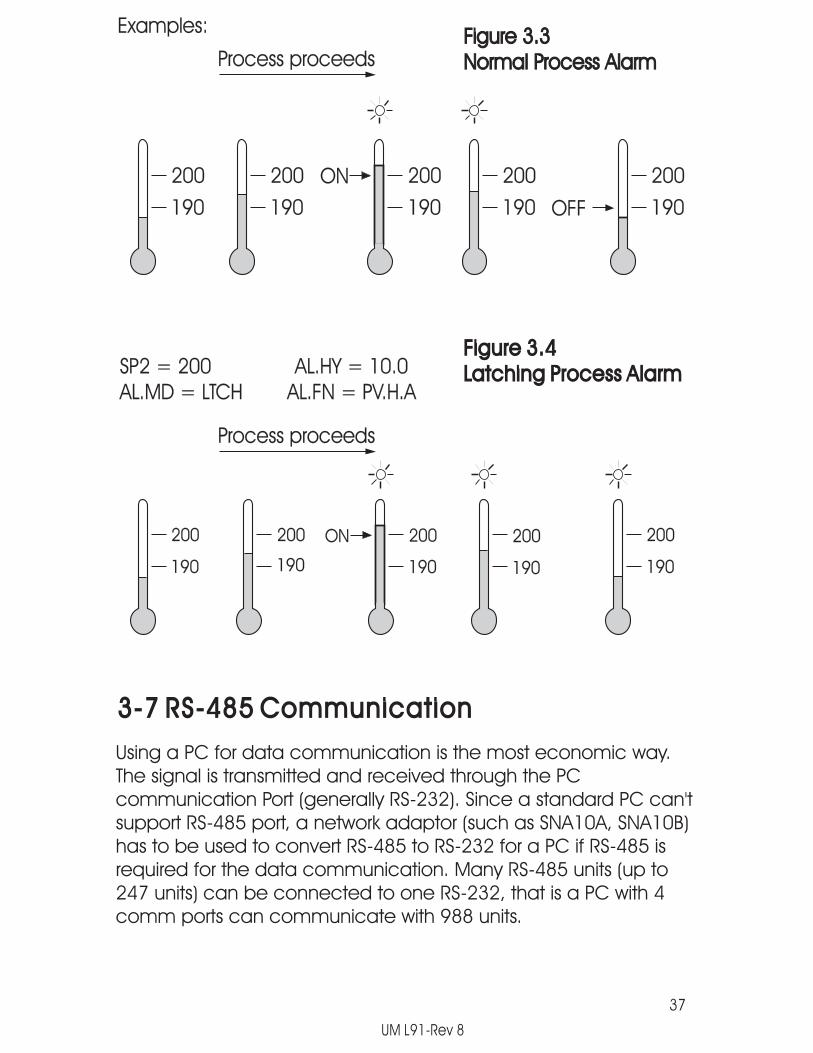
3-6 Process Alarms3-6 Process Alarms
The output 2 will perform process alarm function by selectingALM for OUT2 and PV.H.A or PV.L.A for AL.FN. If PV.H.A isselected the alarm will perform process high alarm. If PV.L.Ais selected the alarm will perform process low alarm. Theprocess alarm sets an absolute trigger level. When theprocess exceeds that absolute trigger level an alarm occurs.The trigger level is determined by SP2 (Set point 2 value) andAL.HY (Alarm hysteresis value). The hysteresis value isintroduced to avoid interference action of alarm in a noisyenvironment. Normally AL.HY can be set with a minimumvalue(0.1).
There are two types of alarm mode can be selected, theseare: normal alarm and latching alarm.
Normal Alarm: AL.MD= NORMWhen a normal alarm is selected, the alarm output is de-energized in the non-alarm condition and energized in analarm condition.
Normal Alarm: AL.MD= NORM
Latching Alarm: AL.MD= LTCHIf a latching alarm is selected, once the alarm output isenergized, it will remain unchanged even if the alarmcondition has been cleared unless the power is shut off orthe RESET key (or remote reset button) is pressed.
Latching Alarm: AL.MD= LTCH
Failure Transfer: AL.FT = OFF or ONSensor Break A-D FailureIn case of or occurs, the alarm
output will be on or off according to the selection of AL.FT.
Failure Transfer: AL.FT = OFF or ONSensor Break A-D Failure
36
SP2 = 200AL.MD = NORM
Examples:
AL.HY = 10.0AL.FN = PV.H.A
Trigger levels for process high alarm are SP2 and SP2 AL.HY.Trigger level for process low alarm are SP2+AL.HY and Sp2.
UM L91-Rev 8
37
200
190
200
190
200 200 200
190 190 190
ON
OFF
Figure 3.3Normal Process AlarmFigure 3.3Normal Process AlarmProcess proceedsProcess proceeds
200
190
200
190
200 200 200
190 190 190
ON
Figure 3.4Latching Process AlarmFigure 3.4Latching Process AlarmSP2 = 200 AL.HY = 10.0
AL.MD = LTCH AL.FN = PV.H.ASP2 = 200 AL.HY = 10.0AL.MD = LTCH AL.FN = PV.H.A
Process proceedsProcess proceeds
3-7 RS-485 Communication3-7 RS-485 Communication
Using a PC for data communication is the most economic way.The signal is transmitted and received through the PCcommunication Port (generally RS-232). Since a standard PC can'tsupport RS-485 port, a network adaptor (such as SNA10A, SNA10B)has to be used to convert RS-485 to RS-232 for a PC if RS-485 isrequired for the data communication. Many RS-485 units (up to247 units) can be connected to one RS-232, that is a PC with 4comm ports can communicate with 988 units.
Examples:
UM L91-Rev 8
38
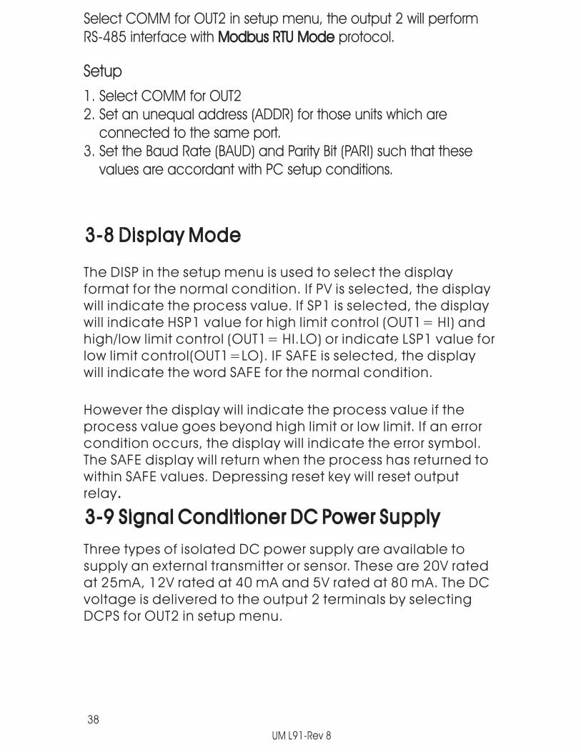
Select COMM for OUT2 in setup menu, the output 2 will performRS-485 interface with protocol.Modbus RTU ModeModbus RTU Mode
Setup
1. Select COMM for OUT22. Set an unequal address (ADDR) for those units which are
connected to the same port.3. Set the Baud Rate (BAUD) and Parity Bit (PARI) such that these
values are accordant with PC setup conditions.
3-8 Display Mode3-8 Display Mode
The DISP in the setup menu is used to select the displayformat for the normal condition. If PV is selected, the displaywill indicate the process value. If SP1 is selected, the displaywill indicate HSP1 value for high limit control (OUT1= HI) andhigh/low limit control (OUT1= HI.LO) or indicate LSP1 value forlow limit control(OUT1=LO). IF SAFE is selected, the displaywill indicate the word SAFE for the normal condition.
However the display will indicate the process value if theprocess value goes beyond high limit or low limit. If an errorcondition occurs, the display will indicate the error symbol.The SAFE display will return when the process has returned towithin SAFE values. Depressing reset key will reset outputrelay.
3-9 Signal Condit ioner DC Power Supply3-9 Signal Condit ioner DC Power Supply
Three types of isolated DC power supply are available tosupply an external transmitter or sensor. These are 20V ratedat 25mA, 12V rated at 40 mA and 5V rated at 80 mA. The DCvoltage is delivered to the output 2 terminals by selectingDCPS for OUT2 in setup menu.
UM L91-Rev 8

1
2
3
4
5
6
7
8
9
10
39
++
4-20mA
Two-lineTransmitter
Two-lineTransmitter Set
OUT2 =DC Power Supply
SetOUT2 =
Figure 3-5DC Power SupplyApplication
Figure 3-5DC Power SupplyApplication
1
2
3
4
5
6
7
8
9
10
+
+
V or mA
Three-lineTransmitteror sensor
Three-lineTransmitteror sensor
1
2
3
4
5
6
7
8
9
10
+
+
Bridge TypeSensorBridge TypeSensor
Caution:Don't use the DC power supply beyond its rating current to avoiddamage.Purchase a correct voltage to suit your external devices. Seeordering code in section 1-2.
Caution:
COM
IN
OUT
UM L91-Rev 8

3-10 Remote Reset3-10 Remote ResetIf EIFN is selected for OUT2 and REST is selected for EIFN, terminals1 & 2 will act as remote reset input. Pressing remote reset buttonwill perform the same function as pressing the RESET key. Refer to
for RESET key function.section 1-4section 1-4
Setup
OUT2 = EIFNEIFN = RESTOUT2 = EIFNEIFN = RESTRemote
Reset
1
2
3
4
5
6
7
8
9
10Figure 3-6 Remote ResetApplication
Figure 3-6 Remote ResetApplication
3-11 Remote Lock3-11 Remote Lock
If EIFN is selected for OUT2 and LOCK is selected for EIFN, terminals1 & 2 will act as remote lock input. Turning the remote lock switchon will keep all the parameter setting from been changed.
Setup
OUT2 = EIFNEIFN = LOCKOUT2 = EIFNEIFN = LOCKRemote
Lock
1
2
3
4
5
6
7
8
9
10Figure 3-7 Remote LockApplication
Figure 3-7 Remote LockApplication
40
UM L91-Rev 8

41
3-12 Limit Annunciator3-12 Limit AnnunciatorIf L_AN (Limit annunciator) is selected for OUT2, the output 2 will act as aLimit Annunciator. If the limit is or has been reached and the RESET key(or remote reset contacts)has not been pressed since the limit wasreached, then the limit annunciator output will be energized and theOP2 indicator will be lit and remain unchanged until the RESET key orremote reset input is applied.
3-13 Reference Data3-13 Reference Data
There are three reference data contained in setup menu. Thereference data are read only data. The maximum historical PV,displayed by ,which shows the maximum process valuesince the last UNLOCK operation. The minimum historical PV,displayed by , which shows the minimum process valuesince the last UNLOCK operation. The abnormal time, displayedby ,which shows the total accumulated time (minutes)during the process has been in abnormal condition since the lastUNLOCK operation.
The values of reference data will be initiated as soon as the RESETkey is pressed for 4 seconds (UNLOCK operation). After UNLOCKoperation, the PV.HI and PV.LO values will start from the currentprocess value and T.ABN value will start from zero.
UM L91-Rev 8

Chapter 4 ApplicationChapter 4 Application
1
2
3
4
5
6
7
8
9
10
1
2
3
4
5
6
7
8
9
10
TemperatureControl
Limit Control
L N
+
_
Rear View
MechanicalContactor
L91Rear View
ResetButton
Heater
42
Figure 4-1 Over Temperature Protection with Remote ResetFigure 4-1 Over Temperature Protection with Remote Reset
UM L91-Rev 8

Chapter 5 CalibrationChapter 5 Calibration
Do not proceed through this section unless there is a definiteneed to re-calibrate the controller. Otherwise, all previouscalibration data will be lost. Do not attempt re-calibrationunless you have appropriate calibration equipment. Ifcalibration data is lost, you will need to return the unit to yoursupplier who may change you a service fee to re-calibrate theunit.
Entering calibration mode will break the control loop. Make surethat if the system is allowable to apply calibration mode.
Equipment needed for calibration:(1) A high accuracy calibrator (Fluke 5520A Calibrator
recommended) with following function:0-100mA millivolt source with +/-0.005% accuracy0-10V voltage source with +/-0.005% accuracy0-20mA current source with +/-0.005% accuracy0-300 ohm resistant source with +/-0.005% accuracy
(2) A test chamber providing 25 C - 50 C temperature range(3) A switching network (SCANNER 80, optional for automatic
calibration)(4) A calibration fixture equipped with programming units
(optional for automatic calibration)(5) A PC with calibration software FD-Net and Smart Network
Adaptor SNA10B (optional for automatic calibration)
Since each unit needs 30 minutes to warm up before calibration.
The calibration procedures described in the following are a step bystep manual procedures.manual procedures.
43
Apply Enter Key (press for 8 seconds) to enter thecalibration mode. see .Figure 5-1Figure 5-1
UM L91-Rev 8

44
Normal Mode
Setup Mode
Ad0
ADG
CJTL
CJG
REF
SR
4 seconds
4 seconds
RESET
RESET
RESET
RESET
RESET
RESET
RESET
Step 1
4 seconds
Step 2
4 seconds
Step 3
4 seconds
Step 4
4 seconds
Step 5
4 seconds
Step 6
4 seconds
Figure 5-1Flow Chart for ManualCalibraton
Figure 5-1Flow Chart for ManualCalibraton
Step1: Calibrate of A to D converter.Short terminal 4 and 5, then press for at least 4 seconds.The display will blink a moment. If the display didn't blink,then the calibration has failed.
Zero
UM L91-Rev 8

Step 2: Calibrate of A to D converter.Send a span signal to terminal 4 and 5 with correct polarity.The span signal is 60 mV for thermocouple input, 1V for0-1V input, 10V for 0-10V input and 20mA for 0-20 mA input.Press for at least 4 seconds. The display will blink amoment. If the display didn't blink, then the calibration failed.
Gain
Step 3: Calibrate of .Setup the equipment according to the following diagramfor calibrating the cold junction compensation. Note that aK type thermocouple must be used.
offset cold junctionoffset cold junction
4
5
Set the calibrator to be configured as K type thermocoupleoutput. Calibrator must have an internal compensation.Send a 0.00 C signal to the unit under calibration.
Calibrator
K-TC
K+
K
NOTE: The unit under calibration is powered in a still-air roomat a temperature . Allow at least 20 minutes forwarming up.
25 +/-3 CNOTE: The unit under calibration is powered in a still-air roomat a temperature 25 +/-3 C. Allow at least 20 minutes forwarming up.
Figure 5-2Cold JunctionCalibration Setup
Figure 5-2Cold JunctionCalibration Setup
45
L91
Stay at least 20 minutes in still-air room room temperature25 +/- 3 C
UM L91-Rev 8
With CJTL on the display adjust the value to 0.00 reading.Once adjusted, Press for at least 4 seconds. The display willblink a moment. If the display didn't blink, then the calibrationfailed.
The L91 being calibrated for Cold Junction Compensation MUSTbe programmed for K t/c input, Celsius display to performingthe CJTL calibration.
prior
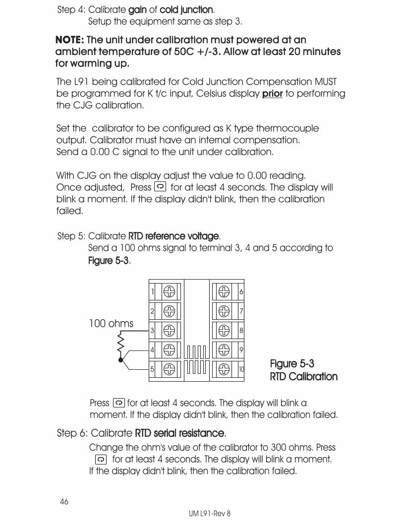
Step 4: Calibrate of .Setup the equipment same as step 3.
gain cold junctiongain cold junction
46
Step 5: Calibrate .Send a 100 ohms signal to terminal 3, 4 and 5 according to
RTD reference voltage
Figure 5-3.
RTD reference voltage
Figure 5-3
1
2
3
4
5
6
7
8
9
10
100 ohms
Figure 5-3RTD CalibrationFigure 5-3RTD Calibration
Press for at least 4 seconds. The display will blink amoment. If the display didn't blink, then the calibration failed.
Step 6: Calibrate .RTD serial resistanceRTD serial resistance
Change the ohm's value of the calibrator to 300 ohms. Pressfor at least 4 seconds. The display will blink a moment.
If the display didn't blink, then the calibration failed.
UM L91-Rev 8
The L91 being calibrated for Cold Junction Compensation MUSTbe programmed for K t/c input, Celsius display to performingthe CJG calibration.
prior
NOTE: The unit under calibration must powered at anambient temperature of 50C +/-3. Allow at least 20 minutesfor warming up.
NOTE: The unit under calibration must powered at anambient temperature of 50C +/-3. Allow at least 20 minutesfor warming up.
Set the calibrator to be configured as K type thermocoupleoutput. Calibrator must have an internal compensation.Send a 0.00 C signal to the unit under calibration.
With CJG on the display adjust the value to 0.00 reading.Once adjusted, Press for at least 4 seconds. The display willblink a moment. If the display didn't blink, then the calibrationfailed.

47
Chapter 6 SpecificationsChapter 6 SpecificationsPower
90-264 VAC, 49-63 Hz, 10 VA, 5W maximum11-26 VAC/VDC, 10 VA, 5W maximum
Power
Input18 bits
5 times/second-2 VDC minimum, 12 VDC maximum(1 minute for mA input)
A1.5 uV / C
T/C: 0.2 uV/ohm3-wire RTD: 2.6 C/ohm of resistance difference of two leads2
Resolution:Sampling:Maximum Rating:
Temperature Effect:Sensor Lead Resistance Effect:
-wire RTD: 2.6 C/ohm of resistance sum of two leads200nA
120dbBurn-out Current:Common Mode Rejection Ratio (CMRR):
InputResolution:Sampling:Maximum Rating:
Temperature Effect:Sensor Lead Resistance Effect:
Burn-out Current:Common Mode Rejection Ratio (CMRR):
Sensor Break Detection:Sensor open for TC, RTD and mV inputs,below 1 mA for 4-20 mA input,below 0.25V for 1-5 V input,unavailable for other inputs.
Sensor Break Detection:
Sensor Break Responding Time:Within 4 seconds for TC, RTD and mA inputs,0.1 second for 4-20 mA and 1-5V inputs.
Sensor Break Responding Time:
Data CommunicationInterface : RS-485 ( up to 247 units )Protocol : Modbus Protocol RTU modeAddress : 1 - 247Baud Rate : 0.3 ~ 38.4 Kbits/secData Bits : 8 bitsParity Bit : None, Even or OddStop Bit : 1 or 2 bitsCommunication Buffer : 50 bytes
Data Communication

-200 C 600 C( -328 F 1112 F )
-200 C 600 C( -328 F 1112 F )
-210 C 700 C( -346 F 1292 F )
-210 C 700 C( -346 F 1292 F )
-200 C 900 C( -328 F 1652 F )
-200 C 900 C( -328 F 1652 F )
-250 C 1300 C( -418 F 2372 F )
-250 C 1300 C( -418 F 2372 F )
0 C 1767.8 C( - 32 F 3214 F )
0 C 1767.8 C( - 32 F 3214 F )
0 C 1767.8 C( - 32 F 3214 F )
0 C 1767.8 C( - 32 F 3214 F )
0 C 1820 C( - 32 F 3308 F )
0 C 1820 C( - 32 F 3308 F )
-100 C 900 C( -148 F 1652 F )
-100 C 900 C( -148 F 1652 F )
-250 C 400 C( -418 F 752 F )
-250 C 400 C( -418 F 752 F )
-200 C 1370 C( -328 F 2498 F )-200 C 1370 C
( -328 F 2498 F )
48
Character ist ics:
Type RangeInput
ImpedanceInput
Impedance
J-120 C 1000 C
( -184 F 1832 F )-120 C 1000 C
( -184 F 1832 F )
K
T
E
B
2.2 M2.2 M
2.2 M2.2 M
2.2 M2.2 M
2.2 M2.2 M
2.2 M2.2 M
2.2 M2.2 M
2.2 M2.2 M
2.2 M2.2 M
2.2 M2.2 M
2.2 M2.2 M
PT100( DIN )PT100( DIN )
R
S
N
L
PT100( JIS )PT100( JIS )
mV
mA
V
-8mV 70mV-8mV 70mV
-3mA 27mA-3mA 27mA
-1.3V 11.5V-1.3V 11.5V
100
510 K510 K
1.3 K1.3 K
1.3 K1.3 K
Table 6-1 Input CharacteristicsTable 6-1 Input Characteristics
Accuracy@ 25 CAccuracy@ 25 C
( 200 C1820 C )
( 200 C1820 C )
+/-2 C+/-2 C
+/-2 C+/-2 C
+/-0.4 C+/-0.4 C
+/-0.4 C+/-0.4 C
+/-0.05 %+/-0.05 %
+/-2 C+/-2 C
+/-2 C+/-2 C
+/-2 C+/-2 C
+/-2 C+/-2 C
+/-2 C+/-2 C
+/-2 C+/-2 C
+/-2 C+/-2 C
+/-0.05 %+/-0.05 %
+/-0.05 %+/-0.05 %
UM L91-Rev 8

49
Logic Low:Logic High:Functions:
-10V minimum, 0.8V maximum.2V minimum, 10V maximum.
Remote reset, remote lockout.
Logic Low:Logic High:Functions:
Output 1 / Output 2Output 1 / Output 2Relay Rating:Pulsed Voltage:
2A/240 VAC, life cycles 200,000 for resistive load.Source Voltage 5V, current limiting resistance66 ohms.
Relay Rating:Pulsed Voltage:
Triac (SSR) Output1/240 VAC
20A for 1 cycle50 mA rms
3 mA rms1.5 V rms
1000 Mohms min. at 500 VDC2500 VAC for 1 minute
Rating:Inrush Current:Min. Load Current:Max. Off-state Leakage:Max. On-state Voltage:Insulation Resistance:Dielectric Strength:
Triac (SSR) OutputRating:Inrush Current:Min. Load Current:Max. Off-state Leakage:Max. On-state Voltage:Insulation Resistance:Dielectric Strength:
DC Voltage Supply Characteristics ( Installed at Output 2 )DC Voltage Supply Characteristics ( Installed at Output 2 )
Type Tolerance Max. OutputCurrent
Max. OutputCurrent
RippleVoltageRippleVoltage
IsolationBarrierIsolationBarrier
20 V20 V +/-0.5 V+/-0.5 V 25 mA25 mA 0.2 Vp-p0.2 Vp-p 500 VAC500 VAC
500 VAC500 VAC
500 VAC500 VAC
12 V12 V +/-0.3 V+/-0.3 V 40 mA40 mA 0.1 Vp-p0.1 Vp-p
5 V5 V +/-0.15 V+/-0.15 V 80 mA80 mA 0.05 Vp-p0.05 Vp-p
Event InputEvent Input
Analog RetransmissionFunctions: Process VariableOutput Signal: 4-20 mA, 0-20 mA, 0 - 5V, 1 - 5V, 0 - 10VResolution : 15 bitsAccuracy : +/-0.05 % of span +/-0.0025 %/ CLoad Resistance : 0 - 500 ohms ( for current output )
10 K ohms minimum ( for voltage output )Regulation: 0.01 % for full load changeSettling Time: 0.1 sec. (stable to 99.9 % )Breakdown Volts: 1000 VAC min.Linearity Error : +/-0.005 % of spanTemp Effect: +/-0.0025 % of span / CSaturation Low : 0 mA ( or 0V )Saturation High : 22.2 mA ( or 5.55V, 11.1V min. )Output Range :0-22.2mA(0-20mA or 4-20mA)
0-5.55V ( 0 - 5V, 1 - 5V )0 - 11.1 V ( 0 - 10V )

Operating Temperature : -10 C to 50 CStorage Temperature : -40 C to 60 CHumidity : 0 to 90 % RH ( non-condensing )Insulation Resistance : 20 Mohms min. ( at 500 VDC )Dielectric Strength : 2000 VAC, 50/60 Hz for 1 minuteVibration Resistance : 10 - 55 Hz, 10 m/s for 2 hoursShock Resistance : 200 m/s ( 20 g )Moldings : Flame retardant polycarbonateDimensions: 48 mm(W) X 48 mm(H) X 94 mm(D),
86 mm depth behind panelWeight : 150 grams
50
User Interface4-digit LED Displays:keypad:Programming Port:Communication Port:
0.4" (10mm),4 keys
For automatic setup, calibration and testing.Connection to PC for supervisory control.
User Interface4-digit LED Displays:keypad:Programming Port:Communication Port:
Limit Control: High Limit, Low limit and High/Low Limitprogrammable
Limit Control:
Digital FilterFunction:Time Constant:
First order0, 0.2, 0.5, 1, 2, 5, 10, 20, 30, 60 secondsprogrammable
Digital FilterFunction:Time Constant:
Environmental & PhysicalEnvironmental & Physical
Approval StandardsApproval Standards
Safety : UL873 ( 11'th edition, 1994 )CSA C22.2 No. 24-93EN61010-1 ( IEC1010-1 )FM Approved
Protective Class :IP30 front panel, indoor use,IP 20 housing and terminals ( with protective cover)
EMC EN61326
Safety : UL873 ( 11'th edition, 1994 )CSA C22.2 No. 24-93EN61010-1 ( IEC1010-1 )FM Approved
Protective Class :IP30 front panel, indoor use,IP 20 housing and terminals ( with protective cover)
EMC EN61326
2
2
UM L91-Rev 8

Warranty:
Limitations:
Return MaterialAuthorization:
Future Design Controls products described in this brochure arewarranted to be free from functional defects in material andworkmanship at the time the products leave Future Design Controlsfacilities and to conform at that time to the specifications set forth inthe relevant Future Design Controls manual, sheet or sheets for aperiod of TWO years after delivery to the first purchaser.
Future Design Controls provides no warranty or representations ofany sort regarding the fitness of use or application of its products bythe purchaser. Users are responsible for the selection, suitability ofthe products for their application or use of Future Design Controlsproducts.
Future Design Controls shall not be liable for any damages or losses,whether direct, indirect, incidental, special, consequential or anyother damages, costs or expenses excepting only the cost orexpense of repair or replacement of Future Design Control productsas described below.
Future Design Controls sole responsibility under the warranty, atFuture Design Controls option, is limited to replacement or repair,free of charge, or refund or purchase price within the warranty periodspecified. This warranty does not apply to damage resulting fromtransportation, alteration, misuse or abuse.
Future Design Controls reserves the right to make changes withoutnotification to purchaser to materials or processing that do not effectcompliance with any applicable specifications.
Contact Future Design Controls for Return Material Authorizationprior to returning any product to our facility.
There are no expressed or implied Warranties extending beyondthe Warranties herein and above set forth.
Warranty and Return Statement:
Future Design Controls, Inc.7524 West 98th Place, PO Box 1196,Bridgeview, IL 60455888.751.5444 - Main Office888.307.8014 - Fax866.342.5332 - Technical SuportE-mail [email protected] www.futuredesigncontrols.com
30

7524 West 98th PlaceBridgeview, IL 60455Phone - 888-599-0103Fax 708-599-1378
7524 West 98th PlaceBridgeview, IL 60455Phone - 888-599-0103Fax 708-599-1378
LIMIT FDC-L91Microprocessor Based Limit ControllerLIMIT FDC-L91Microprocessor Based Limit Controller
UM L91-Rev 8