l2130-i analyzer for isotopic h2o user’s guide appendices
TRANSCRIPT

L2130-i Analyzer for Isotopic H2O User’s Guide Appendices

Picarro L2130-i Analyzer User’s Guide Rev A, Part Number 40027, May 2012 2
TABLE OF CONTENTS
Table of Contents A-1
Introduction B-1
Conventions C-1
Safety D-1
Acronym Explanation E-1
Before Getting Started F-1
Installation G-1
Facility Preparation and Necessary Supplies ................................................ 2
Basic Analyzer Setup .................................................................................... 4
Autosampler Vaporizer A0211 Installation .................................................... 7
Manual Mode Installation ............................................................................ 19
Dual Mode Vaporizer Installation ................................................................ 23
SDM Installation .......................................................................................... 36
Basic Operation H-1
Short Overview ............................................................................................. 1
Turning on the Analyzer ................................................................................ 2
Starting the Coordinator ............................................................................... 3
Reading the GUI of the Analyzer Software ................................................... 5
Adjusting Injection Volume ............................................................................ 6
Where to find the Data .................................................................................. 7
Data Analysis of Descrete Samples of or Samples from Multiple Locations . 8
Shutdown Procedure .................................................................................... 9
In Case of Electrical Power Outage ............................................................ 10
Turning the Analyzer Software back on ...................................................... 11
Desktop Icon Explanations .......................................................................... 13
How to User the Picarro Mode Switcher ..................................................... 14

Picarro L2130-i Analyzer User’s Guide Rev A, Part Number 40027, May 2012 3
Autosampler Operation I-1
Factory Defaults ............................................................................................ 1
Autosampler Training .................................................................................... 2
Tray Holder Training ..................................................................................... 4
Wash Station Training ................................................................................... 5
Injector Port Training ..................................................................................... 6
Waste Port Training ...................................................................................... 7
Syringe Setup ............................................................................................... 8
Autosampler Methods ................................................................................. 10
Factory Supplied Methods .......................................................................... 11
Creating a New Method .............................................................................. 11
Autosampler Jobs ....................................................................................... 13
Factory Supplied Jobs ................................................................................ 13
Creating a New Job .................................................................................... 13
Appropriate Samples and Sample Preparation ........................................... 14
Starting the Autosampler ............................................................................. 15
Autosampler Maintenance .......................................................................... 16
Waste Port Septa and Glass wool .............................................................. 18
Appendix A - Status Log Messages J-1
Normal Start Up Messages ........................................................................... 1
Appendix B - List of GUI Functions K-1
Additional Tools and Information ................................................................... 1
Settings, Tools and Help Menus: .................................................................. 2
Alarm Panel .................................................................................................. 4
Digital Readouts ............................................................................................ 4
Start / Stop Data Log Button ......................................................................... 5
Data Log Filename and Path ........................................................................ 5
Data Window ................................................................................................. 5
Instrument Status .......................................................................................... 5
Data Source and Data Key Pull Down Menus ............................................... 5
Precision Pulldown menu .............................................................................. 6

Picarro L2130-i Analyzer User’s Guide Rev A, Part Number 40027, May 2012 4
Status Log Window ....................................................................................... 6
Reset Data Buffer Button .............................................................................. 6
Data Buffer Level Meter ................................................................................ 6
Graph Zooming ............................................................................................. 7
File Management .......................................................................................... 8
Setup Tool for File Management ................................................................... 9
Appendix C - Coordinators L-1
Starting the Coordinator ............................................................................... 1
Short Descriptions for Different Cordinators .................................................. 2
High Precision & High Throughput Coordinator ............................................ 4
Manual Inject Coordinator ........................................................................... 12
Dual Liquid/Vapor Coordinator .................................................................... 20
Changing Injector Port Septa ...................................................................... 29
Adjusting Injection Volume ......................................................................... 31
Appendix D – SDM Operation M-1
Theory of Operation ...................................................................................... 2
Operation ...................................................................................................... 3
Sequencer Software Operation and Recommendations ............................... 9
SDM Coordinator ....................................................................................... 12
Data Processing ......................................................................................... 14
Setting Coordinator File Output Size and Location ..................................... 17
Automatic Vaporizer Preconditioning by SDM ............................................ 18
Standards Choice ....................................................................................... 19
Bag Filling ................................................................................................... 20
In case of air bubbles .................................................................................. 22
Filed Deployment Tip .................................................................................. 23
Rotary Valve Use ........................................................................................ 24
Appendix E – Analysis of coordinator files N-1
Tray Preparation ........................................................................................... 1
Creating a Standards Database File ............................................................. 2

Picarro L2130-i Analyzer User’s Guide Rev A, Part Number 40027, May 2012 5
Running Post Processing .............................................................................. 3
Example Analysis .......................................................................................... 4
Important Notes ............................................................................................ 7
LIMITED WARRANTY O-1
SERVICE AND MAINTENANCE P-1
TROUBLESHOOTING Q-1
TRANSPORTATION AND STORAGE R-1
AUTOSAMPLER VAPORIZER A0212 INSTALLATION & TROUBLESHOOTING S-1
CREATING A BACKUP IMAGED DRIVE T-1

Picarro L2130-i Analyzer User’s Guide Rev A, Part Number 40027, May 2012 B-1
INTRODUCTION
Thank you for purchasing a Picarro product. Your Picarro Analyzer has been designed and manufactured to provide the highest quality data, easily and reliably.
This manual is an important part of your purchase as it will help familiarize you with the system and explain the numerous features. Please read this manual thoroughly before starting the installation and using your instrument.
Please don’t hesitate to contact Picarro or your authorized Picarro distributor should you have additional technical or applications questions. We provide direct e-mail and telephone support worldwide.
Contact Information
Website access to user forums: www.picarro.com
Community Website: www.picarro.com/community
Email: [email protected]
Telephone: 1 (408) 962-3950 direct or 1 (408) 962-3900, extension 3950
Fax: (408) 962-3200
Address: 3105 Patrick Henry Drive
Santa Clara
California 95054
USA
Picarro, Inc. reserves the right to change or update the contents of this manual and to change the specifications of its products at any time without prior notification. Every effort has been made to keep the information in this document current and accurate as of the date of publication or revision. However, no guarantee is given or implied that this document is error free or that it is accurate with regard to any specification. Please comment on any aspects of this manual to [email protected]. Your input is very helpful.
Picarro and the Picarro Logo are trademarks of Picarro, Inc.
2011 Picarro, Inc. All rights reserved.

Picarro L2130-i Analyzer User’s Guide Rev A, Part Number 40027, May 2012 C-1
CONVENTIONS
Throughout the manual you will see graphic icons representing important information in the text. The purpose of these icons is to provide a visual convention to alert you of a stop in the flow of the manual, where an important note or safety hazard alert is posted.
NOTE is an important procedure of which you should be aware of before proceeding.
CAUTION alerts you of a potential danger to equipment or to the user.
WARNING indicates an imminent danger to the user.
REMINDER is a helpful hint to procedures listed in the text.
Picarro L2130-i Analyzer User’s Guide Rev A, Part Number 40027, May 2012 D-1
SAFETY
The Picarro Analyzer complies with the following safety standards:
CE: IEC EN61010-1:2001 (safety) and EN61326-1:2006 (EMC) requirements for electrical equipment for measurement, control and laboratory use.
FDA/CDRH 21 CFR Parts 1040.10-11
LASER SAFETY: The Picarro Analyzer is classified as a Class 1 Embedded Laser Product
WARNING: CLASS 3B INVISIBLE LASER RADIATION WHEN OPEN. AVOID EXPOSURE TO THE BEAM.
There are lasers used inside the analyzer, emitting a maximum of 50mW of CW light in the near-infrared. There are no user serviceable components within the analyzer enclosures and so you should not open any of these enclosures within the analyzer. FAILURE TO FOLLOW THIS INSTRUCTION COULD RESULT IN EXPOSURE TO CLASS IIIB LASER RADIATION, which can permanently damage eyes and skin.
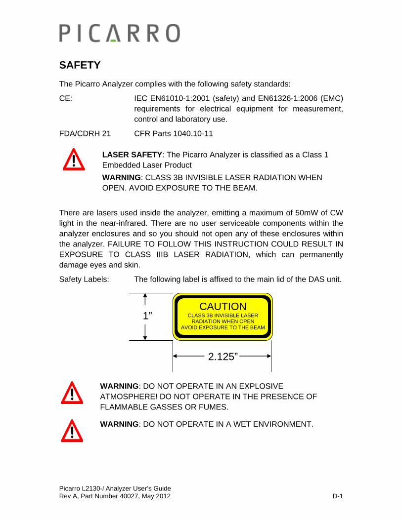
Safety Labels: The following label is affixed to the main lid of the DAS unit.
CAUTION
CLASS 3B INVISIBLE LASER RADIATION WHEN OPEN
AVOID EXPOSURE TO THE BEAM
2.125”
1”
WARNING: DO NOT OPERATE IN AN EXPLOSIVE ATMOSPHERE! DO NOT OPERATE IN THE PRESENCE OF FLAMMABLE GASSES OR FUMES.
WARNING: DO NOT OPERATE IN A WET ENVIRONMENT.
Picarro L2130-i Analyzer User’s Guide Rev A, Part Number 40027, May 2012 D-2
CAUTION: The inlet gas connector on the back panel, and its immediate vicinity, runs hot during operation of the analyzer. Take care when connecting gas lines or working at the rear of the instrument to wear protective gloves or avoid contact with these surfaces.
CAUTION: The analyzer contains HOT SURFACES and utilizes HIGH VOLTAGES inside the instrument. There are no user serviceable components except the filter within the analyzer and so you should not open the analyzer except to replace the filter. Do not open any enclosures within the analyzer.
CAUTION: Some of the analyzer components are heavy. To avoid injury, please use proper lifting procedure when moving or installing the equipment.
NOTE: Although the analyzer components can be optionally configured for rack mounting, they require supports in the rack, such as a shelf or side L-brackets, and cannot be safely supported by the front panel bolts alone. Please refer to the section on installation for details.
NOTE: The Picarro Analyzer contains no user serviceable components except the particulate filter in the DAS and the vacuum pump. Do not attempt repairs; instead, report all problems to Picarro.
Please contact Picarro if you have any questions regarding the safe operation of this equipment. Refer to the appropriate section within this document relating to pump and filter replacement procedures.
Picarro L21Rev A, Part
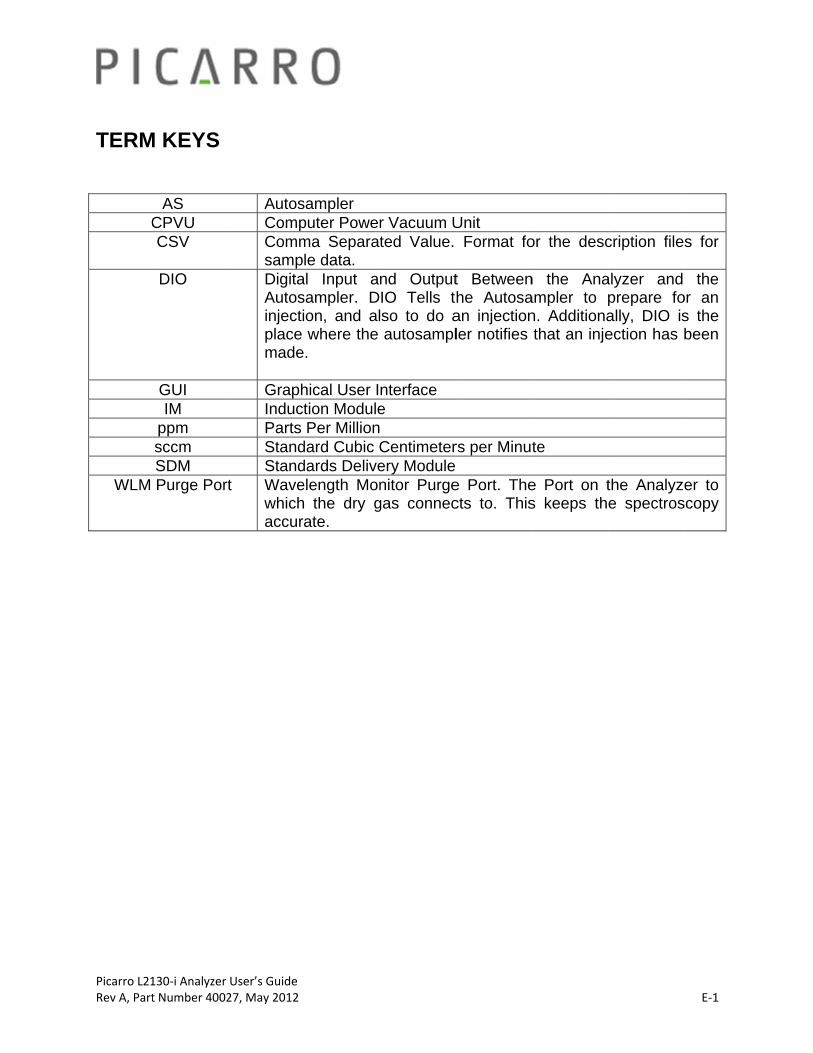
TERM
C
WLM
130‐i Analyzer t Number 4002
M KEYS
AS CPVU CSV
DIO
GUI IM
ppm sccm SDM Purge Port
User’s Guide 27, May 2012
AutosCompCommsampDigitaAutosinjectiplace made GraphInductParts StandStand
t Wavewhichaccura
sampler puter Powerma Separatle data.
al Input ansampler. Don, and alwhere the .
hical User Ition ModulePer Million
dard Cubic Cdards Deliveelength Mon the dry gate.
r Vacuum Uted Value.
nd OutputIO Tells thso to do aautosampl
nterface e Centimeterery Modulenitor Purge
gas connec
Unit Format fo
t Betweenhe Autosaan injectionler notifies
rs per Minut
e Port. Thects to. This
or the desc
n the Anaampler to pn. Additionathat an inje
te
e Port on ts keeps th
cription file
alyzer and prepare foally, DIO isection has b
the Analyzee spectros
E‐1
s for
the or an s the been
er to scopy

Picarro L2130-i Analyzer User’s Guide Rev A, Part Number 40027, May 2012 F-1
BEFORE GETTING STARTED
Examining the Shipment before Opening:
All Picarro products are thoroughly inspected and tested prior to shipment from the factory. In addition, the instruments are packed in a shipping packing system that has been specially tested and proven to be safe for most dropping. Specifically, the analyzer is packed in an inner box which is seated in foam spacers and then encased in a larger outer shell. There is ca. 3-4 inches of space between the inner and outer box which acts as a safety zone against hard shocks from drops and other mishandling reaching the analyzer.
When the analyzer is received at your site, you need to first examine the shipment. There is a ShockWatch® on the inner box, not visible from the outside, rated at 50g and usually with a red label, Figure 1 and 2.
Figure 1, 2. Outer ShockWatch®. Left, untripped, right, tripped.
If the ShockWatch® has tripped (there is red dye in the inner glass tube, see Figure 1, right hand side) DO NOT unpack the analyzer. Immediately photograph the ShockWatch® and any damage to the outside and inside packaging. E-mail the photos, along with your contact information to [email protected] and our customer support group will advise you of the next steps.
If the ShockWatch® has not been tripped, open the inner box. If the analyzer is obviously damaged, but the ShockWatch® has not been tripped, please immediately photograph the ShockWatch® and any damage to the outside and
Picarro L2130-i Analyzer User’s Guide Rev A, Part Number 40027, May 2012 F-2
inside packaging. E-mail the photos, along with your contact information to [email protected] and our customer support group will advise you of the next steps.
Even if there is extensive damage to the boxes, but no visible damage to the analyzer, you can proceed with the installation.
Checking over the Shipped Items: Depending on the system purchased, you might receive up to 6 boxes (Each box containing either the Analyzer, the External Pump for the Analyzer, the Vaporizer, the External Pump for the Vaporizer, the Autosampler, or the Standard Delivery Module.) Each of these boxes may or may not include accessories in addition to the main module that is included with each of the boxes. What is specifically included in each of these boxes will be unique for each purchase and the needs of the customer. There should be a packing list included with your shipment. Please refer to the packing list to check over that all the required items for your system have been shipped. If any of the items are missing or damaged, please contact Picarro for a replacement- [email protected] It is recommended that you keep the shipping packages, at least until the analyzer has been installed and verified as being fully operational. These shipping packages are also a very good way to ship the system to other labs or field stations, unless they will get wet. Please contact Picarro for options on transporting systems to remote labs.

Picarro L2130-i Analyzer User’s Guide Rev A, Part Number 40027, May 2012 G-1
INSTALLATION
This section describes the setup and installation of the Picarro Analyzer. Please read and understand this section thoroughly before proceeding with the installation.
WARNING: Do not attach electrical power to, or start the analyzer until after attaching and turning on the External Vacuum Pump. Do not disconnect the vacuum line while the analyzer is running. Failure to do so could result in damage to the optics.
WARNING: Picarro sells USB enabled devices, such as GPS, which are approved for use. Please do not connect USB hubs or unapproved USB devices, other than flash drives to the computer because they can interfere with the operation of the analyzer.
WARNING: If rack mounted, the Analyzer cannot support itself using a front rack mount kit alone. The instrument must be supported by a shelf or additional rails attached to the rack. A kit is available from Picarro.
CAUTION: It is imperative that the analyzer has adequate ventilation and/or cooling to maintain the ambient temperature below 35 °C when operating. Failure to provide adequate airflow, especially clearance at the front and rear panels, to ensure proper airflow and/or cooling to the analyzer will result in overheating of the analyzer causing a shutdown and potential damage. There should be 4” (10cm) of clearance in the front and back of the analyzer.
Thermal Specifications
Min Max Description
Ambient Operating Temperature
10 C 35 C Worst-case environmental limits (unless otherwise specified)
CAUTION: If the analyzer has been stored at less than 10 °C, allow the components to equalize to room temperature before starting the installation process.

Picarro L2130-i Analyzer User’s Guide Rev A, Part Number 40027, May 2012 G-2
Facility Preparation and Necessary Supplies
FACILITY PREPARATION
Space requirements: roughly 3x3 feet (0.9x0.9m)
NOTE: Take care to ensure that warm air is exhausted from any enclosure in which the analyzer is mounted.
DRY GAS SUPPLY
You will need a dry gas supply for your analyzer and vaporizer. You can purchase the pressure regulator kit #A0921 from Picarro. Please contact Picarro for more information. If you purchase a dry gas kit from Picarro, you will need the following additional supply.
1) Dry gas supply at 10-60 psi (4 bar)
Below you will find a complete part list and diagram on how to connect dry gas to the water analyzer.
1. Q1-14B-580 Air Liquide Scott Regulator 2. SS-OGM2-S2-A Swagelok Toggle Valve:

Picarro L2130-i Analyzer User’s Guide Rev A, Part Number 40027, May 2012 G-3
3. SS-T2-S-028-20 Swagelok 1/8" OD stainless steel tubing 4. SS-200-3 Swagelok 1/8" stainless steel Tee union 5. SS-400-R-2 Swagelok 1/8" (adapter fitting) to 1/4" (tube fitting) Reducing Union 6. 5033K31 McMaster-carr 1/4" OD Teflon (PTFE) tubing
Additional tools and parts are required, some others recommended. Click to download the more detailed part list and diagram. This will require you to have a Picarro community account. https://picarro.box.net/shared/static/r19c3z8etk.pdf
ADDITIONAL SUPPLIES
Included With the Instrument:
Consumables included with an autosampler are - vials, vial caps, syringe, septa, and glass wool for waste port. Additional consumables can be ordered from Picarro.
Tools included with the purchase of an analyzer are - torx drivers, screw drivers, tweezers (for vaporizer’s septa replacement), ball drivers and wrenches.
Not Included with the Instrument:
If you’ve purchased an autosampler, you may or may not need the optional
small auxiliary air pump for drying glass wool in waste port (a common fish tank air pump is commonly used) for drying the needle between injections.
If you’ve purchased an autosampler, you may or may not need the optional
solvent for cleaning the autosampler syringe: methyl-2-pyrrolidinone, anhydrous, 99.5% #328634 from Sigma-Aldrich for example is recommended. DO NOT USE ACETONE OR ALCOHOLS. Consult the MSDS for this solvent as it is potentially more harmful than alcohol solvents if mishandled.
Picarro L2130-i Analyzer User’s Guide Rev A, Part Number 40027, May 2012 G-4
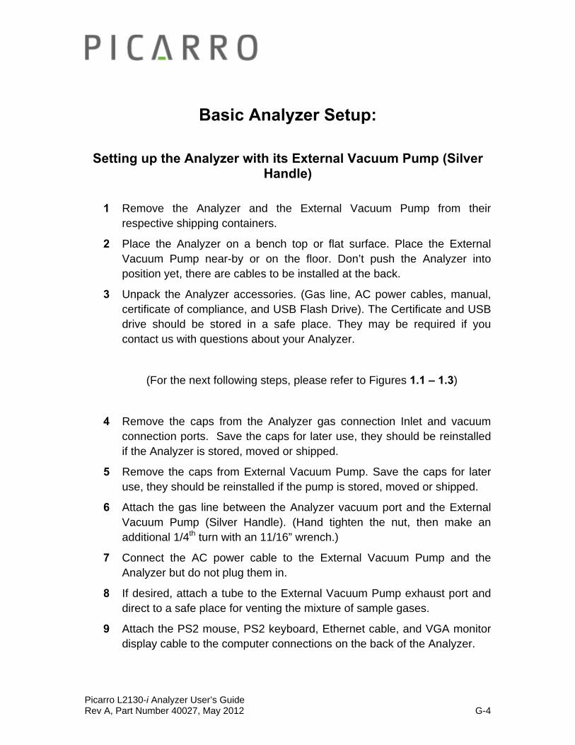
Basic Analyzer Setup:
Setting up the Analyzer with its External Vacuum Pump (Silver Handle)
1 Remove the Analyzer and the External Vacuum Pump from their respective shipping containers.
2 Place the Analyzer on a bench top or flat surface. Place the External Vacuum Pump near-by or on the floor. Don’t push the Analyzer into position yet, there are cables to be installed at the back.
3 Unpack the Analyzer accessories. (Gas line, AC power cables, manual, certificate of compliance, and USB Flash Drive). The Certificate and USB drive should be stored in a safe place. They may be required if you contact us with questions about your Analyzer.
(For the next following steps, please refer to Figures 1.1 – 1.3)
4 Remove the caps from the Analyzer gas connection Inlet and vacuum connection ports. Save the caps for later use, they should be reinstalled if the Analyzer is stored, moved or shipped.
5 Remove the caps from External Vacuum Pump. Save the caps for later use, they should be reinstalled if the pump is stored, moved or shipped.
6 Attach the gas line between the Analyzer vacuum port and the External Vacuum Pump (Silver Handle). (Hand tighten the nut, then make an additional 1/4th turn with an 11/16” wrench.)
7 Connect the AC power cable to the External Vacuum Pump and the Analyzer but do not plug them in.
8 If desired, attach a tube to the External Vacuum Pump exhaust port and direct to a safe place for venting the mixture of sample gases.
9 Attach the PS2 mouse, PS2 keyboard, Ethernet cable, and VGA monitor display cable to the computer connections on the back of the Analyzer.
Picarro L2130-i Analyzer User’s Guide Rev A, Part Number 40027, May 2012 G-5
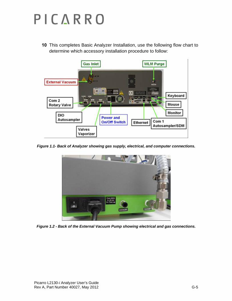
10 This completes Basic Analyzer Installation, use the following flow chart to determine which accessory installation procedure to follow:
Figure 1.1- Back of Analyzer showing gas supply, electrical, and computer connections.
Figure 1.2 - Back of the External Vacuum Pump showing electrical and gas connections.
Picarro L2130-i Analyzer User’s Guide Rev A, Part Number 40027, May 2012 G-6
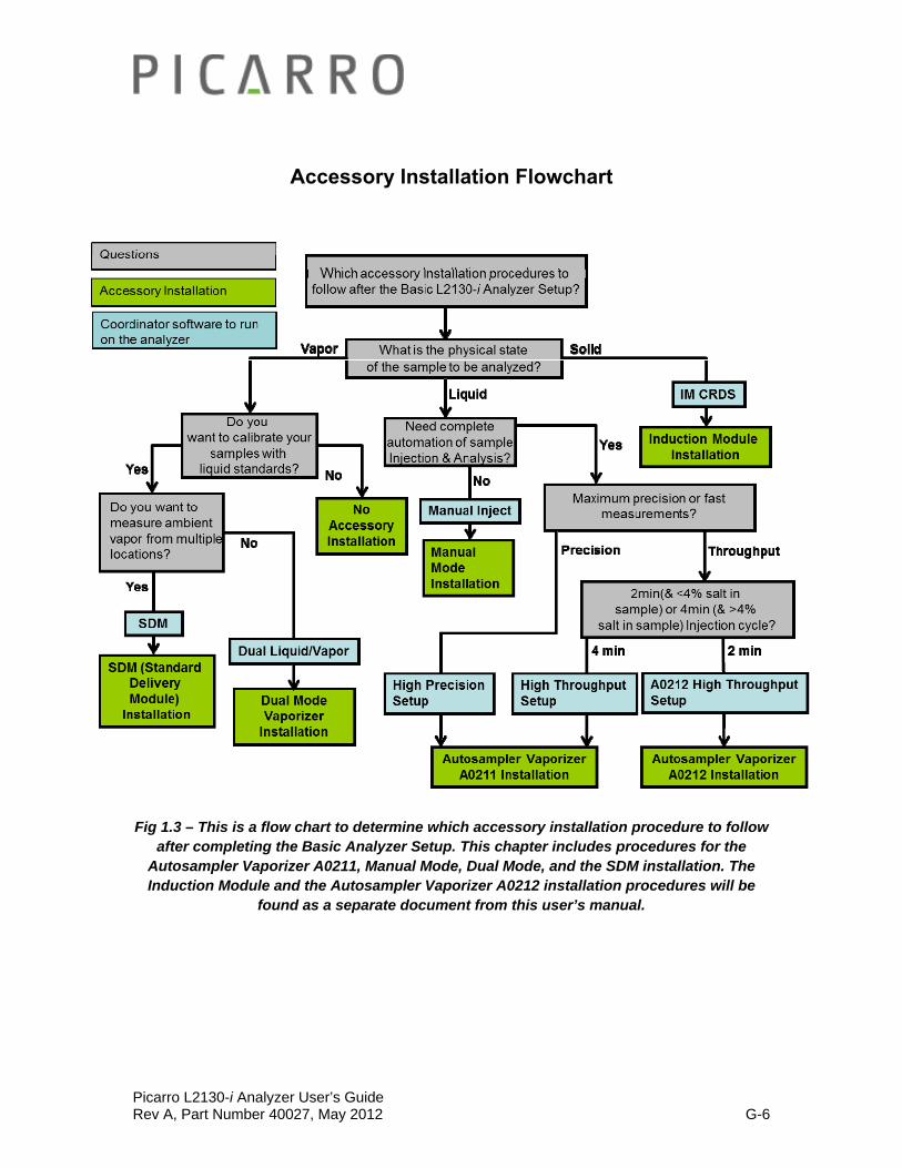
Accessory Installation Flowchart
Fig 1.3 – This is a flow chart to determine which accessory installation procedure to follow after completing the Basic Analyzer Setup. This chapter includes procedures for the
Autosampler Vaporizer A0211, Manual Mode, Dual Mode, and the SDM installation. The Induction Module and the Autosampler Vaporizer A0212 installation procedures will be
found as a separate document from this user’s manual.

Picarro L2130-i Analyzer User’s Guide Rev A, Part Number 40027, May 2012 G-7
Autosampler Vaporizer A0211 Installation: Setting up the Autosampler, the Vaporizer, and its External
Vacuum Pump after the Basic Analyzer Setup
After completing the Basic Analyzer Set Up, please follow the steps below to set up the Autosampler, the Vaporizer, and its External Vacuum Pump.
1 Connect the Autosampler vertical legs to the XY Axis Stage of the Autosampler (See Fig 2): First use the T20 Torx driver (supplied) to loosen the screw on each mounting claw on the vertical legs until it moves freely. Insert the mounting claw in the rails of the X axis unit, holding in position while tightening the screw until the claw expands and engages tightly. The distance between the legs must be 17-17 ¼” (432-438 mm) to accommodate the Picarro analyzer. Measure 1 ⅞-2” (48-51mm) from inside edge of the leg to the very outer edge of the X Axis Stage. The ribbon cable access on the XY Axis Stage and the long length of each leg should point to the front.
Figure 2 – Showing orientation and position of legs for the Autosampler.
Figure 3 - Showing the Z Axis Stage, the Torx driver and the screws.
Picarro L2130-i Analyzer User’s Guide Rev A, Part Number 40027, May 2012 G-8
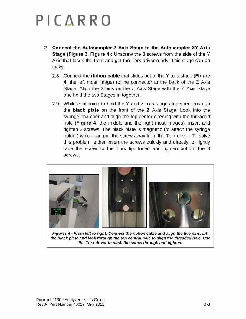
2 Connect the Autosampler Z Axis Stage to the Autosampler XY Axis Stage (Figure 3, Figure 4): Unscrew the 3 screws from the side of the Y Axis that faces the front and get the Torx driver ready. This stage can be tricky.
2.8 Connect the ribbon cable that slides out of the Y axis stage (Figure 4, the left most image) to the connector at the back of the Z Axis Stage. Align the 2 pins on the Z Axis Stage with the Y Axis Stage and hold the two Stages in together.
2.9 While continuing to hold the Y and Z axis stages together, push up the black plate on the front of the Z Axis Stage. Look into the syringe chamber and align the top center opening with the threaded hole (Figure 4, the middle and the right most images), insert and tighten 3 screws. The black plate is magnetic (to attach the syringe holder) which can pull the screw away from the Torx driver. To solve this problem, either insert the screws quickly and directly, or lightly tape the screw to the Torx tip. Insert and tighten bottom the 3 screws.
Figures 4 - From left to right: Connect the ribbon cable and align the two pins. Lift the black plate and look through the top central hole to align the threaded hole. Use
the Torx driver to push the screw through and tighten.

Picarro L2130-i Analyzer User’s Guide Rev A, Part Number 40027, May 2012 G-9
3 Attach blue syringe plate to black back plate (Figure 5, Figure 6): It attaches magnetically and is aligned by 4 pins. Make sure to install it with the black syringe lock to the left of the groove for the syringe.
Figure 5 – Left: four pins align the syringe holder. Figure 6 – Right: ensure that holder is the right way up.
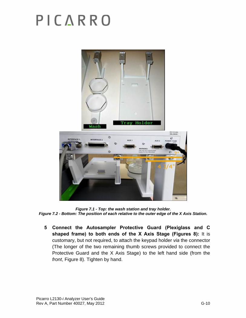
4 Connect the wash station and the tray holder to the Autosampler X Axis Stage (Figure 7.1, Figure 7.2): The inner edge of the wash station should be 4 ¾” (121 mm) from the outer edge of the X Axis Stage (not the leg). The inner edge of the tray holder arm closest to the wash station should be 7” (178 mm) from the outer edge of the X Axis Stage. The wash station is on the outside edge and furthest left (from the front), the tray holder is towards the middle.
Picarro L2130-i Analyzer User’s Guide Rev A, Part Number 40027, May 2012 G-10
Figure 7.1 - Top: the wash station and tray holder. Figure 7.2 - Bottom: The position of each relative to the outer edge of the X Axis Station.
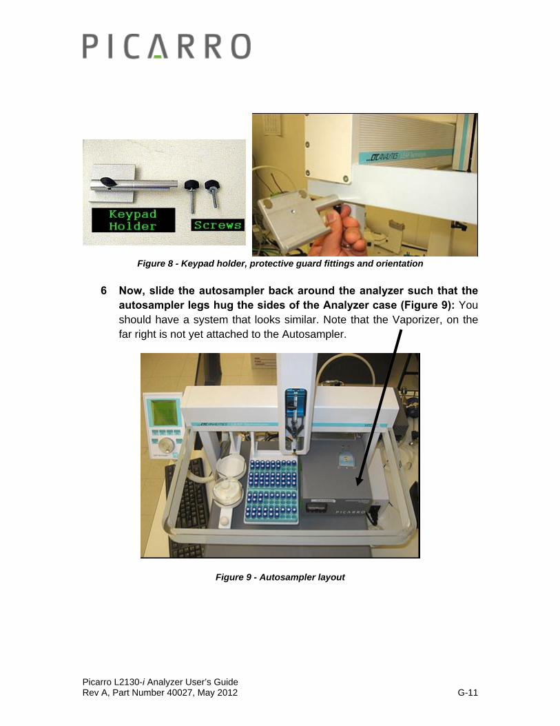
5 Connect the Autosampler Protective Guard (Plexiglass and C shaped frame) to both ends of the X Axis Stage (Figures 8): It is customary, but not required, to attach the keypad holder via the connector (The longer of the two remaining thumb screws provided to connect the Protective Guard and the X Axis Stage) to the left hand side (from the front, Figure 8). Tighten by hand.
Picarro L2130-i Analyzer User’s Guide Rev A, Part Number 40027, May 2012 G-11
Figure 8 - Keypad holder, protective guard fittings and orientation
6 Now, slide the autosampler back around the analyzer such that the autosampler legs hug the sides of the Analyzer case (Figure 9): You should have a system that looks similar. Note that the Vaporizer, on the far right is not yet attached to the Autosampler.
Figure 9 - Autosampler layout

Picarro L2130-i Analyzer User’s Guide Rev A, Part Number 40027, May 2012 G-12
• RED: Vacuum.
• GREEN: Nitrogen Connections.
• BLACK: Electrical Signals.
• BLUE: Electrical Power.
• ORANGE: Gas Transfer Line between the Analyzer and the Vaporizer.
Fig 10.1 – An Overview of the back connections for the Autosampler, the Vaporizer, the Analyzer, and the two External Pumps (not shown) Setup.
7 Make the electrical connections from the back of the Autosampler to the back of the Analyzer and a power source (Fig 10.1 – 10.2):
‘SER1’ on the Autosampler connects to female DB-9 ‘Com 1’ on the Analyzer using the beige cable.
Picarro L2130-i Analyzer User’s Guide Rev A, Part Number 40027, May 2012 G-13
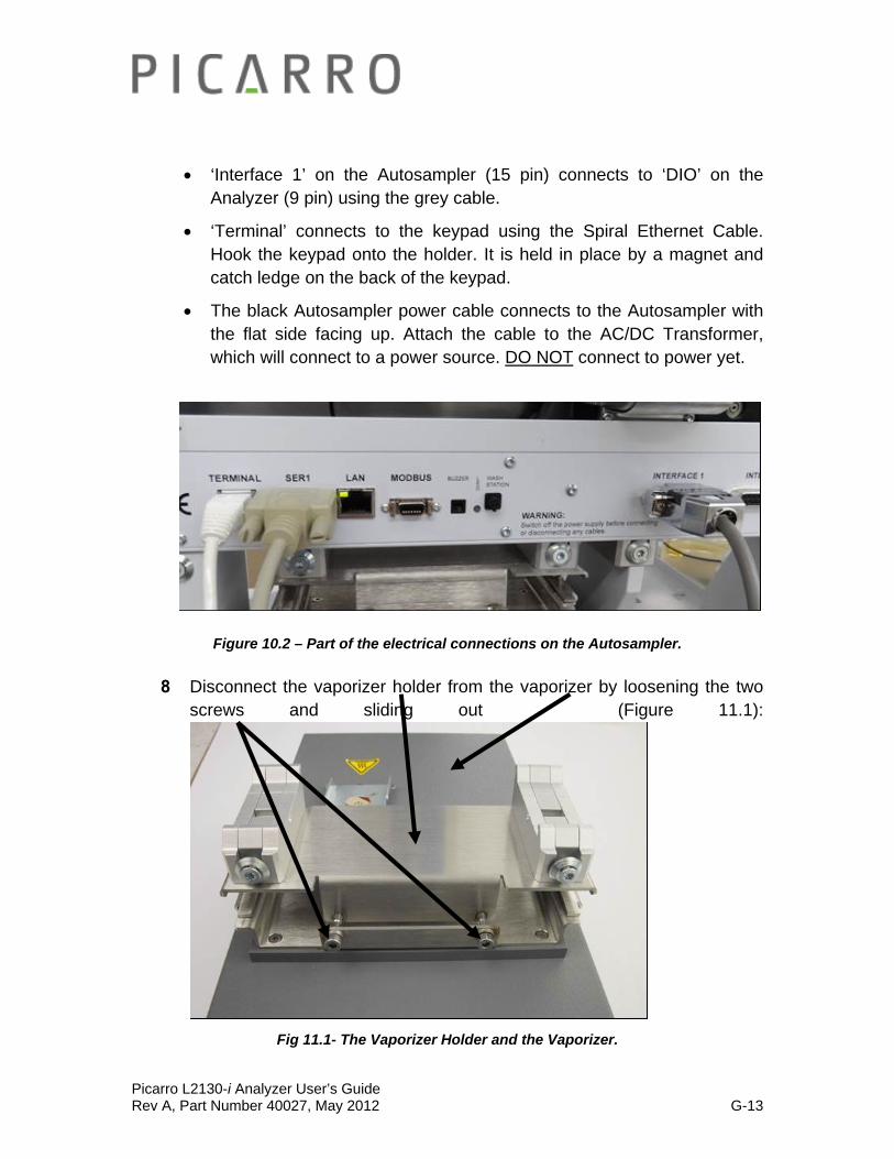
‘Interface 1’ on the Autosampler (15 pin) connects to ‘DIO’ on the Analyzer (9 pin) using the grey cable.
‘Terminal’ connects to the keypad using the Spiral Ethernet Cable. Hook the keypad onto the holder. It is held in place by a magnet and catch ledge on the back of the keypad.
The black Autosampler power cable connects to the Autosampler with the flat side facing up. Attach the cable to the AC/DC Transformer, which will connect to a power source. DO NOT connect to power yet.
Figure 10.2 – Part of the electrical connections on the Autosampler.
8 Disconnect the vaporizer holder from the vaporizer by loosening the two screws and sliding out (Figure 11.1):
Fig 11.1- The Vaporizer Holder and the Vaporizer.
Picarro L2130-i Analyzer User’s Guide Rev A, Part Number 40027, May 2012 G-14
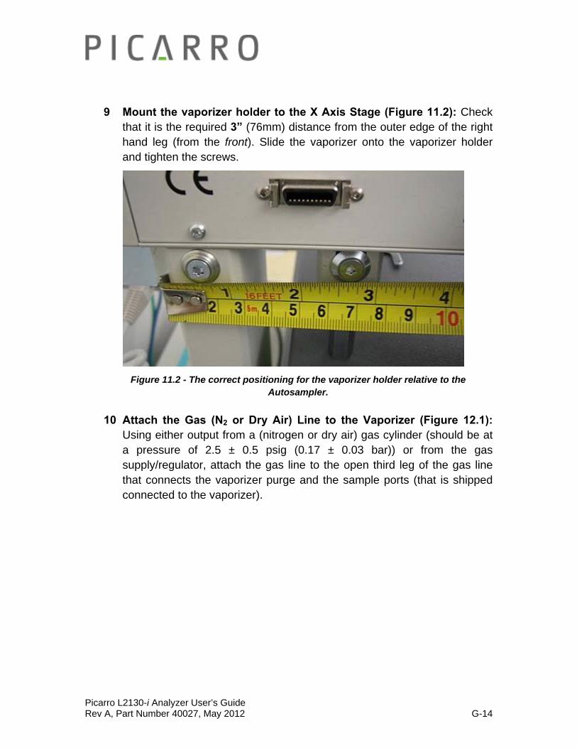
9 Mount the vaporizer holder to the X Axis Stage (Figure 11.2): Check that it is the required 3” (76mm) distance from the outer edge of the right hand leg (from the front). Slide the vaporizer onto the vaporizer holder and tighten the screws.
Figure 11.2 - The correct positioning for the vaporizer holder relative to the Autosampler.
10 Attach the Gas (N2 or Dry Air) Line to the Vaporizer (Figure 12.1): Using either output from a (nitrogen or dry air) gas cylinder (should be at a pressure of 2.5 ± 0.5 psig (0.17 ± 0.03 bar)) or from the gas supply/regulator, attach the gas line to the open third leg of the gas line that connects the vaporizer purge and the sample ports (that is shipped connected to the vaporizer).
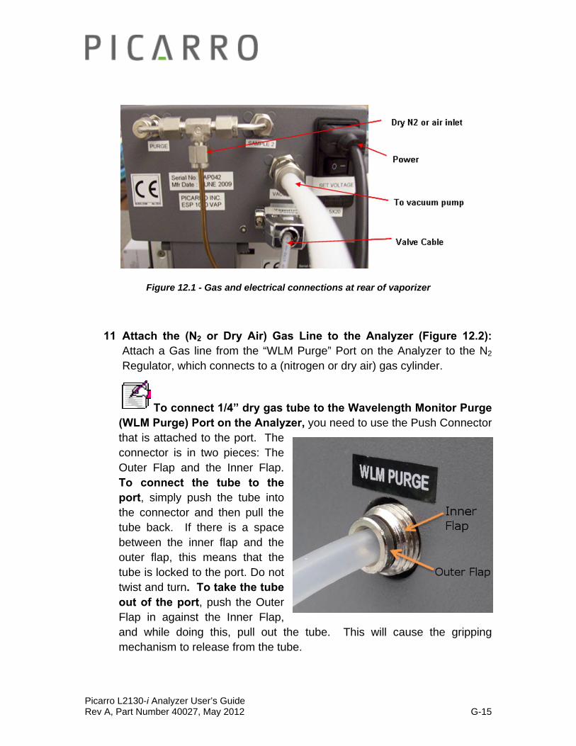
Picarro L2130-i Analyzer User’s Guide Rev A, Part Number 40027, May 2012 G-15
Figure 12.1 - Gas and electrical connections at rear of vaporizer
11 Attach the (N2 or Dry Air) Gas Line to the Analyzer (Figure 12.2): Attach a Gas line from the “WLM Purge” Port on the Analyzer to the N2 Regulator, which connects to a (nitrogen or dry air) gas cylinder.
To connect 1/4” dry gas tube to the Wavelength Monitor Purge (WLM Purge) Port on the Analyzer, you need to use the Push Connector that is attached to the port. The connector is in two pieces: The Outer Flap and the Inner Flap. To connect the tube to the port, simply push the tube into the connector and then pull the tube back. If there is a space between the inner flap and the outer flap, this means that the tube is locked to the port. Do not twist and turn. To take the tube out of the port, push the Outer Flap in against the Inner Flap, and while doing this, pull out the tube. This will cause the gripping mechanism to release from the tube.
Picarro L2130-i Analyzer User’s Guide Rev A, Part Number 40027, May 2012 G-16
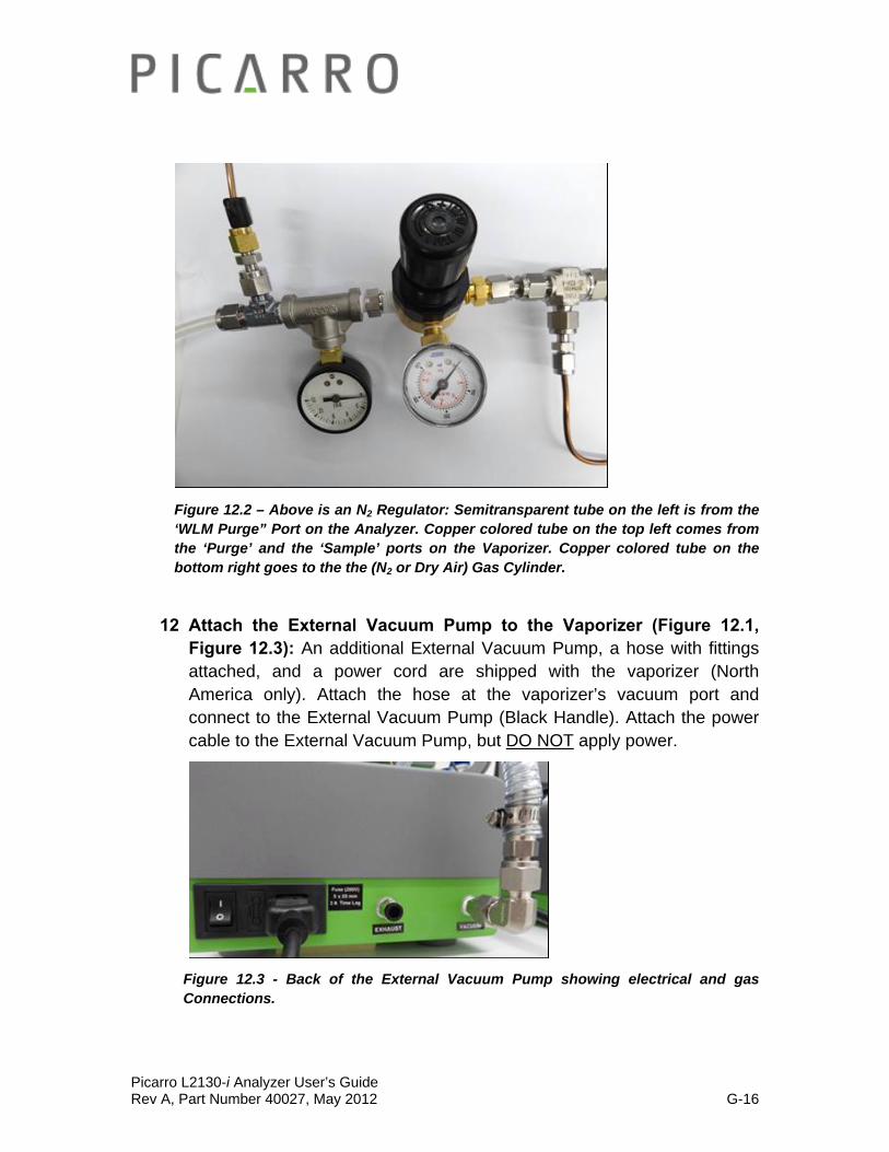
Figure 12.2 – Above is an N2 Regulator: Semitransparent tube on the left is from the ‘WLM Purge” Port on the Analyzer. Copper colored tube on the top left comes from the ‘Purge’ and the ‘Sample’ ports on the Vaporizer. Copper colored tube on the bottom right goes to the the (N2 or Dry Air) Gas Cylinder.
12 Attach the External Vacuum Pump to the Vaporizer (Figure 12.1, Figure 12.3): An additional External Vacuum Pump, a hose with fittings attached, and a power cord are shipped with the vaporizer (North America only). Attach the hose at the vaporizer’s vacuum port and connect to the External Vacuum Pump (Black Handle). Attach the power cable to the External Vacuum Pump, but DO NOT apply power.
Figure 12.3 - Back of the External Vacuum Pump showing electrical and gas Connections.
Picarro L2130-i Analyzer User’s Guide Rev A, Part Number 40027, May 2012 G-17
13 Connect the Vaporizer and the Analyzer using a Grey Cable (Figure 12.1): Attach the 15 pin end of the grey valve cable to the port labelled “Vap Valves” on the vaporizer and connect to the port labeled “Valves” on the analyzer(third connector from the left at the bottom row of the Analyzer).
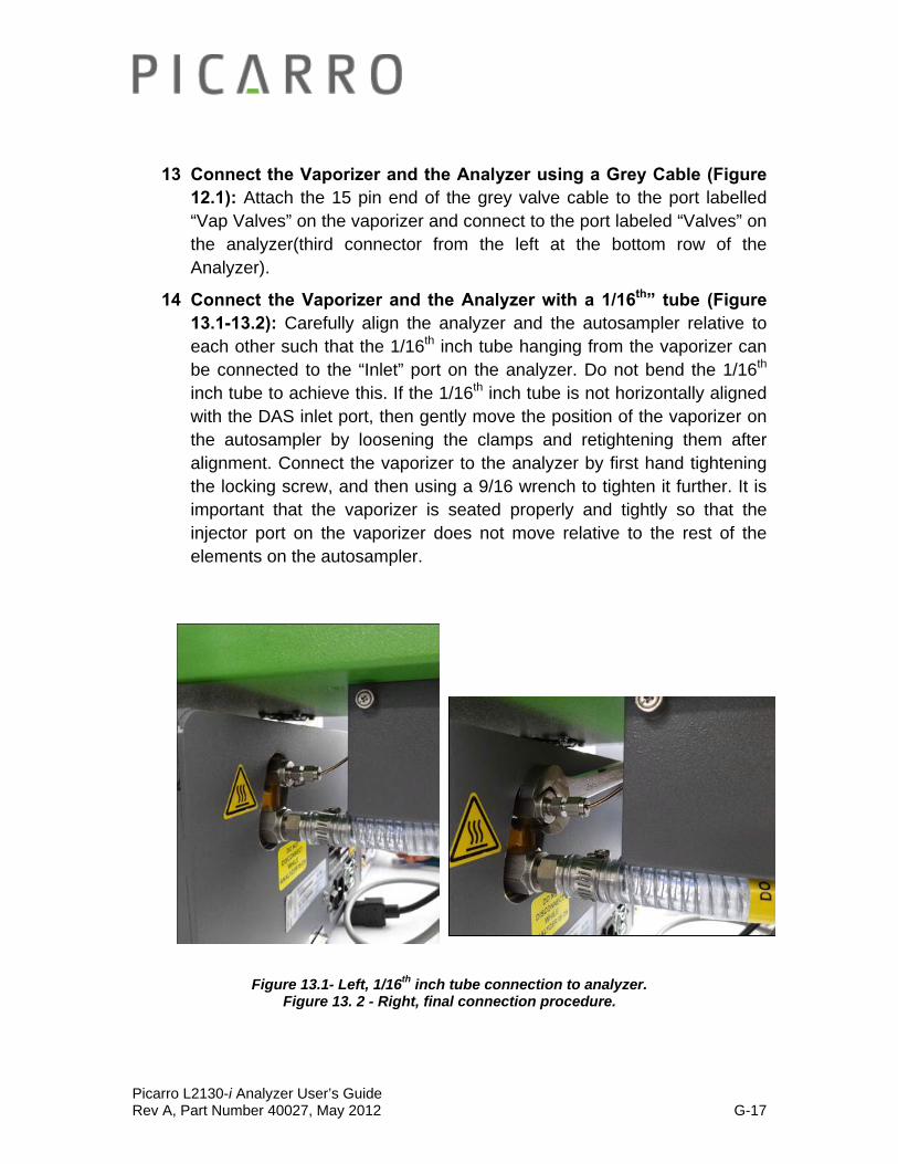
14 Connect the Vaporizer and the Analyzer with a 1/16th” tube (Figure 13.1-13.2): Carefully align the analyzer and the autosampler relative to each other such that the 1/16th inch tube hanging from the vaporizer can be connected to the “Inlet” port on the analyzer. Do not bend the 1/16th inch tube to achieve this. If the 1/16th inch tube is not horizontally aligned with the DAS inlet port, then gently move the position of the vaporizer on the autosampler by loosening the clamps and retightening them after alignment. Connect the vaporizer to the analyzer by first hand tightening the locking screw, and then using a 9/16 wrench to tighten it further. It is important that the vaporizer is seated properly and tightly so that the injector port on the vaporizer does not move relative to the rest of the elements on the autosampler.
Figure 13.1- Left, 1/16th inch tube connection to analyzer. Figure 13. 2 - Right, final connection procedure.

Picarro L2130-i Analyzer User’s Guide Rev A, Part Number 40027, May 2012 G-18
15 Check the power connections to the machines: Make sure all power cables are attached to the power outlets on the Analyzer, Vaporizer, External Vacuum Pumps, and the Autosampler Power Block. However, DO NOT connect to the power supply yet.
16 Carefully slide the complete system into position: Small movement of the components relative to one another is OK, the units are well locked. However, do not overly force the system, check for obstacles if the unit does not slide easily.
17 Power up the system: Plug in all the power cables (including the one for the monitor) into an appropriate power supply. Switch ON the components in the following order:
1. both external vacuum pumps 2. the autosampler power supply 3. the vaporizer 4. the monitor 5. the analyzer power switch (Figure 1.1) to ‘ON’
NOTE: The software to operate the instrument will start automatically after the operating system has loaded.
The user interface will appear a few seconds after the instrument software starts (see the figure on the following page).
NOTE: As the instrument is starting up, it is normal for there to be a delay in reporting data. This can take several minutes depending on how long it takes for the internal temperature to reach its operating point, and it is normal during this time for some concentration readings to be negative or constant. Additionally, the data selection pull down menus will not be populated with the appropriate items until data is actually being reported in the graph. This is typically less than 30 minutes, but depending on ambient temperature, the analyzer can take up to 2 hours to stabilize.
NOTE: Remember that for the SDM operation, the Vaporizer temperature should be set to 140 C. For all the other coordinator modes, the temperature should be set to 110 C.

Picarro L2130-i Analyzer User’s Guide Rev A, Part Number 40027, May 2012 G-19
Manual Mode Installation: Setting up the Vaporizer and its External Vacuum Pump after the
Basic Analyzer Setup
After completing the Basic Analyzer Setup (which sets up the Analyzer and its External Vacuum Pump), please follow the steps below to set up the Vaporizer and its External Vacuum Pump. This is for the manual injection option.
1 Place the Vaporizer in the correct location: Place the vaporizer on top of the analyzer using spacers of 0.5” (13 mm) thickness to set it to the appropriate height. The right edge of the vaporizer should be flush with the right edge of the analyzer (when looking from front).
2 Attach the (N2 or Dry Air) Gas line to the Vaporizer (Figure 14.1): Using either output from a (Nitrogen or Dry Air) gas cylinder (should be at a pressure of 2.5 ± 0.5 psig (0.17 ± 0.03 bar) from the gas supply/regulator, attach the gas line to the open third leg of the line that connects vaporizer purge and sample ports (that is shipped connected to the vaporizer).
Figure 14.1 – The gas and the electrical connections at the rear of the Vaporizer.
3 Attach the (N2 or Dry Air) Gas Line to the Analyzer (Figure 14.2): Attach a Gas line from the “WLM Purge” (Wavelength Monitor Purge) Port
Picarro L2130-i Analyzer User’s Guide Rev A, Part Number 40027, May 2012 G-20
on the Analyzer to the N2 Regulator, which connects to a (nitrogen or dry air) gas cylinder.
To connect 1/4” dry gas tube to the Wavelength Monitor Purge (WLM Purge) Port on the Analyzer, you need to use the Push Connector that is attached to the port. The connector is in two pieces: The Outer Flap and the Inner Flap. To connect the tube to the port, simply push the tube into the connector and then pull the tube back. If there is a space between the inner flap and the outer flap, this means that the tube is locked to the port. Do not twist and turn. To take the tube out of the port, push the Outer Flap in against the Inner Flap, and while doing this, pull out the tube. This will cause the gripping mechanism to release from the tube. See image below for further explanation.
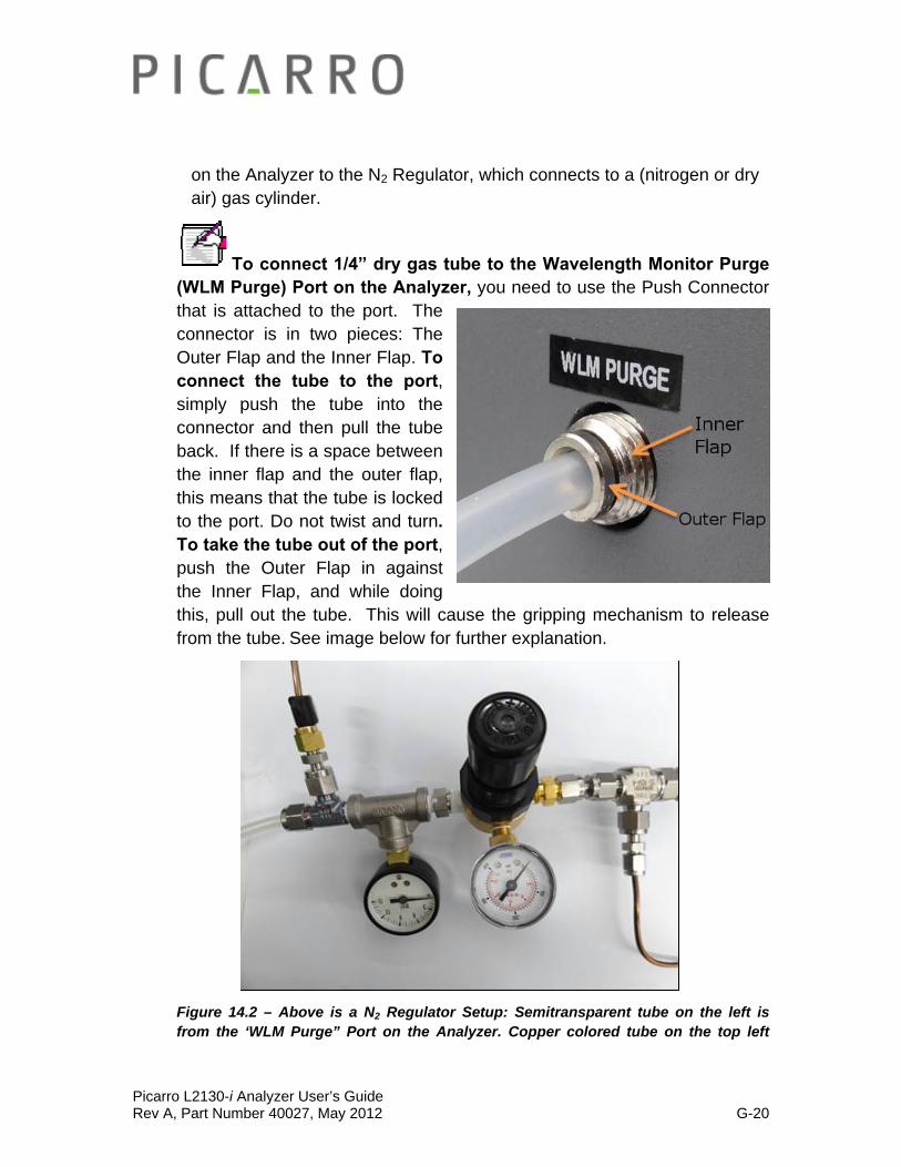
Figure 14.2 – Above is a N2 Regulator Setup: Semitransparent tube on the left is from the ‘WLM Purge” Port on the Analyzer. Copper colored tube on the top left
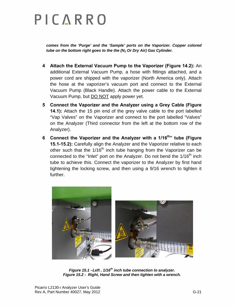
Picarro L2130-i Analyzer User’s Guide Rev A, Part Number 40027, May 2012 G-21
comes from the ‘Purge’ and the ‘Sample’ ports on the Vaporizer. Copper colored tube on the bottom right goes to the the (N2 Or Dry Air) Gas Cylinder.
4 Attach the External Vacuum Pump to the Vaporizer (Figure 14.2): An additional External Vacuum Pump, a hose with fittings attached, and a power cord are shipped with the vaporizer (North America only). Attach the hose at the vaporizer’s vacuum port and connect to the External Vacuum Pump (Black Handle). Attach the power cable to the External Vacuum Pump, but DO NOT apply power yet.
5 Connect the Vaporizer and the Analyzer using a Grey Cable (Figure 14.1): Attach the 15 pin end of the grey valve cable to the port labelled “Vap Valves” on the Vaporizer and connect to the port labelled “Valves” on the Analyzer (Third connector from the left at the bottom row of the Analyzer).
6 Connect the Vaporizer and the Analyzer with a 1/16th” tube (Figure 15.1-15.2): Carefully align the Analyzer and the Vaporizer relative to each other such that the 1/16th inch tube hanging from the Vaporizer can be connected to the “Inlet” port on the Analyzer. Do not bend the 1/16th inch tube to achieve this. Connect the vaporizer to the Analyzer by first hand tightening the locking screw, and then using a 9/16 wrench to tighten it further.
Figure 15.1 –Left , 1/16th inch tube connection to analyzer. Figure 15.2 - Right, Hand Screw and then tighten with a wrench.

Picarro L2130-i Analyzer User’s Guide Rev A, Part Number 40027, May 2012 G-22
7 Check the Power Connections to the Machines: Make sure all power cables are attached to the power outlets on the Analyzer, Vaporizer, and two External Vacuum Pumps but not yet connected to the power supply.
8 Carefully slide the complete system into position: Small movement of the components relative to one another is OK, the units are well locked. However, do not overly force the system, check for obstacles if the unit does not slide easily.
9 Power up the System: Plug all the power cables (including the one for the monitor) into an appropriate power supply. Switch ON the components in the following order
1. both External Vacuum Pumps 2. the Vaporizer 3. the monitor 4. the Analyzer power switch to ‘ON’
NOTE: The software to operate the instrument will start automatically after the operating system has loaded.
The user interface will appear a few seconds after the instrument software starts (see the figure on the following page).
NOTE: As the instrument is starting up, it is normal for there to be a delay in reporting data. This can take several minutes depending on how long it takes for the internal temperature to reach its operating point, and it is normal during this time for some concentration readings to be negative or constant. Additionally, the data selection pull down menus will not be populated with the appropriate items until data is actually being reported in the graph. This is typically less than 30 minutes, but depending on ambient temperature, the analyzer can take up to 1 hour to stabilize.
NOTE: Remember that for the SDM operation, the Vaporizer temperature should be set to 140 C. For all the other coordinator modes, the temperature should be set to 110 C.

Picarro L2130-i Analyzer User’s Guide Rev A, Part Number 40027, May 2012 G-23
Dual Mode Vaporizer Installation: Setting up the Autosampler, the Vaporizer, its additional
External Vacuum Pump, and the Dual Mode Switching Valve after the Basic Analyzer Setup
After completing the Basic Analyzer Setup, follow the procedures below to set up the Autosampler, Vaporizer (& its external Pump), and the Dual Mode Switching Valve with the existing setup.
1 Connect the Autosampler vertical legs to the XY Axis Stage of the Autosampler (See Fig 16): First use the T20 Torx driver (supplied) to loosen the screw on each mounting claw on the vertical legs until it moves freely. Insert the mounting claw in the rails of the X axis unit, holding in position while tightening the screw until the claw expands and engages tightly. The distance between the legs must be 17-17 ¼” (432-438 mm) to accommodate the Picarro analyzer. Measure 1 ⅞-2” (48-51mm) from inside edge of the leg to the very outer edge of the X Axis Stage. The ribbon cable access on the XY Axis Stage and the long length of each leg should point to the front.
Figures 16 – Showing orientation and position of legs for the Autosampler.
Picarro L2130-i Analyzer User’s Guide Rev A, Part Number 40027, May 2012 G-24
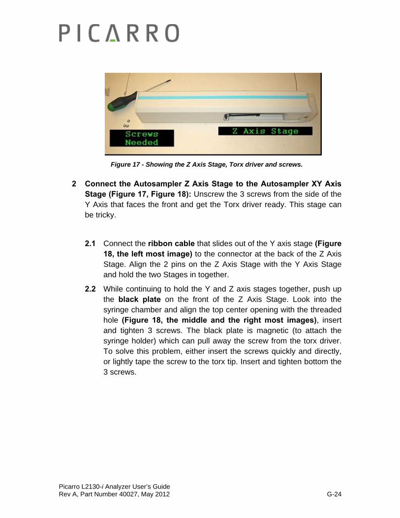
Figure 17 - Showing the Z Axis Stage, Torx driver and screws.
2 Connect the Autosampler Z Axis Stage to the Autosampler XY Axis Stage (Figure 17, Figure 18): Unscrew the 3 screws from the side of the Y Axis that faces the front and get the Torx driver ready. This stage can be tricky.
2.1 Connect the ribbon cable that slides out of the Y axis stage (Figure 18, the left most image) to the connector at the back of the Z Axis Stage. Align the 2 pins on the Z Axis Stage with the Y Axis Stage and hold the two Stages in together.
2.2 While continuing to hold the Y and Z axis stages together, push up the black plate on the front of the Z Axis Stage. Look into the syringe chamber and align the top center opening with the threaded hole (Figure 18, the middle and the right most images), insert and tighten 3 screws. The black plate is magnetic (to attach the syringe holder) which can pull away the screw from the torx driver. To solve this problem, either insert the screws quickly and directly, or lightly tape the screw to the torx tip. Insert and tighten bottom the 3 screws.

Picarro L2130-i Analyzer User’s Guide Rev A, Part Number 40027, May 2012 G-25
Figure 18 - From left to right: Connect the ribbon cable and align the two pins (left). Lift the black plate and look through the top central hole to align the threaded hole (middle).
Use the Torx driver to push the screw through and tighten (right).
3 Attach blue syringe plate to black back plate (Figure 19, Figure 20): It attaches magnetically and is aligned by 4 pins. Make sure to install it with the black syringe lock to the left of the groove for the syringe.
Figure 19 - Left, four pins align the syringe holder.
Figure 20: Right, ensure that holder is the right way up.
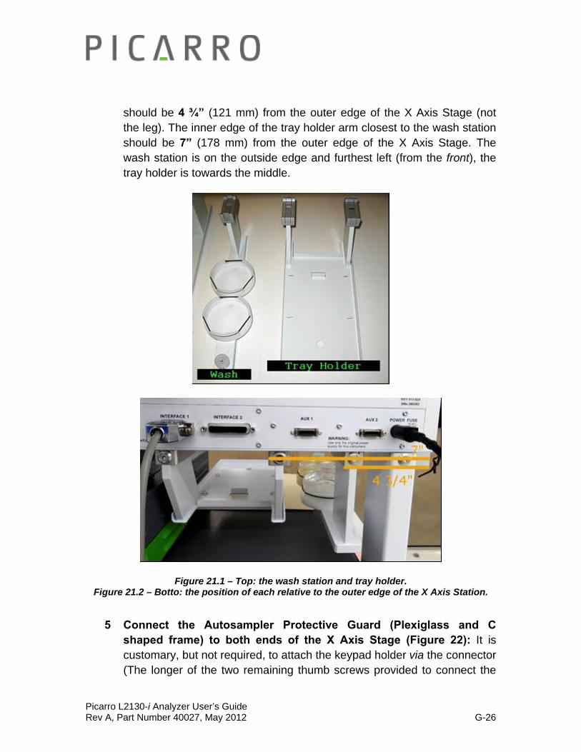
4 Connect the wash station and the tray holder to the Autosampler X Axis Stage (Figure 21.1-21.2): The inner edge of the wash station
Picarro L2130-i Analyzer User’s Guide Rev A, Part Number 40027, May 2012 G-26
should be 4 ¾” (121 mm) from the outer edge of the X Axis Stage (not the leg). The inner edge of the tray holder arm closest to the wash station should be 7” (178 mm) from the outer edge of the X Axis Stage. The wash station is on the outside edge and furthest left (from the front), the tray holder is towards the middle.
Figure 21.1 – Top: the wash station and tray holder. Figure 21.2 – Botto: the position of each relative to the outer edge of the X Axis Station.
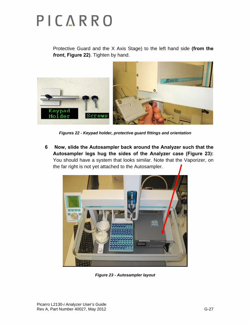
5 Connect the Autosampler Protective Guard (Plexiglass and C shaped frame) to both ends of the X Axis Stage (Figure 22): It is customary, but not required, to attach the keypad holder via the connector (The longer of the two remaining thumb screws provided to connect the
Picarro L2130-i Analyzer User’s Guide Rev A, Part Number 40027, May 2012 G-27
Protective Guard and the X Axis Stage) to the left hand side (from the front, Figure 22). Tighten by hand.
Figures 22 - Keypad holder, protective guard fittings and orientation
6 Now, slide the Autosampler back around the Analyzer such that the Autosampler legs hug the sides of the Analyzer case (Figure 23): You should have a system that looks similar. Note that the Vaporizer, on the far right is not yet attached to the Autosampler.
Figure 23 - Autosampler layout

Picarro L2130-i Analyzer User’s Guide Rev A, Part Number 40027, May 2012 G-28
• RED: Vacuum.
• GREEN: Nitrogen Connections.
• BLACK: Electrical Signals.
• BLUE: Electrical Power.
• ORANGE: Gas Transfer Line between the Analyzer and the Vaporizer.
Fig 24.1 – An Overview of the back connections for the Autosampler, the Vaporizer, the Analyzer, and the two External Pumps (not shown) Setup.
7 Make the electrical connections from the back of the Autosampler to the back of the Analyzer and a power source (Fig 24.1 – 24.2):
‘SER1’ on the Autosampler connects to female DB-9 ‘Com 1’ on the Analyzer using the beige cable.

Picarro L2130-i Analyzer User’s Guide Rev A, Part Number 40027, May 2012 G-29
‘Interface 1’ on the Autosampler (15 pin) connects to ‘DIO’ on the Analyzer (9 pin) using the grey cable.
‘Terminal’ connects to the keypad using the Spiral Ethernet Cable. Hook the keypad onto the holder. It is held in place by a magnet and catch ledge on the back of the keypad.
The black Autosampler power cable connects to the Autosampler with the flat side facing up. Attach the cable to the AC/DC Transformer, which will connect to a power source.
Figure 24.2 - Electrical connections to Analyzer
8 Disconnect the vaporizer holder from the vaporizer by loosening the two screws and sliding out. (Figure 25):
Fig 25- The Vaporizer Holder and the Vaporizer.
Picarro L2130-i Analyzer User’s Guide Rev A, Part Number 40027, May 2012 G-30
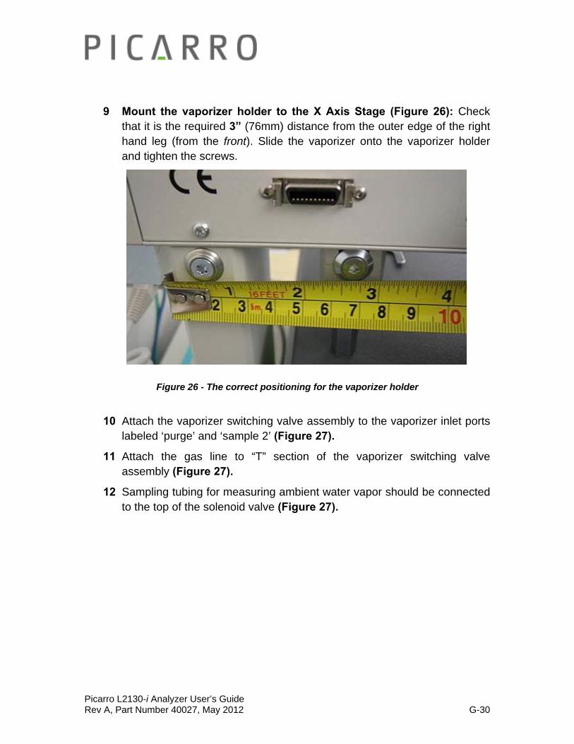
9 Mount the vaporizer holder to the X Axis Stage (Figure 26): Check that it is the required 3” (76mm) distance from the outer edge of the right hand leg (from the front). Slide the vaporizer onto the vaporizer holder and tighten the screws.
Figure 26 - The correct positioning for the vaporizer holder
10 Attach the vaporizer switching valve assembly to the vaporizer inlet ports labeled ‘purge’ and ‘sample 2’ (Figure 27).
11 Attach the gas line to “T” section of the vaporizer switching valve assembly (Figure 27).
12 Sampling tubing for measuring ambient water vapor should be connected to the top of the solenoid valve (Figure 27).

Picarro L2130-i Analyzer User’s Guide Rev A, Part Number 40027, May 2012 G-31
Figure 27 – Vaporizer Switching Valve Connected to the Vaporizer. The orange arrow signifies the direction of ambient vapour source.
13 Attach the (N2 or Dry Air) Gas Line to the Analyzer (Figure 28): Attach
a Gas line from the “WLM Purge” Port on the Analyzer to the N2 Regulator, which connects to a nitrogen gas cylinder.
To connect 1/4” dry gas tube to the Wavelength Monitor Purge (WLM Purge) Port on the Analyzer, you need to use the Push Connector that is attached to the port. The connector is in two pieces: The Outer Flap and the Inner Flap. To connect the tube to the port, simply push the tube into the connector and then pull the tube back. If there is a space between the inner flap and the outer flap, this means that the tube is
Picarro L2130-i Analyzer User’s Guide Rev A, Part Number 40027, May 2012 G-32
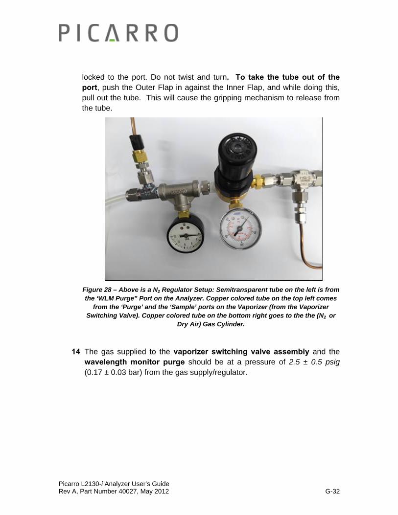
locked to the port. Do not twist and turn. To take the tube out of the port, push the Outer Flap in against the Inner Flap, and while doing this, pull out the tube. This will cause the gripping mechanism to release from the tube.
Figure 28 – Above is a N2 Regulator Setup: Semitransparent tube on the left is from the ‘WLM Purge” Port on the Analyzer. Copper colored tube on the top left comes
from the ‘Purge’ and the ‘Sample’ ports on the Vaporizer (from the Vaporizer Switching Valve). Copper colored tube on the bottom right goes to the the (N2 or
Dry Air) Gas Cylinder.
14 The gas supplied to the vaporizer switching valve assembly and the wavelength monitor purge should be at a pressure of 2.5 ± 0.5 psig (0.17 ± 0.03 bar) from the gas supply/regulator.
Picarro L2130-i Analyzer User’s Guide Rev A, Part Number 40027, May 2012 G-33
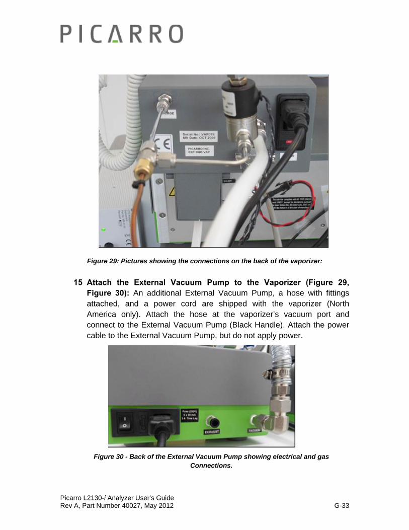
Figure 29: Pictures showing the connections on the back of the vaporizer:
15 Attach the External Vacuum Pump to the Vaporizer (Figure 29, Figure 30): An additional External Vacuum Pump, a hose with fittings attached, and a power cord are shipped with the vaporizer (North America only). Attach the hose at the vaporizer’s vacuum port and connect to the External Vacuum Pump (Black Handle). Attach the power cable to the External Vacuum Pump, but do not apply power.
Figure 30 - Back of the External Vacuum Pump showing electrical and gas Connections.
Picarro L2130-i Analyzer User’s Guide Rev A, Part Number 40027, May 2012 G-34
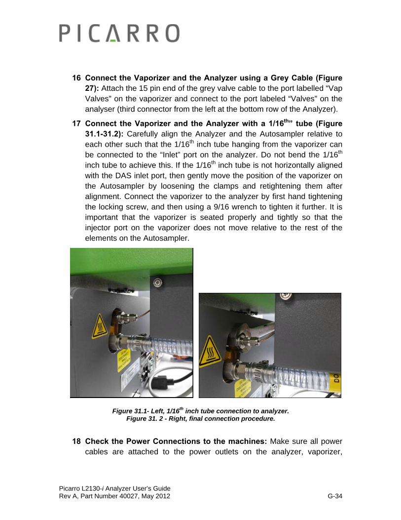
16 Connect the Vaporizer and the Analyzer using a Grey Cable (Figure 27): Attach the 15 pin end of the grey valve cable to the port labelled “Vap Valves” on the vaporizer and connect to the port labeled “Valves” on the analyser (third connector from the left at the bottom row of the Analyzer).
17 Connect the Vaporizer and the Analyzer with a 1/16th” tube (Figure 31.1-31.2): Carefully align the Analyzer and the Autosampler relative to each other such that the 1/16th inch tube hanging from the vaporizer can be connected to the “Inlet” port on the analyzer. Do not bend the 1/16th inch tube to achieve this. If the 1/16th inch tube is not horizontally aligned with the DAS inlet port, then gently move the position of the vaporizer on the Autosampler by loosening the clamps and retightening them after alignment. Connect the vaporizer to the analyzer by first hand tightening the locking screw, and then using a 9/16 wrench to tighten it further. It is important that the vaporizer is seated properly and tightly so that the injector port on the vaporizer does not move relative to the rest of the elements on the Autosampler.
Figure 31.1- Left, 1/16th inch tube connection to analyzer.
Figure 31. 2 - Right, final connection procedure.
18 Check the Power Connections to the machines: Make sure all power cables are attached to the power outlets on the analyzer, vaporizer,
Picarro L2130-i Analyzer User’s Guide Rev A, Part Number 40027, May 2012 G-35
external pumps and autosampler power block, but not yet connected to the power supply.
19 Carefully slide the complete system into position: Small movement of the components relative to one another is OK, the units are well locked. However, do not overly force the system, check for obstacles if the unit does not slide easily.
20 Power up the system: Plug in all the power cables (including the one for the monitor) into an appropriate power supply. Switch ON the components in the following order:
both external vacuum pumps
the autosampler power supply
the vaporizer
the monitor
the analyzer power switch (Figure 1) to ‘ON’
NOTE: The software to operate the instrument will start automatically after the operating system has loaded.
The user interface will appear a few seconds after the instrument software starts (see the figure on the following page).
NOTE: As the instrument is starting up, it is normal for there to be a delay in reporting data. This can take several minutes depending on how long it takes for the internal temperature to reach its operating point, and it is normal during this time for some concentration readings to be negative or constant. Additionally, the data selection pull down menus will not be populated with the appropriate items until data is actually being reported in the graph. This is typically less than 30 minutes, but depending on ambient temperature, the analyzer can take up to 1 hour to stabilize.
NOTE: Remember that for the SDM operation, the Vaporizer temperature should be set to 140 C. For all the other coordinator modes, the temperature should be set to 110 C.
Picarro L2130-i Analyzer User’s Guide Rev A, Part Number 40027, May 2012 G-36
SDM (Standards Delivery Module) Installation: Setting up the Vaporizer, its External Vacuum Pump, the SDM,
and the Drierite after following the Basic Analyzer Setup
After completing the Basic Analyzer Set Up, please follow the steps below to set up the Vaporizer, its External Vacuum, the SDM, and the Drierite.
User Supplied Components:
Dry air supplies with a moisture level of <200ppmv, 350sccm, and ambient pressure. The SDM comes with an air pump that draws in room air and supplies the correct pressure and flow when connected to a gas drying unit such as the recommended model 27070 from Drierite® Company. The recommended model holds 50 g of water and is suitable for field use. The user must supply the gas drying unit (or equivalent) along with the necessary tubing and adapters to connect the ¼” Swagelok compression style fitting at the outlet of the pump and the male 1/8” Swagelok compression style fitting at the injector assembly to the gas drying unit.
Recommend parts are:
1) SS-400-6 (1/4” Swagelok Union)
2) SS-400-6-1 (1/4” to 1/8” Swagelok Reducing Union)
3) SS-201-PC (1/8” Swagelok port connector)
4) ¼” OD Bev-A-Line IV tubing.
1 Place the Vaporizer correctly: Place the vaporizer on top of the analyzer using 4 spacers of 0.5” (13 mm) thickness to set it to the appropriate height. The right edge of the vaporizer should be flush with the right edge of the analyzer (when looking from front).
2 Connect the Analyzer and the (N2 or Dry Air) Gas Cylinder: Using either output from a (nitrogen or Dry Air)2 gas cylinder (should be at a pressure of 2.5 ± 0.5 psig (0.17 ± 0.03 bar) from a user-supplied gas supply and regulator), or the output from a Drierite tube, attach gas line to the wavelength monitor purge port (‘WLM Purge’) on the Analyzer. This step may be omitted for field studies as it is not absolutely critical but

Picarro L2130-i Analyzer User’s Guide Rev A, Part Number 40027, May 2012 G-37
it is recommended and required for testing the analyzer against specifications.
To connect 1/4” dry gas tube to the Wavelength Monitor Purge (WLM Purge) Port on the Analyzer, you need to use the Push Connector that is attached to the port. The connector is in two pieces: The Outer Flap and the Inner Flap. To connect the tube to the port, simply push the tube into the connector and then pull the tube back. If there is a space between the inner flap and the outer flap, this means that the tube is locked to the port. Do not twist and turn. To take the tube out of the port, push the Outer Flap in against the Inner Flap, and while doing this, pull out the tube. This will cause the gripping mechanism to release from the tube. See image below for further explanation.
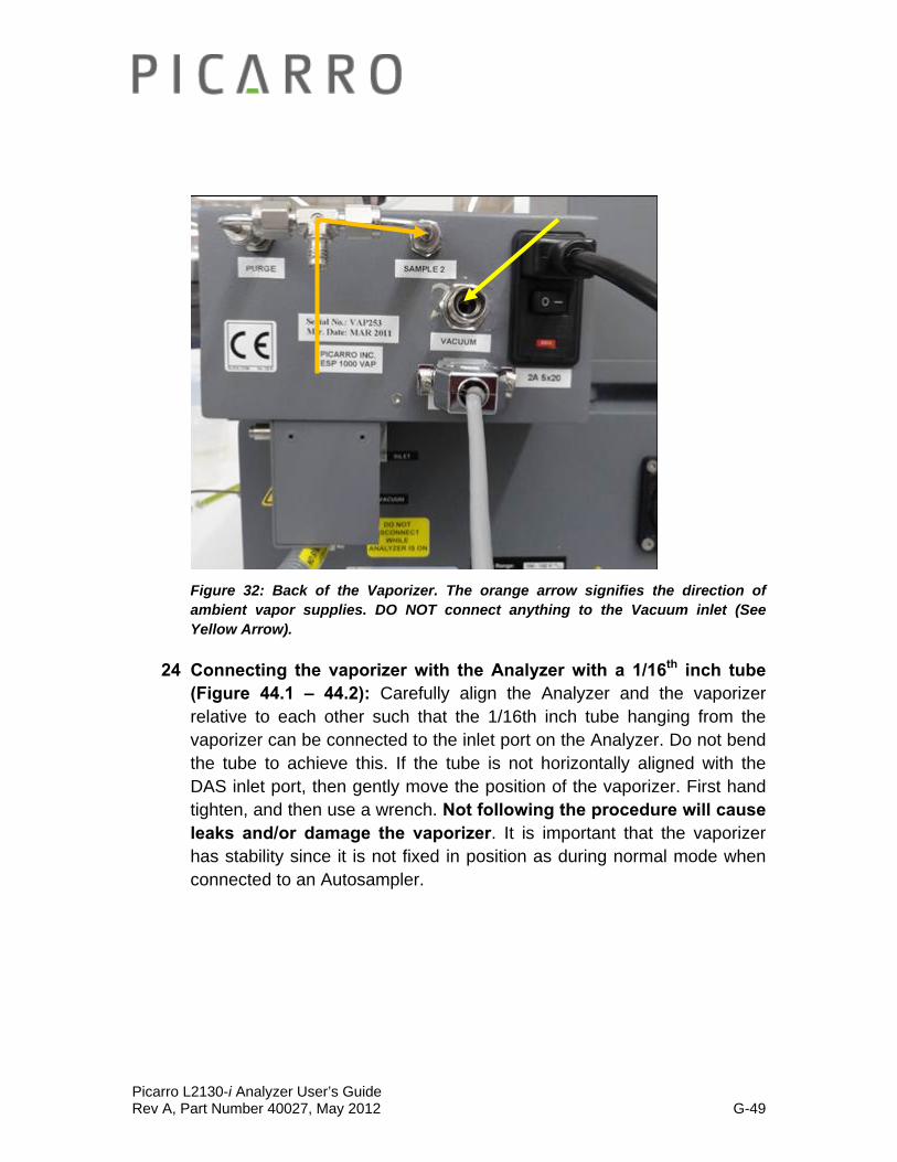
3 What to do with the ‘Purge’ Port on the Vaporizer (Figure 32): DO NOT connect anything to the port labeled “purge” on the back of the vaporizer.
4 What to do with the ‘Sample 2’ Port on the Vaporizer (Figure 32): The port labelled “sample 2” on the back of the vaporizer is where the ambient vapor is sampled from. Attach tubing with a Swagelok 1/8” connector to this port and put the open end at the desired sampling location. The image below shows a vaporizer that is sampling from the immediate air around the vaporizer. It therefore, doesn’t have a tube attached to the port labelled ‘Sample 2.’

Picarro L2130-i Analyzer User’s Guide Rev A, Part Number 40027, May 2012 G-38
Figure 32: Back of the Vaporizer. The orange arrow signifies the direction of ambient vapor supplies. DO NOT connect anything to the Vacuum inlet (See Yellow Arrow).
5 To do more than one position sampling?: If two position sampling is required then a 3 way solenoid valve should be attached to ‘sample 2’. It is controlled in the same manner as the dual liquid/vapor mode described earlier in this manual. If multi position sampling is required then “sample 2” should be connected to a multi position rotary valve.
6 What to do with the Vacuum Port (Figure 32): The port labelled “vacuum” serves as an exhaust port for excess water vapor generated during SDM calibration runs. Attach tubing with a Swagelok 3/8” connector to this port and put the open end away from and downwind of the sampling location. The image above doesn’t have a tube attached to the ‘vacuum’ port.
7 Remove SDM contents from the shipping box.
8 Place the SDM correctly: Place the main SDM unit on the top of Picarro analyzer DAS to the left of the vaporizer, front edge even with the front of the vaporizer.
Picarro L2130-i Analyzer User’s Guide Rev A, Part Number 40027, May 2012 G-39
9 Plug in the Power Cord to the back of the SDM: However, DO NOT turn ON the SDM.
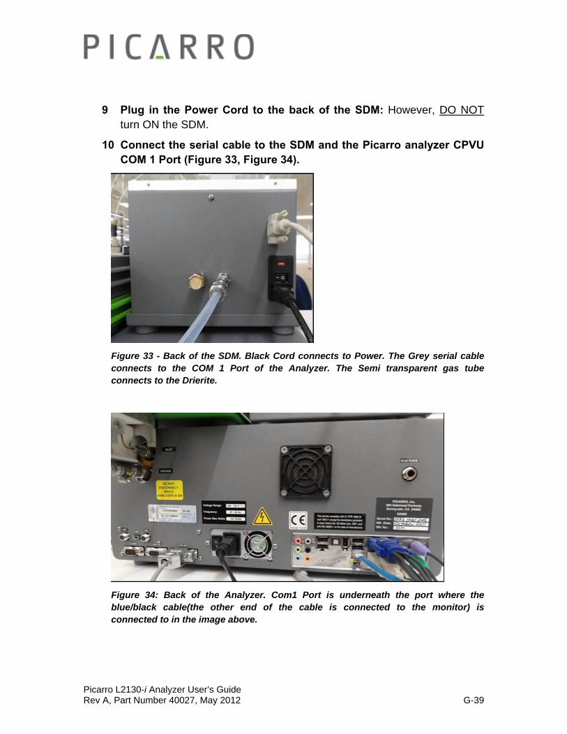
10 Connect the serial cable to the SDM and the Picarro analyzer CPVU COM 1 Port (Figure 33, Figure 34).
Figure 33 - Back of the SDM. Black Cord connects to Power. The Grey serial cable connects to the COM 1 Port of the Analyzer. The Semi transparent gas tube connects to the Drierite.
Figure 34: Back of the Analyzer. Com1 Port is underneath the port where the blue/black cable(the other end of the cable is connected to the monitor) is connected to in the image above.
Picarro L2130-i Analyzer User’s Guide Rev A, Part Number 40027, May 2012 G-40
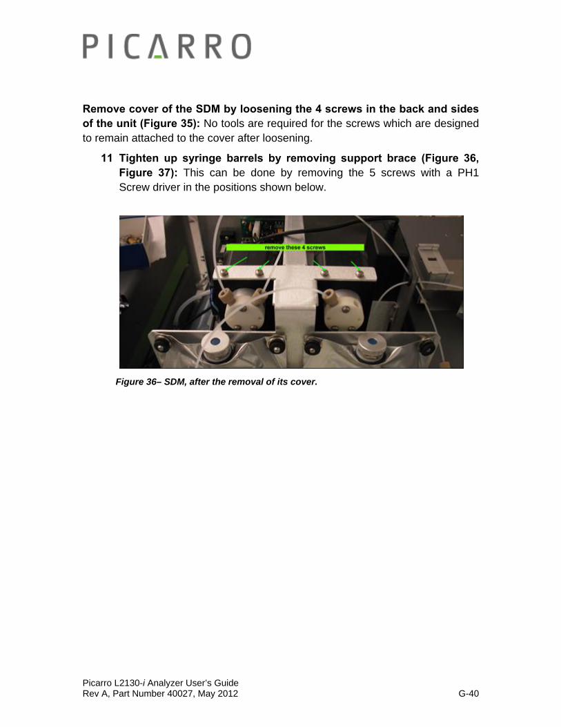
Remove cover of the SDM by loosening the 4 screws in the back and sides of the unit (Figure 35): No tools are required for the screws which are designed to remain attached to the cover after loosening.
11 Tighten up syringe barrels by removing support brace (Figure 36, Figure 37): This can be done by removing the 5 screws with a PH1 Screw driver in the positions shown below.
Figure 36– SDM, after the removal of its cover.
Picarro L2130-i Analyzer User’s Guide Rev A, Part Number 40027, May 2012 G-41
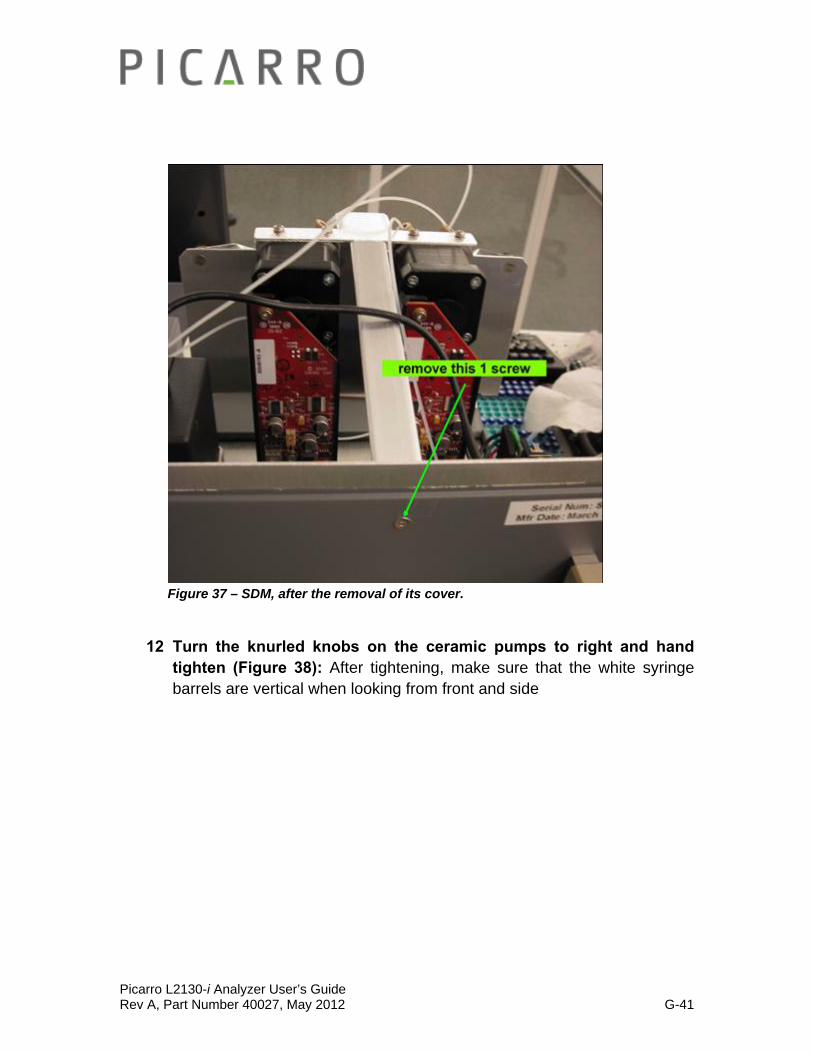
Figure 37 – SDM, after the removal of its cover.
12 Turn the knurled knobs on the ceramic pumps to right and hand tighten (Figure 38): After tightening, make sure that the white syringe barrels are vertical when looking from front and side

Picarro L2130-i Analyzer User’s Guide Rev A, Part Number 40027, May 2012 G-42
Figure 38: Turn the knurled knobs on the ceramic pumps to right and hand tighten. Notice how the tubing from the pump going to the Vaporizer leave the SDM through a small round
opening on the right wall of the SDM.
13 Connecting the tubing to the ceramic pumps (figure 38- 40):
Although the two sets of liquid tubing appear identical they have different inner diameters and should be connected as labelled. The ‘bag to pump line’ has a larger inner diameter.
Connect liquid tubing labelled “bag to pump” to the left port on both pumps (seen from the front). The ¼-28 nut with yellow ferrule attaches to the left port. Tighten snugly using your fingers. Tools are not required.
Connect liquid tubing labelled “pump to needle” to the right port on both pumps. Use the tubing segment with yellow and beige connectors. The ¼-28 nut with yellow ferrule attaches to the right port. Tighten snugly using your fingers. Tools are not required.
Picarro L2130-i Analyzer User’s Guide Rev A, Part Number 40027, May 2012 G-43
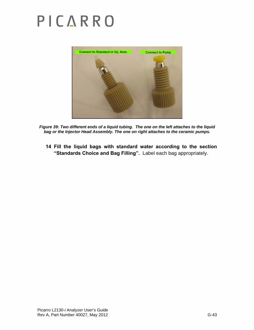
Figure 39: Two different ends of a liquid tubing. The one on the left attaches to the liquid bag or the Injector Head Assembly. The one on right attaches to the ceramic pumps.
14 Fill the liquid bags with standard water according to the section “Standards Choice and Bag Filling”. Label each bag appropriately.
Picarro L2130-i Analyzer User’s Guide Rev A, Part Number 40027, May 2012 G-44
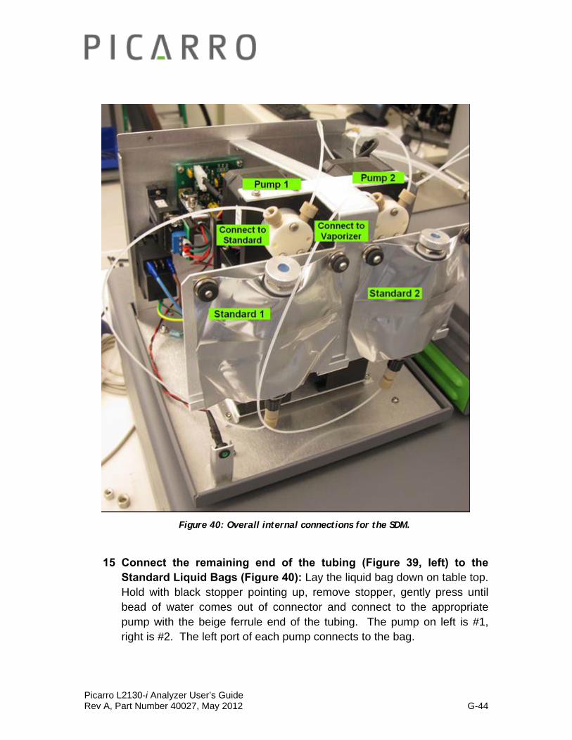
Figure 40: Overall internal connections for the SDM.
15 Connect the remaining end of the tubing (Figure 39, left) to the Standard Liquid Bags (Figure 40): Lay the liquid bag down on table top. Hold with black stopper pointing up, remove stopper, gently press until bead of water comes out of connector and connect to the appropriate pump with the beige ferrule end of the tubing. The pump on left is #1, right is #2. The left port of each pump connects to the bag.
Picarro L2130-i Analyzer User’s Guide Rev A, Part Number 40027, May 2012 G-45
16 Secure the Standard Liquid Bags (Figure 40): Hang the bag by sliding the corner holes on the bag over the posts on the SDM. Secure the bags by pressing the black grommets over the posts. Pull on bag edges and tap with finger around the bottom outlet to force any trapped air bubbles up.
17 Remove the Injector Port Cap from the Vaporizer: Remove the original Injector Port Cap (top side of the Vaporizer) and Septum from the vaporizer (Caution HOT). Screw on the lower portion of SDM injector port assembly.
18 Press and twist in upper portion of SDM injector port assembly into the lower portion: (See below for directions on how to make an Injector Port Assembly). It will gently snap into place. It is designed to rotate and should be rotated such that the desiccant output tubing puts minimal strain on it.
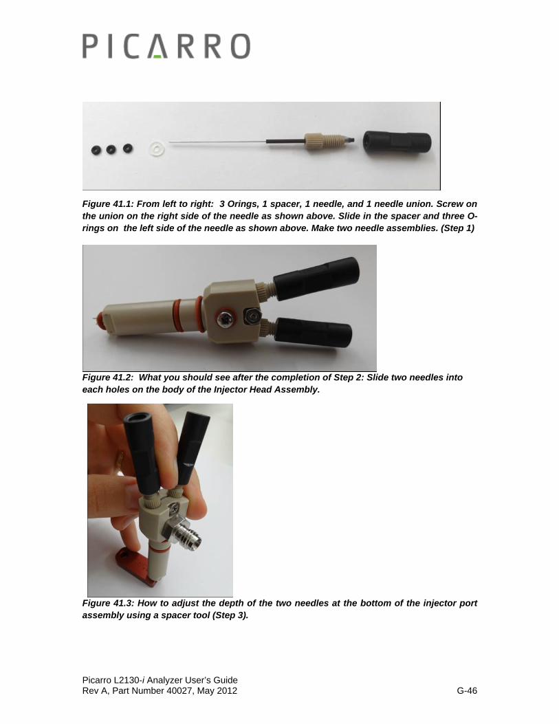
19 How to Make the SDM Injector Port Assembly:
Step 1 (Figure 41.1): Make the Needle Assembly: Hand-tighten a union on to the Needle. Slide a spacer and several O-rings onto the needle from the needle end.
Step 2 (Figure 41.2): Thread a Needle through the hole in the body of the Injector Port Assembly. Wiggle a little to get the needle in the right position. Repeat for the other hole with another needle.
Step 3 (Figure 41.3, Figure 41.4): Use the Spacer Tool to make the depth of the needle coming out of the body of the Injector Port Assembly the same. Push the needle area into the cut out of the spacer tool. Put the entire system on the ground, spacer tool at the bottom, and push down to make sure that the needles are of the same depth. Tighten the screw on the injector head assembly on top of the gas inlet. If the distance is far, adjust the spacing with additional O-rings.
Step 4 (Figure 41.5): Attach the adaptor and the elbow tube to the gas inlet of the Injector Port Assembly. First use hand to tighten the screw. Finalize with a wrench.
Step 5 (Figure 41.5): You can now place the finalized Injector Head Assembly at the opening on top of the vaporizer.
Picarro L2130-i Analyzer User’s Guide Rev A, Part Number 40027, May 2012 G-46
Figure 41.1: From left to right: 3 Orings, 1 spacer, 1 needle, and 1 needle union. Screw on the union on the right side of the needle as shown above. Slide in the spacer and three O-rings on the left side of the needle as shown above. Make two needle assemblies. (Step 1)
Figure 41.2: What you should see after the completion of Step 2: Slide two needles into each holes on the body of the Injector Head Assembly.
Figure 41.3: How to adjust the depth of the two needles at the bottom of the injector port assembly using a spacer tool (Step 3).

Picarro L2130-i Analyzer User’s Guide Rev A, Part Number 40027, May 2012 G-47
Figure 41.4: How a spacer tool is used in detail (Step 3).
Figure 41.5: SDM Injector Head Assembly after being connected to the Vaporizer. Notice how the elbow tube and the adaptor is attached to the gas inlet of the injector port assembly (Step 4, Step 5).

Picarro L2130-i Analyzer User’s Guide Rev A, Part Number 40027, May 2012 G-48
20 Connect air output of SDM to supplied ¼” tubing segment (Figure 42) with flow restrictor orifice (orifice side closest to SDM) then to desiccant canister using ¼” tubing and Swagelok compression style fittings.
21 Connect output of desiccant canister to segment of ¼” tubing (Figure 42) long enough to reach injector port of vaporizer. The end of the segment should be reduced to 1/8” male Swagelok compression style fitting.
Figure 42: SDM, User Supplied Dessicant, and the Vaporizer Setup.
22 Attach the grey valve cable at the Vaporizer (Figure 43): Connect the other end of the grey valve cable to the port labeled “valves” on the Analyzer (third connector from the left at the bottom row of the Analyzer).
23 Connect the black power cable to the vaporizer (Figure 43): DO NOT Plug the cable into a power source yet.
Picarro L2130-i Analyzer User’s Guide Rev A, Part Number 40027, May 2012 G-49
Figure 32: Back of the Vaporizer. The orange arrow signifies the direction of ambient vapor supplies. DO NOT connect anything to the Vacuum inlet (See Yellow Arrow).
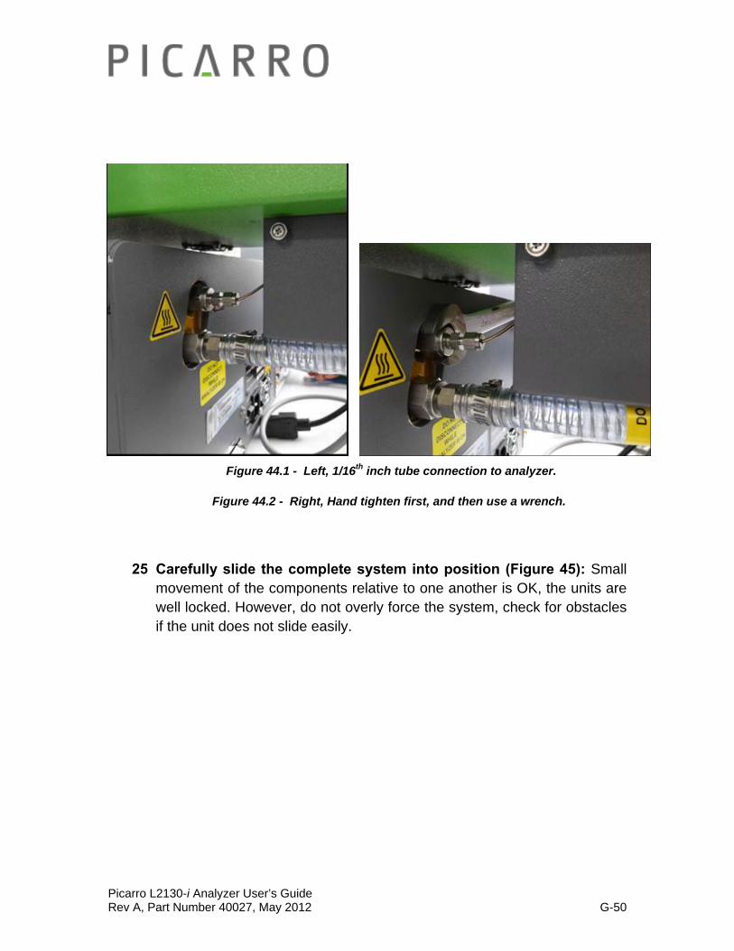
24 Connecting the vaporizer with the Analyzer with a 1/16th inch tube (Figure 44.1 – 44.2): Carefully align the Analyzer and the vaporizer relative to each other such that the 1/16th inch tube hanging from the vaporizer can be connected to the inlet port on the Analyzer. Do not bend the tube to achieve this. If the tube is not horizontally aligned with the DAS inlet port, then gently move the position of the vaporizer. First hand tighten, and then use a wrench. Not following the procedure will cause leaks and/or damage the vaporizer. It is important that the vaporizer has stability since it is not fixed in position as during normal mode when connected to an Autosampler.
Picarro L2130-i Analyzer User’s Guide Rev A, Part Number 40027, May 2012 G-50
Figure 44.1 - Left, 1/16th inch tube connection to analyzer.
Figure 44.2 - Right, Hand tighten first, and then use a wrench.
25 Carefully slide the complete system into position (Figure 45): Small movement of the components relative to one another is OK, the units are well locked. However, do not overly force the system, check for obstacles if the unit does not slide easily.
Picarro L2130-i Analyzer User’s Guide Rev A, Part Number 40027, May 2012 G-51
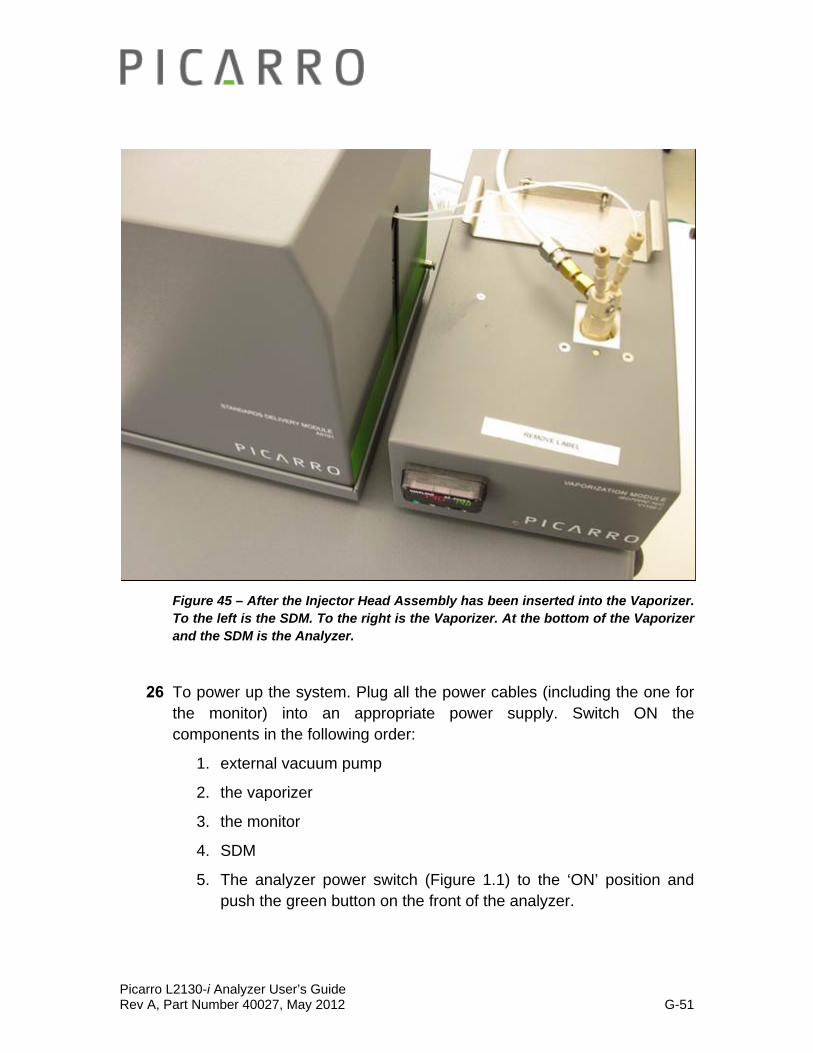
Figure 45 – After the Injector Head Assembly has been inserted into the Vaporizer. To the left is the SDM. To the right is the Vaporizer. At the bottom of the Vaporizer and the SDM is the Analyzer.
26 To power up the system. Plug all the power cables (including the one for the monitor) into an appropriate power supply. Switch ON the components in the following order:
1. external vacuum pump
2. the vaporizer
3. the monitor
4. SDM
5. The analyzer power switch (Figure 1.1) to the ‘ON’ position and push the green button on the front of the analyzer.
Picarro L2130-i Analyzer User’s Guide Rev A, Part Number 40027, May 2012 G-52
NOTE: The software to operate the instrument will start automatically after the operating system has loaded.
The user interface will appear a few seconds after the instrument software starts (see the figure on the following page).
NOTE: As the instrument is starting up, it is normal for there to be a delay in reporting data. This can take several minutes depending on how long it takes for the internal temperature to reach its operating point, and it is normal during this time for some concentration readings to be negative or constant. Additionally, the data selection pull down menus will not be populated with the appropriate items until data is actually being reported in the graph. This is typically less than 30 minutes, but depending on ambient temperature, the analyzer can take up to 1 hour to stabilize.
NOTE: Remember that for the SDM operation, the Vaporizer temperature should be set to 140 C. For all the other coordinator modes, the temperature should be set to 110 C.
Picarro L2130-i Analyzer User’s Guide Rev A, Part Number 40027, May 2012 H-1
BASIC OPERATION
SHORT OVERVIEW
The next paragraph is a generalized summary of the basic operation for systems that include the L2130-i analyzer for Isotopic H20. Please refer to the rest of the chapter and the manual for more detail. Depending on the system, it might require additional in-between steps to the ones in the paragraph below (e.g. The Standard Delivery Module Operation will require the usage of the Sequencer Software. Operations that use the Autosampler will require the usage of the Autosampler Keyboard.).
Generally, after setting up the appropriate hardware for your desired system (e.g. One autosampler operation requires the setup of the autosampler, the analyzer, the vaporizer, and the external vacuum pumps), turn on the components of the system in the order specified in the Installation section of this manual. When the analyzer is turned on, this will immediately launch the analyzer software. Afterwards, choose the coordinator mode that matches your hardware setup (e.g. High Precision mode/…), which will start the data analysis.
Picarro L2130-i Analyzer User’s Guide Rev A, Part Number 40027, May 2012 H-2
TURNING ON THE ANALYZER:
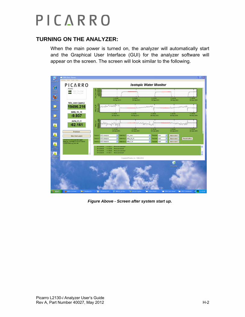
When the main power is turned on, the analyzer will automatically start and the Graphical User Interface (GUI) for the analyzer software will appear on the screen. The screen will look similar to the following.
Figure Above - Screen after system start up.

Picarro L2130-i Analyzer User’s Guide Rev A, Part Number 40027, May 2012 H-3
STARTING THE COORDINATOR
Before starting a coordinator the associated external hardware (autosampler, vaporizer, etc.) must be properly connected and turned on. Some external hardware, notably the autosampler, requires additional programming which must be performed before starting the coordinator. See autosampler section for further details.
Double click on the coordinator launcher icon. You will see the following window pop up. Select the desired coordinator from the pull down menu, and then click “Launch”.
The following coordinator window should appear on the screen.
Figure Above: Example of a Coordinator Window
Picarro L2130-i Analyzer User’s Guide Rev A, Part Number 40027, May 2012 H-4
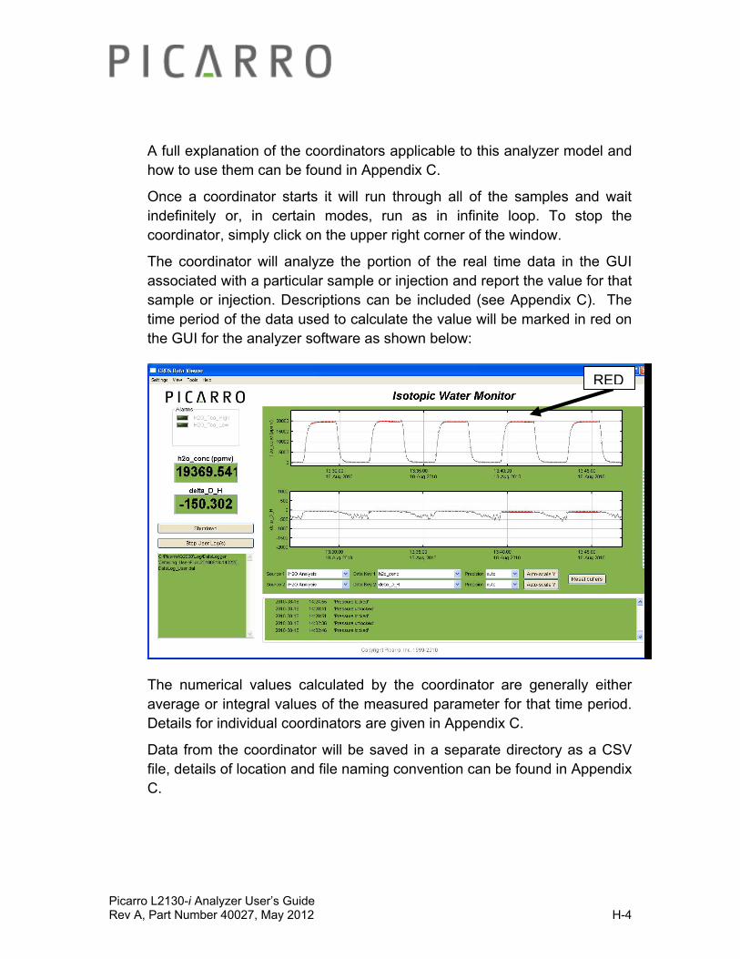
A full explanation of the coordinators applicable to this analyzer model and how to use them can be found in Appendix C.
Once a coordinator starts it will run through all of the samples and wait indefinitely or, in certain modes, run as in infinite loop. To stop the coordinator, simply click on the upper right corner of the window.
The coordinator will analyze the portion of the real time data in the GUI associated with a particular sample or injection and report the value for that sample or injection. Descriptions can be included (see Appendix C). The time period of the data used to calculate the value will be marked in red on the GUI for the analyzer software as shown below:
The numerical values calculated by the coordinator are generally either average or integral values of the measured parameter for that time period. Details for individual coordinators are given in Appendix C.
Data from the coordinator will be saved in a separate directory as a CSV file, details of location and file naming convention can be found in Appendix C.
RED
Picarro L2130-i Analyzer User’s Guide Rev A, Part Number 40027, May 2012 H-5
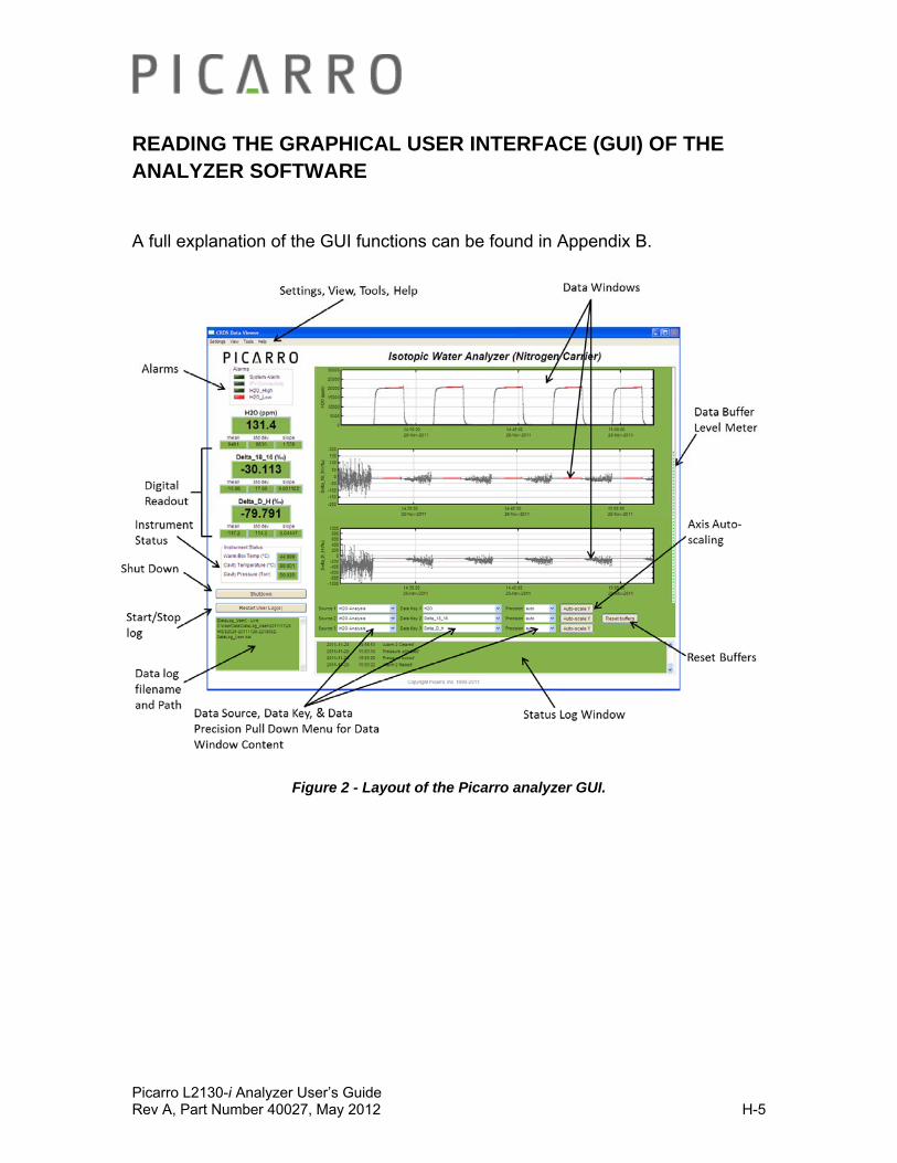
READING THE GRAPHICAL USER INTERFACE (GUI) OF THE ANALYZER SOFTWARE
A full explanation of the GUI functions can be found in Appendix B.
Figure 2 - Layout of the Picarro analyzer GUI.

Picarro L2130-i Analyzer User’s Guide Rev A, Part Number 40027, May 2012 H-6
ADJUSTING INJECTION VOLUME
(RELEVANT TO ALL EXCEPT FOR THE SDM/STANDARD DELIVERY MODULE)
For best results, liquid sample injections to the instrument should be at a concentration of 20,000±1000ppmv. Each liquid injection will be labelled as “good” in the coordinator if this concentration is between 17,000-23,000ppmv. If the concentration is significantly above/below this range (i.e. <6,500ppmv or >25,000ppmv) or if the dry background is >500ppmv, the pulse will not be analyzed and the data will not appear in the coordinator.
To achieve the appropriate injection concentration:
1) Dry nitrogen (<50ppmv water concentration) should be supplied to the instrument at 2.5±0.2psi (17.2±1.4kPa), supplied at 200sccm. If Drierite (or similar) is used for the dry air (rather than nitrogen) supply, a measured level of ~100-200ppmv will produce satisfactory data. Specifications are guaranteed only with dry nitrogen supply. Dry air can be used but will require a software change to account for the calibration shift from nitrogen. Contact Picarro for details on the software change.
2) Sample injection volume (controlled by Autosampler) should be set at ~2μL.
If the resulting concentration peak after the 2nd or 3rd liquid injection is substantially different from 20,000ppmv, the injection volume may need to be scaled appropriately: for example, if the resulting concentration peak of an initial “test” injection is 16,000ppmv, then it needs to be adjusted by the factor 20,000/16,000 = 1.25. To accomplish this, multiply the current injection volume in the Autosampler method by 1.25. Other considerations that can cause incorrect injection concentrations are bad injections (due to a clogged needle or damaged vaporizer septum) or incorrect dry gas pressure/flow restriction. For rapid optimization of injection volume use the high throughput coordinator.

Picarro L2130-i Analyzer User’s Guide Rev A, Part Number 40027, May 2012 H-7
WHERE TO FIND THE DATA
Data will be saved automatically once the analyzer starts to produce data. The data in the GUI is the continuous real time read out from the analyzer. A user relevant subset of this data is stored below.
C:\Userdata\DataLog_User \YYYY\MM\DD
Y=year, M=month, D=date.
Further details can be found under the file management section in Appendix B.
Figure Above: Window with User Data from year 2011, month 11, day 21.

Picarro L2130-i Analyzer User’s Guide Rev A, Part Number 40027, May 2012 H-8
DATA ANALYSIS OF DESCRETE SAMPLES OR OF SAMPLES FROM MULTIPLE LOCATIONS
In order to measure discrete samples (such as vaporized water injections or from individual gas bags as for isotopic measurements) or from multiple locations (when switching valves draw in ambient air from different heights) a separate software window (coordinator) is used to control the sample source and match the corresponding real time read out with the sample source.
Analyzer
GUI
Sampling
Coordinator
A B C
sample A at t=0
sample B at t=1
sample C at t=2
all data t=0 to t=3
data for A
data for B
1 2data for
C
hardware
software
data file
Figure 3 - Overview generalized schematic of Picarro analyzer system hardware, software, and data file generation.
The samples A, B, and C are introduced into the analyzer sequentially by the sampling module. The sampling module could be a set of valves, an autosampler/vaporizer combination for liquid samples, or other device. The timing of sample introduction is controlled by the coordinator software. The analyzer measures continuously and reports the data to the GUI which saves a single file where all data is reported as a function of time. The coordinator gets data from the GUI and creates a single file, the data is reported as a function of sample.
Picarro L2130-i Analyzer User’s Guide Rev A, Part Number 40027, May 2012 H-9
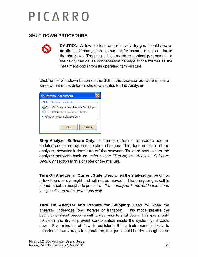
SHUT DOWN PROCEDURE
CAUTION: A flow of clean and relatively dry gas should always be directed through the instrument for several minutes prior to the shutdown. Trapping a high-moisture content gas sample in the cavity can cause condensation damage to the mirrors as the instrument cools from its operating temperature.
Clicking the Shutdown button on the GUI of the Analyzer Software opens a window that offers different shutdown states for the Analyzer.
Stop Analyzer Software Only: This mode of turn off is used to perform updates and to set up configuration changes. This does not turn off the analyzer, however it does turn off the software. To learn how to turn the analyzer software back on, refer to the “Turning the Analyzer Software Back On” section in this chapter of the manual.
Turn Off Analyzer in Current State: Used when the analyzer will be off for a few hours or overnight and will not be moved. The analyzer gas cell is stored at sub-atmospheric pressure. If the analyzer is moved in this mode it is possible to damage the gas cell!
Turn Off Analyzer and Prepare for Shipping: Used for when the analyzer undergoes long storage or transport. This mode pre-fills the cavity to ambient pressure with a gas prior to shut down. This gas should be clean and dry to prevent condensation inside the system as it cools down. Five minutes of flow is sufficient. If the instrument is likely to experience low storage temperatures, the gas should be dry enough so as

Picarro L2130-i Analyzer User’s Guide Rev A, Part Number 40027, May 2012 H-10
not to cause condensation (<1000 ppmv water concentration, for example, is sufficiently dry). If the instrument will be stored at typical room temperatures, however, the gas need not be particularly dry and the analyzer can be shut down safely after it has been purged for a few minutes with normal room air.
In Case of Electrical Power Outage
If power to the analyzer is cut-off for any reason, the analyzer will cease operation. However, when the power is reapplied, the analyzer will restart automatically, the Picarro software tools will properly close out previous files and open new files for data collection so that previously collected data, instrument diagnostics and other parameters recorded up to the time of power outage are retained.
If short power outages will be a routine operating environment, Picarro recommends use of a power conditioning and/or uninterrupted power supply that will work to prevent the more damaging operating system and software corruption problems that can occur with repeated crashes.
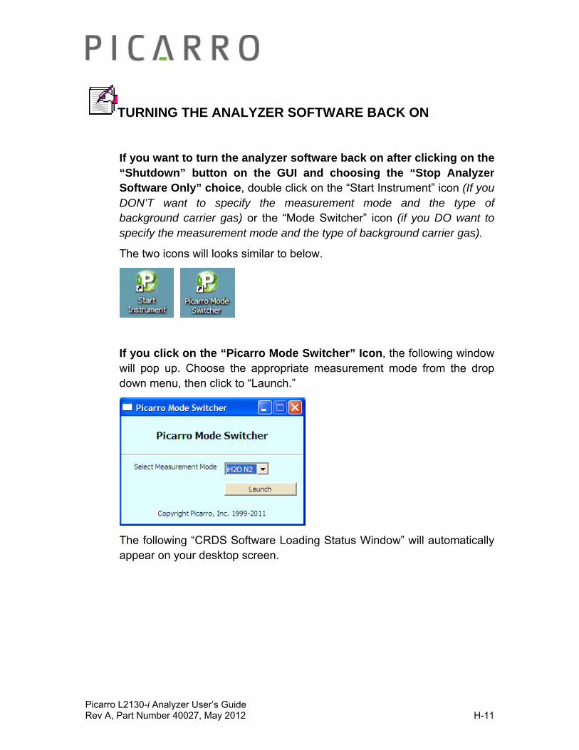
Picarro L2130-i Analyzer User’s Guide Rev A, Part Number 40027, May 2012 H-11
TURNING THE ANALYZER SOFTWARE BACK ON
If you want to turn the analyzer software back on after clicking on the “Shutdown” button on the GUI and choosing the “Stop Analyzer Software Only” choice, double click on the “Start Instrument” icon (If you DON’T want to specify the measurement mode and the type of background carrier gas) or the “Mode Switcher” icon (if you DO want to specify the measurement mode and the type of background carrier gas).
The two icons will looks similar to below.
If you click on the “Picarro Mode Switcher” Icon, the following window will pop up. Choose the appropriate measurement mode from the drop down menu, then click to “Launch.”
The following “CRDS Software Loading Status Window” will automatically appear on your desktop screen.
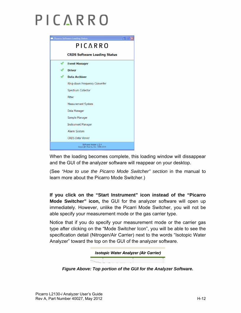
Picarro L2130-i Analyzer User’s Guide Rev A, Part Number 40027, May 2012 H-12
When the loading becomes complete, this loading window will dissappear and the GUI of the analyzer software will reappear on your desktop.
(See “How to use the Picarro Mode Switcher” section in the manual to learn more about the Picarro Mode Switcher.)
If you click on the “Start Instrument” icon instead of the “Picarro Mode Switcher” icon, the GUI for the analyzer software will open up immediately. However, unlike the Picarri Mode Switcher, you will not be able specify your measurement mode or the gas carrier type.
Notice that if you do specify your measurement mode or the carrier gas type after clicking on the “Mode Switcher Icon”, you will be able to see the specification detail (Nitrogen/Air Carrier) next to the words “Isotopic Water Analyzer” toward the top on the GUI of the analyzer software.
Figure Above: Top portion of the GUI for the Analyzer Software.

Picarro L2130-i Analyzer User’s Guide Rev A, Part Number 40027, May 2012 H-13
DESKTOP ICON EXPLANATIONS
You may/may not notice the following icons on your Analyzer desktop depending on the type of system purchased. Below are descriptions for each icons.
Instrument diagnostics and service information
Can start the Analyzer Software in a specific measurement mode (specifying background gas type). Most analyzer models are configured for one mode.
Can start the Analyzer software.
Starts the coordinator software which controls sample introduction to the analyzer. Some analyzers may not have this due to their configuration.
For post-acquisition analysis of discrete sample data generated by the coordinator.
Used to find results of Data Analysis.
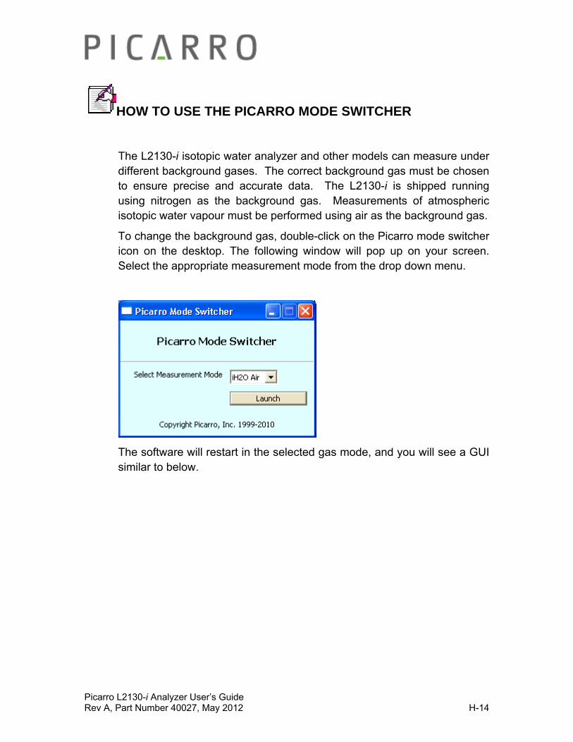
Picarro L2130-i Analyzer User’s Guide Rev A, Part Number 40027, May 2012 H-14
HOW TO USE THE PICARRO MODE SWITCHER
The L2130-i isotopic water analyzer and other models can measure under different background gases. The correct background gas must be chosen to ensure precise and accurate data. The L2130-i is shipped running using nitrogen as the background gas. Measurements of atmospheric isotopic water vapour must be performed using air as the background gas.
To change the background gas, double-click on the Picarro mode switcher icon on the desktop. The following window will pop up on your screen. Select the appropriate measurement mode from the drop down menu.
The software will restart in the selected gas mode, and you will see a GUI similar to below.
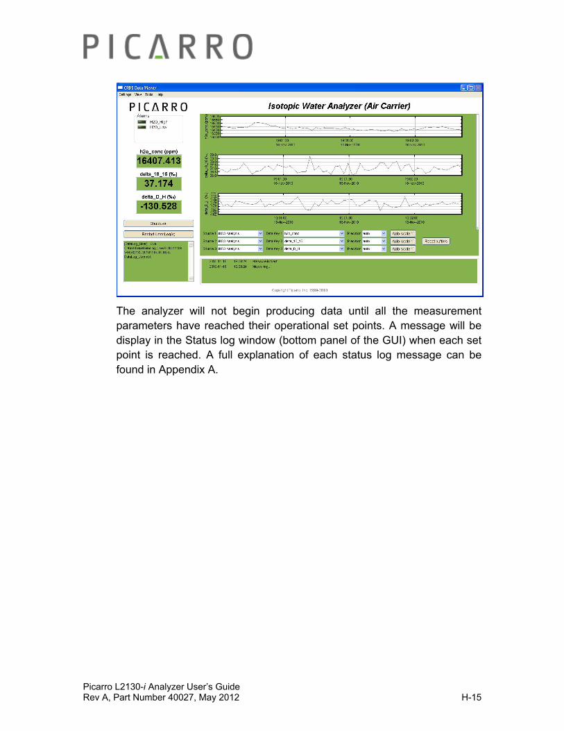
Picarro L2130-i Analyzer User’s Guide Rev A, Part Number 40027, May 2012 H-15
The analyzer will not begin producing data until all the measurement parameters have reached their operational set points. A message will be display in the Status log window (bottom panel of the GUI) when each set point is reached. A full explanation of each status log message can be found in Appendix A.
Picarro L2130-i Analyzer User’s Guide Rev A, Part Number 40027, May 2012 I-1
AUTOSAMPLER OPERATION
Introduction
The autosampler is fully described in the manual provided by the manufacturer, CTC, via Picarro. In this section we provide details on the most relevant operation with the Picarro L2130-i. Before altering methods or other modes of operation it is always wise to read this manual, the CTC manual(Pal System User Manual) – and if things don’t work as planned, contact us. Always purchase additional syringes if you plan to reprogram methods – damaged syringes caused by unexpected travel is the most common failure.
During normal operation of the analyzer the autosampler is controlled by a coordinator software running on the computer installed in the Picarro analyzer. This software coordinates sample injections with the Picarro instrument and eliminates the need for user intervention during automated multiple sample runs. However there are some one-time set up and once-per-run operations which will need to be performed directly with the autosampler keypad, these are described in this section of the documentation.
When the autosampler is running, either during manual set up or under the control of the coordinator software, the autosampler robot will move rapidly and automatically as part of its normal operations. These movements all take place within the guard rail that encloses the washes, tray holder, and injector ports. Keep yourself and all non-sample related items outside of the guard rail at all times to prevent injury or damage to the equipment.
Factory Defaults
The Picarro analyzer is delivered with a single method and job. The factory default method (named ‘Picarro’) was used to verify instrument performance specifications and is recommended for general use.
The factory default job delivers 6 injections from vial number 1 of the MT1-Rear tray provided with the instrument. The default job may be easily modified to deliver injections from all sample vials in the tray. Instructions can be found in this chapter under ‘Autosampler Jobs’.
MT1-Rear tray: The furthest back tray when standing in front of the analyzer.
MT1-Front: The closest tray when standing in front of the analyzer.
Factory default values are listed under the appropriate parameter later on in this chapter and are covered in the CTC manual (PAL System User Manual).
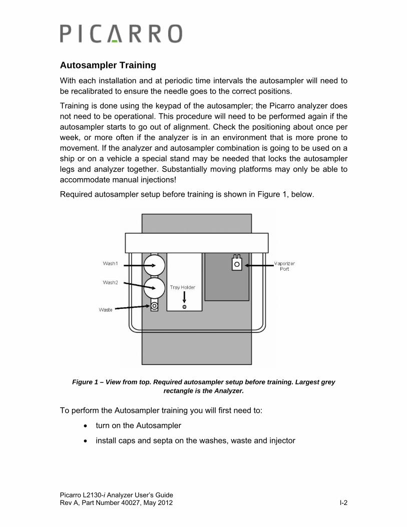
Picarro L2130-i Analyzer User’s Guide Rev A, Part Number 40027, May 2012 I-2
Autosampler Training
With each installation and at periodic time intervals the autosampler will need to be recalibrated to ensure the needle goes to the correct positions.
Training is done using the keypad of the autosampler; the Picarro analyzer does not need to be operational. This procedure will need to be performed again if the autosampler starts to go out of alignment. Check the positioning about once per week, or more often if the analyzer is in an environment that is more prone to movement. If the analyzer and autosampler combination is going to be used on a ship or on a vehicle a special stand may be needed that locks the autosampler legs and analyzer together. Substantially moving platforms may only be able to accommodate manual injections!
Required autosampler setup before training is shown in Figure 1, below.
Figure 1 – View from top. Required autosampler setup before training. Largest grey rectangle is the Analyzer.
To perform the Autosampler training you will first need to:
turn on the Autosampler
install caps and septa on the washes, waste and injector
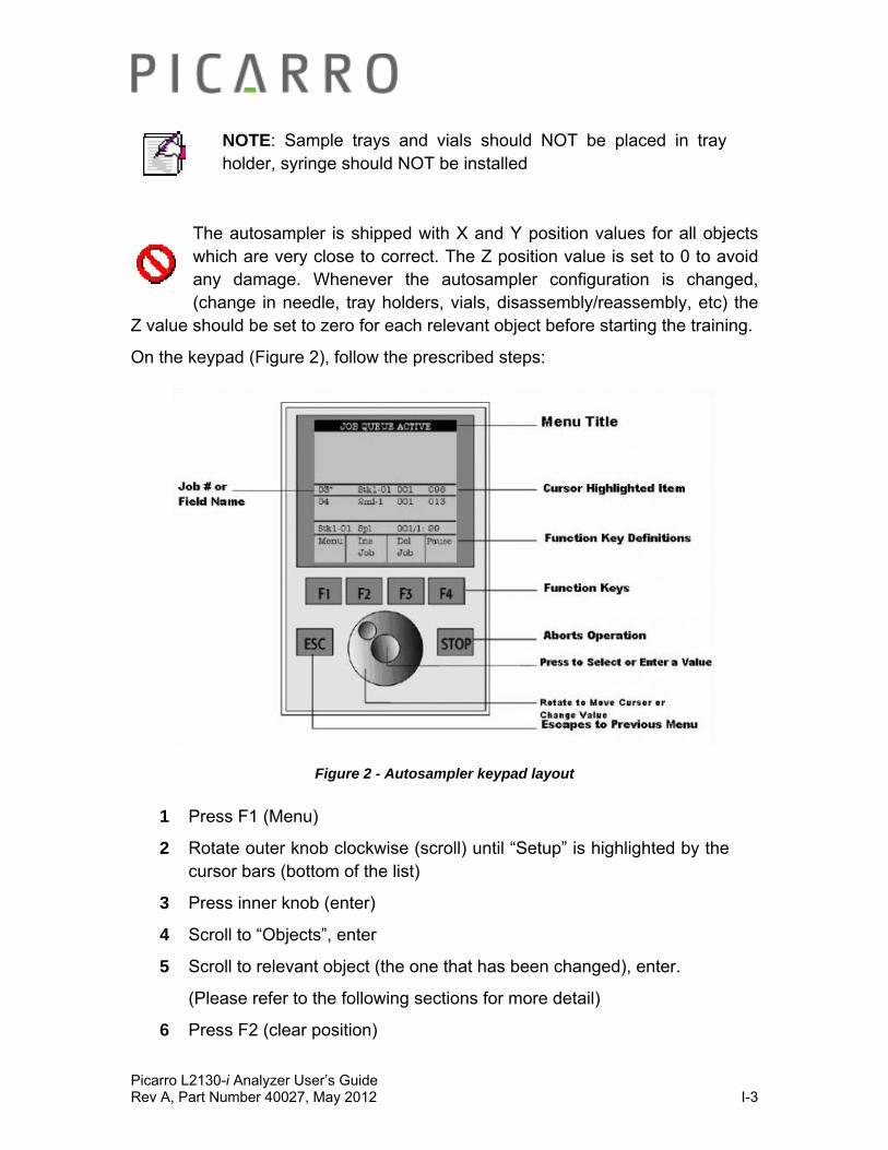
Picarro L2130-i Analyzer User’s Guide Rev A, Part Number 40027, May 2012 I-3
NOTE: Sample trays and vials should NOT be placed in tray holder, syringe should NOT be installed
The autosampler is shipped with X and Y position values for all objects which are very close to correct. The Z position value is set to 0 to avoid any damage. Whenever the autosampler configuration is changed, (change in needle, tray holders, vials, disassembly/reassembly, etc) the
Z value should be set to zero for each relevant object before starting the training.
On the keypad (Figure 2), follow the prescribed steps:
Figure 2 - Autosampler keypad layout
1 Press F1 (Menu)
2 Rotate outer knob clockwise (scroll) until “Setup” is highlighted by the cursor bars (bottom of the list)
3 Press inner knob (enter)
4 Scroll to “Objects”, enter
5 Scroll to relevant object (the one that has been changed), enter.
(Please refer to the following sections for more detail)
6 Press F2 (clear position)

Picarro L2130-i Analyzer User’s Guide Rev A, Part Number 40027, May 2012 I-4
7 Scroll to “Z”, enter. This step ensures the syringe needle guide will not accidentally hit anything.
Tray Holder Training
1 Press F1 (Menu)
2 Rotate outer knob clockwise (scroll) until “Setup” is highlighted by the cursor bars (bottom of the list)
3 Press inner knob (enter)
4 Scroll to “Objects”, enter
5 Scroll to “Tray Holders”, enter
6 Scroll to “MTH1dr1”, enter
7 Scroll to “X position”, enter
8 Now rotate outer knob until lower assembly moves to align (left-right) with hole in tray holder, enter
9 Scroll to “Y position”, enter
10 Now rotate outer knob until lower assembly moves to align (front-back) with hole in tray holder, enter
11 Scroll to “Z position”, enter
12 Now rotate outer knob until lower assembly enters the hole and is even (flush) with the bottom of the tray holder – it should be centered on the hole in the tray holder, enter. (A hint to check the depth – put a piece of paper over the hole before lowering the assembly using the scroll wheel. Gently push pull the paper until is barely moveable between the assembly and the hole
13 Press F1 (Check Position)

Picarro L2130-i Analyzer User’s Guide Rev A, Part Number 40027, May 2012 I-5
Figures Above: Align the assembly with the hole in tray holder. Make sure the bottom of the assembly is even (flush)with the bottom of the tray holder.
Autosampler will first return to the home position (moving toward the center, then back and up) and then automatically move to position the lower assembly into the hole in the tray holder.
If the Autosampler touches something before reaching the target position an error message will appear and it will ask to “retry”. You can rotate the outer knob until the “abort” option appears, then press enter. Correct the appropriate X,Y, or Z position and then check position again.
Press “ESC” button on keypad 2 times to return to main screen
Wash Station Training
1 Press F1 (Menu)
2 Rotate outer knob clockwise (scroll) until “Setup” is highlighted by the cursor bars (bottom of the list)
3 Press inner knob (enter)
4 Scroll to “Objects”, enter
5 Scroll to “Wash Stations”, enter
6 Scroll to “Wash1”, enter
Repeat steps 7-13 of previous section to train Autosampler to wash 1 (wash station in the back). The bottom assembly of the autosampler should be aligned with the wash station and just touch the top of the wash bottle. See figure below.

Picarro L2130-i Analyzer User’s Guide Rev A, Part Number 40027, May 2012 I-6
Figure Above: Bottom of assembly alighed with the wash station.
If the Autosampler touches something before reaching the target position and error message will appear and it will ask to “retry”. You can rotate the outer knob until the “abort” option appears, then press enter. Correct the appropriate X,Y, or Z position and then check position again.
Press “ESC” button on keypad 2 times to return to main screen.
Repeat for Wash2
Injector Port Training
1 Press F1 (Menu)
2 Rotate outer knob clockwise (scroll) until “Setup” is highlighted by the cursor bars (bottom of the list)
3 Press inner knob (enter)
4 Scroll to “Objects”, enter
5 Scroll to “Injectors”, enter
6 Scroll to “Vaporizer”, enter
Repeat steps 7-13 to train Autosampler to vaporizer (on top of the vaporizer unit)
For the Z position, the lower assembly should be slowly lowered down to the vaporizer port until the bottom of the syringe assembly just touches the top of the vaporizer port; enter that as the Z position. See figure below.

Picarro L2130-i Analyzer User’s Guide Rev A, Part Number 40027, May 2012 I-7
Figure Above: Bottom of assembly aligned with the injector port of vaporizer
Autosampler will first return to the home position (center, back, up) and then automatically move to the vaporizer port.
If the Autosampler touches something before reaching the target position and error message will appear and it will ask to “retry”. You can rotate the outer knob until the “abort” option appears, then press enter. Correct the appropriate X,Y, or Z position and then check position again.
Press “ESC” button on keypad 2 times to return to main screen
Waste Port Training
1 Press F1 (Menu)
2 Rotate outer knob clockwise (scroll) until “Setup” is highlighted by the cursor bars (bottom of the list)
3 Press inner knob (enter)
4 Scroll to “Objects”, enter
5 Scroll to “Injectors”, enter
6 Scroll to “Waste”, enter
Repeat steps 7-13 to train Autosampler to waste port
For the Z position the lower assembly should slowly lowered into the waste port, enter that as the Z position. The bottom assembly of the autosampler should be aligned with the waste port and just touch the top of the port. See figure below.
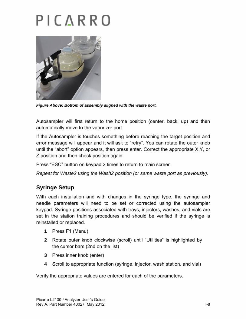
Picarro L2130-i Analyzer User’s Guide Rev A, Part Number 40027, May 2012 I-8
Figure Above: Bottom of assembly aligned with the waste port.
Autosampler will first return to the home position (center, back, up) and then automatically move to the vaporizer port.
If the Autosampler is touches something before reaching the target position and error message will appear and it will ask to “retry”. You can rotate the outer knob until the “abort” option appears, then press enter. Correct the appropriate X,Y, or Z position and then check position again.
Press “ESC” button on keypad 2 times to return to main screen
Repeat for Waste2 using the Wash2 position (or same waste port as previously).
Syringe Setup
With each installation and with changes in the syringe type, the syringe and needle parameters will need to be set or corrected using the autosampler keypad. Syringe positions associated with trays, injectors, washes, and vials are set in the station training procedures and should be verified if the syringe is reinstalled or replaced.
1 Press F1 (Menu)
2 Rotate outer knob clockwise (scroll) until “Utilities” is highlighted by the cursor bars (2nd on the list)
3 Press inner knob (enter)
4 Scroll to appropriate function (syringe, injector, wash station, and vial)
Verify the appropriate values are entered for each of the parameters.
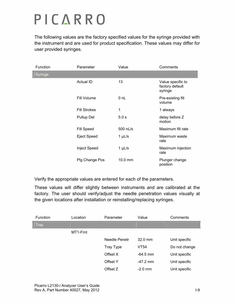
Picarro L2130-i Analyzer User’s Guide Rev A, Part Number 40027, May 2012 I-9
The following values are the factory specified values for the syringe provided with the instrument and are used for product specification. These values may differ for user provided syringes.
Function Parameter Value Comments
Syringe
Actual ID 13 Value specific to factory default syringe
Fill Volume 0 nL Pre-existing fill volume
Fill Strokes 1 1 always
Pullup Del 5.0 s delay before Z motion
Fill Speed 500 nL/s Maximum fill rate
Eject Speed 1 μL/s Maximum waste rate
Inject Speed 1 μL/s Maximum injection rate
Plg Change Pos 10.0 mm Plunger change position
Verify the appropriate values are entered for each of the parameters.
These values will differ slightly between instruments and are calibrated at the factory. The user should verify/adjust the needle penetration values visually at the given locations after installation or reinstalling/replacing syringes.
Function Location Parameter Value Comments
Tray
MT1-Frnt
Needle Penetr 32.0 mm Unit specific
Tray Type VT54 Do not change
Offset X -64.5 mm Unit specific
Offset Y -47.2 mm Unit specific
Offset Z -2.0 mm Unit specific
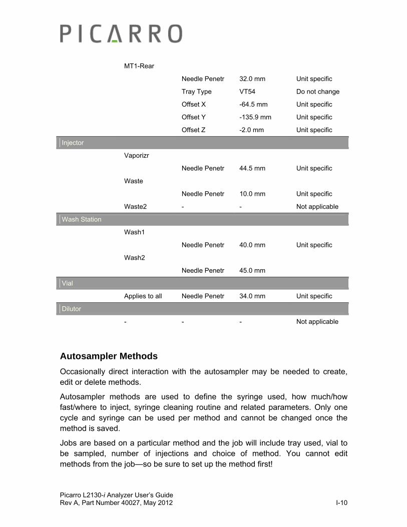
Picarro L2130-i Analyzer User’s Guide Rev A, Part Number 40027, May 2012 I-10
MT1-Rear
Needle Penetr 32.0 mm Unit specific
Tray Type VT54 Do not change
Offset X -64.5 mm Unit specific
Offset Y -135.9 mm Unit specific
Offset Z -2.0 mm Unit specific
Injector
Vaporizr
Needle Penetr 44.5 mm Unit specific
Waste
Needle Penetr 10.0 mm Unit specific
Waste2 - - Not applicable
Wash Station
Wash1
Needle Penetr 40.0 mm Unit specific
Wash2
Needle Penetr 45.0 mm
Vial
Applies to all Needle Penetr 34.0 mm Unit specific
Dilutor
- - - Not applicable
Autosampler Methods
Occasionally direct interaction with the autosampler may be needed to create, edit or delete methods.
Autosampler methods are used to define the syringe used, how much/how fast/where to inject, syringe cleaning routine and related parameters. Only one cycle and syringe can be used per method and cannot be changed once the method is saved.
Jobs are based on a particular method and the job will include tray used, vial to be sampled, number of injections and choice of method. You cannot edit methods from the job—so be sure to set up the method first!

Picarro L2130-i Analyzer User’s Guide Rev A, Part Number 40027, May 2012 I-11
Factory Supplied Methods
The Picarro is supplied with 1 method which can be used with the system in its delivered configuration or modified to create a new method. The factory supplied method was used in the instrument performance testing and should be used to verify instrument performance.
Creating a New Method
1 Press F1 (Menu)
2 Rotate outer knob clockwise (scroll) until “Methods” is highlighted by the cursor bars (bottom of the list)
3 Press inner knob (enter)
4 Press F2 “Insert Method”, enter
5 Input a method name by scrolling to desired letter, enter, repeat until name is complete. Press F4 when complete.
6 “LC-Inj” will appear, enter
7 Scroll to desired syringe, enter
8 Under “Cycle” scroll to desired value (LC-Inj, only available choice by factory default), enter.
9 Under “Syringe” scroll to desired value (factory default=5µL), enter.
10 Under “Sample Volume” scroll to desired value (factory default=1.8µL), enter. Use of a lower volume will reduce the water vapor concentration and consistency thereby affecting accuracy and precision.
11 Under “Air Volume” scroll to desired value (factory default=0nL ), enter. Air Volume is the volume aspirated after the syringe needle is moved out of the sample liquid.
12 Under “Pre Cln Slv1” scroll to desired value (factory default=0), enter. This is the number of syringe wash strokes with solvent from Wash 1.
13 Under “Pre Cln Slv2” scroll to desired value (factory default=0), enter. This is the number of syringe wash strokes with solvent from Wash 2.

Picarro L2130-i Analyzer User’s Guide Rev A, Part Number 40027, May 2012 I-12
14 Under “Pre Cln Sp1” scroll to desired value (factory default=2), enter. This is the number of times the syringe is filled with sample before the actual injection sample is pulled. These pre-cleaning samples are automatically injected into the waste port.
15 Under “Fill Speed” scroll to desired value (factory default=500nL/s), enter. This is the speed of plunger movement used to aspirate sample.
16 Under “Fill Strokes” scroll to desired value (factory default=1), enter. This is the number of filling strokes to aspirate sample.
17 Under “Pullup Del” scroll to desired value (factory default=1.0s), enter. This is the delay time between sample pull-up and ejection.
18 Under “Inject to” scroll to desired value (factory default=Vaporizr), enter. This tells the Autosampler to inject the sample into the vaporizer port.
19 Under “Inject Speed” scroll to desired value (factory default=1µL/s), enter. This is the speed of plunger movement used during sample injection.
20 Under “PreInj Del” scroll to desired value (factory default=0ms), enter. This is the delay time prior sample injection.
21 Under “PstInj Del” scroll to desired value (factory default=2.0s), enter. This is the delay time after sample injection.
22 Under “Pst Cln Slv1” scroll to desired value (factory default=0), enter. This is the number of syringe wash strokes with solvent from Wash 1 after an injection.
23 Under “Pst Cln Slv2” scroll to desired value (factory default=0), enter. This is the number of syringe wash strokes with solvent from Wash 2 after an injection.
24 Under “Vlv Cln Slv1” scroll to desired value (factory default=0), enter. This would rinse the valve inlet with solvent from Wash 1. The Autosampler as delivered is not equipped with a valve.
25 Under “Vlv Cln Slv2” scroll to desired value (factory default=0), enter. This would rinse the valve inlet with solvent from Wash 2. The Autosampler as delivered is not equipped with a valve.
Creation of a new method is now complete. Further details on any of these steps can be found in the supplied CTC manual.
Picarro L2130-i Analyzer User’s Guide Rev A, Part Number 40027, May 2012 I-13
Press “ESC” button on keypad 2 times to return to main screen
Autosampler Jobs
Direct interaction with the autosampler is needed to create, edit, start or delete jobs, change syringes, and for editing methods.
Jobs are based on a particular method and the job will include tray used, vial to be sampled, number of injections and choice of method. You cannot edit methods from the job—so be sure to set up the method first!
Factory Supplied Jobs
The Picarro L2130-i is supplied with one job which can be used with the system in its delivered configuration or modified to create a new job.
Creating a New Job
1 Load a sample tray into the tray holder, note the tray name and location.
2 Press F2 (Add Job)
3 Scroll to “Insert”, enter
4 Under “Tray” scroll to desired value (factory defaults=MT1-Rear), enter.
5 Under “First” scroll to desired value (factory default=1), enter. This means the Autosampler starts at vial position labeled number 1.
6 Under “Last” scroll to desired value (factory default=1), enter. This means the Autosampler finishes at vial position labeled number 1 (i.e. in the default configuration it only samples from vial number 1. in order to measure the entire tray choose 54, the number of the last vial)
7 Under “Increment” scroll to desired value (factory default=1), enter. This means every single vial is sampled for injection. If 2 is entered then every second vial is sampled for injection. If 3 is entered then every third vial is sampled for injection.
Picarro L2130-i Analyzer User’s Guide Rev A, Part Number 40027, May 2012 I-14
8 Under “Counts” scroll to desired value (factory default=1), enter. This means there will be 1 injection from each sample vial. Picarro recommends using 6 injections to completely eliminate memory effects.
9 Under “Methods” scroll to change method choice (factory default=Picarro), enter.
Creation of a new job is now complete. Further details on any of these steps can be found in the supplied CTC manual.
Press “ESC” button on keypad 2 times to return to main screen
Appropriate Samples and Sample Preparation
Maximum reliability of the autosampler/vaporizer/analyzer combination is ensured by removing particulates, suspended solids or other material from the same. This can be achieved by passed water samples thru a particulate filter (2-10 microns) prior to filling the sample vials or manual injection. Particulates will generally first clog the syringe needle. Although they can build up in the vaporizer, the volume of the vaporizer cell actually allows a significant number of dirty samples to be injected before cleaning is required. However, if you are injecting samples that repeatedly cause the syringe to require cleaning, the vaporizer should be visually checked (remove the septa and look for build up on the inside). The vaporizer can be cleaned by rinsing with water, contact Picarro for the vaporizer cleaning procedure and software.
Samples containing dissolved ionic solids (aka salts) can generally be injected into the vaporizer. A rinse step after each injection is recommended to prevent syringe needle clogging—in the case of high salt concentration (>5%) the use of a larger syringe (10 microliter) will significantly extend syringe lifetime. Salts will build up in the vaporizer, these can be washed out using the vaporizer cleaning procedure if they do not decompose in the vaporizer and they are sufficiently water soluble at room temperature.
Caution must be used when analyzing water samples containing organic compounds. Depending upon the nature of the organic it may build up a permanent layer inside the vaporizer which cannot be removed. Samples contain particulates, such as fruit juice, should be filtered (an in
line polypropylene Luer lock filter disk can be attached to a large syringe and used to fill the autosampler vials). Certain compounds (generally the lower
Picarro L2130-i Analyzer User’s Guide Rev A, Part Number 40027, May 2012 I-15
molecular weight compounds) interfere with the spectroscopic measurement and affect the measured isotopic ratios. The ChemCorrect software package detects and flags these situations. See Appendix E for operational details. Many organic compounds can be removed by sample pre-treatment, however some types of pre-treatment cause isotopic fractionation thus control experiments with the specific method chosen should be performed. Due to the broad range of organics and types of interactions Picarro cannot assume responsibility for measurements made using or damage caused by organic compounds.
Starting the Autosampler
For each run a job will need to be started from the Autosampler keypad. This is described in the ‘Starting the Autosampler’ section.
Overview
To run the Autosampler a job must be queued, and that that will be based on a predefined method. The loaded sample tray must be placed in the tray holder, wash solvent(s) and a syringe should also be in place.
This procedure assumes the factory default job and method or a verified user created method and job have been used and the Autosampler has been properly installed and connected to the Picarro analyzer.
Preparing the Autosampler
1 Place the loaded sample tray into the tray holder and note the location (front or rear). The sample vials hold 2mL of sample, fill with a minimum of 200µL (more is recommended to minimize isotopic fractionation due to vapor equilibrium). Ensure caps are screwed on properly (see Autosampler Maintenance for example).
2 Verify the syringe is installed.
3 Fill Wash 1 with wash solvent (factory recommendation is 1-methyl-2-pyrrolidinone (NMP) which helps prolong syringe life)
4 Place fresh glass wool or new septa in the waste port. These should be replaced every 300 injections (at same time as injector port septa). See Autosampler Maintenance for instructions on this procedure and for a discussion of the pros/cons of using glass wool or a septa.
5 Place a new septa in the vaporizer injector port. The septa should be replaced every 200-300 injections. See Autosampler Maintenance for instructions on this procedure.
Picarro L2130-i Analyzer User’s Guide Rev A, Part Number 40027, May 2012 I-16
Starting a Job
1 Verify the Picarro GUI shows the instrument is taking measurements
2 Start the Coordinator Launcher by double clicking on the desktop icon. Select the desired coordinator from the drop down menu.
3 On the Autosampler keypad press the “start” key.
4 Under “Select Job(s) to Process” select all or selected (you must scroll to desired job), enter
5 the Autosampler will move the syringe to the zero position
6 the Autosampler will now wait for a start command from the Picarro coordinator software
Do not start the ‘Coordinator’ before the instrument starts showing measurements on the GUI.
After the job queue is finished, the Autosampler will stop, and the analyzer will continue to wait for a new sample injection. At this point, the user can start a new job on the Autosampler and click on ‘New output file’ button on the CRDS Coordinator window. The user can append more
data to the same output file by simply starting a new job queue without pressing the “New output file” button.
Autosampler Maintenance
The Autosampler requires daily maintenance for reliable operation. The various procedures are described in the ‘Autosampler Maintenance’ section.
Overview
The Autosampler requires daily maintenance to ensure proper operation. Many of the consumable parts need to be replaced on a daily basis if full sample trays are run. To ensure uninterrupted operation a minimum of a week’s supply of consumables should be kept on reserve.
The consumables and how to replace them is described in the following subsections.

Picarro L2130-i Analyzer User’s Guide Rev A, Part Number 40027, May 2012 I-17
Changing Injector Port Septa
The injector port septa should be replaced every 200-300 injections. The more closely grouped needle piercing on the septa, the earlier the septa will need to be replaced. If the septum is not changed, it will be difficult to maintain the vacuum inside the vaporizer which will degrade the quality of the data.
1 To change the vaporizer injection port septum when an autosampler job is running (i.e. actively injecting samples), press the “change injector septum” button on the coordinator software. The analyzer will fill the vaporizer with dry gas. If the autosampler is not running a job then proceed directly to step 3. If no job is running and the “change injector septum” button is pressed the coordinator software will wait indefinitely (to resolve this either start a job on the autosampler or manually end the coordinator software).
2 Wait for the software indication to change the septum.
3 Remove the protective metal cover around the injection port (ensure that the insulation foam stays attached to the cover).
4 Unscrew the cap of the port.
Warning: the bottom of the cap is very hot!
5 The old septum will usually stick to the port, but if it is in the cap, remove it using tweezers (again the port and cap are really hot!).
6 Insert a new septum into the cap and screw the cap onto the port by hand until it comes to a hard stop. It should be finger tight only.

Picarro L2130-i Analyzer User’s Guide Rev A, Part Number 40027, May 2012 I-18
Caution: do not overtighten or use a wrench, the injector port will be damaged. Replace the metal cover around the injector port.
7 Press “continue” on the user interface; the analyzer will restart the vaporizer purge cycle and then wait for the next sample injection.
A septa can be replaced at any time. If a job queue is in progress, the analyzer will wait until the current sample measurement is complete (potentially as long as the cycle time) before preparing to change the septum.
Additional injector port septa can be purchased by ordering the part number “Picarro 01IPS” which is a single package contains 100 units of 9.5 mm septa.
Waste Port Septa and Glass wool
The waste port can have one of two configurations.
Configuration 1
Waste port is sealed with a septa and attached to a vacuum pump (not included). This configuration requires additional hardware and there have been reports of septa material clogging the syringe needle.
The waste port septa should be replaced every 200-300 injections, at the same time as changing the injector port. The following procedure assumes this is done at the same time as the injector port septa.
1 Pull up on cap by hand to remove from waste port. Press up from the bottom if the cap does move easily.
2 Use tweezers to remove the old septa.
3 Place the new septa into the cap and replace the cap
Additional waste port septa can be purchased by ordering the part number “Picarro 01WPS” which is a single package contains 20 units of red PTFE septa.
Configuration 2
Waste port is filled with glass wool and a small positive pressure pump (such as an aquarium air pump attached). The pump helps evaporate the water and the large mass of the glass wool serves as a reservoir. This configuration requires

Picarro L2130-i Analyzer User’s Guide Rev A, Part Number 40027, May 2012 I-19
minimal hardware and is what is used at Picarro. No septa is used in this configuration, the top of the waste port is left open to speed evaporation.
The waste port glass wool should be replaced every 200-300 injections, at the same time as changing the injector port. The following procedure assumes this is done at the same time as the injector port septa.
1 Pull up on cap by hand to remove from waste port. Press up from the bottom if the cap does not move easily.
2 Use tweezers to remove the old glass wool.
3 Place the new glass wool into the waste port and replace the cap. Do not use a septa.
Cleaning the Syringe
The syringe should be cleaned daily. The syringe should be removed (see subsection ‘Replacing the Syringe’ for removal instructions) and cleaned by hand. Use 1-methyl-2-pyrrolidinone (NMP) and flush the syringe completely 5 times. If the plunger does not move smoothly in either direction replace the syringe. Use of NMP will extended the syringe life versus using water or acetone to clean the syringe.
Replacing the Syringe
The syringe should only be replaced when the coordinator software is not running and no job is running on the Autosampler. This procedure is done using the Autosampler keypad.
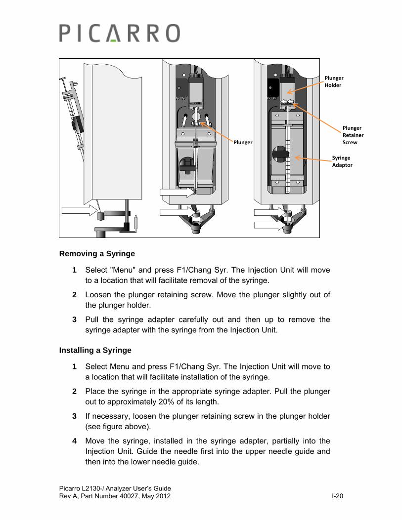
Picarro L2130-i Analyzer User’s Guide Rev A, Part Number 40027, May 2012 I-20
Removing a Syringe
1 Select "Menu" and press F1/Chang Syr. The Injection Unit will move to a location that will facilitate removal of the syringe.
2 Loosen the plunger retaining screw. Move the plunger slightly out of the plunger holder.
3 Pull the syringe adapter carefully out and then up to remove the syringe adapter with the syringe from the Injection Unit.
Installing a Syringe
1 Select Menu and press F1/Chang Syr. The Injection Unit will move to a location that will facilitate installation of the syringe.
2 Place the syringe in the appropriate syringe adapter. Pull the plunger out to approximately 20% of its length.
3 If necessary, loosen the plunger retaining screw in the plunger holder (see figure above).
4 Move the syringe, installed in the syringe adapter, partially into the Injection Unit. Guide the needle first into the upper needle guide and then into the lower needle guide.
Plunger
Plunger Holder
Syringe Adaptor
Plunger Retainer Screw

Picarro L2130-i Analyzer User’s Guide Rev A, Part Number 40027, May 2012 I-21
5 Place the plunger button into the plunger holder. Allow the syringe adapter to "click" into place by magnetic force, against the syringe carrier.
6 Tighten the plunger retaining screw against the plunger button.
7 Press "Continue" on the ‘Replace Syringe’ Window. The plunger moves down until it hits the mechanical stop. This position is stored as the syringes zero volume position. Then the Injection Unit returns to the HOME position.
After replacing a syringe, always check the needle penetration in the injector valve (described in Autosampler training section).
Caution: failure to check the needle penetration can cause permanent damage to the syringe.
Additional syringes can be purchased by ordering the part number “Picarro 01SYR” which is a single 5 µL glass syringe.
Sample Vials
Improper sealing of the sample vial is the most common cause of accidental isotopic fractionation! The caps of the vials can easily be threaded incorrectly. Check the cap is screwed on level to the vial:
Good Vial Bad Vial
Picarro L2130-i Analyzer User’s Guide Rev A, Part Number 40027, May 2012 I-22
Proper capping of vial shown on left, improper capping of vial on right
Additional sample vials can be purchased by ordering the part number “Picarro 01VIA” which is a single package contains 100 units of clear glass, 2mL, 12 x 32mm screw-top vials with a 9mm thread finish.
Additional caps and septa can be purchased by ordering the part number “Picarro 01CAP” which is a single package contains 100 units of 9-mm thread PTFE/Silicone septa to fit 2 ml vial.
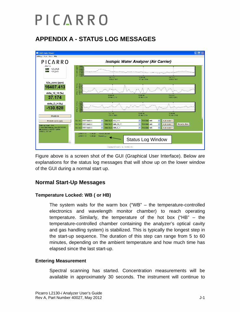
Picarro L2130-i Analyzer User’s Guide Rev A, Part Number 40027, May 2012 J-1
APPENDIX A - STATUS LOG MESSAGES
Figure above is a screen shot of the GUI (Graphical User Interface). Below are explanations for the status log messages that will show up on the lower window of the GUI during a normal start up.
Normal Start-Up Messages
Temperature Locked: WB ( or HB)
The system waits for the warm box (“WB” – the temperature-controlled electronics and wavelength monitor chamber) to reach operating temperature. Similarly, the temperature of the hot box (“HB” – the temperature-controlled chamber containing the analyzer’s optical cavity and gas handling system) is stabilized. This is typically the longest step in the start-up sequence. The duration of this step can range from 5 to 60 minutes, depending on the ambient temperature and how much time has elapsed since the last start-up.
Entering Measurement
Spectral scanning has started. Concentration measurements will be available in approximately 30 seconds. The instrument will continue to
Status Log Window
Picarro L2130-i Analyzer User’s Guide Rev A, Part Number 40027, May 2012 J-2
scan and report concentration measurements until the instrument is shutdown using the procedure below.
Pressure Stabilizing/Locked
The valve control system begins to allow flow through the analyzer and stabilizes the pressure inside the cavity.
Measuring
This is the normal mode of operation after start-up has completed.
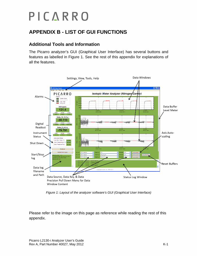
Picarro L2130-i Analyzer User’s Guide Rev A, Part Number 40027, May 2012 K-1
APPENDIX B - LIST OF GUI FUNCTIONS
Additional Tools and Information
The Picarro analyzer’s GUI (Graphical User Interface) has several buttons and features as labelled in Figure 1. See the rest of this appendix for explanations of all the features.
Figure 1: Layout of the analyzer software’s GUI (Graphical User Interface)
Please refer to the image on this page as reference while reading the rest of this appendix.
Picarro L2130-i Analyzer User’s Guide Rev A, Part Number 40027, May 2012 K-2
Settings, Tools and Help Menus:
Settings Menu
Left clicking on the Settings menu pulls down a menu that has one entry ‘Change GUI Mode from Standard to Service’. This is the access point to a password protected service mode where additional operational and measurement parameters are displayed. Selecting and clicking on this entry opens the Cavity Ring-Down Spectrometer Controller.
View Menu
This menu item has three entries:
1. ‘Lock/Unlock time axis when zoomed’: When locked, forces the two graphs to display the same time scale during zoom.
2. ‘Show/hide statistics’: Toggles the measurement statistics display, see ‘Digital Readout’ on the Figure 1.
3. ‘Show/hide instrument status’: Toggles the instruments status display. See ‘Instrument Status’ on the Figure 1.
Tools Menu
This menu item has two entries:
1. User Calibration: Opens the user calibration window (default password is “picarro”). The calibration slope and intercept can be entered and their effects immediately seen in the data. The analyzer should be calibrated based on a linear fit of known value versus measured value for each parameter (D, 18O, H2O concentration etc) with the slope and intercept of the linear fit being used to calibrate. The analyzer is extremely linear and an R2 value of >0.99 should be expected for the fit over reasonable ranges, if the R2 value is lower, then this is an indication other problems. Each background gas or mode has its own independent calibration parameters.

Picarro L2130-i Analyzer User’s Guide Rev A, Part Number 40027, May 2012 K-3
Figure Above: The ‘User Calibration’ Window. Used to set calibration slope and intercept.
2. Show/Hide Valve Sequencer GUI: Toggles the display of the external valve sequencer window. This module will be automatically disabled when a coordinator is run.
Help Menu
About Displays the version number of the instrument.
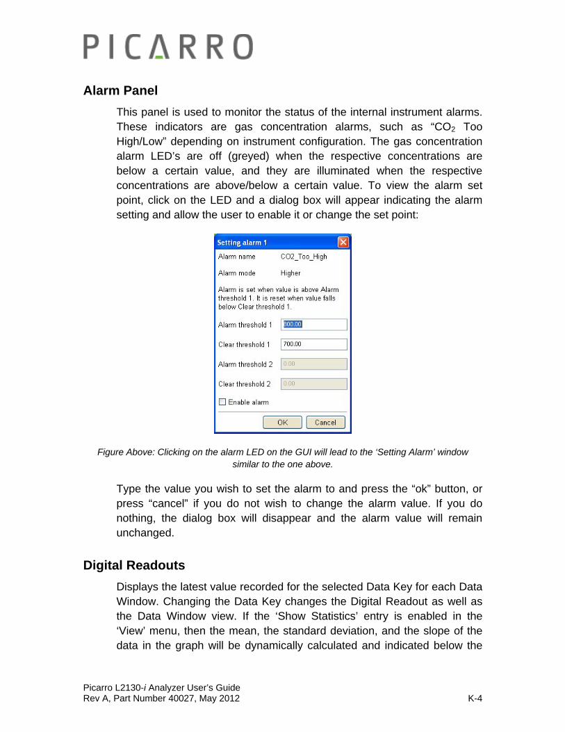
Picarro L2130-i Analyzer User’s Guide Rev A, Part Number 40027, May 2012 K-4
Alarm Panel
This panel is used to monitor the status of the internal instrument alarms. These indicators are gas concentration alarms, such as “CO2 Too High/Low” depending on instrument configuration. The gas concentration alarm LED’s are off (greyed) when the respective concentrations are below a certain value, and they are illuminated when the respective concentrations are above/below a certain value. To view the alarm set point, click on the LED and a dialog box will appear indicating the alarm setting and allow the user to enable it or change the set point:
Figure Above: Clicking on the alarm LED on the GUI will lead to the ‘Setting Alarm’ window similar to the one above.
Type the value you wish to set the alarm to and press the “ok” button, or press “cancel” if you do not wish to change the alarm value. If you do nothing, the dialog box will disappear and the alarm value will remain unchanged.
Digital Readouts
Displays the latest value recorded for the selected Data Key for each Data Window. Changing the Data Key changes the Digital Readout as well as the Data Window view. If the ‘Show Statistics’ entry is enabled in the ‘View’ menu, then the mean, the standard deviation, and the slope of the data in the graph will be dynamically calculated and indicated below the

Picarro L2130-i Analyzer User’s Guide Rev A, Part Number 40027, May 2012 K-5
digital concentration readout. These numbers change to reflect statistics of whatever the data is in the data window.
Restart User Log(s)
The Analyzer automatically records all data collected on the instrument and saves it for later analysis. These files are called *.dat files, which are described below in the section called “File Management”. These files are generated and stored automatically at user defined time intervals. By clicking on the “Restart User Log(s)” button a new data log file is started. It is not possible to turn off data recording, only to start a new file.
Data Log Filename and Path
The filename and path of the active data log is displayed in this pane. A new file will be generated on the hour or at midnight depending upon the user defined time interval and it will be saved to the same location as the original log file.
Data Windows
The data window displays a graph of any stream of data vs. system time, with a format of hh:mm:ss. The user can select which data stream are displayed using combinations from the ‘Data Source’ and ‘Data Key’ pull down menus. The precision displayed can be adjusted using the “Precision” menu and Auto-scaling of the ‘Y’ axis is also available.
Instrument Status
If these parameters are enabled through the ‘Show Instrument Status’ entry in the ‘View’ Menu, the main toolbar digital readouts for Warm Box temperature, Cavity Temperature, and Cavity Pressure will be displayed to the left of the main trend graphs. If these displays show a persistent yellow or an occasional red state then there is a problem. These displays will be in the green state during normal operation.
Data Source and Data Key Pull Down Menus
These two menus enable selection of the data stream that is viewed in the ‘data window’. Data streams available on the GUI are gas concentrations. if ‘instrument Analysis’ (where instrument represents the system installed)

Picarro L2130-i Analyzer User’s Guide Rev A, Part Number 40027, May 2012 K-6
is selected, or if “sensors” is selected, the analyzer’s optical cavity pressure or temperature can be viewed as well as the nominal ambient temperature of the analyzer (“Analyzer temp”) and the temperature of the analyzer’s electronics chamber (indicated as “warm chamber temp”).
For a G2301-f, the “flux sync” selector shows data that is output on equally-spaced intervals in time (at exactly 0.1s intervals) whereas the “flux analysis” shows the data as it is taken, before it has been re-sampled to be at equally-spaced time intervals.
Precision Pull down menu
Click on this icon to select the precision displayed on the y-axis, between 0 and 4 digits of precision or “auto”. The currently selected precision is displayed during operation. This does not affect the precision of the saved data in the data log files or results files.
Status Log Window
This window displays instrument status messages, in the following form: ‘MM/DD/YYYY hh:mm:ss generic message text.’ These messages include all messages sent to the front panel display in the GUI. Some occasional messages are normal during the course of operation. The instrument status should be viewed to determine if there is a persistent problem.
Reset Data Buffer Button
Press this button to clear the internal data buffer of the GUI. This has the effect of clearing all data in the data window. Pressing this button has no effect on any of the data log files stored by the instrument.
Data Buffer Level Meter
The meter to the right of the Data Window indicates how much of the internal memory of the GUI is used to retain historical data collected with the instrument. There is an internal limit of a finite number of points. Once that number of data points is collected, the buffer is full, and old data is removed from the buffer as new data is collected. This buffer affects only the data displayed in the data window, not the data stored in any files. This buffer is empty upon instrument startup, and can also be emptied by

Picarro L2130-i Analyzer User’s Guide Rev A, Part Number 40027, May 2012 K-7
pressing the reset data buffer button in the lower-right-hand corner of the GUI.
Graph Zooming
To zoom the graph, simply drag the magnifying glass over the section to be zoomed and click and hold the left mouse button. While holding down the left button, move the mouse to create a box that covers the region of interest. When the box is properly drawn, release the left button and boxed area will automatically scale to fill the data window. To zoom back out, double click on the left button. To autoscale the y-axis of either graph, use the autoscale buttons below the graph. To lock or unlock the time axes of each graph during zooming, select that menu item in the ‘View’ menu.

Picarro L2130-i Analyzer User’s Guide Rev A, Part Number 40027, May 2012 K-8
File Management
During operation, the Analyzer generates various ASCII-format text output files that are updated after each batch of concentration measurements is complete. For example, one of the user output files is named CFBDS##-yyyymmdd-hhmmss-DataLog_User.dat where “CFBDS##” or similar is the instrument serial number.
The file name is generated from the instrument serial number, the date, and the time when the instrument was started. For example:
HIDSS01-20070127-102915-DataLog_User.dat
HIDSS01 is the instrument serial number
20070127 is the date, 1/27/2007, in format yyyymmdd (to allow chronological sorting of data files).
102915 is the time the file was started, 10:29:15 am, formatted as hhmmss using a 24 hour clock.
The user data is contained in folders in the directory:
C:\UserData \DataLog_User\[year]\[month]\[day]\[hour].
File frequency (i.e. saving hourly, daily) is defined using the setup tool.
The file archiving and deletion frequency and details defined using the setup tool.

Picarro L2130-i Analyzer User’s Guide Rev A, Part Number 40027, May 2012 K-9
Setup Tool for File Management
To change file management parameters for your data, open the directory “Picarro Utilities” which can be found on the computer desktop. Double click on the setup tool.
Figure Above: Where you can find the setup tool for file management.
The setup tool consists of multiple tabs. The first tab ‘data logger’ contains file management components. See the image and descriptions below for more information.
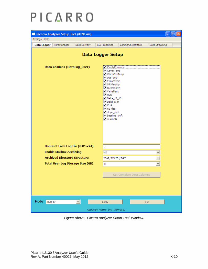
Picarro L2130-i Analyzer User’s Guide Rev A, Part Number 40027, May 2012 K-10
Figure Above: ‘Picarro Analyzer Setup Tool’ Window.

Picarro L2130-i Analyzer User’s Guide Rev A, Part Number 40027, May 2012 K-11
Hours of Each Log File
Specifies the time span of each file in hours. 24 hours is a daily file which is manageable for most models. For high data rate models such as used for flux measurements, the recommended maximum is 1 hour.
Archived Directory Structure
Specifies how many directory levels are used to separate log files saved in C:\UserData\.
Total User Log Storage Size:
Specifies how much data in GB can be saved in the user log before archiving occurs. A typical model analyzer (L2130-i isotopic water) generates approximately 45 MB of user data files each day. A high speed analyzer running in flux mode generates approximately 700 MB of user data files each day. If the default size of 30 GB is used, this means approximately 22 months of typical data or 43 days of flux data can be stored.
Once the specified size is reached, the oldest files will be automatically deleted. Please back up your data before this occurs! The analyzer is equipped with software running in the background to manage hard disk space - it will delete older (non-user) files to prevent the hard disk becoming full. Contact Picarro for further details on this if required and in the event of loss of user data it may be possible to retrieve data using this software.
Data Columns (UserLog_Data):
This is used to include additional data in the userlog data file. Analyzers are factory configured to include all commonly used data for that model. However, it is possible to add or remove as needed. The main analyzer software must be stopped in order to do this. Select or deselect the desired data columns and select to apply, and then restart the software. Please consult with Picarro to find out more about the specific data columns.

Picarro L2130-i Analyzer User’s Guide Rev A, Part Number 40027, May 2012 K-12
There are more complete data files which include additional information beyond the concentration data including parameters such as instrument temperatures and pressure, setpoints and spectroscopic information. This information is generally not useful to the user, but can be useful for diagnostic purposes and is store in the directory:
C:\Picarro\G2000\Log\DataLog_Private \[year]\[month]\[day]\[hour].
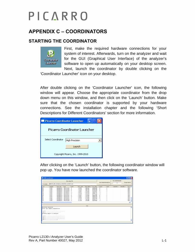
Picarro L2130-i Analyzer User’s Guide Rev A, Part Number 40027, May 2012 L-1
APPENDIX C – COORDINATORS
STARTING THE COORDINATOR
First, make the required hardware connections for your system of interest. Afterwards, turn on the analyzer and wait for the GUI (Graphical User Interface) of the analyzer’s software to open up automatically on your desktop screen. Next, launch the coordinator by double clicking on the
‘Coordinator Launcher’ icon on your desktop.
After double clicking on the ‘Coordinator Launcher’ icon, the following window will appear. Choose the appropriate coordinator from the drop down menu on this window, and then click on the ‘Launch’ button. Make sure that the chosen coordinator is supported by your hardware connections. See the installation chapter and the following ‘Short Descriptions for Different Coordinators’ section for more information.
After clicking on the ‘Launch’ button, the following coordinator window will pop up. You have now launched the coordinator software.
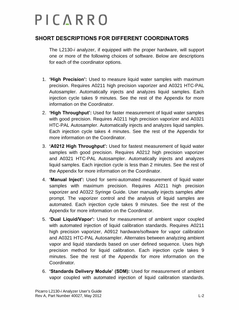
Picarro L2130-i Analyzer User’s Guide Rev A, Part Number 40027, May 2012 L-2
SHORT DESCRIPTIONS FOR DIFFERENT COORDINATORS
The L2130-i analyzer, if equipped with the proper hardware, will support one or more of the following choices of software. Below are descriptions for each of the coordinator options.
1. ‘High Precision’: Used to measure liquid water samples with maximum precision. Requires A0211 high precision vaporizer and A0321 HTC-PAL Autosampler. Automatically injects and analyzes liquid samples. Each injection cycle takes 9 minutes. See the rest of the Appendix for more information on the Coordinator.
2. ‘High Throughput’: Used for faster measurement of liquid water samples with good precision. Requires A0211 high precision vaporizer and A0321 HTC-PAL Autosampler. Automatically injects and analyzes liquid samples. Each injection cycle takes 4 minutes. See the rest of the Appendix for more information on the Coordinator.
3. ‘A0212 High Throughput’: Used for fastest measurement of liquid water samples with good precision. Requires A0212 high precision vaporizer and A0321 HTC-PAL Autosampler. Automatically injects and analyzes liquid samples. Each injection cycle is less than 2 minutes. See the rest of the Appendix for more information on the Coordinator.
4. ‘Manual Inject’: Used for semi-automated measurement of liquid water samples with maximum precision. Requires A0211 high precision vaporizer and A0322 Syringe Guide. User manually injects samples after prompt. The vaporizer control and the analysis of liquid samples are automated. Each injection cycle takes 9 minutes. See the rest of the Appendix for more information on the Coordinator.
5. ‘Dual Liquid/Vapor’: Used for measurement of ambient vapor coupled with automated injection of liquid calibration standards. Requires A0211 high precision vaporizer, A0912 hardware/software for vapor calibration and A0321 HTC-PAL Autosampler. Alternates between analyzing ambient vapor and liquid standards based on user defined sequence. Uses high precision method for liquid calibration. Each injection cycle takes 9 minutes. See the rest of the Appendix for more information on the Coordinator.
6. ‘Standards Delivery Module’ (SDM): Used for measurement of ambient vapor coupled with automated injection of liquid calibration standards.

Picarro L2130-i Analyzer User’s Guide Rev A, Part Number 40027, May 2012 L-3
Requires A0211 high precision vaporizer and A0101 standards delivery module. Alternates between analyzing ambient vapor from multiple points and a continuous stream of vaporized standard. The alternation is based on user defined sequence. A calibration measurement takes approximately 20 minutes per concentration/standard. See the SDM Operation chapter in this manual for more information on the usage of the SDM Coordinator.
7. ‘IM CRDS’ (Induction Module): Used for isotopic analysis of extracted water from samples such as soil, plants, or tissues and allows the isotopic analysis of the extracted water. See the Induction Module manual for more information on the usage of Induction Module Coordinator.

Picarro L2130-i Analyzer User’s Guide Rev A, Part Number 40027, May 2012 L-4
HIGH PRECISION & HIGH THROUGHPUT COORDINATOR
Both coordinators (High Precision & High Throughput) operate in the exact same fashion except that the steps of sample preparation and analysis are faster in the high throughput coordinator.
Set the vaporizer temperature to 110 C° for operation. Use the up/down buttons to adjust the set point and to allow it to stabilize before proceeding. Higher temperatures will reduce the lifetime of the vaporizer components. Remember that for the SDM operation, the temperature should be set to 140 C°. For all the other coordinator modes, the temperature should be set to 110 C°.
Above is an image of the vaporizer.
Verify the hardware connections to the vaporizer are for this coordinator mode. For example, using the dual liquid/vapour valve with these coordinators will cause errors in the data.

Picarro L2130-i Analyzer User’s Guide Rev A, Part Number 40027, May 2012 L-5
Opening the Coordinator Window:
The following Coordinator window will pop up after choosing the coordinator mode from the drop down menu on the Picarro Coordinator Launcher window.
Descriptions of the Coordinator Window:
The top bar of the coordinator window has three buttons. Below are descriptions for each buttons.
1. CHANGE SEPTUM BUTTON: Located at the upper right corner of the Coordinator Window. Used to pause the Autosampler and the vaporizer in middle of an analysis to physically change the septum on the vaporizer (See the ‘changing injector port septa’ section at the end of this appendix for more information). After clicking on the ‘change septum’ button, the button will display the words ‘Please wait…’ until the current injection analysis becomes complete. Once it is ready, the button will become enabled again and the status bar at the bottom of the window will display ‘CHANGE SEPTUM: Press ‘Septum Changed’ when complete.’ At this point, you can change the septa. Once the septa has been changed, press the ‘septum changed’ button to continue with the analysis. Images below are screen shots of the upper right corner of the coordinator window during the steps described in this paragraph.

Picarro L2130-i Analyzer User’s Guide Rev A, Part Number 40027, May 2012 L-6
Step 1: Click on the ‘Change Septum’ button.
Step 2: Notice the ‘Please Wait’ sign on the same button. Wait until the button becomes enabled again.
Step 3: Notice the ‘Septum Changed’ sign on the same button. During this time, change the Septum. Afterwards, click on the ‘Septum Changed’ button.
2. LOAD SAMPLE DESCRIPTIONS BUTTON: Located around the upper right corner of the Coordinator Window. The button allows the user to include a description for each vial in the data file output on the coordinator window.

Picarro L2130-i Analyzer User’s Guide Rev A, Part Number 40027, May 2012 L-7
Figure Above: Where to find the ‘Load Sample Descriptions’ Button.
In order to load the sample description file, press the button labelled ‘Load Sample Descriptions’. Two file dialog boxes will appear in sequence, the first for the front tray and the second for the rear tray of the Autosampler. Select the sample description file, and then click to ‘Open’. If a certain tray (front or rear) is not being used, use the ‘Cancel’ button to dismiss the dialog.
Figure above: ‘Sample Description File for Tray MT1-Frnt’ window. The file above was saved in the Coordinator folder, however it can be saved in any location.

Picarro L2130-i Analyzer User’s Guide Rev A, Part Number 40027, May 2012 L-8
Figure above: ‘Sample Description File for tray MT1-Rear’ window. The file above was saved in the Coordinator folder, however it can be saved in any location.
HOW TO MAKE THE SAMPLE DESCRIPTION FILE
The sample description file should be in CSV (comma separated value) format. Use the supplied NotePad++ software. Write the sample descriptions in the format as shown below.
Tray,Vial,Identifier 1,Identifier 2
1,1,Picarro 00,standard
1,2,Picarro 11, standard
1,3,Picarro 22, standard
1,4,WA 1,first sample from Washington
1,5,WA 2,second sample from Washington
1,6,CA 1, first sample from California
1,7,CA 2, second sample from California
1,8,Picarro 00, standard
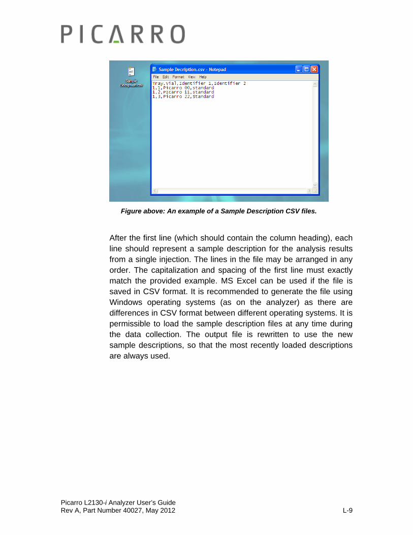
Picarro L2130-i Analyzer User’s Guide Rev A, Part Number 40027, May 2012 L-9
Figure above: An example of a Sample Description CSV files.
After the first line (which should contain the column heading), each line should represent a sample description for the analysis results from a single injection. The lines in the file may be arranged in any order. The capitalization and spacing of the first line must exactly match the provided example. MS Excel can be used if the file is saved in CSV format. It is recommended to generate the file using Windows operating systems (as on the analyzer) as there are differences in CSV format between different operating systems. It is permissible to load the sample description files at any time during the data collection. The output file is rewritten to use the new sample descriptions, so that the most recently loaded descriptions are always used.
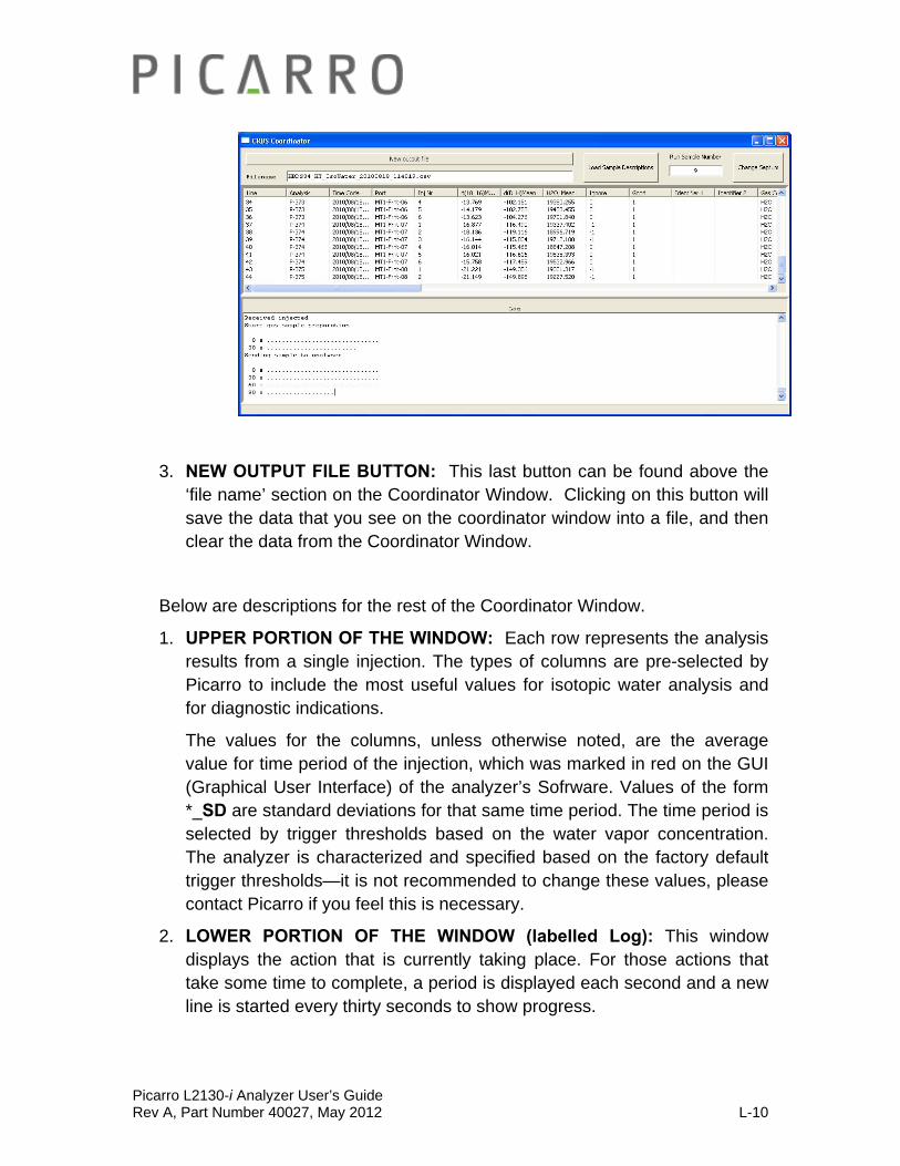
Picarro L2130-i Analyzer User’s Guide Rev A, Part Number 40027, May 2012 L-10
3. NEW OUTPUT FILE BUTTON: This last button can be found above the ‘file name’ section on the Coordinator Window. Clicking on this button will save the data that you see on the coordinator window into a file, and then clear the data from the Coordinator Window.
Below are descriptions for the rest of the Coordinator Window.
1. UPPER PORTION OF THE WINDOW: Each row represents the analysis results from a single injection. The types of columns are pre-selected by Picarro to include the most useful values for isotopic water analysis and for diagnostic indications.
The values for the columns, unless otherwise noted, are the average value for time period of the injection, which was marked in red on the GUI (Graphical User Interface) of the analyzer’s Sofrware. Values of the form *_SD are standard deviations for that same time period. The time period is selected by trigger thresholds based on the water vapor concentration. The analyzer is characterized and specified based on the factory default trigger thresholds—it is not recommended to change these values, please contact Picarro if you feel this is necessary.
2. LOWER PORTION OF THE WINDOW (labelled Log): This window displays the action that is currently taking place. For those actions that take some time to complete, a period is displayed each second and a new line is started every thirty seconds to show progress.
Picarro L2130-i Analyzer User’s Guide Rev A, Part Number 40027, May 2012 L-11
3. COORDINATOR OUTPUT FILENAME: Can be seen in the upper left of the Coordinator window. It follows an automated convention of –
model, serial number, mode, year, month, date, and time. For example
HBDS34_HT_IsoWater_20100818_114019
This means the coordinator file output was taken using analyzer HBDS34 in high throughput isotopic water analysis starting on 18 August 2010 at 11:40:19 am.
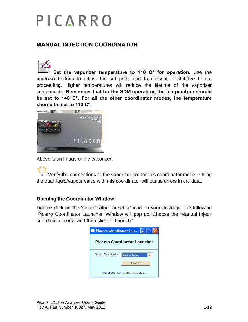
Picarro L2130-i Analyzer User’s Guide Rev A, Part Number 40027, May 2012 L-12
MANUAL INJECTION COORDINATOR
Set the vaporizer temperature to 110 C° for operation. Use the up/down buttons to adjust the set point and to allow it to stabilize before proceeding. Higher temperatures will reduce the lifetime of the vaporizer components. Remember that for the SDM operation, the temperature should be set to 140 C°. For all the other coordinator modes, the temperature should be set to 110 C°.
Above is an image of the vaporizer.
Verify the connections to the vaporizer are for this coordinator mode. Using the dual liquid/vapour valve with this coordinator will cause errors in the data.
Opening the Coordinator Window:
Double click on the ‘Coordinator Launcher’ icon on your desktop. The following ‘Picarro Coordinator Launcher’ Window will pop up. Choose the ‘Manual Inject’ coordinator mode, and then click to ‘Launch.’
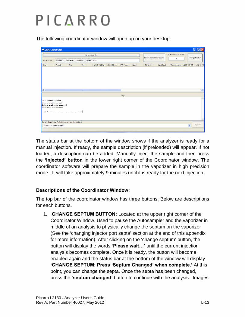
Picarro L2130-i Analyzer User’s Guide Rev A, Part Number 40027, May 2012 L-13
The following coordinator window will open up on your desktop.
The status bar at the bottom of the window shows if the analyzer is ready for a manual injection. If ready, the sample description (if preloaded) will appear. If not loaded, a description can be added. Manually inject the sample and then press the ‘Injected’ button in the lower right corner of the Coordinator window. The coordinator software will prepare the sample in the vaporizer in high precision mode. It will take approximately 9 minutes until it is ready for the next injection.
Descriptions of the Coordinator Window:
The top bar of the coordinator window has three buttons. Below are descriptions for each buttons.
1. CHANGE SEPTUM BUTTON: Located at the upper right corner of the Coordinator Window. Used to pause the Autosampler and the vaporizer in middle of an analysis to physically change the septum on the vaporizer (See the ‘changing injector port septa’ section at the end of this appendix for more information). After clicking on the ‘change septum’ button, the button will display the words ‘Please wait…’ until the current injection analysis becomes complete. Once it is ready, the button will become enabled again and the status bar at the bottom of the window will display ‘CHANGE SEPTUM: Press ‘Septum Changed’ when complete.’ At this point, you can change the septa. Once the septa has been changed, press the ‘septum changed’ button to continue with the analysis. Images
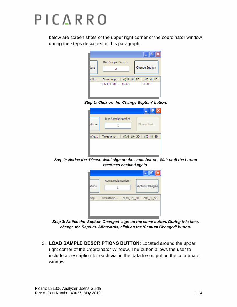
Picarro L2130-i Analyzer User’s Guide Rev A, Part Number 40027, May 2012 L-14
below are screen shots of the upper right corner of the coordinator window during the steps described in this paragraph.
Step 1: Click on the ‘Change Septum’ button.
Step 2: Notice the ‘Please Wait’ sign on the same button. Wait until the button becomes enabled again.
Step 3: Notice the ‘Septum Changed’ sign on the same button. During this time, change the Septum. Afterwards, click on the ‘Septum Changed’ button.
2. LOAD SAMPLE DESCRIPTIONS BUTTON: Located around the upper right corner of the Coordinator Window. The button allows the user to include a description for each vial in the data file output on the coordinator window.
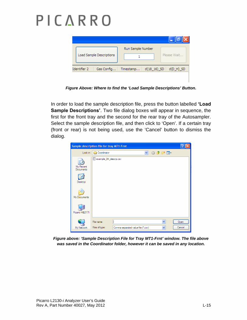
Picarro L2130-i Analyzer User’s Guide Rev A, Part Number 40027, May 2012 L-15
Figure Above: Where to find the ‘Load Sample Descriptions’ Button.
In order to load the sample description file, press the button labelled ‘Load Sample Descriptions’. Two file dialog boxes will appear in sequence, the first for the front tray and the second for the rear tray of the Autosampler. Select the sample description file, and then click to ‘Open’. If a certain tray (front or rear) is not being used, use the ‘Cancel’ button to dismiss the dialog.
Figure above: ‘Sample Description File for Tray MT1-Frnt’ window. The file above was saved in the Coordinator folder, however it can be saved in any location.

Picarro L2130-i Analyzer User’s Guide Rev A, Part Number 40027, May 2012 L-16
Figure above: ‘Sample Description File for tray MT1-Rear’ window. The file above was saved in the Coordinator folder, however it can be saved in any location.
HOW TO MAKE THE SAMPLE DESCRIPTION FILE
The sample description file should be in CSV (comma separated value) format. Use the supplied NotePad++ software. Write the sample descriptions in the format as shown below.
Tray,Vial,Identifier 1,Identifier 2
1,1,Picarro 00,standard
1,2,Picarro 11, standard
1,3,Picarro 22, standard
1,4,WA 1,first sample from Washington
1,5,WA 2,second sample from Washington
1,6,CA 1, first sample from California
1,7,CA 2, second sample from California
1,8,Picarro 00, standard

Picarro L2130-i Analyzer User’s Guide Rev A, Part Number 40027, May 2012 L-17
Figure above: An example of a Sample Description CSV files.
After the first line (which should contain the column heading), each line should represent a sample description for the analysis results from a single injection. The lines in the file may be arranged in any order. The capitalization and spacing of the first line must exactly match the provided example. MS Excel can be used if the file is saved in CSV format. It is recommended to generate the file using Windows operating systems (as on the analyzer) as there are differences in CSV format between different operating systems. It is permissible to load the sample description files at any time during the data collection. The output file is rewritten to use the new sample descriptions, so that the most recently loaded descriptions are always used.
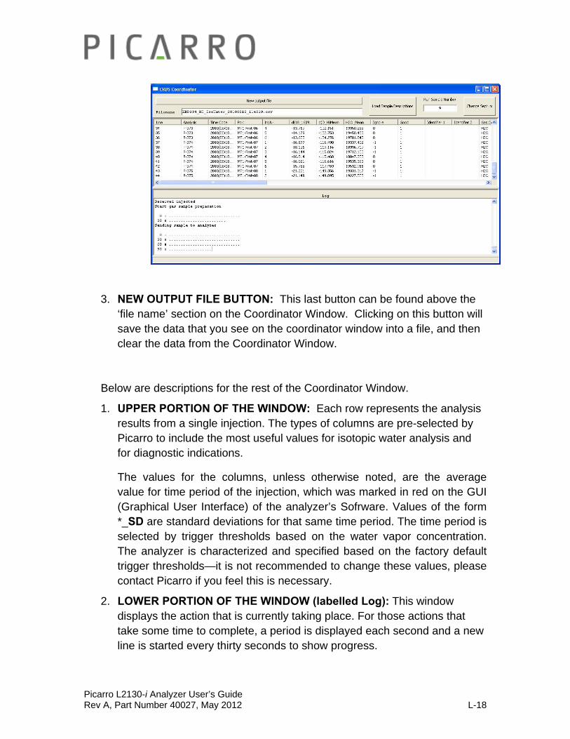
Picarro L2130-i Analyzer User’s Guide Rev A, Part Number 40027, May 2012 L-18
3. NEW OUTPUT FILE BUTTON: This last button can be found above the ‘file name’ section on the Coordinator Window. Clicking on this button will save the data that you see on the coordinator window into a file, and then clear the data from the Coordinator Window.
Below are descriptions for the rest of the Coordinator Window.
1. UPPER PORTION OF THE WINDOW: Each row represents the analysis results from a single injection. The types of columns are pre-selected by Picarro to include the most useful values for isotopic water analysis and for diagnostic indications.
The values for the columns, unless otherwise noted, are the average value for time period of the injection, which was marked in red on the GUI (Graphical User Interface) of the analyzer’s Sofrware. Values of the form *_SD are standard deviations for that same time period. The time period is selected by trigger thresholds based on the water vapor concentration. The analyzer is characterized and specified based on the factory default trigger thresholds—it is not recommended to change these values, please contact Picarro if you feel this is necessary.
2. LOWER PORTION OF THE WINDOW (labelled Log): This window displays the action that is currently taking place. For those actions that take some time to complete, a period is displayed each second and a new line is started every thirty seconds to show progress.

Picarro L2130-i Analyzer User’s Guide Rev A, Part Number 40027, May 2012 L-19
3. COORDINATOR OUTPUT FILENAME: Can be seen in the upper left of the Coordinator window. It follows an automated convention of –
model, serial number, mode, year, month, date, and time. For example
HIDS34_HT_IsoWater_20100818_114019
This means the coordinator file output was taken using analyzer HIDS34 in high throughput isotopic water analysis starting on 18 August 2010 at 11:40:19 am.
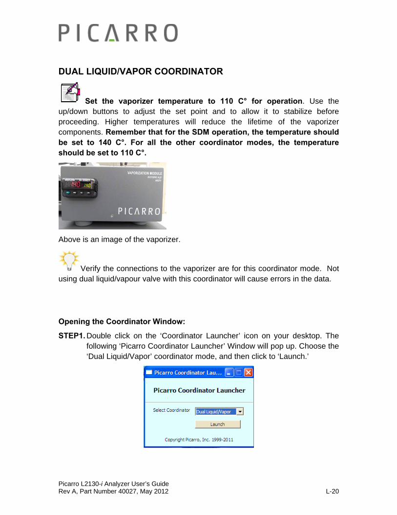
Picarro L2130-i Analyzer User’s Guide Rev A, Part Number 40027, May 2012 L-20
DUAL LIQUID/VAPOR COORDINATOR
Set the vaporizer temperature to 110 C° for operation. Use the up/down buttons to adjust the set point and to allow it to stabilize before proceeding. Higher temperatures will reduce the lifetime of the vaporizer components. Remember that for the SDM operation, the temperature should be set to 140 C°. For all the other coordinator modes, the temperature should be set to 110 C°.
Above is an image of the vaporizer.
Verify the connections to the vaporizer are for this coordinator mode. Not using dual liquid/vapour valve with this coordinator will cause errors in the data.
Opening the Coordinator Window:
STEP1. Double click on the ‘Coordinator Launcher’ icon on your desktop. The following ‘Picarro Coordinator Launcher’ Window will pop up. Choose the ‘Dual Liquid/Vapor’ coordinator mode, and then click to ‘Launch.’
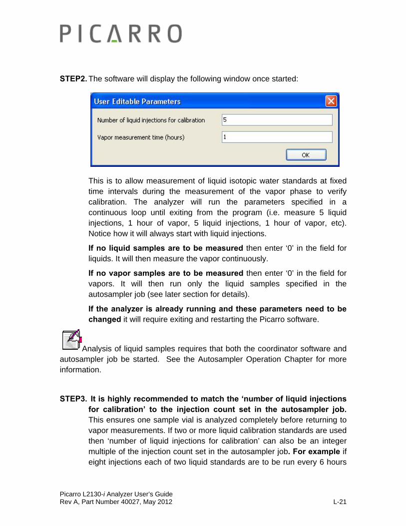
Picarro L2130-i Analyzer User’s Guide Rev A, Part Number 40027, May 2012 L-21
STEP2. The software will display the following window once started:
This is to allow measurement of liquid isotopic water standards at fixed time intervals during the measurement of the vapor phase to verify calibration. The analyzer will run the parameters specified in a continuous loop until exiting from the program (i.e. measure 5 liquid injections, 1 hour of vapor, 5 liquid injections, 1 hour of vapor, etc). Notice how it will always start with liquid injections.
If no liquid samples are to be measured then enter ‘0’ in the field for liquids. It will then measure the vapor continuously.
If no vapor samples are to be measured then enter ‘0’ in the field for vapors. It will then run only the liquid samples specified in the autosampler job (see later section for details).
If the analyzer is already running and these parameters need to be changed it will require exiting and restarting the Picarro software.
Analysis of liquid samples requires that both the coordinator software and autosampler job be started. See the Autosampler Operation Chapter for more information.
STEP3. It is highly recommended to match the ‘number of liquid injections for calibration’ to the injection count set in the autosampler job. This ensures one sample vial is analyzed completely before returning to vapor measurements. If two or more liquid calibration standards are used then ‘number of liquid injections for calibration’ can also be an integer multiple of the injection count set in the autosampler job. For example if eight injections each of two liquid standards are to be run every 6 hours
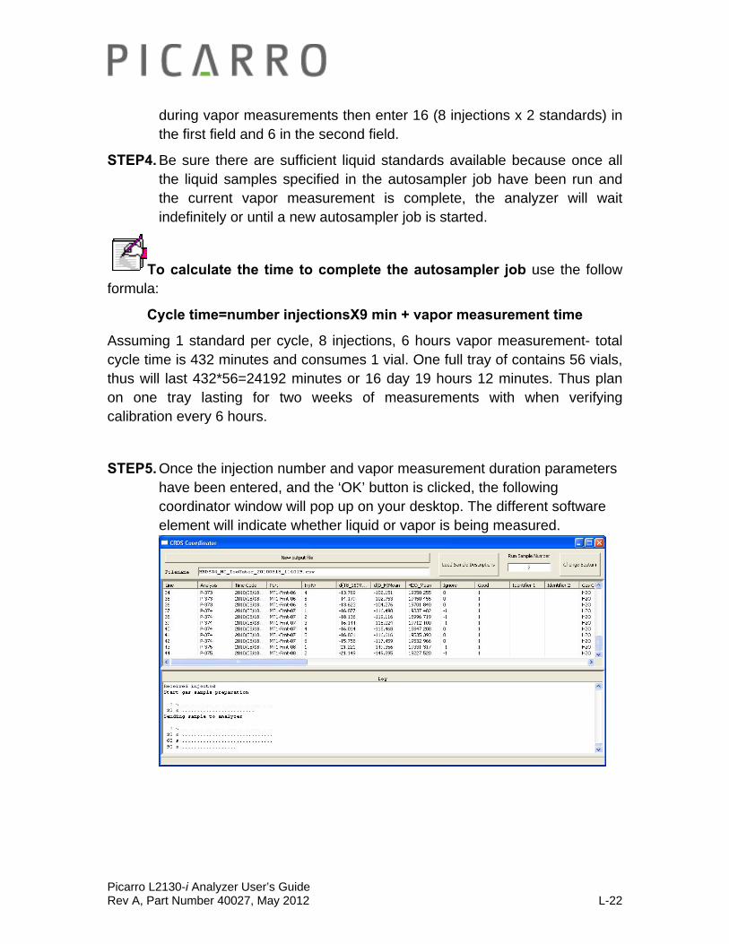
Picarro L2130-i Analyzer User’s Guide Rev A, Part Number 40027, May 2012 L-22
during vapor measurements then enter 16 (8 injections x 2 standards) in the first field and 6 in the second field.
STEP4. Be sure there are sufficient liquid standards available because once all the liquid samples specified in the autosampler job have been run and the current vapor measurement is complete, the analyzer will wait indefinitely or until a new autosampler job is started.
To calculate the time to complete the autosampler job use the follow formula:
Cycle time=number injectionsX9 min + vapor measurement time
Assuming 1 standard per cycle, 8 injections, 6 hours vapor measurement- total cycle time is 432 minutes and consumes 1 vial. One full tray of contains 56 vials, thus will last 432*56=24192 minutes or 16 day 19 hours 12 minutes. Thus plan on one tray lasting for two weeks of measurements with when verifying calibration every 6 hours.
STEP5. Once the injection number and vapor measurement duration parameters have been entered, and the ‘OK’ button is clicked, the following coordinator window will pop up on your desktop. The different software element will indicate whether liquid or vapor is being measured.
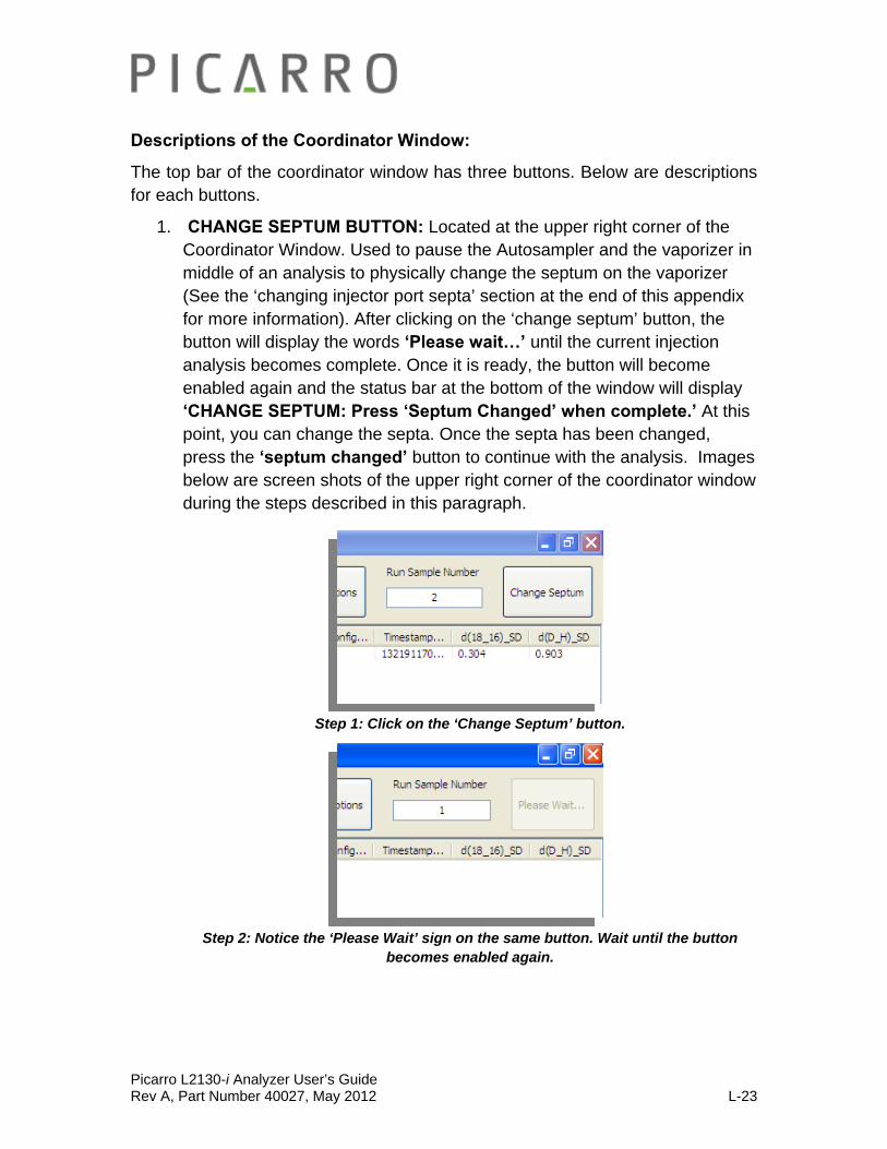
Picarro L2130-i Analyzer User’s Guide Rev A, Part Number 40027, May 2012 L-23
Descriptions of the Coordinator Window:
The top bar of the coordinator window has three buttons. Below are descriptions for each buttons.
1. CHANGE SEPTUM BUTTON: Located at the upper right corner of the Coordinator Window. Used to pause the Autosampler and the vaporizer in middle of an analysis to physically change the septum on the vaporizer (See the ‘changing injector port septa’ section at the end of this appendix for more information). After clicking on the ‘change septum’ button, the button will display the words ‘Please wait…’ until the current injection analysis becomes complete. Once it is ready, the button will become enabled again and the status bar at the bottom of the window will display ‘CHANGE SEPTUM: Press ‘Septum Changed’ when complete.’ At this point, you can change the septa. Once the septa has been changed, press the ‘septum changed’ button to continue with the analysis. Images below are screen shots of the upper right corner of the coordinator window during the steps described in this paragraph.
Step 1: Click on the ‘Change Septum’ button.
Step 2: Notice the ‘Please Wait’ sign on the same button. Wait until the button becomes enabled again.

Picarro L2130-i Analyzer User’s Guide Rev A, Part Number 40027, May 2012 L-24
Step 3: Notice the ‘Septum Changed’ sign on the same button. During this time, change the Septum. Afterwards, click on the ‘Septum Changed’ button.
2. LOAD SAMPLE DESCRIPTIONS BUTTON: Located around the upper right corner of the Coordinator Window. The button allows the user to include a description for each vial in the data file output on the coordinator window.
Figure Above: Where to find the ‘Load Sample Descriptions’ Button.
In order to load the sample description file, press the button labelled ‘Load Sample Descriptions’. Two file dialog boxes will appear in sequence, the first for the front tray and the second for the rear tray of the Autosampler. Select the sample description file, and then click to ‘Open’. If a certain tray (front or rear) is not being used, use the ‘Cancel’ button to dismiss the dialog.

Picarro L2130-i Analyzer User’s Guide Rev A, Part Number 40027, May 2012 L-25
Figure above: ‘Sample Description File for Tray MT1-Frnt’ window. The file above was saved in the Coordinator folder, however it can be saved in any location.
Figure above: ‘Sample Description File for tray MT1-Rear’ window. The file above was saved in the Coordinator folder, however it can be saved in any location.
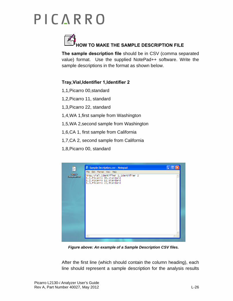
Picarro L2130-i Analyzer User’s Guide Rev A, Part Number 40027, May 2012 L-26
HOW TO MAKE THE SAMPLE DESCRIPTION FILE
The sample description file should be in CSV (comma separated value) format. Use the supplied NotePad++ software. Write the sample descriptions in the format as shown below.
Tray,Vial,Identifier 1,Identifier 2
1,1,Picarro 00,standard
1,2,Picarro 11, standard
1,3,Picarro 22, standard
1,4,WA 1,first sample from Washington
1,5,WA 2,second sample from Washington
1,6,CA 1, first sample from California
1,7,CA 2, second sample from California
1,8,Picarro 00, standard
Figure above: An example of a Sample Description CSV files.
After the first line (which should contain the column heading), each line should represent a sample description for the analysis results

Picarro L2130-i Analyzer User’s Guide Rev A, Part Number 40027, May 2012 L-27
from a single injection. The lines in the file may be arranged in any order. The capitalization and spacing of the first line must exactly match the provided example. MS Excel can be used if the file is saved in CSV format. It is recommended to generate the file using Windows operating systems (as on the analyzer) as there are differences in CSV format between different operating systems. It is permissible to load the sample description files at any time during the data collection. The output file is rewritten to use the new sample descriptions, so that the most recently loaded descriptions are always used.
3. NEW OUTPUT FILE BUTTON: This last button can be found above the ‘file name’ section on the Coordinator Window. Clicking on this button will save the data that you see on the coordinator window into a file, and then clear the data from the Coordinator Window.
Below are descriptions for the rest of the Coordinator Window.
1. UPPER PORTION OF THE WINDOW: Each row represents the analysis results from a single injection. The types of columns are pre-selected by Picarro to include the most useful values for isotopic water analysis and for diagnostic indications.
The values for the columns, unless otherwise noted, are the average value for time period of the injection, which was marked in red on the GUI (Graphical User Interface) of the analyzer’s Sofrware. Values of the form

Picarro L2130-i Analyzer User’s Guide Rev A, Part Number 40027, May 2012 L-28
*_SD are standard deviations for that same time period. The time period is selected by trigger thresholds based on the water vapor concentration. The analyzer is characterized and specified based on the factory default trigger thresholds—it is not recommended to change these values, please contact Picarro if you feel this is necessary.
2. LOWER PORTION OF THE WINDOW (labelled Log): This window displays the action that is currently taking place. For those actions that take some time to complete, a period is displayed each second and a new line is started every thirty seconds to show progress.
3. COORDINATOR OUTPUT FILENAME: Can be seen in the upper left of the Coordinator window. It follows an automated convention of –
model, serial number, mode, year, month, date, and time. For example
HBDS34_HT_IsoWater_20100818_114019
This means the coordinator file output was taken using analyzer HBDS34 in high throughput isotopic water analysis starting on 18 August 2010 at 11:40:19 am.

Picarro L2130-i Analyzer User’s Guide Rev A, Part Number 40027, May 2012 L-29
CHANGING THE INJECTOR PORT SEPTA
The injector port septa should be replaced every 200-300 injections. The more closely grouped needle piercing on the septa, the earlier the septa will need to be replaced. If the septum is not changed, it will be difficult to maintain the vacuum inside the vaporizer which will degrade the quality of the data.
STEP1. To change the vaporizer injection port septum when an autosampler job is running (i.e. actively injecting samples), press the ‘change injector septum’ button on the coordinator software. The analyzer will fill the vaporizer with dry gas. If the autosampler is not running a job then proceed directly to step 3. If no job is running and the ‘change injector septum’ button is pressed the coordinator software will wait indefinitely (to resolve this either start a job on the autosampler or manually end the coordinator software).
STEP2. Wait for the software indication to change the septum.
STEP3. Remove the protective metal cover around the injection port (ensure that the insulation foam stays attached to the cover).
STEP4. Unscrew the cap of the port.
Warning: the bottom of the cap is very hot!
Picarro L2130-i Analyzer User’s Guide Rev A, Part Number 40027, May 2012 L-30
STEP5. The old septum will usually stick to the port, but if it is in the cap, remove it using tweezers (again the port and cap are really hot!).
STEP6. Insert a new septum into the cap and screw the cap onto the port by
hand until it comes to a hard stop. It should be finger tight only.
CAUTION: do not over-tighten or use a wrench, the injector port will be damaged.
STEP7. Replace the metal cover around the injector port. STEP8. Press ‘continue’ on the user interface; the analyzer will restart the vaporizer purge cycle and then wait for the next sample injection.

Picarro L2130-i Analyzer User’s Guide Rev A, Part Number 40027, May 2012 L-31
ADJUSTING INJECTION VOLUME (Relevant to All Except for the SDM/Standard Delivery Module)
For best results, liquid sample injections should be provided to the instrument at a concentration of 20,000 ± 1000ppmv (parts per million by volume). Each liquid injection will be labelled as ‘good’ in the coordinator if this concentration is between 17,000 - 23,000ppmv. If the concentration is significantly above/below this range (i.e. <6,500ppmv or >25,000ppmv) or if the dry background is >500ppmv, the pulse will not be analyzed and the data will not appear in the coordinator.
To achieve the appropriate injection concentration:
1. Dry nitrogen (<50ppmv water concentration) should be supplied to the instrument at 2.5±0.2psi (17.2±1.4kPa), supplied at 200sccm (Standard Cubic Centimeters per Minute). If Drierite (or similar) is used for the dry air (rather than nitrogen) supply, a measured level of ~100-200ppmv will produce satisfactory data. Specifications are guaranteed only with dry nitrogen supply. Dry air can be used but will require a software change to account for the calibration shift from nitrogen. Contact Picarro for details on the software change.
2. Sample injection volume (controlled by Autosampler) should be set at ~2μL.
If the resulting concentration peak after the 2nd or 3rd liquid injection is substantially different from 20,000ppmv:
1. The injection volume may need to be scaled appropriately: for example, if the resulting concentration peak of an initial ‘test’ injection is 16,000ppmv, then the injection volume needs to be adjusted by the factor 20,000/16,000 = 1.25. To accomplish this, multiply the current injection volume in the Autosampler method by 1.25.
2. The injection quality may need improvement. Bad Injections can cause incorrect injection concentrations. Bad injections can be from a clogged needle, damaged vaporizer septum, or incorrect dry gas pressure/flow restriction. For rapid optimization of injection volume use the high throughput coordinator.

Picarro L2130-i Analyzer User’s Guide Rev A, Part Number 40027, May 2012 L-32
Five failed injections will lead to a Time Out: Every time there is a liquid injection into a vaporizer by the SDM, there should be a pulse of water from the end of the needle, after which the pulse should become analyzed for data. If something goes wrong (e.g. syringe breaks), and the pulse analysis doesn’t happen, the software will try injecting five times in a row. If data analysis doesn’t happen after five times of trying, the coordinator will become timed out. You will need to restart the coordinator to continue on with the experiment. This happens as a safety mechanism - If the needle continues to make holes in vial septa, it will increase the likelihood of sample contamination.
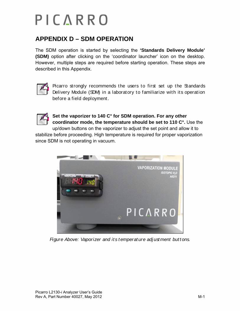
Picarro L2130-i Analyzer User’s Guide Rev A, Part Number 40027, May 2012 M-1
APPENDIX D – SDM OPERATION
The SDM operation is started by selecting the ‘Standards Delivery Module’ (SDM) option after clicking on the ‘coordinator launcher’ icon on the desktop. However, multiple steps are required before starting operation. These steps are described in this Appendix.
Picarro strongly recommends the users to first set up the Standards Delivery Module (SDM) in a laboratory to familiarize with its operation before a field deployment.
Set the vaporizer to 140 C° for SDM operation. For any other coordinator mode, the temperature should be set to 110 C°. Use the up/down buttons on the vaporizer to adjust the set point and allow it to
stabilize before proceeding. High temperature is required for proper vaporization since SDM is not operating in vacuum.
Figure Above: Vaporizer and its temperature adjustment buttons.
Picarro L2130-i Analyzer User’s Guide Rev A, Part Number 40027, May 2012 M-2
THEORY OF SDM OPERATION
The SDM delivers liquid water standard at an extremely slow flow rate (0 to 4.8 microliters per minute) through a needle. For reference, a standard drop of water is about 50 microliters.
The needle tip is inside the vaporizer and 2mm away from a tube carrying dry air. The flow rate of air is approximately 300 sccm (standard cubic centimetre per minute). The combination of high temperature, fast dry gas flow, and slow liquid flow allow the delivered standard to evaporate fully as it exits the needle.
Because of the low flow rates all the fluidics connections used are very fine (diameters of approximately 100 micrometers). These can clog easily if exposed to dust or mineral rich water.
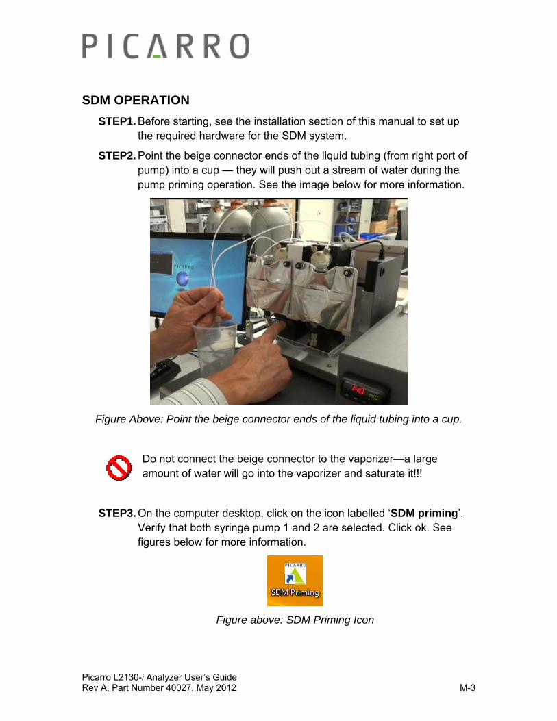
Picarro L2130-i Analyzer User’s Guide Rev A, Part Number 40027, May 2012 M-3
SDM OPERATION
STEP1. Before starting, see the installation section of this manual to set up the required hardware for the SDM system.
STEP2. Point the beige connector ends of the liquid tubing (from right port of pump) into a cup — they will push out a stream of water during the pump priming operation. See the image below for more information.
Figure Above: Point the beige connector ends of the liquid tubing into a cup.
Do not connect the beige connector to the vaporizer—a large amount of water will go into the vaporizer and saturate it!!!
STEP3. On the computer desktop, click on the icon labelled ‘SDM priming’. Verify that both syringe pump 1 and 2 are selected. Click ok. See figures below for more information.
Figure above: SDM Priming Icon
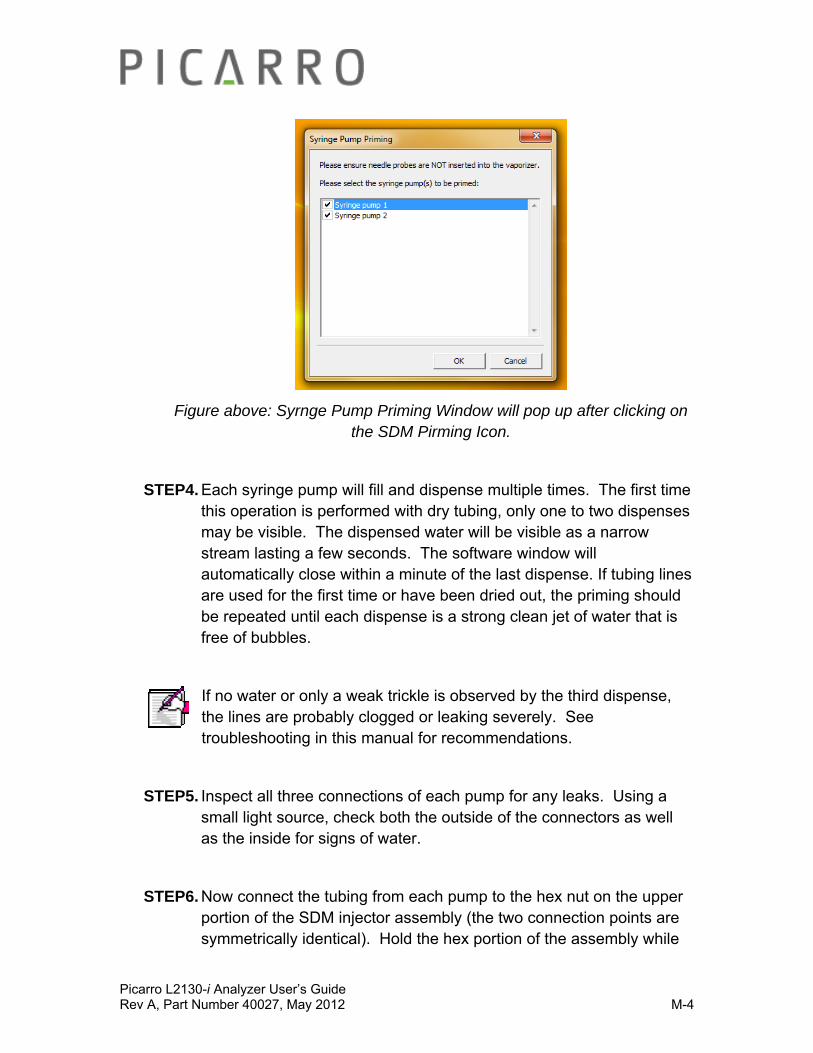
Picarro L2130-i Analyzer User’s Guide Rev A, Part Number 40027, May 2012 M-4
Figure above: Syrnge Pump Priming Window will pop up after clicking on the SDM Pirming Icon.
STEP4. Each syringe pump will fill and dispense multiple times. The first time this operation is performed with dry tubing, only one to two dispenses may be visible. The dispensed water will be visible as a narrow stream lasting a few seconds. The software window will automatically close within a minute of the last dispense. If tubing lines are used for the first time or have been dried out, the priming should be repeated until each dispense is a strong clean jet of water that is free of bubbles.
If no water or only a weak trickle is observed by the third dispense, the lines are probably clogged or leaking severely. See troubleshooting in this manual for recommendations.
STEP5. Inspect all three connections of each pump for any leaks. Using a small light source, check both the outside of the connectors as well as the inside for signs of water.
STEP6. Now connect the tubing from each pump to the hex nut on the upper portion of the SDM injector assembly (the two connection points are symmetrically identical). Hold the hex portion of the assembly while
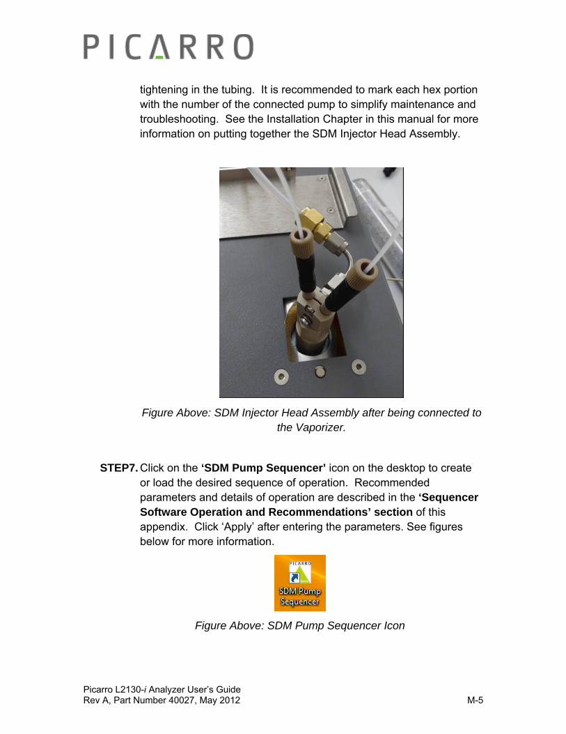
Picarro L2130-i Analyzer User’s Guide Rev A, Part Number 40027, May 2012 M-5
tightening in the tubing. It is recommended to mark each hex portion with the number of the connected pump to simplify maintenance and troubleshooting. See the Installation Chapter in this manual for more information on putting together the SDM Injector Head Assembly.
Figure Above: SDM Injector Head Assembly after being connected to the Vaporizer.
STEP7. Click on the ‘SDM Pump Sequencer’ icon on the desktop to create or load the desired sequence of operation. Recommended parameters and details of operation are described in the ‘Sequencer Software Operation and Recommendations’ section of this appendix. Click ‘Apply’ after entering the parameters. See figures below for more information.
Figure Above: SDM Pump Sequencer Icon

Picarro L2130-i Analyzer User’s Guide Rev A, Part Number 40027, May 2012 M-6
Figure Above: ‘Syringe Pump Sequence Setup’ window will pop up after clicking on the SDM pump Sequencer Icon.
STEP8. On the computer desktop, click on the icon labelled ‘Coordinator Launcher’. Select ‘standards delivery module/SDM’ from the pull down list on the ‘Picarro Coordinator Launcher’ Window, and then click ‘Launch’. Enter the names of the liquid standards on the ‘user editable parameters’ window and then click ‘ok’ to continue. The applied sequence will now start. More details of operation are given in the ‘SDM Coordinator description section’ of this appendix. Also see figures below for more information.
Figure Above: Coordinator Launcher Icon
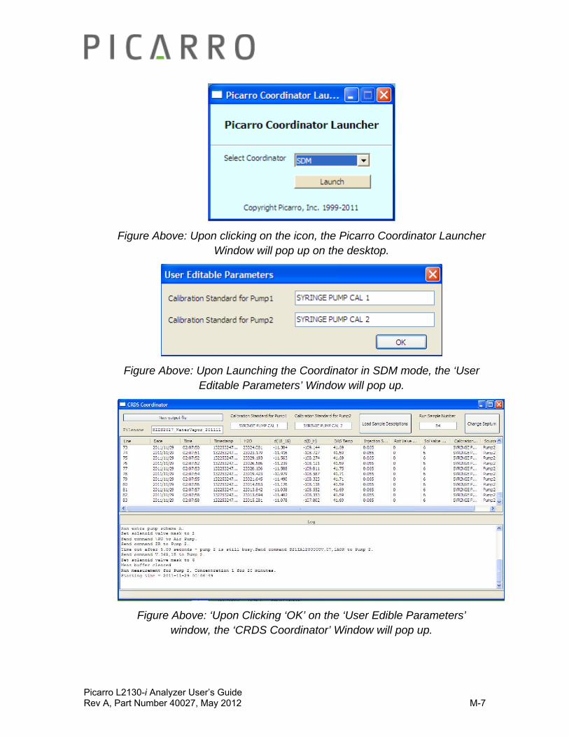
Picarro L2130-i Analyzer User’s Guide Rev A, Part Number 40027, May 2012 M-7
Figure Above: Upon clicking on the icon, the Picarro Coordinator Launcher Window will pop up on the desktop.
Figure Above: Upon Launching the Coordinator in SDM mode, the ‘User Editable Parameters’ Window will pop up.
Figure Above: ‘Upon Clicking ‘OK’ on the ‘User Edible Parameters’ window, the ‘CRDS Coordinator’ Window will pop up.
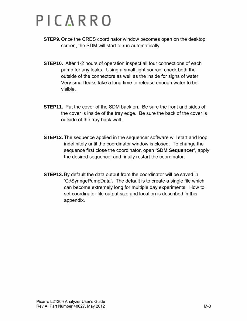
Picarro L2130-i Analyzer User’s Guide Rev A, Part Number 40027, May 2012 M-8
STEP9. Once the CRDS coordinator window becomes open on the desktop screen, the SDM will start to run automatically.
STEP10. After 1-2 hours of operation inspect all four connections of each pump for any leaks. Using a small light source, check both the outside of the connectors as well as the inside for signs of water. Very small leaks take a long time to release enough water to be visible.
STEP11. Put the cover of the SDM back on. Be sure the front and sides of the cover is inside of the tray edge. Be sure the back of the cover is outside of the tray back wall.
STEP12. The sequence applied in the sequencer software will start and loop indefinitely until the coordinator window is closed. To change the sequence first close the coordinator, open ‘SDM Sequencer’, apply the desired sequence, and finally restart the coordinator.
STEP13. By default the data output from the coordinator will be saved in ‘C:\SyringePumpData’. The default is to create a single file which can become extremely long for multiple day experiments. How to set coordinator file output size and location is described in this appendix.
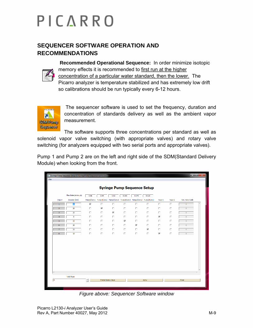
Picarro L2130-i Analyzer User’s Guide Rev A, Part Number 40027, May 2012 M-9
SEQUENCER SOFTWARE OPERATION AND RECOMMENDATIONS
Recommended Operational Sequence: In order minimize isotopic memory effects it is recommended to first run at the higher concentration of a particular water standard, then the lower. The Picarro analyzer is temperature stabilized and has extremely low drift so calibrations should be run typically every 6-12 hours.
The sequencer software is used to set the frequency, duration and concentration of standards delivery as well as the ambient vapor measurement.
The software supports three concentrations per standard as well as solenoid vapor valve switching (with appropriate valves) and rotary valve switching (for analyzers equipped with two serial ports and appropriate valves).
Pump 1 and Pump 2 are on the left and right side of the SDM(Standard Delivery Module) when looking from the front.
Figure above: Sequencer Software window
Picarro L2130-i Analyzer User’s Guide Rev A, Part Number 40027, May 2012 M-10
The Concentration of Vapor: This will be determined by the user programmed liquid flow rate. A rate of 0.02 microliters/second corresponds to approximately 6000ppmv. The vapor concentration is a linear function of the liquid flow rate. Rates higher than 0.08 microliters/second (24000ppmv) are prevented by the software in order to prevent accidental saturation of the analyzer.
The precision of the isotopic ratio measurement is specified for a vapor concentration of 6000 to 20000ppmv. The precision will suffer significantly below 6000ppmv. Increasing the measurement duration will compensate to some degree. The dry air source, such as Drierite® condition air with a 200-300ppmv water concentration, can contribute significantly to the measured isotope rate when operating at standard vapor concentrations below 6000ppmv.
For each step in the sequence only one pump or vapor state is allowed. If enabled, the rotary valve position is always active.
Vapor 1 State: Allows the analyzer to pull air through the connector labelled ‘Sample 2’ on the back of the vaporizer. No power is supplied to any solenoid valve in this state. For analyzers with an additional valve (carrying V4 gas) also connected to the ‘Sample 2,’ air will be drawn through the NO port of the valve.
Vapor 2 State: In this state, power IS applied to the solenoid valve connected to the wire pair labelled V4. For analyzers with an additional valve(carrying V4 gas) also connected to the ‘Sample 2’, V4 gas will be drawn through the NC port of that valve.
Rotary Valve Position: This is controlled independently of the liquid pumps and solenoid valves. The default value is ‘0’ which is generally not a valid position. This prevents the rotary valve from inadvertently switching to a new position.
The common line of the rotary valve can be connected to ‘Sample 2’ on the back of the vaporizer. Whenever ‘Vapor 1’ is selected in the software, sample will be drawn through the common line and whichever rotary valve position is selected.

Picarro L2130-i Analyzer User’s Guide Rev A, Part Number 40027, May 2012 M-11
By specifying Vapor 1 State, Vapor 2 State, or the Rotary Valve Position on the Sequencer Software window, it is possible to sample air from multiple locations for one experiment sequence.

Picarro L2130-i Analyzer User’s Guide Rev A, Part Number 40027, May 2012 M-12
SDM COORDINATOR
Upon choosing the SDM mode on the SDM ‘Coordinator Launcher’ window, the software prompt will ask for the names of the two liquid standards. You will see the following window.
After the names are entered or default is accepted, the coordinator software will start to run the active sequence (previously applied using the syringe pump sequencer software). The sequence will run in a loop until cancelled by the user.
Below are descriptions of the Coordinator Window.
1. UPPER PORTION OF THE WINDOW: The upper table in the coordinator window will display measured values from the analyzer (In columns – line, date, time, etc…).
Picarro L2130-i Analyzer User’s Guide Rev A, Part Number 40027, May 2012 M-13
2. LOWER PORTION OF THE WINDOW (Log): The coordinator software will display a log of operational steps and commands. The current step will be at the very bottom of the log. To view the overall sequence of operation, open the ‘syringe pump sequencer software’. If the sequence has been modified the currently used sequence can be reloaded from the file ‘active.seq’.
3. NEW OUTPUT FILE: This button can be clicked to change the file name or to create a new file. Select the ‘new output file’ button and enter a new name. By default the data will be stored in a single *.csv file- see the rest of this Appendix for information on how to change this or the default directory for file saving.
4. X-BUTTON: To stop the coordinator, click on the ‘x’ in the upper right corner of the coordinator window.
5. LOAD SAMPLE DESCRIPTIONS: This has no function in the SDM mode.
6. CHANGE SEPTUM: This has no function in the SDM mode.
Below are descriptions about the data files.
1. LOCATION OF THE DATA FILE: The coordinator will automatically create a *.csv file containing the measured values. The file will be saved in the directory C:\SyringePumpData\ under the date and time when the coordinator was started.
2. HOW TO READ THE DATA FILE: The *.csv file can be read using Notepad++ which is provided on the Picarro CPVU (Computer Power Vacuum Unit).

Picarro L2130-i Analyzer User’s Guide Rev A, Part Number 40027, May 2012 M-14
DATA PROCESSING
The SDM includes data processing software for user convenience. To start the software, double click on the icon ‘SDM Data Processor’ on the desktop. The ‘Syringe Pump Data Processor’ window will pop up on your desktop. See figures below.
Figure Above: SDM Data Processor icon on the desktop
Figure Above: The ‘Syringe Pump Data Processor’ Window will pop up upon clicking on the ‘SDM Data Processor’ icon on the desktop.Refer to this image
while reading the rest of this section.
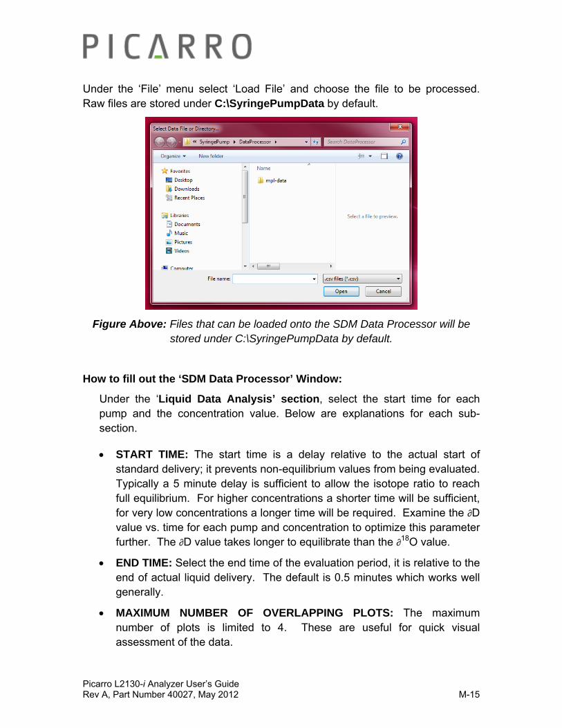
Picarro L2130-i Analyzer User’s Guide Rev A, Part Number 40027, May 2012 M-15
Under the ‘File’ menu select ‘Load File’ and choose the file to be processed. Raw files are stored under C:\SyringePumpData by default.
Figure Above: Files that can be loaded onto the SDM Data Processor will be stored under C:\SyringePumpData by default.
How to fill out the ‘SDM Data Processor’ Window:
Under the ‘Liquid Data Analysis’ section, select the start time for each pump and the concentration value. Below are explanations for each sub-section.
START TIME: The start time is a delay relative to the actual start of standard delivery; it prevents non-equilibrium values from being evaluated. Typically a 5 minute delay is sufficient to allow the isotope ratio to reach full equilibrium. For higher concentrations a shorter time will be sufficient, for very low concentrations a longer time will be required. Examine the ∂D value vs. time for each pump and concentration to optimize this parameter further. The ∂D value takes longer to equilibrate than the ∂18O value.
END TIME: Select the end time of the evaluation period, it is relative to the end of actual liquid delivery. The default is 0.5 minutes which works well generally.
MAXIMUM NUMBER OF OVERLAPPING PLOTS: The maximum number of plots is limited to 4. These are useful for quick visual assessment of the data.

Picarro L2130-i Analyzer User’s Guide Rev A, Part Number 40027, May 2012 M-16
THE PROCESS BUTTON: The process button in the upper right will process the data for liquid data analysis only. The data will automatically have a 30 second moving average applied to it.
Under the Vapor Data Analysis section select the start and end times in the same fashion as for the liquid data analysis. Below are explanations for each sub-section.
START TIME: The start time delay required for vapor may be significantly larger than for liquid data. This is due to concentration effects as well due to the absence of preconditioning steps for vapor analysis. The averaging window size applies a moving average to the vapor data.
PROCESS BUTTON: The process button in the middle right will process the data for vapor data analysis only.
PROCESS BUTTON: To process the data for both liquid and vapour, press the process button at the very bottom of the window.
Where to find the processed data:
Once data is processed one or more files are generated. They are all stored in C:\SyringePumpData\ProcessedData by default. The processed data is saved in *.csv format and can be viewed by double clicking on the blue hyperlinks shown in the Data Processor window. Each hyperlink has text above it describing the contents of the processed file.
High Standard Deviation?
If the reported standard deviations (SD) appear high for any particular standard delivery note the time and view the H2O concentration for that period. There may be a specific upset such as an air bubble that can be excluded from the data processing by changes in the start/end time. If there is significant oscillation in the water concentration (amplitude >250ppmv) that is an indication of uneven water delivery which is generally caused by loose connections, partially clogged lines/needles, or an air bubble undergoing compression/relaxation as it is pumped through the line.
Picarro L2130-i Analyzer User’s Guide Rev A, Part Number 40027, May 2012 M-17
SETTING COORDINATOR FILE OUTPUT SIZE AND LOCATION
By default there is no upper limit on the size of the coordinator file output. When the SDM is run for prolonged periods the size of the generated *.csv file will become very large and easily exceed 65536 records which is the upper limit of MS Excel. A new record is generated with each scan reported by the analyzer, the scan time ranges from 5-10 seconds depend upon analyzer configuration.
To limit the size of the output file:
Step 1: Open PicarroSyringePumpCoordinatorV13.ini file
Step 2: Use Notepad++ text editor (right click on file)
Step 3: Under section marked [FILES] at line 8 the default will be: max_num_lines=
Step 4: If it is left blank after the equals sign then there is no size limit
Step 5: To specify a limit on the number of records enter an integer value after the equals sign. For example: max_num_lines=2000
This will limit the file to 2000 records, the coordinator software will automatically create a new file when the 2000 record limit is reached.
Changing the location of the output file:
Step 1: Open PicarroSyringePumpCoordinatorV13.ini file
Step 2: Use Notepad++ text editor (right click on file)
Step 3: Under section marked [FILES] at line 7 the default will be: output=‘C:\SyringePumpData\’
Step 4: create a new location by changing the value in ‘ ’.
for example output=‘C:\MyDocuments\SyringePumpData\’
This would save the outputs in a separate directory.
Picarro L2130-i Analyzer User’s Guide Rev A, Part Number 40027, May 2012 M-18
AUTOMATIC VAPORIZER PRECONDITIONING BY SDM
The SDM has certain pre-programmed operational steps which bring the vaporizer into isotopic equilibrium in a quick and consistent fashion to minimize time required for standards measurement and to simplify data analysis. These steps are in addition to the user entered sequence. There are different situations when this occurs:
Case A: Vapor to Standard
o Step 1: vapor measurement
o Step 2: water standard from pump 1 or 2
3.5 minutes before the end of step 1, the SDM delivers 6 microliters of water over 2.5 minutes followed by 1 minute at the user specified rate. The exit valve of the vaporizer vents this standard vapor out to the atmosphere. Once Step 2 starts, the valve connecting vaporizer to analyzer is opened allowing a nearly seamless transition between measuring the ambient vapor and standard vapor.
In the event the vapor measurement period is <3.5 minutes, the vapor measurement period is automatically extended (i.e. if the sequence call for a 1 minute vapor measurement then measurement of a standard the actual vapor measurement period will be 4.5 minutes.).
Case B: Between Two Standards
o Step 1: water standard from pump 1 or 2
o Step 2: water standard from pump 2 or 1
After step 1 is complete the SDM delivers 6 microliters from the following standard over 2.5 minutes followed by 1 minute at the user specified rate. The standard vapor from this automatic step is sent into the analyzer for measurement. When using the analysis software the 3.5 minute automatic step is automatically skipped over by the analysis software.
Case C: Between Two Concentrations
o Step 1: pump 1 conc. 1
o Step 2: pump 1 conc. 2
Syringe pump is refilled at the start of step 2 and then starts to dispense at the user specified rate.
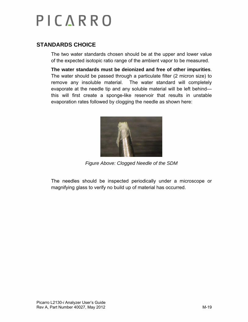
Picarro L2130-i Analyzer User’s Guide Rev A, Part Number 40027, May 2012 M-19
STANDARDS CHOICE
The two water standards chosen should be at the upper and lower value of the expected isotopic ratio range of the ambient vapor to be measured.
The water standards must be deionized and free of other impurities. The water should be passed through a particulate filter (2 micron size) to remove any insoluble material. The water standard will completely evaporate at the needle tip and any soluble material will be left behind—this will first create a sponge-like reservoir that results in unstable evaporation rates followed by clogging the needle as shown here:
Figure Above: Clogged Needle of the SDM
The needles should be inspected periodically under a microscope or magnifying glass to verify no build up of material has occurred.

Picarro L2130-i Analyzer User’s Guide Rev A, Part Number 40027, May 2012 M-20
BAG FILLING
The bag has a Luer-lock connector with a 10-32 female thread adapter attached to it, and it holds approximately 45mL of water. Restek Ice Blue silicone septa, 9mm in diameter, are provided with the bags. To fill the bag, see the images below.
Step 1: First seal the bottom connector on the bag with the supplied black plugs.
Step 2: Unscrew the metal cap on top and remove the blue septa.
Step 3: Fill the bag until nearly full. Fill until the water reaches the top of the metal fitting.

Picarro L2130-i Analyzer User’s Guide Rev A, Part Number 40027, May 2012 M-21
Step 4: Pull at the bag edges and/or tap the bag on the side to release trapped air.
Step 5: Press the bag gently upward to form a water layer on the top. Afterwards, press in the blue septa (some water should leak out), and screw on metal cap.
Step 6: Shake bag—if there is a significant noise then there is a lot of entrapped air—pull bag edges and fill again to remove as much air as possible.
Air can become trapped in the lower portion of the bag and be pulled into the pump lines—this will affect standards delivery. Always fill the bag as much as possible initially and pull on the bag edges before running the SDM.
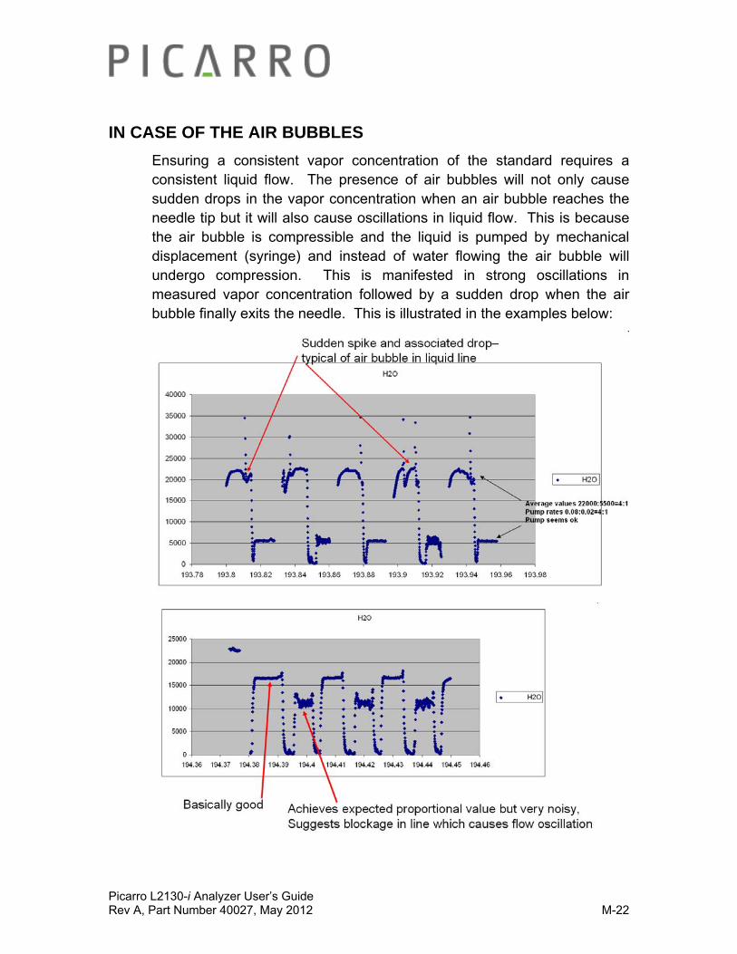
Picarro L2130-i Analyzer User’s Guide Rev A, Part Number 40027, May 2012 M-22
IN CASE OF THE AIR BUBBLES
Ensuring a consistent vapor concentration of the standard requires a consistent liquid flow. The presence of air bubbles will not only cause sudden drops in the vapor concentration when an air bubble reaches the needle tip but it will also cause oscillations in liquid flow. This is because the air bubble is compressible and the liquid is pumped by mechanical displacement (syringe) and instead of water flowing the air bubble will undergo compression. This is manifested in strong oscillations in measured vapor concentration followed by a sudden drop when the air bubble finally exits the needle. This is illustrated in the examples below:
Picarro L2130-i Analyzer User’s Guide Rev A, Part Number 40027, May 2012 M-23
FILED DEPLOYMENT TIP
Run the SDM in the lab to become fully familiar with its setup and operation before undertaking a field deployment.
Plan enough time for setup. Although the SDM sets up quickly it requires 2-4 hours of run time to fully verify performance so it can be left to run unattended. Plan on at least a half day, overnight is ideal. Ideally the SDM can be set up first and allowed to run while other equipment is being set up.
Be prepared. The bags should be filled in the laboratory. Extra lines and needles should be packed as well.
Don’t take shortcuts. The procedures in the manual are based on personal, sometimes painful, experiences gained by engineers and scientists during the development of the SDM. The effort of a proper setup will be rewarded by weeks of smooth unattended operation and good data.
Picarro L2130-i Analyzer User’s Guide Rev A, Part Number 40027, May 2012 M-24
ROTARY VALVE USE
The rotary valve control should be connected to COM 2 and the ‘Enable Rotary Valve Control’ button selected in the syringe pump sequencer software in order to make use of this functionality. Please contact Picarro for further details.
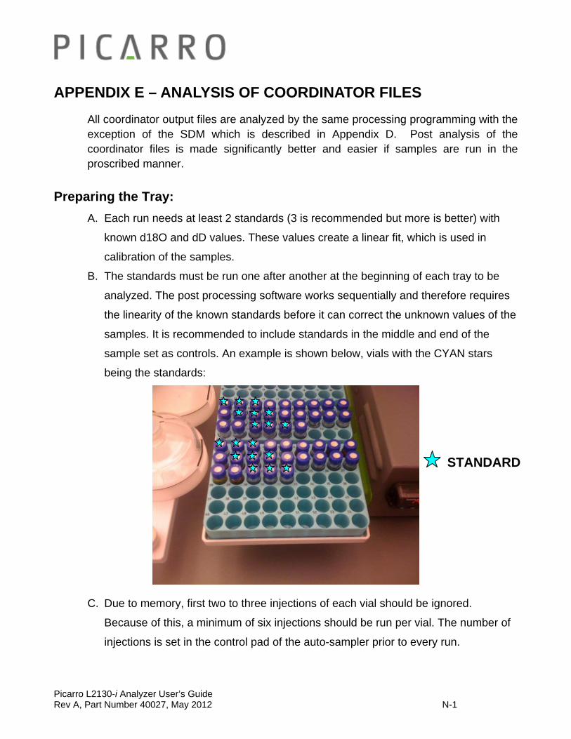
Picarro L2130-i Analyzer User’s Guide Rev A, Part Number 40027, May 2012 N-1
APPENDIX E – ANALYSIS OF COORDINATOR FILES
All coordinator output files are analyzed by the same processing programming with the exception of the SDM which is described in Appendix D. Post analysis of the coordinator files is made significantly better and easier if samples are run in the proscribed manner.
Preparing the Tray:
A. Each run needs at least 2 standards (3 is recommended but more is better) with
known d18O and dD values. These values create a linear fit, which is used in
calibration of the samples.
B. The standards must be run one after another at the beginning of each tray to be
analyzed. The post processing software works sequentially and therefore requires
the linearity of the known standards before it can correct the unknown values of the
samples. It is recommended to include standards in the middle and end of the
sample set as controls. An example is shown below, vials with the CYAN stars
being the standards:
C. Due to memory, first two to three injections of each vial should be ignored.
Because of this, a minimum of six injections should be run per vial. The number of
injections is set in the control pad of the auto-sampler prior to every run.
STANDARD
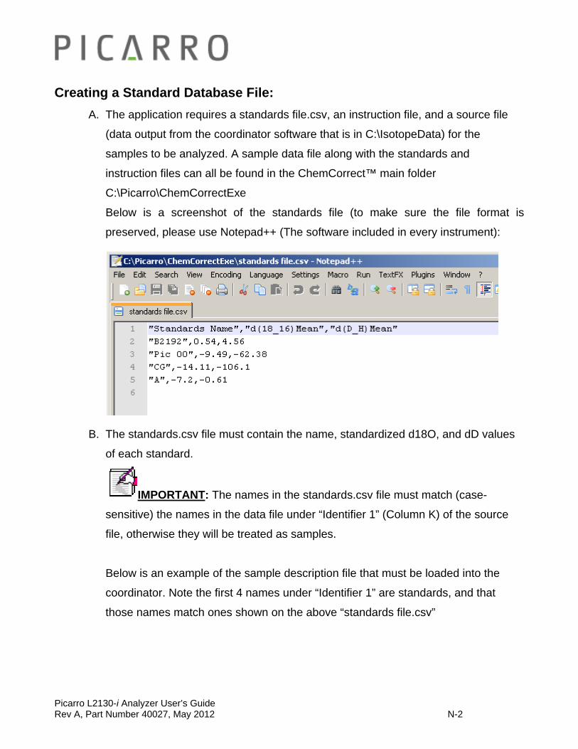
Picarro L2130-i Analyzer User’s Guide Rev A, Part Number 40027, May 2012 N-2
Creating a Standard Database File:
A. The application requires a standards file.csv, an instruction file, and a source file
(data output from the coordinator software that is in C:\IsotopeData) for the
samples to be analyzed. A sample data file along with the standards and
instruction files can all be found in the ChemCorrect™ main folder
C:\Picarro\ChemCorrectExe
Below is a screenshot of the standards file (to make sure the file format is
preserved, please use Notepad++ (The software included in every instrument):
B. The standards.csv file must contain the name, standardized d18O, and dD values
of each standard.
IMPORTANT: The names in the standards.csv file must match (case-
sensitive) the names in the data file under “Identifier 1” (Column K) of the source
file, otherwise they will be treated as samples.
Below is an example of the sample description file that must be loaded into the
coordinator. Note the first 4 names under “Identifier 1” are standards, and that
those names match ones shown on the above “standards file.csv”

Picarro L2130-i Analyzer User’s Guide Rev A, Part Number 40027, May 2012 N-3
Running the Post Processing:
A. There should be an icon on the desktop, to open, double-click on that icon. If icon
not available, the executable file for ChemCorrect™, “chemcorrect.exe,” is
contained in the main folder. To open it, either double-click “chemcorrect.exe” or
right-click it and select “Open.”
B. The top 4 boxes on the GUI are the required fields for ChemCorrect™ to operate:
the most recent source file name (sometimes empty), instruction file name,
standards file (contain a library of the standards’ isotope values) and number of
injections to be ignored. You have an option to plot additional graphs for other
parameters but those are just additional features.

Picarro L2130-i Analyzer User’s Guide Rev A, Part Number 40027, May 2012 N-4
C. To choose a different source file to be analyzed, click the “Source” button at the
bottom right. Then use the finder window to locate the desired raw data file and
click “Open.”
D. To select a different instruction file than the one displayed, click the “Instruction
Set” button. Then use the finder window to locate the desired instruction file and
click “Open”. See section K for a list of available instruction sets.
E. To change the number of injections to be ignored, highlight the existing number
and type in the preferred one (required 2 but 3 is recommended).
F. When the correct source and instruction files are shown, click the “Ok” button at the
bottom of the window to cue ChemCorrect™ to begin analysis.

Picarro L2130-i Analyzer User’s Guide Rev A, Part Number 40027, May 2012 N-5
Example Analysis:
A. Select “HBDS01_IsoWater_20100604_180843.csv” (which Picarro has provided in
the main folder) as the source, and “chemcorrect_inst avg_orgeval_06.csv” as the
instruction file. Then click “Ok.”
B. The first display is called the “Summary.” Contained here are: the calibrated
isotope values and visual indicators as to the severity of contamination by sample.
i. The CYAN colored rows are standards.
ii. The GREEN colored rows are samples that have been determined
to have little to no contamination.
iii. The YELLOW colored rows are samples that contain trace values of
contamination that may slightly shift the isotope values.
iv. The RED colored rows are samples with severe contamination
leading to inaccurate dD and d18O readings.
v. A star next to a sample indicates a problem, e.g. missing rows in
the source file resulting in an inaccurate calculation.
The color code legend is also available at the end of the summary tab.
CCYYAANN- Standard
GGRREEEENN- Clean
YYYEEELLLLLLOOOWWW- Some Contamination
RREEDD- Substantial Contamination

Picarro L2130-i Analyzer User’s Guide Rev A, Part Number 40027, May 2012 N-6
C. Red/yellow rows display relative contamination due to methane, methanol, or
“other” hydrocarbons in the respective columns on the right.
D. There are other tabs that can be accessed by clicking on them in the top left corner
of the window.
i. Detail- Summons a list of summarized charts by injection and
sample chronologically. The un-calibrated and calibrated values, as
well as the measurements taken to calibrate the values are included
per injection. Below each chart is a summary.
ii. Source- Displays the original raw data file without any changes or
calibration.
iii. Instructions- Displays the raw instruction file used by
ChemCorrect™ as well as comments on the far right of each
instruction.
iv. Additional plots for your convenience.
E. At the bottom of the ChemCorrect™ window are additional buttons “OK”, “Export
Spreadsheet,” and “Exit” buttons.
i. OK- each time you reloaded the source and instruction sets, you
can click “OK” again to process more data without closing and re-
opening ChemCorrect™. Once you make your edits, export the
result to save your processed data. See below
ii. Export Spreadsheet- Creates an excel spreadsheet complete with
all the information contained in the four tabs in the ChemCorrect™
main window as well as all the data sets and formulas used to
calibrate the isotope values.
iii. Exit- Quits ChemCorrect™.
F. The standards.csv file can be amended if needed, but the format must remain the
same. To edit, simply open the file, make the desired changes, and hit save. For
the changes to be reflected in ChemCorrect™, hit the “OK” button at the bottom of
the ChemCorrect™ GUI.
Picarro L2130-i Analyzer User’s Guide Rev A, Part Number 40027, May 2012 N-7
G. Picarro has provided 3 instruction files. Rather than being instructions for the user,
ChemCorrect™ uses them to calibrate values and flag for contaminants:
i. “chemcorrect_inst avg_01.csv”- Averages and calibrates isotopic
values according to the preceded standards.
ii. “chemcorrect_inst avg_mem_01.csv”- Same as above with an
added memory correction.
iii. “chemcorrect_inst avg_orgeval_06.csv”- Averages and calibrates
according to the preceded standards and flags for organic
contamination.
H. Each instruction file can be edited to perform your required calculations – for more
advanced users. In the provided instruction sets, Column C of each provides a
description of each operation. To edit an instruction file, follow the guidelines
outlined at the bottom of the instruction set file.
Important Notes:
It is highly recommended to run the post processing within 7 days of initially acquiring the data. If a sample is flagged as contaminated the post processing software will automatically set aside the associated spectral files. These files can be sent to Picarro for further analysis and spectral library development. Once set aside these files will not be affected by the automatic file management software which is running on the analyzer.
Due to the large amount of data generated by the analyzer a buffer of 10GB of spectral files are kept, after which point they are erased. This corresponds to approximately 2 weeks of operation. Running the post processing ensures that any spectra associated with contamination are not erased.
Picarro L2130-i Analyzer User’s Guide Rev A, Part Number 40027, May 2012 O-1
APPENDIX F - LIMITED WARRANTY
Picarro, Inc. warrants its Products to be free from defects in material and workmanship and to perform in the manner and under the conditions specified in the Product specifications for twelve (12) months from shipment.
This warranty is the only warranty made by Picarro with respect to its Products and no person is authorized to bind Picarro for any obligations or liabilities beyond this warranty in connection with its Products. This warranty is made to the original Purchaser only, is nontransferable and may only be modified or amended by a written instrument signed by a duly authorized officer of Picarro. Sub-systems manufactured by other firms, but integrated into Picarro Products, are covered by the original manufacturer’s warranty and Picarro makes no warranty, express or implied, regarding such sub-systems. Products or parts thereof which are replaced or repaired under this warranty are warranted only for the remaining, un-expired portion of the original warranty period applicable to the specific Product replaced or repaired.
NOTE: DISCLAIMER THE FOREGOING WARRANTY IS EXCLUSIVE AND IN LIEU OF ALL OTHER WARRANTIES WHETHER WRITTEN, ORAL OR IMPLIED, AND SHALL BE THE PURCHASER’S SOLE REMEDY AND PICARRO’S SOLE LIABILITY IN CONTRACT OR OTHERWISE FOR THE PRODUCT. PICARRO EXPRESSLY DISCLAIMS ANY WARRANTY OF MERCHANTABILITY OR FITNESS FOR A PARTICULAR PURPOSE. The Purchaser’s exclusive remedy with respect to any defective Product shall be to have Picarro repair or replace such defective Product or credit the Purchaser’s account, whichever Picarro may elect in its sole discretion. If it is found that any Product has been returned which is not defective, the Purchaser will be notified and such Product returned at the Purchaser’s expense. In addition, a charge for testing and examination may, at Picarro’s sole discretion, be made on any Product so returned.
These remedies are available only if: i) Picarro is notified in writing by the Purchaser promptly upon discovery of a Product defect, and in any event within the warranty period; ii) Picarro’s examination of such Product discloses to Picarro’s satisfaction that such defects actually exist and the Product has not been repaired, worked on, altered by persons not authorized by Picarro, subject to misuse, negligence or accident, or connected, installed, used or adjusted otherwise than in accordance with the instructions furnished by Picarro.
Picarro L2130-i Analyzer User’s Guide Rev A, Part Number 40027, May 2012 O-2
The following warranty conditions shall apply to all Picarro, Inc. products unless amended by a written instrument signed by a duly authorized officer of Picarro:
ADJUSTMENT – No electrical, mechanical or optical adjustments to the product(s) are permitted.
PARTS AND LABOR - New or factory-built replacements for defective parts will be supplied for twelve (12) months from date of shipment of the product. Replacement parts are warranted for the remaining portion of the original warranty period. There will be no charge for repair of products under warranty where the repair work is done by Picarro, Inc.
NOT COVERED BY THE WARRANTY – Damage to any optical surface from improper handling or cleaning procedures. This applies specifically to those items subjected to excess laser radiation, contaminated environments, extreme temperature or abrasive cleaning. Damage due to ESD, abuse, misuse, improper installation or application, alteration, accident, negligence in use, improper storage, transportation or handling. No warranty shall apply where the original equipment identifications have been removed, defaced, altered or where there is any evidence of alterations, adjustments, removal of protective outer enclosure, any attempt to repair the product by unauthorized personnel or with parts other than those provided by Picarro, Inc.
DAMAGE IN SHIPMENT - Your analyzer should be inspected and tested as soon as it is received. The product is packaged for safe delivery. If the product is damaged in any way, you should immediately file a claim with the carrier or, if insured separately, with the insurance company. Picarro, Inc. will not be responsible for damage sustained in shipment. All Picarro products are F.O.B. origin, shipped from the Picarro factory or Picarro distributor. The price of all Products, unless otherwise specifically stated, is Ex- Works, Sunnyvale, CA as defined by Incoterms, 2001. The cost of normal packaging for shipment is included in the invoiced price. Where Buyer specifies special packaging, a charge will be made to cover any extra expense.
CLAIMS ASSISTANCE - Call Picarro, Inc. Customer Service or your local distributor for assistance. Give our representative the full details of the problem. Helpful information or shipping instructions will be provided. If requested, estimates of the charges for non-warranty or other service work will be supplied before work begins.
Picarro L2130-i Analyzer User’s Guide Rev A, Part Number 40027, May 2012 O-3
RETURN PROCEDURE - Customers must obtain a Return Merchandise Authorization Number from Picarro, Inc. prior to returning units. Products being returned for repair must be shipped in their original shipping cartons to avoid damage.
CONTACT INFORMATION:
Website: www.picarro.com & www.picarro.com/community
Email: [email protected]
Phone: 408.962.3900 Fax: 408.962.3200
Address: 480 Oakmead Parkway
Sunnyvale, California CA 94085 USA.
Picarro, Inc. reserves the right to change or update the contents of this manual and to change the specifications of its products at any time without prior notification. Every effort has been made to keep the information in this document current and accurate as of the date of publication or revision. However, no guarantee is given or implied that this document is error free or that it is accurate with regard to any specification.
Picarro, Inc. has prepared this manual for use by its customers as a guide for the proper installation, operation and/or maintenance of the Picarro Analyzer.
Picarro and the Picarro Logo are trademarks of Picarro, Inc.
2011 Picarro, Inc. All rights reserved.

Picarro L2130-i Analyzer User’s Guide Rev A, Part Number 40027, May 2012 P-1
APPENDIX G-SERVICE AND MAINTENANCE
The advanced, rugged design of the Picarro Analyzers provides stable, long-term operation with minimal service or maintenance. With the exception of the particulate filter, the analyzer is not user serviceable.
Should it appear to malfunction, please refer to the Troubleshooting Guide, refer to the Community URL
(www.picarro.com/community), or contact Picarro.
Particulate Filter:
There are two in-line, sub-micron particulate filters before the measurement cavity. The first is user-replaceable and replacement filters can be purchased from Picarro and installed by the user. It is important to NEVER remove the filter that is directly attached to the cavity. Only change the filter immediately following the inlet at the back of the analyzer. Refer to the filter replacement procedure in this document for further details. The symptoms of a clogged filer can be analyzer reporting “pressure low” or there being no flow into the instrument, causing unusual measurements. Filters can become clogged after years of use in dirty environments. If liquid water is accidentally sucked into the inlet line, it will clog the filter and impede the flow (usually for a few days) until it evaporates. If this occurs, it is important to NOT turn off the analyzer or replace the filter until it is dry. The reason for this is that the increased humidity due to liquid water in the filter can cause condensation on the optics if the analyzer is allowed to cool from its operating temperature. Often, after the filter dries, the analyzer will begin functioning normally, and a filter replacement is not necessary.
Picarro Analyzer Replacement Procedure for User-Serviceable Particulate Filter
Tools Required:
o 1.5mm hex driver
o 9/16” open-end wrench
o 5/8” open-end wrench
o 11/16” open-end wrench
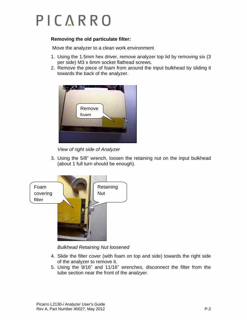
Picarro L2130-i Analyzer User’s Guide Rev A, Part Number 40027, May 2012 P-2
Removing the old particulate filter:
Move the analyzer to a clean work environment
1. Using the 1.5mm hex driver, remove analyzer top lid by removing six (3 per side) M3 x 6mm socket flathead screws.
2. Remove the piece of foam from around the input bulkhead by sliding it towards the back of the analyzer.
View of right side of Analyzer
3. Using the 5/8” wrench, loosen the retaining nut on the input bulkhead (about 1 full turn should be enough).
Bulkhead Retaining Nut loosened
4. Slide the filter cover (with foam on top and side) towards the right side of the analyzer to remove it.
5. Using the 9/16” and 11/16” wrenches, disconnect the filter from the tube section near the front of the analzyer.
Remove foam
Foam covering filter
Retaining Nut
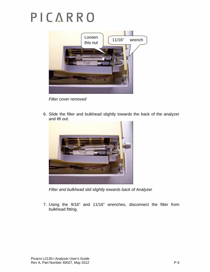
Picarro L2130-i Analyzer User’s Guide Rev A, Part Number 40027, May 2012 P-3
Filter cover removed
6. Slide the filter and bulkhead slightly towards the back of the analyzer and lift out.
Filter and bulkhead slid slightly towards back of Analyzer
7. Using the 9/16” and 11/16” wrenches, disconnect the filter from bulkhead fitting.
Loosen this nut
11/16” wrench

Picarro L2130-i Analyzer User’s Guide Rev A, Part Number 40027, May 2012 P-4
Filter removed and separated from bulkhead fitting
Installing the new filter:
1. Note: When re-attaching 1/4” Swagelok fittings, the nut should be hand-tightened and then turned an additional 1/8 of a turn using a wrench.
2. Using the 9/16” and 11/16” wrenches, remove the filter from its packaging and attach it to the bulkhead fitting. The arrow on the filter needs to point away from the bulkhead fitting.
3. Using the 9/16” and 11/16” wrenches, reposition the filter and bulkhead
fitting, and reattach to the tube section.
New filter attached to bulkhead fitting

Picarro L2130-i Analyzer User’s Guide Rev A, Part Number 40027, May 2012 P-5
4. Using the 5/8” wrench, reposition the filter cover and tighten the retaining nut on the bulkhead fitting. The metal edge of the filter cover should be under the foam of the top of the enclosure.
5. Reposition the piece of foam around the input bulkhead fitting.
6. With the 1.5mm hex driver, reattach the analyzer top with 3 screws on
each side.
Picarro L2130-i Analyzer User’s Guide Rev A, Part Number 40027, May 2012 Q-1
APPENDIX H - TROUBLESHOOTING
The following section lists problems that may be encountered during installation and operation of the analyzer. The corresponding step-by-step procedures provide resolution in most cases. If, after attempting these procedures, the problem remains unresolved, please contact Picarro Customer Service at (408) 962-3900 or [email protected].
More troubleshooting information is available at the www.picarro.com/community website.
1. Power LED on analyzer does not illuminate
Context: Turning on the analyzer by momentarily depressing its front panel power switch should apply power. The green power LED is illuminated when it detects the correct power levels.
(a) Check that the AC power cord is attached and plugged into a working outlet.
(b) Check that the rear on-off switch near the AC power cord is in the on position.
(c) Press and hold the front panel power switch for at least 5 seconds as the analyzer may take several seconds to respond.
2. User interface program does not start
Context: The computer may be configured to start the instrument and the associated user interface program automatically after it completes its boot-up sequence, or the program may be launched using the “Start instrument” icon on thetop.
(a) Communications problems with the analyzer may occur if the analyzer fails to initialize correctly on power up. Should the analyzer initialization process not complete correctly, shut down the instrument by shutting down the Windows operating system on the control computer: use the Start menu, select the red Shut down button and select “Shut down” in the drop-down box under “What do you want the computer to do?”. Wait for the shutdown to complete normally and for the computer and analyzer to turn off completely. After a few seconds, restart the computer by momentarily depressing the power button.

Picarro L2130-i Analyzer User’s Guide Rev A, Part Number 40027, May 2012 Q-2
Note: Do not simply restart Windows, since this does not cycle the power to the analyzer.
3. Sample pressure cannot be controlled to the appropriate value for concentration measurements
Context: Under normal operation, the cavity pressure is automatically locked to the correct value by means of electronically controlled inlet and outlet valves. The message “Pressure Locked” on the front panel display and the user interface indicates that the cavity pressure is at the appropriate value. Should either of the messages “Pressure high” or “Pressure low” be displayed, the cavity pressure is out of its correct operating range.
a) The “Pressure low” message indicates that there is insufficient gas available at the inlet of the analyzer. Check the inlet plumbing to the analyzer and ensure that the pressure at the inlet is within the specifications.
b) The “Pressure high” message indicates that gas cannot be removed from the analyzer at a sufficient rate. Check the vacuum line between the analyzer and the power vacuum unit for leaks. Failure of the vacuum pump, injecting dilution gas at excessive pressure, or excessive pressure at the inlet can also cause this problem.
4. User interface program “freezes” and does not update graphs as data are collected
Context: The computer may become unresponsive causing the programs that control the analyzer to stop functioning. The computer and analyzer should be shut down and restarted.
a) Re-setting the computer and the instrument requires that the computer be shut down and restarted. If the computer responds to the mouse, a normal Windows shutdown may be carried out: use the Start menu, select the red Shut down button and select “Shut down” in the drop-down box under “What do you want the computer to do?” Wait for the shutdown to complete normally and for the computer and analyzer to turn off completely. After a few seconds, restart the computer by momentarily depressing the power button.
Picarro L2130-i Analyzer User’s Guide Rev A, Part Number 40027, May 2012 Q-3
b) If the computer does not respond to the mouse, hold down the power switch on the front panel for a few seconds until the computer and the instrument turn off. After another few seconds, restart the analyzer by momentarily depressing the power button.
The following section lists solutions to a common problem that may be encountered while using the ChemCorrect Sotware.
1. My ChemCorrect Processing Software hung up (froze).
a) Check that you ran the correct coordinator: Ones with ChemCorrect in the name. The output csv file should contain columns with ORGANIC in the heading.
b) If the above checked out, the other usual cause is syntax error and/or missing/empty row(s) in the coordinator output file. The below 3 files are user-editable:
I. Instruction Set: C:\Picarro\ChemCorrectExe\chemcorrect_inst xx.csv
II. Standard Library: C:\Picarro\ChemCorrectExe\standards file.csv
III. Coordinator Output csv file or source file: HBDSxx _CC_IsoWater_xx.csv
c) The instruction set is usually not edited unless you’re an avid user. The standards file syntax is not too complicated to follow. The most common errors occur in the coordinator output file. These are the items to check:
I. The number of injections that you set ChemCorrect Analysis to ignore has to be less than the total injections/sample.
II. There can’t be any empty row or blank value (as a result of broken/bent needle, or sample ran out of liquid). This is not an issue if you have ChemCorrect version 1.2.0 or later.
III. “Line” column has to be sequential and start at 1
Picarro L2130-i Analyzer User’s Guide Rev A, Part Number 40027, May 2012 Q-4
IV. “Time Code” column has to be chronological.
V. Port number should correspond with the correct sample number.
VI. If you have to edit this source file, use Excel (an exception to all previous warnings to use Notepad++ because it's a lot easier but be careful). When done editing, close the file, when asked "Do you want to save changes...?", click "yes", when asked to keep the format, click "yes”. MS Excel 2007 should work fine and if you have trouble with other versions, let us know.
VII. Sometimes above syntax errors will crash ChemCorrect and you won't be able to run the software, instead an error message pops up with a path to the error log file. If this happens, please report this bug to help us improve our software. The temporary work around is to delete this file "chemcorrect.clt" in the ChemCorrectExe root directory.
The following section lists common problems that may be encountered while operating the SDM (Standard Delivery Module).
1. No communication between software and SDM.
(a) Verify power is on (LED in front). Verify COM 1 of analyzer is connected to SDM. Remove cover and check internal connections.
2. Water vapor concentration is unexpectedly very low (100-300ppmv) during standards measurement.
(a) Check water delivery pathway. Remove cover and disconnect tubing from problematic standard. Run priming software for that pump only (the movement of the syringe pump will be visible by looking from the side of the SDM, there will be 3 cycles). Assuming the pump is working and there is no water then one of the lines is clogged. If there is water then the problem is with
Picarro L2130-i Analyzer User’s Guide Rev A, Part Number 40027, May 2012 Q-5
the needle. Remove the needle from the injector assembly, connect to tubing and check again.
4. Water vapor concentration is unexpectedly high (20000+ ppmv) during standards measurement.
a) Verify the air pump is running. Verify there is a flow of about 250 sccm coming out of the vacuum port of the vaporizer. If both are operating correctly then excess water previously entered the vaporizer. Please contact Picarro for instructions on how to dry out the vaporizer. If the pump is running and air flow is <250 sccm then the line is leaking before the vaporizer or is blocked. Blockage most likely will occur at the orifice at the pump outlet. The pump inlet is equipped with a filter inlet to prevent particles from entering.
5. Standard deviation of standard isotope ratio exceeds typical values/water concentration during standards delivery shows large oscillations (250+ppmv) or erratic behaviour. Amplitude may be worse for lower concentrations.
a) Carefully look at tubing for bubbles. Disconnect tubing from needle and run priming—stream should be a strong narrow jet of water free of bubbles. Remove needle from injector assembly and check with microscope/10x magnifying glass for encrustations/blockage if priming jet is strong. If priming jet is weak disconnect and replace tubing. The pump can generate enough pressured to overcome a partial blockage at higher flow rates but not at lower flow rates. So if the same pump shows oscillation only at low flow rates it is very likely the problem is a partial blockage in the fluid pathway.
b) If priming jet contains bubbles and tubing connections are good then “palpate the bag”- i.e. pull at the edges, tap, etc …to detach air bubbles from outlet area so they can rise to the top. Good bag filling and line connection procedure minimizes this problem.

Picarro L2130-i Analyzer User’s Guide Rev A, Part Number 40027, May 2012 Q-6
3. Data displayed in coordinator or processed data files does not match column heading.
a) The analyzer has an earlier configuration file with a different order of columns. Please contact Picarro for assistance at at (408) 962-3900 or [email protected].
Picarro L2130-i Analyzer User’s Guide Rev A, Part Number 40027, May 2012 R-1
APPENDIX I - TRANSPORTATION AND STORAGE
In the event that the instrument will be transported or stored, the following procedure can be used to prepare the instrument and repack it into the original carton.
Packing the Analyzer:
1) Shutdown the instrument using the shutdown button using the “prepare for shipment” option. Clean dry gas should be attached to the instrument prior to shutting down. This prevents condensation inside the system during storage or shipment.
2) Disconnect all the tubing and electrical connections from the Analyzer.
3) To prevent contamination and possible damage to the connector
threads, place caps on all gas connections.
4) Place the analyzer in a plastic bag with a package of desiccant. Seal the bags with tape.
5) Pack the Analyzer in the original shipping container ensuring that
all of the foam pieces are in place to protect the Analyzer during shipping.
CAUTION: WHEN SHIPPING OR RELOCATING THE ANALYZER, IT IS IMPORTANT TO PROTECT IT FROM MECHANICAL SHOCKS. FAILURE TO DO SO CAN COMPROMISE ITS PERFORMANCE. WHEN SHIPPING THE ANALYZER, USE ITS ORIGINAL PACKAGING ONLY.

Picarro L2130-i Analyzer User’s Guide Rev A, Part Number 40027, May 2012 S-1
APPENDIX J - AUTOSAMPLER VAPORIZER A0212 INSTALLATION & TROUBLESHOOTING
After completing the Basic Analyzer Set Up (Installation chapter in L2130-i user manual), please follow the steps below to set up the Autosampler and
the High Throughput Vaporizer A0212.
1. Connect the Autosampler vertical legs to the XY Axis Stage of the Autosampler (See Fig 1): First use the T20 Torx driver (supplied) to loosen the screw on each mounting claw on the vertical legs until it moves freely. Insert the mounting claw in the rails of the X axis unit, holding in position while tightening the screw until the claw expands and engages tightly. The distance between the legs must be 17-17 ¼” (432-438 mm) to accommodate the Picarro analyzer. Measure 1 ⅞-2” (48-51mm) from inside edge of the leg to the very outer edge of the X Axis Stage. The ribbon cable access on the XY Axis Stage and the long length of each leg should point to the front.
Figure 1 – Showing orientation and position of legs for the Autosampler.
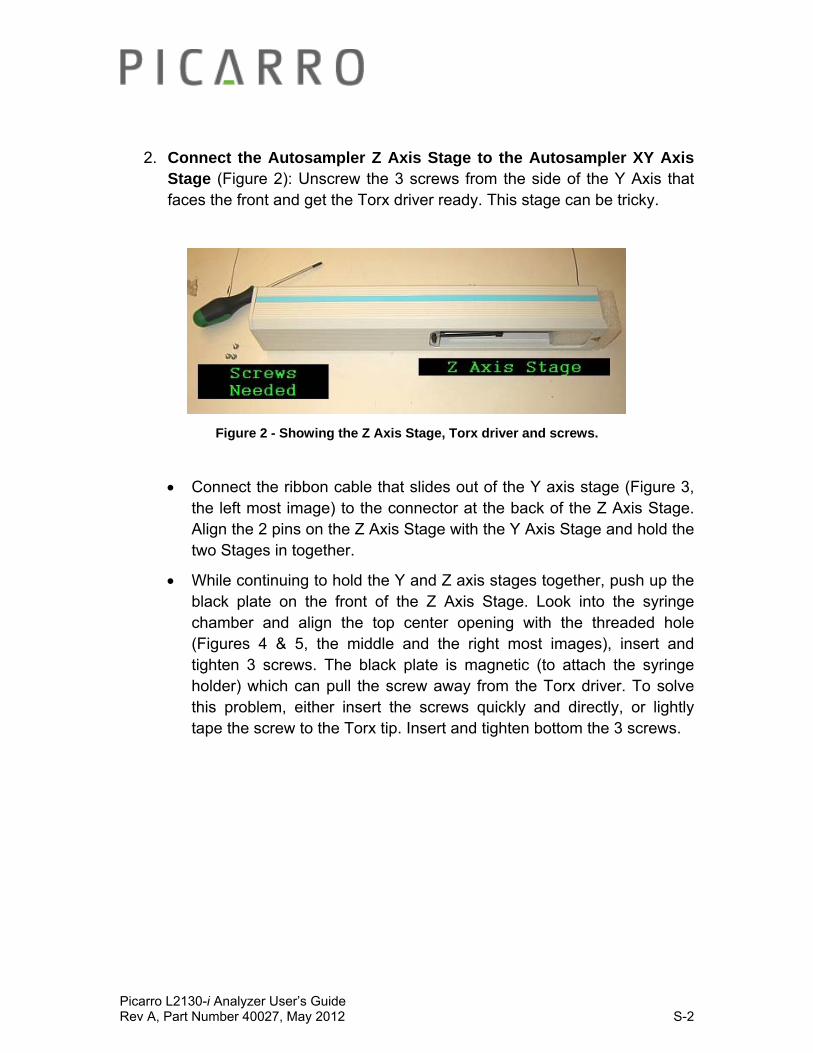
Picarro L2130-i Analyzer User’s Guide Rev A, Part Number 40027, May 2012 S-2
2. Connect the Autosampler Z Axis Stage to the Autosampler XY Axis Stage (Figure 2): Unscrew the 3 screws from the side of the Y Axis that faces the front and get the Torx driver ready. This stage can be tricky.
Figure 2 - Showing the Z Axis Stage, Torx driver and screws.
Connect the ribbon cable that slides out of the Y axis stage (Figure 3, the left most image) to the connector at the back of the Z Axis Stage. Align the 2 pins on the Z Axis Stage with the Y Axis Stage and hold the two Stages in together.
While continuing to hold the Y and Z axis stages together, push up the black plate on the front of the Z Axis Stage. Look into the syringe chamber and align the top center opening with the threaded hole (Figures 4 & 5, the middle and the right most images), insert and tighten 3 screws. The black plate is magnetic (to attach the syringe holder) which can pull the screw away from the Torx driver. To solve this problem, either insert the screws quickly and directly, or lightly tape the screw to the Torx tip. Insert and tighten bottom the 3 screws.

Picarro L2130-i Analyzer User’s Guide Rev A, Part Number 40027, May 2012 S-3
Figures 3, 4, 5 - From left to right: Connect the ribbon cable and align the two pins. Lift the black plate and look through the top central hole to align the threaded hole. Use the Torx
driver to push the screw through and tighten.
3. Attach blue syringe plate to black back plate (Figure 6.1, 6.2): It attaches magnetically and is aligned by 4 pins. Make sure to install it with the black syringe lock to the left of the groove for the syringe.
Figure 6.1 – Left: four pins align the syringe holder. Figure 6.2 – Right: ensure that holder is the right way up.
4. Connect the wash station and the tray holder to the Autosampler X Axis Stage (Figure 7.1, Figure 7.2): The inner edge of the wash station should be 4 ¾” (121 mm) from the outer edge of the X Axis Stage (not the leg). The inner edge of the tray holder arm closest to the wash station
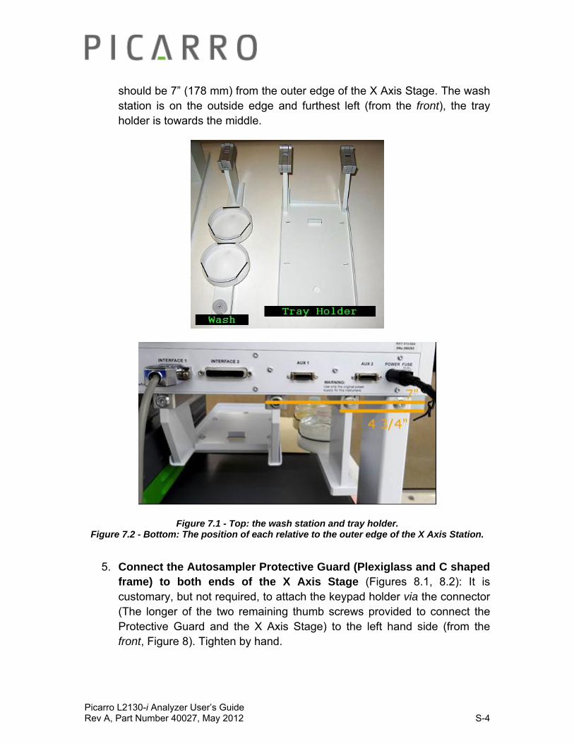
Picarro L2130-i Analyzer User’s Guide Rev A, Part Number 40027, May 2012 S-4
should be 7” (178 mm) from the outer edge of the X Axis Stage. The wash station is on the outside edge and furthest left (from the front), the tray holder is towards the middle.
Figure 7.1 - Top: the wash station and tray holder. Figure 7.2 - Bottom: The position of each relative to the outer edge of the X Axis Station.
5. Connect the Autosampler Protective Guard (Plexiglass and C shaped frame) to both ends of the X Axis Stage (Figures 8.1, 8.2): It is customary, but not required, to attach the keypad holder via the connector (The longer of the two remaining thumb screws provided to connect the Protective Guard and the X Axis Stage) to the left hand side (from the front, Figure 8). Tighten by hand.
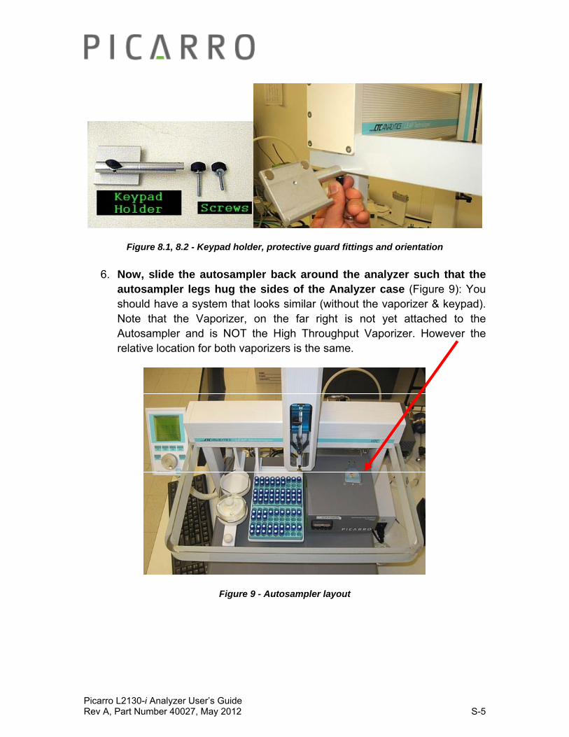
Picarro L2130-i Analyzer User’s Guide Rev A, Part Number 40027, May 2012 S-5
Figure 8.1, 8.2 - Keypad holder, protective guard fittings and orientation
6. Now, slide the autosampler back around the analyzer such that the autosampler legs hug the sides of the Analyzer case (Figure 9): You should have a system that looks similar (without the vaporizer & keypad). Note that the Vaporizer, on the far right is not yet attached to the Autosampler and is NOT the High Throughput Vaporizer. However the relative location for both vaporizers is the same.
Figure 9 - Autosampler layout
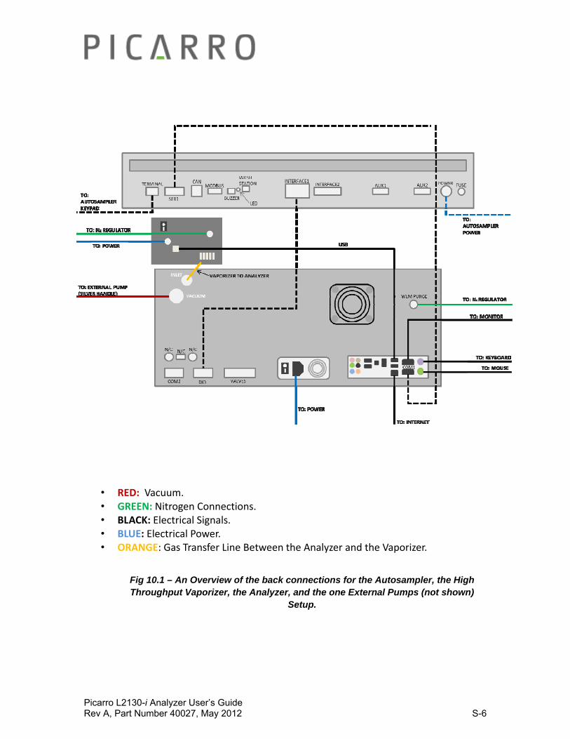
Picarro L2130-i Analyzer User’s Guide Rev A, Part Number 40027, May 2012 S-6
• RED: Vacuum. • GREEN: Nitrogen Connections. • BLACK: Electrical Signals. • BLUE: Electrical Power. • ORANGE: Gas Transfer Line Between the Analyzer and the Vaporizer.
Fig 10.1 – An Overview of the back connections for the Autosampler, the High Throughput Vaporizer, the Analyzer, and the one External Pumps (not shown)
Setup.
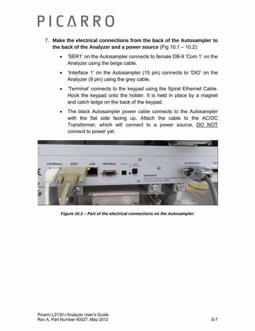
Picarro L2130-i Analyzer User’s Guide Rev A, Part Number 40027, May 2012 S-7
7. Make the electrical connections from the back of the Autosampler to the back of the Analyzer and a power source (Fig 10.1 – 10.2):
‘SER1’ on the Autosampler connects to female DB-9 ‘Com 1’ on the Analyzer using the beige cable.
‘Interface 1’ on the Autosampler (15 pin) connects to ‘DIO’ on the Analyzer (9 pin) using the grey cable.
‘Terminal’ connects to the keypad using the Spiral Ethernet Cable. Hook the keypad onto the holder. It is held in place by a magnet and catch ledge on the back of the keypad.
The black Autosampler power cable connects to the Autosampler with the flat side facing up. Attach the cable to the AC/DC Transformer, which will connect to a power source. DO NOT connect to power yet.
Figure 10.2 – Part of the electrical connections on the Autosampler.

Picarro L2130-i Analyzer User’s Guide Rev A, Part Number 40027, May 2012 S-8
8. Mount the vaporizer to the X Axis Stage (Figure 11): Check that it is the required 3” (76mm) distance from the outer edge of the right hand leg (from the front). Slide the vaporizer onto the vaporizer holder and tighten the screws.
Figure 11 - The correct positioning for the vaporizer holder relative to the Autosampler.
9. Connect N2 gas line to the Vaporizer (Figure 12). Connect the output from a nitrogen gas cylinder (supplied at a pressure of 3 ± 0.5 psig (0.2 ± 0.03 bar) to the 1/8” Swagelock connection at the rear of the vaporizer.
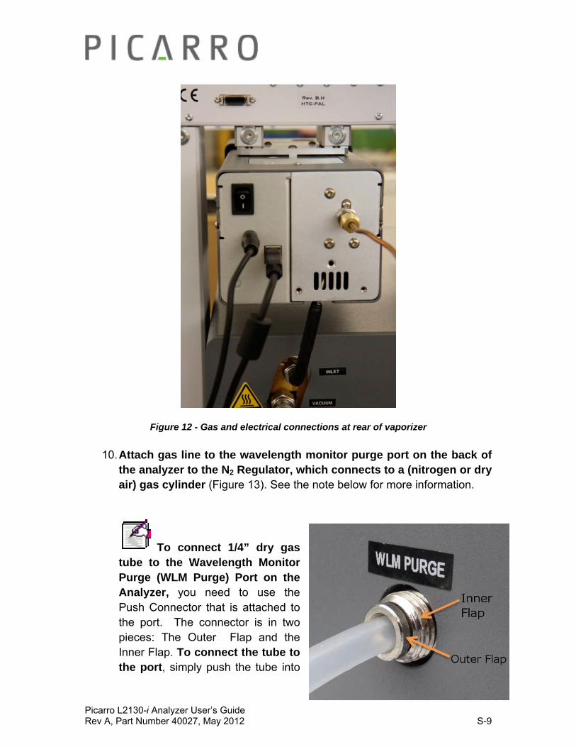
Picarro L2130-i Analyzer User’s Guide Rev A, Part Number 40027, May 2012 S-9
Figure 12 - Gas and electrical connections at rear of vaporizer
10. Attach gas line to the wavelength monitor purge port on the back of the analyzer to the N2 Regulator, which connects to a (nitrogen or dry air) gas cylinder (Figure 13). See the note below for more information.
To connect 1/4” dry gas tube to the Wavelength Monitor Purge (WLM Purge) Port on the Analyzer, you need to use the Push Connector that is attached to the port. The connector is in two pieces: The Outer Flap and the Inner Flap. To connect the tube to the port, simply push the tube into

Picarro L2130-i Analyzer User’s Guide Rev A, Part Number 40027, May 2012 S-10
the connector and then pull the tube back. If there is a space between the inner flap and the outer flap, this means that the tube is locked to the port. Do not twist and turn. To take the tube out of the port, push the Outer Flap in against the Inner Flap, and while doing this, pull out the tube. This will cause the gripping mechanism to release from the tube.
Figure 13 – Above is an N2 Regulator: Semitransparent tube on the left is from the ‘WLM Purge” Port on the Analyzer. Copper colored tube on the top left comes from the Vaporizer. Copper colored tube on the bottom right goes to the the (N2 or Dry
Air) Gas Cylinder.
11. Attach the power and USB connections to the vaporizer. Do not connect to power yet.
12. Connect the Vaporizer and the Analyzer(Figure 12). Slide the tubing connection over the tubing on the bottom of the vaporizer. Attach the ¼” Swagelock connection of the insulated tubing onto the inlet port of the analyzer as shown.
13. Check the power connections to the machines: Make sure all power cables are attached to the power outlets on the Analyzer, Vaporizer,
Picarro L2130-i Analyzer User’s Guide Rev A, Part Number 40027, May 2012 S-11
External Vacuum Pump, and the Autosampler Power Block. However, DO NOT connect to the power supply yet.
14. Carefully slide the complete system into position: Small movement of the components relative to one another is OK, the units are well locked. However, do not overly force the system, check for obstacles if the unit does not slide easily.
15. Power up the system: Plug in all the power cables (including the one for the monitor) into an appropriate power supply. Switch ON the components in the following order:
the external vacuum pump
the autosampler power supply
the vaporizer
the monitor
the analyzer power switch to ‘ON’
NOTE: The software to operate the instrument will start automatically after the operating system has loaded.
The user interface will appear a few seconds after the instrument software starts (see the figure on the following page).
NOTE: As the instrument is starting up, it is normal for there to be a delay in reporting data. This can take several minutes depending on how long it takes for the internal temperature to reach its operating point, and it is normal during this time for some concentration readings to be negative or constant. Additionally, the data selection pull down menus will not be populated with the appropriate items until data is actually being reported in the graph. This is typically less than 30 minutes, but depending on ambient temperature, the analyzer can take up to 2 hours to stabilize.

Picarro L2130-i Analyzer User’s Guide Rev A, Part Number 40027, May 2012 S-12
Training the Vaporizer:
1. The Vaporizer needs to be setup properly in order to achieve its best performance. The training of the Vaporizer injection port should be set such that the syringe is trained to the center of the Vaporizer needle guide with an injection depth of 28 mm. See Figure 14 & 15. The injection speed should be set to 50nL/sec, and the sample size should be set to 3.3uL for water with low concentrations of dissolved solids and 3.0uL for water with higher concentrations of dissolved solids.
Figure 14. Autosampler aligned to injection port of vaporizer.
Figure 15. Autosampler aligned to injection port of vaporizer (side view).
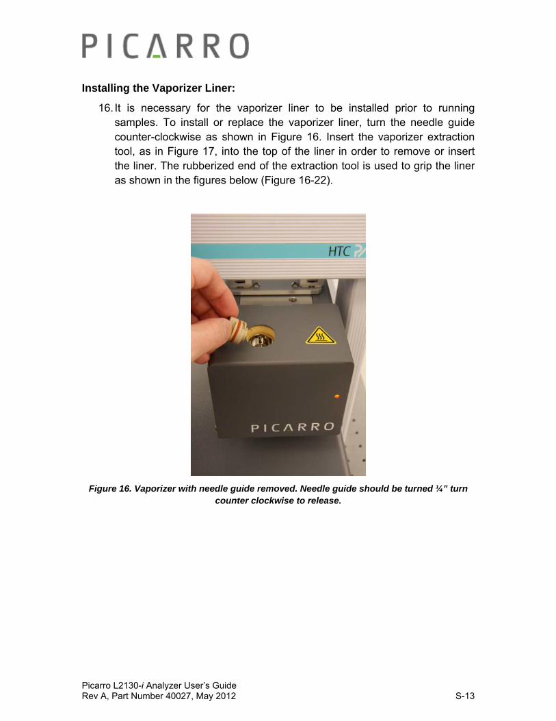
Picarro L2130-i Analyzer User’s Guide Rev A, Part Number 40027, May 2012 S-13
Installing the Vaporizer Liner:
16. It is necessary for the vaporizer liner to be installed prior to running samples. To install or replace the vaporizer liner, turn the needle guide counter-clockwise as shown in Figure 16. Insert the vaporizer extraction tool, as in Figure 17, into the top of the liner in order to remove or insert the liner. The rubberized end of the extraction tool is used to grip the liner as shown in the figures below (Figure 16-22).
Figure 16. Vaporizer with needle guide removed. Needle guide should be turned ¼” turn counter clockwise to release.

Picarro L2130-i Analyzer User’s Guide Rev A, Part Number 40027, May 2012 S-14
Figure 17. Vaporizer liner extraction tool being used to remove glass vaporizer liner.
17. The vaporizer liner should be measured as in Figure 21 below to properly adjust the autosampler syringe injection depth. It is often useful measure the depth from the top of the liner to the top of the metallic cup inside the liner. The distance should be generally ~5mm from the top to correctly correspond to an injection depth of 28mm. If it is different than 5mm, adjust the injection depth accordingly (4mm would correspond to an injection depth of 27mm, etc.).
WARNING: The vaporizer liner and the and metallic surfaces that hold the syringe guide (as seen in Figure 18 below) are extremely hot after the vaporizer power has been switched on. The surfaces will remain hot for a significant period even after the vaporizer has been switched off. Use extreme caution when extracting the vaporizer liner. To remove the liner from the extraction tool, several layers of paper towel or similar insulating material can be used to grip the liner, as shown in Figure 20 below.
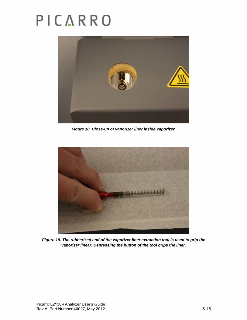
Picarro L2130-i Analyzer User’s Guide Rev A, Part Number 40027, May 2012 S-15
Figure 18. Close-up of vaporizer liner inside vaporizer.
Figure 19. The rubberized end of the vaporizer liner extraction tool is used to grip the vaporizer linear. Depressing the button of the tool grips the liner.

Picarro L2130-i Analyzer User’s Guide Rev A, Part Number 40027, May 2012 S-16
Figure 20. Using a paper towel to grip a hot vaporizer liner to remove it from the extraction tool. The liner is released from the tool by depressing the button as shown.
DO NOT TOUCH WITH BARE HANDS! YOU CAN GET BURNED.
Figure. 21. It may be necessary to measure the depth from the top of the liner to the metallic cup. It should be generally 5mm from the top to correctly correspond to an
injection depth of 28mm. If it is different than 5mm, adjust the injection depth accordingly (4mm would correspond to an injection depth of 27mm, etc.).
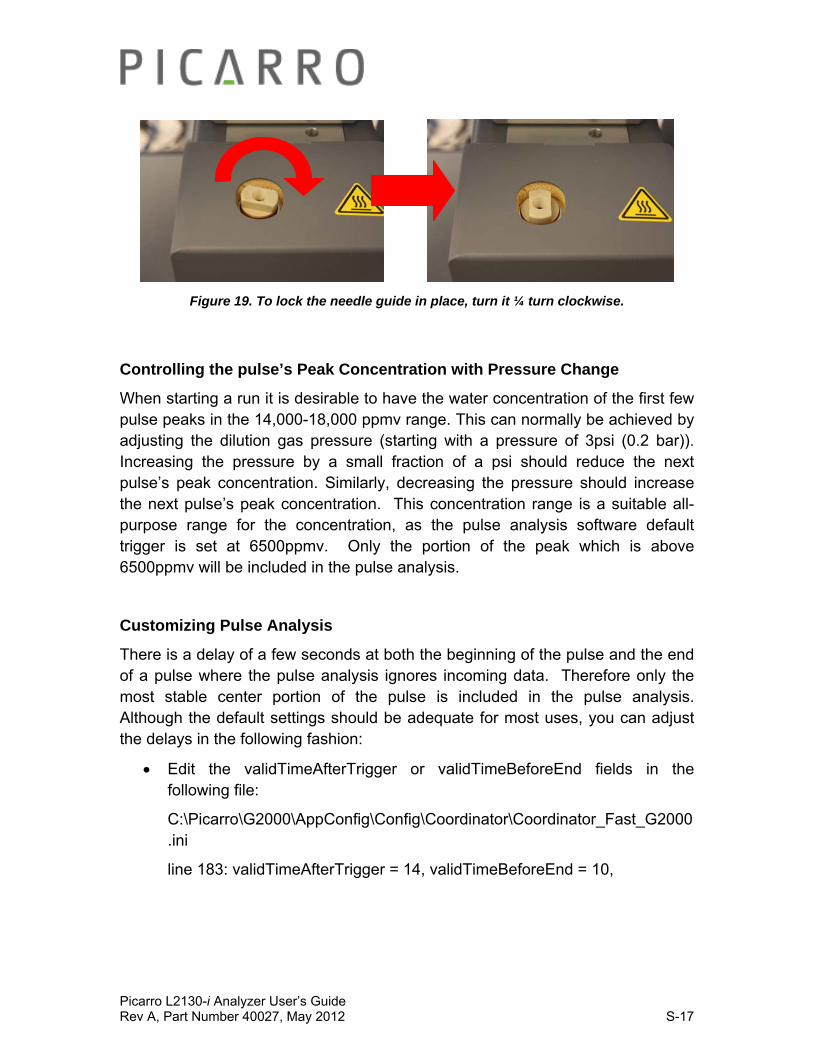
Picarro L2130-i Analyzer User’s Guide Rev A, Part Number 40027, May 2012 S-17
Figure 19. To lock the needle guide in place, turn it ¼ turn clockwise.
Controlling the pulse’s Peak Concentration with Pressure Change
When starting a run it is desirable to have the water concentration of the first few pulse peaks in the 14,000-18,000 ppmv range. This can normally be achieved by adjusting the dilution gas pressure (starting with a pressure of 3psi (0.2 bar)). Increasing the pressure by a small fraction of a psi should reduce the next pulse’s peak concentration. Similarly, decreasing the pressure should increase the next pulse’s peak concentration. This concentration range is a suitable all-purpose range for the concentration, as the pulse analysis software default trigger is set at 6500ppmv. Only the portion of the peak which is above 6500ppmv will be included in the pulse analysis.
Customizing Pulse Analysis
There is a delay of a few seconds at both the beginning of the pulse and the end of a pulse where the pulse analysis ignores incoming data. Therefore only the most stable center portion of the pulse is included in the pulse analysis. Although the default settings should be adequate for most uses, you can adjust the delays in the following fashion:
Edit the validTimeAfterTrigger or validTimeBeforeEnd fields in the following file:
C:\Picarro\G2000\AppConfig\Config\Coordinator\Coordinator_Fast_G2000.ini
line 183: validTimeAfterTrigger = 14, validTimeBeforeEnd = 10,

Picarro L2130-i Analyzer User’s Guide Rev A, Part Number 40027, May 2012 S-18
You can similarly adjust the level that triggers a pulse analysis event by changing the 6500 value in the upslope or downslope trigger in the following file:
C:\Picarro\G2000\AppConfig\Config\Coordinator\Coordinator_Fast_G2000.ini
line 178: thres1Pair = [6500, 30000] #this is the upslope trigger
line 179: thres2Pair = [6500, 30000] #this is the downslope trigger
Picarro L2130-i Analyzer User’s Guide Rev A, Part Number 40027, May 2012 S-19
Troubleshooting:
Coordinator stops with an error
This typically happens because the H2O peak concentration is so far below 12000ppmv (typically below the default value of 6500) that the pulse analysis cannot occur. Check that there is adequate sample and that the syringe is ok or see the “H2O Peak Concentration is below 12000ppmv” section below.
H2O Peak Concentration is below 12000ppmv
Verify that the autosampler handset’s injection speed into the vaporizer is set to 50nL per second and that you are using a 10uL syringe.
Decrease Dilution Gas Pressure in 10% increments between each pulse until resolved.
If the H2O Peak Concentration is still below 12000ppmv after a number of pressure adjustments, pause the job on the autosampler handset and check whether the sample source is running low on sample. The Vaporizer uses roughly 6.7uL of sample per injection. If there is adequate sample, check that the syringe depth is set to reach below the surface of the sample using the autosampler handset. If everything appears to be correct, manually remove the syringe and check that it is working properly. Note that syringes wear out more rapidly when working with samples that have a large amount of solids, i.e. seawater.
H2O Peak Concentration is above 15000ppmv
Verify that the autosampler handset’s injection speed into the vaporizer is set to 50nL per second and you are using a 10uL syringe.
Increase Dilution Gas Pressure in 10% increments between each pulse until resolved.
If the H2O Peak Concentration is still above 15000ppmv after a number of pressure adjustments, pause the job on the autosampler handset and check whether the glass vaporizer liner is obstructed. The liner is a consumable item upon which solid residue from the sample is deposited during sample vaporization. Over time the liner can become obstructed

Picarro L2130-i Analyzer User’s Guide Rev A, Part Number 40027, May 2012 S-20
and will need to be replaced. This failure mode is more pronounced in samples with a large amount of solids, i.e. seawater.
H2O Peak Concentration is noisy on most injections
Some noise in peak concentration is to be expected. If the concentration noise is pronounced, it may be indicative of the vaporizer injection depth not be set deeply enough to allow the syringe to make contact with the heated metal reservoir in the injection liner. Try adding 3mm to the injection depth in the handset; this step can be repeated a couple of times.
Syringe breaking or wearing out in a short period
The 10uL syringes are robust when running with water that has few dissolved solids. The autosampler handset does, however, need to be set properly for the syringes not to be damaged. Among the most important settings are the various speeds at which the syringes are filled or injected. It is recommended not to fill or inject the syringes at a speed in excess of 1uL/second for pure water, or greater than 0.5uL/second for water with significant dissolved solids. Please check the autosampler handset settings to verify that these settings are not exceeded. Another important setting is the sample size; syringes should not be filled to more that 3.33uL if injecting pure water, or 3.00uL if using water with significant dissolved solids. (Note the actual volumes are doubled because the autosampler generally is set by default to assume the syringes are 5uL rather than 10uL). When running syringes with significant amounts of dissolved solids the syringe’s lifespan will be reduced.
Concentration Spikes at the end of the pulse
This is usually indicative of the sample not being fully vaporized before the syringe is removed from the injection port. Try increasing the post injection delay; in many cases a value of 18 seconds is optimal.
Pulse time is longer than two minutes
If the setup seems to be otherwise working appropriately then there is nothing specifically wrong if the pulse time is longer than two minutes. Since longer pulses are composed of more measurement points, the pulse
Picarro L2130-i Analyzer User’s Guide Rev A, Part Number 40027, May 2012 S-21
integration results might even be slightly improved. However, if you wish to improve throughput you can increase the dilution gas pressure in not more than 10% increments until pulse peak concentrations are closer to 12500ppmv. This should dry out the pulse faster. You can also try reducing the post injection delay; this risks causing concentration spikes at the end of the pulse, so be careful doing this. In any case, values under about 12 seconds are not recommended. It may also be advisable to try reducing the sample volume. Pulse lengths are typically linearly related to sample volume. Sample volumes in the 2.9uL to 3.33uL range are typical.
Caution: do not use sample volumes above 3.33uL (for pure water), or 3.0uL (for liquids with significant dissolved solids), as this reduces the syringe life.
Poor pulse integration is occurring because noisy measurements at the beginning or end of the pulse are being included in the integration as shown by the red dots for the isotope measurements
In this case, try customizing the pulse analysis as in the section above. Typically, increasing the delay for validTimeAfterTrigger or validTimeBeforeEnd by 2-3 seconds and re-running the coordinator to see if the noisy points have been excluded would be the first thing to try.
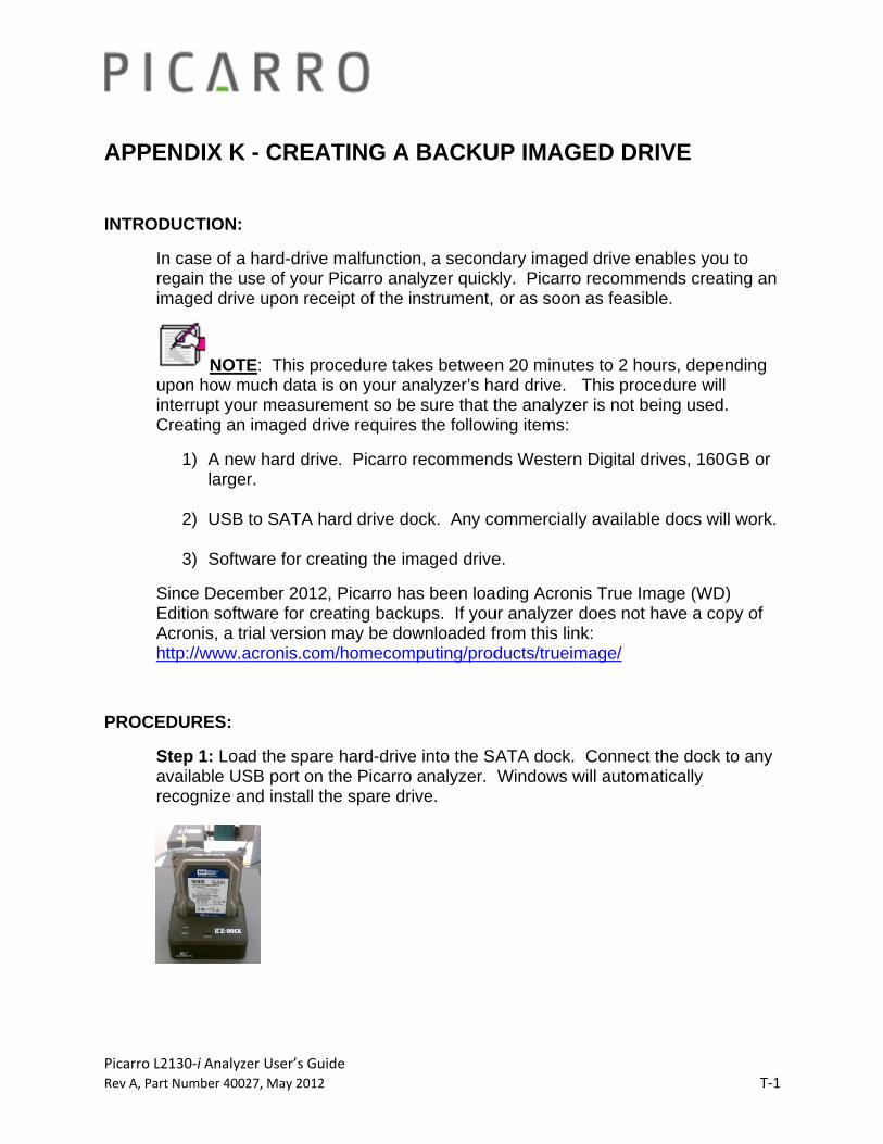
Picarro L2Rev A, Part
APPE
INTROD
Inreim
uinC
SEAh
PROCE
Sare
2130‐i Analyzet Number 4002
ENDIX K
DUCTION:
n case of a egain the umaged drive
NOTEpon how m
nterrupt youCreating an
1) A newlarger
2) USB
3) Softw
Since DecemEdition softwAcronis, a tr
ttp://www.a
DURES:
Step 1: Loavailable USecognize an
er User’s Guid27, May 2012
- CREA
hard-drive se of your Pe upon rece
E: This promuch data isur measureimaged dri
w hard driver.
to SATA ha
ware for cre
mber 2012,ware for crerial version acronis.com
d the spareSB port on tnd install th
de
ATING A
malfunctioPicarro anaeipt of the i
ocedure taks on your anment so beve requires
e. Picarro
ard drive do
ating the im
, Picarro haeating backmay be dow
m/homecom
e hard-drivethe Picarro he spare dri
BACKU
n, a secondalyzer quicknstrument,
kes betweennalyzer’s ha
e sure that ts the follow
recommend
ock. Any co
maged drive
as been loaups. If youwnloaded f
mputing/prod
e into the SAanalyzer.
ive.
UP IMAG
dary imagekly. Picarroor as soon
n 20 minuteard drive. the analyzeing items:
ds Western
ommerciall
e.
ding Acronur analyzer from this linducts/trueim
ATA dock. Windows w
GED DRIV
d drive enao recommenn as feasible
es to 2 houThis proce
er is not bei
n Digital driv
y available
nis True Imadoes not ha
nk: mage/
Connect thwill automat
VE
ables you tonds creatine.
rs, dependedure will ing used.
ves, 160GB
docs will w
age (WD) ave a copy
he dock to tically
T‐1
o g an
ing
B or
work.
of
any

Picarro L2Rev A, Part
S
2130‐i Analyzet Number 4002
Step 2: “Qu
er User’s Guid27, May 2012
uick format”
de
” the new d
rive, choos
se NTFS filee system (d
default)
T‐2
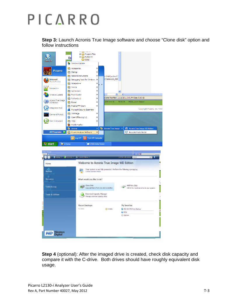
Picarro L2Rev A, Part
Sfo
Scu
2130‐i Analyzet Number 4002
Step 3: Lauollow instru
Step 4 (optioompare it wsage.
er User’s Guid27, May 2012
nch Acronisctions
onal): Afterwith the C-d
de
s True Imag
r the imageddrive. Both
ge software
d drive is cdrives sho
e and choo
reated, cheould have ro
se “Clone d
eck disk capoughly equi
disk” option
pacity and valent disk
T‐3
n and
k