l p al 3/a/n
TRANSCRIPT

E
, . -,
hM%j=
Q' t'- UNITED STATES~
.j j NUCLEAR REGULATORY COMMISSION* REGION 11o
' j[ 101 MARIETTA ST., N.W.
e,,,, ATLANTA, GEORGIA 30323
Report No.: 50 ''.6/89-04
Licensee: _ System Energy Resources, Inc.Jackson, MS 39205
Docket No.: 50-416 License No.: NPF-29
Facility Name: Grand Gulf Nuclear Station )
' Inspection Conducted: January 14 - February 17, 1989
_3 !/ 6 f(YInspect rs: / eH. 0. Ch'ristensen, Senior Resident Inspector Date Signed%
L P AL 3/a/nJ. L. Math'e, Resident Inspector Date Signed_
Approved by: 244-- '. 3 [4 /85/-F. S. /Cantrell Section Chief, Date Signed
Division of Reactor Projects
SUMMARY
Scope: The resident inspectors conducted a routine inspection in the followingareas: Operational safety verification; maintenance observation; surveillanceobservation; surveillance procedures and records; engineering safety features(ESF) system walkdown; preparation for refueling; action on previous inspectionfindings; document control program; and evaluation of licensee self-assessmentcapability. The inspectors conducted backshift inspections on January 12, 26and February 2, 12, 1989.
Results: Within the areas inspected, one violation and one unresolved item was'
identified: Failure to perform a safety evaluation for the storage of EC0DEXresin inside containment, paragraph 9. The walkdown of the RCIC systemindicated a number of labelling errors, particularly in the electrical panelarea, paragraph 7. The surveillance procedures and records program appearsadequate with no major deficiencies.
8904030228 890316 ,
ADOCK 0 % 4d6PDRG

__ __ _ _ --. _ - . _ _ _ _ - _
l, .
|-
.
1*
.
,
-
|
|REPORT DETAILS
| 1. Persons Contacted
Licensee Employees'
*M. Bakarick, Superintendent, System SupportJ. G. Cesare, Director, Nuclear Licensing i
W. T. Cottle, Vice President of Nuclear Operations*D. G. Cupstid, Superintendent, Technical SupportL. F. Daughtery, Compliance Supervisor
*J. P. Dimmette, Manager, Plant MaintenanceS. M. Feith, Director, Quality Programs
*C, R. Hutchinson, General Manager GGNSR. H. McAnulty, Electrical Superintendent
*R. V. Moomaw, Technical Assistance, Plant Maintenace ManagerA. S. McCurdy, Technical Asst., Plant Operations Manager .
L. B. Moulder, Operations SuperintendentJ. H. Mueller, Mechanical Superintendent
*J. C. Roberts, Manager, Performance and System EngineeringJ. V. Parrish, Chemistry / Radiation Control Superintendent
*J. L. Robertson, Superintendent, Plant LicensingR. F. Rogers, Manager, Special ProjectsS. F. Tanner, Manager, Quality ServicesL. G. Temple, I & C SuperintendentF. W. Titus, Director, Nuclear Plant EngineeringM. J. Wright, Manager, Plant Support
*J. W. Yelverton, Manager, Plant Operations
Other licensee employees contacted included technicians, operators,security force members, and office personnel.
* Attended exit interview
2. Plant Status
Unit 1 began and ended the inspection period operating at approximately100% power. The licensee had several surveillance electronic timeresponse test failures and functional test failures. However, correctionswere made without interruption of plant's operation. The next refuelingoutage is scheduled for March 17, 1989.
3. Operational Safety Verification (71707)
The inspectors were cognizant of the overall plant status, and of anysignificant safety matters related to plant operations. Daily discussionswere held with plant management and various members of the plant operatingstaff. The inspectors made frequent visits to the control room.Observations included the verification of instrument readings, setpointsand recordings, status of operating systems, tags and clearances on
. _ _ _ - _ - _ _ _ _ _ _ _ _ _ _ _ _ - _ - _ _ _ -

- - _ _ _ _ _ _ _ - - _ - _ _ - _ _ _ _ - _ _ - _ _ _ .
.-
'
.
2.
equipment controls and switches, annunciator alarms, adherence to limiting .
'
conditions for operation, temporary alterations in effect, daily journalsand data sheet entries, control room manning, and access controls. Thisinspection activity included numerous informal discussions with operatorsand their supervisors.
On a weekly basis selected engineered safety feature (ESF) systems wereconfirmed operable. The confirmation was made by verifying that accessiblevalve flow path alignment was correct; power supply breaker, and fusestatus was correct; and instrumentation was operational. The followingsystems were verified operable: Containment spray, and standby gastreatment system (Train B). Additionally, the inspectors conducted amodified system walkdown on the low pressure core spray system, highpressure core spray system, emergency electric power system, suppressionpool makeup system, and the automatic depressurization system. Thewalkdowns used the Grand Gulf Probabilistic Risk Assessment Based SystemInspection Plan as a guide.
General plant tours were conducted on a weekly basis. Portions of thecontrol building, turbine building, auxiliary building and outside areaswere visited. The observations included safety related tagoutverifications, shift turnovers, sampling programs, housekeeping andgeneral plant conditions, the status of fire protection equipment, control
iof activities in progress, problem identification systems, and containmentisolation. Additionally, the licensee's onsite emergency responsefacilities were toured to determine facility readiness.
The inspectors observed health physics management involvement andawareness of significant plant activities, and observed plant radiationcontrols. The inspectors verified licensee compliance with physicalsecurity manning and access control requirements. Periodically the
inspectors verified the adequacy of physical security detection andassessment aids.
During the week of January 31, 1989, a Regional security inspectorreviewed (see Inspection report 416/89-03) the licensee's progress ofenclosing Unit 2 within the protected area. A number of items required
i completion before activating the new boundary area. The residentinspectors verified that these items were completed before the newprotected area boundary was activated on February 9, 1989.
On February 10, 1989, the licensee identified that a SERI employeeunintentionally took a handgun into the protected area. Upgraded X-raymachines have been put in service since this incident occurred. Thisincident was called in to NRC in a one-hour report and documented inIncident Report 89-2-3. Further investigation by the licensee is on-goingand will be followed by Regional based security inspectors. |
The inspectors reviewed safety related tagout 18443, to prevent operationof RHR valve E12-F052 A and B. The review ensured that the tagout was
i
_ _ _ _ _ _ _ _ _ _ _ _ _ _ _ _ _ _ _ _ _ _
_ _ - _ _ _ _ _ _ - _ _ _ _ _ _ _ - _ _ _ _ _ _ _ __ __
'
*
.
'
3>
properly prepared and performed, and the tagged components were in therequired position.
The inspectors verified that the following containment isolation valveswere in there correct lineup; E61-F002A (combustible gas control) andC41-F006 (standby liquid control).
No violations or deviations were identified.
4. MaintenanceObservation(62703)
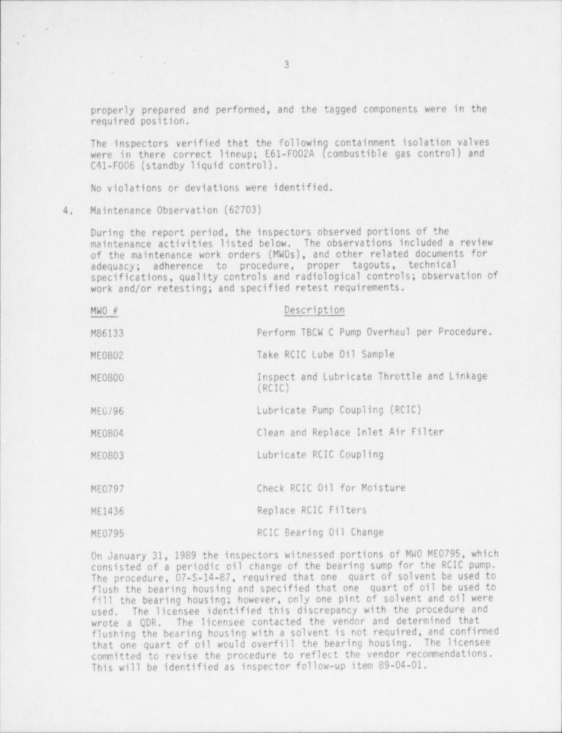
During the report period, the inspectors observed portions of themaintenance activities listed below. The observations included a reviewof the maintenance work orders (MW0s), and other related documents foradequacy; adherence to procedure, proper tagouts, technicalspecifications, quality controls and radiological controls; observation ofwork and/or retesting; and specified retest requirements.
MWO # Description
M86133 Perform TBCW C Pump Overhaul per Procedure.i
ME0802 Take RCIC Lube Oil Sample
iME0800 Inspect and Lubricate Throttle and Linkage
(RCIC)
ME0796 Lubricate Pump Coupling (RCIC) !
ME0804 Clean and Replace Inlet Air Filter~\
ME0803 Lubricate RCIC Coupling
!
ME0797 Check RCIC Oil for Moisture
ME1436 Replace RCIC Filters
ME0795 RCIC Bearing Oil Change
On January 31, 1989 the inspectors witnessed portions of MW0 ME0795, whichj consisted of a periodic oil change of the bearing sump for the RCIC pump.
The procedure, 07-S-14-87, required that one quart of solvent be used toflush the bearing housing and specified that one quart of oil be used tofill the bearing housing; however, only one pint of solvent and oil wereused. The licensee identified this discrepancy with the procedure andwrote a QDR. The licensee contacted the vendor and determined thatflushing the bearing housing with a solvent is not required, and confirmedthat one quart of oil would overfill the bearing housing. The licenseecommitted to revise the procedure to reflect the vendor recommendations.This will be identified as inspector follow-up item 89-04-01.
- - - - - _ _ _ _ _ - _ _ - _ _ _ . - - _ _ _ _ _ _ - _ _ _ _ _ _ _ _ _ _ _ _ _ _ _ _ _ - _
. . _ _ _ _ . _ . _
*
.
*
.
4.
.
No violations or deviations were identified.
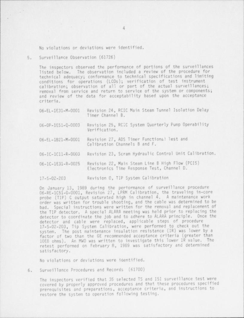
5. Surveillance Observation (61726)
The inspectors observed the performance of portions of the surveillancelisted below. The observation included a review of the procedure fortechnical adequacy; conformance to technical specifications and limitingconditions for operations (LCOs); verification of test instrumentcalibration; observation of all or part of the actual surveillance;removal from service and return to service of the system or components;and review of the data for acceptability based upon the acceptancecriteria.
06-EL-1E31-M-0001 Revision 24, RCIC Main Steam Tunnel Isolation DelayTimer Channel B.
06-0P-1E51-Q-0003 Revision 25, RCIC System Quarterly Pump OperabilityVerification.
06-EL-1821-M-0001 Revision 27, ADS Timer Functional lest andCalibration Channels B and F.
06-IC-1C11-R-0003 Revision 23, Scram Hydraulic Control Unit Calibration.
06-10-1E31-R-0025 Revision 22, Main Steam Line B High Flow (PCIS)Electronics Time Response Test, Channel D.
17-S-02-203 Revision 0, TIP System Calibration
On January 13, 1989 during the performance of surveillance procedure06-RE-1C51-0-0001, Revision 27, LPRM Calibration, the traveling in-coreprobe (TIP) C output saturated high in channel 4. A maintenance workorder was written for trouble shooting, and the cable was determined to bebad. Special instructions were written for the removal and replacement ofthe TIP detector. A special ALARA meeting was held prior to replacing thedetector to coordinate the job and to adhere to ALARA principle. Once thedetector and cable were replaced, applicable steps of procedure17-S-02-203, Tip System Calibration, were performed to check out thesystem. The post maintenance insulation resistance (IR) was lower by afactor of two than the GE recommended acceptance criteria (greater than10E8 ohms). An MWO was written to investigate this lower IR value. Theretest performed on February 8, 1989 was satisfactory and determinedsatisfactory.
No violations or deviations were identified.
6. Surveillance Procedures and Records (61700)
The inspectors verified that 35 selected TS and ISI surveillance test werecovered by properly approved procedures and that these procedures specifiedprerequisites and preparations, acceptance criteria, and instructions torestore the system to operation following testing.
._- __--_-- _ - .__

_ _ _ _ _ _ _ - _ - - _ _ _ _
*.
.
.
5
Technical Specification 4.6.4.2 requires that each automatic isolationvalve shown in Table 3.6.4-1 shall be demonstrated operable during coldshutdown refueling at least once per 18 months by verifying that on anisolation test signal each automatic isolation valve moves to itsisolation position. Technical Support Procedure 09-S-05-7, Revision 16,GGNS Technical Specification / Surveillance Program Master Cross-Index, listall procedures that meet each required TS. A review of the fiveprocedures; 06-0P-1B21-R-0006, 06-0P-1P75-R-0003, 06-0P-1P75-R-0004,06-0P-1P81-R-0001, and 06-0P-1821-V-0001; that addressed TS 4.6.4.2,indicated that two valves, E12-F028A and B, RHR heat exchanger tocontainment spray sparger inlet valves, were not included in the fivereferenced procedure. The licensee determined that the requirements forTS 4.6.4.2 was met by Surveillance Procedure 06-0P-1E12-R-0022, RHRContainment Spray Initiation Logic System Functional Test. The licenseeagreed to issue a procedure change to include the surveillance in the" master cross-index" and to reflect the TS requirement in06-0P-1E12-R-0022.
The inspectors questioned whether the intent of TS 4.6.4.2 was being metfor the main steam line isolation valves. Surveillance procedure06-0P-1821-V-0001, MSIV Operability Test, strokes the valves closed byusing each valve individual manual handswitch while the plant is inoperational condition 2 above 600 psig. The licensee stated that theybelieved the intent of the surveillance requirement was being met by theabove procedure. In discussion with NRR representatives, use of themanual handswitch was determine acceptable because the manual switchoperates the same relays that the isolation signal operates. No otherdeficiencies were identified.
Twenty-one completed surveillance tests were reviewed to determine thatthe tests were in conformance with TS, ISI program, and proceduralrequirements; tests had been reviewed as required by administrativeprocedure 01-5-06-12, Revision 15, Grand Gulf Nuclear Station SurveillanceProgram; tests had been performed within the time frequencies specified bythe TS or ISI program; appropriate action had been taken for any itemfailing acceptance criteria; and test were performed by qualifiedindividuals.
A review of the Battery 1A3 Performance Discharge Test, 06-EL-1L21-0-0001,conducted during the second refueling outage indicated that thesurveillance was performed correctly, but the data sheet had been filledout incorrectly. The electrical superintendent stated that training willbe conducted in the proper way to conduct and document the battery .
|performance discharge test.
Overall, the surveillance program appear adequate and meets therequirement of TS.!
1
- _ _________ _-______-___-___ - _ _ _ _ -

_______ - _ ,
.
.'J
6'
.
No violations or deviations were identified.
7. Engineered Safety Features System Walkdown (71710)
The inspectors conducted a complete walkdown on the accessible portions ofthe reactor core isolation cooling (RCIC) system to verify the following:Confirm that the system lineup procedure matches the plant drawing and theas-built configuration; identify equipment condition and items that mightdegrade plant performance; verify that valves in the flow path are incorrect positions as required by procedure and that local and remoteposition indications are functional; verify the proper breaker position atlocal electrical boards and indications on control boards; verify that
instrument calibration dates are current.
The residents walked down the system using system operating instruction04-1-01-E51-1, Revision 30, Reactor Core Isolation Cooling and Piping, andinstrument diagram (P&ID) M-1083A, Revision 24 and M-1083B, Revision 26.
The operating instruction electrical lineup checksheet, Attachment III,component description differed from the actual equipment label as follows:
Breaker No. Component Description Breaker Label
52-153129 RCIC STM SPLY ORWL OTBD ISOL STM SPLY OTBD ISOL
52-1P53108 MOTOR AND COMPRESSOR HEATERS SPARE
52-1P53118 VALVE MOTOR HEATER MOV HTR VERTICALSEC I
52-1P53116 VALVE MOTOR HEATER M0V HTR VERTICALSEC J
52-1P53112 VALVE MOTOR HEATER MOV AND STARTERSPACE HTR
t
52-1P51104 VALVE MOTOR HEATER MOV AND STARTERSPACE HTR
( 52-1P56120 DIV 1 RCIC CONTROL POWER CR PGCC PANEL1H13-P632 LK DETSYS
52-1P56112 DIV 1 TRIP UNIT ISOLATOR CR PGCC PANEL
POWER SUPPLY 1H13-P629 LPCS
52-1P56117 RCIC 1 TEST CKTS AND CR PGCC PANEL
STATUS LIGHTS 1H13-P601 RCICF066 LIMIT SWITCH 1
t _ __ _ _ _ _ _ _ _ - _ _ _ _ _ _ _ _ _ _ _ _ _ _ _ _ _ -

__ _ _ _ . __ _ __ . _ _ _ _ _ _ -__
*.
.'*
7,
,.
52-IP66108 DIV 2 TRIP UNIT ISOLATOR CR PGCC PANELISOLATOR POWER SUPPLY IH13-P618 RHR
52-1P66112 DIV 2 TEST CKTS CR PGCC PANELAND STATUS LIGHTS 1H13-P601 RCIC
52-IP66111 DIV 2 RCIC CONTPOL POWER CR PGCC 1H13-P642LK DET SYS
72-11B13 AIR TO A-F004 TURB EXHAUST DRAIN 72-11813E51AIR TO A0-F025 TURB STEM LINE PGCC 1H13-P600DRAIN A0-F004 LIMIT SWITCHA0-F025 LIMIT SWITCH
72-11BSo DIV 2 TRIP UNIT ISOLATCR POWER 72-11835E21PGCC 1H13-P618
72-11B39 DIV 2 RCIC RELAY LOG PGCC IH13-P618
72-11B14 DIV.2 TRIP UNIT 72-11B14312ISOLATOR POWER PGCC PNI 1H13-P618
72-11A39 TURB GOV VALVE LIMIT SWITCH 72-11A39E51TURB TRIP AND THROTTLE LIMIT PGCC PNL 1H13-P601SWITCH A0-F026 LIMIT SWITCHA0-F005 LIMIT SWITCHA0-F0054 LIMIT SWITCHAIP 10 A0-F026 STM LINE DRAINAIR TO A0-F006 TURB EXHAUST DRAIN
72-11A24 RCIC TURB SPEED CONTROL POWER 71-11A24E51DIV 1 RELAY LOGIC POWER SUPPLY PGCC PNL 1H13-P621RCIC TURB REMOTE TRIP POWER SUPPLY
72-11A32 RCIC TURB FLOW CONTROLLER POWER PGCC PNL 1H13-P632
72-11A18 DIV 1 TRIP UNIT ISOLA 5OR POWER 72-11A18E21SUPPLY PGCC PNL 1H13-P629
72-11A3B DIV 1 TRIP UNIT ISOLATOR POWER 72-11A38E12SUPPLY PGCC 1H13-P629
72-11A16 RCIC STM SPLY TO PCIC TURB 72-11A16E51RCIC VALVE F045
72-11A21 RCIC TURB TRIP AND THROT-VLV RCIC TURB TRIP,
________ _ ___ _ _ _ _ _

. _ . _ _ - _. _ _ _ -_ _ _ _ _ _ _ _ _ _ _ _ _ _ _ _ _ _ _ - _ _ _ _ _ - _ _ _
*.
*
.
-,
-
1i 8
52-1P31210 120 Vac INST BUS CR PGCC PNL1H13-P632LK DCT SYS
52-1P11305 LEAK DETECTION S0Vs 1H22-P176POWER SUPPLY
08-1Y71-12 RCIC TEST RTN FCV TO CST B0P PROCESSINSTRUMENT CAB1H13-P843N5
52-1P56115 120 Vac FEEDER TO K500 AND K501A LOCAL CONTROL
POWER SUPPLIES PANEL REMOTE SDSYSTEM
The RCIC annunciator panels were reviewed using the System OperatingInstruction, Attachment IV, System Alarm Index. The following differenceswere noted:
Alarm Name Panel Grid Actual Grid
Rr.C DIV 1 1H13-0601-21A A2 AlSTM SPLY PRESS L0
RCIC VAC BRKR 1H13-P601-21A E3 04
ISOL VLV F078NOT FULLY OPEN
The following Alarm was not on the alarm index:
Alarm Name Panel Grid
RCIC GL SEAL 1H13-P601-21A ElAIR PRESS HI
The folic'.-ing Alarm label differed from tLe SOI.
Panel Name In 501 Actual Namei
1H13-P601-21A-E4 RCIC TURB OIL PRESS L0 RCIC TURBBEARING OIL PRESSL0
The inspectors were informed that the licensee is implementing a newlabelling program, procedures are being developed, and that they arewalking down the safety related systems to determine labellingdeficiencies. The licensee stated that full implementation of thisprogram will take several years, including the B0P portion of the plant.The inspector stated that this was not an acceptable schedule forsafety-related systems. This is identified as an inspector follow-up item(416/89-04-02).
. ._. __ . _ _ __-_________ _ _ A

- _ - _ _ _ _ - . _ .__
.-*
.
.
9-
.
The following deficiencies were identified during the system walkdown:
-Instrument taps, PP-N400, N401, N402, N403 are missing caps.-Valve F022, RCIC inboard test return to CST, local indicator indicated10 percent open, a normally closed valve.
-Valve F045, RCIC steam supply to RCIC turbine local indicator 1-dicated30% open, a normally closed valve.
-Valve F046, RCIC water to turbine lube oil cooler, actuator has a smalloil leak.
-RCIC governor valve has water leaking from the valve spring area.-The lube oil cooler area is dirty.
-The area under the minimum flow line next to the RCIC room wall isdirty.
-Valves F251 and F252, minimum flow line to suppression pool drainvalves, are locked closed valves, the 50I has them as closed valves.
The correction of the above deficiencies will be an inspector followupitem. (416/89-04-03).
The inspectors reviewed M0 VATS test data and limit switch setting for fiveRCIC valves. The review ensured that the M0V limit switch settings wereset to the requirements of IE Bulletin 85-03, Motor Operated Valve CommonMode Failures During Plant Transients Due to Improper Switch Settings.During the MOVATS testing of E51-F045, RCIC steam supply to RCIC turbinevalve, the as-found closing torque switch trip thrust was 98,675lbs-force. The licensee adjusted the torque switch setting to reduce thetorque below the valve's limiting thrust of 58,000 lbs-force and wrote amaterial non-conformance report (0520-87). The MNCR required the keybrushing set screws to be replaced and to inspect the yoke arms forcracking. The actions of the MNCR were completed under MWO-M77365.
The inspectors reviewed GE Service Information Letters (SIL), IE Noticesand Bulletins applicability to the RCIC system. The following werereviewed:
IEN 82-16 HPCI/RCIC High Steam Flow.IEN 82-26 RCIC and HPCI Turbine Exhaust Check Valve Failure.IEN 88-69 AFW (RCIC) Turbine Overspeed Trip (Polyurethane
Tappet).IEN 88-08 Reduced Reliability of Steam-Driven Auxiliary
Feedwater Pumps Caused by Instability of WoodwardPG-PL Type Governors.
GE SIL #336 Surveillance Testing Recommendations for HPCI andRCIC Systems.
GE SIL #393 RCIC Turbiae Journal Bearing Locating Pin.GE SIL #351 HPCI and RCIC Turbine Control System Calibration.GE SIL #319 HPCI and RCIC Turbines Drive Gear Assembly.
The licensee has reviewed the above IENs and SIls for applicability to theRCIC System. GE SIL 319 recommended that the drive gear assemblies(gears, shaft bushing and thrust washer) on the RCIC turbines be inspected
_ - ___- _ _ _ _ - - _ _ _ _ _ _ _ _ _ _ _ _ _ _ _ _ _ - _ _ _ _ _ _ _ _ _ _ _ _ _ _ _

__
*.
.
.
~
.
10 j'
i
f
|for evidence of wear and overheating. MWO M64978 was initiated to perform )
'
the inspection per procedure 07-S-14-301. The work was completedsatisfactory on September 8, 1986. Additionally, GE recommended thisinspection be performed every 6 months or after 25 hours accumulated runtime which ever comes first. SERI records show that this inspection hasbeen performed only once since the SIL came out. Telephone conversationwith GE by SERI System Engineer revealed that a revision to SIL 319 isbeing issued soon to recommend a 18-month inspection of the turbine drivegear assembly. The licensee has initiated a preventive maintenance taskcard for inspecting the turbine drive gear assembly every 18 months perprocedure 07-S-14-301. This item will be tracked as inspector followupitem 89-04-03.
The RCIC system appears to be in good condition and the plant has takenappropriate actions to maintain the system in a ready state.
No violations or deviations were identified.
8. Preparation for Refueling (60705)
On January 20, 1989, Grand Gulf received a load of new fuel for the thirdrefueling outage. The first shipment of Advance Nuclear Fuel was incrates containing two fuel bundle per crate. Fuel receipt was performedin accordance with procedure 17-S-02-110, Revision 0, New Fuel Processing.The inspectors reviewed the shipping documentation and inspected tneshipment to ensure that it complied with the shipping papers (PackingList Bill of Lading, etc.). The fuel crate accelerometers were verifiedto be untripped prior to inspecting the fuel assembly by licensee. Thefuel assemblies were inspected in accordance with procedure 17-S-02-110.After inspection, the fuel was channeled prior to storage in the spentfuel pool.
No violation or deviations were identified.
9. Action on Previous Inspection Findings (92701,92702)
(0 pen) Inspector Followup Item 416/86-36-01, Establish criteria fordetermining when to clean ESF switchgear room coolers piping. Criteriawere placed in procedures 04-1-03-T46-1 and 04-1-03-T46-2 for the A and BESF Switchgear Room Coolers Flow Test respectively. If any flows are lessthan the criteria listed, the cooler is to be declared inoperable and TSPS101 followed. The criteria for cleaning the room cooler was satisfactory.However, steps 7.4.1.C of the revised procedures instructed the operatorto follow TSPS 101 for any coolers found inoperable. NRC letter datedJanuary 25, 1989 to SERI discussed a problem area of GGNS TechnicalSpecification 3/4.8.3. The ESF room coolers specified in positionstatement 101 serves the Divisional I and II electrical switchgear andelectrical penetration rooms. When the ESF room coolers are declaredinoperable, the MCC and LCC would be declared inoperable, and the actionstatements associated with this equipment must be followed. The actionstatements for TS 3/4.8.3 specifies an allowable outage time of 8 hours
__ _ ___-- ________-_-_ _ __-____ - _ _ _ __ -

_-_ _ ________ _ _ _ _ - _ _ _ _ _ _ - _ _ _ _ _ _ _ _ _ _ _ _ _ _ _ _ _ _ _ - _ _ _ _ __ _ _ _ _ _ - _ _ _ - _ - _ .. _ _ _ _ _ _ _ _ ___- _ ____
I1
.
~.
.
.
11 1'
rather than the 72 hours listed in the TSPS (72 hours was used based onthe action statement for standby service water). The TSPS and the presentTS for standby service water reflects a 72 hour outage time which is inconflict with the Technical Guidance provided in the letter datedJanuary 25, 1989. This item will remain open.
(Closed) Unresolved Item 416/88-25-01, Review the safety evaluation forstoring Ecodex resin in containment. An evaluation of Ecodex storage incontainment and the auxiliary building on January 16, 1989 showed thatEcodex storage in containment presented a potential Seismic II/I hazard tosmall diameter lube oil tubing required for continued operation of thedrywell purge compressor.
FSAR section 6.2.5.2.1, states that the drywell purge system is providedto purge the hydrogen produced within the drywell into the largercontainment volume in order to maintain the drywell hydrogen concentrationbelow the flammability limit. The Ecodex seismic hazard could haveaffected one train of a two train drywell purge system. Each train is a100% capacity system. The Ecodex was removed from containment when it wasinitially brought to their attention and a temporary change notice wasissued to system operating instruction 04-1-01-G33-1, Revision 33, ReactorWater Cleanup, to remove all Ecodex boxes and bags from containment oncompletion of resin changes. The licensee was informed that failure toperform an initial safety evaluation on the storage of Ecodex incontainment is a violation of the requirements of 10 CFR 50.59(416/89-04-04). Unresolved item 88-25-01 is administratively closed andany additional corrective action will be tracked under the violation.
10. Document Control Program (39702)
The resident inspectors reviewed the licensee program for safety-relateddrawira control. Administrai.ive procedure 01-5-05-6, Revision 23,Receipt, Distribution and Maintenance of Plant Drawings, provides guidancefor the receipt, distribution, maintenance, and use of plant drawing. Thereview process consisted of review of critical drawings, review of drawingchange process, and as-built verification.
a. Review of Critical Drawings
Drawings that the licensee considers to be critical for use byoperations or TSC personnel in plant operations or emergencies are
I identified in attachment 1 of procedure 01-S-05-6. The manager ofplant operations, in conjunction with the director of nuclear plantengineering, identify the as-built drawings to be maintained on thecontrol room and TSC stick files. Presently there are approximately50 sets of system drawings the licensee considers operationscritical. The safeguards drawings identified as operation criticalare maintained separately in the document control safeguards file.
I The inspectors reviewed several of the critical drawing in the TSC'
and control room for legibility and confirmed the revision of thedrawings at each location was the current approved revision,
i|| _. _ ____ ________ _ - _____ ___

_ _ _ - _ _ _ _-__ - _ _ _ _ _ _-_ _
~\
..
$
g
12'
,
Document control marks drawings in red (on aperture cards and on |hardcopy drawing) to indicate any changes that are due incorporation(CNS, DCP drawings, DRNS, Engineering Markup Attachments, Temp Alts) 3
and places the changes behind the appropriate drawings on the stick |file and in the aperture card file. Overall, the licensee program q
for maintaining legible drawing and latest revisions to operationcritical drawings is satisfactory. The only illegible drawingreviewed was in the control room. Drawing E1163 sheet 34 (revision7) consisted of a tabulation for GE HFA Relays. Area D-1 of thisdrawing was not legible, however the TSC drawing was legible. Theonly other discrepancy identified in this area was on drawing E1163sheet 51 (revision 8). -An outstanding change was stamped on the
,
drawing which referenced DCP 83-3025. The change to the drawing I
appeared to have already been incorporated in the drawing and the '
effected drawing (E1163) should not nave been stamped.
The inspectors interviewed an operation staff member to demonstratethe process of determining whether a drawing represents the mostcurrent plant configuration. The operator was knowledgeable of thedrawing program. These discrepancies appeared to be isolated areas,
b. Review of the Drawing Change Process
The licensee's drawing change process was outlined in Administrative,
Procedure 01-5-05-6. Document control verifies semi-annually that theplant staff, NPE, and PM&C drawing are current. In the future, the
control room and TSC will receive priority over other area forupdating the controlled drawing. If a controlled drawing is revisedor changed, document control notifies the holders within two workingdays after acceptance of the revision / change document by sending thema change notification sheet. Prior to using a drawing, the drawingholders are responsible for verifying that all drawings are currentwith the changes reflected and the approved "as-built" configuration.Except for the control room, document control will not update orrevise controlled drawings unless they are returned for validation.NPE Administrative Procedure 315, Revision 7, Updating /As-BuiltGGNS Design Document, states, the cognizant principle engineer shouldattempt to ensure that closecuts are done in a timely manner tosupport a 14 day incorporation target to reflect "as-built"conditions following changes to existing plant systems, structures,components, or records. All outstanding DRNs must be incorporatedinto a drawing anytime any of the following conditions exists:
(1) Three DRNs have been issued against the drawing.(2) Ninety calendar days have elapsed since the issue of the first
DRN against the current revision of an " operation critical" e" operation sensitive" drawing.
(3) The drawing is revised and issued for any reason.4
No violation or deviation were identified.
._ ________ ____________ _ _

._ _ _ _ -_- _ _ _ _ _ _ _ _ _ _ _-_____ _ _____.
'. .
.
s'
~
.
13,
11. Evaluation of Licensee Self-Assessment Capability (40500)
The inspectors evaluated the effectiveness of the licensee's >
self-assessment programs. The inspection focused on determining whetherthe licensee's program contribute to the prevention of problems bymonitorir:g and evaluating plant performance, communicating assessments andfindings, and following up on corrective action recommendations.
On January 17,1989, the inspectors attended a quarterly Safety ReviewCommittee (SRC) meeting. The SRC is the TS required offsite reviewcommittee. The committee had the required member composition and quorums.The SRC conducted the following activities: Reviewed and approved pastSRC meeting minutes; summarized plant operating experience; reviewedreports of significant operating abnormalities; reviewed SRC open action >
items; reviewed investigations of violations of codes, regulations,orders, TS, license requirements or internal procedures having nuclearsafety significance; reviewed audits and corrective actions; reviewed PSRCmeeting minutes and 10 CFR 50.59 safety evaluations; and assigned new SRCaction items.
The dicussion of SRC topics appeared to be candid and open. The use ofconsultants, as required by TS, appears to be benificial to the SRC indicussing topic from various points of view. The SRC appears to befulfilling its intended function.
No violatiens or deviations were identified.
12. Exit Interview (30703)
The inspection scope and findings were summarized on February 17, 1989with those persons indicated in paragraph 1 above. The licensee did notidentify as proprietary any of the materials provided to or reviewed bythe inspectors during this inspection. The licensee had no comment on thefollowing inspection findings:
Item Number Description and Reference
!
89-04-01 (IFI) Review the revised RCIC periodic oilchange procedure 07-5-14-87
89-04-02 (IFI) Revise in procedures or on equipmentlabels to assure that the samenomenclature is used on both.
| 89-04-03(IFI) Review the licensee corrective actionL
on RCIC labeling and system walkdownI deficiencies.
i
. - _ _ _ _ _ _ _ _ _ _ _ _ - _ . _ _ _ _ - _ _ _ _ _ . -_.__m_, _ - - _ _ _ _ _ _ _ _ _ _ _ _ _ - _ _ _ . - _ _ _ _ _ _ _ _ _ _ _ _ _ _ _ _ _ _ _ _ _ _ _ _ _

--_ _ . _ _ _ _ _
~~
\.
!:1'
14.
89-04-04(IFI) Review the revised procedure toincorporate GE-SIL 319 recommendationsinto the preventive maintenanceprogram.
89-04-05 (VIO) Failure to perform a safetyevaluation on the storage of EC0DEXresin inside containment.
'13. Acronyms and Initialisms
Change NoticesCNS -
Design Change PackageDCP -
DG Diesel Generator-
DRNS - Drawing Revision NoticesEngineering Safety FeatureESF -
GGNS - Grand Gulf Nuclear StationHPCS - High Pressure Core Spray
Hydraulic Power UnitHPU -
I&C Instrumentation and Control-
LCC Load Control Center-
Licensee Event ReportLER -
LPCS - Low Pressure Core SprayMCC - Motor Control CenterMNCR - Material Nonconformance ReportMWO Maintenance Work Order-
Nuclear Regulatory CommissionNRC -
P&ID - Pipiag and Instrument DiagramPDS Pressure Differential Switch-
PSW Plant Service Water-
Quality Deficiency ReportQDR -
RCIC - Reactor Core Isolation CoolingReactor Protection SystemRPS -
RWCU - Reactor Water Cleanup'RWP Radiation Work Permit-
SERI - System Resource IncorporationSystem Operating Instruction501 -
Temporary Change NoticeTCN -
Technical Support CenterTSC -
TSPS - Technical Specificaiton Position Statement
_ _ _ _ - _ - _ _ _ _ _ _ _ _ - _ _ _ - _ - _ _ _ _ _ - _ _ - _ _ _ _ - - - _ _ _ _ _ _ _ _