l maintenance
TRANSCRIPT

MA-1
MAINTENANCE
L MAINTENANCE
CONTENTS
C
D
E
F
G
H
I
J
K
M
SECTION
A
B
MA
Revision: May 2006 2007 Maxima
PRECAUTIONS .......................................................... 2Precautions for Supplemental Restraint System (SRS) “AIR BAG” and “SEAT BELT PRE-TEN-SIONER” .................................................................. 2
PREPARATION ........................................................... 3Special Service Tool ................................................. 3Commercial Service Tool ......................................... 3
GENERAL MAINTENANCE ....................................... 4Explanation of General Maintenance ....................... 4
PERIODIC MAINTENANCE ....................................... 6Introduction of Periodic Maintenance ....................... 6Schedule 1 ............................................................... 6
EMISSION CONTROL SYSTEM MAINTE-NANCE .................................................................. 6CHASSIS AND BODY MAINTENANCE ............... 7
Schedule 2 ............................................................... 8EMISSION CONTROL SYSTEM MAINTE-NANCE .................................................................. 8CHASSIS AND BODY MAINTENANCE ............... 8
RECOMMENDED FLUIDS AND LUBRICANTS ........ 9Fluids and Lubricants ............................................... 9SAE Viscosity Number ........................................... 10
GASOLINE ENGINE OIL .................................... 10ANTI-FREEZE COOLANT MIXTURE RATIO ..... 10
ENGINE MAINTENANCE ..........................................11Drive Belts ...............................................................11
CHECKING DRIVE BELTS ..................................11TENSION ADJUSTMENT ....................................11
Changing Engine Coolant ...................................... 13DRAINING ENGINE COOLANT ......................... 13REFILLING ENGINE COOLANT ........................ 13FLUSHING COOLING SYSTEM ......................... 14
Checking Fuel Lines ............................................... 15Changing Air Cleaner Filter .................................... 15
VISCOUS PAPER TYPE ..................................... 15
Changing Engine Oil ............................................... 15Changing Oil Filter .................................................. 16Changing Spark Plugs (Platinum - Tipped Type) .... 17
REMOVAL ........................................................... 18INSPECTION AFTER REMOVAL ....................... 18INSTALLATION ................................................... 18
Checking EVAP Vapor Lines .................................. 19CHASSIS AND BODY MAINTENANCE ................... 20
Changing In-cabin Microfilter .................................. 20Checking Exhaust System ...................................... 20Checking CVT Fluid ................................................ 20
FLUID LEVEL CHECK ........................................ 20FLUID CONDITION CHECK ............................... 21
Changing CVT Fluid ............................................... 21Balancing Wheels (Bonding Weight Type) ............. 22
REMOVAL ........................................................... 22WHEEL BALANCE ADJUSTMENT ..................... 22
Tire Rotation ........................................................... 23Checking Brake Fluid Level and Leaks .................. 24Checking Brake Lines and Cables ......................... 24Checking Disc Brake .............................................. 25
ROTOR ................................................................ 25CALIPER ............................................................. 25PAD ..................................................................... 25
Checking Steering Gear and Linkage ..................... 25STEERING GEAR ............................................... 25STEERING LINKAGE ......................................... 25
Checking Power Steering Fluid and Lines .............. 26CHECKING FLUID LEVEL .................................. 26CHECKING FLUID LEAKAGE ............................ 26
Axle and Suspension Parts .................................... 27Drive Shaft .............................................................. 28Lubricating Locks, Hinges and Hood Latch ............ 28Checking Seat Belts, Buckles, Retractors, Anchors and Adjusters .......................................................... 28
MA-2
PRECAUTIONS
Revision: May 2006 2007 Maxima
PRECAUTIONS PFP:00001
Precautions for Supplemental Restraint System (SRS) “AIR BAG” and “SEAT BELT PRE-TENSIONER” ELS0016X
The Supplemental Restraint System such as “AIR BAG” and “SEAT BELT PRE-TENSIONER”, used alongwith a front seat belt, helps to reduce the risk or severity of injury to the driver and front passenger for certaintypes of collision. This system includes seat belt switch inputs and dual stage front air bag modules. The SRSsystem uses the seat belt switches to determine the front air bag deployment, and may only deploy one frontair bag, depending on the severity of a collision and whether the front occupants are belted or unbelted.Information necessary to service the system safely is included in the SRS and SB section of this Service Man-ual.WARNING:� To avoid rendering the SRS inoperative, which could increase the risk of personal injury or death
in the event of a collision which would result in air bag inflation, all maintenance must be per-formed by an authorized NISSAN/INFINITI dealer.
� Improper maintenance, including incorrect removal and installation of the SRS, can lead to per-sonal injury caused by unintentional activation of the system. For removal of Spiral Cable and AirBag Module, see the SRS section.
� Do not use electrical test equipment on any circuit related to the SRS unless instructed to in thisService Manual. SRS wiring harnesses can be identified by yellow and/or orange harnesses orharness connectors.

PREPARATION
MA-3
C
D
E
F
G
H
I
J
K
M
A
B
MA
Revision: May 2006 2007 Maxima
PREPARATION PFP:00002
Special Service Tool ELS0016Y
The actual shapes of Kent-Moore tools may differ from those of special service tools illustrated here.
Commercial Service Tool ELS0016Z
Tool number(Kent-Moore No.)Tool name
Description
KV10115801(J-38956)Oil filter cap wrench
Removing oil filtera: 64.3 mm (2.531 in)
KV991J0010(J-23688)Engine coolant refractometer
Checking concentration of ethylene glycol in engine coolant
KV991J0070(J-45695)Coolant Refill Tool
For refilling engine cooling system
NT375
WBIA0539E
LMA053
(Kent-Moore No.)Tool name
Description
(BT-3373-F)Belt tension gauge
Checking drive belt tension
Spark plug wrench Removing and installing spark plugs
Power Tool Loosening bolts and nuts
AMA126
S-NT047
PBIC0190E

MA-4
GENERAL MAINTENANCE
Revision: May 2006 2007 Maxima
GENERAL MAINTENANCE PFP:00000
Explanation of General Maintenance ELS00170
General maintenance includes those items which should be checked during the normal day-to-day operationof the vehicle. They are essential if the vehicle is to continue operating properly. The owners can performchecks and inspections themselves or have their NISSAN dealers do them.
OUTSIDE THE VEHICLEThe maintenance items listed here should be performed from time to time, unless otherwise specified.
INSIDE THE VEHICLEThe maintenance items listed here should be checked on a regular basis, such as when performing periodic maintenance, cleaning thevehicle, etc.
Item Reference page
Tires Check the pressure including the spare, at least once a month and always prior to a long distance trip with a gauge. Adjust to the specified pressure if neces-sary. Check carefully for damage, cuts or excessive wear.
WT-36, "Tire"
Wheel nuts When checking the tires, make sure no nuts are missing, and check for any loose nuts. Tighten if necessary.
WT-7, "Tire Rotation"
WindshieldClean the windshield on a regular basis. Check windshield at least every six months for cracks or other damage. Repair as necessary.
GW-12, "Removal and Installation"
Tire rotation Tires should be rotated every 12,000 km (7,500 miles). MA-23, "Tire Rotation"
Wheel alignment and balance
If the vehicle pulls to either side while driving on a straight and level road, or if you detect uneven or abnormal tire wear, there may be a need for wheel align-ment. If the steering wheel or seat vibrates at normal highway speeds, wheel balancing may be needed.
FSU-6, "Front Wheel Alignment", MA-22, "Bal-ancing Wheels (Bonding
Weight Type)"
Windshield wiper blades
Check for cracks or wear if they do not wipe properly. Repair as necessary. —
Doors and engine hood
Check that all doors and the engine hood operate smoothly as well as the trunk lid and back hatch. Also make sure that all latches lock securely. Lubricate if necessary. Make sure that the secondary latch keeps the hood from opening when the primary latch is released.When driving in areas using road salt or other corrosive materials, check lubri-cation frequently.
MA-28, "Lubricating Locks, Hinges and Hood
Latch"
LampsMake sure that the headlamps, stop lamps, tail lamps, turn signal lamps, and other lamps are all operating properly and installed securely. Also check head-lamp aim. Clean the headlamps on a regular basis.
LT-33, "Aiming Adjust-ment" (US), LT-49, "Aim-
ing Adjustment" (Canada)
Item Reference page
Warning lamps and chimes
Make sure that all warning lamps and chimes are operating properly. —
Windshield wiper and washer
Check that the wipers and washer operate properly and that the wipers do not streak.
—
Windshield defroster Check that the air comes out of the defroster outlets properly and in sufficient quantity when operating the heater or air conditioner.
—
Steering wheel Check that it has the specified play. Be sure to check for changes in the steering condition, such as excessive play, hard steering or strange noises.
PS-8, "STEERING WHEEL"
Seats Check seat position controls such as seat adjusters, seatback recliner, etc. to make sure they operate smoothly and that all latches lock securely in every position. Check that the head restraints move up and down smoothly and that the locks (if equipped) hold securely in all latched positions. Check that the latches lock securely for folding-down rear seatbacks.
—
Seat beltsCheck that all parts of the seat belt system (e.g. buckles, anchors, adjusters and retractors) operate properly and smoothly, and are installed securely. Check the belt webbing for cuts, fraying, wear or damage.
MA-28, "Checking Seat Belts, Buckles, Retrac-
tors, Anchors and Adjusters"
Accelerator pedal Check the pedal for smooth operation and make sure the pedal does not catch or require uneven effort. Keep the floor mats away from the pedal.
—

GENERAL MAINTENANCE
MA-5
C
D
E
F
G
H
I
J
K
M
A
B
MA
Revision: May 2006 2007 Maxima
UNDER THE HOOD AND VEHICLEThe maintenance items listed here should be checked periodically (e.g. each time you check the engine oil or refuel).
BrakesCheck that the brake does not pull the vehicle to one side when applied.
BR-23, "FRONT DISC BRAKE"
Brake pedal and booster
Check the pedal for smooth operation and make sure it has the proper distance under it when depressed fully. Check the brake booster function. Be sure to keep the floor mats away from the pedal.
BR-6, "BRAKE PEDAL", BR-18, "BRAKE
BOOSTER"
Parking brake Check that the lever has the proper travel and make sure that the vehicle is held securely on a fairly steep hill when only the parking brake is applied.
PB-5, "Inspection"
CVT P (Park) position mechanism
On a fairly steep hill check that the vehicle is held securely with the selector lever in the “P” position without applying any brakes.
—
Item Reference page
Item Reference page
Windshield washer fluid
Check that there is adequate fluid in the tank. —
Engine coolant levelCheck the coolant level when the engine is cold.
MA-13, "REFILLING ENGINE COOLANT"
Radiator and hoses Check the front of the radiator and clean off any dirt, insects, leaves, etc., that may have accumulated. Make sure the hoses have no cracks, deformation, deterioration or loose connections.
—
Brake fluid level Make sure that the brake fluid level is between the “MAX” and “MIN” lines on the reservoir.
MA-24, "Checking Brake Fluid Level and Leaks"
Battery Check the fluid level in each cell. It should be between the “MAX” and “MIN” lines. Vehicles operated in high temperatures or under severe conditions require frequent checks of the battery fluid level.
SC-4, "CHECKING ELECTROLYTE LEVEL"
Engine drive beltsMake sure that no belt is frayed, worn, cracked or oily.
MA-11, "CHECKING DRIVE BELTS"
Engine oil level Check the level on the dipstick after parking the vehicle on a level spot and turn-ing off the engine.
MA-15, "Changing Engine Oil"
Power steering fluid level and lines
Check the level on the dipstick with the engine off. Check the lines for improper attachment, leaks, cracks, etc.
MA-26, "Checking Power Steering Fluid and Lines"
Exhaust system Make sure there are no loose supports, cracks or holes. If the sound of the exhaust seems unusual or there is a smell of exhaust fumes, immediately locate the trouble and correct it.
MA-20, "Checking Exhaust System"
Underbody The underbody is frequently exposed to corrosive substances such as those used on icy roads or to control dust. It is very important to remove these sub-stances, otherwise rust will form on the floor pan, frame, fuel lines and around the exhaust system. At the end of winter, the underbody should be thoroughly flushed with plain water, being careful to clean those areas where mud and dirt can easily accumulate.
—
Fluid leaks Check under the vehicle for fuel, oil, water or other fluid leaks after the vehicle has been parked for a while. Water dripping from the air conditioner after use is normal. If you should notice any leaks or gasoline fumes are evident, check for the cause and correct it immediately.
—

MA-6
PERIODIC MAINTENANCE
Revision: May 2006 2007 Maxima
PERIODIC MAINTENANCE PFP:00026
Introduction of Periodic Maintenance ELS00171
Two different maintenance schedules are provided, and should be used, depending upon the conditions inwhich the vehicle is mainly operated. After 60,000 miles (96,000 km) or 48 months, continue the periodicmaintenance at the same mileage/time intervals.
Schedule 1 ELS00172
EMISSION CONTROL SYSTEM MAINTENANCEAbbreviations: R = Replace. I = Inspect. Correct or replace if necessary. [ ]: At the mileage intervals only
Schedule 1
Follow Periodic Maintenance Schedule 1 if the driving habits frequently include one or more of the following driving conditions:
� Repeated short trips of less than 5 miles (8 km).
� Repeated short trips of less than 10 miles (16 km) with outside temperatures remaining below freezing.
� Operating in hot weather in stop-and-go “rush hour” traffic.
� Extensive idling and/or low speed driving for long distances, such as police, taxi or door-to-door delivery use.
� Driving in dusty conditions.
� Driving on rough, muddy, or salt spread roads.
� Towing a trailer, using a car-top carrier.
Emission Control Sys-tem Maintenance
MA-6
Chassis and Body Maintenance
MA-7
Schedule 2Follow Periodic Maintenance Schedule 2 if none of driving conditions shown in Schedule 1 apply to the driving habits.
Emission Control Sys-tem Maintenance
MA-8
Chassis and Body Maintenance
MA-8
MAINTENANCE OPERATION MAINTENANCE INTERVAL Reference Section - Page or -
Content Title
Perform at number of miles, kilometers or months, which-ever comes first.
Miles x 1,000(km x 1,000)
Months
3.75(6)3
7.50(12)
6
11.25(18)
9
15(24)12
18.75(30)15
22.5(36)18
26.25(42)21
30(48)24
Drive belts NOTE (1) MA-11
Air cleaner filter NOTE (2) [R] MA-15
EVAP vapor lines I* MA-19
Fuel lines I* MA-15
Fuel filter NOTE (3) —
Engine coolant NOTE (4) MA-13
Engine oil R R R R R R R R MA-15
Engine oil filter (Use part No. 15208 65F01 or equivalent.)
R R R R R R R R MA-16
Spark plugs (PLATINUM-TIPPED type)
Replace every 105,000 miles (169,000 km). MA-17
Intake & exhaust valve clear-ance*
NOTE (5) EM-136
MAINTENANCE OPERATION MAINTENANCE INTERVAL Reference Section - Page or -
Content Title
Perform at number of miles, kilometers or months, which-ever comes first.
Miles x 1,000(km x 1,000)
Months
33.75(54)27
37.5(60)30
41.25(66)33
45(72)36
48.75(78)39
52.5(84)42
56.25(90)45
60(96)48
Drive belts NOTE (1) I* MA-11
Air cleaner filter NOTE (2) [R] MA-15
EVAP vapor lines I* MA-19
Fuel lines I* MA-15
Fuel filter NOTE (3) -
Engine coolant NOTE (4) R* MA-13

PERIODIC MAINTENANCE
MA-7
C
D
E
F
G
H
I
J
K
M
A
B
MA
Revision: May 2006 2007 Maxima
(1) After 60,000 miles (96,000 km) or 48 months, inspect every 15,000 miles (24,000 km) or 12 months. Replace the drive belts if found damaged. (2) If operating mainly in dusty conditions, more frequent maintenance may be required.(3) Maintenance-free item. For service procedures, go to the FL section.(4) After 60,000 miles (96,000 km) or 48 months, replace every 30,000 miles (48,000 km) or 24 months.(5) If valve noise increases, inspect valve clearance.* Maintenance items and intervals with “*” are recommended by NISSAN for reliable vehicle operation. The owner need not performsuch maintenance in order to maintain the emission warranty or manufacturer recall liability. Other maintenance items and intervals arerequired.
CHASSIS AND BODY MAINTENANCEAbbreviations: R = Replace. I = Inspect. Correct or replace if necessary.
(1) If towing a trailer, using a car-top carrier, or driving on rough or muddy roads, inspect CVT fluid deterioration with CONSULT-II every60,000 miles (96,000 km), then change CVT Fluid NS-2 if necessary. (Refer to CVT-16, "FLUID CONDITION CHECK" .) If CONSULT-II
Engine oil R R R R R R R R MA-15
Engine oil filter 15208 65F01 or equivalent.
R R R R R R R R MA-16
Spark plugs (PLATINUM-TIPPED type)
Replace every 105,000 miles (169,000 km). MA-17
Intake & exhaust valve clear-ance*
NOTE (5) EM-136
MAINTENANCE OPERATION MAINTENANCE INTERVAL Reference Section - Page or -
Content Title
Perform at number of miles, kilometers or months, which-ever comes first.
Miles x 1,000(km x 1,000)
Months
33.75(54)27
37.5(60)30
41.25(66)33
45(72)36
48.75(78)39
52.5(84)42
56.25(90)45
60(96)48
MAINTENANCE OPERATION MAINTENANCE INTERVAL Reference Section - Page or -
Content Title
Perform at number of miles, kilometers or months, whichever comes first.
Miles x 1,000(km x 1,000)
Months
3.75(6)3
7.50(12)
6
11.25(18)
9
15(24)12
18.75(30)15
22.5(36)18
26.25(42)21
30(48)24
Brake lines & cables I I MA-24
Brake pads & rotors I I I I MA-25
CVT fluid NOTE (1) I I CVT-16
Steering gear & linkage, axle & suspension parts
I I I IMA-25, MA-
27
Tire rotation NOTE (2) MA-23
Exhaust system I I I I MA-20
Front drive shaft boot I I I I MA-28
In-cabin microfilter R R ATC-121
MAINTENANCE OPERATION MAINTENANCE INTERVALReference
Section - Page or - Content
Title
Perform at number of miles, kilometers or months, whichever comes first.
Miles x 1,000(km x 1,000)
Months
33.75(54)27
37.5(60)30
41.25(66)33
45(72)36
48.75(78)39
52.5(84)42
56.25(90)45
60(96)48
Brake lines & cables I I MA-24
Brake pads & rotors I I I I MA-25
CVT fluid NOTE (1) I I CVT-16
Steering gear & linkage, axle & suspension parts
I I I I MA-25, MA-27
Tire rotation NOTE (2) MA-23
Exhaust system I I I I MA-20
Front drive shaft boots I I I I MA-28
In-cabin microfilter R R ATC-121

MA-8
PERIODIC MAINTENANCE
Revision: May 2006 2007 Maxima
is not available, change (not just inspect) the CVT Fluid NS-2 every 60,000 miles (96,000 km). Using automatic transmission fluid otherthan Genuine NISSAN CVT Fluid NS-2 will damage the CVT, which is not covered by the NISSAN new vehicle limited warranty.(2) Refer to MA-4, "GENERAL MAINTENANCE" .
Schedule 2 ELS00173
EMISSION CONTROL SYSTEM MAINTENANCEAbbreviations: R = Replace. I = Inspect. Correct or replace if necessary. [ ]: At the mileage intervals only
(1) After 60,000 miles (96,000 km) or 48 months, inspect every 15,000 miles (24,000 km) or 12 months. Replace the drive belts if found damaged.(2) Maintenance-free item. For service procedures, go to FL section.(3) After 60,000 miles (96,000 km) or 48 months, replace every 30,000 miles (48,000 km) or 24 months.(4) If valve noise increases, inspect valve clearance.* Maintenance items and intervals with “*” are recommended by NISSAN for reliable vehicle operation. The owner need not performsuch maintenance in order to maintain the emission warranty or manufacturer recall liability. Other maintenance items and intervals arerequired.
CHASSIS AND BODY MAINTENANCEAbbreviations: R = Replace. I = Inspect. Correct or replace if necessary.
(1) Using transmission fluid other than Genuine NISSAN CVT Fluid NS-2 will damage the CVT, which is not covered by the NISSAN newvehicle limited warranty.(2) Refer to MA-4, "GENERAL MAINTENANCE"
MAINTENANCE OPERATION MAINTENANCE INTERVAL Reference Section - Page
or - Content Title
Perform at number of miles, kilometers or months, whichever comes first.
Miles x 1,000(km x 1,000)
Months
7.5(12)
6
15(24)12
22.5(36)18
30(48)24
37.5(60)30
45(72)36
52.5(84)42
60(96)48
Drive belts NOTE (1) I* MA-11
Air cleaner filter [R] [R] MA-15
EVAP vapor lines I* I* MA-19
Fuel lines I* I* MA-15
Fuel filter NOTE (2) -
Engine coolant NOTE (3) R* MA-13
Engine oil R R R R R R R R MA-15
Engine oil filter (Use part No. 15208 65F01 or equivalent.
R R R R R R R R MA-16
Spark plugs (PLATINUM-TIPPED type)
Replace every 105,000 miles (169,000 km). MA-17
Intake & exhaust valve clear-ance*
NOTE (4) EM-136
MAINTENANCE OPERATION MAINTENANCE INTERVALReference Sec-tion - Page or - Content Title
Perform at number of miles, kilo-meters or months, whichever comes first.
Miles x 1,000(km x 1,000)
Months
7.5(12)
6
15(24)12
22.5(36)18
30(48)24
37.5(60)30
45(72)36
52.5(84)42
60(96)48
Brake lines & cables I I I I MA-24
Brake pads & rotors I I I I MA-25
CVT fluid NOTE (1) I I I I CVT-16
Steering gear & linkage, axle & suspension parts
I I MA-25, MA-27
Tire rotation NOTE (2) MA-23
Exhaust system I I MA-20
Front drive shaft boots I I I I MA-28
In-cabin microfilter R R R R ATC-121
RECOMMENDED FLUIDS AND LUBRICANTS
MA-9
C
D
E
F
G
H
I
J
K
M
A
B
MA
Revision: May 2006 2007 Maxima
RECOMMENDED FLUIDS AND LUBRICANTS PFP:00000
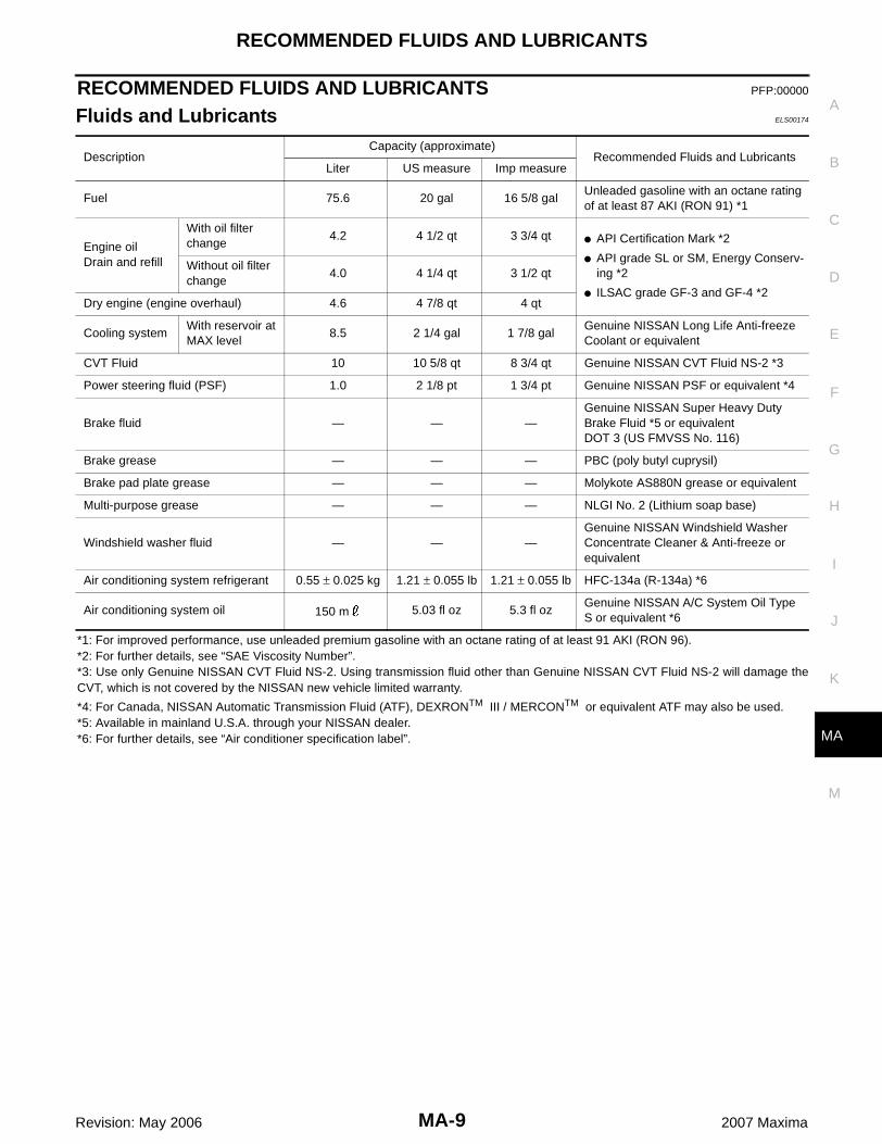
Fluids and Lubricants ELS00174
*1: For improved performance, use unleaded premium gasoline with an octane rating of at least 91 AKI (RON 96).*2: For further details, see “SAE Viscosity Number”.*3: Use only Genuine NISSAN CVT Fluid NS-2. Using transmission fluid other than Genuine NISSAN CVT Fluid NS-2 will damage theCVT, which is not covered by the NISSAN new vehicle limited warranty.
*4: For Canada, NISSAN Automatic Transmission Fluid (ATF), DEXRONTM III / MERCONTM or equivalent ATF may also be used.*5: Available in mainland U.S.A. through your NISSAN dealer.*6: For further details, see “Air conditioner specification label”.
DescriptionCapacity (approximate)
Recommended Fluids and LubricantsLiter US measure Imp measure
Fuel 75.6 20 gal 16 5/8 galUnleaded gasoline with an octane rating of at least 87 AKI (RON 91) *1
Engine oilDrain and refill
With oil filter change
4.2 4 1/2 qt 3 3/4 qt � API Certification Mark *2
� API grade SL or SM, Energy Conserv-ing *2
� ILSAC grade GF-3 and GF-4 *2
Without oil filter change
4.0 4 1/4 qt 3 1/2 qt
Dry engine (engine overhaul) 4.6 4 7/8 qt 4 qt
Cooling systemWith reservoir at MAX level
8.5 2 1/4 gal 1 7/8 galGenuine NISSAN Long Life Anti-freeze Coolant or equivalent
CVT Fluid 10 10 5/8 qt 8 3/4 qt Genuine NISSAN CVT Fluid NS-2 *3
Power steering fluid (PSF) 1.0 2 1/8 pt 1 3/4 pt Genuine NISSAN PSF or equivalent *4
Brake fluid — — —Genuine NISSAN Super Heavy Duty Brake Fluid *5 or equivalentDOT 3 (US FMVSS No. 116)
Brake grease — — — PBC (poly butyl cuprysil)
Brake pad plate grease — — — Molykote AS880N grease or equivalent
Multi-purpose grease — — — NLGI No. 2 (Lithium soap base)
Windshield washer fluid — — —Genuine NISSAN Windshield Washer Concentrate Cleaner & Anti-freeze or equivalent
Air conditioning system refrigerant 0.55 ± 0.025 kg 1.21 ± 0.055 lb 1.21 ± 0.055 lb HFC-134a (R-134a) *6
Air conditioning system oil 150 m 5.03 fl oz 5.3 fl ozGenuine NISSAN A/C System Oil Type S or equivalent *6

MA-10
RECOMMENDED FLUIDS AND LUBRICANTS
Revision: May 2006 2007 Maxima
SAE Viscosity Number ELS00175
GASOLINE ENGINE OIL� SAE 5W-30 viscosity oil is preferred for all temperatures. SAE
10W-30 and 10W-40 viscosity oil may be used if the ambienttemperature is above -18°C (0°F).
� Use of 5W-30 viscosity oil will increase fuel economy.
ANTI-FREEZE COOLANT MIXTURE RATIOThe engine cooling system is filled at the factory with a high-quality, long life, year-round, anti-freeze coolantsolution. The anti-freeze solution contains rust and corrosion inhibitors. Therefore, additional cooling systemadditives are not necessary.
CAUTION:� When adding or replacing coolant, be sure to use only Genuine NISSAN anti-freeze coolant or
equivalent with the proper mixture ratio of 50% anti-freeze and 50% demineralized water or dis-tilled water.
� Other types of coolant solutions may damage your cooling system.
MMA117AA
Protection for outside temperatures down to Genuine NISSAN Long life Anti-freeze Coolant
Demineralized water or dis-tilled water°C °F
– 35 – 30 50% 50%

ENGINE MAINTENANCE
MA-11
C
D
E
F
G
H
I
J
K
M
A
B
MA
Revision: May 2006 2007 Maxima
ENGINE MAINTENANCE PFP:00000
Drive Belts ELS00176
CHECKING DRIVE BELTS
WARNING:Inspect and check the drive belts with the engine off.1. Inspect belt for cracks, fraying, wear or oil adhesion. If necessary, replace with a new one.2. Inspect drive belt deflections by pushing on the belt midway between pulleys as shown.3. Rotate the crankshaft pulley two times then check the belt tension using Tool.
NOTE:� Inspect drive belt deflection or tension when engine is cold.� Adjust if belt deflections exceed the limit or if belt tension is not within specifications.
Belt Deflection and Tension
*: If belt tension gauge cannot be installed at check points shown, check drive belt tension at different location on the belt.
TENSION ADJUSTMENT
CAUTION:� When belt is replace with a new one, adjust it to value for “New belt” to accommodate for insuffi-
cient adaptability with pulley grooves.
LBIA0076E
Tool number : — (BT-3373-F)
Deflection adjustment Unit: mm (in) Tension adjustment* Unit: N (kg, lb)
Used beltNew belt
Used beltNew belt
Limit After adjustment Limit After adjustment
Alternator and air conditioning compressor
7 (0.28)4.2 - 4.6
(0.17 - 0.18)3.7 - 4.1
(0.15 - 0.16)294 (30, 66)
730 - 818(74.5 - 83.5,164 - 184)
838 - 926(85.5 - 94.5,188 - 208)
Power steering pump
11 (0.43)7.3 - 8.0
(0.29 - 0.31)6.5 - 7.2
(0.26 - 0.28)196 (20, 44)
495 - 583(50.5 - 59.5,111 - 131)
603 - 691(61.5 - 70.5,
135.6 - 155.4)
Applied pushing force
98 N (10 kg, 22 lb) —
Portion Belt tightening method for adjustment
Power steering oil pump belt Adjusting bolt on power steering oil pump
Generator and air conditioner compressor belt Adjusting bolt on idler pulley

MA-12
ENGINE MAINTENANCE
Revision: May 2006 2007 Maxima
� When deflection or tension of belt being used exceeds “Used belt limit” adjust it to value for“Used belt”.
� When checking belt deflection or tension immediately after installation, first adjust it to the speci-fication value. Then, after turning the crankshaft two turns or more, readjust to the specified valueto avoid variation in deflection between pulleys.
� When installing belt, make sure that it is correctly engaged with pulley groove.� Keep oil and water away from belt.� Do not twist or bend belt excessively.
Generator and Air Conditioner Compressor Belt1. Remove engine undercover.2. Loosen idler pulley lock nut (A) and adjust by turning adjusting
bolt (B).� For specified belt tension, refer to MA-11, "Drive Belts" .
3. Tighten lock nut (A) to specification.4. Tighten adjusting bolt (B) to specification.
Power Steering Oil Pump Belt1. Remove engine undercover.
WBIA0324E

ENGINE MAINTENANCE
MA-13
C
D
E
F
G
H
I
J
K
M
A
B
MA
Revision: May 2006 2007 Maxima
2. Loosen adjusting bolt (C).3. Loosen power steering oil pump bolt (D).
NOTE:Bolt head (D) is at the engine rear side.
4. Adjust by turning the adjusting bolt (E).� For specified belt tension, refer to MA-11, "Drive Belts" .NOTE:Adjusting bolt (E) is loosened with counterclockwise rotation.
5. Tighten adjusting bolt (C) to specification.6. Tighten power steering oil pump bolt (D) to specification.
Changing Engine Coolant ELS00177
WARNING:� To avoid being scalded, never change the coolant when the engine is hot.� Wrap a thick cloth around cap and carefully remove the cap. First, turn the cap a quarter of a turn
to release built-up pressure. Then turn the cap all the way.
DRAINING ENGINE COOLANT1. Remove engine undercover.2. Open radiator drain plug at the bottom of radiator and remove
the radiator filler cap. This is the only step required for a partialcooling system drain.
3. For a complete cooling system drain, remove the reservoir tankand drain the coolant, and then clean the reservoir tank beforeinstallation.� Do not allow coolant to spill on the drive belts.
4. When performing a complete cooling system drain (to removethe engine or for engine repair), remove the water drain plug(water pump side) and the water drain plug.
5. Check the drained coolant for contaminants such as rust, corro-sion or discoloration.� If contaminated, flush the engine cooling system. Refer to MA-14, "FLUSHING COOLING SYSTEM" .
REFILLING ENGINE COOLANT1. Install the radiator drain plug. If the cooling system was drained completely, install the reservoir tank and
the water drain plugs.� The radiator must be completely empty of coolant and water.� Apply sealant to the threads of the water drain plugs. Use Genuine High Performance Thread Sealant
or equivalent. Refer to GI-46, "RECOMMENDED CHEMICAL PRODUCTS AND SEALANTS" .
2. If disconnected, reattach the upper radiator hose at the engine side.
WBIA0324E
LBIA0063E
Radiator drain plug : Refer to CO-13, "RADIATOR" .Water drain plug (water pump side) : Refer to EM-113, "CYLINDER BLOCK" .Water drain plug : Refer to EM-113, "CYLINDER BLOCK" .
MA-14
ENGINE MAINTENANCE
Revision: May 2006 2007 Maxima
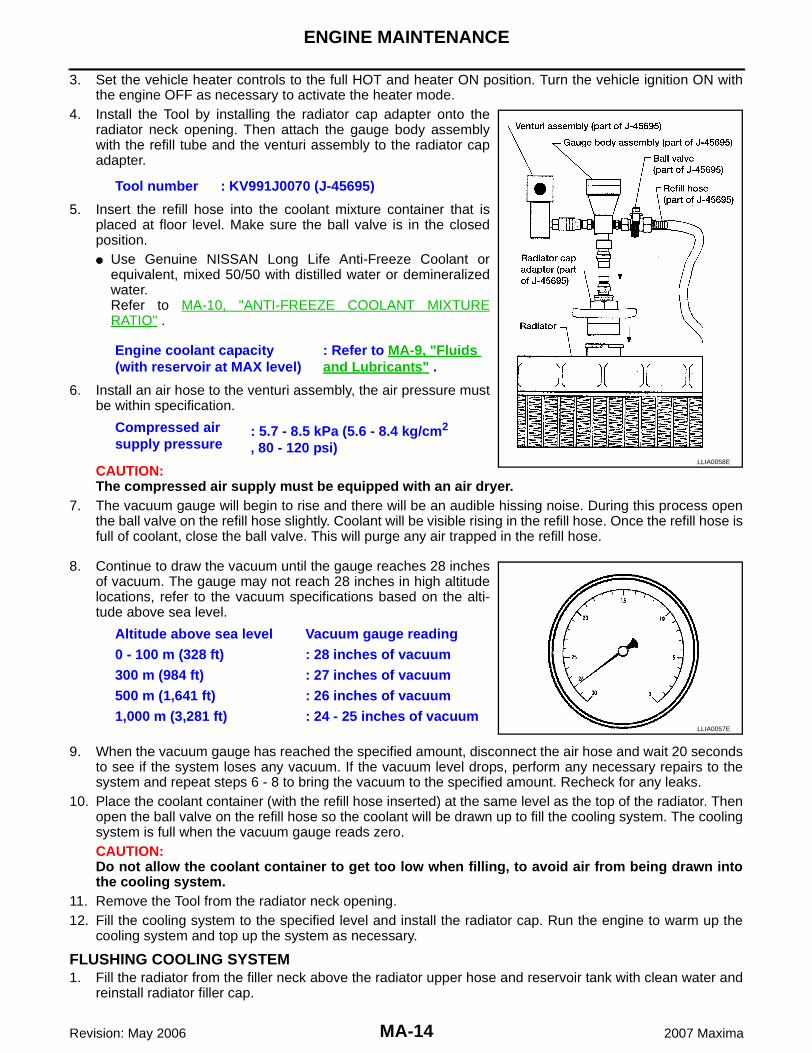
3. Set the vehicle heater controls to the full HOT and heater ON position. Turn the vehicle ignition ON withthe engine OFF as necessary to activate the heater mode.
4. Install the Tool by installing the radiator cap adapter onto theradiator neck opening. Then attach the gauge body assemblywith the refill tube and the venturi assembly to the radiator capadapter.
5. Insert the refill hose into the coolant mixture container that isplaced at floor level. Make sure the ball valve is in the closedposition. � Use Genuine NISSAN Long Life Anti-Freeze Coolant or
equivalent, mixed 50/50 with distilled water or demineralizedwater.Refer to MA-10, "ANTI-FREEZE COOLANT MIXTURERATIO" .
6. Install an air hose to the venturi assembly, the air pressure mustbe within specification.
CAUTION:The compressed air supply must be equipped with an air dryer.
7. The vacuum gauge will begin to rise and there will be an audible hissing noise. During this process openthe ball valve on the refill hose slightly. Coolant will be visible rising in the refill hose. Once the refill hose isfull of coolant, close the ball valve. This will purge any air trapped in the refill hose.
8. Continue to draw the vacuum until the gauge reaches 28 inchesof vacuum. The gauge may not reach 28 inches in high altitudelocations, refer to the vacuum specifications based on the alti-tude above sea level.
9. When the vacuum gauge has reached the specified amount, disconnect the air hose and wait 20 secondsto see if the system loses any vacuum. If the vacuum level drops, perform any necessary repairs to thesystem and repeat steps 6 - 8 to bring the vacuum to the specified amount. Recheck for any leaks.
10. Place the coolant container (with the refill hose inserted) at the same level as the top of the radiator. Thenopen the ball valve on the refill hose so the coolant will be drawn up to fill the cooling system. The coolingsystem is full when the vacuum gauge reads zero.CAUTION:Do not allow the coolant container to get too low when filling, to avoid air from being drawn intothe cooling system.
11. Remove the Tool from the radiator neck opening.12. Fill the cooling system to the specified level and install the radiator cap. Run the engine to warm up the
cooling system and top up the system as necessary.
FLUSHING COOLING SYSTEM1. Fill the radiator from the filler neck above the radiator upper hose and reservoir tank with clean water and
reinstall radiator filler cap.
Tool number : KV991J0070 (J-45695)
Engine coolant capacity (with reservoir at MAX level)
: Refer to MA-9, "Fluids and Lubricants" .
Compressed air supply pressure
: 5.7 - 8.5 kPa (5.6 - 8.4 kg/cm2 , 80 - 120 psi)
LLIA0058E
Altitude above sea level Vacuum gauge reading0 - 100 m (328 ft) : 28 inches of vacuum300 m (984 ft) : 27 inches of vacuum500 m (1,641 ft) : 26 inches of vacuum1,000 m (3,281 ft) : 24 - 25 inches of vacuum
LLIA0057E

ENGINE MAINTENANCE
MA-15
C
D
E
F
G
H
I
J
K
M
A
B
MA
Revision: May 2006 2007 Maxima
2. Run the engine and warm it up to normal operating temperature.3. Rev the engine two or three times under no-load.4. Stop the engine and wait until it cools down.5. Drain the water from the system. Refer to MA-13, "DRAINING ENGINE COOLANT" .6. Repeat steps 1 through 5 until clear water begins to drain from the radiator.
Checking Fuel Lines ELS00178
Inspect the fuel lines and fuel tank for improper hose attachment,leaks, cracks, damage, loose connections, chafing, or deterioration.If necessary, repair or replace faulty parts.
Changing Air Cleaner Filter ELS00179
VISCOUS PAPER TYPENOTE:The viscous paper type filter does not need cleaning between replacement intervals. Refer to MA-6, "PERI-ODIC MAINTENANCE" .1. Unhook the air cleaner case side clips and remove the air cleaner case (upper).2. Remove the air cleaner filter.3. Install a new air cleaner filter.4. Installation of the remaining components is in the reverse order
of removal.
Changing Engine Oil ELS0017A
WARNING:� Be careful not to burn yourself, as the engine oil is hot.� Prolonged and repeated contact with used engine oil may cause skin cancer; try to avoid direct
skin contact with used oil. If skin contact is made, wash thoroughly with soap or hand cleaner assoon as possible.
1. Position the vehicle so it is level on the hoist.2. Warm up the engine, and check for oil leaks from the engine.3. Stop the engine and wait at least 10 minutes.4. Remove the oil drain plug and oil filler cap.5. Drain the engine oil. 6. Install the oil drain plug using a new washer.
CAUTION:� Clean the oil drain plug and use a new washer for installation.
7. Refill the engine with the specified new engine oil. Refer to MA-9, "RECOMMENDED FLUIDS ANDLUBRICANTS" .
SMA803A
LLIA0016E
Oil pan drain plug : Refer to EM-31, "OIL PAN AND OIL STRAINER" .
MA-16
ENGINE MAINTENANCE
Revision: May 2006 2007 Maxima
CAUTION:� The refill oil capacity depends on the oil temperature and drain time. Use the capacity specifica-
tions for reference only.� Always use the dipstick to determine when the proper amount of oil is in the engine.
8. Start the engine and run it at idle to warm up, then check the area around the oil drain plug and oil filter forany oil leaks.
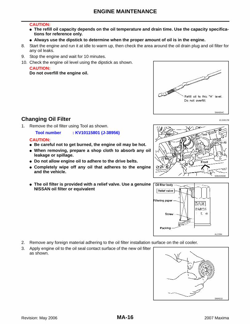
9. Stop the engine and wait for 10 minutes.10. Check the engine oil level using the dipstick as shown.
CAUTION:Do not overfill the engine oil.
Changing Oil Filter ELS0017B
1. Remove the oil filter using Tool as shown.
CAUTION:� Be careful not to get burned, the engine oil may be hot.� When removing, prepare a shop cloth to absorb any oil
leakage or spillage.� Do not allow engine oil to adhere to the drive belts.� Completely wipe off any oil that adheres to the engine
and the vehicle.
� The oil filter is provided with a relief valve. Use a genuineNISSAN oil filter or equivalent
2. Remove any foreign material adhering to the oil filter installation surface on the oil cooler.3. Apply engine oil to the oil seal contact surface of the new oil filter
as shown.
SMA954C
Tool number : KV10115801 (J-38956)
WBIA0590E
ALC094
SMA010
ENGINE MAINTENANCE
MA-17
C
D
E
F
G
H
I
J
K
M
A
B
MA
Revision: May 2006 2007 Maxima
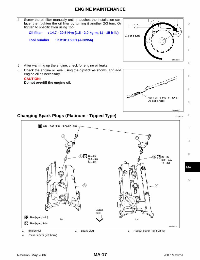
4. Screw the oil filter manually until it touches the installation sur-face, then tighten the oil filter by turning it another 2/3 turn. Ortighten to specification using Tool.
5. After warming up the engine, check for engine oil leaks.6. Check the engine oil level using the dipstick as shown, and add
engine oil as necessary.CAUTION:Do not overfill the engine oil.
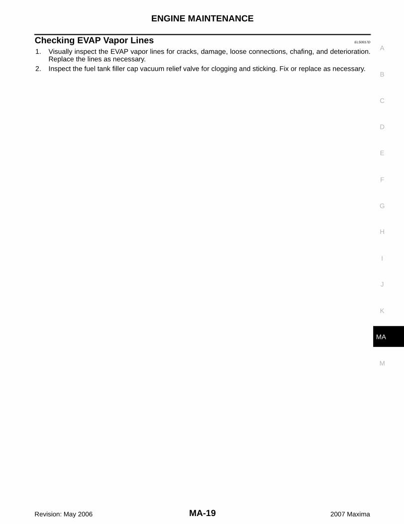
Changing Spark Plugs (Platinum - Tipped Type) ELS0017C
Oil filter : 14.7 - 20.5 N·m (1.5 - 2.0 kg-m, 11 - 15 ft-lb)
Tool number : KV10115801 (J-38956)
SMA229B
SMA954C
1. Ignition coil 2. Spark plug 3. Rocker cover (right bank)
4. Rocker cover (left bank)
WBIA0264E

MA-18
ENGINE MAINTENANCE
Revision: May 2006 2007 Maxima
REMOVAL1. Remove the intake manifold collector, gasket, and electric throttle control actuator. Refer to EM-18,
"INTAKE MANIFOLD COLLECTOR" .2. Remove the six ignition coils.
CAUTION:Do not shock it.
3. Remove the six spark plugs using a suitable tool.� If replacing the spark plugs use the correct spark plug for
maximum performance.
INSPECTION AFTER REMOVAL� Do not use a wire brush for cleaning the spark plug tip.
� If the spark plug tip is covered with carbon, a spark plug cleaner may be used.
� Checking and adjusting the spark plug gap is not requiredbetween change intervals. If the gap is out of specification,replace the spark plug.
INSTALLATIONInstallation is in the reverse order of removal.
Spark Plug Type
SEM294A
SMA673B
Cleaner air pressure : Less than 588 kPa (6 kg/cm2 , 85 psi)Cleaning time : Less than 20 seconds
Gap (nominal) : 1.1 mm (0.043 in)
SMA806CA
Make NGK
Part number DILFR5A11
Gap (nominal) 1.1 mm (0.043 in)
ENGINE MAINTENANCE
MA-19
C
D
E
F
G
H
I
J
K
M
A
B
MA
Revision: May 2006 2007 Maxima
Checking EVAP Vapor Lines ELS0017D
1. Visually inspect the EVAP vapor lines for cracks, damage, loose connections, chafing, and deterioration.Replace the lines as necessary.
2. Inspect the fuel tank filler cap vacuum relief valve for clogging and sticking. Fix or replace as necessary.

MA-20
CHASSIS AND BODY MAINTENANCE
Revision: May 2006 2007 Maxima
CHASSIS AND BODY MAINTENANCE PFP:00100
Changing In-cabin Microfilter ELS001O5
1. Remove the glove box pins. Refer to IP-15, "Glove Box Assembly and Housing" .2. Press in the sides of the glove box door to release the glove box door from the glove box housing.3. Disconnect the glove box damper cord to remove the glove box door.4. Disengage the two filter cover tabs to remove the filter cover.5. Remove the in-cabin microfilter from the blower unit.6. Install the new in-cabin microfilter into the blower unit.
CAUTION:� Insert the new filter with the “UP” arrow in the correct ori-
entation.� Insert the new filter with the “UP” arrow side of the filter
facing the rear of the vehicle.7. Install the filter cover on the blower unit.8. Connect the glove box damper cord to the glove box door.9. Press in the sides of the glove box door to install the glove box
door into the glove box housing.10. Install the glove box pins.
Checking Exhaust System ELS0017E
Check the exhaust pipes, muffler, and exhaust mounts for improperattachment, leaks, cracks, damage, chafing, or deterioration.
Checking CVT Fluid ELS001YJ
FLUID LEVEL CHECKFluid level should be checked with the fluid warmed up to 50° – 80°C (122° – 176°F).1. Check for fluid leakage.2. With the engine warmed up, drive the vehicle to warm up the
CVT fluid. When ambient temperature is 20°C (68°F), it takesabout 10 minutes for the CVT fluid to warm up to 50° – 80°C(122° – 176°F).
3. Park the vehicle on a level surface and set the parking brake.4. With engine at idle, while depressing brake pedal, move the
selector lever throughout the entire shift range and return it tothe “P” position.
LJIA0013E
SMA211A
SMA146B
CHASSIS AND BODY MAINTENANCE
MA-21
C
D
E
F
G
H
I
J
K
M
A
B
MA
Revision: May 2006 2007 Maxima
5. Press the tab on the CVT fluid level gauge to release the lockand pull out the CVT fluid level gauge from the CVT fluid charg-ing pipe.
6. Wipe fluid off the CVT fluid level gauge. Then rotate the CVTfluid level gauge 180° and re-insert it into the CVT charging pipeas far as it will go.CAUTION:Always use lint free paper towels to wipe fluid off the CVTfluid level gauge.
7. Remove the CVT fluid level gauge and check that the fluid levelis within the specified range as shown. If the fluid level is at orbelow the low side of the range, add the necessary specifiedNISSAN CVT fluid through the CVT charging pipe.
CAUTION:� Only use specified NISSAN CVT fluid.� Do not overfill the CVT.
8. Install the CVT fluid level gauge to the CVT fluid charging pipe until it locks.CAUTION:When CVT fluid level gauge is installed into the CVT fluid charging pipe, make sure that the CVTfluid level gauge is securely locked in place.
FLUID CONDITION CHECK
Changing CVT Fluid ELS001ZF
1. Warm up CVT fluid by driving the vehicle for 10 minutes.2. Drain CVT fluid from CVT fluid cooler hose (return side) and refill with new specified NISSAN CVT fluid in
the CVT fluid charging pipe with the engine running at idle speed.
SCIA1933E
SCIA1931E
Fluid grade: Refer to MA-9, "Fluids and Lubricants" .
SCIA1932E
Fluid status Conceivable cause Required operation
Varnished (viscous varnish state)
Clutch, brake scorched
Replace the CVT fluid and check the CVT main unit and the vehicle for malfunctions (wire harness, cooler pipes, etc.)
Milky white or cloudy
Water in the fluid Replace the CVT fluid and check for places where water is getting in.
Large amount of metal powder mixed in fluid
Unusual wear of sliding parts within CVT
Replace the CVT fluid and check for improper operation of the CVT.
ATA0022D
Fluid capacity and grade : Refer to MA-9, "Fluids and Lubricants" .
MA-22
CHASSIS AND BODY MAINTENANCE
Revision: May 2006 2007 Maxima
CAUTION:Only use the specified NISSAN CVT fluid.
3. Refill until new CVT fluid comes out from CVT fluid cooler hose (return side).NOTE:About 30 - 50% extra fluid will be required for this procedure.
4. Check fluid level and condition. Refer to CVT-15, "Checking CVT Fluid" .CAUTION:Delete CVT fluid deterioration date with CONSULT-II after changing CVT fluid. Refer to CVT-56,"Check CVT Fluid Deterioration Date" .
Balancing Wheels (Bonding Weight Type) ELS0017K
REMOVAL1. Remove the inner and outer balance weights from the wheel.
CAUTION:Be careful not to scratch the wheel during removal.
2. Use a releasing agent to remove the double-faced adhesive tape from the wheel.CAUTION:� Be careful not to scratch the wheel during removal.� After removing the double-faced adhesive tape, wipe off any traces of the releasing agent from
the wheel.
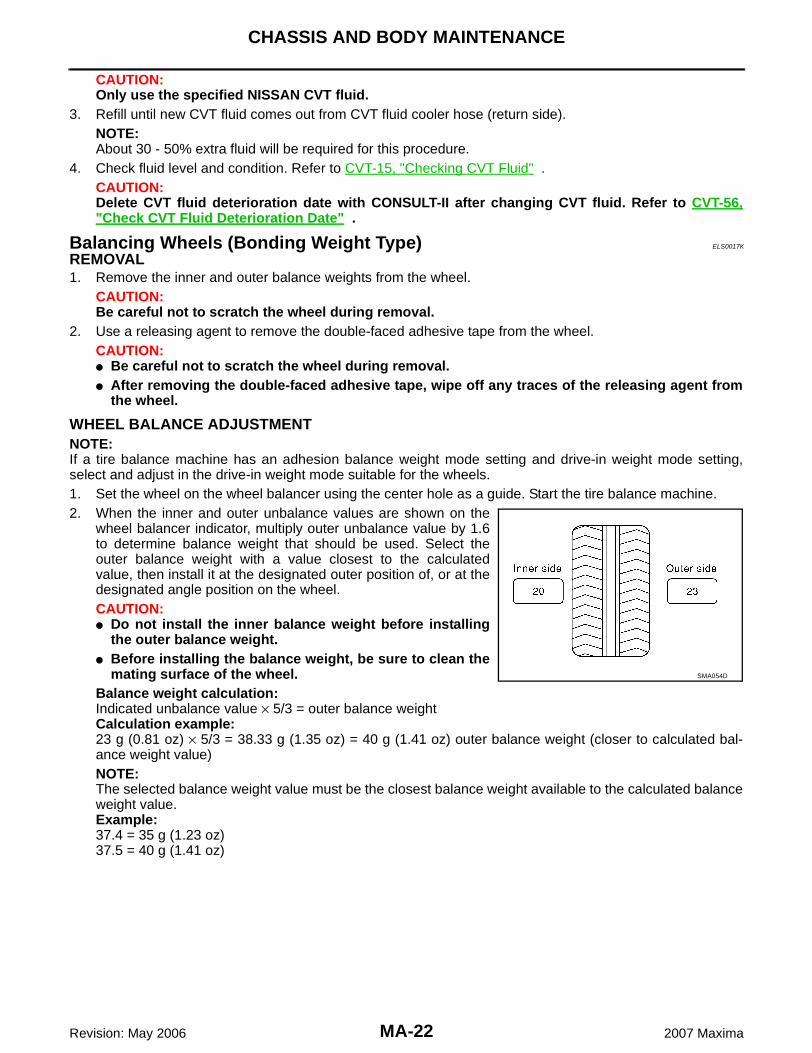
WHEEL BALANCE ADJUSTMENT NOTE:If a tire balance machine has an adhesion balance weight mode setting and drive-in weight mode setting,select and adjust in the drive-in weight mode suitable for the wheels.1. Set the wheel on the wheel balancer using the center hole as a guide. Start the tire balance machine.2. When the inner and outer unbalance values are shown on the
wheel balancer indicator, multiply outer unbalance value by 1.6to determine balance weight that should be used. Select theouter balance weight with a value closest to the calculatedvalue, then install it at the designated outer position of, or at thedesignated angle position on the wheel.CAUTION:� Do not install the inner balance weight before installing
the outer balance weight.� Before installing the balance weight, be sure to clean the
mating surface of the wheel.Balance weight calculation:Indicated unbalance value × 5/3 = outer balance weightCalculation example:23 g (0.81 oz) × 5/3 = 38.33 g (1.35 oz) = 40 g (1.41 oz) outer balance weight (closer to calculated bal-ance weight value)NOTE:The selected balance weight value must be the closest balance weight available to the calculated balanceweight value.Example:37.4 = 35 g (1.23 oz)37.5 = 40 g (1.41 oz)
SMA054D

CHASSIS AND BODY MAINTENANCE
MA-23
C
D
E
F
G
H
I
J
K
M
A
B
MA
Revision: May 2006 2007 Maxima
a. Install the balance weight in the position as shown.b. When installing the balance weight to the wheels, set it into the
grooved area on the inner wall of the wheel as shown, so thatthe balance weight center is aligned with the wheel balancerindication position (angle).CAUTION:� Always use genuine NISSAN adhesion balance weights.� Balance weights are not reusable; always replace with
new ones.� Do not install more than three sheets of balance weight.
c. If calculated balance weight value exceeds 50 g (1.76 oz), installtwo balance weight sheets in line with each other.CAUTION:Do not install one balance weight sheet on top of another.
3. Start the wheel balancer.4. Install the drive-in balance weight on the inner side of the wheel in the wheel balancer indication position
(angle).CAUTION:Do not install more than two balance weights in one position (angle).
5. Start the wheel balancer. Make sure that the inner and outer residual unbalance values are 5 g (0.18 oz)each or less.� If either residual unbalance value exceeds 5 g (0.18 oz), repeat the installation procedures.
Wheel Balance (Maximum Allowable Unbalance)
Tire Rotation ELS0017L
� Follow the maintenance schedule for tire rotation service intervals. Refer to MA-6, "PERIODIC MAINTE-NANCE" .
SMA055D
SMA056D
Maximum allowable unbalanceDynamic (at rim flange) 5 g (0.18 oz) (one side)
Static 10 g (0.35 oz)

MA-24
CHASSIS AND BODY MAINTENANCE
Revision: May 2006 2007 Maxima
� Do not include the T-type spare tire when rotating the tires asshown.
� Tighten wheel nuts to specification.CAUTION:When installing wheels, tighten them diagonally by dividingthe work two to three times in order to prevent the wheelsfrom developing any distortion.
� After rotating the tires as shown, adjust the tire pressure.
Checking Brake Fluid Level and Leaks ELS0017M
� Check the brake fluid level in the reservoir tank. It should bebetween the “Max” and “Min” lines on the reservoir tank.
� Visually check around the reservoir tank for leaks.� If the brake fluid level is extremely low or below the “Min” level,
check the brake system for leaks.NOTE:If brake warning lamp is on, release parking brake lever and see ifbrake warning lamp goes off. If not, check brake system for leaks.
Checking Brake Lines and Cables ELS0017N
CAUTION:If leakage occurs around hose and tube connections, retighten or, if necessary, replace damagedparts.1. Check the brake lines (tubes and hoses) and parking brake
cables for improper attachment, leaks, chafing, abrasions, dete-rioration, and damage. Repair or replace parts as necessary.
2. Apply a stepping force of 784 N (80 kg-f, 176 lb-f) to the brakepedal with the engine running and keep it for about 5 seconds,then check each part for leaks.
Wheel nut : Refer to WT-6, "WHEEL AND TIRE ASSEMBLY" .
SMA829C
LFIA0096E
SBR389C

CHASSIS AND BODY MAINTENANCE
MA-25
C
D
E
F
G
H
I
J
K
M
A
B
MA
Revision: May 2006 2007 Maxima
Checking Disc Brake ELS0017O
ROTORCheck the rotor condition and thickness. Resurface or replace therotor as necessary. Refer to BR-37, "Disc Brake" .
CALIPERCheck the caliper for leaks.
PADCheck the brake pads for wear or damage. Refer to BR-37, "DiscBrake" .
Checking Steering Gear and Linkage ELS0017P
STEERING GEAR� Check the gear housing and boots for looseness, damage and power steering fluid leaks.� Check the power steering hose connections for leaks.� Check the steering column for looseness.
STEERING LINKAGECheck the ball joint, dust cover and other component parts for looseness, wear, damage and grease leakage.
SMA260A
SMA922A
BRA0010D

MA-26
CHASSIS AND BODY MAINTENANCE
Revision: May 2006 2007 Maxima
Checking Power Steering Fluid and Lines ELS0017Q
CHECKING FLUID LEVELCheck the power steering fluid level in the reservoir tank with theengine off. Use the “HOT” range at fluid temperatures of 50° - 80°C (122° -176°F) or the “COLD” range at fluid temperatures of 0° - 30°C (32° -86°F).CAUTION:� Do not overfill the power steering reservoir tank.� Use the recommended power steering fluid. Refer to MA-9,
"Fluids and Lubricants" .
CHECKING FLUID LEAKAGECheck the power steering hoses for improper attachment, leaks, cracks, damage, loose connections, chafingand deterioration.
1. Run the engine between idle speed and 1,000 rpm. Make sure the temperature of the power steering fluidin the reservoir tank rises to 60° to 80°C (140° to 176°F).
2. Turn the steering wheel right-to-left several times.3. Hold the steering wheel at each lock position for five seconds and carefully check for fluid leaks.
CAUTION:Do not hold the steering wheel in a locked position for more than 15 seconds.
4. If fluid leaks at the connectors is noted, loosen the flare nut and then retighten it.CAUTION:Do not overtighten the connector as this can damage the O-ring, washer, and connector.
5. If fluid leaks from the power steering pump are noted, check the power steering oil pump. Refer to PS-29,"Inspection After Disassembly" .
6. Check the steering gear boots for accumulation of power steering fluid indicating a steering gear leak.
LGIA0021E
WGIA0039E

CHASSIS AND BODY MAINTENANCE
MA-27
C
D
E
F
G
H
I
J
K
M
A
B
MA
Revision: May 2006 2007 Maxima
Axle and Suspension Parts ELS0017R
Check the front and rear axle and suspension parts for excessiveplay, cracks, wear, or other damage.� Shake each wheel as shown to check for excessive play.� Rotate each wheel to check for abnormal noise.
� Check the strut mount nuts for looseness.
� Check the axle and suspension nuts and bolts for looseness.
� Check the struts for oil leakage or other damage.� Check suspension ball joint for grease leakage and ball joint
dust cover for cracks or other damage.
SMA525A
SMA614
LLIA0019E
SFA392B
MA-28
CHASSIS AND BODY MAINTENANCE
Revision: May 2006 2007 Maxima
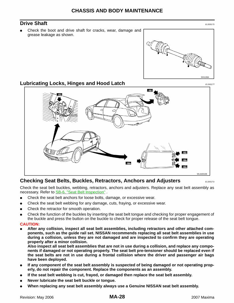
Drive Shaft ELS0017S
� Check the boot and drive shaft for cracks, wear, damage andgrease leakage as shown.
Lubricating Locks, Hinges and Hood Latch ELS0017T
Checking Seat Belts, Buckles, Retractors, Anchors and Adjusters ELS0017U
Check the seat belt buckles, webbing, retractors, anchors and adjusters. Replace any seat belt assembly asnecessary. Refer to SB-6, "Seat Belt Inspection" .� Check the seat belt anchors for loose bolts, damage, or excessive wear. � Check the seat belt webbing for any damage, cuts, fraying, or excessive wear.� Check the retractor for smooth operation.� Check the function of the buckles by inserting the seat belt tongue and checking for proper engagement of
the buckle and press the button on the buckle to check for proper release of the seat belt tongue.CAUTION:� After any collision, inspect all seat belt assemblies, including retractors and other attached com-
ponents, such as the guide rail set. NISSAN recommends replacing all seat belt assemblies in useduring a collision, unless they are not damaged and are inspected to confirm they are operatingproperly after a minor collision.Also inspect all seat belt assemblies that are not in use during a collision, and replace any compo-nents if damaged or not operating properly. The seat belt pre-tensioner should be replaced even ifthe seat belts are not in use during a frontal collision where the driver and passenger air bagshave been deployed.
� If any component of the seat belt assembly is suspected of being damaged or not operating prop-erly, do not repair the component. Replace the components as an assembly.
� If the seat belt webbing is cut, frayed, or damaged then replace the seat belt assembly.� Never lubricate the seat belt buckle or tongue.� When replacing any seat belt assembly always use a Genuine NISSAN seat belt assembly.
SFA108A
WLIA0010E