l a b q(t=0)=1p c +q r c = 100 nf c i l = 500 -q = 40 c · is the rate of change of current or ......
TRANSCRIPT

Discussion Question 11A Physics 212 week 11
RLC Preview
You will learn much more about RLC circuits in the next lecture but here is a preview of their interesting behavior. In this circuit, an initial charge of Q 0 =1PC is placed on the capacitor. At time t=0 the switch is closed.
L
R
Q(t=0)=1PCC = 100 nFL = 500 PHR = 40 :
C+Q
-QI
A
C
B
L
R
Q(t=0)=1PCC = 100 nFL = 500 PHR = 40 :
C+Q
-QI
A
C
B
The charge on the capacitor oscillates while dying out as shown below:
Q
t
Q
t
Our conventions are that I is positive when flowing in the direction of the arrow, and Q is positive when the top plate of the capacitor is positive and the bottom plate is negative as illustrated.
(a) Immediately after the switch is thrown, what is the current I (0+)?
Right before the switch is thrown I = 0 .The inductor resists an immediate change in current so the current will be 0 immediately after the switch is thrown.
(b) Immediately after the switch is thrown, what is the voltage drop across the inductor, and what is the rate of change of current or dI/dt (0+) ? Hints: What is the voltage drop across the capacitor? What must the voltage drop across the inductor be according to KVL? How does the voltage drop across an inductor depend on dI/dt ?
0cap
L
1The voltage increase across the capacitor is V 10 V.0 1
Applying KVL (clockwise from lower plate) we have: 10 - 0where is voltage drop across inductor:
or 10 - V = 0
L
L
Q CC . F
V - IRV
PP
'
''
'
L L10 VV 10 V. V 20 kA/s
500
HdI dILdt dt P
o ' ' o �
Discussion Question 11A Physics 212 week 11
RLC Preview
L
R
Q(t=0)=1PCC = 100 nFL = 500 PHR = 40 :
C+Q
-QI
A
C
B
L
R
Q(t=0)=1PCC = 100 nFL = 500 PHR = 40 :
C+Q
-QI
A
C
B
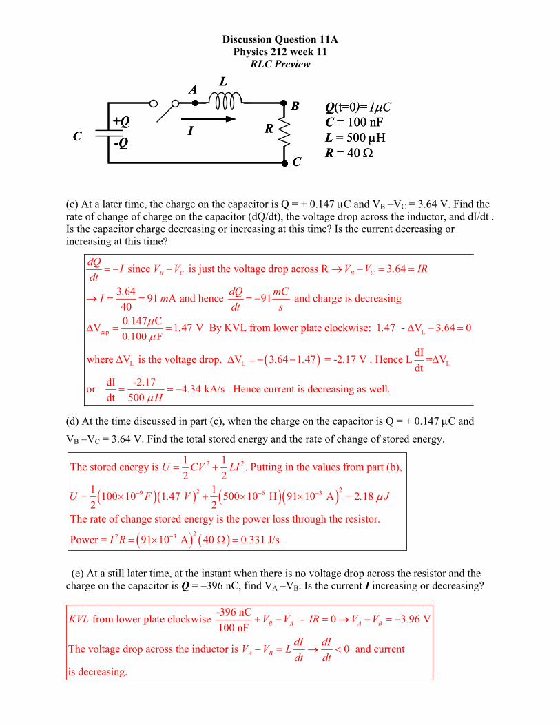
(c) At a later time, the charge on the capacitor is Q = + 0.147 PC and VB –VC = 3.64 V. Find the rate of change of charge on the capacitor (dQ/dt), the voltage drop across the inductor, and dI/dt . Is the capacitor charge decreasing or increasing at this time? Is the current decreasing or increasing at this time?
cap
since is just the voltage drop across R 3 64
3 64 91 and hence 91 and charge is decreasing 400 147 CV 1 47 V By KVL from lower plate clockwise: 1 470.100 F
B C B CdQ I V V V V . IRdt
. dQ mCI mdt s
. . .PP
� � o �
o $ �
'
� �
L
L L
- V 3 64 0
dIwhere V is the voltage drop. V 3 64 1 47 = -2.17 V . Hence L = Vdt
dI -2.17 or 4 34 kA/s . Hence current is decreasing as well.dt 500
.
. .
.HP
' �
' ' � �
�
L'
(d) At the time discussed in part (c), when the charge on the capacitor is Q = + 0.147 PC and VB –VC = 3.64 V. Find the total stored energy and the rate of change of stored energy.
� �� � � �� �
2 2
229 6 3
1 1The stored energy is Putting in the values from part (b), 2 2
1 1100 10 1 47 500 10 H 91 10 A 2 18 2 2
The rate of change stored energy is the power loss through the resistor.
Powe
P� � �
�
u � u u
U CV LI .
U F . V .
� � � �
J
22 3r = 91 10 A 40 0 331 J/s� u : I R .
(e) At a still later time, at the instant when there is no voltage drop across the resistor and the charge on the capacitor is Q = –396 nC, find VA –VB. Is the current I increasing or decreasing?
-396 nC from lower plate clockwise 0 3 96 V100 nF
The voltage drop across the inductor is 0 and current
is decreasing.
B A A B
A B
KVL V V - IR V V .
dI dIV V Ldt dt
� � o � �
� o �

Discussion Question 11B Physics 212 week 11
LC Circuits
At right, we see the classic LC circuit, consisting of an inductor in series with a capacitor. To be precise, this is an undriven LC circuit, since there is no battery driving the flow of current. Nevertheless, this simple circuit has an amazing and highly useful property: it supports a resonant oscillation of current. In the ideal case shown here where there is no resistance in the circuit, the oscillation can continue indefinitely without any external source of EMF to drive it. LC circuits often appear as parts of larger networks which are designed to operate at a particular frequency. The most familiar example is a radio, whose circuitry can be tuned to receive (i.e. respond to) incoming electromagnetic waves of a particular frequency.
L C
L = 300 mH C = 0.025 PF
(a) What is the angular frequency Z0 of the current maintained by the circuit? What is the linear frequency f0?
An undriven LC circuit can only operate in a stable way at its natural resonant frequency. As for linear versus angular frequency, the conversion is easy if you remember the units: f is in Hz = 1/sec, Z is in rad/sec.
� �
00
0 6
0 0
1The natural frequency is when the net reactance is 0 or 0
11 55 krad/sec ; 0 3 0 025 10
11 55 krad/sec=2 f f 1838 Hz2 6 28318
LC
.LC . .
..
ZZ
Z
ZZ SS
�
��
� o
� �
u
o
(b) Let’s set our clock so that the current in the circuit is at its maximum value Imax at time t = 0. Write down an expression for the time-dependence of the current I(t) in terms of Imax and the frequency Z0.
It’s either a sine or a cosine …
max 0We are looking for a trig function that maximizes as t = 0. Hence I I cos tZ
1
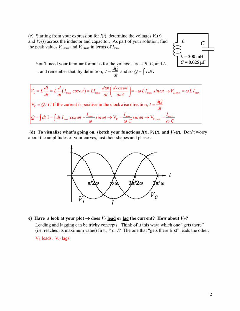
(c) Starting from your expression for I(t), determine the voltages VL(t) and VC(t) across the inductor and capacitor. As part of your solution, find the peak values VL,max and VC,max in terms of Ima
L C
L = 300 mHC = 0.025 PF
L C
L = 300 mHC = 0.025 PF
x.
You’ll need your familiar formulas for the voltage across R, C, and L
... and remember that, by definition, I dQdt
and so Q I dt³ .
� �max max max max
C
max C
V If the current is positive in the clockwise direction,
I = V
L L,max
max max
dI d d t d cos tV L L I cos t LI L I sin t V L Idt dt dt d t
dQQ / C Idt
I IQ dt dt I cos t sin t sin tC
Z ZZ Z ZZ
Z Z ZZ Z
§ · � o ¨ ¸© ¹
o o³ ³
Z
C,maxV
maxI
CZ
(d) To visualize what’s going on, sketch your functions I(t), VL(t), and VC(t). Don’t worry about the amplitudes of your curves, just their shapes and phases.
S/2Z �S�Z�S/2ZS�Zt
VCI VL
S/2Z �S�Z�S/2ZS�Zt
VCI VL
e) Have a look at your plot o does VL lead or lag the current? How about VC? Leading and lagging can be tricky concepts. Think of it this way: which one “gets there” (i.e. reaches its maximum value) first, V or I? The one that “gets there first” leads the other.
VL leads. VC lags.
2

� �� �
0L
Another way of viewing leading and lagging is if and V cos we say V leads I by
We can do this using cos cos sin
= hence V leads I by 90L
C
I cos t t ,
t cos t sin t
V sin t cos t
V sin
Z Z G G
Z G Z G Z
SZ Z
Z
v v �
� �
§ ·v � �¨ ¸�© ¹
v
G
0C = hence V lags I by 90t cos t SZ§ ·�¨ ¸�© ¹
Congratulations! You’ve just derived the master relations between current and voltage for inductors and capacitors in an AC circuit!
Peak Values
VR,max = Imax R VL,max = Imax XL o XL = ZL VC,max = Imax XC o XC = 1/ZC
Relative Phases Across R o V in phase with I Across L o V leads I by 90q Across C o V lags I by 90q
Notice how all the peak-value formulas look like good old “V = IR” o the reactances XL and XC describe the effective resistance of inductors and capacitors in AC circuits.
We now set the circuit into oscillation by “stimulating” it with a brief pulse from some external source of EMF. The result is that the peak voltage across the capacitor is VC,max = 120 V.
(f) What is the peak current Imax?
L = 300 mH C = 0.025 PF
L CVC,max = 120 V
� �� �� �
0
maxC,max max 0 C,max
0
3 6
From part (a) 11 5 krad/sec
From part (c) V V
11 5 10 rad/sec 0 025 10 F 120 V 34 5 mA
.LC
I I CC
. .
Z
ZZ
�
�
o
u u
.
(g) What are the maximum
3

energies UL,max and UC,max stored in the inductor and capacitor respectively?
UL,max = 1/2 L Imax2
= 0.5*(0.3)*(0.03452) = 0.18 mJ
UC,max = 1/2 C (VC,max)2 = 0.5*(0.025u10-6)*(1202) = 0.18 mJ
(h) Determine time-dependent expressions UL(t) and UC(t) for the two stored energies, and add them together to find the total stored energy U(t). Finally, plot your results for all three functions.
Something like this: Utotal(t) = 0.18 mJ, UC is a sin2(Ȧt) function while UL is a cos2(Ȧt) function
S/2Z �S�Z�S/2ZS�Zt
S/2Z �S�Z�S/2ZS�Zt
S/2Z �S�Z�S/2ZS�Zt
(i) How are UL,max, UC,max, and Umax related to each other? Knowing this relation is extremely helpful in solving LC circuit problems!
All are equal:
� �2 22
22
22 2 2
This is no accident but always happens in RC circuits
1 1 1C V2 2 2 2
12 2 21
max maxC ,max C ,max C max
max max maxL,max
I IU C X I CC C
I I LILC UC C/ LC
Z Z§ · § · ¨ ¸ ¨ ¸© ¹ © ¹
§ · ¨ ¸© ¹
1
4
Discussion Question 11C Physics 212 week 11
Phasors
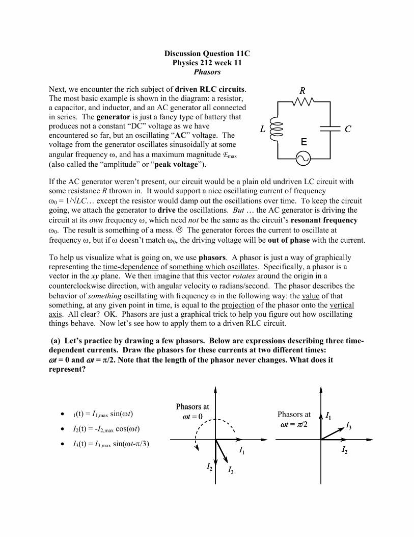
Next, we encounter the rich subject of driven RLC circuits. The most basic example is shown in the diagram: a resistor, a capacitor, and inductor, and an AC generator all connected in series. The generator is just a fancy type of battery that produces not a constant “DC” voltage as we have encountered so far, but an oscillating “AC” voltage. The voltage from the generator oscillates sinusoidally at some angular frequency Z, and has a maximum magnitude Emax (also called the “amplitude” or “peak voltage”).
L C
R
EL C
R
E
If the AC generator weren’t present, our circuit would be a plain old undriven LC circuit with some resistance R thrown in. It would support a nice oscillating current of frequency Z0 = 1/�LC… except the resistor would damp out the oscillations over time. To keep the circuit going, we attach the generator to drive the oscillations. But … the AC generator is driving the circuit at its own frequency Z, which need not be the same as the circuit’s resonant frequency Z0. The result is something of a mess. / The generator forces the current to oscillate at frequency Z, but if Z doesn’t match Z0, the driving voltage will be out of phase with the current.
To help us visualize what is going on, we use phasors. A phasor is just a way of graphically representing the time-dependence of something which oscillates. Specifically, a phasor is a vector in the xy plane. We then imagine that this vector rotates around the origin in a counterclockwise direction, with angular velocity Z radians/second. The phasor describes the behavior of something oscillating with frequency Z in the following way: the value of that something, at any given point in time, is equal to the projection of the phasor onto the vertical axis. All clear? OK. Phasors are just a graphical trick to help you figure out how oscillating things behave. Now let’s see how to apply them to a driven RLC circuit.
(a) Let’s practice by drawing a few phasors. Below are expressions describing three time-dependent currents. Draw the phasors for these currents at two different times: Zt = 0 and Zt = S/2. Note that the length of the phasor never changes. What does it represent?
I3
I1
I2
Phasors atZt = �
I3I1
I2
Phasors atZt = S/2
I3
I1
I2
Phasors atZt = �
I3I1
I2
I1
I2
Phasors atZt = S/2
x 1(t) = I1,max sin(Zt)
x I2(t) = -I2,max cos(Zt)
x I3(t) = I3,max sin(Zt-S/3)
L C
R
E
L = 40 mHC = 2.5 mFR = 15 :
f = 50 HzImax = 0.5 A
L C
R
EL C
R
E
L = 40 mHC = 2.5 mFR = 15 :
f = 50 HzImax = 0.5 A
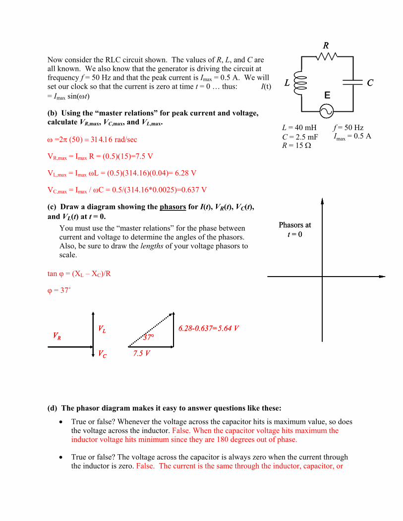
Now consider the RLC circuit shown. The values of R, L, and C are all known. We also know that the generator is driving the circuit at frequency f = 50 Hz and that the peak current is Imax = 0.5 A. We will set our clock so that the current is zero at time t = 0 … thus: I(t) = Imax sin(Zt)
(b) Using the “master relations” for peak current and voltage, calculate VR,max, VC,max, and VL,max.
Z�=2S������ ������� rad/sec
VR,max = Imax R = (0.5)(15)=7.5 V
VL,max = Imax ȦL = (0.5)(314.16)(0.04)= 6.28 V
VC,max = Imax / ȦC = 0.5/(314.16*0.0025)=0.637 V
Phasors att = 0
Phasors att = 0
(c) Draw a diagram showing the phasors for I(t), VR(t), VC(t), and VL(t) at t = 0.
You must use the “master relations” for the phase between current and voltage to determine the angles of the phasors. Also, be sure to draw the lengths of your voltage phasors to scale.
tan ij = (XL – XC)/R
ij = 37˚
VR
VL
VC 7.5 V
6.28-0.637=5.64 V37°VR
VL
VC
VR
VL
VC 7.5 V
6.28-0.637=5.64 V37°
(d) The phasor diagram makes it easy to answer questions like these:
x True or false? Whenever the voltage across the capacitor hits is maximum value, so does the voltage across the inductor. False. When the capacitor voltage hits maximum the inductor voltage hits minimum since they are 180 degrees out of phase.
x True or false? The voltage across the capacitor is always zero when the current through the inductor is zero. False. The current is the same through the inductor, capacitor, or

resistor since all elements are in series. The voltage across the capacitor lags the voltage across the resistor (or the current) by 90 degrees and hence the voltage across the capacitor is either a minimum or maximum when the current is zero.
x True or false? When the magnetic energy stored in the inductor hits is maximum value, so does the electric energy stored in the capacitor. False. The magnetic energy is proportional to the square of current. The electrical energy is proportional to VC . The capacitor voltage lags the current by 90 degrees and hence when the current hits a maximum the voltage across the capacitor is zero.
We now know the voltages across the capacitor, resistor, and inductor. The only thing left to calculate is the EMF E(t) across the generator. From Kirchoff’s Voltage Law, we see immediately that E(t) = VR(t) + VC(t) + VL(t). To perform the sum, we need one more principle: Phasors add like vectors.
(e) What is the voltage E across the generator? Copy your previous phasor diagram, and add a new phasor representing E. What is the length of this phasor? What is the angle I that this phasor makes with respect to the current phasor? VL
E VR
VC
E = 9.39 V, ij = 37˚
6.28-0.637=5.64 V
7.5 V
37°
��=9.39 V 6.28-0.637=5.64 V
7.5 V
37°
��=9.39 V
If you avoided plugging in numbers until the end of your calculation, you just found the last of the “master relations”:
Peak Values Relative Phases
� �22max max L CE I Z Z R X X o � � � �
Across leads by , withtan L C
E V IX X R
II
o
�
These are the current/voltage relationships for the entire RLC circuit, as seen by the generator. The impedance Z is particularly important: it is the effective resistance of the entire circuit.
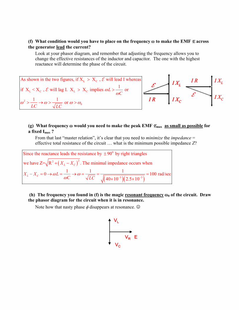
(f) What condition would you have to place on the frequency Z to make the EMF E across the generator lead the current?
Look at your phasor diagram, and remember that adjusting the frequency allows you to change the effective resistances of the inductor and capacitor. The one with the highest reactance will determine the phase of the circuit.
(g) What frequency Z would you need to make the peak EMF Emax as small as possible for a fixed Imax ?
From that last “master relation”, it’s clear that you need to minimize the impedance = effective total resistance of the circuit … what is the minimum possible impedance Z?
(h) The frequency you found in (f) is the magic resonant frequency Z0 of the circuit. Draw the phasor diagram for the circuit when it is in resonance.
Note how that nasty phase I disappears at resonance. -
L C
L C L C
As shown in the two figures, if X X , will lead I wherea1if X < X , will lag I. X X implies or
1 1 or
LC
LC LC
ZZ
Z Z Z Z��
!
! !
! o ! !
�
�
s
I R
I X
I X
L
C
� L
C
I X
I X
I R
�I R
I X
I X
L
C
�
I R
I X
I X
L
C
� L
C
I X
I X
I R
�
� �
� �� �
0
22
3 3
Since the reactance leads the resistance by 90 by right triangles
we have Z= R The minimal impedance occurs when
1 1 10 100 rad/se40 10 2 5 10
L C
L C
X X .
X X LC LC .
Z ZZ � �
r
� �
� o o u u
c
VL
VR EVC
VL
VR EVC
Discussion Question 11D P212, Week 11 RLC Circuits
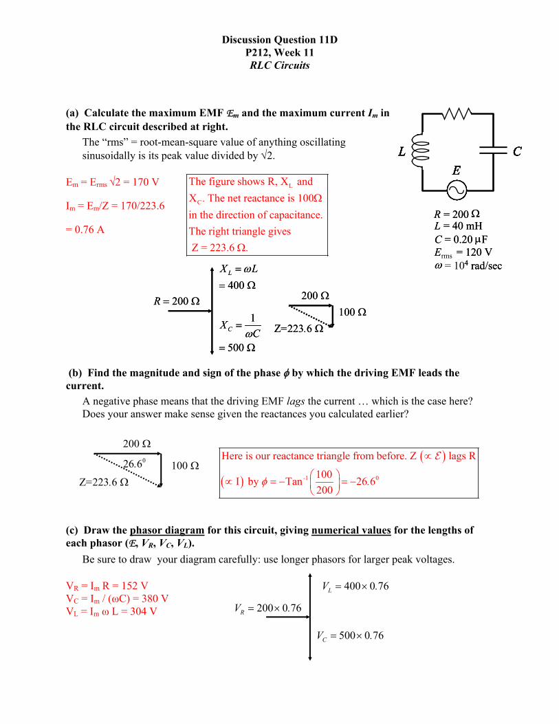
(a) Calculate the maximum EMF Em and the maximum current Im in the RLC circuit described at right.
L CE
L CE
R = 200 :L = 40 mHC = 0.20 PFErms = 120 VZ = 104 rad/sec
R = 200 :L = 40 mHC = 0.20 PFE = 120 VZ 4 rad/sec
L CE
L CE
L CE
L CE
R = 200 :L = 40 mHC = 0.20 PFErms = 120 VZ = 104 rad/sec
R = 200 :L = 40 mHC = 0.20 PFE = 120 VZ 4 rad/sec
R = 200 :L = 40 mHC = 0.20 PFErms = 120 VZ = 104 rad/sec
R = 200 :L = 40 mHC = 0.20 PFE = 120 VZ 4 rad/sec
The “rms” = root-mean-square value of anything oscillating sinusoidally is its peak value divided by �2.
Em = Erms ¥2 = 170 V L
C
The figure shows R, X and X The net reactance is 100in the direction of capacitance. The right triangle gives Z = 223.6
.
.
:
:
Im = Em/Z = 170/223.6
= 0.76 A
400 LX LZ
:
1
500
CX CZ
:
200 R : 200 :100 :
Z=223 6 . :
400 LX LZ
:
1
500
CX CZ
:
200 R : 200 :100 :
Z=223 6 . :
(b) Find the magnitude and sign of the phase I by which the driving EMF leads the current.
A negative phase means that the driving EMF lags the current … which is the case here? Does your answer make sense given the reactances you calculated earlier?
200 :
100 :Z=223 6 . :
026 6. � �
� � -1 0
Here is our reactance triangle from before. Z lags R
100I by Tan 26 6200
.I
v
§ ·v � �¨ ¸© ¹
� �
(c) Draw the phasor diagram for this circuit, giving numerical values for the lengths of each phasor (E, VR, VC, VL).
Be sure to draw your diagram carefully: use longer phasors for larger peak voltages.
400 0 76LV . u
500 0 76CV . u
200 0 76RV . u
VR = Im R = 152 V VC = Im / (ȦC) = 380 V VL = Im Ȧ L = 304 V
L CE
L CE
R = 200 :L = 40 mHC = 0.20 PFErms = 120 VZ = 104 rad/sec
R = 200 :L = 40 mHC = 0.20 PFE = 120 VZ 4 rad/sec
L CE
L CE
L CE
L CE
R = 200 :L = 40 mHC = 0.20 PFErms = 120 VZ = 104 rad/sec
R = 200 :L = 40 mHC = 0.20 PFE = 120 VZ 4 rad/sec
R = 200 :L = 40 mHC = 0.20 PFErms = 120 VZ = 104 rad/sec
R = 200 :L = 40 mHC = 0.20 PFE = 120 VZ 4 rad/sec
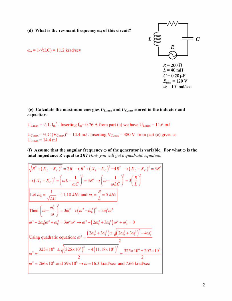
(d) What is the resonant frequency Z0 of this circuit?
Ȧo = 1/¥(LC) = 11.2 krad/sev
(e) Calculate the maximum energies UL,max and UC,max stored in the inductor and capacitor.
UL,max = ½ L Im2 . Inserting Im= 0.76 A from part (a) we have UL,max = 11.6 mJ
UC,max = ½ C (VC,max)2 = 14.4 mJ . Inserting VC,max = 380 V from part (c) gives us UC,max = 14.4 mJ
(f) Assume that the angular frequency Z of the generator is variable. For what Z is the total impedance Z equal to 2R? Hint- you will get a quadratic equation.
� � � � � �
� �
� �
� �
2 22 2 2
2 2 22 2
0 1
22 22 2 2 2 200
4 2 2 4 2 2 4 20 0 0
2 =4 3
1 13 3
1Let =11 18 and 5
Then 3 3
2 3 2 3
L C L C L C
L C
2 2R X X R R X X R X X R
RX X L RC LC L
R. kHz kHzLLC
Z ZZ Z
Z Z
ZZ Z Z Z Z ZZ
Z Z Z Z Z Z Z Z Z Z
� �
�� �
� � o � � o �
§ · § · § ·o � � o � ¨ ¸ ¨ ¸ ¨ ¸© ¹ © ¹ © ¹
§ ·� o � ¨ ¸
© ¹
� � o � �
� � � �
� � � �
2 40
22 20 0 02
2 46 6 3 6 62
2 6 6
0
2 3 2 3 4Using quadratic equation:
2
325 10 325 10 4 11 18 10 325 10 207 102 2
266 10 and 59 10 16 3 krad/sec and 7.66 krad/sec
.
.
Z
Z Z Z Z ZZ
Z
Z Z
� �� �
�
� r � �
u r u � u u r u
u u o
4
2

Discussion Question 11E P212, Week 11
Low-Pass and High-Pass Filters
C
R
EC
R
E
The circuit shown at right has an AC generator of peak EMF Emax and frequency Z connected in series with a resistor R and a capacitor C. Let’s analyze the behavior of this circuit at extreme values of the frequency Z.
Important note: Since there is no inductor present, you may think that we’re back to the material of “RC Circuits” that we studied a month ago. But not so! Those “RC circuits” were connected to DC batteries of constant voltage! This one is being driven by an AC generator, which makes it behave in a totally different way. This is an RLC circuit like any other … the fact that L = 0 just simplifies things a little bit.
(a) Draw a phasor diagram for this circuit, showing the relative phases of the voltages VR, VC, and E.
VR
VC
�
VR
VC
�
(b) Now draw phasor diagrams for the cases when the driving frequency Z is extremely small, and when it is extremely large. In both cases, please answer the following questions: � How does the peak voltage VR,max across the resistor compare with the generator Emax?
(Are they about the same? Or is one very-much smaller than the other?)
� How does the peak voltage VC,max across the capacitor compare with the generator Emax? (Are they about the same? Or is one very-much smaller than the other?)
Super-low frequency case Super-high frequency case VR
� VC
VR
� VC
VC
VR
�VC
VR
�
VR
�
R,max R,max R,max
C,max C,max C,max
For the resistor, which is is true?a) V b) V c)VFor the capacitor, which is is true? a) V b) V c)V
|
|
� �
� �
� � �
� � �
R,maxa) VFor the
R,max R,max
C,max C,max C,max
For the resistor, which is is true? b) V c)V
capacitor, which is is true? a) V b) V c)V
|
|
� �
� �
� � �
� � �

,max max
,max max
R
,max
0
as . From figure Vand
C C
R
C R
V I X RV I R C
V V
oZ
Zof |��� �
,max max
,max max
C
,max ,max
0
as 0. From figure Vand
R
C C
R C
V I R R CV I X
V V
Z o
Zo |��� �
A common application of the circuit we’ve been considering is in audio amplifiers, which process music signals containing many different frequencies. In this application, the generator EMF is produced by something like a CD player, or an old-fashioned record player. This input signal Vin is sent through the resistor and capacitor, and an output signal Vout is produced by connecting an output device (like a speaker) in parallel across either R or C. Here are the two configurations:
RC
Vin VoutRC
Vin Vout
Circuit A
CRVin VoutCRVin Vout
Circuit B
Suppose our music input comes from an old record-player, and is subject to hiss-and-pop scratch noise. These distortions of the music are very short-lived, and so are of very high frequency. Thus, we would like our amplifier to remove signals of very high frequency. This is called a low-pass filter (or “scratch filter”) o when the input signal is of low frequency, the input signal Vin is passed through to Vout without much change … but high-frequency input signals are blocked.
(c) Based on your phasor diagrams, which of the circuits shown would provide a low-pass filter?
The loud speaker in Circuit B records the voltage across the capacitor. In the high Z limit , VC,max approaches zero and hence the high frequency components are blocked. Circuit B is then the low pass filter.
(d) Would the other one provide a high-pass filter (also called a “rumble filter”) which deletes very-low frequency bass noise?
The loud speaker in Circuit A records the voltage across the resistor. In the low Z limit, VR,max o 0 and hence the low frequency components are blocked. Circuit A is thus a high pass filter.
2

(e) Low-pass and high-pass filters can also be constructed using inductors rather than capacitors. Use your expertise with phasor diagrams to determine which of these two circuits would provide a low-pass filter and which would provide a high-pass filter.
Circuit A
Circuit B
3
,max,max ,max
,max
,max ,max
so as
and as 0 . The phases look like this
L LL R
R
L R
V X L V VV R R
V V
Z Zof
Zo
�
�
LRVin Vout
RLVin Vout
LRVin Vout
RLVin VoutRLVin Vout
VLVR
�
VR
� VL
High Z�limit
VR << �VL << �
Low Z�limit
VLVR
�VL
VR
�
VR
� VL
High Z�limit
VR << �VL << �
Low Z�limit
In Circuit A, the loud speaker measures the voltage across R which is very low when Thus Circuit A is a low pass filter.In Circuit B, the loud speaker measures the voltage across L which is very lo
Zof
w when 0. Thus Circuit B is a high pass filter.Zo