l-702/l-702sp lathe & turning center alignment system · lathe and turning center. spindle...
TRANSCRIPT
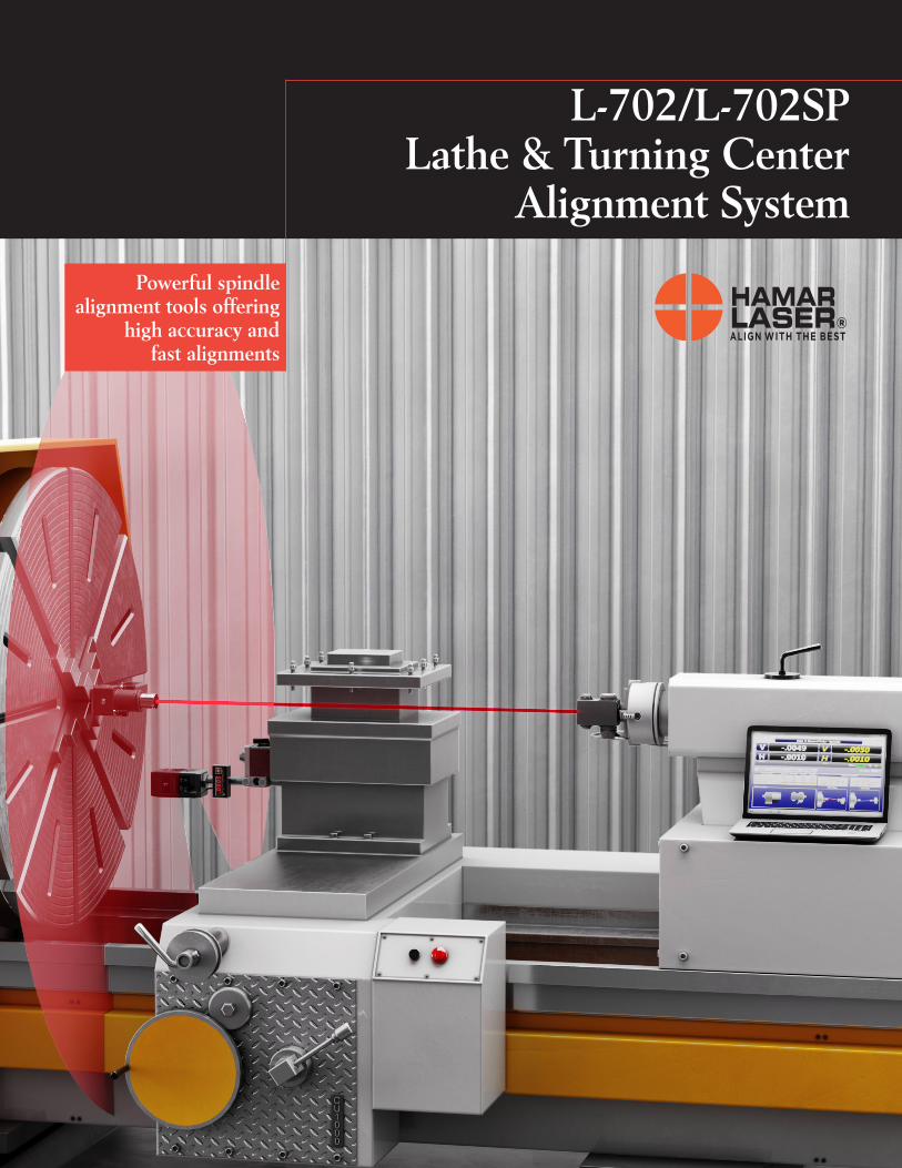
L-702/L-702SP Lathe & Turning Center
Alignment System
Powerful spindle alignment tools offering
high accuracy and fast alignments
Lathe and Turning Center Spindle Alignment
The L-702 & L-702SP 4-Axis Spindle Alignment Systems are powerful alignment tools that offer unparalleled accuracy, easy setup and significant savings in alignment maintenance time. For over 20 years, our spindle alignment lasers have been helping companies reduce tooling costs and scrap rates while increasing their productivity and profitability.
Features• L-702/L-702SP mounts in the spindle to project its
axis of rotation out to 100 feet (30 m).• L-702SP has a perpendicular scan plane to measure
squareness of other axes.• Center resolution: .00001 in. (0.00025 mm)
Angular resolution: .00001 in/ft (0.0008 mm/m).• Live measurement data in 4 axes (vertical and
horizontal angle and center).
• Lathe9 Software corrects mounting errors, calculatesshim values and provides an alignment reportshowing all the alignment parameters of lathealignment.
• Vertical and horizontal controls to precisely adjustthe laser angle to spindle’s rotation axis.
• Laser runs for up to 8 hours on full charge
Typical applications include:• Lathes• Turning Centers• Cylindrical OD/ID Grinders• Multi-Turn Machines• Rotary-Dial Machines• Transfer-Line Machine
The L-702 Spindle Alignment Laser comes in 2 configurations:• L-702 Spindle Laser - is a straight-line laser designed for spindle
alignments in lathes, turning centers, etc.• L-702SP Spindle Laser with Scan Plane – adds a perpendicular scan
plane to the L-702 spindle laser beam for checking cross-slide/turret axissquareness and multi-turn milling axes.
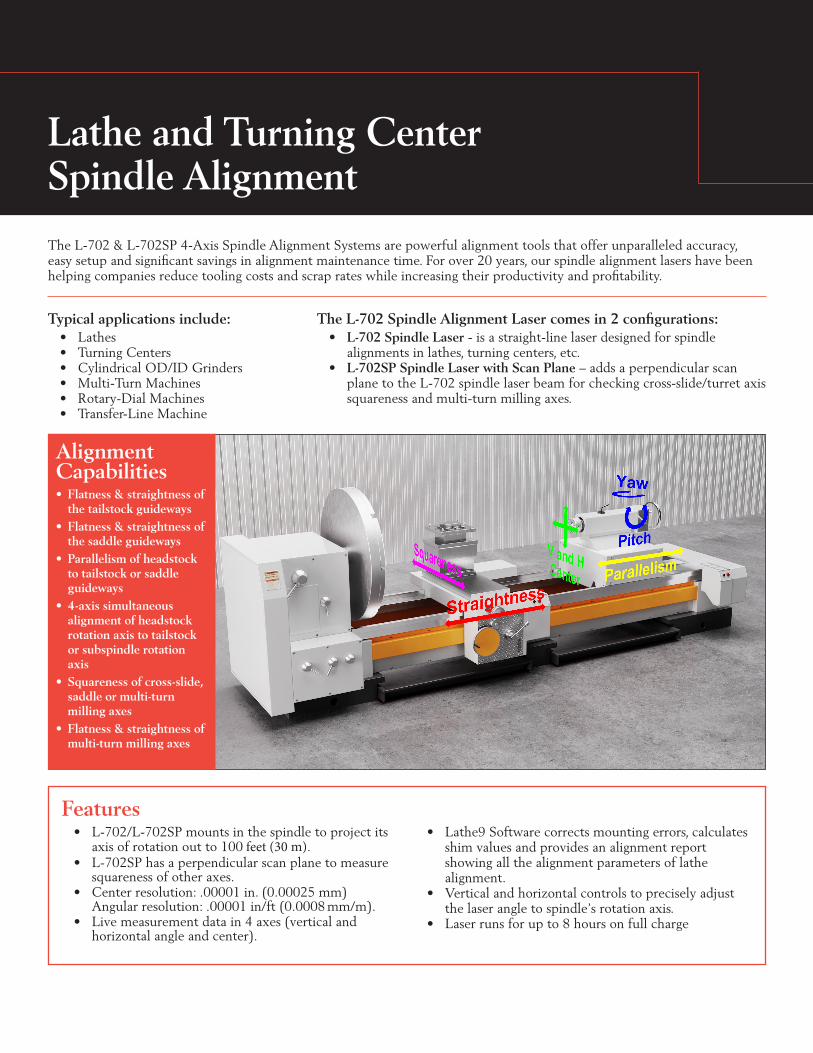
Alignment Capabilities• Flatness & straightness of
the tailstock guideways• Flatness & straightness of
the saddle guideways• Parallelism of headstock
to tailstock or saddleguideways
• 4-axis simultaneousalignment of headstockrotation axis to tailstockor subspindle rotationaxis
• Squareness of cross-slide,saddle or multi-turnmilling axes
• Flatness & straightness ofmulti-turn milling axes

L-702/L-702SP Lathe AlignmentSystem Components
BenefitsHigh Accuracy Improves Part Quality The L-702/L-702SP ultra-high resolution combined with software to correct mounting errors produces a very accurate alignment, less than .0001in. (0.0025 mm), which can dramatically improve machine performance and reduce scrap rates.
Up to 70% Faster Alignments, Reduces Downtime The L-700 significantly speeds machine alignment by providing real-time 4-axis alignment data, so without changing the setup, headstock and tailstock alignment errors can be quickly fixed, while watching Lathe9 software’s 4-axis display update with each adjustment. In most cases, alignment times can be reduced by 60-70%.
Alignment Data in 15 MinutesThe L-702/L-702SP Spindle Alignment System is so easy to set up that a quick alignment check can be done in 15 minutes with the full alignment data in less than 1 hour.
Built-in 6-Step Alignment Software Procedure An easy-to-follow, 6-step alignment procedure is built right into Lathe9, along with popup instructions, that makes a complicated alignment much simplier and easier to learn.
Complicated Lathe Alignment Checks Done with EaseMeasure headstock spindle-axis parallelism with the lathe-bed and saddle guideways, headstock-to-tailstock alignment and spindle-to-subspindle alignment. Upgrade to the L-702SP, which has a perpendicular scan plane, and the cross slide or turret can be measured for squareness! With a measuring range of up to 100 feet, even the longest lathe bed is easy to measure for parallelism to the spindle axis, eliminating the need for expensive and heavy test bars.
L-702 LaserA Class II diode laser with vertical and horizontal angular adjustments to align it to the spindle’s axis of rotation. The operating range is up to 100 feet (30 m).
L-702SP LaserA Class II diode laser with vertical and horizontal angular adjustments to align it to the spindle’s axis of rotation. Also has a laser scan plane that is perpendicular to the laser beam. The operating range is up to 100 feet (30 m).
T-261A 4-Axis Spindle TargetA 4-Axis Spindle Target reads both H & V center and angle (pitch and yaw) simultaneously, allowing a real-time, 4-axis display of alignment.
A-1519-2.4ZB Single Axis ScanTargetA single-axis target that reads the L-702SP scan plane to measure thesquareness of cross-slides, turretsor multi-turn milling axes. Itprovides .00002 in. (0.0005 mm)measurement resolution.
R-358 Computer InterfaceProvides a measurement resolution of .00001 in. (0.00025 mm) for downloading real-time target data into a computer

How It Works: Lathes and Turning Centers
Lathe Alignment Procedure with L-702
One of the most important calibration factors for lathes and turning-type machines is the alignment of spindle axis of rotation (AOR) to the tailstock guideways or the saddle guideways. The other critical calibration factor is the alignment of the spindle’s AOR to the tailstock, sub-spindle, turret or tool holder.
To check the alignment, the L-702/L-702SP is inserted right into the spindle chuck and aligned to the spindle’s AOR, using the T-261 4-Axis Target mounted in the tailstock or T-230 TargetStand. The L-702 laser projects the spindle’s AOR out to 100feet (30 m) and becomes the reference from which the guideways,toolholder and tailstock can be measured and aligned. Even thelargest lathes can be quickly and easily aligned without changingsetups, replacing heavy, cumbersome alignment test bars.
Step 1 - Machine SetupInsert L-702 into headstock chuck, T-261 into tailstock and connect to R-358. Open Lathe9, enter projectname, number of points, dimensionsand tolerances.
Step 3 - Live Move ScreenTo align the headstock to the bed, Lathe9 calculates the shim values and displays a live move screen, which updates the spindle’s AOR vertical and horizontal parallelism values as the shims are being added.
Step 3 - Record Lathe Bed StraightnessInsert T-261 into tailstock or toolholder and bring it close to the laser in the headstock. Hit record. Move to next point and hit record again and repeat until all the points have been recorded.
Step 5 - Tailstock/Subspindle Record ScreenRecord 3 data points by rotating the spindle/laser and target in the tailstock and Lathe9 will calculate the alignment results of the tailstock or subspindle to the headstock spindle’s AOR.
Step 2 - Qualify LaserRecord a data point with the spindle at 6:00. Rotate spindle/L-702 180 degrees to 12:00 and hit Record again. Display offsets are created so you can adjust the V & H angles to zero, aligning the laser to the AOR.
Step 4 - Results and Guide-Rail Straightness GraphDisplays a summary of the alignment results and a graph of the guide-rail straightness with several choices to view the graph. If in tolerance, then proceed to Step 5 to check Headstock/Tailstock alignment.
Step 3 - Alignment ResultsThe vertical and horizontal straightness, spindle AOR parallelism to the main and/or saddle bed ways are displayed and the tolerances are applied. If out of tolerance, the bedway straightness must be fixed and the headstock aligned to the bed before proceeding.
Step 6 - Tailstock/Subspindle Live Move ScreenA live display for each of the 4 alignment values of the tailstock or subspindle relative to the headstock spindle AOR with shim and spacer calculations to fix the alignment. The alignment values update as shims and spacers are inserted or removed.

Other Applications
Machining Center Geometry With the L-702LB Leveling Base accessory the L-702SP can be used with the A-1519-2.4ZB Wireless Scan Target to level machine beds. With the T-261 4-Axis Target and the T-230 Target Stand, the L-702SP can also be used for:
• Flatness & straightness of X, Y & Z axes• Squareness between the axes• Spindle tramming
Large Rotary-Dial MachinesThe critical alignment of a rotary-dial machine is the axis of rotation of the spindle to the sub-spindle or part holder.
Similar to transfer line alignment setup, a .4995 (12.687 mm) stud on the laser is inserted into the spindle chuck and the laser beam is aligned to the axis of rotation of the spindle. The spindle axis of rotation can then be projected out to the part holder, where the 4-axis target measures misalignment of the spindle head for straightness, squareness to the part holder and parallelism to the ways.
Multi-Turn MachinesThe L-702SP Spindle Laser with scan plane gives the ability to check other axes on multi-turn machines. The perpendicular scan plane combined with the A-1519-2.4ZB Single Axis Target makes the task very simple. After setting up the L-702SP to the spindle’s rotation axis, the A-1519-2.4ZB is attached to the X axis milling head and zeroed. The X axis is traversed and any deviation is a measure of the straightness of the axis and squareness error to the main spindle axis. The milling head can then be traversed along the Y axis to measure it’s straightness and squareness or the flatness of the X-Y plane can be measured.
The T-261 can also be used to measure the parallelism of the multi-turn axes to the main spindle axis by attaching it to the milling head and traversing it along the Z axis.
Automaker Saves MillionsA “big three” auto manufacturer’s misaligned transfer lines were breaking one tool every 50 parts. After using Hamar’s L-700 Spindle Alignment System the breakage rate was reduced to one in every 6,000 parts — an 11,900% improvement!The company was ultimately able to save $1.5 million annually in reduced tooling costs and increased production by 20engines per day on just one line alone!
Specifications
T-261 4-Axis Spindle Target
L-702/L-702SPLathe & Turning Center
Alignment System
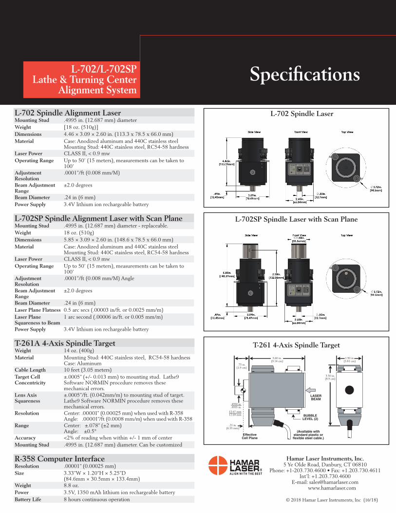
L-702 Spindle Alignment LaserMounting Stud .4995 in. (12.687 mm) diameter Weight [18 oz. (510g)] Dimensions 4.46 × 3.09 × 2.60 in. (113.3 x 78.5 x 66.0 mm) Material Case: Anodized aluminum and 440C stainless steel
Mounting Stud: 440C stainless steel, RC54-58 hardnessLaser Power CLASS II, < 0.9 mwOperating Range Up to 50’ (15 meters), measurements can be taken to
100’Adjustment Resolution
.0001”/ft (0.008 mm/M)
Beam Adjustment Range
±2.0 degrees
Beam Diameter .24 in (6 mm)Power Supply 3.4V lithium ion rechargeable battery
L-702SP Spindle Alignment Laser with Scan PlaneMounting Stud .4995 in. (12.687 mm) diameter - replaceable. Weight 18 oz. (510g) Dimensions 5.85 × 3.09 × 2.60 in. (148.6 x 78.5 x 66.0 mm)Material Case: Anodized aluminum and 440C stainless steel
Mounting Stud: 440C stainless steel, RC54-58 hardnessLaser Power CLASS II, < 0.9 mwOperating Range Up to 50’ (15 meters), measurements can be taken to
100’Adjustment Resolution
.0001”/ft (0.008 mm/M) Angle
Beam Adjustment Range
±2.0 degrees
Beam Diameter .24 in (6 mm)Laser Plane Flatness 0.5 arc secs (.00003 in/ft. or 0.0025 mm/m)Laser Plane Squareness to Beam
1 arc second (.00006 in/ft. or 0.005 mm/m)
Power Supply 3.4V lithium ion rechargeable battery
T-261A 4-Axis Spindle TargetWeight 14 oz. (400g)Material Mounting Stud: 440C stainless steel, RC54-58 hardness
Case: AluminumCable Length 10 feet (3.05 meters)Target Cell Concentricity
±.0005” (+/- 0.013 mm) to mounting stud. Lathe9 Software NORMIN procedure removes these mechanical errors.
Lens Axis Squareness
±.0005”/ft. (0.042mm/m) to mounting stud of target. Lathe9 Software NORMIN procedure removes these mechanical errors.
Resolution Center: .00001" (0.00025 mm) when used with R-358 Angle: .00001”/ft (0.0008 mm/m) when used with R-358
Range Center: ±.078” (±2 mm) Angle: ±0.5°
Accuracy <2% of reading when within +/- 1 mm of centerMounting Stud .4995 in. (12.687 mm) diameter. Can be customized
R-358 Computer InterfaceResolution .00001” (0.00025 mm)Size 3.33”W × 1.20”H × 5.25”D
(84.6mm × 30.5mm × 133.4mm)Weight 8.8 oz.Power 3.5V, 1350 mAh lithium ion rechargeable batteryBattery Life 8 hours continuous operation
Hamar Laser Instruments, Inc.5 Ye Olde Road, Danbury, CT 06810
Phone: +1-203.730.4600 • Fax: +1.203.730.4611 Int’l: +1.203.730.4600
E-mail: [email protected]
© 2018 Hamar Laser Instruments, Inc (10/18)
L-702 Spindle Laser
L-702SP Spindle Laser with Scan Plane