%.kyravknic bolid oxycian storage and … · automatic mailini,- lists should submit the...
TRANSCRIPT
AMRL-TR-68-105
%.KYrAvkNIC bOLID OXYCiAN STORAGEAND SUBLIMATION INVESTIGATION
JOHN E. AHIERN
TRUMAN W. LAWSON, JR.
.'lerojet G~ixeal Lorpmuiaon
DF'CaS-M]EI1 1968
1lhis document hm be-,n approved for publicr- ..ase &.4 ale;, -s tuistT.ýution is unlimited. *
AERIOSPACE MIEDICAL RESEARCH LAB1IO.ATORIESIIAt )SPACTE W7i)IC! 1, .A VI-010N
AIR FORCE SYSTEMS COMMANDwitiIGHTr-PkyrERSON A;R FOL-ICE BASE, OHJ')
NOTICER
When US Government drawings, specifications, or other data are used for any purpose other thana definitely related Government procurement operation, the Government thereby incurs no responeaibility nor any obligation whatsoever, and the fact that the Government may have formulated, fur-nished, or in any way supplied the said drawings, sy, .Zifications, or other data, is not to be regardedby implication or otherwise, as in any manner licinsing the holder or any other per-u ')9 corpora-tion, or conveying any rights or permission to manufacture, use, or sell any pAteVted inventionthat t.Ay in any way be related thereto.
Federal Government agencies and their contractors registered with Defeore Docup-,"tation Center(DDC) should direct requests for copies of this report to:
DDCCameron StationAlexandria, Virginia 22314
Non-DDC users may purchase copies of this report frorn:
Chief, Storage and Dissemination SectionClearinghouse for Federal Scientific & Technical Information (CF )Sills Building5285 Port Royal RoadSpringfield, Virginia 22151
Organizations a:,. individuals receiving reporta via the Aerobpeý_e Medical Research Laboratories'automatic mailini,- lists should submit the addressograph plate stamp on the report envelope orfderto the code number wher corresponding about .-hange of address or carcellatmn.
Do not return this copy. ReVtin or destroy.
jKi 7
\ A~ .~ C:s y, 1

AMRL-TR-68-105
CRYOGENIC SOLID OXYGEN STORAGE
LAND SUBLIMATION INVESTIGATION
JOHN E. AIHERN
TRUMAN W. LAWSON, JR.
"This do(tmwrit has been approwed for publicrelease and saile its d(stribulion is unlhmited.

FOREWORD
This program was conducted by Aerojet-General Corporation, Azusa,California, during tlPe period from 1 July 1967 through 31 March 1968,under Contract F33615--67-C-1849 and in support of Project 6373, "Equip-ment for Life Support," Task 637302, "Respiratory Support Equipnent."The program was sponsored by the Aerospace Medical Research Laboratoriesand monitored by Mr. Konrad Weiswurm of the Biotechnology Branch, LifeSupport Divisioin., Biomedical Laboratory, Aerospace Medical ResearchLaboratories, Wright-Patterson Air Force Base, Ohio. This report hasbeen catalogued as Report No. 3545 by Aerojet.
The Principal Investigator at Aerojet-General Corporation, Azusa,California, was Mr. Norman Plaks, who was supported in this program byT. W. Lawson in the analytical phase, U. E. Gross, and E. Ogg in theexperimental phase, and J. E. Ahern. The program was conducted underthe management supervision of Mr. Lloyd Candell, Head of the Thermal andEnvironmental Systems Design Group.
This technical report has ijeen reviewed and is approved.
C. H. KRATOCHVIL, Colonel, USAF, MCCommanderAerospace Medical Research Laboratories

SUMMARY
The objectives of this program were (1) to determine analytically theadvantages of using solid oxygen for long-term storage compared to sub-critical liquid and supercritical oxygen for space systems, and (2) todetermine the feasibility of transporting oxygen from the solid state to acondition suitable for breathing.
The analysis was made for two crnditions of oxygen storage - with con-tinuous use by crew members, and under conditions where oxygez, is not beingcontinuoasly used during the storage period. Practical storage vessel designswere selected for the study having supports to with3tand two different G loads.Both multilayer and multiple-shield insulations were used in the study.Equations were developed to determine the initial storage system weight andthe oxygen supply duration as a function of the type of oxygen storage -solid, saturated liquid, and supprcritical fluid. In the caqse of cointinuoususe of the oxygen for space cabin -upply, the number of crew members andcabin leakage were additional independent parameters. The equations wereprogrammed for the IBM 360 and cases were run over a range Af potential spacemissions conditions.
For the case of continuous consumption by crew members, the resultsindicated that solid oxygen had a small performance advantage over thepresently used subcritical oxygen supply system. This advantage would benullified by the need for additional equipment to transport the solid oxygento a breathable state. In this application, the need to draw off oxygen at agiven rate for crew consumption nullified the major advantage of solid oxygen -
the greater heat absorbing capability of solid oxygen over the liquid andsupercritical state.
When the oxygen was not being continuously used to supply a space cabinatmosphere for cr-w members, storage of oxygen in the solid state was foundto be significantly better from a iuration standpoint than storing the oxygenas a saturated liqiid for a -"nercritical fluid. The gain is significantenough to seriously consider solid oxygen in place of subcritical or super-critical oxygen for long-term storage under these conditions. Supercriticaloxygen was shown to be poor for long-term storage due to the lower specificheat of the fluid in the supercritical condition. The better performance ofsolid oxygen, more than twice the storage life in this case, is due to thefact that advantage is taken of the heat of fusion, heats of transition, andthe additional sensible heat in solid oxygen to extend the 2torage life.
iii

Experimental studl's were conducted on transporting oxygen from the vacuumstorage condition to a condition suitable for breathing. Oxygen was solidifiedfor these experiments by cooling with solid nitrogen under vacuum conditions.Two transport methods .rere evaluated. One method was to adsorb the vaporsubliming from the solid oxygen on molecular-sieve cryosorption pumps cooledto liquid nitrogen temperature. After the pump is saturated with oxygen vapor,it is isolated frcm the vacuum storage vessel and heated to de-adsorb theoxygen into the space cabin atmosphere. The experiments showed that thismethod is feasible. However, low vapor flow conductance and slow cryosorptionpump cooldown rates were encountered in the experimental work. Practicn' appli-cation of this transport method to space systems will require system designsthat avoid these problems.
The other transport method which was experimentally evaluated was tophysically move a solid piece of oxygen from the vacuum storage vessel to thespace cabin atmosphere. An airlock system was used to maintain a vacuum inthe storage vessel during the transfer. During transfer, one valve is openedbetween the airlock chamber and the storage vessel. The solid oxygen blockis mechanically moved inro the airlock chamber. When the valve is closedbetween the airlock chamber and the storage vessel, and the valve openedbetween the airlock chamber and the cabin atmosphere, the solid oxygen meltsand vaporizes into the cabin atmosphere. Initial transfer of the solid oxygenwas attempted by using a magnet since oxygen possesses paramagnetic properties.Although the oxygen could be picked up and moved, these preliminary resultswere inconclusive because of secondary adhesion effects due to the oxygenfreezing to the magnet. The solid oxygen block could be readily picked unwith a nook or with a magnet if a wire was frozen into the oxygen block.There appeared to be no problem in adapting this transport method to a spacesystem.
Storage of oxygen in the solid form was shown to have significant advan-tages over the liquid or supercritical fluid when the oxygen was consumed onlyIntermittently. Transport of the solid oxygen in blocks through an airlockvalve was also found to be feasible. These methods coid be used in a practicaloxygen storage system as an emergency or reserve supply or for extra-vehicularac ivities.
tv

TABLE OF CONTENTS
SECTION I
INTRODUCTION ..................... ............................ . I
PROGRAM OBJECTIVES ..................... ..................... 1
Analytical Study. .................... 1
Experimental Study ............. .................. . i.. 1
BACKGROUND TECHNOLOGY .................. ..................... 2
SECTION II
PROGRAM PLAN ................... ............................... 3
EXPERIMENTAL PLAN .............. ....................... . .. 3
ANALYTICAL PLAN ........................ ...................... 3
GENERAL OXYGEN PROPERTIES ................ ................... 5
SECTION III
EXPERIMENTAl 3TUDY ....................... .......................... 8
OXYGEN TRANSPORT BY THE ADSORPTION MFTHOD ........ ........... 8
Solid Oxygen Sublimation Laboratory Tests ...... ........ 8
Test Apparatus ............... .................. 8
Test Operations ................ .................. 8
Procedure ................ .................. 8
Shakedown Operation .... ............. ... 12
Test Runs .............. .................. 16
Test Results ........... ................... .. 18
Cryosoxption Finp Adsorption 1,aboritory Tetts ...... 18
*'e,- t App;-rýLtus ........... ................... ..
S. .on . . . . . . . . . . . . . .. . . .. 1,3.es .••' . . . . . . . . . . . . . . . . .. . . 20

Table of Contents (Continued)
Page
Evaluation and Application of Results ..... ........ .... 22
OXYGEN TRANSPORT BY MECHANICAL MANIPULATION ..... .......... ... 25
Laboratory Tests .................... 25
Preliminary Experiment ............ ............... 28
Test Operations ............. ................. ... 34
Discussion of Test Results ................ ........ 39
Evaluation and Application of Results ... ........... ... 39
DISCUSSION OF EXPERIMENTAL RESULTS ........ ............... ... 39
SECTION IV
ANALYTICAL STUDY ................... ........................... ... 41
OBJECTIVE ................. ............. .......... 41
BACKGROUND TECHNICAL AREA ............. .................... ... 42
STORAGE SYSTEM DESIGN FOR THE ANALYTICAL STUDY ... ......... ... 45
STORAGE OF OXYGEN WITH NO USAGE ......... ................. ... 49
Analytical Procedures ........... ................... ... 49
Results of the Analyses ....... ............... ...... 49
Discussion of Results ........... ................... ... 50
STORAGE OF OXYGEN WITH US,'GE..E .............. .................. 64
Analytical Procedure ................... 64
Results of the Analyses ........... .................. 6.
Discussion of Results ......... ................... ...
SOLID OXYG1EN' ST(PAGE AND S71PLY SY ... . ... ... . ..... .. 7Q
:,stems for S-ice CU in Cxy.ren utly.. .
ystems ý'or Long-'@r%: Stortige ......... ............... I
S:'tenmq for Ext -- VehP-ul~r Aciivl l. ..
S vr 1,"em
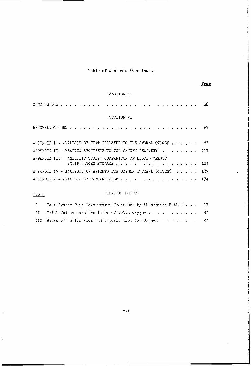
Table of Contents (Continued)
SECTION V
CONCLUSIONS . . . . . . . . . . . . . . . . . . . . . . . . . . . . . . 86
SECTION VI
RECOMMENDATIONS .................................................... 87
AIPENDIX I - ANALYSIS OF HEAT TRANSFER TO THE STORED OXYGEN ........ ... 88
APPENDIX II - HEATIN'r, REQUIgEMENTS FOR OXYGEN DELIVERY ...... ........ 117
APPENDIX III- ANALYTIC STUDY, COMiARISON OF LIQUID VERSUSSOLID OXYGEN STORAGE ........... .................. ... 124
APPENDIX IV - ANALYSIS OF WEIGHTS FOR OXYGEN STORAGE SYSTEMS . . . . . 137
APPENDI( V - ANALYSIS OF OXYGEN USAGE. ........ ................. ... 154
Table LIST OF TABLE
I Tez;t System Rlmp Down Oxygen Transport by Absorption Method . . . 17
II Molal Volumes and Densities o! Solid Oxygen .... ........... ... 43
III Heats of S'iblimition ind Vaporizatic-. for Oxygen ........ 1
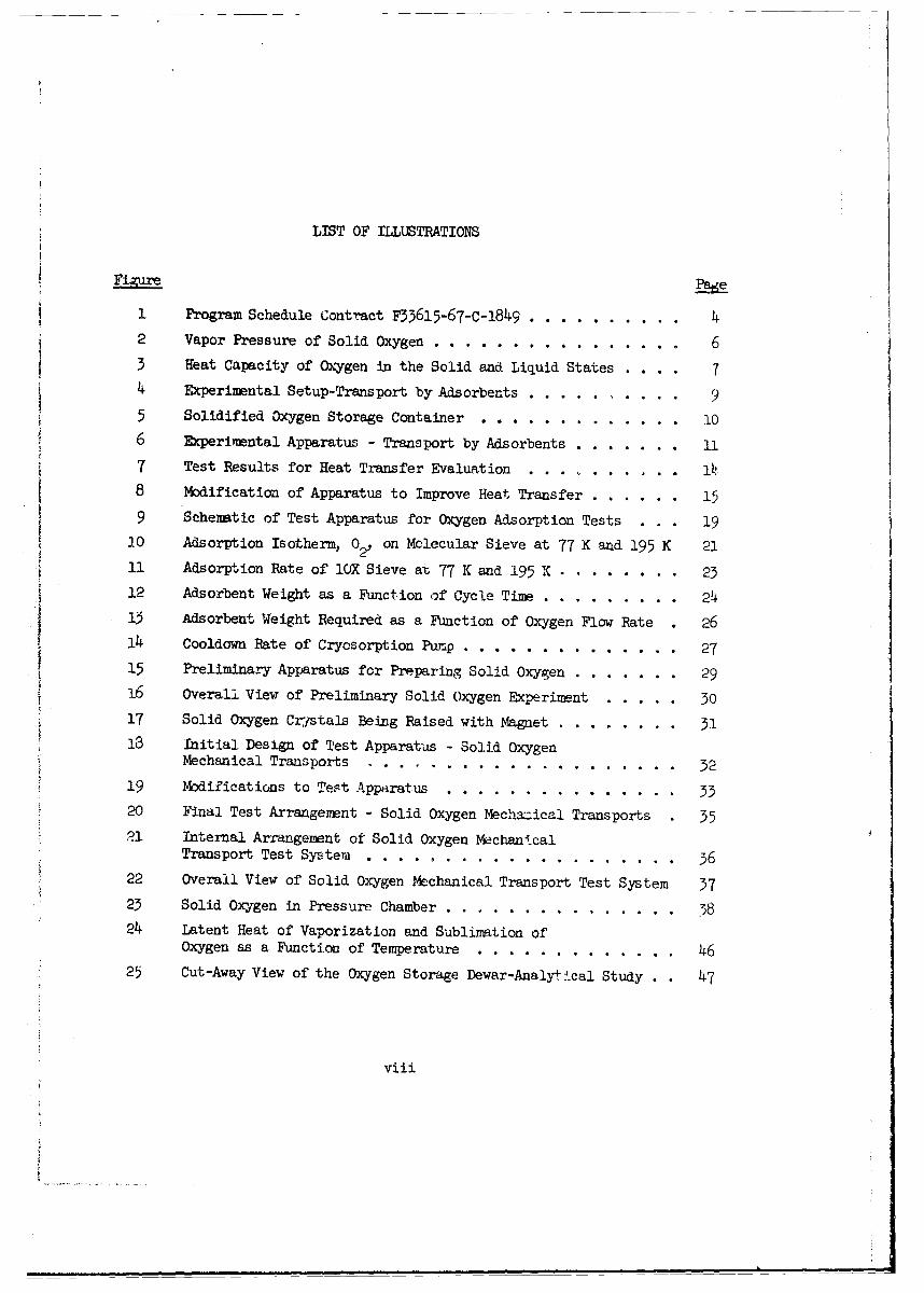
LIST OF ILLUSTRATIONS
FigureP
1 Program Schedule Contract F33615-67-C-1849 .......... 42 Vapor Pressure of Solid Oxygen ........... ................ 63 Heat Capacity of Oxygen in the Solid and Liquid States . . .. 74 Fxperimental Setup-Transport by Adsorbents ...... ......... 9
5 Solidified Oxygen Storage Container ..... ............. .... O6 Experimental Apparatus - Transport by Adsorbents .... ....... 11
7 Test Results for Heat Transfer Evaluation ........... i.l
8 Modification of Apparatus to Improve Heat Transfer ...... 15
9 Schematic of Test Apparatus for Oxygen Adsorption Tests . . . 19
20 Adsorption Isotherm, 02, on Molecular Sieve at 77 K and 195 K 21
11 Adsorption Rate of lOX Sieve at 77 K and 195 X . ..... ...... 2312 Adsorbent Weight as a Function of Cycle Time ..... ......... 24
13 Adsorbent Weight Required as a Function of Oxygen Flow Rate 26
14 Cooldown Rate of Cryosorption Pump .... ............. .... 2715 Preliminary Apparatus for Preparing Solid Oxygen ......... ... 29
16 Overall View of Preliminary Solid Oxygen Experiment ... ..... 30
17 Solid Oxygen Crystals Being Raised with Magnet ..... ........ 31
13 Initial Design of Test Apparatus - Solid OxygenMechanical Transports ..... ........... ................... 32
19 Modifications to Test Apparatus ..... ..... ............... 3320 Final Test Arrangement - Solid Oxygen Mechazical Transports 35
21 Internal Arrangement of Solid Oxygen MechanicalTransport Test System.. ........ .................... 36
S22 Overall View of Solid Oxygen Mechanical Transport Test System 37
23 Solid Oxygen in Pressure Chamber ......... ............... 5824 Latent Heat of Vaporization and Sublimation of
Oxygen as a Function of Temperature ..... ............. ... 4625 Cut-Away View of the Oxygen Storage Dewar-Analyt cal Study . . 47
viii

List of Illustrations (Continued)
Figure
26 Extended Storage Time of Liquid Oxygen by Subliming andMelting Solid Oxygen as a Function of Inner ContainerRadius (Solid Oxygen Storage 54.36 K, Flexible Multi-layer Insulation) ........ ... ...................... ... 51
27 Extended Storage Time of Liquid Oxygen by Subliming andMelting Solid Oxygen as a Function of Inner Container Radius(Solid Oxygen Storage at 54.36 K, Rigid Shield Insulation . . 52
28 Extended Storage Time of Liquid Oxygen by Subliming andMelting Solid Oxygen as a Function of Inner Container Radius(Solid Oxygen Storage at 43.8 K, Flexible Multilayer Insulation) 53
29 Extended Storage Time of Liquid Oxygen by Subliming andMelting Solid Oxygen as a Function of Inner Container Radius(Solid Oxygen Storage at 43.8 K, Rigid Shield Insulation) . . . 54
30 Comparison of Solid as a Function of Liquid OxygenStorage Times, Flexible Multilayer Insulation R1 = 30 CM,TIS = 1.O CM, 86.6 G ............... .... 55
31 Comparison of Solid az a Function of Liquid Oxygen Six't•&eTimes, Flexible Multilayer Insulation R1 = 30 CM, TrS = 1.0 CM,l0.O G ..... ......... ....... ........................... 56
32 Comparison of Solid as a Function of Liquid Oxygen StorageTimes, Flexible Mulrilayer Insulation R. = 30 CM,TINS = 1. -ocm, 86.6 G . ......... 5T l.C,8.6............................... 57
33 Comparison of Solid as a Function of Liquid Oxygen StorageTimes, Flexible Multilayer Insulation R. = 70 CM, TINS = 1.0 CM,86.6 G . . . . . . . . . . . . . . . .. 58
3)4 Comparison of Solid as a Function of Liquid Oxygen StorageTimes, Rigid Shield Insulation R. = 39 CM, N = 0, 86.6 G ••59
35 Comparison of Solid as a Function of Liquid Oxygen StorageTimes, Rigid Shield Insulation R. = 30 XM, N = 0, 10 G . . 60
36 Comparison of Solid as a Function of Liquid Oxygen StorageTimes, Rigid Shield Insulation R - 30 CM, N = 2, 86.6C• 61
37 Comparison of Solid as a Function of Liquid Oxygen StorageTimes, Rigid Shield Insulation R = 30 CM, N = 2, 10 G . . . 62
38 Required Initial 0xyt-z: Weight as a Function of MissionLength and Number of Men and Heat Transfer Into theContainer for Solid Oxygen Storage - 86.6 G ............ ... 66
ix

List of Illustrations (Continued)
_ Page
39 Required Initial Oxygen Weight as a Function of MissionLength and Number of Men and Heat Transfer into theContainer for Liquid Oxygen Storage - 86.6 G ....... ... 67
4o Required Initial Oxygen Weight as a Function of MissionLength and Number of Men and Heat Transfer Into theContainur for Supercritical Oxygen Storage - 86.6 G . . 68
41 Required Initial Oxygen Weight as a Function of MissionLength and Nwmber of Men and Heat Transfer Into theContainer for Solid Oxygen Storage - 10.0 G .. ....... .. 69
42 Required Initial Oxygen Weight as a Function of MissionLength and Number of Men and Heat Transfer Into theContainer for Liquid Oxygen Storage - 10.0 G ....... ... 70
Required Initial Oxygen Weight as a Function of MissionLength and Number of Men and Heat Transfer Into theContainer for Supercritical Oxygen Storage - 10.0 G . . . 71
44 Mission Length Without Dumping Oxygen as a Function ofInsulation Thickness (One Man Usage) ............ 72
45 Mission Length Without Dumping Oxygen as a Function ofInsulation Thickness (Three Men Usage) .... ........... 73
46 Mission Length Without Dumping Oxygen as a Function ofInsulation Thickness (Seven Men Usage) ..... ........... 74
47 Total Weight as a Function of Mission Length and Numberof Men (Insulation Thickness = 0.5 Centimeters,Flexible Multilayer Type) ...... .................. .... 75
48 Total Weight as a Function of Mission Length and Numberof Men (Tnjulation Thickness = 5.0 Centimeters,Flexible Malt-±Layer Type) ...... ................. ..... 76
49 Three Cryosorption Pump Transfer System ...... .......... 81
50 Maximum Rate of Sublimation of Oxygen ... ........... ... 82
51 Flow Conductance of Subliming Oxygen Vapor Zero FlowLength Assumed (Orifice) ...... ....... ................. 83
52 Cross-Section View of Oxygen Container IllustratingInsulation Shielding Geometry ...... .............. .... 92
53 Flexible Multilayer Thermal Conduction Parameter(T,298) (298-T)........... ......................... 95
x

List of Illustrations (Continued)
Figure Page
54 Hemispherical and Normal Emittance and Absorptance of Gold . 94
55 Thermal Conductivity of Titanium Alloy vs Temperature ... 105
56 Total Heat Transfer Through Insulation and Supports as aFunction on Internal Container Radius - Solid Oxygen Storage . 111
57 Total Heat Transfer Through Insulation and Supports vsInternal Container Radius - Liquid Oxygen Storage . . . . . . 112
58 Total Heat Transfer Through Insulation and Supports vsInternal Container Radius - Supercritical Cxygen Storage,Initial Storage ............ ....................... .. 113
59 Total Heat Transfer Through Insulation and Supports vsInternal Container Radius - Supercritical Oxygen Storage,at Minimum Required Heating ....... ..... ................. 114
60 Specific Heat Input for Constant Pressure Delivery -Supercritical Oxygen Storage ........ ... ................ 115
61 Fluid Temperature for Constant Pressure Delivery -
Supercritical Oxygen Storage . . . .............. 1662 Procedure I: Oxygen Initially Stored as a Solid
at the Triple Point .............. ..................... 125
63 Procedures II and III: Oxygen Initially Stored as aSoid at 43.79 K (Phase II), and 12 K (Phase III,Respectively ............. ........................ .. 126
64 Oxygen Container ............ .. . .. *.......... 138
65 Inner Container Radius vs. Stored Oxygen Weight .... ....... 141
66 Oxygen Usage Rate as a Function of Number of Men,Leakage Rate and Air-Lock Usage Factor - 150 Tor-r. ......... 157
67 Oxygen Usage Rate as a Function of Number cf ,ienLeakage Rate and Air-Lock Uszge Factor - 250 Torr ........... 158
xi

SECTION I
INTRODUCTION
The oxygen c~orage and supply system is a critical component of a mannedspace vehicle. The larger number of crew members now being considered foradvance space vehicles will impose severe requirements on the environmentalcontrol system from the standpoint of reliable long-term storage of oxygen.Oxynen is conventionally stored as a liquid in either the subcritical or super-critical conditions. However, volume storage capacity of oxygen can be reducedif the oxygen is stored as a solid. Certain -enefits a~pear to exist for solidoxygen in terms of transporting oxygen under zero-G condition and for long-termdead storage of oxygen.
Under the sponsorship of the Aerospace Medical Research Laboratories,Aerojet-General has performed a lO-month pzogram encomparsing both analyticaland experimental tasks to evalu te the use of solid oxygen for the environmentoxygen supply of a manned space vehicle. This report represents the culminationof the propram effort and contains the results of the analytical and experi-mental studies. The informntion provided by this stildy will allow the selectionof practical approaches for further study with respect to thei.r application toexisting and future system requirements.
PROGRAM! OBJZCTIVES
Akalytical Study
The basic objective of the analytical tudy was to evaluate thestorage capability of solid oxygen in comparison with storave of oxygen in thesubcritical and supercritical condition. The comparison was to be made usingrealistic cryogenic storage vessels h'-ving a range of insul-tion characteristicsand designed to survive high launch G-loads. Two storage conditions -ire ofinterest for solid oxygen: (1) comparatively lonq-term storage without usingthe oxygen followed by a period of usage and (2) short-term stora'-e where theoxygen will be used for crew breathinr? as soon as the vehicle is in orbit. Acomparison of solid oxygen with subcritical and supercritical oxyRer for thesetwo conditions is of interest. The evalu-tion of these analytical comparisonswill indicate the practical aeplications of solil oxygen as well as the potentialgain in performance by usinf' solid oxygen.
zxpcrimenta] itudy
The basic objective of the exrerimental rro-ran• was to 'emonstrltethe felsibility of transportiam the oxvyre- from tee snli'" .storae conditionsto the conditions svitable for use by crew members, i.e., an oxygen Pressure ofabout 150 tirr at ambilnt temperature. Two methods appeared tc he of interest;one method involves the adsorption and desorption of the oxy-en vapor on anadsorbent, and the second method involves the mechanical movement rf' the solidoxygen through an airlock between the two pressure and te-perature conditions.The tests were directed toward estabiishing the feasibility of these methodsand obtaining data for a reliminnry evw•ut:tjon of' the -ractic;-lity o(f sij rthese ,ppro.-ches in an operatin;, system.
1

BACKGROUND NVCHNOLOGY
Solid cryogens have found many uses in advanced technology areas, primarilyfor space and airborne applications. Many of these applications involve the useof the cryogen for cooling (Plaks, 1966; Gross et al, 1962; and Gross et al,1964). Slush or solid hydrogen have also been considered for improving propel-lant storage in hydrogen-fueled vehicles. The major factor involved in theconsideration of the solid phase is the fact that many problems associated withstorage of the liquid or gas can be avoided. These include liquid sloshingdurina vehicle maneuver, zero-G two-phase supply problems with subcritical liquid,and high pressure tankage requirements for the supercritical liquid and gasstorage.
Solid storage of oxygen has not been extensively sti.. ed. However, con-siderable work has been accomplished on solid storage of nitrogen, hydrogen,miethane, and neon. The technology developed from working with these cryogens isdirectly applicable to solid oxygen. Of particular interest is that the tech-nology of insulating and supporting cryogenic tanks is available to design athermally practical, solid-oxygen storage sj. cem.
The basic technology for preliminary evaluation of the solid oxygen storageand supply system is available. The specific problems in applying this tech-nology to the solid oxygen system must be ascertained.
2

SECTION II
PROGRAM PLAN
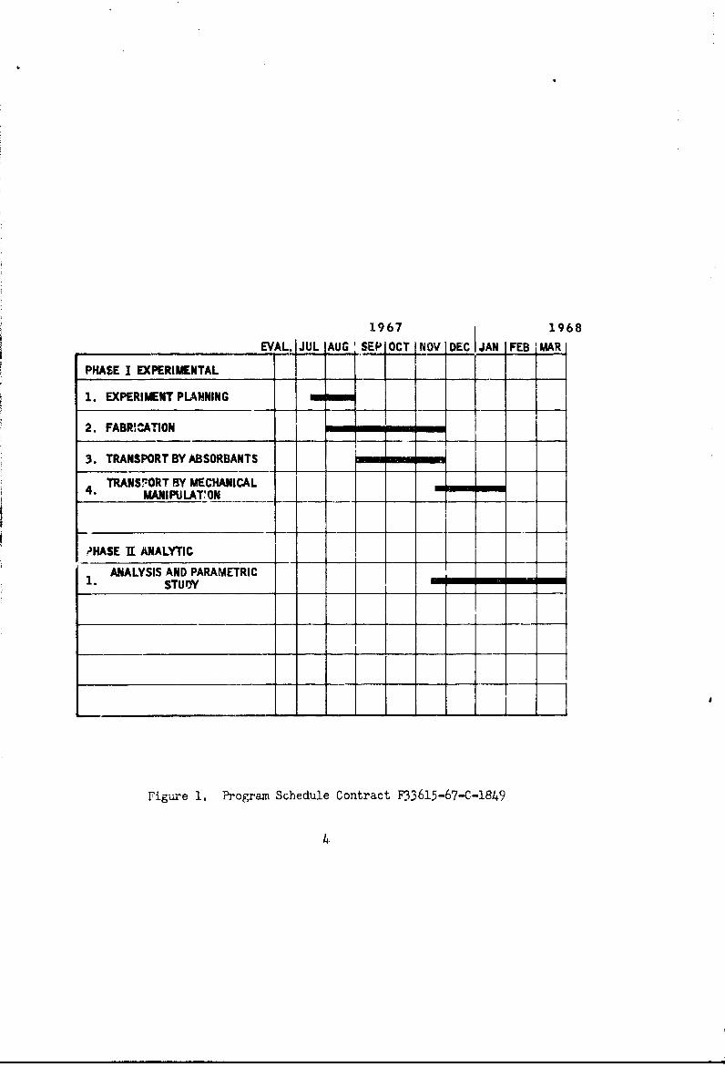
The objectives of this program dictated that the analytical and experi-mental parts of the program could be essentially independent of each other.To assure that the analytical study would take advantage of any technologydeveloped in the experimental study, the analytical study was to start laterin the program with the experimental work on oxygen transport preceding theanalytical study. The general program schedule is shown in figure 1.
EXPERIMENTAL PLAN
The experimental effort was divided into two phases as shown in figure 1.The initial phase involved the evaluqtion of the adsorption-desorption methodof transporting oxygen from a subliming vapor at low pressures and temperat-resto a vapor under the pressure and temperature conditions of a space cabin. Thiswork was to take the form cf experiments to determine the feasibility of theapproach and to provide data to make a preliminary evaluation of the practic-ability of the approach. Tests were planned in which the adsorption of oxygenvapor subliming from solid oxygen would be demonstrated. Tests were alsoplhnncd to provide the adsorption rate of cold oxygen vapor for various tempera-tures of the cryosorption pump. The work was to be done on a laboratory scaleusing solid nitrogen to prepare the solid oxygen.
The second phase of the experimental wcrk was to demonstrate the transportof solid oxygen by mechanical transport from the low-pressure, low-temperaturestorage area to a chamber where the oxygen could be transformed to a breathablecondition. The tests would disclose major problems in this approach and, thereby,provide preliminary information to indicate the best mechanical method to use.This work was to be done on a laboratory scale using solid nitrogen to preparethe solid oxygen.
From a temperature difference standpoint, the best method of solidifyingoxygen is with liquid helium. However, liquid helium is expensive, and its usebecomes impractical for the scope of this feasibility program since the quanti-ties of solid oxygen required could be prepared using solid nitrogen.
ANALYTICAL PLAN
The basic plan for the analytical phase of the program was to evaluate theuse of solid oxygen for a-plication in manned space systems for storage andsupply of breathable oxygen. The study was to evaluate the use of solid oxygento improve the storage life cf oxygen when it is not being consumed, as well asthe use of solid oxygen for storare and supply systems during continuous useby crew members. The application potential of solid oxygen was to be developedby comparison with the use of subcritical and supe-critical oxygen storage.
The work involved in the analytical phase would initially require develop-ing the analytical procedures and then programming these procedures for use onthe IBM 360 dligital computer.
15e
1967 1968
EVAL. JUL AUG S DEC JAN MAR
PHASE I EXPERIMENTAL
1. EXPERIMENT PLANNING
2. FABR'CATION
3. TRANSPORT BY ABSORBANTS
TRANS;'!ORT BY MECHANICALMANIPULAT.'ON
"HASE 1T ANALYTIC
- ANALYSIS AND PARAMETRIC1. STUOY I
Figure 1. Program Schedule Contract F33615-67-C-1849
4
The basis for the study was to be an oxygen storage vessel, thermallyinsulated, and having thermal isolntion supports to handle realistic launchG-loads. The insulation and support methods were to be considered for all.three oxyren storage methods (solid, subcritical, and supercritical) so thatcomparison of optimum designs for each mptho&• can be made.
C;12:E!ý,AL OXYGNIJ FROPERTI:ZS
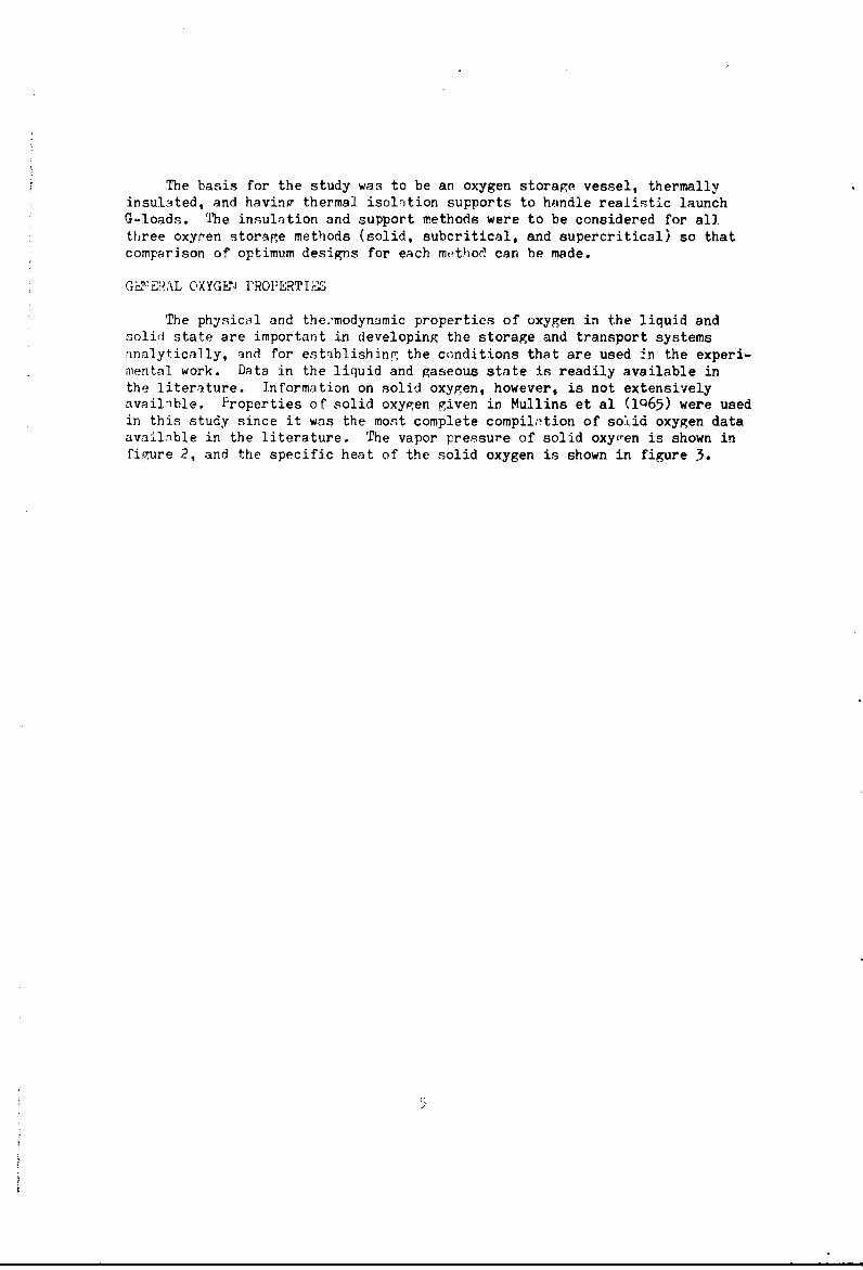
The physical and the.'modynamic properties of oxygen in the liquid andsolid state are important in developing the storage and transport systemsinalytically, and for esttablishing the conditions that are used 4n the experi-mental work. Data in the liquid and gaseous state is readily available inthe literature. Information on solid oxygen, however, is not extensivelyavailnble, Properties of solid oxygen given in Mullins et al (1Q65) were usedin this study since it was the most complete compilation of solid oxygen dataavailable in the literature. The vapor pressure of solid oxygen is shown infigure 2, and the specific heat of the solid oxygen is shown in figure 3.
i)
10-3
10-4
10 -3
10-7ul10" 5
IC BLEI
d1o -
1O-1/ I I I 1
5 10 15 20 25 30 35 40 45 50 55 60
TEMPERATURE, K
Figure 2. Vapor Pr•asure of Solid Oxygon
6

FROM SCOTr (1959)13 _______
12 TMPIL, POINT UQ~LD
"11 554.33 K 1
- SOLID I h= 106.3 COL MOLEW 10 P 43.800 K
"Ah = 177.6 CAL MOLE" 1
8 8~ 7________SOUDR ____ _____
&b 4--h 22.42 CAL MOLE"1
22], 1 /I I I I I I I I o h 1 V 4 8 1 2 4 ' 9 I 1 1 6I I ,~
TEMPERATURE, K
Figure 3. Heat Capacity of O.Vgen in the Solid and Liquid States
I

SECTION III
EEPERIMENITAL STUDY
OXYGEN TRANSPORT BY TUE ADSCRPTION METHOD
O Solid Oxygen Sublimation Labo. Aory Tests
The p•ur•ose of the initil t sts was to determine importantparameters involved in the transport of oxygen from a stored solid to abreathable :?tate by the use of molecular-sieve adsorbents that have beencoo ed to temperatures obtainablu by passive radiation to spdce.
Test Arparatu.g
The basic arrangement for this first experimental testis showr schematically in figure 4, and the working vessel for preparingaind storing the solid oxygen i5 shown schematically in figure 5. Aphotograph of the complete test system for transport bj adsorbents isshown in figure 6.
The working vessel consists of a double-wall containerwith associated filling and evacuation lines, a pressure sensing tube,and art evacuati3n line leading into the space between the double walls.The space between the douible walls can be evacuated to provide an insu-lation space or filled with helium gas to serve as a thermal conductor.The pressure sensing tube from the oxygen container was connected to apressure gauge to indicate the state of the oxygen.
The cryosorption pump provides a low pressure overthe stored oxygen and acts as a collector and pressure raising devicefor the subliming oxygen. Valves are provided so that the pumps can ,ealternately and sequentially removed from the low-temperature bath formeasurement of the amount of oxygen evolved at a breathable pressure.By using three cryosorption pumps, this c,n be Tone on a continuousbasis.
The gaseous oxygen de-absorbed from the cryosorptionpumps by heating was condensed and measured. This was done in thecollection and measuring apparatus sho-rn in figure 6. Condensing wasaccomplished by surrounding the oxygei, collection tube with liquidnitrogen. The amount transferred was determined by measuring the levelof the liquified oxygen with a cathetometer.
Test Operations
Procedure
The procedure for operation of the test systemwas as follows (see figure 4):
8

Closed Open
Warming
To HeliumGaa Supply
S •Liquid Oxygen Open Closed
To Vacuum
-r T- Pumping
Model K- I __
Dewar Cold ConstantTemperature
BathNitrogen
t
Closed ] Closed
Solid Oxygen
Storage
_ _ _ Container
SN2
CryosorptionPumps
Figure 4. Experimental Setup-Transport by Adsorbents
9

Stainless Steel Tube Stainless Steel Tube1. 25 em ID, 0. 25 mm Wall Thickness 0. 95 cm ID,
0. 25 mm Wall Thickness
Stainless SteelCapillary Tube,0. 5 mm OD
0-Ring
625.0.K- 1 Dewar
Stainless
Steel Inner SolidifiedContainer Nitrogen0. 5-mm
Thick Wall
25 cnr 30. 5 cm
26 cm
Copper Outer___J" Container
2.53 mm
2 cm Thick Wall
Figure 5. Solidified Oxygen Storage Container
10
Figure 6. Experimental Apparatus - Transport by Adsorbents
l1

1. The test Dewar is partially filled with liquidnitrogen.
2. The space between the double walls of the work-ing vessel is evacuated, and the working vessel and Dewar cover areinstalled in the test Dewar.
3. The inner container of the working vessel isfilled with liquid oxygen and the fill line sealed.
4. The space between the double wa•ls of the work-ing vessel is filled with helium that provides a thermal conduction pathand allows the liquid oxygen to cool to the liquid nitrogen temperature.
5. Vacuum pumping reduces the pressure in the testDewar, causing the nitrogen to solidify ana cool to temperatures of about48 to 50K.
6. The solid nitrogen then cools the liquid oxygenthrcugh the helium space to a temperature where it solidified (54.36K).
7. After the oxygen is solidified, the helium isevacuated from between the double walls of the working vessel, and thesolid oxygen, under vacuum storage conditions, is now available for theadsorption experiments.
8. The cryosorption pumps are then cooled and con-nected in sequence to the solid oxygen 3torage container. The pumps areallowed to adsorb the sublimed oxygen at a pressure of 1.14 torr or less.After adsorption on a pump is completed, the pump is isolated from thesolid oxygen container by means of valves, and the pump is warmed todeadsorb the oxygen at a considerably higher pressure than the vaporpressure of the solid. The deadsorption pressure was 150 torr forthese tests (the vapor pressure of oxygen at 77K).
Shakedown Operation
Initial operations with the test system dis-closed two areas in the test apparatus requiring modifications.
First of all, the solid nitrogen in the testDewar surroundi.ig the working vessel could not be cooled by vacuumpumping to a temperature sufficiently low to solidify the oxygen usingthe e:sting equipment. The lowest temperature that can be achievedby vacuum pumping over a solid quch a.ý nitrogen is a function of itsevaporation rate. To lower the sublimatfin temperatur- of the solidthe vacuum pumping system should be inciased in size, and/or the heatleak into the vessel reduced. The system was modified by increasingthe capacity of the vacuum pump from 14.2 to 38 liters per second, anda low-emissivity shield was placed between the surface of the nitrogen
12

and the cover of the test Dewai. These modifications increased theevaporation rate and reduced tle heat leak rate to the point where anitrogen temperature of 50K was obtained as shown by the pressuremeasured over it of 3 torr. This temperature is sufficiently lowerthan the 54.36K required for solidifying oxygen.
The second problem was that the oxygen inthe inner container of the working vessel would not solidify in areasonable length of time when the solid nitrogen temperature wasaround 50K. The heat transfer rate between the solid nitrogen andthe oxygen was not suffic.ient. The two major causes of a low heat-transfer rate are the thermal resistance of the helium transfer gasand the thermal resistance of the gap created by the solidifyingnitrogen.
To evaluate the cause of the heat transferproblem, a special test was conducted using liquid nitrogen in theinner container of the working vessel where oxygen is normally con-tained. The test Dewar was charged with about 75 liters of liquidnitrogen and the inner container was loaded with 0.88 liters of liquidnitrogen. The intermed.iate volume between the two nitrogen areas wasfilled with helium gas at a press re of 1.06 kg/cm absolute. The testDewar containing the 75 liters of liquid nitrogen was then evacuated byconnecting it to the vacuum pumps.
Figure 7 shows the temperatures observed in thetest apparatus from the vapor pressure measurements in each nitrogencontainer. The pump-down curve for the evacuated nitrogen in the testDewar is shown as curve II. The section of this curve from "a" to "b"shows nitrogen as a liquid; from "b" to "c" the nitrogen is solidifying,and from "c" to "d" the nitrogen is a solid and continues to drop intemperature with continued Dumping. Curve I in figure 7 shows the tem-peratures during cool-down o± the nitrogen in the inner container, andcurve III shows the heat transfer rate between the nitrogen in the innercontainer and the nitrogen in the test Dewar as calculated from thetemperatures and the properties of the materials. It is apparent fromcurve III that the rate of heat transfer decreases appreciably after thenitrogen in the Dewar solidifies, approaching 15 calories per minuteafter two hours. To determine whether the unexpected heat transferresistance was through the helium gas or in the nitrogen, calculationswere made. The heat transfer through the helium gas was over 30 caloriesper mi.-te by conduction alone, and therefore the helium was not the sourceof the •normal resistance. The calculations indicated that a gap betweenthe solid nitrogen and the inner container of about 0.01 cm would give aheat transfer rate of 15 calories per minute. Therefore, the reason forthe high heat transfer resistance between the solid nitrogen and theinner container was the presence of a gap at this interface caused bythe subliming nitrogen. To solve this problem by reducing the effectsof gap resistance, copper conduction strips were attached to the bottomof the working vessel and extended into the solid nitrogen auea in thetest Dewar. A sketch of this modification is shown in figure 8. The
13

80 240
I COOL-DOWN RATE OF LIQUID
76 200 -- NITROGEN IN INNER CONTAINER
"T COOL-DOWN RATE OF VACUUMPUMPED NITROGEN RATE INC.aWARz
"m" HEAT TRANSFER RATE FROM72 u160 INNER CONTAINER TO NITROGEN
IN DEWAR
64 • 80 \ . •............
60 40
560 20 40 60 80 100 120 140
TIME, MINUTES
Figure 7. Test Results for Heat Transfer Evaluation
14
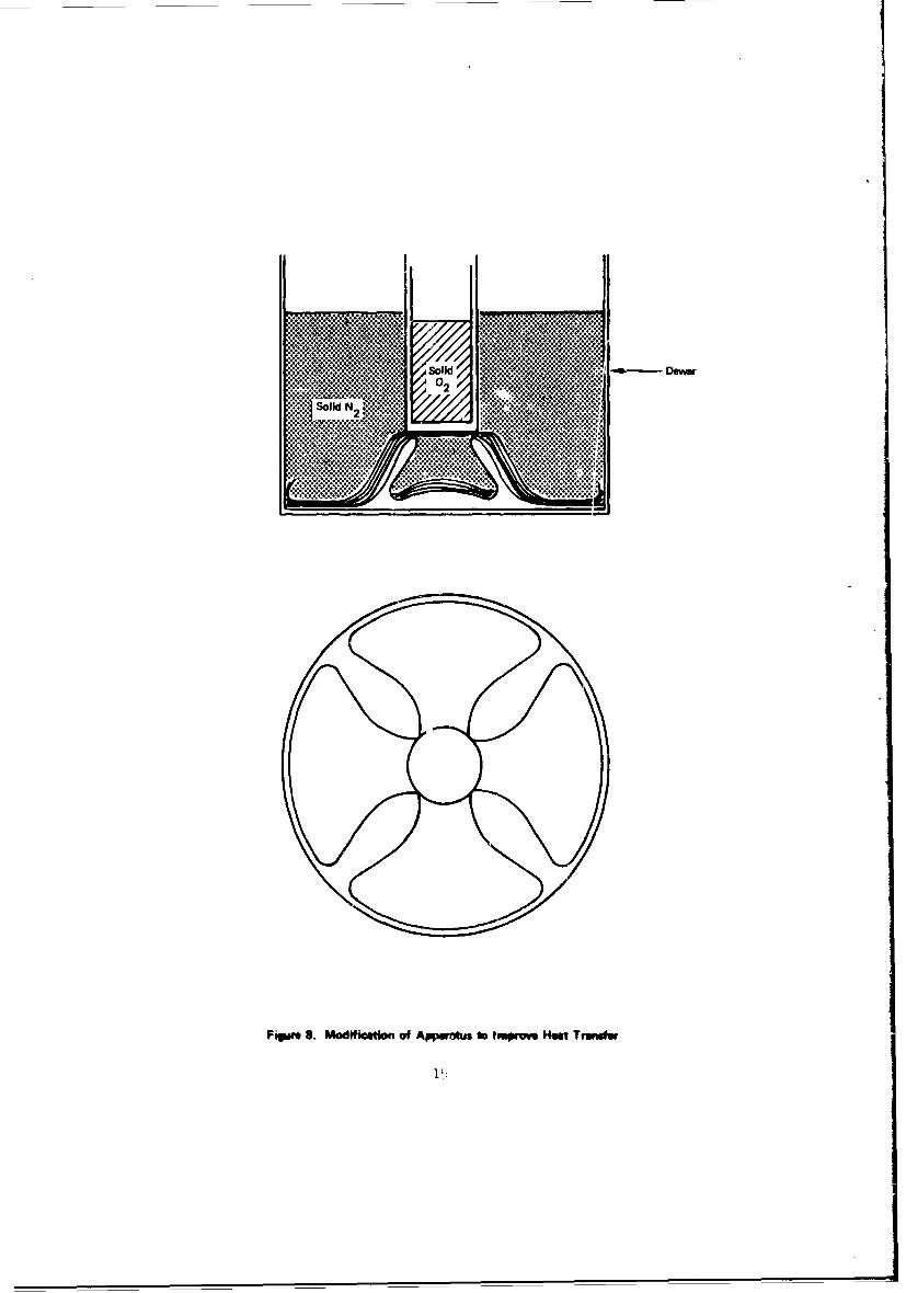
So Sodi N2 .
Fele .Moiictono Apreu ~ emrw.HatT0wt
2'

tests described in the next section indicated that these problems
were satisfactorily solved by the modif'iations that were made.
Test Runs
Two test runs were made in which solid oxygenwas prepared in the working vessel and the subliming vapors collectedon the cryosorption pumps. The oxygen in the pump was driven off byheating the pump. The amount of oxygen collected in the pumps wasmeasured by condensing the vapors in a calibrated glass tube immersedin liquid n'trogen and determining the liquid level with a cathetometer.
Test Run No. 1
The test Dewar was filled with liquidnitrogen. Oxygen from a gas bottle flowed through a coil immersed inliquid nitrogen, where it was liquefied, and then it passed into theinner container of the working vessel. Helium jas was added to thespace between the vessels to a pressure of one atmosphere. The testDewar with the liquid nitrogen was then connected to the vacuum pumpand evacuation started. Table I shows the pressures measured in thenitrogen Dewar and oxygen container during pump-down.
The helium was pumped out from the spacebetween the solid cryogens to thermally isolate the solid oxygen, andthe cryosorption pump tests started. The pumps were connected to thesolid oxygen in sequence, and after disconnecting, they were allowed towarm up. To accelerate the warm up of the pump, an electric heater wasinserted in the center cavity of the pump, isolated from the molecularsieve by the casing. The oxygen was transferred to the measuring tubesby using the pumps until the pressures in the test system indicated thatfurther transfer was impractical. The amount of gaseous oxygen trans-ferred by the cryosorption pump in this test was about 3 cc in tne con-densed liquid state.
Test Run No. 2
This test run was similar to No. 1 exceptthat the cryosorption pumps were more extensively activated to eliminateall traces of moisture in the molecular sieve. Activation was accom-plished by heating the pumps to 240C u'Aer vacuum until the pressure onan absolute pressure gauge read zero. _n this test, 10.0 cc of condensedliquid oxygen were transferred to the 0.625 cm ID and 2.19 cm ID oxygenmeasuring tubes as a gas.
Test Run No. 3
This test was a repeat of test run No. 2.In this test, 20.0 cc of condensed oxygen were transferred by using allthree oxygen measuring tubes, the 0.625 cm ID, ths 2.19 cm ID, ard the2.50 cm ID tubes.

TABLE [
TEST SYSTEM PUMP DOWN
OXYGEN TRANSPORT BY ABSORPTION METHOD
Run No. 1
Pressure of nitrogen Pressure of oxygen in workingin test dewar, vessel container,
Time mm Hg mmHg
0857 83 - solid nitrogen --
0932 42.3 80
0945 29.5 68.5
1007 13 57
1025 8.4 52
1040 6.5 49.4
1055 5.5 48
1120 4.5 46
1200 3.5 43.5
1300 3 42
1326 2.6 1.2 - solid oxygen
1327 2.6 1
17

Test Besults
The feasibility of trane'orting oxygen fromthe subliming solidified state, occurring at 1.14 torr or less, to apressure sufficiently high to breathe was successfully demonstrated.An approximate 200:1 compression of the oxygen vapor was acconmplishedusing thermal energy; no mechanical energy was used or required.
The rate of oxygen trans port from the solidifiedcondition by means of a 5A type molecular sieve (synthetic zeolite-calcium alumna silicate) was 0.0854 gram per minute for 0.725 kilogramadsorbent at 77K. For one man, 0.785 gram per minute are required, andthe adsorbent weight requirement would be 6.7 kilograms.
Because the rate of oxygen transport was limitedby the flow conductance of the apparatus tubing and the valves, andquantitative values obtained in these tests can not be consideredoptimum. This factor dictated that tests should be conducted to spec-ifically obtain quantitative data on the adsorption capabilities oforxgen on the molecular sieve. This type of data would be useful indeveloping the practicality of the cryosorption method of oxygen trans-port. The next section desc2ibes the tests to obtain this data and theresults of the tests.
Cryoso-ption Pump Adsorption Laboratory Tests
The major factor determining the efficiency of the cryo-sorpcion pump, oxygen transport system is the effectiveness of the adsor-bent. The previous tests provided preliminary data, but due to systemlimitatione, the quantitative adsorption capabilities of the adsorbentscould not be obtained. The tests described below were directed to obtain-ing the amount of oxygen that can be adsorbed per unit weight of molecularsieve at a given temperature.
Test Apgaratujs
The test apparatus for thesa experiments used ths cryo-sorption pumps from the previous test (see figure 6). The oxygen col-lection and measurement apparatus shown in figure 6 was used for theliquid oxygen supply and for measuring the quaistity of oxygen adsorbedon the cryosorption pumps. The level of liquid o-ygen in the precistonbore tubes of the oxygen supply system was determined by using a ctneto-meter. A schematic of the test arrangement is shown in figure 9.
Teat Operationo
Prior to edch test, the molecular sieve was- activatedby heating to 477K for six hours while purging with dry nitrogen andthen vacuum pumping for one hour at a pressure of 10-2 torr.
V3

F Slillow Rubber
Absoluteprom". SN-2
Gap Cryoorption PuWii
Vacuum PumW
PinchCup
GM
02 - F2mn
Cylminar Ii
S0ke 2 . I 062 a 2.bc 25cvcoilsyow~ D D I
Pump1111
lelium hhov*V Refsonce M
Leieiamr ofLiu
Levelo Liu ids
Fipme 9. Sdumiuse of Too Arw*.'= fmt O~yVW Adwrpbo Ta

The adsorption tests were conducted with the molecularsieves at two temperature levels. A temperature of 195K was obtained bysubmerging the cryosorption pump in a CO -trichloroethylene bath, and a
temperature of 77K was obtained by submerging the pump in a liquid nitro-gen bach. Three molecular sieves, designated 5X, IOX, and 13X, weretested. These were standard molecular sieves as furnished by Linde andhave 20 percent inert material as binder.
These tests were conducted in the following manner:
a. The cryosorption pump was submerged in the coolantand the pump cooled to the test temperature level.
b. The glass Dewar flasks surrounding the oxygensupply tubes were filled with liquid nitrogen.
c. Gaseous bottled oxygen was put into the oxygensupply tubes and condensed by the liquid nitrogen.
d. After the level of liquid oxygen was measured, thevalve between the oxygen suppl[' tube and the cryosorption pump was opened.
e. The pressure in the pump was measured with a pre-cision McLeod gage, and the liquid oxygen level was measured with a cathe-tometer at intervals during adsorption until equilibrium was achieved.
The initial tests indicated that this procedure wassuitable for obtaining the data necessary to generate the desired per-formance. Each of the molecular sieves, type 5X (calcium alumina-sili-
cate), type lOX (crystalline alumina-silicate), and type 13X (sodiumalumina-silicate), was evaluated at temperatures of 195K and 77K. Noproblems -ccurred during the test operations.
Test Results
The results of the tests are presented in figure 10.The fixst important f-ature nwted on the curves is the large differencein the quantity of oxygen adsorbed at the two temperature levels. Thispoints out the importance Gf operating the cryosorption pumps at thelowest possible temperature level during the adsorption phase of operation.
The curves in figure 10 show a significant differencein performance of the three molecular sieves. The lOX type adsorbed-;proximately 10 percent more oxygen than the 13X type and about 25 per-cent mcre than the 5X type for a given pressure level at 77K. The 13Xmolecular sieve performed very poorly at 195K compared to the other twotypes. The quantity of oxygen adsorbed. by the 13X sieve was almost neg-ligible, although the lOX and 5X sieves only adsorbed about I gram ofoxygen per 100 grams of adsorbent for these sieves tit 77K.
20

2
IX IXoo00
AT 195 X13X S
o~ 10 20 3PRESSURE, TORR
40lux
~30
20
AT 77K10
II X
0 10 20 30PRESSURE, TORR
Figure 10. Adsorption Isotherm, 02, on Molecular Sieve at 77K and 195K
21

The data shown in figure 10 indicates that of the
three types tested the IOX molecular sieve is best suited for oxygenadsorption. The isotherms in figure 10 include the adsorption capa-
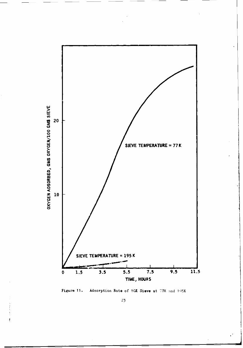
bility of the lOX sieve which should be used in the system study.Figure 11 is a plot of the oxygen adsorption rate for the lOX molecular
sieve at 77K as determined from the test data. The information on thelOX molecular sieve in figures 10 and 11 can be used for preliminaryperformance evaluation of the cryosorption-pump, oxygen transport system.
Evaluation and Application of Results
The results obtained in these tests are suitable for pre-
liminary evaluation of the performance of the cryosorption pamp. Theevaluation is limited to an operating temperature level for adsorptionof 77K since only 77K and 195K temperature levels were evaluated in theteots, and the latter temperature level showed insignificant adsorption.
The information on the cryosorption pump performance thatwould be required for the oxygen transport system study includes thesize of pump necessary for transporting a given amount of oxygen fromthe subliming condition to a breathable state. In addition, the ratesof adsorption, deadsorption, and cool-down of the pump are necessary toestablish practical cycling conditions and to determine the number ofcryosorption pumps required.
Using the data from figures 10 and 11 for the lOX molecularsieve, the adsorption time required for various adsorbent weights can bedeveloped for a given oxygen transport rate. A cyclic process is nec-
essary for the cryosorpti(,n-pump transport method to maintain a constantoxygen supply rate. One pump is deadsorbing oxygen to the crew compart-ment while the other pump is adsorbing the oxygen that is subliming fromthe solid. The pumps are then switched over to the opposite processwhen the adsorbing pump is loaded with oxygen. Given an oxygen supplyrate requirement of 2.26 kilograms per day, the cycle time and adsorbentweight requirenents are shown in figure 12, This curve indicates that aminimum adsorbent weight exists for a cycle time of 6 hours. Operationwith cycle times of less than 6 hours will result in less than optimumcapacity of oxygen adsorbed on the molecular sieve (figure 11). With acycle time greater than 6 hours, the rate of oxygen adsorption beyondthe 6 hour period falls off as shown by figure 11, so that operation inthis region becomes less efficient. It should be pointed out that thedata in figure 11 was developed from one test and must be consideredpreliminary. The weight of the molecular sieve for one cryosorption
pump is shown in figure 13 for various cycle times as a function ofoxygen flow rate.
The other information required to evaluate the performance
of the adsorbent transport system is the deadsorption rate of themolecular sieve and the cool-down rate of the cryosorption pump after
it has been deadsorbed of oxygen !ýnd prior to the next adsorption cycle.
20
zSIEVE TEMPERATURE 77 K
U)
macc0U)
0 1
SIEVE TEMPERATURE =195 K
0 1.5 3.5 5.5 7.5 9.5 11.5
TIME, HOURS
Figure 11. Adsorption Rate of lOX Sieve at 77K !ind lk)5K
23

ADSORBENT REQUIRED IN EACH OF IWOCRYOPUMPS TO SUPPLY 2.26 KGOXYGENPER DAY
(MOLECULAR SIEVE lOX AT 77 K)
10
9
8
7
6
=5
F4
. 3
2
1
I I I i I I I I
0 0.5 1.0 1.5 2.0 2.5 3.0 3.5 4.0 4.5 5.0
ADSORBENT REQUIRED, KILOGRAMS
Figure 12. Adsorbent Weight as a Function of Cycle Time
24

The deadsorption of oxygen from the molecular sieve should be rapid atroom temperature since figure 10 indicates that the adsorbed amount ofoxygen in equilibrium with the lOX molecular sieve at 195K is almostnegligible. The cool-down rate of the cryosorption pump used in thetest was approximately determined from visual observations of the liquidnitrogen bubbling when the pump was immersed in liquid nitrogen for cool-ing. The liquid nitrogen bubbling essentially stopped after 30 minutesof immersion. A transient analysis for this annular sieve container 2
gives a value of 45 minutes using a thermal diffusivity value of 9.29cm /hr,and assuming that the thermal resistance between the pump and the coolantis negligible. Since this is reasonably close for approximate analysis,the cool-down rates for cylindrical cryosorption pumps of different sizeswere calculated using these assumptions, and the results are shown infigure 14. The molecular sieve requires long cool-down times, 6 hoursfor a 0.5 kilogram cryosorption pump for example, and therefore, a three-pump system would be necessary for oxygen transport. One cryosorptionpump is being cooled down, one pump is adsorbing oxygen, and one pumpis deadsorbing oxygen. Therefore, to obtain the basic molecular sieveweigiit of the cryosorption-pump, oxygen transport system, it is necessaryto multiply the weight in figure 13 by three for the three cryosorptionpumps.
The cool-down rate can be improved by filling the molecularsieve with a material having high thermal conductivities, such as,aluminum or copper wire mesh, or else strip finL could be used torapidly conduct the heat out of the adsorbent. These deuices willadd tc the weight and the complexity of the structure. Further studyof these methods would be required to establish the best method to u~eand the penalty associated with the modification.
The system analysis conducted in the analytical study assumesthat the aasorption rate of oxygen on the molecular sieve dictates thecycle time and that a three-pump system is required. These are reason-able assumptions for a preliminary evaluation of the system, and furtherexperimental and analytical study would be required on the deadsorptionand cool-down pha-,us for a complete system design study.
OXYGEN TRANSPORT BY MECHANICAL MANIPULATION
Laboratory Tests
The basic goal of this experiment was to demonstrate thefeasibility of transporting solid oxygen by mechanical means from avacuum storage space to a pressurized area via an air lock. In thislatter condition, it wovld be available as breatVing oxygen for crewu.e init man ned space vehicle and for extra-vehicular activity.

26
<24C3,0o,22 CYCLE TIME
0. 2 HOUR"
=20 _
Of 4 HOURW18 -
zS,6 HOUR,.
014 -
<: 8 HOUR',' 810 x MOLECULAR SIEVE
~12 77 K ADSORPTION TEMPERATUREU/)
,10
0
'a-o6
- 4
20 2 4 6 8 10 12 14 16 18 20 22 24
OXYGEN FLOW RATEKILOGRAMS PER DA"'
1 1 i 1 10 5 10 15 20
EQUIVALENT NUMIBER OF CREW MEMBERS
Figure 1.5. Adsorbent Weight Required as a Function of Oxygen Flow Rate
26

100COOLDOWN RATE80CRYOSORPTION PUMP
60 - OX MOLECULAR SIEVE
CYLINDER, LENGTH = DIAMETER
40 NO COOLANT THERMAL RESISTANCE
77 K COOLANT TEMPERATURE
COOLDOWN TIME IS TAKEN ASTIME FOR CENTER OF CRYOPUMPTO GO FROM 300 K TO 90 K
20
0
z8
-9 6
4
2
1, 4 6 8 10 20 40 60 80 OO
PUMP DIAMETER, CM
.2 .3 .5 1 2 4 6 10
W'T, v"'.OGRAMS
Figure 14. Cooldoas, Rate of Cryoaorption Pump
27

Preliminary Experiment
While the basic test apparatus for conducting thesetests was being fabricated, a preliminary experiment was conducted withglass vessels (figure 15) to develop the method of preparing the solidoxygen and to visually observe some operations of moving the solidoxygen. Figures 16 and 17 show the solid oxygen formed in this system.The oxygen was condensed and cooled inside the inner vessel by theliquid nitrogen surrounding it. The atmosphere over the liquid oxygenwas connected to a cryosorption pump which was cooled to 77K. Thepressure over the oxygen was reduced to the point where the oxygensolidified (1.14 torr).
Since oxygen is paramagnetic, an attempt was made topick up the solid oxygen with a magnet. As shown in figure 17, thesolid oxygen was picked up by the magnet, but it is suspected that amajor influence was played by the oxygen freezing on the magnet sincethe magnet was initially warm. Th3 warm magnet rmelted a small e-olintof solid oxygen in contact with it, and then, after the magnet becamecold, this liquid oxygen solidified on the magnet's surface.
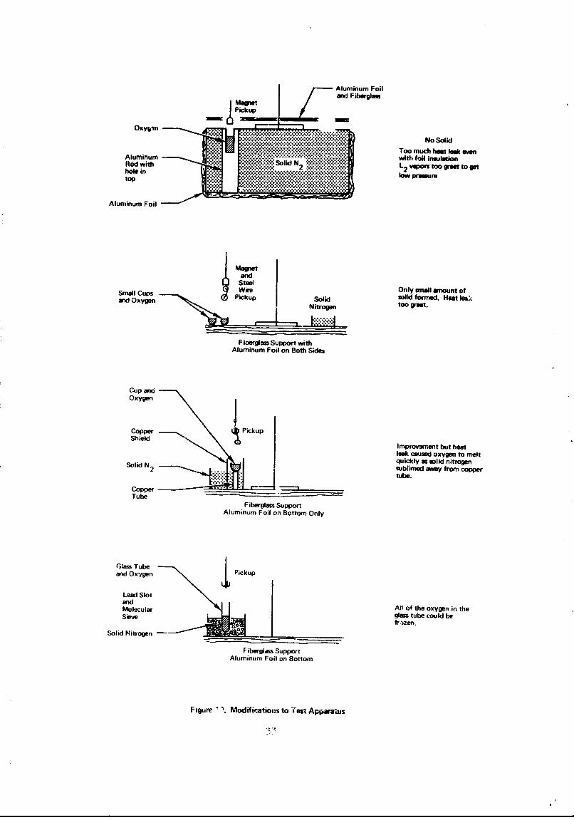
The initial test apparatus was designed to solidifythe oxygen by having the cavity of liquid oxygen in contact with solidnitrogen. When the pressure over the solid nitrogen is reduced below1.14 torr, the temperature of the nitrogen is below 54.36K, sufficientto solidi Wv the oxygen. Solid oxygen was formed under these conditionsfor the experiments after several modifications were made to the testapparatus to achieve the required temperature and pressure conditionsin the oxygen. Initial tests with the system indicated a radiationheat leak to the oxygen and a loss of good thermal contact between theoxygen and the solid nitrogen when the nitrogen solidified. It wasalso found that because of the large mass of solid nitrogen in thesystem (figures 18 and 19a) and the limited pumping capacity of thevacuum pump, it was difficult to reduce the vapor pressure over theoxygen to the point where the oxygen would solidify (1.14 torr).
To resolve these problems, modifications wure madeto the system to reduct the mass of solid nitrogen used for cooling theoxygen (figure 19). The goal was to get the vapor preL:sure over theoxyren to below 1.14 torr while keeping its temperature below 54K. Thefirst modification used a Fiberglas plate (figure 19b) on wi.ich a copperstrip was mounted. Copper oxygen buckets and a container for N, were
located on this strip. Cooling of the oxygen bucket.; was accomplishedby the solid nitrogen through the copper strip. This ocheme made itpossible to obtain a low vapor pressure, approximately I torr, overthe crygen, but the radintion heat transfer t) the large copper itrip.surface was too great to lower the oxygeni temperature much below the54K requir-d. A smnll amount of soli oxygen was formed but cc:.;-i:o-tent formation of solid oxygen could not be nccomplizO)ed.

VeccoFitting
MetalAdapter
Vacuum
RubberConnection
G lass .. Sealed at theDewarBottom of Dip Lag
Dewar g ..Puimr p~u otP~ergSldO~p

Yiguzeif. t~~7eraI flow:17 Eelixairnary SoI'd Qye~Že~n
30

Figure 17. Solid Ouxgen Crystals Being Raised with Magnet
Ii

- Compound Pressu~e Gags
01 RefRecorder
Wire ~Thermoccuple .
Pressure Comp~ound
Gage
FittingsGa
Glea~ub Veco Vc -Heliumn
Turiing To Oxyjen Glass
'swy Wall Iad Cylinder
5ok1 2 -- Condensirng Bucket
Valve InClosedPosition
*' EGlassV Idow,
5, Lae lunn_ _ 1 Layer Fiberglass
Dewar
SSo.o lkltrogi~n
I Aluminum FoilI~I n~ulption
Figure 18. initial Design of Test Apparatus - Solid Oxyg-ri IV,-hanical Transtjorts
Aluminum FoilMagnetanid Fiberglass
No SolidToo much heat leek eoen
Alumwinum with foil insulation...d ewi. 12 vapor$ too great to guthole in W.pfU5WV.
top..lwpesr
Aluminum Foil
SmallCup$WireOnly small amnount ofand Oxygen PikpSolid solid formed. Hoea lea'(
Nitrogen to weea.
Fiberglass Support withAluminum Foil on Both Sides
Cup andOxygen
CopperPickupShield
Improvement but heatleek caused oxygen to melt
Soli N 2quickly as solid nitrogensublimed away from Coppertube.
CopperTube
Fiberglass SupportAluminum Foil on Bottom Only
Glass Tubeand Oxygen Pickup
Lead SlotMoldcular All of the oxygen in theSolecula glass tube could be
Sieve ~fr 'zen.Solid Nitrogen
Fiberglass SupportAluminum Foil on Bottom
Figure \Mod ifi'lations to -fest Apparauis
The oxygen bucket was then moved into closer contactwith the solid nitrogen as shown in figure 19c. Solid oxygen could bereadily formed with this arrainement, but the quantity was relativelysmall and problems arose in removing the oxygen from the copper bucket.Small wire forms inserted in the solid oxygen aided in lifting thesolid oxygen.
The configuration which was found most suitable is thatshown in figure 19d, in which a glass oxygen bucket was used. A mixtureof molecular sieve and lead shot was added to the liquid nitrogen toimprove its operation by helping to maintain good thermal contact withthe oxygen bucket. This system worked satisfactorily and solid oxygencould be readily formed in the glass bucket for transport studies. Thecomplete final test system is shown in figures 20, 21, and 22.
Tent Operations
Several methods of mechanically moving the solid oxygenwere attempted with this equipment. These involved picking up the solidoxygen with a magnet and with hooks.
The use of a magnet for moving the solid nxygen has
merit in that on-and-off control can be obtained if the magnet is anelectromagnet. The initial attempts to lift solid oxygen using itsparamagnetic properties, discussed previously in the preliminary studysection, were inconclusive. Further tests were tried using the newapparatus but with the same results. The solid oxygen could be liftedwith a magnet, but the ability to do so was so marginal that freezingof the oxygen on the magnet probably was the primary mode of adhesion.However, lifting the solid oxygen by using its paramagnetic propertiesis not ruled out by these preliminary experiments. The experiments didshow that the problem is complex. Stronger magnets and better contactof the surfaces between the oxygen and the magnet may be required.
The solid oxygen could be lifted with a magnetindirectly by placing a small steel-wire coil in the oxygen prior tcits freezing; the solid oxygen was easily lifted with the magnet in asimilar manner so that proposed for the paramagnetic oxygen method.
The solid oxygen was also lifted as shown in figure
19c by using a fishhook in conjunction with a looped wire in the solidoxygen. This method posed no problem manually but might be difficultto set up for automatic operation.
The final method tried was to use a wire hook arrange-ment submerged in the oxygen during the solidification phase. The fullamound of solid oxygen formed in the vessel could be readily lifted outof the glass tube by this method. Solid oxygen was lifted through anair lock val-e by this method, as shown in figuriý 23. When the air lock
34

AbsoluteSPressure Compound
GagpI eLead
GlassWindow
SolidOxygen
-- Oxygen- Condensing
-Coil
Valve .n
Position
GlassWindow 6 Layers of
Vac Insulation (A1)
Glas~ub -- - - ______ ______Fill Spout
Molecular Sieveand LN2
Aluminum Shield
Figure 20. Final Test Arrangement - Solid Oxygen Mechanical Transports

Figure 21. Internal Arrangement of Solid OxygenMechanical Transport Test System
36
Figure 22. Overall View of Solid Oxygen Mechanical Transport Test System
37

Figure 23. Solid Oxygen in Pressure Ch,--mber
38
valve is closed, the oxyg6n melts, evaporates, and is ready for breathingunder the pressure conditions existing in the area above the air lockvalve.
Discussion of Test Results
Various methods of preparing and mechanically trans-porting solid oxygen were studied. For economy, the preparation of solidoxygen was restricted to using solid nitrogen as a coolant, although theuse of liquid helium or neon would be much more suitable in a practicalsystem. Mechanical methods could readily move the solid oxygen by usinga wire-hook lifting device with or without a wire coil in the solidoxygen. The solid oxygen could be lifted with a magnet if a steel wirecoil wes located in the solid oxygen. Direct lifting cf solid oxygenusing the paramagnetic characteristics of solid oxygen was not con-clusiveiy demonstrated, and further study would be required in this area.The practical application of these methods or similar metho-i.s of mechan-ically moving solid oxygen, must consider the overall requirements ofthe oxygen supply systep.
Evaluation and Application of Results
The experiments demonstrated Lhat solid oxygen can be trans-ported frcm a vacuum storage space to a chamber where it can be convertedinto a breathable conditaon. The solid oxsge, ma.ss was moved through anair-lock valve and then isolated from the vacuum storage volume. Thismethod of oxygen transport appears completely realistic, and the applicationof the method should entail no major problems.
In the experimental test, the solid oxygen was moved throughthe air-lock valve by manually lifting the oxygen solidified around awire hook. An electromagnet can be used to transport the oxygen mechan-ically if a wire coil is frozen into the oxygen when it is prepared. Forautomatic operation with multiple transfers, the basic method testedwould be mcdified depending on the specific application requirements.For example, ice-cube trays of solid oxygen cubes could be prepared withwire coils frozen into each cube. An electromagnet pickup could thenattach itself to a cube when turned on, and the oxygen cube moved throughthe air-lock valve. After the solid oxygen cube is in place, the rlectro-magnet is turned off releasing the cute and the cycle repeated as re-quired. The actual method selected for a given -,pplication wouid be theresult of a study for the specific requirements of the application
DISCUSSION OF EXPEUIMENTAL RESULTS
The experimental work has demonstrated the feasibility of trans-porting oxygen from the solid state to a condition suitable for breathingby two methods, the cryosorption pump method and the mechanical transportmethod. Data was also obtained on the adsorption of oxygen on molecularsieves for use in determining the size of cryosorption pumps required fora practical system.
59

The transport of oxygen involved no major problems. The greatestdifficulty in the experimental work was encountered in preparing thesolid oxygen using solid nitrogen as the coolant. This probizm wouldnot exist in any practical system since the oxygen could be solidifiedwith liquid helium or neon.
The practicality of these two methods for oxygen transport in anygiven system will have to be developed. The major factor determiningthe practicality of the adsorbent transport system for any given appli-cation will be the size and weight of the system. In addition, themodification of the basic system to achieve fast cool-down rates willfurther increase its weight and size. The major factor determiningthe practicality of the mechanical transport method will be the capa-bility to develop a mechanical system which can operate reliably andwhich can nrovide oxygen at a rate to meet the demand requirements.
The mechanical oxygen transfer system has the advantage of beingmore versatile as well as being potentially simpler. Since the oxygenis transferred as a solid, the volume being handled in the transfer issmall and small transfer passages can be designed into the system. Theadsorbent transfer method, on the other hand, requires lalje flow areasbecause of the low gas pressure, and a practical system design usingthe adsorbent method could be a problem for many requirements. Thesolid transfer system could be used for space cabin oxygen, for sup-plying oxygen for extra-vehicular activity, and for quick oxygen sup-ply from a long-term storage container in an emergency.
The mechanical transfer system is therefore considered to be themost promising of the two transfer methods examined. The design andoperation mf a breadboard test system involving this concept would bethe next step in the experimental evaluation of oxygen transport fromthe storage state to a breathable state.
ho

CECTION IV
ANALYTICAL STUDY
OBJECTIVE
The objective of the analytical portion of the study was to performa parametric analysis of the storage of oxygen for breathing purposes inspace. Oxygen stored as solid, osubcritical liquid, and supercriticalfluid was studied for comparing various storage performance parameters.
By starting with solidified oxygen, instead of the saturated liquid
for either the subcritical or supercritical storage systems, advantagecan be taken of the sensible heat capacity, heat of fusion, and increaseddensity of the solid to increase its storage life. This can be done forthe subcritical storage system by launching it as a solid and then allow-ing it to liquefy after Ihunch. Similarly to increase the storage lifeof oxygen in a supercr 4 tical system, the storage Dewar would be initiallyfilled with solid oxygen which would first be allowed to liquefy afterwhich it would be allowed to change to the supercritical state.
In lieu of transformir.g the oxygen, it can be maintained by sub-liming it to space in the solid state, from which condition it is trans-ported to a breathable condition. A combintion of the two methodsinvestigated in the experimental study (transport by adsorbents and by2:echanical manipulation) could be used to achieve maximum usage of thesolidified oxygen. An example fould be the case in which a portion ofthe solid oxygei. is sublimed to space prior to liquefaction. Insteadof wasting that part of the oxygn which would be lost to space, itcould be sublimed to adsorhents ;hat would be used to raise its pressureto a breathable level.
Apperndiceo I through V fornuall-te the weights, heat transfer, usagerittes, and mission length in terms -f the storage container geometry,number of' men, space cabin leakagie, ,upport loading, and the oxygenph'i.-re being -,tored. The formul:,tion-s were programmed for the I11M 360dit-ital computer :1?d virametric data wtre developed for the followingrange of input pakramneterv:
Number of men are 1 to 1 , eic arirr 1.15 kilogram/day
.,pace cabin le.,kag:e i:1 0 t o I kit½orrtns o" oxypar. per d:ay
Extra-vehicular activities consider an airlock of 1.5 cubicmeters opened once per day for 0 to 100% of the mission days.A cabin oxygen partial or total pressure of 150 to 250 torrwill be considered.
Dynamic load placed upon titanium supports in storage Dewar,during launch phase, varied from 10 G in one direction and50 G in three directions. Titanium supports were loaded withsafety factor of ]..67 of the yield strength.
• Oxygen container radius of 5 to 125 centimetdrs.
• Insulation thickness of 0.5 to 10 centimeters for theflexible multilayer insulation.
Number of shields from 0 to 5 for the rigid radiation shieldinsulation.
BACKGROUND TECHNICAL DATA
Seve.-al important physical and thermodynamic properties of oxygenmust be determined to conduct the solid oxygen storage analytical study.The required properties are the density of the various oxygen states,heat of sublimation of the solid, heat of vaporization of liquid, andthe specific internal energy of the various states.
Stewart (1966) describes the thermodynamic properties of liquidand gaseous oxygen for the temperature range of 65 K to 298 K and for apressure range of 0.02 to 340 atmospheres. Density, enthalpy, and inter-nal energy data are also presented and heat of vaporization of the liquidphase can be calculated by the difference in enthalpy of the gas andliquid at saturated conditions.
The density of v-trious solid oxygen phases is reported by Mullins,et :;I, (1965) rnd is repr-duced in table II of this report. Solid phaseI (43.8 K to the triple point) Yts a r•ns 4 ty of 1.300 gm/cc, solid phaseII (23.8 ti. 43.8 K) has P density of 1.397 Fm/cc, and sý,lid phase III(0 to '3.8 K) has a densitv of 1.461 em/cc. There is a .14v increase indensity f'rcm phase I to Il aind a I2.4% increase in density from phnse IIto III for the solid. From "Otewart (196(9. the d1nf•ity of liquid oxyvenat tne normLl boiling point (90.18 K) is 1.140' gm/c.-. Thu,; in coolinga fixed ma.• of liquid ox,0'Ftr. to i solid at the triple point, the massincrea'ei i:,. density 1v 13.4. Coolint- the liquid to a :nolid at 50 K--'sults in .! increas:e in de-ýsity of Y.4it,a'n, cooling to si clid -it .20 K,an increase of ."'.l' is reaLlized.
Enet cf .~~iiinOf niolid oxyszeri and hetof va:'oriz.ai 1on c< tpz
oxyý,en for , temperature rar,#.e of 20 to 130 K were taken. from the work ofMulli-.:1, et uil, '•i•9', a,, commpared vi"ý, similair data initiailly 7alcalatedfor thi: stiI t -,.• t 1;e ,itn riven by ';teward ( 19t6) at the lowe.t tempera-ture, 65 K, and heýt cap-'ci ,t data presented by 2cott (1959) a;nd re-roliceain table II of this report. The two nets of data -igree witi,ii: u. 5 wi:ichis within the presented accura-Lcies of experimental data used in the work ofMullins, et , 1965)

TABLE II
MOLAL VOLUMES AND DENSI7IES OF SOLID OXYGEN
7.mperature range Molal volume DensityK cc/gm-mol Rm/cc Phase
0 to 5 21.9 1.4612 C(or III
5 to 8 21.9 1.4612 O(or III
8 to 23.781 21.9 1.4612 or III
23.78. to 43.770 22.9 1.3974 or II
43.772 to 54.352 24.62 1.2998 Tor I
Data from: U. E. Gross et al (1962, pp. 126 - 134)
4i

TABLE III
HEATS OF SUBLIAATION AND VAPORIZATION FOR OXYGEN
Latent heat(a) La'-ent heat
Temperature v-seeK Cal/R-mol jig = T - A/
100 1551.02 202.76 202.4 (b)
90.18(N.B.P.) 213.3 (b)
90 1631.25 213.25 213.5 (b)
80 1700.77 222.33 223.0 (b)
70 1763.44 230.53 230.8 (b)
60 1822.50 238.25
54.352(a) 1855.20 242.52 241.50 (b)
54.352(a) 1961.50 256.4 255.50 (b)
52 1971.19 257.67
46 1995.58 260.87
43.772(a) 2004.70 262.06 261.21 (c)
43.772(a) 2182.30 285.28 284.43
40 2196.12 287.09
34 2207.94 288.53
30 2209.28 288.80
28 2208.22 288.67
23.781(a) 2202.56 287.93 287.15 (c)
23.781(a) 2224.-)8 290.8F 290.08 (c)
20 2414.50 ,289.49
(a) Gross et al (1964, pp 126-134)
(b) Stewart (1966)
(c' CRlculated from data in Scott (1959) and (b)
44

The latent heat of sublimation and vaporization are plotted infigure 24 as a function of temperature. Liquid data is from Stewart(1966) and solid data is from Mullins, et al (1965) along with thecal:ulated data for this study. The heat of sublimation reaches amaximum at 22.78K (Solid III) and decreases on further coolirg. Forthe Solid II phase there is a maximum at approximately 30K, and coolingthe solid below 43.771 (Solid II) results in only a small increase (2%maximum). However, the heat capacity (figure 3) from a low temperature,say 12K,to 43.77K is 20% of the total heat capacity from a solid at 12Kto a liquid at the normal boiling point (90.18K).
STORAGE SYSTEM DESIGN FOR THE ANALYTICAL STUDY
A relatively simple Dewar configuration was selected for the analyt-ical study. A cut-away view of the oxygen storage con .ainer is presentedin figure 25. The basic components of the storage container consideredin this study are:
Inner container (spherical)
. Insulation (two vacuum types; multilayer and radiation shields)
• Outer container (vacuum jacket)
Wire supports
With the vacuum region at approximately 10-7 torr or lower, the outercontainer must support an external collapsing pressure, and the innercontainer will always support a net positive internal pressure exceptwhen the solid oxygen is stored below a temperature of 30K. However,both liquid and solid oxygen containers must be strong enough to withstandan internal pressure of one atmosphere. For this study, the inner c':n-tainer for the supercritical storage must be able to withstand a iimumpressure of 55 atmospheres.
Tho two insulations selected for this study are of the high-per-formance type and require a high vacuum to fully develop thbir lotheat-transfer properties. The flexible multilayer insulation consistsof alternate leaers ol' thin, aluminized mylar and a thin spacer mate-ial.The aluminized mylar can be coated on one or both side, making it ahighly reflecting radiation shield. A shield configuration of 80 layerse(mylar and spacer) per inch with a density of approximately 0.0933 ,em/cm3
was used for this study. The thermal performance of this insulation ispresented in Appendix I.
The second insulation selected for this study consists of rigidmultiple radiation shields, coated with a highly reflective metallicmaterial such as silver, alum.&num, or gold on the shield base surface.The base surface cin be metal sheets such as aluminum or magnesium orthey can be formed sheets of impregnated Fiberglas. Vacuum-depositedgold (room temperature emiasivity of 0.02) on both sides of 0.5 milli-
i45

300
- STEWART (1966)
'OSTEWART a.966) AND-,/ SCOTT (1959)S28o0- S20o MULLI1S ET AL a965)
0 IUI
S260
20
S220 SOUD--
SOUIDJIiu • soulI -- uu
2001 LIQUIDS200,
~160
S0 20 40 60 60 100 1Z0
TEMPERATURE, 9K
ftguLr• 24. Latent H.',' of Vaporization and Sublimation ofOxygen an a Function of Temperature
46

oVtcuum Extension for Supports
Support
Sp~wIcal Outer Container insulation and Vacuum Raglan(Vacuum Jacket)
Spharkla Inne Container
Stored Oxygen
F•.e 25. CwtAvin View of to0 Swag . D~,Andy* W*
47'

meter thick aluminum shields was used for this study. 'he number ofshields is a variable in the studs and the shields are separated by aspacing of 0.5 centimeters. The container surfaces facing the shieldswere also considered to have a similar gold coating to further increasethe insulation performance.
The supports for the inner o:intainer were selected for a combinationof low heat conduction and high ;t:aength to withstand the effects of acceler-ation and shock loading during launch. Loadings on the oxygen (inner) con-tainer of from 10 G in one direction to 5) G in three directions wereconsidered. The latter condition will give an 86.69 G-load on any singlesupport wire that was the basis of the design analysis, These valuesare representative of what can be experienced by the inner container andinclude any amplification by the supports and container (loaded) actingas a "spring mass" system. Of course, with the greater G-loading,supports with larger cross-sectional area will be required which wouldconsequently incur a higher heat conduction penalty.
The four iupports are radial, high-strength, titanium alloy wiresthat extend from the inner container through the outer container to thecorners of an imaginary tetrahedron which would circumscribe the outercontainer. Rigid tubes would extend the vacuum jacket from the containerto the end of the supports and simultaneously act as legs for the wholecontainer. It was uýecessary to make the supports long to reduce theheat transfer to che order of magnitude of that through the insulation.However, for some missions where the oxygen usage rate is high, shortersupports and higher heat loads can be tolerated. When the oxygen is tobe stored for extended periods of time before usage, the minimum totalheat load is required.
Several items associated with actual oxygen storage hardware werenot considered in this analytical study. Some of these items with thetype of storage are:
Heater (solid, liquid or supercritical)
. Phase separator (liquid)
P•essure regulator (supercritical)
Heat exchanger for solidification (solid)
These items are low in weight compared to the overall storage system, andthese weights are essentially the same for all systems. Therefore, neg-lecting these weights in the analysis does not introduce a significanterror.
48
STORAGE OF OXYGEN WITH NO USAGE
Many potential applications exist for future storage of oxygenfor long periods of time without usage. Standby oxygen *:,steas inmanned space systems could provide a practical means of eitendingoxygen supply as well as serving as an emergency oxygen supply source.A standby oxygen supply on the lunar surface or in crbiting spacestations would allow the manned shuttle vehicle or manned transportvehicle to carry sith them only the oxygen necessary for the flightphase. The oxygen supply system for extra-vehicular activities canpossibly be made more practical if it is separated from the -in oxygensupply source serving the cabin atmosphere.
The various methods of storage of oxygen without usage have beenanalytically evaluated. The discussion of the analysis and the resultsof the analysis are - esented in this section.
Analytical Procedures
The basic procedure for analysis of the extended storage ofoxygen was to assume an initial starting condition of the oxygen andthen to determine the quantity and state of the fluid at various inter-vals of time. The analyses were made for liquid oxygen, initially atthe triple point, and for solid )xygen at various initial temperatures.
The heat leak into the liquid oxygen containers was handledin two ways; in one case, oxygen was allowed' to vent at one atmospherepressure, and in the other case, th6 pressure was allowed to rise tosupercritical pressure conditions, 55 atmospheres, before venting. Thehe Lt leak into the containers with solid oxygen was allowed to raise thetemperature og the solid through its sensiblo heat, and to change thestate of the oxygen through its transformation and melting phases. Sub-limation orccurred in some cares when the density decreased and a constantvolume of oxygen is to be maintained.
The study was made with difl'rent sise storage vessels whichhave supports to handle two different launch G-loads of 10 G and 86.6 G.The arwIyses also included the performance evaluation with a varyingnumber of rigid radiation shields and with different thicknesses ofmultilayer insulation.
The equations that were used in this parametric analysis aredeveloped in Appendices B, D, and M. These equations were programmed inFORTRAN IV for the IBM 360 computer, and oases were run over the rangeof the parameter.
Results of the Analyses
The data from the computer runs were plotted in various waysto (a) provide workang curves for detersining storage time as a function
149

of tank size, innulation design, and support requirements, and (b) tocompare the extended storage capabilities of oxygen when stored initiallyunder different conditions,
The working cur., s are presented in figures 26 through 29 fozsolid oxygen stored at 54.36K (triple point) and at 43.8K (transitionpoint between Phase I and Phase II). These curves show the storage timeas a function of inner container radius and 2 G-loads. Figure 26 is forflexible multilayer insulation of various thicknesses and figure 27 isfor different numbers of rigid radiation shields, both for the solidoxygen stored at the triple point. Figures 28 and 29 are the same curvesas 26 and 27 respectively for solid oxygen stored at 43.8K.
The storage performance of these systems can best be comparedby normalizing the oxygen in terms of the percentage of oxygen remainingin the container after a given period of time. Figures 30 through 37show this comparison for selected tank sizes, insulations, and G-loads.ill of the figures show the performance, or storbge capability of satu-rated liquid oxygen for comparison. In addition, figures 30 and 31show the storage capability of saturated liquid oxygen when it is allowedto self-pressurize to a supercritical pressure of 55 atmospheres beforeventing.
Discussion of Results
The ircreased storage capacity when using solid oxygen isclearly shown in these fignues. For example. figure 31 shows that thepercentage of oxygen remaining after 250 days of storage (in the samesize tanks with equal insulation and G-loads) is as follows:
Relative Weight of OxygenInitial Ozxyen Condition Remaining gfter 250 davs Storage
Solid oxygen @ 12K 100%
Solid oxygen 0 43.8K 86%
Solid oxygen 0 54.36K (triple point) 58%
Saturated liquid oxygen 0 90.18K 14%(vented at 1 atm)
Saturated liquid oxygen @ 90. 8K 7%(vented at 55 atm)
Referenc, weight is saturated liqui4 _gen at 9'2.13K, 95% full.
50

1600
-42400 NOTESt 1) 10 G (1 DIRECTION ON
THE SUPPORTS)2) 86.6 G (50 V~ IN ' DIRECTIONS
ON THlE SUPPO.' 'S)
1200 3) T INS =INSULATION THICKNESS
U)
-3
~1000
S800
0 0I- #
4 00
200
0 130s7090 110 130INNER C3NTAINER RADIUS OtL *C
Figure 26. Rstonded. Storage Tin* of Liquid OzyC%: bySubliming "n Melting Solid Oxygen an a ?wictionOf 'nnsr Container Radius (Solid Oxygen Storage
54..~,Flexible Nultilayer insulation)
51

1600
-4
140 NOTES: 1) 10 G C 1 DIRECTION ON THE SUPPORTS)2) 86.6 G (r',0G IN 3 DIRECTIONS ON THE
SUPPORTS)N NNO. OFSHIELDS
1200
-3
w1000
-*300
2
~600
400 1
200
0 10 30 so 70 90 110 130INNER CUsATMKER RADIUS Ot 0. CIA
Figure 27. ztendod Storage Time of' iquid OzygeM by:Aabliair& n WWeMating. Solid Oxyguen astit Functionof lIaer "matainer Rdus (Solid Oxygen Storage
at !,4.3& , Rigid 3hisid Insul]ation)
52

1600 NOTES:
1) 10 G (1 DIRECTION ONL THE SUPPORTS)[ 2) 86.6 G t'r G N 3 DIFPECTIONS140( ON THE SUPPORTS)
3) TINS = INSULATION THICKNESS
1200
3
w1000
S800
2
, 600
400 1tt D6
200 s
0 10 30 50 70 90 110 130INNER CONT.AINER RADIUS Ott, ), CM
Figure V. Extended Storage Ti"e of Liquid Oxygen by3ubliming and Nelintg Solid Oxygen s a Functionof Inner Container Radius (Solid Oxzygn Storage
at 43.81K, Flexible Multilayer Insulation,)
53

1600
-41400 NOTES: 1) 10 G (1 DIRECTICoWH ON THE SUPPORTS)
2) 86.6 G (50 G IN 3 DIRECTIONS ONd THESUPPORTS)
3) N =NO. OF SHIELDS
U)1200
3100
800 1
2z
w600
400
200
0 10 30 50 70 90 110 13CiNNER CONTAINLR RADIUS (RL),, CM
Figure 29. Ixtondad Storage 2±.. of Liquid Oxygen bySubliain.g and Melting Solid Oxygen aa a Functionof Inner Containqr Radiua (Solid Oxygen Storage
at 43.6K, Rigid Shield Insulation
54

Ri = 30 CM, TINS = 1.0 CM, 86.6 G LOADING ON THE SUPPORTS
FLEXIBLE MULTILAYER INSULATION
1.
I1NITIAL CONDITIONS1. SATURATED ,.JQUID OXYGEN AT 90.18 K,
1.4 95 PERCENT FULLo 2. SOLID OXYGEN INITIALLY AT THE TRIPLE00 POINT, 54.36 K.. 95 PERCENT F'JLL'-4II .3. SOLID OXYGEN INiTIALLY AT 43.8 Ko 1.2 (PHASE 1D, 95 PERCENT FULL
"4. SOLID OXYGEN INITIALLY AT 12 K01 3 4 (PHASE D), 95 PERCENT FULL AT 43.8 K
,1.0 . 5. SVPERCRITCAL (55 ATNI, INITIALLY
-,.\ 93 PEP.CENT FULL OF LIQUID OXYGEN AT
0 o 1 J ATM AND 90.18 K
8- 5
w ce
. .2
0 40 80 120 160 200 240 280
TIME, DAYS
Fig•,re 30. Comparison of Solid as s ,'-ction o-' Liquid Oxy•'e,Storage Times, Flexibl. &ýultilsyer Insulation
R 30 CM, TINS 1.0 CM, 86.6 G's
55

i 0o V
a l L I = b
> u
-I a. IA. Z i4K IC -C dr- r_ p , 4 n 2
a: 0 j
U L 0 U) 0 Z) LLC0-~~~ 0200 W10Q
-4 N 4~4 ~ U0zWZ
ix L) r
in -r4 H
0 0a-
* 0
W) CO (DE-4
be 002'dr7
w in 4r4rE-4
00 02
0 r.. 0)
o1 0 tor
-4 ;
k0
-4P 04
(~.~O I N 1061 N3AXO ~i~ O~tb¶LS .O4i O1D'9Ul~WM3 NI 3~AX iO H~I3 3ALV~0

INITIAL CONDITIONS 1. SATURATED LIQUID OXYGEN AT 90.18 K,95 PERCENT FULL
1.4 2. SOUD OXYGEN INITIALLY AT THE TRIPLEPOINT, 54.36 K, 95 PERCENT FULL
3. SOUD OXYGEN INITIALLY AT 43.8 K(PHASE 1), 95 PERCENT FULL
91.2 4. SOUID OXYGEN INIT IALLY AT 12 Kq (PHASE P), 95 PERCENT FULL AT 43.8 K
1.4.
w
OcY""LLJi
"w !,- .8
00
o .6
> (A
F-LLL
n0":0 .
0 40 80 120 160 200 240
TIME, DAYS
Figure "4. Comparison o0 Solid as a Function of Liquid OxygenStorage Times, Flexible Multilayer Insulation
Rj = 30 CM, T I 1.0 CM, 86.6 G's
57

1.4
. .0A1 .211
be
co4
0
2<34
W W
0w
zO .8
ho
'CY
LLO
ow
.24
WI-
Lin
0 40 80 120 160 200 240 280
TWI E DAYS
INITIAL CONDITIONS
1. SATURATED LIQUID OXYGEN AT 90.18 K,95 PERCENT FULL
2. SOLID OXYGEN INITIALLY AT THE TRIPLEPOINT, 54.36 K, 95 PERCENT FULL
3. SOLID OXYGEN INITIALLY AT 43.8 K(PHASE M1, 95 PERCENT FULL
4. SOLID OXYGEN INITIALLY AT 12 K(PHASE D, 95 PERCENT FULL AT 43.8 K
2 3 4
200 240 280 320 360 400 440 480 520
TIME, DAYS
Figure 33. Comparison of Soli-j as a Function of Liquid OxygenStorage Times, Flexible Multilayer Insulation
R 70 CM, TINS 1.0 CM, 86.6 G's
I33

INITIAL CONDITIONS1.4 1, SATURATED UQUID OXYGEN AT 90.18 K,
95 PERCENT FULL
6 2. SOLID OXYGEN INITIALLY AT THE TRIPLEPOINT, 54.36 K, 95 PERCENT FULL
,k.2 3. SOUD OXYGEN INITIALLY AT 43.8 K(PHASg 11),95 PERCENT FULL
4. SOLID OXYGEN INITIALLY AT 12 K2 34(PHASE r),95SPERCENT FULL AT 43.8 K
2-34
w
0,0
XW 1 2 3 4
>U.
w V) .4
,o . 2
N
0 40 80 120 160 200 240
TIME, DAYS
1ý,'"4. Comp:arisoni of Solid niw a FLwc'icn of Liquil OxygenStorage Times, Rigid Shield Insulation
R. -30 CM, N = 0, 86.u V'ý
'59
IT

INITIAL CONDITIONS
1. SATURATED LIQUID OXYGEN AT 90.18 K,95 PERCENT FULL
2. SOLID OXYGEN INITIALLY AT THE TRIPLEPOINT, 54.36 K, 95 PERCENT FULL
3. SOLID OXYGEN INITIALLY AT 43.8 K2 3 4WHASE]1), 95 PERCENT FULL
00 4. SOLID OXYGEN INITIALLY AT 12 K(PHASE), 95 PERCENT FULL AT 43.8 K
i-
_11
•.8FLL
0
N
40 80 120 166 200 240
TI ME, DAYS
Figure 35. Comparison of Solid as a Fun,'tion of Liquid Oxyg~e:Storage Times, Riuid Shiell Insulation r
30= , C'•, N 0 , 10 G's.-
60
T]I•1rrr0r
INITIAL CONDITIONS1.4 1. SATURA1rED UQUID OXYGEN AT 90.18 Kg
95 PERCENT FULL2. SOUD OXYGEN INITIALLY AT THE TRIPLE
POINT, 54.36 K, 95 PERCENT FULL
,4 1.2' •3. SOLID OXYGEN INITIALLY AT 43.8 K1.2 (PHASE ID, 95 PERCENT FULL
c 2 3 4 4. SOLID OXYGEN INITIALLY AT 12 K(PHASE I), 95 PERCENT FULL AT 43.8 K
0z
I- 0 1x 2 3
LLy
0 0j
_ 3 4
6W v) .4
0o.2
.. 0
0 40 80 120 160 200 240
TIME, DAYS
Firure '56. Co•mprison of Solid an a Function of Liquid OxyrenStorage Tines, Rigid Shield Insulation
Rj - 30 CM. N ?, 2 .3 6 V'.s
61

1.4
91.2
o
_ 1 .21. SAGo 95
M3so0 P0
T%1. MEDAY
ir3. SO
4. SO.8 (Pi
00
UI.
2- .2
04001216202428
-1MEJDY
F --

INITIAL CONDITIONS
1. SATURATED LIQUID OXYGEN AT 90.18 K,95 PERCENT FULL
2. SOLID OXYGEN INITIALLY AT THE TRIPLEPOINT, 54.36 K, 95 PERCENT FULL
3. SOLID OXYGEN iNITIALLY AT 43.8 K(PHASE II), 95 PERCENT FULL
"4. SOUD OXYGEN INITIALLY AT 12 K(PHASE I), 95 PERCENT FULL AT 43.8 K
2 3 4
200 240 280 320 360 4GO 440 480
TIME, DAYS
Figure -1. Comparison of Solid as a FPnction of Liquid OzxycnStorage ?.me'j, Rigid Shield I•:iulation
-j 10 C., i - 2, WO G's
62V

This same ratio of percent of oxygen remaining holds generally for othertank sizes, insulation design, and load requirements at the maximum timewhere the solid oxygen stored at 12 K has 100% of its oxygen remaining.
The ratio of improvement in storage capacity can provide aguiee for selection of the practical storage method for a given require-ment. It is noted from figures 30 and 31 that the oxygen which is allowedto go to supercritical pressure (55 atmospheres) before venting has betterstorage life initially then for liquid oxygen vented at 1 atmosphere pres-sure, but as the time is extended, the storage capacity drops below thatfor the oxygen venting at atmospheric pressure. This is due to the vary-ing thermodynamic properties of the supercritical oxygen, primarily thespecific heat. The supercritical oxygen curves level out at a constantstored amount, which is tho condition where a gas exists at 55 atmospheresunder ambient temperature conditions and no further heat leak occurs.
Storage of oxygen initially as a solid at the triple point pro-vides a major improvement wher compared to storage of oxygen as a sub-critical liquid. This is showa by figure 30 where the oxygen stored asa solid at the triple point can be stored for over 50 days without losscompared to twelve days for the supercritical liquie and zero days forthe subcritical liquid (oxygen is vented immediately). The ground ý; .',ara-tion of triple-point solid oxygen i. not difficult using liquid hellai orneon as a coolant.
Another major step in improving the storage capabilities canbe achieved by cooling the srtid oxygen to a temperature of 43.8 K. Con-sistent with the disci:ssion aoove, solid oxygen stored at 43.8 K (belowthe Phase I/Phase II transition point) will remain for about 78 days cca-pared to the 50 days for the triple-point solid. This is due to the factthat the latent heat of the transition from Phase I to Phase II of thesolid iF actually greater than the latent heat of fusion. The groundpreparation of solid oxygen at 43.8 K should pose no major problem usingliquid helium or neon as the coolant.
Storage life can be further improved by storing the solid at12 K. This extends the storage life bofore loss of oxygen to about 92 >1-yscomnared to the 78 days for the 43.8 K solid. This last gain, however, isobtained by reducing the iolid temperature to 12 K which can be -;..complishedby using liquid helium to prepare the solid oxygen.
Tn summnry, the lngth of oxygen storage life nan be substan-tially improved by initially storing the oxygen as a solid. The lowerthe initial storage temperature of th,3 solid oxygen, the longer thestorage life will be. The most practical initial temperature for storageof solid oxygen is 43.8 K, just below the Phase I-Phase I1 transition.At this point, 85% of the potential storage capability of the solid isavailable. To achieve the remaining 15% atorage cap|bility requires cool-ing down to around 12 K, which would be more difficult than cooling to 43.8 Kand which would require a more sophirticated internal heat exchanger andlarge quantitiea of liquid helium.
65

STORAGE OF OXYGEN WITH USAGE
In lieu of transforming the solid oxygen to either the liquidstate or the supercritical state, it can be maintained as a solid bysubliming it to space. Upon demand, oxygen can be transported to abreathable condition by raising the pressure and temperature of thevapor which has been sublimed from the solid state. The pressure maybe raised by the use of adsorbents such as used in experimental portionof tli study, or discrete units of the solid oxygen can be mechanicallymoved to a place outside the storage container to allow controlled melt-ing and vaporization. The subject of this section is the comparisonof solid storage with liquid and supercritical storage where the solidis delivered to the breathable state by sublimation and raising thepressure by adsorbents.
The choice of method for using solid oxygen for respiration inspace depends on the following independent parameters:
• Mission Length
• Number of Men
* Space Cabin Leakage
• Extra-Vehicular Activities
In addition, the following parameters, among others, must beconsidered: weight and size constrairts, power limitations, and thelaunch environment to which the oxygen system shall be subjected.Ideally, the heat will transfer into the container at a rate justsufficient to supply the required oxygen for breathing, cabin leakage,etc., in order to minimize the power requirements. The cold oxygenvapor leaving the container (either solid, liquid or supercritical)can be raised to the cabin temperatire by circulating through a heatexchanger with cabin air on the "hot" side of the exchanger. Sincethe cabin must be air-conditioned, this procedure also results in apower saiinps.
Analytical Procedure
A heat transfer analysis wea first made to develop theequations describing the heat leakage into the container configurationdesoribed in Section !I!, Subsection titled, "Oxygen Transport byMechanical Manipilation". The heat transfer or "leakage" into the
64

container sublimes solid, vaporizes liquid, or drives off surercriticalfluid in order to maintain a constant pressure. With a given initialweight of oxygen a mission length for the container can be computed andcompared with the weight of oxygen required for a given number of men,mission length, leakage, etc., to determine if oxygen must be "dumped"(heat leak greater than usage requirements), or if external power isrequired (heat leak less than usage requirements). If the result isthat oxygen must be "dumped," a better container with more insulationand lower-conducting supports should be designed for the mission. Ifthe result is that power is required, the insulatior Thicknc:s and/orsupport length may be reduced to increase the heat leak into the con-tainer.
Results of Analysis
The parametric data developed for oxygen supply systemswhich yield a continuous flow of vapor are presented in figures 38through 48. These figures show the storage system weight and oxygenweight as a function of mission length, the number of crew members,and the amount of iA~sulation on the storage vessel. Because of thelarge number of variables involved in the analysis, curves are requiredfor some secondery factors (such as heat leak as a function of insulationthickness and vessel radius) in order to fully develip the performancecharacteristics of the storage systems. These curves are presented inAppendix I.
Figures 38 through 40 present the weight of oxygen requiredfor a given mission length with the number of men using 1.13 kilogramsper day as a pa-ameter. These figures also include ono kilogram per daytotal leakage rate and no air losk usage. Superimposed upon thesefigures is the misoion length versuis the weight of oxygen when the heatsupplied is equal to the heat transfer through the insulation and supports(launch loadirng of 86.8 G); curves for various insulation thicknessesare shown.
Figures 41 through 43 present similar results for a launchloading of 10 G. Figures 38 and 41 are for solid storage, figures 39and 40 are for liquid storage, and figures 40 and 43 are for supercriticalstorage. The curves for the amount of the oxygen required per number ofmin are the same for the two figures because the same weight of oxygenshould give the same mission length for the equal usage.
65
t

10,0009
8-NOTES: 1) Full Lagp of Oxygen: Supplementary Heaiting (P'ortion-___ - -
7 -Required to Supply Vapor for Brseathing. TO the Left of any, "Dehahd"6(11 kglDy Leakage, 1.13 kgIDay/Man arid No curve)
Air-Lock Usage).2) Oxygen Dumiped Overboard: Heat Input Through -Portio
Insulatlon end Sapportis sGreater thaRequired A any "Solid"4to Supply Vaor ISupports Designed for 86.6 G Curve)
33) T. -n I noulation Thickness of Flesible Multlayer Type.
4) N - No. of Rigid Radiation Shields with Vacuum Depouited2 Gold (Also, Gold Finish on Inner and otrContainer).
10009 u~wo8 an1
6-- -
t52 . 661 5790 6810
4ii,3.Rqie nta xpnWlt s ucino idnLitadNma
of1 MetmdHa ree Ty e a~nrfr oi xpnSou
7 NOTES: 1) Full Usageo Oxygen: Supplementy Heating 1 Iortion____ -
Reuie to Supply Vprfor Breatig.N To the ijiLof any "Dashed" / I f5 Air-Lock Usage). uv
42) Oxygen Dumped Overboard: Heat 1Input Through - 1---Portioni Il4 ~Insulation and Supports is Grater than Required Aboveany "Solid" - 4j
to Supply Vapor 19upports Designed for 86.6 G Curve)3 Maximum I__
3) T. in- Insulation Thickness of Flexible Multilayer Type. 1' '
4) N - No. of Rigid Radiation Shields with Vacuum Deposited2 Gold (AIaoi Gold Finiah on Inner and Outer Container).
7
6 ~ ae3.Rqie nta xgnW4t-aFnto fMsinLnt n Number o5f Men and HetTase it h otinrfrLAi Oy trg

10,000 NTS9 NTS8 1) Full Usage of Oxygen: Supplementary Heating (Portion7 Required to Supply Vapor for Breathing. To the Left of Any "Dashed"
11 kg/Day Leakage, 1.13 kg/Day/Man and No Curve)f L t6 Air-Lock Usage). I A,
5 -2) Oxygen Dumped Overboard: Heast Input Through - - Portion,-.,I-4 to Supply Vapor (Supports Designed for 88.6 G Curve) I--I-
Maximum). 'I3 3) Tin - Insulation Thickness of Flexible Multilayer Type.
4)N - No. of Rigid Radiation Shields with Vatuum Deposited I41Gold fsoGold Fiihon Inner and outer Container). / - -
1000 --- 00
9low-
INumber of 1O
21 en-lJL fil2
676z
10 1c -
9 1VIin
8. 661 79t 66107 ~ r 40 -0~ nta x~a ~ ucino Msi'LnsadNms
o6 Man a5 cm.Tewrit s CnaerfrSpiriia xgnSo

10,000 _______________________________________
8 NOTES: 1) Full Usage of Oxygen; Supplementar Heating (Portion ____
7Requirad to Supply Vapor for Breat hing. to the I~Iof any "Dashied"6 (1 kg/Day Leakage. 1.13 kg/Day/Man and No Curve)
2)Air-Lock Usage). I -5 2)Oxygen Dumped Overboard: Host Input Through I'-1 - - (Portion
4 Insulation and Supports is Greeter then Required Abv eny "Solid"to Supply Vapor (Supports Designed for 10.00G Curve)
33) T. in- I nsuietion Thickness of Flexcible Muitilayer Type.- t - --
4) N -'No. of Rigid Radiation Shields with Vacuum DepositedI
2 Gold (Also Gold Finish on Inner and Outer Container)./
Iwo
9 1a OF. 14 Men 15- II3 ti- II
C4
10 -I 4
5
4
3N-
I ~~~o -TnLnthDy2 6 6u02 345790 6S10
5 ~ a,4.RggrdIiilOynWihtm ucino ~nLagsadNmeof4r n etTmfrit h Cnanrf oi xpiSoa

NOTES: 1) Full Ungs of Oxyren: S.Appiemeny Hearting (Portion_____I IbRequired to Supply Vap~or fer Oro tIng% To the ogf11 any "Dashed' f
7 (1 kg/Day Lseeleg, 1. 13 kg/Day/Men and No JCurve)6 Air-Lock Usege).I
5 2) Oxygen Dumped Overboard: lleetInput Through -- - --(P ortion ___
Insulatlon and Supports is Greeta than Required AgyM any "Solid"
4to Supply Vapor (Supports Designed for 10.0 G Curve)Maximum).
3 3) Tins ' Insulation Thickness of Flexible Multilayer Typo.4) N - No. of Rigid Radiation Shkiids with Vacuu- Deposited
Gold (Also Gold Finish on Inner end Outer Cc .dr)2
4
2
3ý
to 2 3 48 eiggo 2 3 4 571900 3 4£Glet0o
100r 4A Re0/e Ants OxgnWitm ucino IeoLeghadumrof Men aI Zea TVTde i2t cmC~ils o iqs ye trg

10,0009 - _
8 NOTES: / :--7 1) Full Ue of Oxygen: Supplementary Heating - Iorion 1 - '-
6 Required to Supply Vapor for Breathing. To the Lef of any "Dashed"5 1 kg/flay Leakage, 1. 13 ka/Day/Men and NJo Curve)5 Air-Lock Usag). I
4 2) Oxygen Dumped Overboard: Heart Input Through I -; -. 7;-7 - ortionInsulation end Supports Is Greeter then Required L . an "oldto Supply Vapor ISupports Deein~d for 10.0 G
3 Meacimuml. . /3? Tin "insulation Thickness of Flexible Multileyer Type.
2 4) N - No. of Rigid Radiation Shields with Vacuum Deposited/Gold IAIao Gold Finish on inner and Outer Container)./
1000-
5
4
02 56612 3 d666100 2> bStO
9 ~ ur 43 eurdIiilOyetWites ucls fMeo epXadNm0fMnedN rna rt eCnt~e o epriia xgnS
8 SI

NOTES: 1) USAGE RATE FOR ONE MAN. AT 1.13 KG,,DAYPLUS 1 KG/DAY LEAKAGE
600- 2) 86.6 G MAXIMUM SUPPORT LOADING
U)
<500
z
o400
SO-I
Z300
zw-jz0Ui 200
100SUPERCRITI.CAL__-
0 2 4 6 8 10
INSULATION THICKNESS, CM
Figure 44. Kission Length Without Nimpin.; Oxy 1'an ji.,Flunction of Insulation ?1)icknen.-i (Ore Mwi &. Le.-e)

NOTES: 1) USAGE RATE FOR THREE MEN AT 1.13 KG/DAY/MAN
PLUS 1 KG/DAY LEAKAGE
2) 86.6 G'S MAXIMUM SUPPORT LOADING
3) "ZERO" INSULATION THICKNESS IS WITH
A GOLD COATED VACUUM DEWAR
600
,~500SSOLI
z
o 400
I- "
0
Zn 200-
=• ~~~~S U PERC RITICA L-... ..
100
0 2 4 6 8 10
INSULATION THICKNESS, CM
Fio.ure 45. i,~o: e,:• Withot," Dumpir,:ý 0XVyeze -,,•h cie:o!" l,.u,:o. hea: Th-ee Met, Un.,i-e)

NOTES: 1) USAGE RATE FOR SEVEN MEN AT 1.13 KG/DAYPLUS 1 KG/DAY LEAKAGE
2) 86.6 G MAXIMUM SUPPORT LOADING700
600
SLIQUID
z5 0 0
40-
c ONE YEAR
~j300
100
0 2 6 8 10INSULATION THICKNESS, CM
F igre 4t. Mi~iior; Length Without humpir~ie Oxygen, as~ act- of Insul.ation Thickine~s (Seven Men Uzage)

NW 1)113 KS/MAY U&Aa P~ATE PER 1U%
o _o
000 -
e K________6 _
40iz, v
Figur 47. ikitl Weiht a et uncton fNsin nt n
Numbr o~ Me (IaulaionThiknes 0. Cenimeers
750/AI

OR&e 1) 1.13 KWMYMMARATE PIERMAN __
01 LNALAEM M AU-LWK USAU
S.-I
01
T-J-
1 90 2 - 0 w 10 20 3 0
WSM5-G16 Y
Fiue4.TtlWih/saFnto If /iso ALenAgtha
NumerofMe (nsuatonThckes = .0Cet4etrs
Flxil Mutlae I-jType_____76

For supercritical oxygen storage (figures 40 and 43), the"dashed" curves actually vary with time during the mission. This varia-.tion is caused by two factors: (1) the orygen temperature increasescontinuously du.-ing supercritical storage due to the decreasing density(E e figure 61 in Appendix II. The "dashed" curves of figures 40 and 43are for the minimum (q/J) paramete±e of 73 wtatts per gram per second at32.5 percent weight remaining in the Dewar and where the oxygen tempera-ture is 158 K. The "dashed" curves should then represent an approximateminimum mission length without having to dump oxygen overboard because theheat transfer is greater than that required to supply oxygen.
A comparison of the performance curves for supercritical,liquid and solid storage shoo.s that the supercritical storage methodrequires more insulation than the liquid or solid storage methods toprovide the same mission length for the longer missions. Likewise, theliquid storage me~lhod requires more insulation then the solid storagemethod. Figur- +4, 45, and 46 present this comparison for the case wherethe support loading is designed for 86.6 G and for missions for one-, three-,and seven-man crews, respectively. These figures were drawn from the inter-sections of the "dashed" and continuous curves of figures 38 through 40.Similar ccmparison curves can be drawn for other crew sizes, leakages, andsupport loading by using figures 38 through 43 as working curves.
Figures 47 and 48 present the total system wei~ht includinginsulation and structure versus mission length comparing solid, liquid,and supercritical oxygen storage, with thc nubgr of men (1,. 7, 15) asa parameter. This type of data has been evaluated for diff,.rent insulationthicknesses ranging between 0.5 and 10 cm, as well as for rigid shieldinsulation. The comparisons are shown for insulation thicknesses of 0.5cm and 5 cm as representative of the results for total _ontainer weights.
Discussion of Results
The results presented in figares 38 through 43 show the regionswhere heat must be added to supply oxyren (to the left of the dotted curves),and where heat transftr would be greatec than required, and, consequently,oxygen would have to be dumped overboard to maintain cabin pressure (alongdotted curves above any given solid curve). For instance, for three men,the solid curve to the left of Point A on figure 38 represents missionlengths where heat must be added to supply oxygen when the insulationthicknes,, i• equal to 0.5 cm. For an insulation thickne- of 0.5 cm, theweignt of oxygen required to supply a given mission length in excess of133 days is given by values on the dashed curve abo',e Point A. Moreoxygen is required in this case because oxygen usage does not keep pace
77

with the oxygen generation r&te and the excess must be dumped overboard.For instance, a mission length of 200 days would indicate a requirement for1030 kilograms of oxygen when utilizing 0.5 cm of insulation. In order tokeep from dumping oxygen overboard for a given mission, the insulationthickness must be increased, for instance, to Point B with 2 cm of insula-tion would yield approximately 350 days without dumping oxygen. For theexample of a 200 day mission, only 880 kilograms of oxygen ere requiredfor 2.0 cm of insulation as compared to 1030 kilograms for 0.5 cm.Similar comparisons of the effect on insulations can be drawn for liquidand supercritical storage presented in figures 39 and 40 and for missionswith the lower loading of 10 G on the supports.
A comparison of mission length without having to dump oxygenas a function of insulation thickness, storage method and the number ofmen in the crew is presented in figures 44, 45, and 46. The results forzero insulation thickness is also for no shields and the inner and outercontainers coated with vacuum deposited gold. Several facts are shownby these curves. First, -s the total usage rate is increased (one man,three men, and seven men) for a given required mission length, say, oneyear, the required insulation thickness decreases significantly. Forinstance, with the solid storage or the three curves:
one man requirer, 8.5-cm thick insulation
three men require 2.4-cm thick insulation
seven men require 0.9-cm thick insulation
The reason for this is that for the same mission length, a larger con-tainer is required for larger usage rates and for spherical containers,the weight of oxygen increases as the cube of the radius, and the heattransfer increases only as the radius squared. Thus, for larger usagerates, the insulation thickness can be decreased to provide the requiredincrease in heat transfer.
Sec-nd, solid oxygen provides a longer mission than eitherliquid or supercritical storage in all regions of parameters considered.The relative performance of the three st-'rage phtses does not change.This is due primarily to solid orygen's larger latent heat of sublimation.By the same token, solid oxygen requires more external power than theliquid if the container heat transfer is lower than for the requiredusage rate.
78

The comparison of storage :.ontainer total weight (with oxygen)is presented in figures 47 and 48 for insulation thicknesses of 0.5 cm and5.0 cm, respectively. There is negligible difference in liquid and solidoxygen total storage container weight for the same mission longth. Also,the loaded supercritical storage container is heavier than both the solidand liquid containers.
The results of t~ie analyses are significant in three respects:
1. A slight saving in total weight of less than 1% isgained by using solid oxygen instead of liquid oxygen. This result doesnot include the weight attributable to the peripheral equipment requiredto maintain a low pressure over the solid.
2. There is, however, a significant reduction in the volumeof oxygen (149) when utilizing a solid instead o. a "iquid.
3. The advantages of a solid oxygen continuous supply systemover a liquid system are Lutweighed by the consideration Lhat additionalweight is required for pumps to maintain a low pressure over the solid.
SOLID OXYGEN STORAGE AND SUPPLY SYSTEMS
The analytical and experimental work described previously has showndistinct advantages for considering the solid phase of oxygen for storageand supply systems. A preliminary evaluation of potential storage andsupply systems can be made from the data. In this section, three potentialsystems are described using the information generated in the study.
Systems for Space Cabin Oxygen Supply
The analytical data prc'sented in Section Il provides theinformation for selection of the oxygen storage system design as a functionof the number of crew members and the length of the miesion. The comparisoncurves of figures 44, 45, and 46 show that the solid oxygen supply systemhas no real advantage over the liquid oxygen system once oxygen is beingused by crew members. If solid oxygen is initially used at launch orduring space transport to a space station, then it could be supplied tocrew members either by transporting the solid sublimating vapors or bymelting the solid and using the vapors which are evaporated for the liquid.
79

The supply of oxygen to the crew compartment from a sublimingsolid would require the 3-pump systems shown in figure 49. To use thissystem, an improveaent in the cooldown rate of the cryosorption pumps
is required as noted in the discussion of the experimental study. Theweight of the cryosorption pump material is given in figure 13, forexample a 10-man crew would require a 14-kilogram pump, and for threepumps, this would mean 42 kilograms for the total molecular sieve weightin the system. Other system limitations must be considered in thisapplication such as the maximum rate of sublimation from the solidoxygen surface shown in figure 50. From this curve the surface arearequirements for solid oxygen sublimation at the triple point and forlower solid oxygen temperatures can be evaluated for a given application.This minimum surface area requirement can be a serious limitation to theuse of the solid subliming system for large number of crew members andshort mission durations (small Lupply tanks) when solid temperatures aremuch below the triple point. The other potential problem in the systemdesign for this oxygen transport method is the flow area requirementsbetween the subliming solid and the cryosorption pumps. Figure 51 showsthat large flow areas are requirrd even for short lengths, especiallyfor the lower temperature solid where vapor pressures are very low.(See Dushman, 1962)
The liquid oxygen supply would be a cconventional system andwould be usable as soon as the solid oxygen in the tanks (if used forlaunch and transport) is melted.
The solid oxygen supply system for crew cabin oxygen supplyhas several sarious limitations due to maximum sublimation rates and lowconductance. Only triple-point oxygen should be considered for the cryo-sorption transfer method since no advantage is gained with lower tempera-ture solid during use by crew members. Since no real performance advantageis gained in using the solid oxygen over the liquid oxygen during crew use(except for elimination of two-phase problems of the liquid), solid oxygenshould only be considered for special cases. One possible case is whereonly intermittent use of oxygen from storage will occur, and good storagecharacteristics are required between these phases of use.
Systems for Long-Term Storage
The analytical study indicated a major advantage of solidoxygen over subcritical and supercritical oxygen for long-term :;toragewithout usage. This is due to the heats of fusion and transition of thesolid as well as 'he sensible heat.
6o

Closed Holding Tank
SCabin
tClose
Closed ClosedLi. Cia edd~ J-Open X Closed Closed FILTER
A . BC
I
Clsed TOpen Closed
A is suplying 02 to the Cabin
B is pumping over Solid 02Cl1osed C is cooling cryopuaps A, 3, C,
and holding tank are cooledby radiation to space
K\\ SOLID
OXYGEN
Figure 49. Three Cryosorption Pump Transfer System

100
90
80-PMM (jG - 17.44
70 - G = RATE OF SUBLIMATION, GM/CM2 SEC
6PNM = PRESSURE, MM Hg60
M = MOLECULAR MASS, GRAMS
,~ 5 -____T = TEMPERATURE, KS50-
~40
30--_ _ __ _ _ _
20
10 10o2 10.4 10- 6 10"8 10"1 0 10"12 10"14
RATE OF SUBLIMATION, GM/CM 2 SEC
Figure 50. Maxisum Rate of Sublimation of Oxygen
82

- - - - -4 T-20 K
10,1
10.10
.~ 1 0 -7 -T- -0
-6io
loLL
10-5 6
102
10-
102 46 810 1
Opening ODwywtwr Contamegari
Figure 51. Flow Conductanc, of Subhmning oxygs V"aZuio Flow Lengti Amimed (Orffice)

During the phase transitions and melting of the solid, n,.loss of mass occurs. Siný: the solid has a greater density than liquid,some oxygen must be vented off before the oxygen is melted. For greateststorage effectiveness, thia oyygen should be subliming to absorb heatleak thermal energy rather than allow it tc be lost as a liquid. There-fore, sublimation will occu% to some extent during long-term storage. Therate of sublimatioin in this cLse is only dictated by the heat leakage intothe storage vessel, and generally, the rate will be very small. For example,the rate of oxygen sublimation from a 60-cm radius spherical storage tankwith 6 cm of superinsulation at a solid temperature of 'n K will be 65 gramsper day and will require 75 cm2 of oxygen surface area. The surface area ofthe solid in this tank when 95% full is over 1000 cm2 , and therefore thesurface sublimation limitation will not apply. However, the flow conductanceof the low-vapor-pressure vapor can be a limiting factor if the gas is toflow a long distance (see Dushman, 1962). If the subliming vapor is to becollected for use, then the vapor must be routed to a cryosorption pump;otherwise, it would be rejected directly to space. An indication of thisflow resistance for subliming oxygen vapor is shown in figure 51. Theconductance must be critically examined for any specific system design toassure satisfactory system oneration during sublimation.
Long-term storage of oxygen can best be ý'complished by startingwith solid oxygen. The lower the initial temperature of the solid oxygen,the longer the storage life will be. The system design for long-term storageof oxygen will be simple, except where subliming vapors are to be recoveredand in some cases where subliming vapors are rejected to space. The complica-tions are encount6red due to the low vapor pressures where the restrictionsto sublimation and removal of the subliming vapors from the stc-age tank canbecome major factors in the systemdesign, an alternate, though less effective,method can be used in which less solid oxygen is initially stored in thevessel aad no sublimation of the solid occurs. In this case, all the heatleak into the vessel is absorbed as sensible heat, transition heat, andmelting of the solid.
Systems for Extra-Vehicular Actirity Supply
Certain future applications will require that a long-term storagesystem for oxygen be available and designed so that a certain mNss of Iheoxygen can be removed for individual use for short periodn, of ti-,e. Extra-vehicular qctivity from space stttions aind search activiti-'i on the lunarsurface are two possible applicationrn. For these requiremei,ts, a soliditorage system with a mechanic:il transport system would be of interest.

The oxygen stored in solid form under vacuum will providelong-term storage capability. If the oxygen is in the form of blocks,mechanical removal of blocks of oxygen from the vacuum storage systemcan be readily accomplished. This was demonstrated in the experimentalwork conducted in this program. The blocks of oxygen can be remoTedthrough an air-lock valve into capsules where they can be liquidfiedfor breathing purposes.
The system for solid oxyjen removal by mechanical methods willrequire a development study to determine the most effective way ofacccmplishing the task. The experimental work in this program demonstratedthat this could be done simply by lifting the solid oxygen through anair-lock valve in a one-G field. Operation of the system under zero-Gard during maneuvering of the vehic*e will require a different approach.In any case, the air-lock valve is required to maintain vacuum ccnditionsin the solid storage system during transfer.
The system of oxygern storage and transfer for extra-vehicularactivity will consist of a simple storage system having an air-lock transfersystem. The specific des-gzi of the hs-t trarsfer s:istem can be establishedin a design and development program.
SECTION V
CONCLUSIONS
The analysis has shown that solid oxygen can substantially extend thestorage time beyond that obtained under the subcritical and supercriticalstorage conditions. The benefits are great enough to sEriously consider theuse of soliu oxygen storage for all space oxygen supply systems where long-termstorage of oxygen is a "'equirement.
The u•e of .solid oxygen in syitems where the oxygen is continuously beingused by crew members h'is only a small advanta- e over the use of subcriticaloxygen. 3ome complic: Lions are added to the oxygen transfer system when solidoxygen is used since the oxygen vqpor pressure must be raised to cabin pre-sureeithe by a cryosorption pump with vapor transport or by une of an airlock withsolid mechanical transport. ITc benefit to be gained by solid oxygen in termsof langer mission duration does not n-pear to warrant the added complexity ofthe transfer system.
The benefit in extended storage time of solid can be of major importancei. standby emergency sy-tems or systems for extra-venicular acLivity. Thesolid extended storage sy-t:?m combined with a mechanical transfer system tobrinzi oxygen blocks through an airlock woild ..;rovide a practical system forthese requirements.
The followinp specific conclusions can also be made.
.1olid oxypen transfer through an airlock to a hiph-pressure areacan be accomplished with a mnchanical transport system.
* Transport of subliming oxygen varors o v cryosorption purnp to ahirh-pre-;sure area can he accomplished, but vapor flow restrictionq can seriouslylimit the application to some syptems.
* ?Moving solid oxygen with a magnet using, the paramarnetic propertiesof oxyger does not appear practical from the preliminqry work done in this study.
T 1he preparition o _oli. oxygen by usinp the coolinT effect of solidnitrogeii oan only be done on a smill scale by havin7 good heat transfer betweenthe nitrogen -ind the oxygen, low heat ]Iak into the oxygen, an, a 0ood 'Vacuu-pum,' to reduce the vapor prt.esure over' the oxygen to around 1 torr.
86
L!

SECTION VI
RECOMMENDATIONS
On the basis of the work conducted in this progra:- the followingrecommendations can be mad6:
0 The long-term storage of solid oxygen is substantially betterthen for subcritical and supercritical liquid storage, and experimentaltests should be conducted on a prototype storage system to substantiatethe storage capabilities and to ýva]uate the system design requirements.
* Transport of solid oii, en from the vacuum storage area to abreathable state by mechanically trw, 'ferring oxygen blocks through anair lock should be developed for fucure EVA and emergency oxygen supplyrequirements.
* Before consideration is given to the use of subliming oxygenvapor transport by cryosorption pimps, system studies should be made toassure that the low pressures of sublimation do not cause problems insystem design to achieve adequate flow conductance. In addition, thecool-down characteristics of molecular sieve material must be improvedto develop a practical cycle of operation.
0 Design study of specific application requirements shouldbe made to further define the suitability and benefits of using 1olidoxygen in the srecific application in place of liquid oxygen.
ý,7
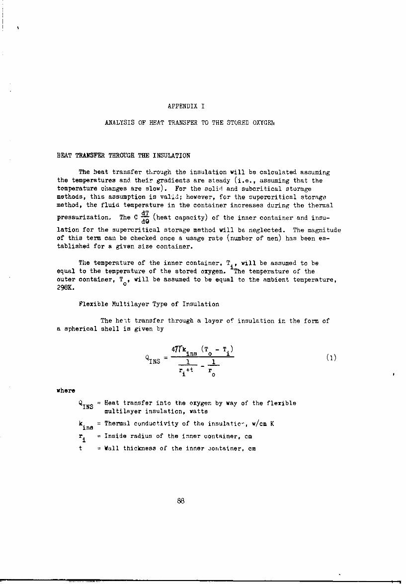
APPENDIX I
ANALYSIS OF HEAT TRANSFER TO THE STORED OXYGEh
HEAT TRANSFER THROUGH THE INSULATION
The heat transfer through the insulation will be calculated assumingthe temperatures and their gradients are steady (i.e., assuming that thetemperature changes are slow). For the solid and subcritical storagemethods, this assumption is valid; however, for the supercritical storagemethod, the fluid temperature in the container increases during the thermaldTpressurization. The C f (heat capacity) of the inner container and insu-
lation for the supercritical storage method will be neglected. The magnitudeof this term can be checked once a usage rate (number of men) has been es-tablished for a given size container.
The temperature of the inner container, T., will be assumed to beequal to the temperature of the stored oxygen. The temperature of theouter container, To, will be assumed to be equal to the ambient temperature,298K.
Flexible Multilayer Type of Insulation
The heat transfer through a layer of insulation in the form ofa spherical shell is given by
47k ins (TO - Ti)
QINS 1__ (i)ri+t ro
where
QINS = Heat transfer into the oxygen by way of the flexiblemultilayer insulation, watts
k. = Thermal conductivity of the insulatic-, w/cm Kins
ri = Inside radius of the inner container, cm
t = Wall thickness of the inner jontainer, cm
88

r = Inside radius of the outer container, cm0
Ti = Temperature of the inner container, K
T = Temperature of the outer container, K
Figure 52 shows the geometry used in defining the parameters of equation (i).
The inner container wall thickness is given by
fP r - f~irl(2)
2Sy
where
f = Safety factor
P. = Internal pressure1
S = Yield stress
for the solid 02 and subcritical 02 storage and by
t = ri 1 1 + f~S -i (3)
for the supercriticel 02 (higher pressure) storage. (see Appendix IV,Analysis of Weights for Oxygen Storage Systems).
The insulation thc'mal conductivity is a function of thetemperature on each side. The ambient temperature will be assumed to be298 K, which will also be T . The oxygen temperature (and Ti) will dependupon the method of oxygen s~orage.
Solid 0 2 : 12 K to 5.'.36 K
Subcritical 0,,: 90.1i K (i artm)
Supercritical 0,: 104.' K ý55 atm; initially 95% full
of liquid at 1 atm) initially andincreasing with time (or amount offluid remaining as shown in AppendixIv)
89

The laboratory measured thermal conductivity on flat samples is approxi-mately 0.173 x 10- 6 w/cm-K for temperatures at 77 K and 300 K.For the insulation applied to a spherical container with overlpping andpenetrations, the value is approximately twice that of the laboratory value:0.35 x 10⁻⁶ w/cm-K. Using a temperature variation for thd thermal con-ductivity given by Wang (1961), the relation to be used for this analysis is
T'+ + .OU)qTJ+TZ 112TZ +T
+(T1 9 " [0.0374 * 2 + 00 x 1O -w/cm-K (4)
For TI = 77 K and T2 = 298 4X,
T 1+ T 2IT 2 IT2100 3.75 \ + \100/ 9.475
k(77,298) = 106 (0.140'3 4 0.2097) = 0.35 x 10⁻⁶ w/cm-K
At TI T 2 298 K
T1 +T2 Tk') IT 2 1 2100 =5.96; + = ý- 17.76i4
- -6 -6/k(298,298) 10 (0.223 + 0.625) = 0.848 x 10- w/cm-K
Multiplying Equation (4) by (T - T2) gives
kAT 0.0374[(1) 100 ()0] -F
10-4 (w/cm) (5)
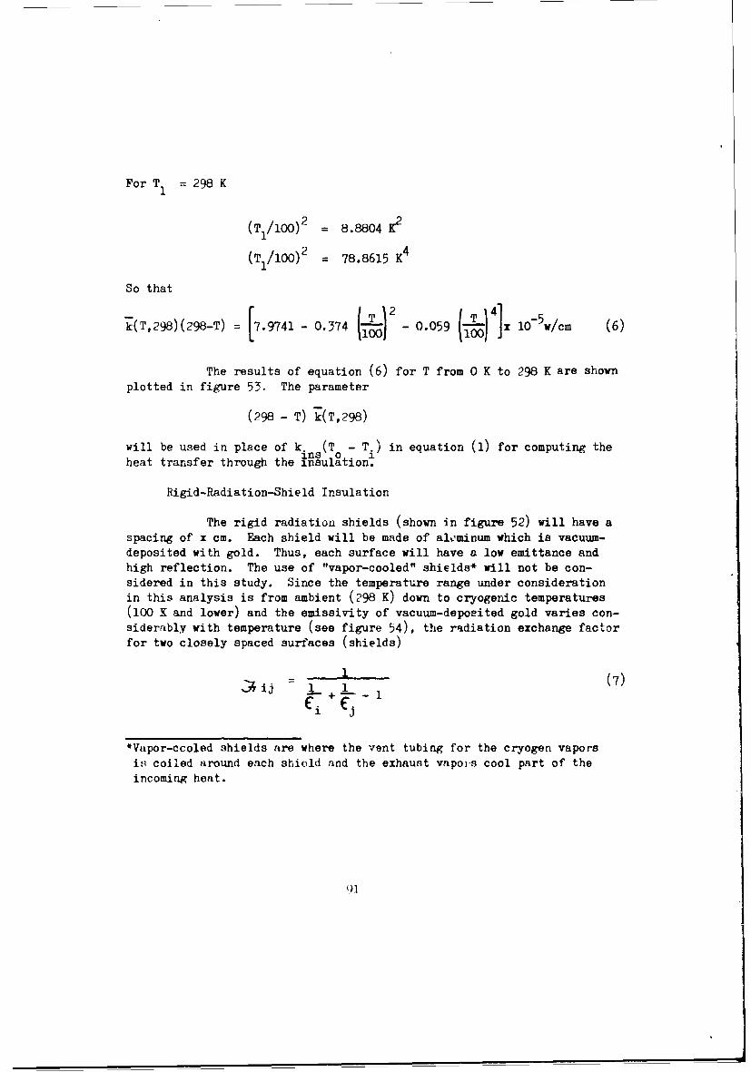
For T1 = 298 K
(T1/lOO)2 = 8.8804 K2
(T1 /100) 2 = 78.8615 K4
So that
k(T,298)(298-T) = [7.9741 - 0.374 - 0.059 1x 10⁵w/cm (6)
The results of equation (6) for T from 0 K to 298 K are shown
plotted in figure 53. The parameter
(298 - T) k(T,298)
will be used in place of k. s(T - T.) in equation (1) for computing theheat transfer through the insulation.
Rigid-Radiation-Shield Insulation
The rigid radiation shields (shown in figure 52) will have aspacing of x cm. Each shield will be made of alominum which is vacuum-deposited with gold. Thus, each surface will have a low emittance andhigh reflection. The use of "vapor-cooled" shields* will not be con-sidered in this study. Since the temperature range under considerationin this analysis is from ambient (298 K) down to cryogenic temperatures(100 K and lower) and the emissivity of vacuum-depoeited gold varies con-siderably with temperature (see figure 54), the radiation exchange factorfor two closely spaced surfaces (shields)
•1 (7), ij - 1 1(
*Vapor-ccoled shields are where the vent tubing for the cryogen vaporsis coiled around each shield and the exhaust vapors cool part of theincoming heat.

"VACUUM REQaON WITHA SECTION OF R1RADIATION SHIELD TYPEOF INSULATION
OUTER CONTAINER
Bm SUPPORTS
SHIELD NUMBERING(6 SHOWN)
CONTAINERTNA
STORED OXYGEN
\
VACUUM REGIONWITH I.•TSULATION
NOTE: SUPPORTS BETWEEN THE (FLEXIBLE MULTILAYER
TWO CON.CAINERS ARE TY PE)
NOT SHOWN
Figure 52. Cros--3ection View of Oxygen Container IllustratingInsulation Shielding Geometry
92

Eqiiation 4 1.) K(T,298) (2W8T) [7.9741 -.37 ..ON 4~) ] X 0 /,
7-
6
E5
4 -
0 100 200 300
Toswaftwo M.') K
Fiswm 53. FMSMU MufmyW ThwmW C.Ansiied Pow' 1@ K (T.9) (236-)

C4
.0
.0Q
IL
0zI 11D W
S S S )4

is not strictly valid (in this equation, C and C represent the emiesivityof surfaces i ani j respectively). However, for en4 rgy at any wavelengthA , the relation holds (see Eckert and Drake, 1959, pp. 403-404) such that
q bli- + A, (8)
A 1
where
q = Heat flux transferred from surface i to surface j perqX unit increment of wavelength, w/cm2 -_
E J j= Planck's blackbody radiation function with temperatures ofsurfaces i and J, respectively
CI1 A-5
bAi C2/AkT -1
se -i
Ai Emissivity of surface i at the wavelength A
='j Emissivity of surface j at the wavelength A•I
The total heat transfer (qT) per unit surface area is givenby summing equation (8) over all wavelengths as indicated below:
qT f qA dI.
0
or 06
f E býX - 'bXj dA (I0)
o + 10i CAJ
T'.

Multiply-ing the right side of equation (10) by CAc /C =-
gives
00 f, Ai E j -(E -F e.X (n)A~i*E ACiCA ~
0
as a general relation.
In the problem with the vacuum deposited gold shields, IIAE -Cl (C -'ý 0.02),
and IEi E' can be neglected in comparison with CAi . Also with
the gold finish, a type Hagen-Rubens equation (Dunkle, 1963) which ismodified to give the total hemispherical emissivity and fit experimentaldata of figure 54.
= kr (12a)
=kr (12b)A j r A.1where
k -= A constant, 62.8 (41) -ohm -cmr
Pi = Electrical resistivity of surface i,D = Electrical resistivity of surface j
X = Wavelength
Then substititing equations (12a) and (1b) into e.uation (11) anddefining .":
+~2L F-J 'approximato.I-L0 ,3- Cswtl A(3

and defining J and J
00
and
00
~~- d' .-5 4 -Aoo A
3 0gives
T = .i. Ebi - ij Ebj
For the approximateJX in equation (13)
±00 -k'4 o/i P f F (T X)- CI(AT,)- dA T,
0 e
r ji~O ~i j (14)
bvhere
K C (AT )- 2 J measurementr i - corrected for
o e -1 gold
For gold (and most pure metals) D3lov approximately 300 to 400 K. theel~ctrical resistivirv is linear with temperature.

) J/P in ohm-cm
TT {T in K
Tising this relation in equation (14) gives
[oKr T, T.( .T
- -T.T.T.= 0.74 - Zc
y Ti TS
Ther for both i and j
0 Po /.1~
04 [ T. J 0 . 7 4,
JT.
Note that
7. or --
Then 7T.T (- 4 (o.° -- - -I 7A , ( T 4T_ (1T"
Equation (15) can be written as
T Tj V

where Q( ... s the absorptivity of a surface at temrerature Ti of energyfrom a radating source at temperature Tj (or vice versa). Both surfaces
radiate according to the Hagen-Ruben's Equation and P = T T. UsingT0
Kirchhoff's law and equation (12a)
S= = k r
whereC j.i is the spectral variation of Cij. By definition,
o ( Aij b ij C ( j).
rd (T1T'~ •[j_½ dT
= "o e • _
or
O~i =Kr " PoTT: OV o
k ) T.
or
(X 3 KI T.T. = 0.74 0 F7
A similar analysis shows Ci = 0.74 . . Thus, whon T. =Tj
* - s-aA•fying Kirchhoff's law for equilibrium.
Severa', sources of emissivity ani absorptivity data for gold!ire plotted as a finction ef temp-erature from 0 to 300 K in figure 54. Thedata for the measured absorptance was used in equation (16) for the solutionof the shield tomperaturep and the heat transfer Iy radiation through thpshield- to the oxygel,.

ý0.21 T-1•ij (o, o2i/Ti = 0.667' 1O-4 •
Equation (16) applies to any two adjacent shields and qTmust be the same between each pair of adjacent shields. Likewise,the same must be true between either container (also assumed to begold coated) to its adjacent shield. This condition is true for theassumption of negligible heat conduction through insulation stand-offsas in the present analysis.
qi =q (17)
and equation (16) with 0( ij = 0.667-10 T.T. becomes
qi o0"667-10-4 T -Ti4 T. +5 (1)
Q A q.., Aj = 4W R, 2 (19)Qij =ji' Aj1
.thwhere Q. is the heat ... ns-7,r through the total area of the j shield, watLt
A. is the area of the j " shield, cmJ
R. is the radius of the j th shield, cmJ
and R. is gi+en by
Rj.. ri + t + jI

where
r = the inside radius of the inner container, cm
t the thickness of the inner container, cm
thj = the j shield from the inner container
x = the shield spacing, cm
Equations (17), (18),and (19) were programmed on the IBM 360digital computer for numerical solution by successive iterations on theshield temperatures with the inner container temperature equal to thestored oxygen temperature and the outer container temperature fixed atthe ambient temperature of 298 K. Once the temperatures have convergedýin th: computer program), the program compares the radiant heat transferthrough the shieldz. Solutions were run for 0, 1, 2, 3, 4, and 5 shields(N) and varying r, from 5 cm to 125 cm. The case of N - 0, iteration isnot necessary, anr the heat transfer can be calculated immediately fromequation (16) similar to the following:
In equation (16) with i = 1 and j = 2
12 1 4.5 4.51q 1 2 =;T ,~. 7.T, [T1 4 T 2
4 2Use T = 300 K, then T 0.0459 w/cm
and T2 = 777 K, then T = 0.0002 w/cm2
T IT2= 152 K
'12 0.667(10-4 T
or from data on figure 54
cx 0.0101?z•= ~l
lh)i

S~ ~~17.32 0.5
17.32 + 8.95 -26.27
;F2 8,95 8. 0.33017.32 + 8.95 26.27
q 0.0100 [0.659(0.0459) - 0.330(0.0002) = 2.93 x 1074 N/cm2
The results of this analysis, equations (15) or (16) are verysimilar to and are substantiated by work presented by Rolling and Tien(1967) and Tien and Gravalho (1967) on thermal radiation between non-graymetalic surfaces at low temperatures.
h'AT TRANSFER THROUGH THE SUPPORTS
The heat conducted to the stored oxygen through the supports betweenthe inner and outer containers is a function of the number of supports(four), cross-sectional area of the supports (Appendix IV) length of eachsupport, and the thewlal conductivity of the support material.
The support material will be a titanium alloy such as Type 4AI-4Mn.The thermal conductivity of this type of titanium is shown in fgure 55as a function temperature. The heat conducted through the four suipportsis T
AS3 /
qs 4 ASL k(T) dT (,0)T i
where L and A are the support length and cross-section area, respectively.S S
Defining the average thermal conductivity as
102

T
k(T,- T) 1 T k(T) dT (21)k0 T - T 1
T i
where k(T) is the thermal conductivity at temperature T,
q 4 (T 0 T) L (T T (22)LS iO
For all the different oxygen storagq methods, 1I will be 298 K;Ti will vary with the type of storage. 0
The support cross-section area is, from Appendix IV, equation (99),
fW a
A T (23)S S
y
where
WT = Initial total support weight (mass), grams
a = G-loading (10 to 50 -F3), G
S = Titanium yield strength, grams/cm2
f = Safety factor
The four supports shown in figure 52 are radial, high-strength,titanium alloy wires which extend from the inner cont&iner through theouter container to the corners of an imaginary tetrahedron circumscribingthe outer cc:itainer. Rigid tubes would extend the vacuum jacket from thecontainer to the end of the supports and simaltaneously act as legs for thewhole conlainvr. It was necessary to mnke the supports long in orderreduce the heat transfer to the order of mngrnitude of that through tlinsulation. However, for some missions where the oxygen usage rate iruhit'h, shorter suppo-ts and higher heat loads can be tolerated. When theoxygen ic to 'e stored for extended periods of time before usage, aminimum total heat lo:,d i:. required. For the support ccnfiguration selected,the supporto exter.d outside the outer contdiner a distance of Pr ; thus the0total ziupport length in givern by

LS = 3r - ri - t (24)
where
r = Inside radius of the outer contaiher, cm0
r. = Inside radius of the inner container, cm
t = Wall thickness of the inner container, cm
The total weight isWT =W + +25)T= W2 + WIC + WINS
where
WO2 = Stored oxygen weight, grams
WIC = Inner container weight, grams
WINS = Insulation weight, grams
For subcritical storage, the weight of the phase separator must also beincluded ir. equation (25).
The thermal conductivity and average thermal conductivity between avariable low temperature and 300_Y upper temperature are shown plottedin figure 55. The dashed curve kfT.3GO) will be used in equation (22) forcomputing +he heat conduction through the supports. For a high temperatureof 298 K
(T - 298) k(T,298) : (T - 300) k(T,300) - (300 - 298) k(298,300)
= (T - 300) k(T,300) - 0.1754
where
298
29(8,T f k(T) -T
T
1 4.1

.10 -....
.09-
.0-.07 - - - .000
-/-~ A
.06 o P-t Lr
~.05 Z/04- Wadd Tech. Rept. 60-56, A Comnpendiumn
.04 __ __ - -of the Properties at Low Ternperatures(Phan I1. Part I. Properties of
Solic•; Ti. Alloy type REM-CRU RC1308- _____ -4.7VMn. 3.99%A11- .14%C.
-0- ASD-TDR-63-741, Aerospace Structural
.03 Materials Handbook, Vol II, Non-Ferrous Alloys, March 1963, Ti Alloytype 4 A1, 4Mn (lalternate RC-1308)
300
k(T) dT -k (T,300 for the
.02-I
solid curwv
.01 _
0 50 100 150 200 2?0 300
Tomporeturm (T). K
FIsure 55. Thermal Conductivity of Titanium Alloy vs Temperature
Type 4AL 4MN

RESIDUAL-GAS HEAT CONDUCTION (in the rigid radiation shields)
The magnitude of the residual gas conduction is usually very low ina high vacuum; however, a check calculation will be made to compare with theother modes (multilayer insulation). Vance and Duke, (1962, pp. 154 - 156)present the equation for residual gas heat conduction between two surfacesin a vacuum as
W = KO(P (T2 - T) (26)gc2 1
where
W = Net energy transfer per 2unit time per unit area of innercontainer surface, w/cm
K = = 0.0159 w/cm 2-mm of Hg-K for P measurel87TMT at 300 K, N2 gas
R = Universal gas constant
M = Molecular weight of the gas
T = Temperature of the gas
7 = Ratio of specific heats, cp/cv
P = Pressure, mm of Hg
0 = Overall accommodation coefficient 1 + k'2 -?\2AI/A 2
A =Area
Subscripts 1 and 2 refer to the inner and outer surfaces,respectively.
For the present configuration -..d for no shields
AI A,
1 ,2

and from Vance and Duke (1962, p 156)
U 2 = 0.85, UY = 1.0, for T = 300 K, T - 77 K.
The temperature difference is
T2- T1 300-77= 223 K.
0=°0'85 = 0.851.0
W = 0.0159 (0.85) P (223) 3.01 P
P 9cM 1w/cm2
10-5 3.01 x 10⁻⁵
10-6 0.301 x 10⁻⁵
10- 0.0301 x 10-
Comparing the residual gas conduction with radiation where there are noshields but the inner and outer container have a low emissivity,
t 1 "2 = 0.015 (average)
77 K, , =300 K
r 4(T4 - 4)A al-

J, C2 (0.015), 0.015
-f + (1- C2) el -: 0.015 + 0.015 (0.95) - i.95
= 0.00756
T2 = 300 K, (dT24 = 0.0459 w/cm2
T1 = 77 K, 4 =0.0002 w/cm2
S(T24 - T14) = 0.0457 w/cm2
r -= 0.00756 (0.0457) x 10-5A
= 34.5 x 1075 w/cm2
at P = 10-4 mm of Hg, W is 90% of q/A
at P = 10-5 mm of Hg, W is 9% of qr/Agc
at P = 10- 6 mm of Hg, W is 0.9% of qr/A
For N shields:
Assuminb, W = h AT, A 1i = temperature differential between any twogc gc
shields are hj changes negligibly with temperature,gc
thenh
gc N 2 1
where T, - T is the overall temperature difference.e 1
Assuming that the emissivity changes are negligible with temperatureof shields, the radiant energy decreases by a factor of 1/(N * 1). Thus,both ... iant energy transfer and residual gs conduction decrease at the.,ame rate as the nut ber c' shIeldn' in ;ncrentsed.
i( .

Looking at the shields on the cold side for the case of many shields,p = 10-6 mm-Hg and KP = constant (see Scott, 1959, pp. 145 - 147), conductionb3 tha residual of gas is
[Ai = 1.0 (0.0159) (1O0) ( -- 1.o0)
Lt= 0.159 x 10⁻⁷ w/cm2 -K
The radiation between assumed shield temperatures of 77 K and 100 K with• .. , (0..0o6)c
surface properties of C1I C2 0.06,.-i_2 = 0.006 + 0.006 (0.995)
0.006 - 0.00301, is (using the linearized radiation equation):1.99%
- 4(0.00301) (5.669 x 10⁻¹²) (88)3
= 0.466 x 1-7 w/cm2 -K
Thus: Radiation is 3 tnmes the residual gas conduction at a pressure of10-6 1torr
hndiatiori is 30 tdmes the residuall gas conduction at a pressure ofi0-7 torr
For the ,'igid radi:-Ltion shield insulation, the pressure in the vacuumregion will bo':cc i.sued to be 10-7 torr and the residual gas conducti on willbe neglected.
'r..?ALHT "'"A-F•R '..' TE "TU.E; OXYEN
Tihe tot'(l hen tr-'.ofr • •-e storeo oxygen tot) iq giveon by
toto,tot • )"• ;)7
• t 0¼

for the flexible multilayer insulation. For the rigid shield insulation,the total heat transfer is giver, by
= qT + s (28)
The component heat transfer relations given in Sections I and IIand in equations (27) and (28) were programmed for solution on the IBM 360digital computer with the storage container size, insulation parametersand support parameters as variables. Results are presented in figures 56through 59.
Figures 56 and 57 present the total heat transfer (through theinsulation and supports) as a function of inner container radius for solidand liquid, respectively. Also shown in figure 56 is the heat -Cransferwith rigid radiation shields with vacuum deposited gold; the results areof the same order of magnitude as with flexible multilayer insulation. Thetotal heat transfer into supercritical oxygen as a function of inner con-tainer radius is presented in figures 58 -nd 59. Figure 58 illustrates theheat transfer tc the ojgen at its initial temperature of 104.2 K. Figure59 presents the same data when the oxygen Is at a temperature of 158 K.This latter temperature corresponds to the condition at which minimumheat transfer is required to deliver a constant flow rate, i. Thisphenomena of a reduction is heat input requirements is due primarily tothe reduction in the specific heat capacity of oxygen near the criticalpoint of the material. (See figure 60 and figure 61 of Appendix !I, HeatingRequirements for Oxygen Delivery.)
110

5. Z
rr
LA
N 0 004a,
LLz
4n24
404
00
IE-z0
AnSUAR* L V4N V 'V-J

TIs 0.5 cmn
NOTES: 11 Liquid OxYglmStorSgl
2) 63.6 G'sDaIln Loadingonso su p rt 50 a's In 3-Di fiction) t... .N1 T. Insulation Thickness
Ins IFlexible Multilawer)
1.0 cm
2.0,cm
-/_ - -
20
0 20 40 6a 90 100 120 140
Invernol Contuakr RNdm I(i)I. cm
Fipwv 67. TOW1 HM Twmsdu ThlsiOv I a.dm~i wd 5UppWU vi Inane' C bm'"w Rsdima
I11'

60... ,.T Tin 0.5 cm
NOTES: 1) Supercritical Oxygen Slorage, /Initial Storage
2) 8C.6 G DWgn Loading onSupports (50 G in 3-E1.¢ection!
3)T - ITnulatin Thicknes
40
00 20 40 S0 30 180 1 20 140
SIntu CoetawrlaIuWll IR~, I|a'n
S~Fiaus 5. Tq,ul teet Tur'ler Themsgh I smgotom au Suppm~e we IelmdCmsl,. Rails.
1'9 ,f

I I -0.5 cmNOTES: 1) Supuerirtlcal Oxy~jon Storap,
50 at Minkmum RquiralHOstng - - - - -- -
3) ~f - Irmilaton Thiknu - ___ .
(FlaIb4.~ Multilaysri
40-
1.0 cm
2.0cm
20
to
000 . 10 10 140
P .Toot. Him T wudv TheowO IMOaOOM OW 2uNpWu Ust Con10"'Ww
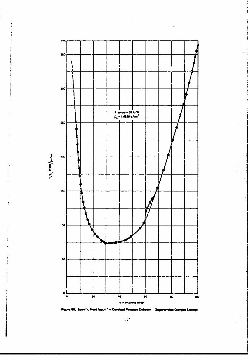
370 ~ ~
J-l-
300 --
-I----- -- 55AII - I.Om %/CM 3
260 - - - -- - -
200- - -
60 -0 /0 Io G
F"00 .owfc W ot*tCn m oweetm --uwrik -xq ln
so---1-

350 **~-- - - - r-
ILI
150 - ~
200 - -_
FW*$1 FW - -t -b- mCw P o *vy-Spwa-o -xp S
APPENDIX II
HEATING REQUIREMENTS FOR OXYGEN DELIVERY
SUPERCRITICAL OXYGEN HEATING REQUIREMENTS FOR PRESSURIZATION
The pressure in the storage container is to be held constant at55 atm. The initia] density (p0 ) is 1.0839 g/cm3 or 33.8717 g-mol/liter.This density was calculated assuming the container was initially filled.ith liquid at one atmosphere to 95% of the container volume.
The fluid heac input required for constant pressure operation in asupercritical storage vessel can be derived from the first law of thermo-dynamics. The result is given by
6h (29)
where
q = Rate of heat transfer (by any method) into the vessel, joules!see or watts
= Weight or mass flow out of the vessel, mol/sec
h = Erthalpy of the fluid in the vessel, joule/mol
P = Pressure of the fluid in the container, atm
- = Density of the fluid, g/cm or mol/cm
It is noted that the fluid density is directly proportional to the1•. density and the fraction of the initial tank contents remaining in
the vessel at any time, Thur the fluid heat input is directly proportionalto delivery rate and to a quantity which can be determined from the thermo-dynamic properticn of the fluid stored. Thin quantity, -p(b,/bp)p, is
a furzction of fluid density at given constant presaure and thus varies&urir• operation. Fluid temperature also varies durirng operation.
1,

However, since there is only one phase and pressure is held constant, onlyone other thermodynamic variable is necessary to define the procecs, i.e.,temperature or density.
The specific heating rate equation (29) was calculated numerically
from tabulated thermodynamic data givon by Stewart (1966). The resultsof equation (29) are plotted in figure 6U as a function of percent weightremaining in the container where 1
Percent Remaining Weight = 100 ITO-Figure 61 shows the fluid temperature as a function of percent
weight remaining in the container for constant pressure delivery ofsupercritical oxygen at 55 atmospheres. This curve will be used tocalculate the heat transfe: into the container.
LIQUID STORAGE WITH HEATING AND VAPOR REMOVAL
For this study the liquid will be considered to be stored at co:,stantpressure. The two phases will be considered separated in the storage venselwith only the vapor removed.
hV
- Pressure and temperature are constant.U Applying the First Law of Thermodynamics
P ,to the process,
656Q. 6 u Vh,. 6 m (30)
where
OQ H Eeat added in time 6 06 U . Change in internal Ynergy ct.4ng* ot the fluid in the veassi
h. Frthalpy of the vented vapor (in this cn.•q, ent!halpy of thesaturatol vapor at the prosaur* F)
6 a Vapor reoyved in tiao .Q

The change in internal energy ia
6U = u -U
where
U1 = Internal energy at time 9
U - Internal energy at time 9 + 60Also
6U = m2U2 - Yl
where
u = Intrnal energy per unit mass
m = Mass (liquid + vapor) in the vessel
In terms of the masses of liquid (L) and vapor (V),
SU = m2LL + '2VV ( - ( ÷ •V)
(31)
m 'L(m2L ' Id) + V('V - lv)
Performing a mass balance on phasei it-: 4 de the centainer,
"ML -, 6o , +" (,2v - IV) (32)1L 7L32
5 m IL "2L "( -v (3)
.o. saituting equAtion (32.) into eqiuatior ()I' gisrt
(34)"~ - S, * -in) ( " -11
119)

Substituting the definition of enthalpy of the liquid (hN = UL + P/OL)
into equation (34), where PL is the liquid density, gives
'UI=-6 o +6m(/p '+(m2V - lV) (V - 'd
Also
'IV -uL -hV •h L P ( -- P , (36)
and
2V - m1v Pv AVL
where
AVL is the volume of liquid evaporated
But
orAv, --L(ml, m2v)PV ( Mor
m2V- mlV pLL lL - m2L) (37)
Substituting equation (32) into equation (37) gives
"m - mv = 6 + 2V (v 2 lV)
or
PV ~ 2 El 1 PL
a nd 2V EV 6m. (38)
120

Substituting equations (38) aid (36) into equation (35) gives
or
6u= 56mh, +m Mj (VPL4V -hL)"" l& "f, (• "•')(39)
Combining equations (39) and (30) gives
6(V I-JL +6 -h. 6m h hL) PL~v)
Dividing by the time interval Q and letting
IV hL =UVL
•ive•3
(q T2 `/mV (40)where
HVL = Heat of vaporization of the liquid at the pressure P, j/g
= Vapor removal rate, g/s$ac
q Rate of heat addition, vat-as
121
I

For liquid-oxygen storage at 1 atm (1.0333 kg/em2 )
35.6471 mol/liter
V C.1396 mol/liter
=L 35.6471 0.1396-35.5075 1 + 35.5075 1.00392
HVL= 6825.8 j/mol = 2133.0 jlg
and from equation (40)
q = i(213.30) (1.00392)
q = 214.14 i (liquid storage at 1-atm absolute pressure)
= 214.14 w/g/sec (constant)
SOLID STO&AGE WITH HEATING AND VAPOR REMOVAL
The equation for heating and vapor removal of constant pressurefor liquid storage also applies tc solii storage (with solid and vapor inequilibrium below the triple point pressure) with the substitution of theheat of subliaation for che heat vaporizaticn and the solid density for theliquid density. Thus for solid storage
122

where
q = Heat addition, watts
= Mass rate of vapor removal, g/sec
= Heat of sublimation, j//g
= Density of the solid at the container pressure andtemperature, mol/liter or g/eu cm
1V = Density of the vapor at the pressure and temperaturein the container, mol/liter or g/cu cm
For solid-oxygen storage, the pressure will be less than 1.14 mm ofHg absolute where the vapor density will be negligible compared to thedensity of the solid. Then for the solid-oxygen storage, equation (41)becomes:
q Ac• (42)
For solid oxygen slightly below the triple point (T.P.) (54.36 0K and1.14 torr), the heat of sublimation is
As = 8176.0 j/lol (at T.P.)
= 255.50 j/g
and
= 255.5 watts/g/sec (at T.P.)
(19.3% greater than the liquid storage at 1 atm)
123

APPENDIX III
ANALYTIC STUDY, COMPARISON OF LIQUID VERSUS
SOLID OXYGEN STORAGE
INTRODUCTION
A comparison analysis of solid versus liquid oxygen storage lifehas been made where the solid is reduced to the liquid phase after theextended storage time. By starting with solidified oxygen, instead ofthe saturated liquid for either the subcritical or supercritical storagesystems, advantage can be taken of the sensible hoat capacity, heat offusion, and increased denaity of the solid to increase its storage life.This can be done by launching it as a solid and then allowing it to liquefyafter launch. A comoination of methods could be used to achieve maximumusage of the solidified oxygen. An example would be the case in which aportion of the solid oxygen is sublimed to space prior tn liquefacation.Instead of wasting that part of the oxygen which would be lost to space,it could be sublimed to adsorbents which would subsequently raise itspressure to a breathable level. However, when the solid is being melted,the container would be sealed.
The general procedure is to start with solid oxygen in a givenDewar where, with the increased density of the solid, a greater loadingof oxygen in the container can be realized than is possible with liquidoxygen. (Solid is 14 percent greater.) Using both the latent heat ofthe solid and the sensible heat of solid and liquid finally ending upwith a container of liquid, extended storage time can be achieved. Also,the extended storage timi can be increased by cooling the solid belowthe triple point to achieve a greater density loading of solid oxygen.(Due to solid phase changes, loadings of up to 28 percent by weightgreater than liquid can be achieved.) In addition, the cooled solid hasa greater h3at of sublimation, as well as the increased sensible heatof the cooled solid.
Three procedures were analysed which involve starting initiallywith solid oxygen and ending with liquid. The three procedures forcalculation purposes, shown schematically in figures 62 and 63, aredescribed in the following paragraphs.
124

bz
CL 0 0.-
I- E- w
in
z
o pJ
0w C
a. 0
0+2)ca,
Cyr 4H
U -JI
CID
0% W.0
I3-.
2nC -C'
0w
>411I--
(AA
0 '1
I- Z
I mo r., o L a ti1-4
f-4 CO
AcI)TJ
02W4-)
02 -r~-4 0
CCo
z. C. 0'Y 0
00GoS .43
z
w 0% C14
0 Z=N126

PROCEDURE I, FIGURE 62
The container starts 95 percent filled (by volume) with solidoxygen at the triple point (Phase I) and having a density of 1.300 g/cc.Enough solid oxygen i8 allowed to sublime (with venting) to yield asolid oxygen weight equal to the desired liquid oxygen weight (95 percentfull by volume). The solid is allowed to melt without venting to yieldl±quid at the triple point. Thirdly, the liquid pressure and tempera-ture is allowed rise without venting to one atmosphere and 90,2 K,respectively. At this point, the oxygen is stored as a liquid withventing of vapor at one atmosphere inside the container. The densityof the liquid oxygen at its normal boiling point is 1.141 g/cc.
The following paragraphs present the formulation of the storage timewhen a container is initially filled 95% full of solid oxygen and allowedto sublime until the remaining weight is equal to the equivalent of aontainer 95% full of liquid oxygen.
The remaining (solid or liquid) oxygen after storage time G(with sublimation or evaporation) is given by
W02R = W 02 - (43)
where
9 = time, days
= vapor removal rate, kg/day
W = initial weight of oxygen, kg
WOR = weight of oxygen remaining, kg2
The vapor removal will be gover:.,A by the total heat leak, Qtt intothe container. For both solid and liquid storage,
q AK (44)
127
a

where
q = the heating rate necessary to yield a vapor removalrate of i (kg/day), watts
K = a constant, though different for solid and liquid,
K = 2.4785 watts/kg/day for liquid storage at the normalboiling point and K = 2.9618 watts/kg/day for solidstorage at the triple point,
With q = tot (45)
ThetW 0 R (46a)Th O2R= 30 K -
II t °--O (46b)
In general, the information desired is the storage time, ,for W of the solid to be equal to the initial weight of liquia which
0O2Rwould fill 95% of the original container.
KS
0 K (w W days (47)Qtots 0 WO2L
Also, the time for the remaining solid to melt, 0m, ism
qm = WORIf (48)
where H = the heat of fusion at the triple point, watt/hr/lg,(Hf = 3.660 watt-hr/kg for oxygen)
q = the average heat leak melting the solid, wýti,.
Since the temperature is constant during *he melting,
Qtotse49
where Qtots = the total heat transfer into the solid oxygen.
Then W2R (386)
0 = .(4 days (50)S (24) ots
or whenWR = WO
9 0.161 0 days (51)m Q tots
At this point, the stored oxygen has been raised to the liquidstate at the triple point (pressure of 1.14 torr and temperature of54.36 K), by sealing the container and letting the heat transfer intothe container melt the solid oxygen. Additional storage time can berealized by letting heat be absorbed by the liquid (maintaining asealed container) and raising the pressure and temperature of theliquid. The sensible heat absorbed in changing the saturated liquidat the triple point to a saturated liquid at the normal boiling pointis 16.332 watts-hr/kg for oxygen.
The time for this sensible heat change, 0L (days), neglectingthe small hiat capacity of the contai:ir and part oA the insulation,is given by
"24 0L' (52)
where i is the average heat leak into the liquid. Since the temperaturechanges from 54.36 K to 90.18 K in the sensible heat change, the heatleak will vary from Q t for the so.Ld to Q . for the liquid. How-ever, neglecting the stall change in thermal SoAductivity of the insula-tion and supports with temperature,
L 2 (tots + Qtotl
129
I

and the heat leak is proportional to the ambient to oxygen temperaturedrop, or
2 98-TL
totl = tots 2 9 8-TS
where
T = liquid oxygen temperature, KL
TS = solid oxygen temperature, K
For this case, TL = 90.18 K and TS = 54.36 K and
Q Q 207.821 = 0.854 Q
totiti 243.64) tots
Then
- 1. 1.854" = 0.927 Qtots
and from equation (52)
016.332 0O2L
L 0.927(24) Qtot
o r , = 0. 73,.5 W0 (d ays,, ) ( 54 )LQtots
The total time is QT 0 S 0 m + 0 L Combining equations (47),(51), and (5-4) gives
K K
0T Q 2! Q 0 L Q 'f0,{I 'J')f
tots 02s tots o 2
2 tot

For K = 2.962 watts/kg/day and W0 2S = 1.1395 W0 L2 2
(ratio of densities)
OT 1.310 (55b)% = .31oLqtots]
The derivation of equation (55b) is for t- condition W0 = WO2L
2 2
a function of the container radius. Qtots is a function of ri and tins'
the insulation thickness. The results of equation (55b), using computergenerated data, are plotted in figures 26 and 27 (,f the report.
Figure 26 presents the total storage life as a function of innercontainer radius when insulated with flexible multilayer insulation.Figure 27 presents similar data when rigid radiation shields are usedfor insulation. This storage life is based upon starting with thecontainer 95% full of solid and allowing sublimation until the amountof solid is enough such that, vnen melted, it fills the container to95% full of liquid. Of this storage time, apjroximately 34% is accountedfor by sublimation and 66% by melting of the solid oxygen and changingthe sensible heat of the liquid to form liquid at one atmosphere ofpressure. During the sublimation portion, venting would be required,ani during the melting portion, no venting would b- required.
The time to vaporize the remaining lquid oxygen is given by
QV 2.4785 WOL/Q (days) (36)
0 totl2
where Q = the total heat tra-.fer into the container, watts (liquidSoxygen 90.18 K ana the supports designed for solid oxygen,
95% fu~ll),
V 0OL the initial woia'ft of liquid ozygen, kg.
t5 1
!

Figures 30 through 37 of the report show the relative weight ofoxygen as a function of time for this procedure of extending thestorage time of oxygen as curve number "2". Curve number "1" is fora container which is designed for initially 95% full of liquid oxygen.
PROCEDURE II, FIGURE 63
The container starts 95% filled (by volume) with solid oxygen at43.79 K (Phase II) having a 4ensity of 1.397 g/cc. Enough solid oxygenis allowed to sublime (with venting) to yield a solid oxygen weightequal to the desired liquid oxygen wei;ht (95% full by volume). Theremaining solid is allowed to warm up without venting to the triplopoint temperature and pressure. At this point, the procedure is thesame as in Procedure 1, with the melting solid and sensible heat change
of the liquid.
There is initially 1.397/1.300 = 1.075 times the initial weightof solid oxygen as in 1?rocedure I, and there is an increased heat ofsublimation also, K = 3.300 watt-day/kilogram (w-day/kg). The weightis
S= 1.22502S 1.141 02L WOL2 2 2
Equation (47) for this procedure becomes
0 = (1.225 - 1.000) (o3oo) WO .2/Q
giving
I 1 OS = 0.7420 W02L/QII (57)
where QI is the heat transfer experienced on path II.
From state 0 to @in figure 63, the heat capacity of the soiid
from figure 3 of the report is
AEIII 117.60 + 11.05(10.563) = 294.32 cal/mol
= 0.4453 w-day/kg
132

The time for the temperature rise in the solid oxygen is
L
n = 0.4453 (58)IIII
where Q is the average heat transfer into the solid along path III
(figure 3) whore the solid oxygen temperature changes from 43.78 K to54-36 K.
The remaining state changes are the same as for Procedure I.
State@ to@
GV = 0.1608 Q-2 (59)IV
and for state to
WO2
= 0.6805 2 (60)
where Q and are the heat transfer experienced on paths IV end V,respectively.
Computer results for QT', QITI' Q.V, and QV, equal to the totalheat transfer for the terperaure experleuced at the state points shownon figure 63, were used to compute GII through QV. The total time isplotted on figures 28 and 29 of the report as a function of containerradius and insulation thickness. Approximately 1.85 times the extendedstorage time is achieved by Procedure II as by Procedure I.
Figures 30 throujh 37 of the report show the relative weight of
oxygen as a function of time for Prcoedure II as curve number "3".
PROCEDURE III, FIGUP 63
Procedure III is the same as Procedure II except that the 95%full container at 43.78 K is cooled to 12 K initially to gain the extraseusible heat of the solid from 12 K to 43.79 K.
133

'
The added storage time, @_, to be added to the time for ProcedureII, is the time for the solid to rise in temperature from state 0(12 K) to stateD (43.78 K). The heat capacity from figure 3 of thereport is
E = 22.42 + 8.05(19.914) + 2.76 (11.886)
- 215.53 cal/mod = 0.3261 w-day/kg
The added storage time is
@ = 0.3261 WO /Q = 1.225 (0.3261) W L/QI = 0.3995 W /QOS 1 2 0L 1 (61)2 2 2
@ extends the total storage of Procedure II by approximately 16%.Figures 30 through 37 of tho report show the relative weight of oxygenas a function of time for Procedure III as curve "4".
SUPERCRITICAL STORAGE
The container is initially filled to 95% full of liquid; hence,the initial weight of supercritical fluid is the same as for the liquid.The time for the liquid (sqaled container) to reach the superc-iticalstate at 55 atmospheres is governed by the mass of oxygen and the changein internal energy of the two states, A ES From Stewart (1966).
Sc.
AEs S= -3574.3 - (-4280.4) = 706.1 J/mol = 0.2554 w-day/kg
The time to reach 55 atmospheres isWOL
S = C. 25 5 4 -0 (62)SC QSc
Where Q C is the average heat transfer for the oxygen at 90.18 K and104.2 i, watts.
At thiL point, the aupercriticai fluid container would begin tovent (by pre-•ure 1,iaV^) Hoever, the vent rate varies ...........
because of the ristw in oxygen temperature (figure 61 of Appendix II),and because of the variation of the specific heat capacity (figure 60of Appendix II). The calculation is as follovs:

I
The mces flow of supercritical fluid isQ Qtot(R)
Q (R) (63)
where
R = the fraction remaining in the contairer, or relativeweight of oxygen in the container
Ksc(R) = the specific heat capacity given in figure 60, w-sec/gram
Qtot(R) the total heat transfr:- to the oxygen which is a functionof temperature which varies with R as given in figure 61, watts
Dividing equation (63) by WO2L gives
SQ~tot(R
r WL - W o2~s(R) (64)0 O 02LKSC
where
S= the "reduced" mass flow rate, g/secr
WO0L = the initial weight of oxygen, grams.
The Qtot variation with temperature is obtained from the IBM
360 computer heat-transfer program. Values for i are computed then asa function of R, using equation (64). The variatfon of R with ti.me (Q)
is given by a numerical integration of the reciprocal of z with respectto R a- follows r
RR r (i R 055)
1.0
135
i
or numerically by
r (66)
where • is the average i over the interval of AR.r r
The relative mass variation for a supercritical fluid was generated
for two cases, shown in figures 30 and 31 as curve number "5". The curves
steady out at 6.7% (0.067) because the heat transfsr goes to zero when theoxygen temperature reaches the ambient temperature (figure 61 of Appendix II).
136

APPENDIX IV
ANALYSIS OF WEIGHTS FOR OXYGEN STORAGE SYSTEMS
The weights of the various components which make up the supar-critical, subscritical (liquid), and solid oxygen storage systems,aro calculated as described herein.
STORED OXYGEN
Refer to figure 04.
Subcritical (Liquid)
W PLVYI (67)LO 2
where:
W Weight of liquid oxygen, gmLO
2
PL = Density of liquid oxygen, gm/cm 3
V = Container volume, cm 3
K = Fill factor, 0.95
for a spherical container, the contained volume is
V Tr r 3 (66)3
where:
r inside radiul- of the inner container
Then:4 3
r (69)LO "L'
137

outer Container Spot
C Vacuum RegionWith Insulation
Figure 64. Oxyge~nContaierw

Supercritical
Wsco Psc V (70)2
where
W Weight of superoritical oxygen, gm
SC = Density of supercritical oxygen, gm/cm3
K = Fill factor is included in the density
Then
W = A77 r 3 P (71)WSCO 2 3=2
from equations (68) and (70).
Initially, the Dewar will be filled with saturated liquidoxygen at one atmosphere to 95% of capacity. The pressure will beallowed to rise to 55 atmospheres with no bleed off (consLant volumeand mass). Then
Isc = 0.95 PL + 0.05 (72)
where
= Density of saturated licuid at one atm,L= Density of saturated vapor at one atm.rV
= 1.1407 gm/cm3
L3
= 0.0045 gm/cm3
Then
SC "95(I'1407" . OOA'• = ],149 - 0.01 (1.140? - 0,(,45)
1.0839 gm/cm3
piaticllythez!= n2theiiq-.Aý' wit)i the fill frictor.
S~150

Solid
w = PsV (73)WSO, )S (
where
WO = Weight of solid oxygen, gmWSO 2
D= Density of solid oxygen, gm/cm3
'S
Then:
From equations (68) and (73)
• ri 3 OS K (74)WSO 2 3 S
Figure 65 presents the freight of contajined oxygen as a functionsof inner container radius (ri) for solid, liquid, and *9upercritical storageof oxygen.
INNER CONTAINER
The inner contaJner will always be subjected to an internal pressurebecause of the vacuum jacket for the insulation. Thus, the internalpressure, Pi, will be the maximum absolute pressure experienced by theinner container for each storage mode considcred. The container con-figuration will be a 3phere.
Subcritical
The maximum pressure will be one atmosphere absolute P =
1.0333 kK/cm2 . A safety factor of 1.67 will be applied to the yield stress.The container material will be Inconel 718, which has a density of 8.20 g/cmand a yield stress of 1.23 x lO4 kg/cm2 .
The wall thickness for the spherical container, which isunder a "low" internal burst pressure, is given by the relation:
t = fPiri/ 2 s (75'
140
Q)a
caa
INi1Iwi
I- i I
0.' . f 0 .0 m r o p"o s 0k t f
U831,M) ~~ I-o wnI w1, 4'
for a "thin-wail" container (t/ri<< 1), where:
t = Wall thickness, cm
P = The maximum design pressure, kg/c m2
ri = Inside radius of the inner container, cm
S = Yield stress of the container materi~l, kg/cm2
f = Safety factor, dimensionless
For the c material given above, equation (75) gives t/r = 0.70 x 10-.
The weight of the spherical container is given by therelation:
WI..IL(r + t) 3- 3ICL 3 1 m ( + ri
=4*f rm r2t 1 + ri + t ) 2
With t/r = 0.70 x 10⁻⁴ , the last two terms are negligible and innercontainer weight becomes:
WICL = 47 7ri2t p (76)
where
WICL The weight of the inner container, gm
A--P = The inner container material, density, gm/cu 3
Combing equations (75) and (76) gives
fP -: 3V 27-r- r (7ICL
,�6
4'.
II j 'a
*1 - �t)II I I'' .1I I *
I hiK ]
-. I*1
I '.. ;
- t A
p.
A
A . 'A 4�
-. ,�'1,' . -J
S -1I A Al
I 4
i bI I -A
I w
I

II
44
AIM *
JvV

I
am m.~
/1144t4.
/ •4
\ • N

'5,
i
-i
Si - - ' a t
I'
S a
* 4JIS
A
-C
s
V
- -
t
p
F .
')Sv
1-

-tf -I
4k A
7 I
I Jill

Supercritical
The maximum pressure will be 55 atmospheres absolute,
Pi =56.83 kg/cm2 . A safity factor of 1.67 will be applied to the yieldstress. The container material will be Inconel 718, which has a densityof 8.20 g/cm3 and a yielV' stress of 1.23 x 10⁴ kg/cm2 .
The wall thickness for the spherical container, which is
under a "moderate" internal burst pressures, is given by the relation
t = r 1 + -•-1- (78)
where the symbols have all previously been defined. With the containerdefined in the first paragraph, t/r = 0.00385 and P f/S = 0.00771.
The weight of the spherical container is given by therelation 477 (ri t)•3 rl 379
WICSC 3 f - .r i + m(9
where
W = The weight of the inner container with theICSC supercritical oxygen, gm
Combining equations (78) and (79) gives. • - 3 .f 3 1 1 2
W frj 3 (1 + -- ) - 1 (80)ICSC 3 ii S
Pif ,/ P-f P'i fSince -S-<< 1, then v+ = 1 + 2-I and equation (80) becomes
"* r Pif 3W ICSC 2 S71 s + 3S r, (81)
W i21I 1+-
14
t

Solid
Solid Continuously
With solid oxygen storage, the maximum internalpressure experienced by the inner container will be one atmosphere. Thus,the inner container weight for the continuous solid 0 storage will be thesame as for the subcritical storage, i.e., equation (07) becomes
W = 2 s r7r (82)
where
W = The weight for the inner container for storingsolid 02 continuously, gm
Solid Initially. Transformed to a Subcritical Liquid
With the 02 initially stored as a solid and thentransformed to the subcriticai liquid state with a pressure no greaterthan one atmosphere, the inner container weight will be given by equation(77).
Solid Initial!_y. Transformed to a Supercritical Fluid
With the 02 initially stored as a solid and thentransformed to a supercritical state with a pressure of approximately 55atmospheres, the inner container weight will be given by equation (81),assuming that the pressure in the container is much less than the yieldstress of the container material.
INSULATION
Two types of iirqulation, flexible multilayer arid multiple radiationshields (rigid), will be considered. A vacuum environment will be re-quired for both types of insulation.
fultilayered Shields
:nis insulation consists of alternate layers of aluminirzedmylar and a thin spacer material. The density is approximately O.(•33gu/cm3 for 80 shields (mylar and spacer) per inch.
1144

The volume of the flexible multilayer insulation, independent
of the stored method, ie given by
V 7r [ro3(r + t)' (83)VINS- 3"(r
and the weight of the insulation is given by
W = n r -(- + t)31 (84)INS 3 !"ins
where3
VINS = The insulation volume, cm
WINS = The insulation weight, gm
r = The inside radius of the outer container, cm0
= The density of the insulation material, g/cm3-ins
Rigid Multiple Radiation Shields
The weight of this type of insulation depends primarily uponthe radius and thickness. When there is more than one shield, the tc ' -weight of the insulation depends upon the number of shields and theirspacing.
Ch = Density of the shield material, gm/cm3
X = Shield spacing, cm
6 = Shield thickness, cm
Ajsh = Area of the jth shield, cm2
t = inner container thickness, cm
L45

If it is assumed that 6<<5x, the volumes and weight are, respectively,
S~N
Vh = 6 Ajh (85)sh j= h
N
Wsh =Ls~h 6 Ash (86)
For one shield
Alsh = 4 IRT 2
where R is the "mean" radius of the shield; then
Alsh = 47(ri + t + X)2
For two shields
A2sh = Alsh + 47r(ri + t + 2x) 2
= 4 7r[(r. + t + xt)2 + (ri + t + 2x)2]
Then for N shields
N
ANh = Ajsh
As = 4 F 4 (ri + t + x) 2 + (ri + t ý 2X) + (ri + t + 3x))
+ (ri + t + Nx)2]

r 24 r •N(r + t) + 2x(r + t) (I + 2 + 3 + ... + N)
+ x2)l + 4 + 9 + ... + N2)2
or finallyA2s 4(11r + )+ 1) +2 N 2]
A = 4 TN(r + t) + 2x(ri + t) (N) N (87)j=l
N
The term 2 2 can be expanded thuslyj =
N2 2 2 2 2 2
1 j = +2 + 3 + ... + N = 1+ 4 + 9 + ... +ji
N (N + i) (2N + 1)
Substituting this into equation (87) gives
ANsh = 4TrN (ri + t) 2 + x (r + t) (N + l) + l 2 (N + 1) (2N + 1) (88)
Substituting equation (88) into equation (86) gives
W 47-N5P7 r + 2 +x(r. +t) (N I) x2(N I) (2N + 1)(89)sh Sn- 1 2 6 Nl ~2(~) \ J
The outer container is considered a p&rt of the insulationsince its sole purpose is to provide the vacuum region for the insulation.However, it is treated as a separate entity in the next section.
Several small holes would be provided in each shield toallow trapped air to be removed during vacuum pumping. The weight ofthe "holes" is aissumed to be approximately balanced ly small plastic(nylon, teflon, dacron, etc.) shield supports between each shield.

OUTER CONTAINER
The outer container will be subjected to an external collapsingpressure because of the vacuum region with the insulation. The weightof the outer container depends upon the radius (ro), the externalpressure, and. the containcý. material and its strength. The outercontainer weight does not depend upon the method of oxygen storage or thesize of the internal hardware. The outer container configuration willbe spherical for this study.
The maximum external pressure tending to collapse the outer con-tainer will be one atmosphere, P0 = 1.0333 kg/cm2 . A safety factor of1.67 will be applied to the computed wall thickness. The containermaterial will be:
Material: Aluminum - 6061-T6
Density! 2.76 g/cm3
Yield Stress: 2.810 x 10³ kg/cm2
E = 7.03 x 10⁵ kg/cm2
V 0.33 (Poisson's ratio)
Assuming that the spherical shell is thin, the weight is given by
, = 0 (4ffro2 )C (90)oC
where
C = Thickness of outer container wall, cm
Pmo = Dqnsity of the outer container material, g/cm3
The compressive stress in a thin spherical shell under a uniformexternal pressure in
PrS - (91),2C
i4P

However, the critical stress at which buckling would occur is givenby (see Timoshenko and Gere (1962))
S = . 2 ý92)
where
E = Modulus of elasticity, g/cm2
2= Poisson's ratio
Applying a safety factor, f, to the wall thickness after equatingS to S in equation (91) gives
Pr0 0EC2C -
c = fr -0 (z-121 (93)
0 2E
Combining equations (93) and (90) gives 1
V 4 Tf P[o 3(1 - ý r (94)
The radius r is related to the inner container and insulation dimensionsby r. = ri + t + (N + 1) x for shields, and
ro = ri + t + tins .or multilayer insulation in which
t -n insulation thickness. All other terms have been previously defined.ins
14o

INNER CONTAINER SUPPORTS
The weight or size of the inner ccntainer supports depend upon themass being supported and the acceleration (G's - shock or acceleration)and the streng'th of thI support material. Titanium alloy having a yieldstrength of 9150 kg/cm will be used as the support material for all thestcrage applications. A safety factor of 1.67 will be applied to thecalculated support cross-section area.
The dyiiamic lcad on the inner container will be varied from 10to 50 G's (in three directions). This dynamic load is the result ofall launch loading (including shock, vibration, acceleration, and anyamplification through the sunports due to the "s-riJig-mass" action).
The mass supported includes
1. Stored oxygen
2. Inner container
3. Insulation
4. Phase separator (for the liqui1 only)
but does :not include the outer container. The total weight is:
WT = W0P + WIC + WINS
where
WT = Total weight, gm
W0 = Stored oxygen weight (any method), gm
WIC = Inner container weight (any method), em
WINS = Insulation weight (either insulation), gm
For the subcritieýl liquid storage, the weight of the phase separator
mubt also be included in equation (95).
15o
I
The •1upport system will be as shown in figure 64. Each supportis being radial, the support length is given by
LS = ro - ri - t (96)
i.e., each support extends from the inner container to the outercontainer. There are fcur supports located such that the ends formthe four corners of a tetrahedron. Any one support can take the fullload. Assuming that the loads will range from 10 to 50 G in threedirections, the "full" load could vary from a minimum of 10 G to a
maximum of 50'-3G (50 G in 3 - 86.6 G directions simultaneously).
Assuming the dynamic loading to be a (G), the maximum force inany support will be
F = WTa (980) (97)
where
F = force in a support, dynes
a = G-londing, G
980 = acceleration of one-G, cm/sec 2
The stress in the support is given by
F W a(980)T (98)-s sc
where
S = The stress (tersion), gram/cmt s
2A = The support cross-sectional area, cm
s
gc = The conversion factoi- of dynes to grams force,980 gm-c/gmlf-sec'
151
The yield stress will be designated by Sy, and with the safety factor,f, the support stress must be such that
fS 5 S
s y
Using the "equal" relation, then
S W Ta
f As
Solving for A gives5
fYaA s= T(99)
y
With L as the support length, then the volume is5
V = ALB 858
The weight of four supports is
w=4pL~ [%] (io
As shc-nm in Appendix I, Analysis of Heat Transfer to the StoredOxygen, the support longth will be calculated by:
L = 3r -r - t
With
S = 9150 kg/cm2
P = 4.52 gm/cm3
S
a = 86.6G
L = 200 cm maximum
152

.T - 4(86.6)(1.67)(4.52)(200)/(9150 x 101)W T
= 0.064 = 6.4%
Or thus, the support weight is only a small part of the total weight.However, equation (99) will be used in calculating the support heatleak in Appendix I.
153

APPENDIX V
ANALYSIS OF OXYGEN USAGE
For this study, oxygen usage will be by three methods
& Crew breathing
. Space cabin leakage
• Extra-vehicular activities; dir lock operation
CREW BREATHING
The oxygen usage rate for crew breathing has been set for thisstudy at 1.13 kg/day/man. When M is the number of men in the crew,the combined oxygen breathing rate (WB) can be expressed as follows:
'B
*B = 1.13M (kg/day) (i01)
SPACE CABIN LEAKAGEThe space cabin leakage rate (L ) will be varie• frcm 0 to 1. kg/day.
EXTRA-VEHICULAR ACTIVITIES
For this study, a 1.5 m3 air lock will be opened once per day for
0 to 100% of the mission days. A cabin oxygen paruia'. pressure (ortotal pressure when no diluent is used) of 150 to 25o torr will be
considered.
With the space cabin at 298 K, the (.ygen densities for the 2cabin pressures are
P = 150 torr = 0.19737 atm; P = 0.003073 mol/literc PC= 0.0002583 g/cm3
P = 250 torr = 0.32895 atm; P = 0.013456 mol/literc c
= 0,0004306 g/cm3
154

where
P = Cabin oxygen pressure, torrC
,C = Cabin oxygen density, g/cm3
The mass of oxygen lost with each air-lock operation is
AL(l) = c(1.5) • 10 (102)
where WAL(l) is the mass of oxygen lost for one air-lock operation.
Since the air lock is ured only once per day, WAL is also the oxygen
loss per day of use. Letting F be the air lock use fraction (0 to 1.0)u
of the total mission days (duration), the total oxygen loss from the
air-lock operation is
W = 1.5 DL-l (kg) (103)AL L
where
DL = Mission length, days
WAL = Total oxygen loss from the air-lock operation, kg
TOTAL OXYGEN USAGE
When there is no oxygen "dumped" to space the total oxygen usedin the whole mission is
Wo0u= DL [l.13M + Le + 1.5 F PC-1031 (kg) (104)
and
WuL 1.13M + L + 1. F .3(105)
e 1 5
155

The total oxygen usage rate is
lO"u = 1.13M + L + 1.5 u 10(i06)
Figures 66 and 67 present the oxygen usage rate, W0 2u, equation2 L
(106), as a function of the number of men, leakage rate, and air-lockusage factor for chamber oxygen pressures of 150 and 250 torr,respectively.
156
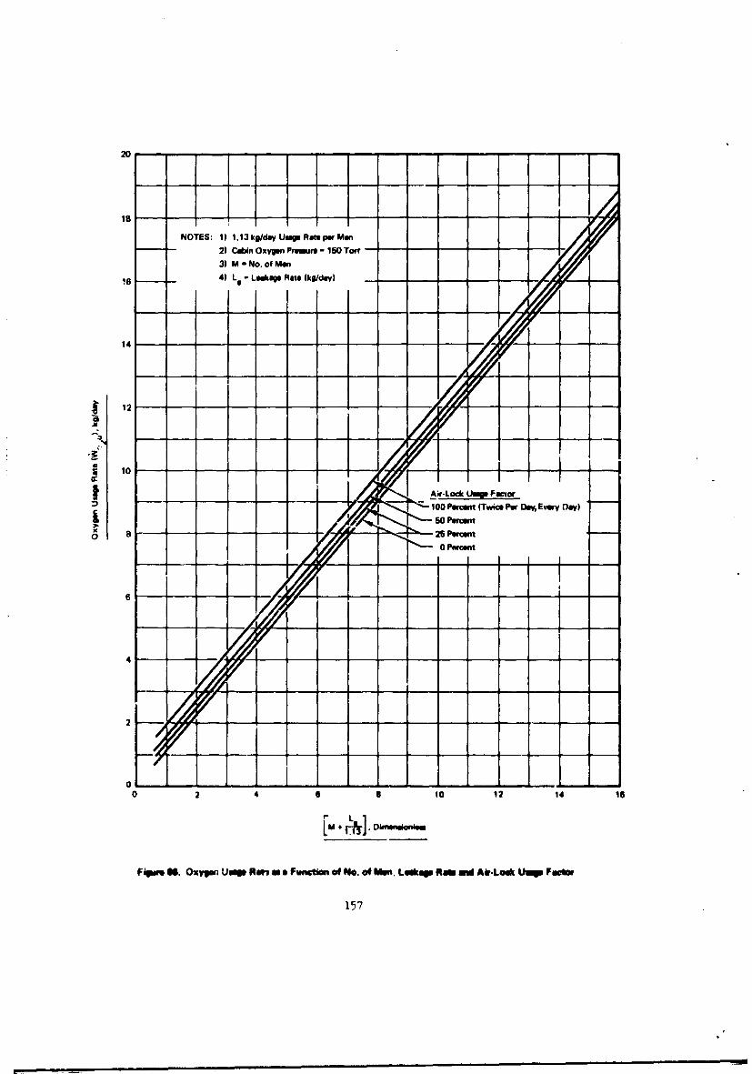
20 , ,
NOTES: 1) 1.13kg/dyUmRonperMm I n
2) Cabin Oxyge P, r - ISO Tort -3) M No. of Man
16 4) Le Lkge Rate (kg/da) -
14
12 ----
105
1 Pao tn 0re r O y Day)50Percnt
___ 26 Percent
0 Per cent
6 -- -
- - - - - - - - - - - - - - - - - - - -0 12 14 16
Flipwo 66. Oxypn Uuqm No"a ma Fu ictio of No. of Men, 1mu Ra mW AirLook Limp Fm
157
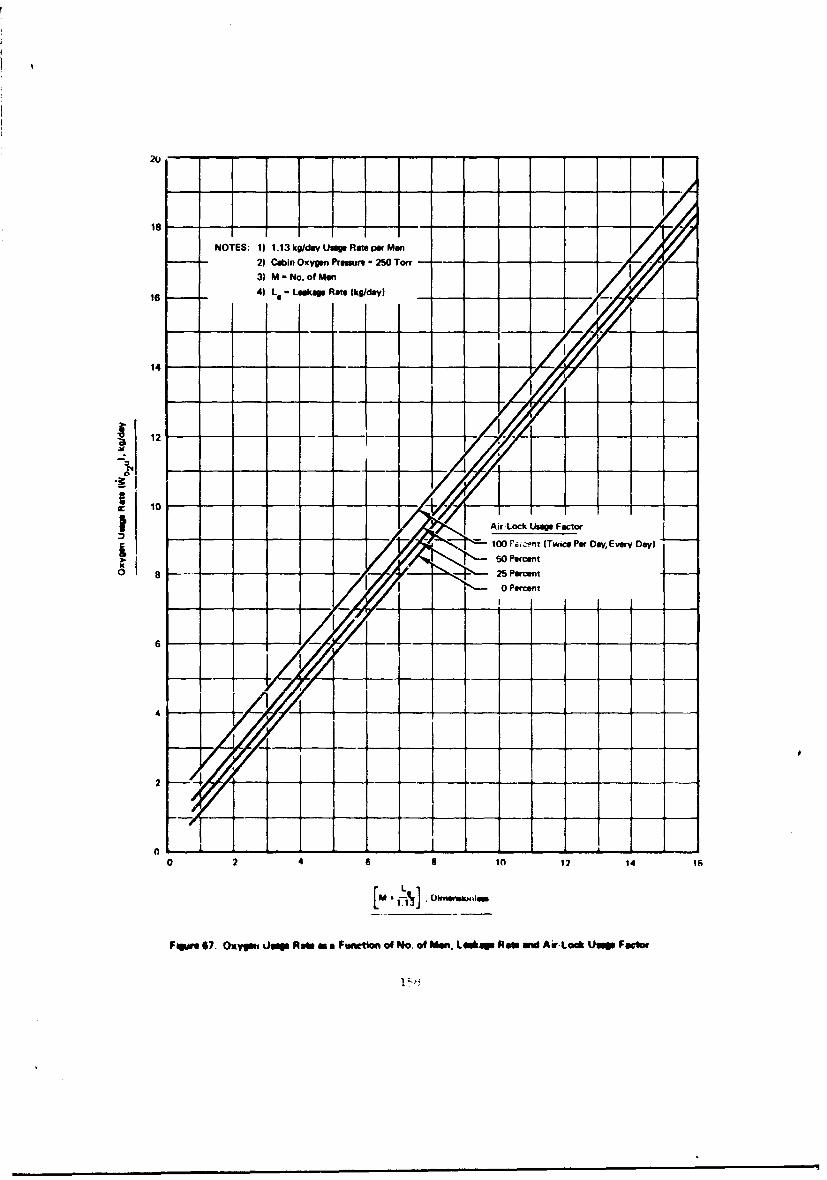
NOTES: 1) 1.13 koldayUsageRate perMan
2) CabinOxygmn Pressure - 250Torr --
3) M' No.of Men
I6 4) Le Leakage Rate (kg/day) _-
14 - - - - - - - - - -
10
------- Air-Lock Usage Factor- 100 ra.cnt (Twice Per Vva, Every Day)
0 8 25- - r-SPercent0 Percenit
0 0
0 2 468in 12 14
[M I-
Fisawe 67. Oxyut imp Raw an a Fwtimnto of No. of Man. LeekP Raw ura Air-Lock Usp Foci,~
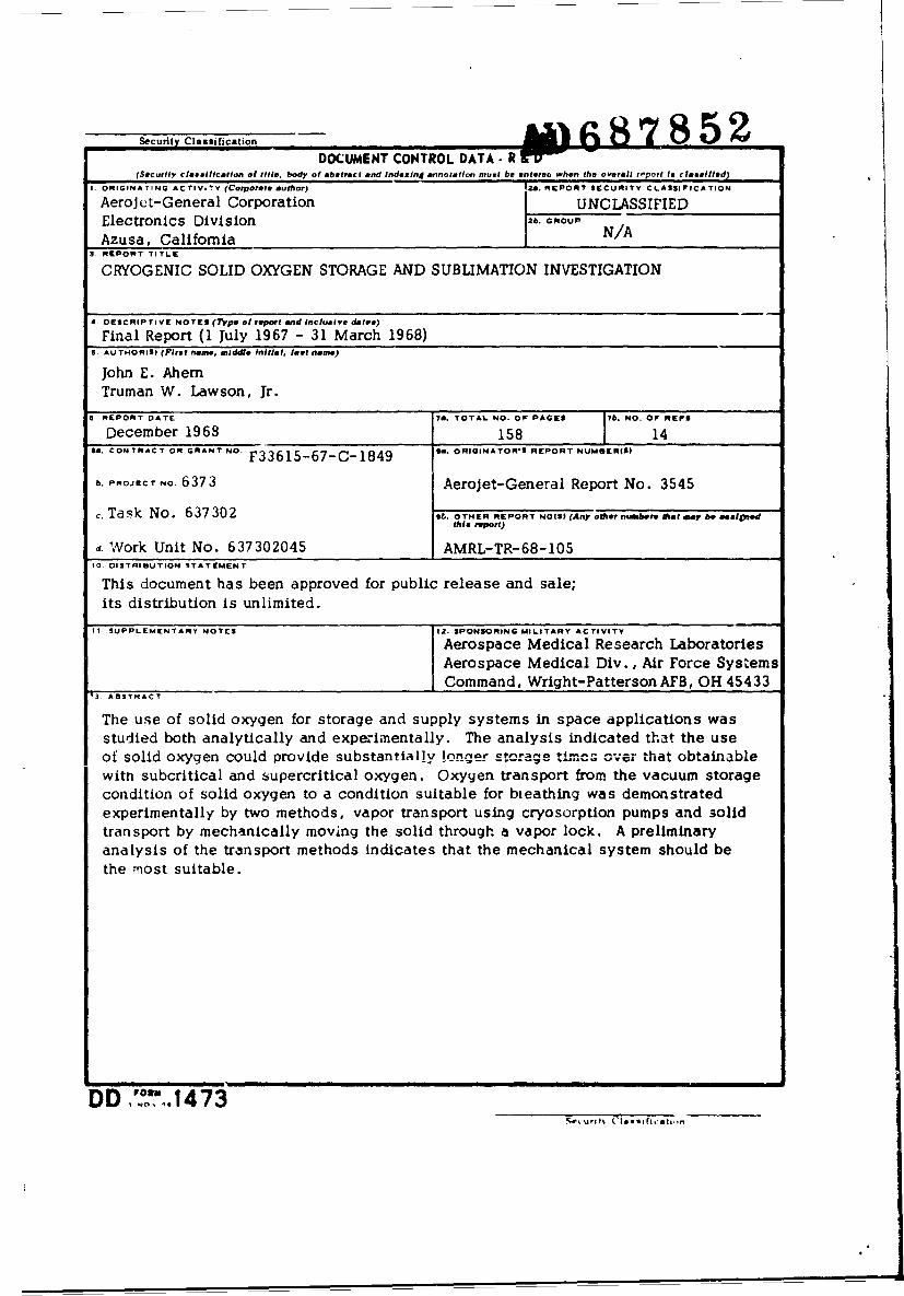
SeurtyClssfiaton DOCUMENT CONTROL.DT R h 6 8 7 8 5 92(Security classification of title, body of abstract and indexing annotation must be enterea when the overall report to classifled)
I. ORIGINA TING ACTIVoTY (Corporate author) |2a. REPORT SECURITY CLASSIFICATION
AeroJ ct-General Corporation UNCLASSIFIEDElectronics Division 2b. GROUP
Azusa, California N/A3 REPORT TITLE
CRYOGENIC SOLID OXYGEN STORAGE AND SUBLIMATION INVESTIGATION
4. DESCRIPTIVE NOTES (7ype of report and inclusive dates)
Final Report (1 July 1967 - 31 March 1968)S. AU THORIS) (First name, middle initial, last name)
John E. AhemTruman W. Lawson, Jr.
6 REPORT DATE Ia. TOTAL NO. OF PAGES 7b. o. O FEs
December 1968 1581 1.CONTRACT OR GRANTNO. F33615-67-C-1849 96. ORIGINATOR'S REPORT NUMSER(S
b. PROJECT No. 6373 Aerojet-General Report No. 3545
c. Task No. 637302 96. OTHER REPORT NO(S) (Any ot tnu.bor, that doay be aesiotedthis report
d. Work Unit No. 637302045 AMRL-TR-68-105I0. DISTRIBUTION STATEMENT
This document has been approved for public release and sale;its distribution is unlimited.
I. SUPPLEMENTARY NOTES 2IS. SPONSORING MILITARY ACTIVITY
I Aerospace Medical Research Laboratories_ Aerospace Medical Div., Air Force Systems_ Command, Wright-Patterson AFB, OH 45433
t3. ABSTRACT
The use of solid oxygen for storage and supply systems in space applications wasstudied both analytically and experimentally. The analysis indicated that the useof solid oxygen could provide substantialiy !one-tar ctorage tlncs over *that obtainablewith subcritical and supercritical oxygen. Oxygen transport from the vacuum storagecondition of solid oxygen to a condition suitable for bteathing was demonstratedexperimentally by two methods, vapor transport using cryosorption pumps and 3olidtransport by mechanically moving the solid through a vapor lock. A preliminaryanalysis of the transport methods indicates that the mechanical system should bethe most suitable.
DD "0o 61473
I.LINK A LINK a LINK CKEY WORDS - - I-4'ROLIE WT 70OLC IWY ROLE WT
Atmosphere regenerationfCryogenic solid oxygenOxygen SupplyOxygen storageSpace systems
I 2~n0SirnWMWEIýtstffcnm~rIUUUU~.EI..m,..