kuka.ethernet rsi xml 1.1
TRANSCRIPT
Issued: 10.12.20
Issued: 10.12.2007 Version: KST Ethernet RSI XML 1.1 V1 en
KUKA Robot Group
Communication
KUKA.Ethernet RSI XML 1.1For KUKA System Software (KSS) 5.4, 5.5, 7.0
© Copyright 2007
KUKA Roboter GmbHZugspitzstraße 140D-86165 AugsburgGermany
This documentation or excerpts therefrom may not be reproduced or disclosed to third parties without the express permission of the KUKA ROBOT GROUP.
Other functions not described in this documentation may be operable in the controller. The user has no claims to these functions, however, in the case of a replacement or service work.
We have checked the content of this documentation for conformity with the hardware and software de-scribed. Nevertheless, discrepancies cannot be precluded, for which reason we are not able to guaran-tee total conformity. The information in this documentation is checked on a regular basis, however, and necessary corrections will be incorporated in the subsequent edition.
Subject to technical alterations without an effect on the function.
KIM-PS4-DOC
V0.4 22.03.2006 pub de
KUKA.Ethernet RSI XML 1.1
2 / 83 Issued: 10.12.2007 Version: KST Ethernet RSI XML 1.1 V1 en
Publikation: Pub KUKA.EthernetRSIXML 1.1 enBuchstruktur: KUKA.Ethernet RSI XML 1.1 V1.9Label: KST Ethernet RSI XML 1.1 V1
Issu
Contents
1 Introduction ...................................................................................................... 7
1.1 Target group ................................................................................................................... 71.2 Robot system documentation ......................................................................................... 71.3 Representation of warnings and notes ........................................................................... 71.4 Trademarks ..................................................................................................................... 71.5 Terms used ..................................................................................................................... 8
2 Product description ......................................................................................... 9
2.1 Overview of KUKA.Ethernet RSI XML ............................................................................ 92.2 Functional principle ......................................................................................................... 9
3 Safety ................................................................................................................ 13
3.1 General ........................................................................................................................... 133.1.1 Liability ....................................................................................................................... 133.1.2 Representation of warnings and notes ...................................................................... 133.1.3 Designated use of the robot system .......................................................................... 143.1.4 EC declaration of conformity and declaration of incorporation .................................. 143.1.5 Description of the robot system ................................................................................. 143.1.6 Terms used ................................................................................................................ 153.2 Personnel ........................................................................................................................ 163.3 Safety features of the robot system ................................................................................ 183.3.1 Overview of the safety features ................................................................................. 183.3.2 ESC safety logic ........................................................................................................ 183.3.3 Mode selector switch ................................................................................................. 183.3.4 Stop reactions ............................................................................................................ 203.3.5 Workspace, safety zone and danger zone ................................................................ 213.3.6 Operator safety .......................................................................................................... 223.3.7 EMERGENCY STOP button ...................................................................................... 223.3.8 Enabling switches ...................................................................................................... 233.3.9 Connection for external enabling switch .................................................................... 233.3.10 Jog mode ................................................................................................................... 243.3.11 Mechanical end stops ................................................................................................ 243.3.12 Software limit switches .............................................................................................. 243.3.13 Overview of operating modes and active safety features .......................................... 243.3.14 Mechanical axis range limitation (option) ................................................................... 253.3.15 Axis range monitoring (option) ................................................................................... 253.3.16 Release device (option) ............................................................................................. 253.3.17 KCP coupler (optional) ............................................................................................... 253.3.18 External safeguards ................................................................................................... 263.3.19 Labeling on the robot system ..................................................................................... 263.4 Safety measures ............................................................................................................. 273.4.1 General safety measures ........................................................................................... 273.4.2 Transportation ............................................................................................................ 283.4.3 Start-up ...................................................................................................................... 283.4.4 Virus protection and network security ........................................................................ 293.4.5 Programming ............................................................................................................. 29
Contents
3 / 83ed: 10.12.2007 Version: KST Ethernet RSI XML 1.1 V1 en

KUKA.Ethernet RSI XML 1.1
3.4.6 Simulation .................................................................................................................. 293.4.7 Automatic mode ......................................................................................................... 303.4.8 Maintenance and repair ............................................................................................. 303.4.9 Decommissioning, storage and disposal ................................................................... 313.5 Applied norms and regulations ....................................................................................... 32
4 Installation ....................................................................................................... 35
4.1 System requirements ...................................................................................................... 354.2 PCI slot assignment ........................................................................................................ 354.3 Installing KUKA.Ethernet RSI XML ................................................................................. 364.3.1 Modifying the IP address when using KSS 5.x .......................................................... 374.3.2 Modifying the IP address when using KSS 7.0 .......................................................... 374.4 Uninstalling KUKA.Ethernet RSI XML ............................................................................ 374.5 Reinstalling KUKA.Ethernet RSI XML ............................................................................ 37
5 Programming .................................................................................................... 39
5.1 RSI object ST_COROB .................................................................................................. 395.1.1 Creating ST_COROB ................................................................................................ 405.1.2 Configuring ST_COROB ............................................................................................ 415.1.3 Object inputs of ST_COROB ..................................................................................... 425.1.4 Object outputs of ST_COROB ................................................................................... 435.2 RSI object ST_ETHERNET ............................................................................................ 455.2.1 Creating ST_ETHERNET .......................................................................................... 465.2.2 Configuring ST_ETHERNET ..................................................................................... 475.2.3 Defining the configuration file .................................................................................... 495.2.4 Communication parameters of ST_ETHERNET ........................................................ 505.2.5 Object inputs of ST_ETHERNET ............................................................................... 515.2.6 Activating the internal read function ........................................................................... 525.2.7 Object outputs of ST_ETHERNET ............................................................................. 545.2.8 Activating the internal write function .......................................................................... 555.2.9 Linking ST_ETHERNET in the RSI context ............................................................... 565.2.10 Linking inputs ............................................................................................................. 565.2.11 Linking outputs .......................................................................................................... 58
6 Example ............................................................................................................ 59
6.1 Sample application ......................................................................................................... 596.2 Implementing the sample application ............................................................................. 596.3 Server program Server_ERX.exe ................................................................................... 596.4 KRL program ERXDemo.src ........................................................................................... 616.4.1 Structure of the XML string when sending data (ERXDemo.src) ............................... 626.4.2 Structure of the XML string when importing data (ERXDemo.src) ............................ 646.5 KRL program ERXDemo_1.src ....................................................................................... 656.5.1 Structure of the XML string when sending data (ERXDemo_1.src) ........................... 656.5.2 Structure of the XML string when importing data (ERXDemo_1.src) ........................ 676.6 Sample source code for server application ..................................................................... 69
7 Diagnosis .......................................................................................................... 71
7.1 Diagnosis with Telnet ...................................................................................................... 71
4 / 83 Issued: 10.12.2007 Version: KST Ethernet RSI XML 1.1 V1 en

Issu
Contents
8 KUKA Service ................................................................................................... 73
8.1 Requesting support ......................................................................................................... 738.2 KUKA Customer Support ................................................................................................ 73
Index .................................................................................................................. 79
5 / 83ed: 10.12.2007 Version: KST Ethernet RSI XML 1.1 V1 en

KUKA.Ethernet RSI XML 1.1
6 / 83 Issued: 10.12.2007 Version: KST Ethernet RSI XML 1.1 V1 en

Issu
1. Introduction
1 Introduction
1.1 Target group
This documentation is aimed at users with the following knowledge and skills:
Advanced KRL programming skillsAdvanced knowledge of KUKA.RobotSensorInterface (RSI)Advanced knowledge of the robot controller systemAdvanced knowledge of XML Advanced knowledge of networksKnowledge of object-oriented programming
1.2 Robot system documentation
The robot system documentation consists of the following parts:
Operating instructions for the robotOperating instructions for the robot controllerOperating and programming instructions for the KUKA System SoftwareDocumentation relating to options and accessories
Each of these sets of instructions is a separate document.
1.3 Representation of warnings and notes
Safety Warnings marked with this pictogram are relevant to safety and must be ob-served.
Notes Notes marked with this pictogram contain tips to make your work easier or ref-erences to further information.
1.4 Trademarks
Windows is a trademark of Microsoft Corporation.
For optimal use of our products, we recommend that our customers take part in a course of training at KUKA College. Information about the training pro-gram can be found at www.kuka.com or can be obtained directly from our subsidiaries.
Danger!This warning means that death, severe physical injury or substantial material damage will occur, if no precautions are taken.
Warning!This warning means that death, severe physical injury or substantial material damage may occur, if no precautions are taken.
Caution!This warning means that minor physical injuries or minor material damage may occur, if no precautions are taken.
Tips to make your work easier or references to further information.
7 / 83ed: 10.12.2007 Version: KST Ethernet RSI XML 1.1 V1 en
KUKA.Ethernet RSI XML 1.1
Suse Linux is a trademark of Linus Torvalds.
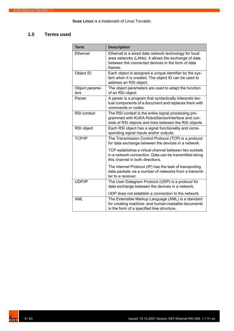
1.5 Terms used
Term DescriptionEthernet Ethernet is a wired data network technology for local
area networks (LANs). It allows the exchange of data between the connected devices in the form of data frames.
Object ID Each object is assigned a unique identifier by the sys-tem when it is created. The object ID can be used to address an RSI object.
Object parame-ters
The object parameters are used to adapt the function of an RSI object.
Parser A parser is a program that syntactically interprets tex-tual components of a document and replaces them with commands or codes.
RSI context The RSI context is the entire signal processing pro-grammed with KUKA.RobotSensorInterface and con-sists of RSI objects and links between the RSI objects.
RSI object Each RSI object has a signal functionality and corre-sponding signal inputs and/or outputs.
TCP/IP The Transmission Control Protocol (TCP) is a protocol for data exchange between the devices in a network.
TCP establishes a virtual channel between two sockets in a network connection. Data can be transmitted along this channel in both directions.
The Internet Protocol (IP) has the task of transporting data packets via a number of networks from a transmit-ter to a receiver.
UDP/IP The User Datagram Protocol (UDP) is a protocol for data exchange between the devices in a network.
UDP does not establish a connection to the network.XML The Extensible Markup Language (XML) is a standard
for creating machine- and human-readable documents in the form of a specified tree structure.
8 / 83 Issued: 10.12.2007 Version: KST Ethernet RSI XML 1.1 V1 en

Issu
2. Product description
2 Product description
2.1 Overview of KUKA.Ethernet RSI XML
KUKA.Ethernet RSI XML is an add-on technology package with the following functions:
Functions Cyclical data transmission from the robot controller to an external system in the interpolation cycle of 12 ms (e.g. position data, axis angles, operat-ing mode, etc.)Cyclical data transmission from an external system to the robot controller in the interpolation cycle of 12 ms (e.g. sensor data)Influencing the robot in the interpolation cycle of 12 msDirect intervention in the path planning of the robot
Characteristics Reloadable RSI object for communication with an external system, in con-formity with KUKA.RobotSensorInterface (RSI)Communications module with access to standard EthernetFreely definable inputs and outputs of the communication objectData exchange timeout monitoringExpandable data frame that is sent to the external system. The data frame consists of a fixed section that is always sent and a freely definable sec-tion.
Areas of application Implementation of external applications (e.g. transferring computing proc-esses to an external system)Implementation of extensive diagnosis and analysis functions on an exter-nal systemIntegration of microprocessor-supported sensors with a network connec-tionChecking the position of the robot with an external system
Communication The robot controller communicates with the external system via a real-time-ca-pable point-to-point network link. The exchanged data are transmitted via the Ethernet TCP/IP or UDP/IP protocol as XML strings.
2.2 Functional principle
Description If signal processing is activated with the communication object ST_COROB or ST_ETHERNET, the robot controller connects to the external system as a cli-ent.
9 / 83ed: 10.12.2007 Version: KST Ethernet RSI XML 1.1 V1 en
KUKA.Ethernet RSI XML 1.1
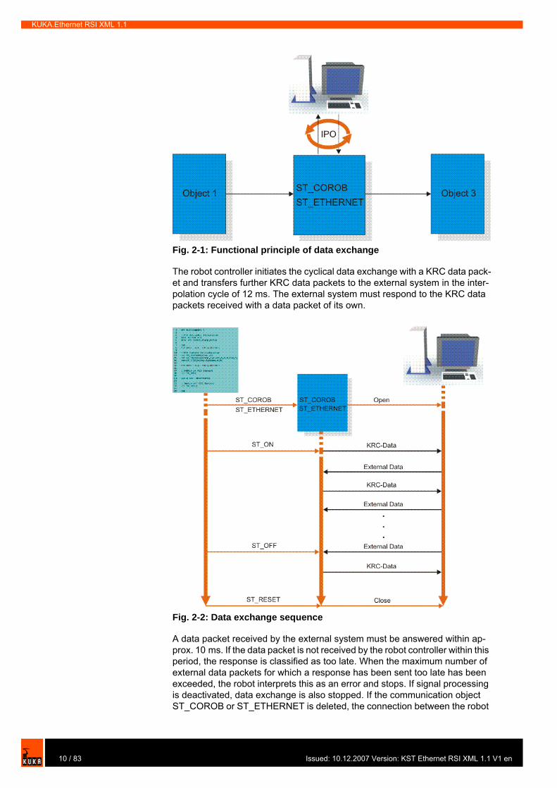
The robot controller initiates the cyclical data exchange with a KRC data pack-et and transfers further KRC data packets to the external system in the inter-polation cycle of 12 ms. The external system must respond to the KRC data packets received with a data packet of its own.
A data packet received by the external system must be answered within ap-prox. 10 ms. If the data packet is not received by the robot controller within this period, the response is classified as too late. When the maximum number of external data packets for which a response has been sent too late has been exceeded, the robot interprets this as an error and stops. If signal processing is deactivated, data exchange is also stopped. If the communication object ST_COROB or ST_ETHERNET is deleted, the connection between the robot
Fig. 2-1: Functional principle of data exchange
Fig. 2-2: Data exchange sequence
10 / 83 Issued: 10.12.2007 Version: KST Ethernet RSI XML 1.1 V1 en

Issu
2. Product description
controller and the external system is interrupted. Both sides exchange data in the form of XML strings.
ST_COROB (>>> 6.4.1 "Structure of the XML string when sending data (ERX-Demo.src)" page 62) (>>> 6.4.2 "Structure of the XML string when importing data (ERX-Demo.src)" page 64)ST_ETHERNET (>>> 6.5.1 "Structure of the XML string when sending data (ERXDemo_1.src)" page 65) (>>> 6.5.2 "Structure of the XML string when importing data (ERXDemo_1.src)" page 67)
11 / 83ed: 10.12.2007 Version: KST Ethernet RSI XML 1.1 V1 en

KUKA.Ethernet RSI XML 1.1
12 / 83 Issued: 10.12.2007 Version: KST Ethernet RSI XML 1.1 V1 en
Issu
3. Safety
3 Safety
3.1 General
3.1.1 Liability
The device described in these operating instructions is an industrial robot – called “robot system” in the following text – consisting of:
RobotConnecting cablesRobot controllerTeach pendantLinear unit (optional)Positioner (optional)Two-axis positioner (optional)Top-mounted cabinet (optional)
The robot system is built using state-of-the-art technology and in accordance with the recognized safety rules. Nevertheless, impermissible misuse of the robot system may constitute a risk to life and limb or cause damage to the ro-bot system and to other material property.
The robot system may only be used in perfect technical condition in accord-ance with its designated use and only by safety-conscious persons who are fully aware of the risks involved in its operation. Use of the robot system is sub-ject to compliance with these operating instructions and with the declaration of incorporation supplied together with the robot system. Any functional disor-ders affecting the safety of the robot system must be rectified immediately.
Safety information Safety information cannot be held against the KUKA Robot Group. Even if all safety instructions are followed, this is not a guarantee that the robot system will not cause personal injuries or material damage.
No modifications may be carried out to the robot system without the authori-zation of the KUKA Robot Group. Additional components (tools, software, etc.), not supplied by KUKA Robot Group, may be integrated into the robot system. The user is liable for any damage these components may cause to the robot system or to other material property.
3.1.2 Representation of warnings and notes
Safety Warnings marked with this pictogram are relevant to safety and must be ob-served.
Danger!This warning means that death, severe physical injury or substantial material damage will occur, if no precautions are taken.
Warning!This warning means that death, severe physical injury or substantial material damage may occur, if no precautions are taken.
Caution!This warning means that minor physical injuries or minor material damage may occur, if no precautions are taken.
13 / 83ed: 10.12.2007 Version: KST Ethernet RSI XML 1.1 V1 en
KUKA.Ethernet RSI XML 1.1
Notes Notes marked with this pictogram contain tips to make your work easier or ref-erences to further information.
3.1.3 Designated use of the robot system
The robot system is designed exclusively for the specified applications.
Using the robot system or its options for any other or additional purpose is con-sidered impermissible misuse. The manufacturer cannot be held liable for any damage resulting from such use. The risk lies entirely with the user.
Operating the robot system and its options within the limits of its designated use also involves continuous observance of the operating instructions with particular reference to the maintenance specifications.
Impermissible misuse
Any use or application deviating from the designated use is deemed to be im-permissible misuse; examples of such misuse include:
Transportation of persons and animalsUse as a climbing aidOperation outside the permissible operating parametersUse in potentially explosive environments
3.1.4 EC declaration of conformity and declaration of incorporation
Declaration of conformity
The system integrator must issue a declaration of conformity for the overall system in accordance with the Machinery Directive. The declaration of con-formity forms the basis for the CE mark for the system. The robot system must be operated in accordance with the applicable national laws, regulations and standards.
The robot controller is CE certified under the EMC Directive and the Low Volt-age Directive.
Declaration of incor-poration
A declaration of incorporation is provided for the robot system. This declara-tion of incorporation contains the stipulation that the robot system must not be commissioned until it complies with the provisions of the Machinery Directive.
3.1.5 Description of the robot system
The robot system consists of the following components:
RobotRobot controllerKCP teach pendantConnecting cables
Tips to make your work easier or references to further information.
Specific safety instructionsIn addition to the Safety chapter, the operating instructions for the robot sys-tem and its options contain further safety instructions. These must be ob-served.
Further information is contained in the technical data of the operating instruc-tions for the robot system and its options.
14 / 83 Issued: 10.12.2007 Version: KST Ethernet RSI XML 1.1 V1 en

Issu
3. Safety
External axes, e.g. linear unit, two-axis positioner, positioner (optional)Top-mounted cabinet (optional)SoftwareOptions, accessories
3.1.6 Terms used
Fig. 3-1: Example of a robot system
1 Linear unit 4 Connecting cables2 Robot 5 Robot controller3 Positioner 6 Teach pendant
Term DescriptionAxis range Range of an axis, in degrees, within which the
robot may move The axis range must be defined for each axis that is to be monitored.
Workspace The robot is allowed to move within its work-space. The workspace is derived from the indi-vidual axis ranges.
User The user of the robot system can be the man-agement, employer or delegated person respon-sible for use of the robot system.
Braking distance The braking distance is the distance covered by the robot and any optional external axes after the stop function has been triggered and before the robot comes to a standstill. The braking dis-tance is part of the danger zone.
Danger zone The danger zone consists of the workspace and the braking distances.
KCP The KCP (KUKA Control Panel) teach pendant has all the functions required for operating and programming the robot system.
15 / 83ed: 10.12.2007 Version: KST Ethernet RSI XML 1.1 V1 en

KUKA.Ethernet RSI XML 1.1
3.2 Personnel
Personnel must be instructed, before any work is commenced, in the type of work involved and what exactly it entails as well as any hazards which may ex-ist. Instruction must be repeated after particular incidents or technical modifi-cations.
Personnel include the system integrator responsible for integrating the robot system into the production cell, the user, and the operator or programmer of the robot system.
User The user of a robot system is responsible for its use. The user must ensure that it can be operated in complete safety and define all safety measures for personnel.
The user should check at specific intervals selected at his own discretion that the personnel attend to their work in a safety-conscious manner, are fully aware of the risks involved during operation and observe the operating instruc-tions for the robot system.
Robot system The robot system consists of the robot controller and robot, together with any options (e.g. KUKA linear unit, two-axis positioner, other positioner, top-mounted cabinet).
Safety zone The safety zone is situated outside the danger zone.
STOP 0(path-oriented braking)
In the case of a STOP 0, the drives are deacti-vated immediately and the brakes are applied. The robot and any external axes (optional) per-form path-oriented braking.
STOP 1(path-maintaining braking)
In the case of a STOP 1, the robot and any external axes (optional) perform path-maintain-ing braking. The drives are deactivated after 1 s and the brakes are applied.
STOP 2(ramp-down braking)
In the case of a STOP 2, the drives are not deac-tivated and the brakes are not applied. The robot and any external axes (optional) are braked with a normal braking ramp.
System integrator System integrators are people who safely inte-grate the robot system into a plant and commis-sion it.
T1 Test mode, Manual Reduced Velocity (<= 250 mm/s)
T2 Test mode, Manual High Velocity (> 250 mm/s)External axis Motion axis which is not part of the robot but
which is controlled using the robot controller, e.g. KUKA linear unit, two-axis positioner, Posiflex
Term Description
All persons working with the robot system must have read and understood the robot system documentation, including the safety chapter.
Installation, exchange, adjustment, operation, maintenance and repair must be performed only as specified in the operating instructions for the relevant component of the robot system and only by personnel specially trained for this purpose.
16 / 83 Issued: 10.12.2007 Version: KST Ethernet RSI XML 1.1 V1 en
Issu
3. Safety
System integrator The robot system is safely integrated into a plant by the system integrator.
The system integrator is responsible for the following tasks:
Installing the robot systemConnecting the robot systemImplementing the required facilitiesIssuing the declaration of conformityAttaching the CE mark
Operator The operator must meet the following preconditions:
The operator must have read and understood the robot system documen-tation, including the safety chapter.The operator must be trained for the work to be carried out.Work on the robot system must only be carried out by qualified personnel. These are people who, due to their specialist training, knowledge and ex-perience, and their familiarization with the relevant standards, are able to assess the work to be carried out and detect any potential dangers.
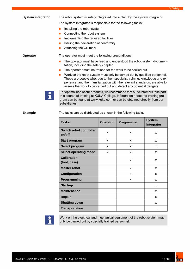
Example The tasks can be distributed as shown in the following table.
For optimal use of our products, we recommend that our customers take part in a course of training at KUKA College. Information about the training pro-gram can be found at www.kuka.com or can be obtained directly from our subsidiaries.
Tasks Operator ProgrammerSystem integrator
Switch robot controller on/off
x x x
Start program x x x
Select program x x x
Select operating mode x x x
Calibration (tool, base)
x x
Master robot x x
Configuration x x
Programming x x
Start-up x
Maintenance x
Repair x
Shutting down x
Transportation x
Work on the electrical and mechanical equipment of the robot system may only be carried out by specially trained personnel.
17 / 83ed: 10.12.2007 Version: KST Ethernet RSI XML 1.1 V1 en
KUKA.Ethernet RSI XML 1.1
3.3 Safety features of the robot system
3.3.1 Overview of the safety features
The following safety features are provided with the robot system:
Operator safetyEMERGENCY STOP pushbuttonEnabling switchesMode selector switchJog modeMechanical limit stopsSoftware limit switchesLabeling on the robot systemMechanical axis range limitation (optional)Axis range monitoring (optional)Release device (optional)KCP coupler (optional)
The function and triggering of the electronic safety equipment are monitored by the ESC safety logic.
3.3.2 ESC safety logic
The ESC (Electronic Safety Circuit) safety logic is a dual-channel computer-aided safety system. It permanently monitors all connected safety-relevant components. In the event of a fault or interruption in the safety circuit, the pow-er supply to the drives is shut off, thus bringing the robot system to a standstill.
Depending on the operating mode of the robot system, the ESC safety logic triggers a different stop reaction.
The ESC safety logic monitors the following inputs:
Operator safety Local EMERGENCY STOPExternal EMERGENCY STOPEnablingDrives OFFDrives ONOperating modesQualifying inputs
3.3.3 Mode selector switch
The robot system can be operated in the following modes:
Manual Reduced Velocity (T1)Manual High Velocity (T2)Automatic (AUT)
Danger!In the absence of functional safety equipment, the robot system can cause personal injury or material damage. If safety equipment is dismantled or de-activated, the robot system may not be operated.
18 / 83 Issued: 10.12.2007 Version: KST Ethernet RSI XML 1.1 V1 en
Issu
3. Safety
Automatic External (AUT EXT)
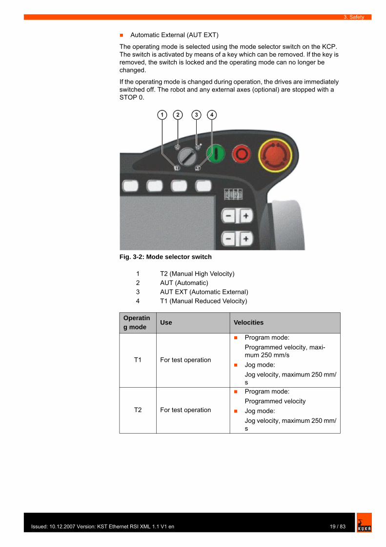
The operating mode is selected using the mode selector switch on the KCP. The switch is activated by means of a key which can be removed. If the key is removed, the switch is locked and the operating mode can no longer be changed.
If the operating mode is changed during operation, the drives are immediately switched off. The robot and any external axes (optional) are stopped with a STOP 0.
Fig. 3-2: Mode selector switch
1 T2 (Manual High Velocity)2 AUT (Automatic)3 AUT EXT (Automatic External)4 T1 (Manual Reduced Velocity)
Operating mode
Use Velocities
T1 For test operation
Program mode:Programmed velocity, maxi-mum 250 mm/sJog mode:Jog velocity, maximum 250 mm/s
T2 For test operation
Program mode:Programmed velocityJog mode:Jog velocity, maximum 250 mm/s
19 / 83ed: 10.12.2007 Version: KST Ethernet RSI XML 1.1 V1 en
KUKA.Ethernet RSI XML 1.1
3.3.4 Stop reactions
Stop reactions of the robot system are triggered in response to operator ac-tions or as a reaction to monitoring functions and error messages. The follow-ing table shows the different stop reactions according to the operating mode that has been set.
STOP 0, STOP 1 and STOP 2 are the stop definitions according to EN 60204.
AUT
For robot systems without higher-level controllers
Only possible with a connected safety cir-cuit
Program mode:Programmed velocityJog mode: not possible
AUT EXT
For robot systems with higher-level control-lers, e.g. PLC
Only possible with a connected safety cir-cuit
Program mode:Programmed velocityJog mode: not possible
Operating mode
Use Velocities
Trigger T1, T2 AUT, AUT EXTSafety gate opened - Path-maintaining brak-
ing(STOP 1)
EMERGENCY STOP pressed
Path-oriented braking(STOP 0)
Path-maintaining brak-ing
(STOP 1)Enabling switch released
Path-oriented braking(STOP 0)
-
Start key released Ramp-down braking(STOP 2)
-
"Drives OFF" key pressed
Path-oriented braking(STOP 0)
STOP key pressed Ramp-down braking(STOP 2)
Operating mode changed
Path-oriented braking(STOP 0)
Encoder error (DSE-RDC connec-tion broken)
Short-circuit braking(STOP 0)
Motion enable can-celed
Ramp-down braking(STOP 2)
Robot controller switched off
Power failure
Short-circuit braking(STOP 0)
20 / 83 Issued: 10.12.2007 Version: KST Ethernet RSI XML 1.1 V1 en

Issu
3. Safety
3.3.5 Workspace, safety zone and danger zone
Workspaces are to be restricted to the necessary minimum size. A workspace must be safeguarded using appropriate safeguards.
The safeguards (e.g. safety gate) must be situated inside the safety zone. If a safeguard is triggered, the robot and external axes are braked and come to a stop within the workspace or the braking range.
The danger zone consists of the workspace and the braking distances of the robot and external axes (optional). It must be safeguarded by means of pro-tective barriers to prevent danger to persons or the risk of material damage.
Stop reaction Drives Brakes Software PathRamp-down braking (STOP 2)
Drives remain on.
Brakes remain open.
Normal ramp which is used for acceleration and deceleration.
The path is maintained ex-actly.
Path-maintain-ing braking (STOP 1)
Drives are switched off after 1 second hardware delay.
Brakes are applied after 1 s at latest.
In this time the controller brakes the robot on the path using a steeper stop ramp.
The path is maintained ex-actly.
Path-oriented braking (STOP 0)
Drives are switched off immediately.
Brakes are applied immedi-ately.
The controller attempts to brake the robot on the path with the remaining energy. If the voltage is not sufficient, the robot leaves the programmed path.
The path is maintained approximately.
Short-circuit braking(STOP 0)
Drives are switched off immediately.
Brakes are applied immedi-ately.
Stop initiated by the drive hardware. Energy present in the intermedi-ate circuit is used for braking.
The path is left.
Fig. 3-3: Example of axis range A1
21 / 83ed: 10.12.2007 Version: KST Ethernet RSI XML 1.1 V1 en
KUKA.Ethernet RSI XML 1.1
3.3.6 Operator safety
The operator safety input is used for interlocking fixed guards. Safety equip-ment, such as safety gates, can be connected to the dual-channel input. If nothing is connected to this input, operation in Automatic mode is not possible. Operator safety is not active in the test modes T1 (Manual Reduced Velocity) and T2 (Manual High Velocity).
In the event of a loss of signal during Automatic operation (e.g. safety gate is opened), the drives are deactivated after 1 s and the robot and any external axes (optional) are stopped with a STOP 1. When the signal is applied again at the input (e.g. safety gate closed), Automatic operation can be resumed once the corresponding message has been acknowledged.
Operator safety can be connected via the peripheral interface on the robot controller.
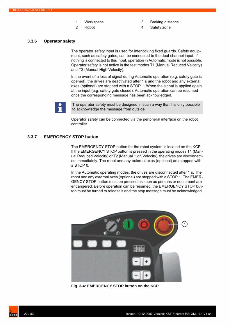
3.3.7 EMERGENCY STOP button
The EMERGENCY STOP button for the robot system is located on the KCP. If the EMERGENCY STOP button is pressed in the operating modes T1 (Man-ual Reduced Velocity) or T2 (Manual High Velocity), the drives are disconnect-ed immediately. The robot and any external axes (optional) are stopped with a STOP 0.
In the Automatic operating modes, the drives are disconnected after 1 s. The robot and any external axes (optional) are stopped with a STOP 1. The EMER-GENCY STOP button must be pressed as soon as persons or equipment are endangered. Before operation can be resumed, the EMERGENCY STOP but-ton must be turned to release it and the stop message must be acknowledged.
1 Workspace 3 Braking distance2 Robot 4 Safety zone
The operator safety must be designed in such a way that it is only possible to acknowledge the message from outside.
Fig. 3-4: EMERGENCY STOP button on the KCP
22 / 83 Issued: 10.12.2007 Version: KST Ethernet RSI XML 1.1 V1 en
Issu
3. Safety
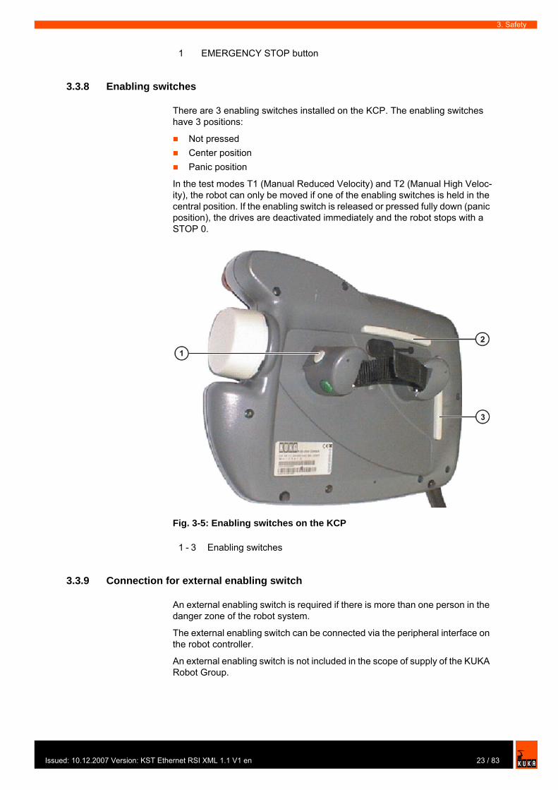
3.3.8 Enabling switches
There are 3 enabling switches installed on the KCP. The enabling switches have 3 positions:
Not pressedCenter positionPanic position
In the test modes T1 (Manual Reduced Velocity) and T2 (Manual High Veloc-ity), the robot can only be moved if one of the enabling switches is held in the central position. If the enabling switch is released or pressed fully down (panic position), the drives are deactivated immediately and the robot stops with a STOP 0.
3.3.9 Connection for external enabling switch
An external enabling switch is required if there is more than one person in the danger zone of the robot system.
The external enabling switch can be connected via the peripheral interface on the robot controller.
An external enabling switch is not included in the scope of supply of the KUKA Robot Group.
1 EMERGENCY STOP button
Fig. 3-5: Enabling switches on the KCP
1 - 3 Enabling switches
23 / 83ed: 10.12.2007 Version: KST Ethernet RSI XML 1.1 V1 en

KUKA.Ethernet RSI XML 1.1
3.3.10 Jog mode
In the operating modes T1 (Manual Reduced Velocity) and T2 (Manual High Velocity), the robot can only execute programs in jog mode. This means that it is necessary to hold down an enabling switch and the Start key in order to execute a program. If the enabling switch is released or pressed fully down (panic position), the drives are deactivated immediately and the robot and any external axes (optional) stop with a STOP 0. Releasing the Start key causes the robot system to be stopped with a STOP 2.
3.3.11 Mechanical end stops
The axis ranges of main axes A 1 to A 3 and wrist axis A 5 of the robot are lim-ited by means of mechanical limit stops with a buffer.
Additional mechanical limit stops can be installed on the external axes.
3.3.12 Software limit switches
The axis ranges of all robot axes are limited by means of adjustable software limit switches. These software limit switches only serve as machine protection and must be adjusted in such a way that the robot cannot hit the mechanical limit stops.
The software limit switches are set during commissioning of a robot system.
3.3.13 Overview of operating modes and active safety features
The following table indicates the operating modes in which the safety features are active.
Danger!If the robot or an external axis hits an obstruction or a buffer on the mechan-ical end stop or axis range limitation, this can result in material damage to the robot system. The KUKA Robot Group must be consulted before the robot system is put back into operation (>>> 8 "KUKA Service" page 73). The af-fected buffer must immediately be replaced with a new one. If a robot (or ex-ternal axis) collides with a buffer at more than 250 mm/s, the robot (or external axis) must be exchanged or recommissioning must be carried out by the KUKA Robot Group.
Further information is contained in the operating and programming instruc-tions.
Safety features T1 T2 AUT AUT EXT
Operator safety - - active active
EMERGENCY STOP button
active (STOP
0)
active (STOP
0)
active (STOP
1)
active (STOP 1)
Enabling switches active active - -
Reduced velocity in program mode
active - - -
Jog mode active active - -
Software limit switches active active active active
24 / 83 Issued: 10.12.2007 Version: KST Ethernet RSI XML 1.1 V1 en
Issu
3. Safety
3.3.14 Mechanical axis range limitation (option)
Most robots can be fitted with mechanical axis range limitation in main axes A 1 to A 3. The adjustable axis range limitation systems restrict the working range to the required minimum. This increases personal safety and protection of the system.
3.3.15 Axis range monitoring (option)
Most robots can be fitted with dual-channel axis range monitoring systems in main axes A 1 to A 3. The safety zone for an axis can be adjusted and moni-tored using an axis range monitoring system. This increases personal safety and protection of the system.
3.3.16 Release device (option)
Description The release device can be used to move the robot mechanically after an acci-dent or malfunction. The release device can be used for the main axis drive motors and, depending on the robot variant, also for the wrist axis drive mo-tors. It is only for use in exceptional circumstances and emergencies (e.g. for freeing people). After use of the release device, the affected motors must be exchanged.
Procedure 1. Switch off the robot controller and secure it (e.g. with a padlock) to prevent unauthorized persons from switching it on again.
2. Remove the protective cap from the motor3. Push the release device onto the corresponding motor and move the axis
in the desired direction.The directions are indicated with arrows on the motors. It is necessary to overcome the resistance of the mechanical motor brake and any other loads acting on the axis.
3.3.17 KCP coupler (optional)
The KCP coupler allows the KCP to be connected and disconnected with the robot controller running.
This option can be retrofitted.
This option can be retrofitted.
Caution!The motors reach temperatures during operation which can cause burns to the skin. Appropriate safety precautions must be taken.
Warning!Moving an axis with the release device can damage the motor brake. This can result in personal injury and material damage. After using the release de-vice, the affected motor must be exchanged.
Further information is contained in the robot operating instructions.
25 / 83ed: 10.12.2007 Version: KST Ethernet RSI XML 1.1 V1 en
KUKA.Ethernet RSI XML 1.1
3.3.18 External safeguards
EMERGENCY STOP Additional EMERGENCY STOP devices can be connected via the peripheral interface on the robot controller or linked together by means of higher-level controllers (e.g. PLC).
The input/output signals and any necessary external power supplies must en-sure a safe state in the case of an EMERGENCY STOP.
Safety fences Requirements on safety fences are:
Safety fences must withstand all forces that are likely to occur in the course of operation, whether from inside or outside the enclosure.Safety fences must not, themselves, constitute a hazard.It is imperative to comply with the minimum clearances from the danger zone.
Safety gates Requirements on safety gates are:
The number of safety gates in the fencing must be kept to a minimum.All safety gates must be safeguarded by means of an operator safety sys-tem.Automatic mode must be prevented until all safety gates are closed.For additional protection in Automatic mode, the safety gate can be me-chanically locked by means of a safety system.If a safety gate is opened in Automatic mode, it must trigger an EMER-GENCY STOP function.If the safety gate is closed, the robot cannot be started immediately in Au-tomatic mode. The message on the control panel must be acknowledged.
Other safety equipment
Other safety equipment must be integrated into the system in accordance with the corresponding standards and regulations.
3.3.19 Labeling on the robot system
All plates, labels, symbols and marks constitute safety-relevant parts of the ro-bot system. They must not be modified or removed.
Labeling on the robot system consists of:
Rating plates
Warning!If the KCP is disconnected, the system can no longer be deactivated by means of the EMERGENCY STOP button on the KCP. An external EMER-GENCY STOP must be connected to the peripheral interface to prevent per-sonal injury and material damage.
Further information is contained in the robot controller operating instructions.
Further information is contained in the corresponding standards and regula-tions.
Further information is contained in the corresponding standards and regula-tions.
26 / 83 Issued: 10.12.2007 Version: KST Ethernet RSI XML 1.1 V1 en
Issu
3. Safety
Warning labelsSafety symbolsDesignation labelsCable markingsIdentification plates
3.4 Safety measures
3.4.1 General safety measures
The robot system may only be used in perfect technical condition in accord-ance with its designated use and only by safety-conscious persons. Operator errors can result in personal injury and damage to property.
It is important to be prepared for possible movements of the robot system even after the robot controller has been switched off and locked. Incorrect installa-tion (e.g. overload) or mechanical defects (e.g. brake defect) can cause the ro-bot or external axes to sag. If work is to be carried out on a switched-off robot system, the robot and external axes must first be moved into a position in which they are unable to move on their own, whether the payload is mounted or not. If this is not possible, the robot and external axes must be secured by appropriate means.
KCP If the KCP is not connected, it must be removed from the system, as the EMERGENCY STOP button on the KCP is not functional in such a case.
If there is more than one KCP in operation in the overall system, it must be en-sured that the KCPs and EMERGENCY STOP buttons can be unambiguously assigned to the corresponding robot system. There must be no possibility of mixing them up in an emergency situation.
External keyboard, external mouse
An external keyboard and/or external mouse may only be connected during service work (e.g. installation). If a keyboard and/or mouse is connected, the system can no longer be operated safely. If a keyboard and/or mouse is con-nected, the system must not be operated and there must be no persons within the system.
The KCP must not be used as long as an external keyboard and/or external mouse are connected.
The external keyboard and/or external mouse must be removed as soon as the service work is completed.
Faults The following tasks must be carried out in the case of faults to the robot sys-tem:
Further information can be found in the operating instructions of the robot, lin-ear unit, positioner and robot controller.
Danger!In the absence of functional safety equipment, the robot system can cause personal injury or material damage. If safety equipment is dismantled or de-activated, the robot system may not be operated.
Warning!The motors reach temperatures during operation which can cause burns to the skin. Contact should be avoided if at all possible. If necessary, appropri-ate protective equipment must be used.
27 / 83ed: 10.12.2007 Version: KST Ethernet RSI XML 1.1 V1 en
KUKA.Ethernet RSI XML 1.1
Switch off the robot controller and secure it (e.g. with a padlock) to prevent unauthorized persons from switching it on again. Indicate the fault by means of a label with a corresponding warning.Keep a record of the faults.Eliminate the fault and carry out a function test.
3.4.2 Transportation
Robot The prescribed transport position of the robot must be observed. Transporta-tion must be carried out in accordance with the robot operating instructions.
Robot controller The robot controller must be transported and installed in an upright position. Avoid vibrations and impacts during transportation in order to prevent damage to the robot controller.
Transportation must be carried out in accordance with the operating instruc-tions for the robot controller.
External axis (optional)
The prescribed transport position of the external axis (e.g. KUKA linear unit, two-axis positioner, etc.) must be observed. Transportation must be carried out in accordance with the operating instructions for the external axis.
3.4.3 Start-up
Function test It must be ensured that no persons or objects are present within the danger zone of the robot during the function test.
The following must be checked during the function test:
The robot system is installed and connected. There are no foreign bodies or destroyed, loose parts on the robot system.All safety devices and protective measures are complete and fully func-tional.All electrical connections are correct.The peripheral devices are correctly connected.The external environment corresponds to the permissible values indicated in the operating instructions.
The passwords for logging onto the KUKA System Software as “Expert” and “Administrator” must be changed before start-up and must only be communi-cated to authorized personnel.
Danger!The robot controller is preconfigured for the specific robot system. If cables are interchanged, the robot and the external axes (optional) may receive in-correct data and can thus cause personal injury or material damage. If a sys-tem consists of more than one robot, always connect the connecting cables to the robots and their corresponding robot controllers.
Caution!If the internal cabinet temperature of the robot controller differs greatly from the ambient temperature, condensation can form, which may cause damage to the electrical components. Do not put the robot controller into operation un-til the internal temperature of the cabinet has adjusted to the ambient temper-ature.
28 / 83 Issued: 10.12.2007 Version: KST Ethernet RSI XML 1.1 V1 en
Issu
3. Safety
Setting It must be ensured that the rating plate on the robot controller has the same machine data as those entered in the declaration of incorporation. The ma-chine data on the rating plate of the robot and the external axes (optional) must be entered during start-up.
3.4.4 Virus protection and network security
The user of the robot system is responsible for ensuring that the software is always safeguarded with the latest virus protection. If the robot controller is in-tegrated into a network that is connected to the company network or to the In-ternet, it is advisable to protect this robot network against external risks by means of a firewall.
3.4.5 Programming
The following safety measures must be carried out during programming:
It must be ensured that no persons are present within the danger zone of the robot system during programming.New or modified programs must always be tested first in Manual Reduced Velocity mode (T1).If the drives are not required, they must be switched off to prevent the robot or the external axes (optional) from being moved unintentionally.The robot, tooling or external axes (optional) must never touch or project beyond the safety fence. Components, tooling and other objects must not become jammed due to the motion of the robot system, nor must they lead to short-circuits or be liable to fall off.
The following safety measures must be carried out during programming in the danger zone of the robot system:
The robot and the external axes (optional) must only be moved at Manual Reduced Velocity (max. 250 mm/s). In this way, persons have enough time to move out of the way of hazardous motions of the robot system or to stop the robot system. To prevent other persons from being able to move the robot or external axes (optional), the KCP must be kept within reach of the programmer.If two or more persons are working in the system at the same time, they must all use an enabling switch. While the robot or external axes (optional) are being moved, all persons must remain in constant visual contact and have an unrestricted view of the robot system.
3.4.6 Simulation
Simulation programs do not correspond exactly to reality. Robot programs cre-ated in simulation programs must be tested in the system in Manual Reduced Velocity mode (SSTEP T1). It may be necessary to modify the program.
Caution!Incorrect machine data can result in material damage. Check that the correct machine data have been loaded; if not, load the correct machine data.
For optimal use of our products, we recommend that our customers carry out a regular virus scan. Information about security updates can be found at www.kuka.com.
29 / 83ed: 10.12.2007 Version: KST Ethernet RSI XML 1.1 V1 en

KUKA.Ethernet RSI XML 1.1
3.4.7 Automatic mode
Automatic mode is only permissible in compliance with the following safety measures.
The prescribed safety equipment is present and operational.There are no persons in the system.The defined working procedures are adhered to.
If the robot or an external axis (optional) comes to a standstill for no apparent reason, the danger zone must not be entered until the EMERGENCY STOP function has been triggered.
3.4.8 Maintenance and repair
The purpose of maintenance and repair work is to ensure that the system is kept operational or, in the event of a fault, to return the system to an operation-al state. Repair work includes troubleshooting in addition to the actual repair itself.
The following safety measures must be carried out when working on the robot system:
Carry out work outside the danger zone. If work inside the danger zone is necessary, the user must define additional safety measures to ensure the safe protection of personnel.Switch off the robot controller and secure it (e.g. with a padlock) to prevent unauthorized persons from switching it on again. If it is necessary to carry out work with the robot controller switched on, the user must define addi-tional safety measures to ensure the safe protection of personnel.If it is necessary to carry out work with the robot controller switched on, this may only be done in operating mode T1.Label the system with a sign indicating that work is in progress. This sign must remain in place, even during temporary interruptions to the work.The EMERGENCY STOP systems must remain active. If safety equip-ment is deactivated during maintenance or repair work, it must be reacti-vated immediately after the work is completed.
Faulty components must be replaced using new components with the same article numbers or equivalent components approved by the KUKA Robot Group for this purpose.
Cleaning and preventive maintenance work is to be carried out in accordance with the operating instructions.
Robot controller Even when the robot controller is switched off, parts connected to peripheral devices may still carry voltage. The external power sources must therefore be switched off or isolated if work is to be carried out on the robot controller.
The ESD regulations must be adhered to when working on components in the robot controller.
Voltages in excess of 50 V (up to 600 V) can be present in the KPS (KUKA Power Supply), the KSDs (KUKA Servo Drives) and the intermediate-circuit connecting cables up to 5 minutes after the robot controller has been switched off. To prevent life-threatening injuries, no work may be carried out on the ro-bot system in this time.
Foreign matter, such as swarf, water and dust, must be prevented from enter-ing the robot controller.
30 / 83 Issued: 10.12.2007 Version: KST Ethernet RSI XML 1.1 V1 en
Issu
3. Safety
Counterbalancing system
Some robot variants are equipped with a hydropneumatic, spring or gas cylin-der counterbalancing system.
The hydropneumatic and gas cylinder counterbalancing systems are pressure equipment and, as such, are subject to obligatory equipment monitoring. De-pending on the robot variant, the counterbalancing systems correspond to cat-egory II or III, fluid group 2, of the Pressure Equipment Directive
The user must comply with the applicable national laws, regulations and standards pertaining to pressure equipment.
The following safety measures must be carried out when working on the coun-terbalancing system:
The robot assemblies supported by the counterbalancing systems must be secured.Work on the counterbalancing systems must only be carried out by quali-fied personnel.
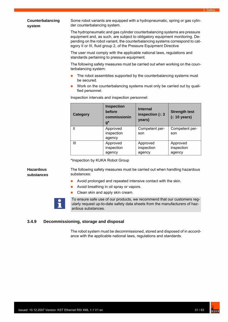
Inspection intervals and inspection personnel:
*Inspection by KUKA Robot Group
Hazardous substances
The following safety measures must be carried out when handling hazardous substances:
Avoid prolonged and repeated intensive contact with the skin.Avoid breathing in oil spray or vapors.Clean skin and apply skin cream.
3.4.9 Decommissioning, storage and disposal
The robot system must be decommissioned, stored and disposed of in accord-ance with the applicable national laws, regulations and standards.
Category
Inspection before commissioning*
Internal inspection (≤ 3 years)
Strength test (≤ 10 years)
II Approved inspection agency
Competent per-son
Competent per-son
III Approved inspection agency
Approved inspection agency
Approved inspection agency
To ensure safe use of our products, we recommend that our customers reg-ularly request up-to-date safety data sheets from the manufacturers of haz-ardous substances.
31 / 83ed: 10.12.2007 Version: KST Ethernet RSI XML 1.1 V1 en

KUKA.Ethernet RSI XML 1.1
3.5 Applied norms and regulations
Name Definition Edition73/23/EEC Low Voltage Directive:
Council Directive of 19 February 1973 on the harmonization of the laws of Member States relating to electrical equipment designed for use within certain voltage limits
1993
89/336/EEC EMC Directive:
Council Directive of 3 May 1989 on the approximation of the laws of the Member States relating to electromagnetic com-patibility
1993
97/23/EC Pressure Equipment Directive:
Directive of the European Parliament and of the Council of 29 May 1997 on the approximation of the laws of the Member States concerning pressure equipment
1997
98/37/EC Machinery Directive:
Directive of the European Parliament and of the Council of 22 June 1998 on the approximation of the laws of the Member States relating to machinery
1998
EN 418 Safety of machinery:
EMERGENCY STOP equipment, func-tional aspects; principles for design
1993
EN 563 Safety of machinery:
Temperatures of touchable surfaces - Ergonomics data to establish tempera-ture limit values for hot surfaces
2000
EN 614-1 Safety of machinery:
Ergonomic design principles – Part 1: Terms and general principles
1995
EN 775 Industrial robots:
SafetyEN 954-1 Safety of machinery:
Safety-related parts of control systems - Part 1: General principles for design
1997
EN 55011 Industrial, scientific and medical (ISM) radio-frequency equipment – Radio dis-turbance characteristics – Limits and methods of measurement
2003
EN 60204-1 Safety of machinery:
Electrical equipment of machines - Part 1: General requirements
1998
EN 61000-4-4 Electromagnetic compatibility (EMC):
Part 4-4: Testing and measurement tech-niques - Electrical fast transient/burst immunity test
2002
32 / 83 Issued: 10.12.2007 Version: KST Ethernet RSI XML 1.1 V1 en

Issu
3. Safety
EN 61000-4-5 Electromagnetic compatibility (EMC):
Part 4-5: Testing and measurement tech-niques; Surge immunity test
2001
EN 61000-6-2 Electromagnetic compatibility (EMC):
Part 6-2: Generic standards - Immunity for industrial environments
2002
EN 61000-6-4 Electromagnetic compatibility (EMC):
Part 6-4: Generic standards; Emission standard for industrial environments
2002
EN 61800-3 Adjustable speed electrical power drive systems:
Part 3: EMC product standard including specific test methods
2001
EN ISO 10218-1 Industrial robots:
Safety
2006
EN ISO 12100-1 Safety of machinery:
Basic concepts, general principles for design - Part 1: Basic terminology, meth-odology
2004
EN ISO 12100-2 Safety of machinery:
Basic concepts, general principles for design - Part 2: Technical principles
2004
Name Definition Edition
33 / 83ed: 10.12.2007 Version: KST Ethernet RSI XML 1.1 V1 en

KUKA.Ethernet RSI XML 1.1
34 / 83 Issued: 10.12.2007 Version: KST Ethernet RSI XML 1.1 V1 en

Issu
4. Installation
4 Installation
4.1 System requirements
Hardware Robot controller:KR C2KR C2 ed05KR C3KR C2 sr
External system:processor-supported system with real-time-capable operating system and network cardmicroprocessor-supported sensor with network card for use in sensor applications
Robot controller: MFC2 or MFC3 with installed KUKA network card if KR C2 ed05 or KR C2 sr is to be usedNetwork cable for switch, hub or crossed network cable for direct connec-tion
Software KUKA System Software (KSS) 5.4, 5.5, 7.0
External system Real-time-capable network card with 10/100 Mbit in full duplex modeReal-time communication via TCP/IP protocolXML parser for generating XML strings with the data for the robot control-ler
Recommendation XML parser:
Microsoft .Net XML parserGnome parser, SuSE LINUX
4.2 PCI slot assignment
Overview
The PC slots can be fitted with the following plug-in cards:
Fig. 4-1: PCI slots
35 / 83ed: 10.12.2007 Version: KST Ethernet RSI XML 1.1 V1 en

KUKA.Ethernet RSI XML 1.1
4.3 Installing KUKA.Ethernet RSI XML
Description During installation of KUKA.Ethernet RSI XML, a network connection for the real-time communication is assigned to the VxWorks real-time operating sys-tem. Depending on the specific robot controller used, VxWorks is assigned the following network connection:
Precondition User group “Expert”Windows interface (CTRL+ESC)Installed network cardIf KUKA.RoboTeam is being used: switches at the network nodes
Procedure 1. Start the program SetupAll.exe from the CD-ROM.2. Enter the network address of the robot controller in the window that opens.
The files are copied onto the hard drive.
3. Confirm the reboot prompt with OK.4. Reboot the robot controller.
Slot Plug-in card1 Interbus card (FOC) (optional)
Interbus card (copper) (optional)LPDN scanner card (optional)Profibus master/slave card (optional)CN_EthernetIP card (optional)
2 LPDN scanner card (optional)3 KVGA card4 DSE-IBS-C33 AUX card (optional)5 MFC3 card6 Network card (optional)
LPDN scanner card (optional)Profibus master/slave card (optional)LIBO-2PCI card (optional)KUKA modem card (optional)
7 free
Robot controller Network connectionKR C2KR C3
Network connection on the MFC2
KR C2 ed05KR C2 sr
Network connection on the additionally installed KUKA network card
The IP address range 192.0.1.x is reserved and is disabled for applications. Configuring the VxWorks network connection with this address range results in a system error in the KUKA system software. It is no longer possible to boot the robot controller.
If no window requesting a network address appears, a network interface has already been installed. The IP address can be changed later. (>>> 4.3.1 "Modifying the IP address when using KSS 5.x" page 37) (>>> 4.3.2 "Modifying the IP address when using KSS 7.0" page 37)
36 / 83 Issued: 10.12.2007 Version: KST Ethernet RSI XML 1.1 V1 en
Issu
4. Installation
LOG file A LOG file is created under C:\KRC\ROBOTER\LOG.
4.3.1 Modifying the IP address when using KSS 5.x
Precondition User group “Expert”Windows interface (CTRL+ESC)
Procedure 1. Open the file C:\Windows\vxWin.ini.2. Modify the IP address under e={......}.3. Save and close.4. Reboot the robot controller.
4.3.2 Modifying the IP address when using KSS 7.0
Precondition User group “Expert”Windows interface (CTRL+ESC)
Procedure 1. Open the file C:\KRC\ROBOTER\INIT\progress.ini.2. Modify the IP address under IPADDR_ELPCI.3. Save and close.4. Reboot the robot controller.
4.4 Uninstalling KUKA.Ethernet RSI XML
Precondition KUKA.Ethernet RSI XML is installed.User group “Expert”Windows interface (CTRL+ESC)
Procedure 1. Start the UnInstall.exe program in the directory C:\KRC_OPTION\ETH-ERNETRSIXML\UNINST. Uninstallation is prepared.
2. Confirm the reboot prompt with OK.3. Reboot the robot controller.
LOG file A LOG file is created under C:\KRC\ROBOTER\LOG.
4.5 Reinstalling KUKA.Ethernet RSI XML
Precondition KUKA.Ethernet RSI XML has been uninstalled.User group “Expert”Windows interface (CTRL+ESC)
Procedure 1. Start the ReInstall.exe program in the directory C:\KRC_OPTION\ETH-ERNETRSIXML\REINST. Setup is prepared.
2. Confirm the reboot prompt with OK.3. Reboot the robot controller.
LOG file A LOG file is created under C:\KRC\ROBOTER\LOG.
During installation, the network card is automatically assigned to the Vx-Works kernel. The Windows driver is deleted.
37 / 83ed: 10.12.2007 Version: KST Ethernet RSI XML 1.1 V1 en

KUKA.Ethernet RSI XML 1.1
38 / 83 Issued: 10.12.2007 Version: KST Ethernet RSI XML 1.1 V1 en

Issu
5. Programming
5 Programming
5.1 RSI object ST_COROB
Description The real-time communication between the robot controller and the external system is implemented using the RSI object ST_COROB. The RSI object ST_COROB must be created, linked and configured in the KRL program.
On creating the RSI object, the connection with the external system is estab-lished. The connection is only terminated when ST_COROB is deleted.
Elements of the RSI object ST_COROB:
Instance parameters, which are assigned when ST_COROB is created to initialize the RSI object.Object parameters for adapting the function of ST_COROB.Object inputs for loading data from the RSI context and forwarding it to the external system.Object outputs for forwarding received data from the external system to RSI objects.
With signal processing activated, ST_COROB always sends a fixed data frame in the interpolation cycle. This data frame can be expanded to include the data at the object inputs. The data frame to be sent can be expanded to include the following data:
6 LONG INTEGER values5 BOOLEAN values1 8-bit LONG INTEGER value
ST_COROB also expects a fixed data frame from the external system. This data frame can be expanded to include the data that should be present at the object outputs for further processing. The imported data frame can be expand-ed to include the following data:
3 x 6 DOUBLE values1 8-bit LONG INTEGER value
Further information about programming with RSI commands can be found in the documentation KUKA.RobotSensorInterface (RSI).
If the RSI object ST_COROB is deleted in the KRL program, it cannot be cre-ated again until 2 s after it has been deleted. If ST_COROB is created within the 2 s, the network interface may become blocked.
39 / 83ed: 10.12.2007 Version: KST Ethernet RSI XML 1.1 V1 en
KUKA.Ethernet RSI XML 1.1
5.1.1 Creating ST_COROB
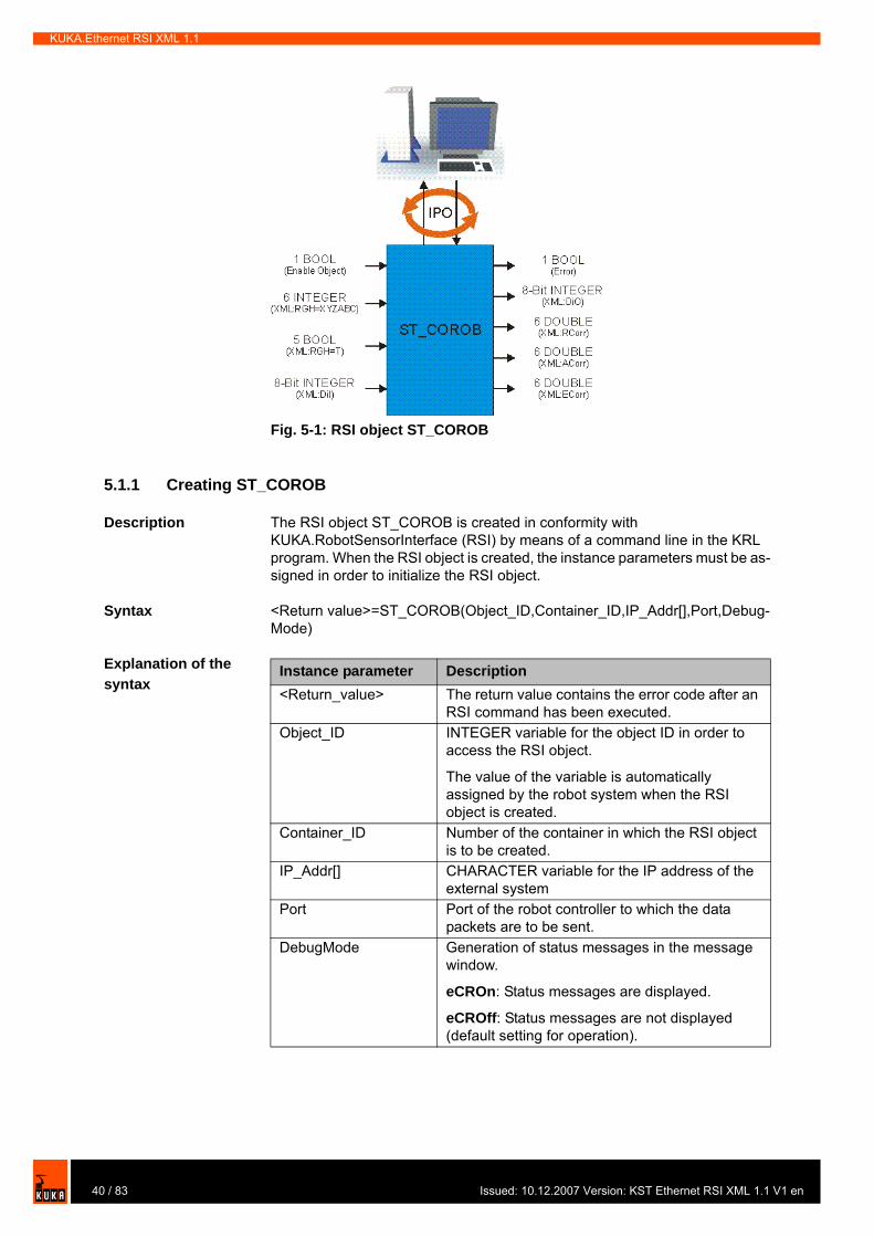
Description The RSI object ST_COROB is created in conformity with KUKA.RobotSensorInterface (RSI) by means of a command line in the KRL program. When the RSI object is created, the instance parameters must be as-signed in order to initialize the RSI object.
Syntax <Return value>=ST_COROB(Object_ID,Container_ID,IP_Addr[],Port,Debug-Mode)
Explanation of the syntax
Fig. 5-1: RSI object ST_COROB
Instance parameter Description<Return_value> The return value contains the error code after an
RSI command has been executed.Object_ID INTEGER variable for the object ID in order to
access the RSI object.
The value of the variable is automatically assigned by the robot system when the RSI object is created.
Container_ID Number of the container in which the RSI object is to be created.
IP_Addr[] CHARACTER variable for the IP address of the external system
Port Port of the robot controller to which the data packets are to be sent.
DebugMode Generation of status messages in the message window.
eCROn: Status messages are displayed.
eCROff: Status messages are not displayed (default setting for operation).
40 / 83 Issued: 10.12.2007 Version: KST Ethernet RSI XML 1.1 V1 en
Issu
5. Programming
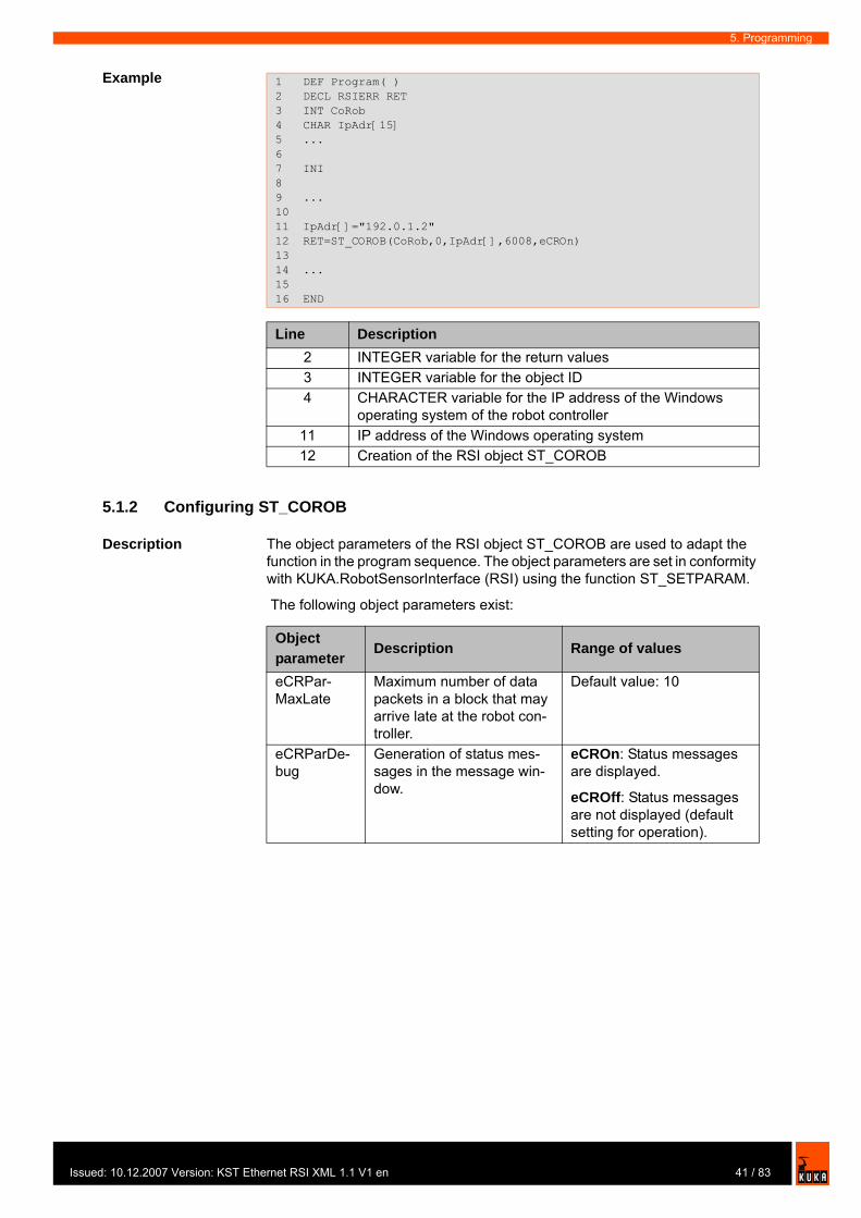
Example
5.1.2 Configuring ST_COROB
Description The object parameters of the RSI object ST_COROB are used to adapt the function in the program sequence. The object parameters are set in conformity with KUKA.RobotSensorInterface (RSI) using the function ST_SETPARAM.
The following object parameters exist:
1 DEF Program( )2 DECL RSIERR RET3 INT CoRob4 CHAR IpAdr[15]5 ...6 7 INI8 9 ...10 11 IpAdr[]="192.0.1.2"12 RET=ST_COROB(CoRob,0,IpAdr[],6008,eCROn)13 14 ...15 16 END
Line Description2 INTEGER variable for the return values3 INTEGER variable for the object ID4 CHARACTER variable for the IP address of the Windows
operating system of the robot controller11 IP address of the Windows operating system12 Creation of the RSI object ST_COROB
Object parameter
Description Range of values
eCRPar-MaxLate
Maximum number of data packets in a block that may arrive late at the robot con-troller.
Default value: 10
eCRParDe-bug
Generation of status mes-sages in the message win-dow.
eCROn: Status messages are displayed.
eCROff: Status messages are not displayed (default setting for operation).
41 / 83ed: 10.12.2007 Version: KST Ethernet RSI XML 1.1 V1 en
KUKA.Ethernet RSI XML 1.1
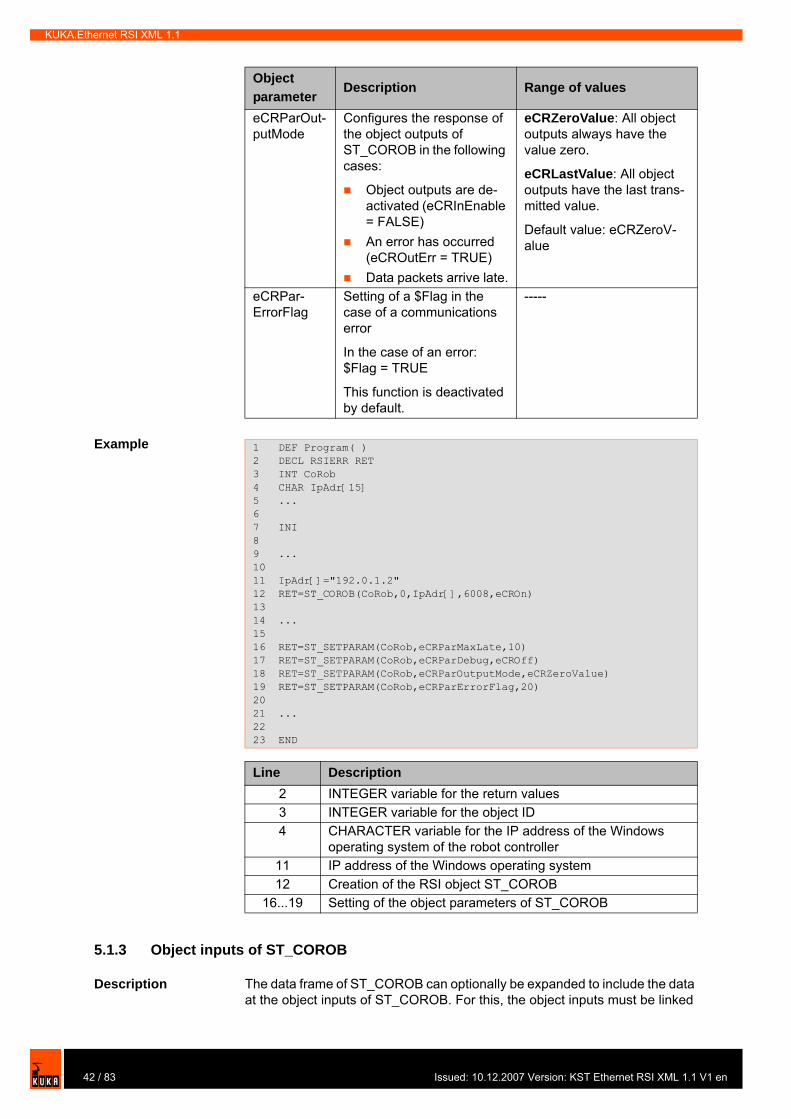
Example
5.1.3 Object inputs of ST_COROB
Description The data frame of ST_COROB can optionally be expanded to include the data at the object inputs of ST_COROB. For this, the object inputs must be linked
eCRParOut-putMode
Configures the response of the object outputs of ST_COROB in the following cases:
Object outputs are de-activated (eCRInEnable = FALSE)An error has occurred (eCROutErr = TRUE)Data packets arrive late.
eCRZeroValue: All object outputs always have the value zero.
eCRLastValue: All object outputs have the last trans-mitted value.
Default value: eCRZeroV-alue
eCRPar-ErrorFlag
Setting of a $Flag in the case of a communications error
In the case of an error: $Flag = TRUE
This function is deactivated by default.
-----
Object parameter
Description Range of values
1 DEF Program( )2 DECL RSIERR RET3 INT CoRob4 CHAR IpAdr[15]5 ...6 7 INI8 9 ...10 11 IpAdr[]="192.0.1.2"12 RET=ST_COROB(CoRob,0,IpAdr[],6008,eCROn)13 14 ...15 16 RET=ST_SETPARAM(CoRob,eCRParMaxLate,10)17 RET=ST_SETPARAM(CoRob,eCRParDebug,eCROff)18 RET=ST_SETPARAM(CoRob,eCRParOutputMode,eCRZeroValue)19 RET=ST_SETPARAM(CoRob,eCRParErrorFlag,20)20 21 ...22 23 END
Line Description2 INTEGER variable for the return values3 INTEGER variable for the object ID4 CHARACTER variable for the IP address of the Windows
operating system of the robot controller11 IP address of the Windows operating system12 Creation of the RSI object ST_COROB
16...19 Setting of the object parameters of ST_COROB
42 / 83 Issued: 10.12.2007 Version: KST Ethernet RSI XML 1.1 V1 en
Issu
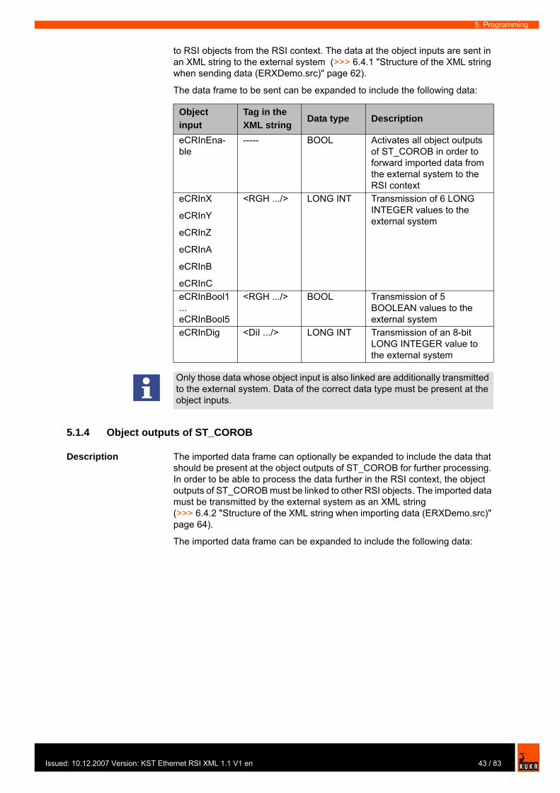
5. Programming
to RSI objects from the RSI context. The data at the object inputs are sent in an XML string to the external system (>>> 6.4.1 "Structure of the XML string when sending data (ERXDemo.src)" page 62).
The data frame to be sent can be expanded to include the following data:
5.1.4 Object outputs of ST_COROB
Description The imported data frame can optionally be expanded to include the data that should be present at the object outputs of ST_COROB for further processing. In order to be able to process the data further in the RSI context, the object outputs of ST_COROB must be linked to other RSI objects. The imported data must be transmitted by the external system as an XML string (>>> 6.4.2 "Structure of the XML string when importing data (ERXDemo.src)" page 64).
The imported data frame can be expanded to include the following data:
Object input
Tag in the XML string
Data type Description
eCRInEna-ble
----- BOOL Activates all object outputs of ST_COROB in order to forward imported data from the external system to the RSI context
eCRInX
eCRInY
eCRInZ
eCRInA
eCRInB
eCRInC
<RGH .../> LONG INT Transmission of 6 LONG INTEGER values to the external system
eCRInBool1 ... eCRInBool5
<RGH .../> BOOL Transmission of 5 BOOLEAN values to the external system
eCRInDig <DiI .../> LONG INT Transmission of an 8-bit LONG INTEGER value to the external system
Only those data whose object input is also linked are additionally transmitted to the external system. Data of the correct data type must be present at the object inputs.
43 / 83ed: 10.12.2007 Version: KST Ethernet RSI XML 1.1 V1 en
KUKA.Ethernet RSI XML 1.1
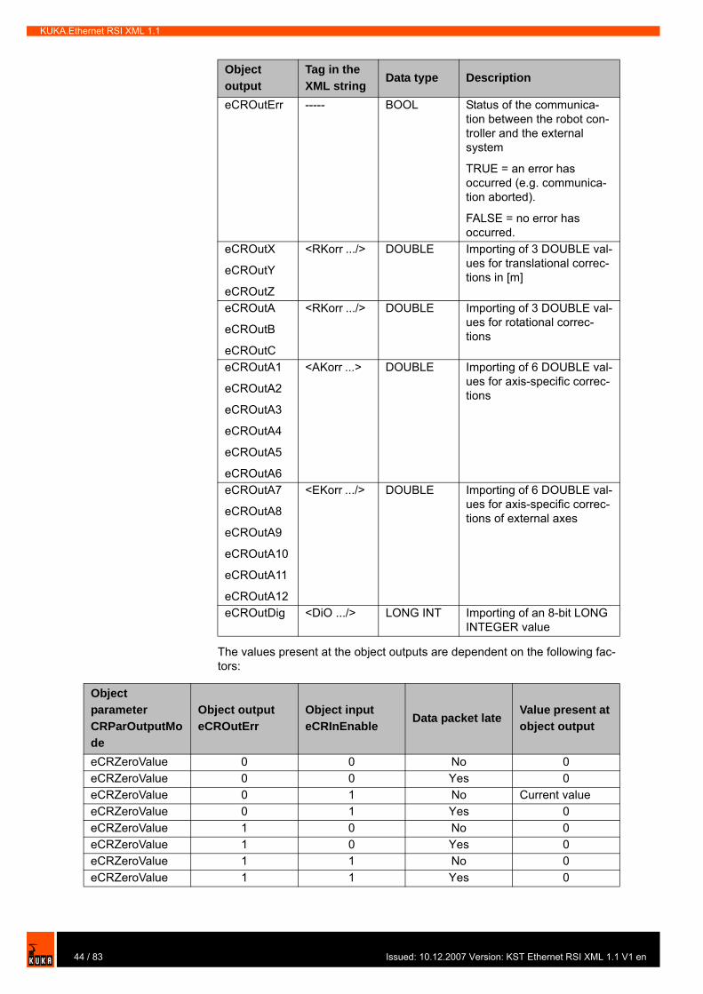
The values present at the object outputs are dependent on the following fac-tors:
Object output
Tag in the XML string
Data type Description
eCROutErr ----- BOOL Status of the communica-tion between the robot con-troller and the external system
TRUE = an error has occurred (e.g. communica-tion aborted).
FALSE = no error has occurred.
eCROutX
eCROutY
eCROutZ
<RKorr .../> DOUBLE Importing of 3 DOUBLE val-ues for translational correc-tions in [m]
eCROutA
eCROutB
eCROutC
<RKorr .../> DOUBLE Importing of 3 DOUBLE val-ues for rotational correc-tions
eCROutA1
eCROutA2
eCROutA3
eCROutA4
eCROutA5
eCROutA6
<AKorr ...> DOUBLE Importing of 6 DOUBLE val-ues for axis-specific correc-tions
eCROutA7
eCROutA8
eCROutA9
eCROutA10
eCROutA11
eCROutA12
<EKorr .../> DOUBLE Importing of 6 DOUBLE val-ues for axis-specific correc-tions of external axes
eCROutDig <DiO .../> LONG INT Importing of an 8-bit LONG INTEGER value
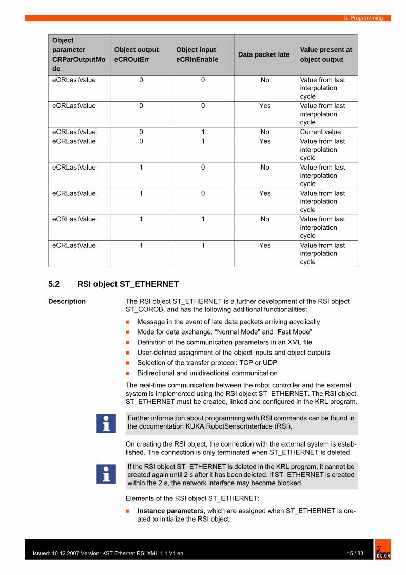
Object parameter CRParOutputMode
Object output eCROutErr
Object input eCRInEnable
Data packet lateValue present at object output
eCRZeroValue 0 0 No 0eCRZeroValue 0 0 Yes 0eCRZeroValue 0 1 No Current valueeCRZeroValue 0 1 Yes 0eCRZeroValue 1 0 No 0eCRZeroValue 1 0 Yes 0eCRZeroValue 1 1 No 0eCRZeroValue 1 1 Yes 0
44 / 83 Issued: 10.12.2007 Version: KST Ethernet RSI XML 1.1 V1 en
Issu
5. Programming
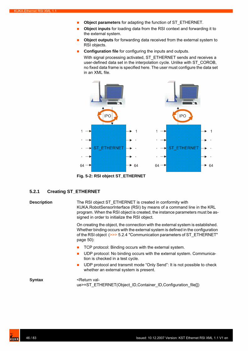
5.2 RSI object ST_ETHERNET
Description The RSI object ST_ETHERNET is a further development of the RSI object ST_COROB, and has the following additional functionalities:
Message in the event of late data packets arriving acyclicallyMode for data exchange: “Normal Mode” and “Fast Mode”Definition of the communication parameters in an XML file User-defined assignment of the object inputs and object outputsSelection of the transfer protocol: TCP or UDPBidirectional and unidirectional communication
The real-time communication between the robot controller and the external system is implemented using the RSI object ST_ETHERNET. The RSI object ST_ETHERNET must be created, linked and configured in the KRL program.
On creating the RSI object, the connection with the external system is estab-lished. The connection is only terminated when ST_ETHERNET is deleted.
Elements of the RSI object ST_ETHERNET:
Instance parameters, which are assigned when ST_ETHERNET is cre-ated to initialize the RSI object.
eCRLastValue 0 0 No Value from last interpolation cycle
eCRLastValue 0 0 Yes Value from last interpolation cycle
eCRLastValue 0 1 No Current valueeCRLastValue 0 1 Yes Value from last
interpolation cycle
eCRLastValue 1 0 No Value from last interpolation cycle
eCRLastValue 1 0 Yes Value from last interpolation cycle
eCRLastValue 1 1 No Value from last interpolation cycle
eCRLastValue 1 1 Yes Value from last interpolation cycle
Object parameter CRParOutputMode
Object output eCROutErr
Object input eCRInEnable
Data packet lateValue present at object output
Further information about programming with RSI commands can be found in the documentation KUKA.RobotSensorInterface (RSI).
If the RSI object ST_ETHERNET is deleted in the KRL program, it cannot be created again until 2 s after it has been deleted. If ST_ETHERNET is created within the 2 s, the network interface may become blocked.
45 / 83ed: 10.12.2007 Version: KST Ethernet RSI XML 1.1 V1 en
KUKA.Ethernet RSI XML 1.1
Object parameters for adapting the function of ST_ETHERNET.Object inputs for loading data from the RSI context and forwarding it to the external system.Object outputs for forwarding data received from the external system to RSI objects.Configuration file for configuring the inputs and outputs.With signal processing activated, ST_ETHERNET sends and receives a user-defined data set in the interpolation cycle. Unlike with ST_COROB, no fixed data frame is specified here. The user must configure the data set in an XML file.
5.2.1 Creating ST_ETHERNET
Description The RSI object ST_ETHERNET is created in conformity with KUKA.RobotSensorInterface (RSI) by means of a command line in the KRL program. When the RSI object is created, the instance parameters must be as-signed in order to initialize the RSI object.
On creating the object, the connection with the external system is established. Whether binding occurs with the external system is defined in the configuration of the RSI object (>>> 5.2.4 "Communication parameters of ST_ETHERNET" page 50):
TCP protocol: Binding occurs with the external system.UDP protocol: No binding occurs with the external system. Communica-tion is checked in a test cycle.UDP protocol and transmit mode “Only Send”: It is not possible to check whether an external system is present.
Syntax <Return val-ue>=ST_ETHERNET(Object_ID,Container_ID,Configuration_file[])
Fig. 5-2: RSI object ST_ETHERNET
46 / 83 Issued: 10.12.2007 Version: KST Ethernet RSI XML 1.1 V1 en

Issu
5. Programming
Explanation of the syntax
Example
5.2.2 Configuring ST_ETHERNET
Description The object parameters of the RSI object ST_ETHERNET are used to adapt the function in the program sequence. The object parameters are set in con-formity with KUKA.RobotSensorInterface (RSI) using the function ST_SETPARAM.
Instance parameter Description<Return_value> The return value contains the error code after an
RSI command has been executed.Object_ID INTEGER variable for the object ID in order to
access the RSI object.
The value of the variable is automatically assigned by the robot system when the RSI object is created.
Container_ID Number of the container in which the RSI object is to be created.
Configuration_file[] CHARACTER variable for the name of the con-figuration file. The name of the configuration file can also be entered here directly, e.g. “ERXcon-fig.xml”.
1 DEF Program( )2 DECL RSIERR RET3 INT hEthernet45 ...6 7 INI8 9 ...10 11 RET = ST_ETHERNET(hEthernet,0,"ERXconfig.xml") 1213 ...14 15 END
Line Description2 INTEGER variable for the return values3 INTEGER variable for the object ID11 Creation of the RSI object ST_ETHERNET
47 / 83ed: 10.12.2007 Version: KST Ethernet RSI XML 1.1 V1 en
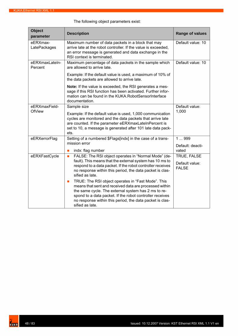
KUKA.Ethernet RSI XML 1.1
The following object parameters exist:
Object parameter
Description Range of values
eERXmax-LatePackages
Maximum number of data packets in a block that may arrive late at the robot controller. If the value is exceeded, an error message is generated and data exchange in the RSI context is terminated.
Default value: 10
eERXmaxLateIn-Percent
Maximum percentage of data packets in the sample which are allowed to arrive late.
Example: If the default value is used, a maximum of 10% of the data packets are allowed to arrive late.
Note: If the value is exceeded, the RSI generates a mes-sage if this RSI function has been activated. Further infor-mation can be found in the KUKA.RobotSensorInterface documentation.
Default value: 10
eERXmaxField-OfView
Sample size
Example: If the default value is used, 1,000 communication cycles are monitored and the data packets that arrive late are counted. If the parameter eERXmaxLateInPercent is set to 10, a message is generated after 101 late data pack-ets.
Default value: 1,000
eERXerrorFlag Setting of a numbered $Flags[indx] in the case of a trans-mission error
indx: flag number
1 ... 999
Default: deacti-vated
eERXFastCycle FALSE: The RSI object operates in “Normal Mode” (de-fault). This means that the external system has 10 ms to respond to a data packet. If the robot controller receives no response within this period, the data packet is clas-sified as late.TRUE: The RSI object operates in “Fast Mode”. This means that sent and received data are processed within the same cycle. The external system has 2 ms to re-spond to a data packet. If the robot controller receives no response within this period, the data packet is clas-sified as late.
TRUE, FALSE
Default value: FALSE
48 / 83 Issued: 10.12.2007 Version: KST Ethernet RSI XML 1.1 V1 en
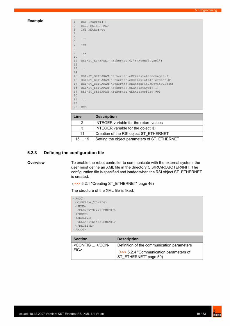
Issu
5. Programming
Example
5.2.3 Defining the configuration file
Overview To enable the robot controller to communicate with the external system, the user must define an XML file in the directory C:\KRC\ROBOTER\INIT. The configuration file is specified and loaded when the RSI object ST_ETHERNET is created.
(>>> 5.2.1 "Creating ST_ETHERNET" page 46)
The structure of the XML file is fixed:
1 DEF Program( )2 DECL RSIERR RET3 INT hEthernet4 5 ...6 7 INI8 9 ...10 11 RET=ST_ETHERNET(hEthernet,0,"ERXconfig.xml") 1213 ... 1415 RET=ST_SETPARAM(hEthernet,eERXmaxLatePackages,3) 16 RET=ST_SETPARAM(hEthernet,eERXmaxLateInPercent,8) 17 RET=ST_SETPARAM(hEthernet,eERXmaxFieldOfView,2345) 18 RET=ST_SETPARAM(hEthernet,eERXFastCycle,1)19 RET=ST_SETPARAM(hEthernet,eERXerrorFlag,99)20 21 ... 2223 END
Line Description2 INTEGER variable for the return values3 INTEGER variable for the object ID11 Creation of the RSI object ST_ETHERNET
15 ... 19 Setting the object parameters of ST_ETHERNET
<ROOT> <CONFIG></CONFIG> <SEND> <ELEMENTS></ELEMENTS> </SEND> <RECEIVE> <ELEMENTS></ELEMENTS> </RECEIVE> </ROOT>
Section Description<CONFIG ... </CON-FIG>
Definition of the communication parameters
(>>> 5.2.4 "Communication parameters of ST_ETHERNET" page 50)
49 / 83ed: 10.12.2007 Version: KST Ethernet RSI XML 1.1 V1 en
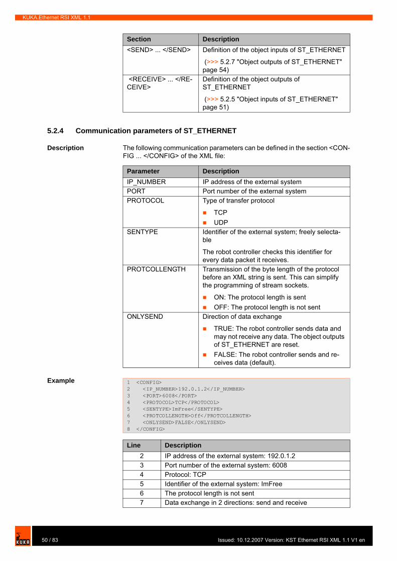
KUKA.Ethernet RSI XML 1.1
5.2.4 Communication parameters of ST_ETHERNET
Description The following communication parameters can be defined in the section <CON-FIG ... </CONFIG> of the XML file:
Example
<SEND> ... </SEND> Definition of the object inputs of ST_ETHERNET
(>>> 5.2.7 "Object outputs of ST_ETHERNET" page 54)
<RECEIVE> ... </RE-CEIVE>
Definition of the object outputs of ST_ETHERNET
(>>> 5.2.5 "Object inputs of ST_ETHERNET" page 51)
Section Description
Parameter DescriptionIP_NUMBER IP address of the external systemPORT Port number of the external systemPROTOCOL Type of transfer protocol
TCPUDP
SENTYPE Identifier of the external system; freely selecta-ble
The robot controller checks this identifier for every data packet it receives.
PROTCOLLENGTH Transmission of the byte length of the protocol before an XML string is sent. This can simplify the programming of stream sockets.
ON: The protocol length is sentOFF: The protocol length is not sent
ONLYSEND Direction of data exchange
TRUE: The robot controller sends data and may not receive any data. The object outputs of ST_ETHERNET are reset.FALSE: The robot controller sends and re-ceives data (default).
1 <CONFIG>2 <IP_NUMBER>192.0.1.2</IP_NUMBER> 3 <PORT>6008</PORT>4 <PROTOCOL>TCP</PROTOCOL>5 <SENTYPE>ImFree</SENTYPE>6 <PROTCOLLENGTH>Off</PROTCOLLENGTH>7 <ONLYSEND>FALSE</ONLYSEND> 8 </CONFIG>
Line Description2 IP address of the external system: 192.0.1.23 Port number of the external system: 60084 Protocol: TCP5 Identifier of the external system: ImFree6 The protocol length is not sent7 Data exchange in 2 directions: send and receive
50 / 83 Issued: 10.12.2007 Version: KST Ethernet RSI XML 1.1 V1 en
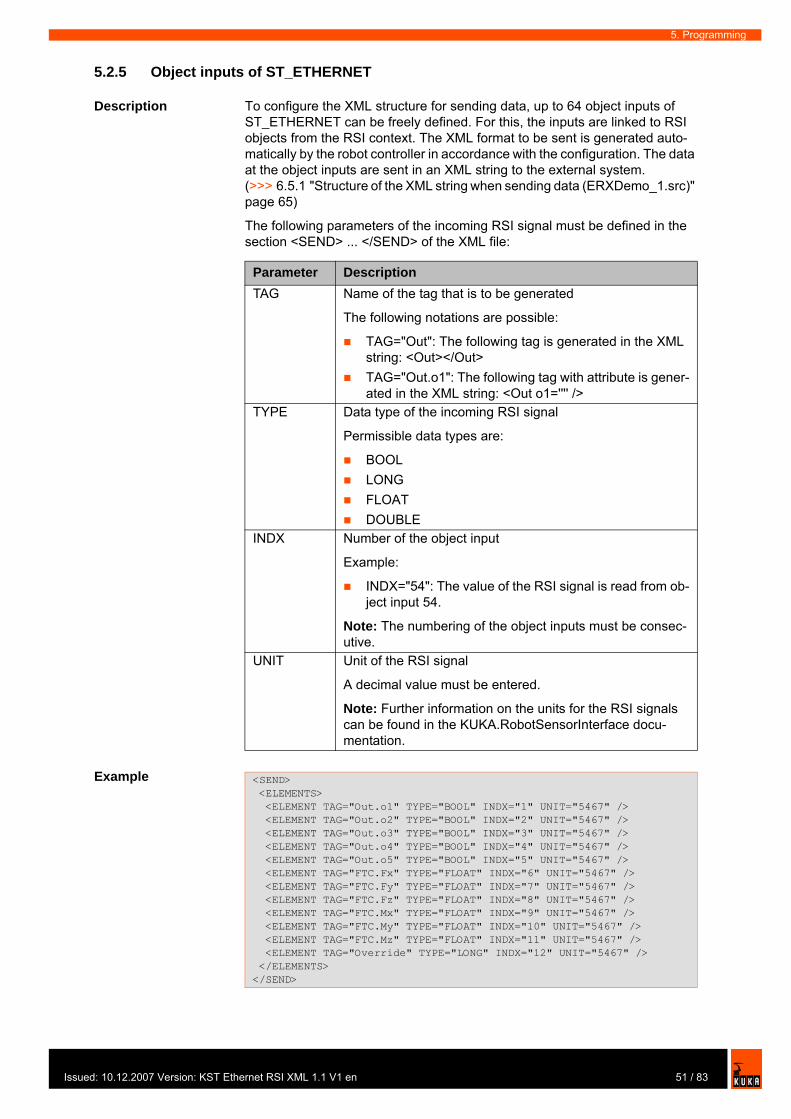
Issu
5. Programming
5.2.5 Object inputs of ST_ETHERNET
Description To configure the XML structure for sending data, up to 64 object inputs of ST_ETHERNET can be freely defined. For this, the inputs are linked to RSI objects from the RSI context. The XML format to be sent is generated auto-matically by the robot controller in accordance with the configuration. The data at the object inputs are sent in an XML string to the external system. (>>> 6.5.1 "Structure of the XML string when sending data (ERXDemo_1.src)" page 65)
The following parameters of the incoming RSI signal must be defined in the section <SEND> ... </SEND> of the XML file:
Example
Parameter DescriptionTAG Name of the tag that is to be generated
The following notations are possible:
TAG="Out": The following tag is generated in the XML string: <Out></Out>TAG="Out.o1": The following tag with attribute is gener-ated in the XML string: <Out o1='''' />
TYPE Data type of the incoming RSI signal
Permissible data types are:
BOOLLONGFLOATDOUBLE
INDX Number of the object input
Example:
INDX="54": The value of the RSI signal is read from ob-ject input 54.
Note: The numbering of the object inputs must be consec-utive.
UNIT Unit of the RSI signal
A decimal value must be entered.
Note: Further information on the units for the RSI signals can be found in the KUKA.RobotSensorInterface docu-mentation.
<SEND> <ELEMENTS> <ELEMENT TAG="Out.o1" TYPE="BOOL" INDX="1" UNIT="5467" /> <ELEMENT TAG="Out.o2" TYPE="BOOL" INDX="2" UNIT="5467" /> <ELEMENT TAG="Out.o3" TYPE="BOOL" INDX="3" UNIT="5467" /> <ELEMENT TAG="Out.o4" TYPE="BOOL" INDX="4" UNIT="5467" /> <ELEMENT TAG="Out.o5" TYPE="BOOL" INDX="5" UNIT="5467" /> <ELEMENT TAG="FTC.Fx" TYPE="FLOAT" INDX="6" UNIT="5467" /> <ELEMENT TAG="FTC.Fy" TYPE="FLOAT" INDX="7" UNIT="5467" /> <ELEMENT TAG="FTC.Fz" TYPE="FLOAT" INDX="8" UNIT="5467" /> <ELEMENT TAG="FTC.Mx" TYPE="FLOAT" INDX="9" UNIT="5467" /> <ELEMENT TAG="FTC.My" TYPE="FLOAT" INDX="10" UNIT="5467" /> <ELEMENT TAG="FTC.Mz" TYPE="FLOAT" INDX="11" UNIT="5467" /> <ELEMENT TAG="Override" TYPE="LONG" INDX="12" UNIT="5467" /> </ELEMENTS></SEND>
51 / 83ed: 10.12.2007 Version: KST Ethernet RSI XML 1.1 V1 en
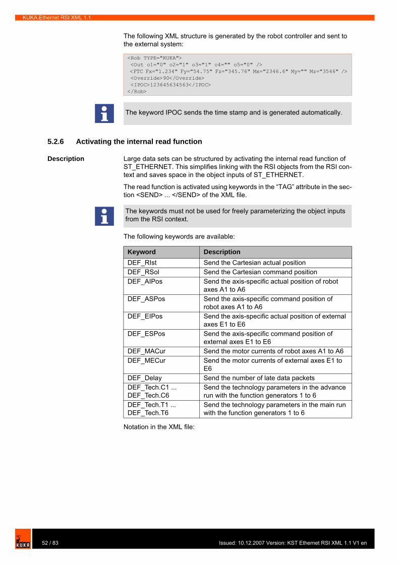
KUKA.Ethernet RSI XML 1.1
The following XML structure is generated by the robot controller and sent to the external system:
5.2.6 Activating the internal read function
Description Large data sets can be structured by activating the internal read function of ST_ETHERNET. This simplifies linking with the RSI objects from the RSI con-text and saves space in the object inputs of ST_ETHERNET.
The read function is activated using keywords in the “TAG” attribute in the sec-tion <SEND> ... </SEND> of the XML file.
The following keywords are available:
Notation in the XML file:
<Rob TYPE="KUKA"> <Out o1="0" o2="1" o3="1" o4="" o5="0" /> <FTC Fx="1.234" Fy="54.75" Fz="345.76" Mx="2346.6" My="" Mz="3546" /> <Override>90</Override> <IPOC>123645634563</IPOC></Rob>
The keyword IPOC sends the time stamp and is generated automatically.
The keywords must not be used for freely parameterizing the object inputs from the RSI context.
Keyword DescriptionDEF_RIst Send the Cartesian actual positionDEF_RSol Send the Cartesian command positionDEF_AIPos Send the axis-specific actual position of robot
axes A1 to A6DEF_ASPos Send the axis-specific command position of
robot axes A1 to A6DEF_EIPos Send the axis-specific actual position of external
axes E1 to E6DEF_ESPos Send the axis-specific command position of
external axes E1 to E6 DEF_MACur Send the motor currents of robot axes A1 to A6DEF_MECur Send the motor currents of external axes E1 to
E6DEF_Delay Send the number of late data packetsDEF_Tech.C1 ... DEF_Tech.C6
Send the technology parameters in the advance run with the function generators 1 to 6
DEF_Tech.T1 ... DEF_Tech.T6
Send the technology parameters in the main run with the function generators 1 to 6
52 / 83 Issued: 10.12.2007 Version: KST Ethernet RSI XML 1.1 V1 en
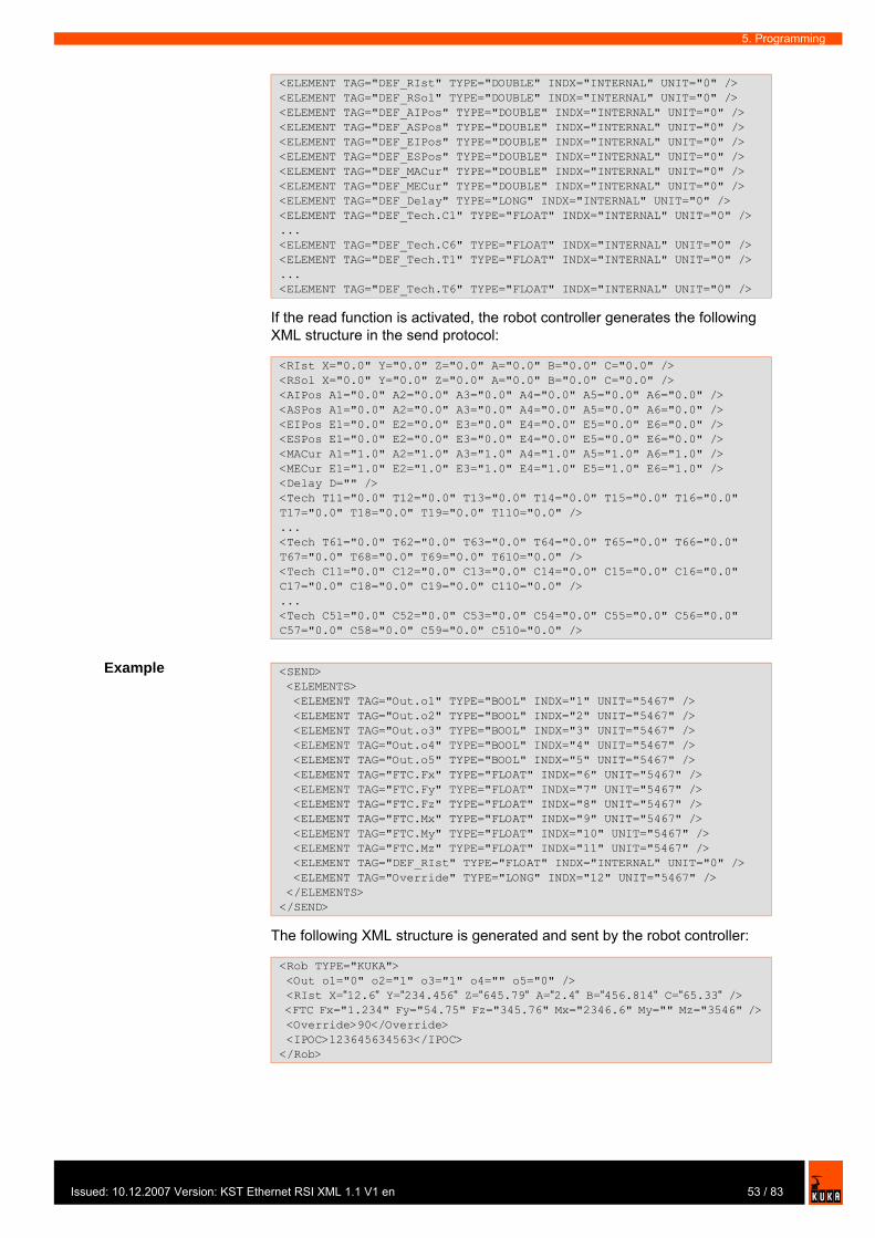
Issu
5. Programming
If the read function is activated, the robot controller generates the following XML structure in the send protocol:
Example
The following XML structure is generated and sent by the robot controller:
<ELEMENT TAG="DEF_RIst" TYPE="DOUBLE" INDX="INTERNAL" UNIT="0" /><ELEMENT TAG="DEF_RSol" TYPE="DOUBLE" INDX="INTERNAL" UNIT="0" /><ELEMENT TAG="DEF_AIPos" TYPE="DOUBLE" INDX="INTERNAL" UNIT="0" /><ELEMENT TAG="DEF_ASPos" TYPE="DOUBLE" INDX="INTERNAL" UNIT="0" /><ELEMENT TAG="DEF_EIPos" TYPE="DOUBLE" INDX="INTERNAL" UNIT="0" /><ELEMENT TAG="DEF_ESPos" TYPE="DOUBLE" INDX="INTERNAL" UNIT="0" /><ELEMENT TAG="DEF_MACur" TYPE="DOUBLE" INDX="INTERNAL" UNIT="0" /><ELEMENT TAG="DEF_MECur" TYPE="DOUBLE" INDX="INTERNAL" UNIT="0" /><ELEMENT TAG="DEF_Delay" TYPE="LONG" INDX="INTERNAL" UNIT="0" /><ELEMENT TAG="DEF_Tech.C1" TYPE="FLOAT" INDX="INTERNAL" UNIT="0" />...<ELEMENT TAG="DEF_Tech.C6" TYPE="FLOAT" INDX="INTERNAL" UNIT="0" /><ELEMENT TAG="DEF_Tech.T1" TYPE="FLOAT" INDX="INTERNAL" UNIT="0" />...<ELEMENT TAG="DEF_Tech.T6" TYPE="FLOAT" INDX="INTERNAL" UNIT="0" />
<RIst X="0.0" Y="0.0" Z="0.0" A="0.0" B="0.0" C="0.0" /><RSol X="0.0" Y="0.0" Z="0.0" A="0.0" B="0.0" C="0.0" /><AIPos A1="0.0" A2="0.0" A3="0.0" A4="0.0" A5="0.0" A6="0.0" /><ASPos A1="0.0" A2="0.0" A3="0.0" A4="0.0" A5="0.0" A6="0.0" /><EIPos E1="0.0" E2="0.0" E3="0.0" E4="0.0" E5="0.0" E6="0.0" /><ESPos E1="0.0" E2="0.0" E3="0.0" E4="0.0" E5="0.0" E6="0.0" /><MACur A1="1.0" A2="1.0" A3="1.0" A4="1.0" A5="1.0" A6="1.0" /><MECur E1="1.0" E2="1.0" E3="1.0" E4="1.0" E5="1.0" E6="1.0" /><Delay D="" /><Tech T11="0.0" T12="0.0" T13="0.0" T14="0.0" T15="0.0" T16="0.0" T17="0.0" T18="0.0" T19="0.0" T110="0.0" />...<Tech T61="0.0" T62="0.0" T63="0.0" T64="0.0" T65="0.0" T66="0.0" T67="0.0" T68="0.0" T69="0.0" T610="0.0" /><Tech C11="0.0" C12="0.0" C13="0.0" C14="0.0" C15="0.0" C16="0.0" C17="0.0" C18="0.0" C19="0.0" C110="0.0" />...<Tech C51="0.0" C52="0.0" C53="0.0" C54="0.0" C55="0.0" C56="0.0" C57="0.0" C58="0.0" C59="0.0" C510="0.0" />
<SEND> <ELEMENTS> <ELEMENT TAG="Out.o1" TYPE="BOOL" INDX="1" UNIT="5467" /> <ELEMENT TAG="Out.o2" TYPE="BOOL" INDX="2" UNIT="5467" /> <ELEMENT TAG="Out.o3" TYPE="BOOL" INDX="3" UNIT="5467" /> <ELEMENT TAG="Out.o4" TYPE="BOOL" INDX="4" UNIT="5467" /> <ELEMENT TAG="Out.o5" TYPE="BOOL" INDX="5" UNIT="5467" /> <ELEMENT TAG="FTC.Fx" TYPE="FLOAT" INDX="6" UNIT="5467" /> <ELEMENT TAG="FTC.Fy" TYPE="FLOAT" INDX="7" UNIT="5467" /> <ELEMENT TAG="FTC.Fz" TYPE="FLOAT" INDX="8" UNIT="5467" /> <ELEMENT TAG="FTC.Mx" TYPE="FLOAT" INDX="9" UNIT="5467" /> <ELEMENT TAG="FTC.My" TYPE="FLOAT" INDX="10" UNIT="5467" /> <ELEMENT TAG="FTC.Mz" TYPE="FLOAT" INDX="11" UNIT="5467" /> <ELEMENT TAG="DEF_RIst" TYPE="FLOAT" INDX="INTERNAL" UNIT="0" /> <ELEMENT TAG="Override" TYPE="LONG" INDX="12" UNIT="5467" /> </ELEMENTS></SEND>
<Rob TYPE="KUKA"> <Out o1="0" o2="1" o3="1" o4="" o5="0" /> <RIst X=“12.6“ Y=“234.456“ Z=“645.79“ A=“2.4“ B=“456.814“ C=“65.33“ /> <FTC Fx="1.234" Fy="54.75" Fz="345.76" Mx="2346.6" My="" Mz="3546" /> <Override>90</Override> <IPOC>123645634563</IPOC></Rob>
53 / 83ed: 10.12.2007 Version: KST Ethernet RSI XML 1.1 V1 en
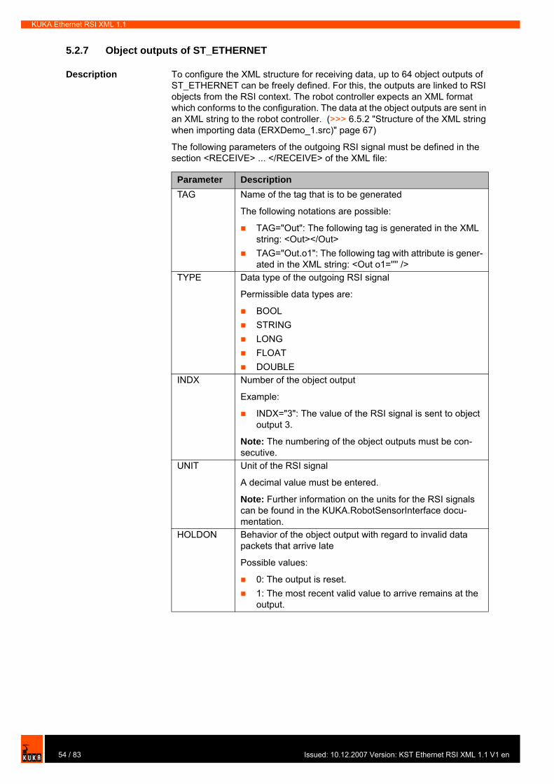
KUKA.Ethernet RSI XML 1.1
5.2.7 Object outputs of ST_ETHERNET
Description To configure the XML structure for receiving data, up to 64 object outputs of ST_ETHERNET can be freely defined. For this, the outputs are linked to RSI objects from the RSI context. The robot controller expects an XML format which conforms to the configuration. The data at the object outputs are sent in an XML string to the robot controller. (>>> 6.5.2 "Structure of the XML string when importing data (ERXDemo_1.src)" page 67)
The following parameters of the outgoing RSI signal must be defined in the section <RECEIVE> ... </RECEIVE> of the XML file:
Parameter DescriptionTAG Name of the tag that is to be generated
The following notations are possible:
TAG="Out": The following tag is generated in the XML string: <Out></Out>TAG="Out.o1": The following tag with attribute is gener-ated in the XML string: <Out o1='''' />
TYPE Data type of the outgoing RSI signal
Permissible data types are:
BOOLSTRINGLONGFLOATDOUBLE
INDX Number of the object output
Example:
INDX="3": The value of the RSI signal is sent to object output 3.
Note: The numbering of the object outputs must be con-secutive.
UNIT Unit of the RSI signal
A decimal value must be entered.
Note: Further information on the units for the RSI signals can be found in the KUKA.RobotSensorInterface docu-mentation.
HOLDON Behavior of the object output with regard to invalid data packets that arrive late
Possible values:
0: The output is reset.1: The most recent valid value to arrive remains at the output.
54 / 83 Issued: 10.12.2007 Version: KST Ethernet RSI XML 1.1 V1 en
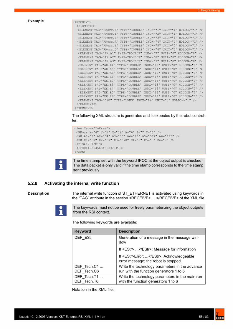
Issu
5. Programming
Example
The following XML structure is generated and is expected by the robot control-ler:
5.2.8 Activating the internal write function
Description The internal write function of ST_ETHERNET is activated using keywords in the “TAG” attribute in the section <RECEIVE> ... </RECEIVE> of the XML file.
The following keywords are available:
Notation in the XML file:
<RECEIVE> <ELEMENTS> <ELEMENT TAG="RKorr.X" TYPE="DOUBLE" INDX="1" UNIT="1" HOLDON="1" /> <ELEMENT TAG="RKorr.Y" TYPE="DOUBLE" INDX="2" UNIT="1" HOLDON="1" /> <ELEMENT TAG="RKorr.Z" TYPE="DOUBLE" INDX="3" UNIT="1" HOLDON="1" /> <ELEMENT TAG="RKorr.A" TYPE="DOUBLE" INDX="4" UNIT="0" HOLDON="1" /> <ELEMENT TAG="RKorr.B" TYPE="DOUBLE" INDX="5" UNIT="0" HOLDON="1" /> <ELEMENT TAG="RKorr.C" TYPE="DOUBLE" INDX="6" UNIT="0" HOLDON="1" /> <ELEMENT TAG="AK.A1" TYPE="DOUBLE" INDX="7" UNIT="0" HOLDON="0" /> <ELEMENT TAG="AK.A2" TYPE="DOUBLE" INDX="8" UNIT="0" HOLDON="0" /> <ELEMENT TAG="AK.A3" TYPE="DOUBLE" INDX="9" UNIT="0" HOLDON="0" /> <ELEMENT TAG="AK.A4" TYPE="DOUBLE" INDX="10" UNIT="0" HOLDON="0" /> <ELEMENT TAG="AK.A5" TYPE="DOUBLE" INDX="11" UNIT="0" HOLDON="0" /> <ELEMENT TAG="AK.A6" TYPE="DOUBLE" INDX="12" UNIT="0" HOLDON="0" /> <ELEMENT TAG="EK.E1" TYPE="DOUBLE" INDX="13" UNIT="0" HOLDON="0" /> <ELEMENT TAG="EK.E2" TYPE="DOUBLE" INDX="13" UNIT="0" HOLDON="0" /> <ELEMENT TAG="EK.E3" TYPE="DOUBLE" INDX="13" UNIT="0" HOLDON="0" /> <ELEMENT TAG="EK.E4" TYPE="DOUBLE" INDX="13" UNIT="0" HOLDON="0" /> <ELEMENT TAG="EK.E5" TYPE="DOUBLE" INDX="13" UNIT="0" HOLDON="0" /> <ELEMENT TAG="EK.E6" TYPE="DOUBLE" INDX="13" UNIT="0" HOLDON="0" /> <ELEMENT TAG="DiO" TYPE="LONG" INDX="19" UNIT="0" HOLDON="1" /> </ELEMENTS></RECEIVE>
<Sen Type="ImFree"> <RKorr X="4" Y="7" Z="32" A="6" B="" C="6" /> <AK A1="2" A2="54" A3="35" A4="76" A5="567" A6="785" /> <EK E1="67" E2="67" E3="678" E4="3" E5="3" E6="7" /> <DiO>123</DiO> <IPOC>123645634563</IPOC></Sen>
The time stamp set with the keyword IPOC at the object output is checked. The data packet is only valid if the time stamp corresponds to the time stamp sent previously.
The keywords must not be used for freely parameterizing the object outputs from the RSI context.
Keyword DescriptionDEF_EStr Generation of a message in the message win-
dow
If <EStr> ...</EStr>: Message for information
If <EStr>Error: ...</EStr>: Acknowledgeable error message; the robot is stopped.
DEF_Tech.C1 ... DEF_Tech.C6
Write the technology parameters in the advance run with the function generators 1 to 6
DEF_Tech.T1 ... DEF_Tech.T6
Write the technology parameters in the main run with the function generators 1 to 6
55 / 83ed: 10.12.2007 Version: KST Ethernet RSI XML 1.1 V1 en

KUKA.Ethernet RSI XML 1.1
If the write function is activated, the robot controller expects the following XML structure in the receive protocol:
Example
The following XML structure is generated and is expected by the robot control-ler:
Since the <EStr/> tag is empty, no message is generated. The data in the <RKorr .../> tag are available at the output of the RSI object ST_ETHERNET. The technology parameters are written directly to the controller.
5.2.9 Linking ST_ETHERNET in the RSI context
Description This function ensures that the parameters defined in the XML file in the “TAG” attribute correspond to the links defined in the KRL program.
(>>> 5.2.10 "Linking inputs" page 56)
(>>> 5.2.11 "Linking outputs" page 58)
5.2.10 Linking inputs
Syntax <Return_value>=ST_NEWLINK_IN(Object_ID, IDXOut, hEthernet, IDXIn, TAG)
<ELEMENT TAG="DEF_EStr" TYPE="STRING" INDX="INTERNAL" UNIT="0" /><ELEMENT TAG="DEF_Tech.C1" TYPE="FLOAT" INDX="INTERNAL" UNIT="0" />...<ELEMENT TAG="DEF_Tech.C6" TYPE="FLOAT" INDX="INTERNAL" UNIT="0" /><ELEMENT TAG="DEF_Tech.T1" TYPE="FLOAT" INDX="INTERNAL" UNIT="0" />...<ELEMENT TAG="DEF_Tech.T6" TYPE="FLOAT" INDX="INTERNAL" UNIT="0" />
<EStr>Message!</EStr><Tech T11="0.0" T12="0.0" T13="0.0" T14="0.0" T15="0.0" T16="0.0" T17="0.0" T18="0.0" T19="0.0" T110="0.0" />...<Tech T61="0.0" T62="0.0" T63="0.0" T64="0.0" T65="0.0" T66="0.0" T67="0.0" T68="0.0" T69="0.0" T610="0.0" /><Tech C11="0.0" C12="0.0" C13="0.0" C14="0.0" C15="0.0" C16="0.0" C17="0.0" C18="0.0" C19="0.0" C110="0.0" />...<Tech C51="0.0" C52="0.0" C53="0.0" C54="0.0" C55="0.0" C56="0.0" C57="0.0" C58="0.0" C59="0.0" C510="0.0" />
<RECEIVE> <ELEMENTS> <ELEMENT TAG="RKorr.X" TYPE="DOUBLE" INDX="1" UNIT="1" HOLDON="1" /> <ELEMENT TAG="RKorr.Y" TYPE="DOUBLE" INDX="2" UNIT="1" HOLDON="1" /> <ELEMENT TAG="RKorr.Z" TYPE="DOUBLE" INDX="3" UNIT="1" HOLDON="1" /> <ELEMENT TAG="DEF_EStr" TYPE="STRING" INDX="INTERNAL" UNIT="0" /> <ELEMENT TAG="DEF_Tech.C1" TYPE="FLOAT" INDX="INTERNAL" UNIT="0" /> </ELEMENTS></RECEIVE>
<Sen Type="ImFree"> <EStr/> <RKorr X="4" Y="7" Z="32" /> <Tech C11="0.0" C12="0.0" C13="0.0" C14="0.0" C15="0.0" C16="0.0" C17="0.0" C18="0.0" C19="0.0" C110="0.0" /> <IPOC>123645634563</IPOC></Sen>
With RSI objects with independent linking on creation of the object, this pro-cedure is not possible, e.g. ST_MAP_SEN_PREA
56 / 83 Issued: 10.12.2007 Version: KST Ethernet RSI XML 1.1 V1 en

Issu
5. Programming
Explanation of the syntax
Example In the XML file, object input 7 of ST_ETHERNET is defined.
In the corresponding KRL program, ST_ETHERNET is linked to the RSI ob-ject.
Instance parameter Description<Return_value> The return value contains the error code after an
RSI command has been executed.Object_ID INTEGER variable for the object ID in order to
access the RSI object to be assigned to the input of ST_ETHERNET.
The value of the variable is automatically assigned by the robot system when the RSI object is created.
IDXOut INTEGER variable for the output of the RSI object with the object ID, i.e. of the RSI object to be assigned to the input of ST_ETHERNET.
hEthernet INTEGER variable for the object ID in order to access the RSI object ST_ETHERNET.
IDXIn INTEGER variable for the input of the RSI object ST_ETHERNET that is to be linked to the output of the RSI object with the object ID.
TAG String defined in the XML file in the attribute “TAG”
...<SEND> <ELEMENTS>... <ELEMENT TAG="ST_SOURCE" TYPE="FLOAT" INDX="7" UNIT="3601" />... </ELEMENTS></SEND>
1 DEF Program( )2 DECL RSIERR RET3 INT hEthernet45 ...6 7 INI8 9 ...10 11 RET = ST_ETHERNET(hEthernet,0,"ERXconfig.xml")12 ...13 RET = ST_SOURCE(hsource,0,UNIT_RSI)14 RET = ST_NEWLINK_IN(hsource,1,hEthernet,7,"ST_Source")15 ...16 END
Line Description2 INTEGER variable for the return values3 INTEGER variable for the object ID11 Creation of the RSI object ST_ETHERNET13 Creation of the RSI object ST_SOURCE14 Linking of the signal from ST_SOURCE to ST_ETHERNET
57 / 83ed: 10.12.2007 Version: KST Ethernet RSI XML 1.1 V1 en

KUKA.Ethernet RSI XML 1.1
5.2.11 Linking outputs
Syntax <Return_value>=ST_NEWLINK_OUT(hEthernet, IDXOut, Objekt-ID, IDXIn, TAG)
Explanation of the syntax
Example In the XML file, object output 6 of ST_ETHERNET is defined.
In the corresponding KRL program, ST_ETHERNET is linked to the RSI ob-ject.
Instance parameter Description<Return_value> The return value contains the error code after an
RSI command has been executed.hEthernet INTEGER variable for the object ID in order to
access the RSI object ST_ETHERNET.IDXOut INTEGER variable for the output of the RSI
object ST_ETHERNETObject_ID INTEGER variable for the object ID in order to
access the RSI object to be assigned to the out-put of ST_ETHERNET.
The value of the variable is automatically assigned by the robot system when the RSI object is created.
IDXIn INTEGER variable for the input of the RSI object with the object ID, i.e. for the input to be linked to the output of ST_ETHERNET.
TAG String defined in the XML file in the attribute “TAG”
... <RECEIVE> <ELEMENTS> ... <ELEMENT TAG="RKorr.C" TYPE="DOUBLE" INDX="6" UNIT="0" HOLDON="1" /> ... </ELEMENTS> </RECEIVE>
1 DEF Program( )2 DECL RSIERR RET3 INT hEthernet45 ...6 7 INI8 9 ...10 11 RET = ST_ETHERNET(hEthernet,0,"ERXconfig.xml")12 ...13 RET = ST_PATHCORR(hPath,0)14 RET = ST_NEWLINK_OUT(hEthernet,6,hPath,3,"RKorr.C")15 ...16 END
Line Description2 INTEGER variable for the return values3 INTEGER variable for the object ID11 Creation of the RSI object ST_ETHERNET13 Creation of the RSI object ST_PATHCORR14 Linking of the signal from ST_ETHERNET to ST_PATHCORR
58 / 83 Issued: 10.12.2007 Version: KST Ethernet RSI XML 1.1 V1 en

Issu
6. Example
6 Example
6.1 Sample application
Description KUKA.Ethernet RSI XML includes a sample application that can be used to es-tablish communication between a server program and the robot controller. The software is located on the CD-ROM, in the EthernetRSIXML\Demo directory.
The application consists of the following components:
Server program Server_ERX.exeKRL program EKXDEmo.srcKRL program ERXDemo_1.srcConfiguration file ERXconfig.xmlSample source code in C#
6.2 Implementing the sample application
Procedure 1. Copy the contents of the EthernetRSIXML\Demo\Server_app directory to a Windows system with installed .NET Framework.
2. Copy the KRL programs ERXDemo and ERXDemo_1 in the directory Eth-ernetRSIXML\Demo\SRC_KRL\PROGRAM to the program directory of the robot controller.
3. Copy the XML file ERXconfig.xml in the directory Ethern-etRSIXML\Demo\SRC_KRL\INIT to the directory C:\KRC\ROBOTER\INIT of the robot controller.
4. Start the server program on the external system.5. Select the network adapter (NetcardIndex) to be used for communication.6. Set the network address of the external system.
For the KRL program ERXDemo.src, set the network address in the KRL program. (>>> 6.4 "KRL program ERXDemo.src" page 61)For the KRL program ERXDemo_1.src, set the network address in the configuration file ERXconfig.xml.
6.3 Server program Server_ERX.exe
The server program Server_ERX.exe makes it possible to test the connection between the external system and the robot controller by establishing perma-nent communication to the robot controller.
For this purpose, the received data are evaluated and the current interpolation cycle counter (the time stamp of the packet) is copied to the form that is to be sent. Depending on the setting in the KRL program ERXDemo.src or ERXDemo_1.src, the form can be sent with correction data from the “Moving” area or with zero values.
Functionalities:
The current version of Windows .NET Framework can be obtained free of charge from: http://www.microsoft.com/downloads/.
If no external system is available, communication can be carried out via the “Shared Memory” of the robot controller. In the server application, the net-work adapter (NetcardIndex) is set in such a way that the network address “192.0.1.2” is displayed.
59 / 83ed: 10.12.2007 Version: KST Ethernet RSI XML 1.1 V1 en
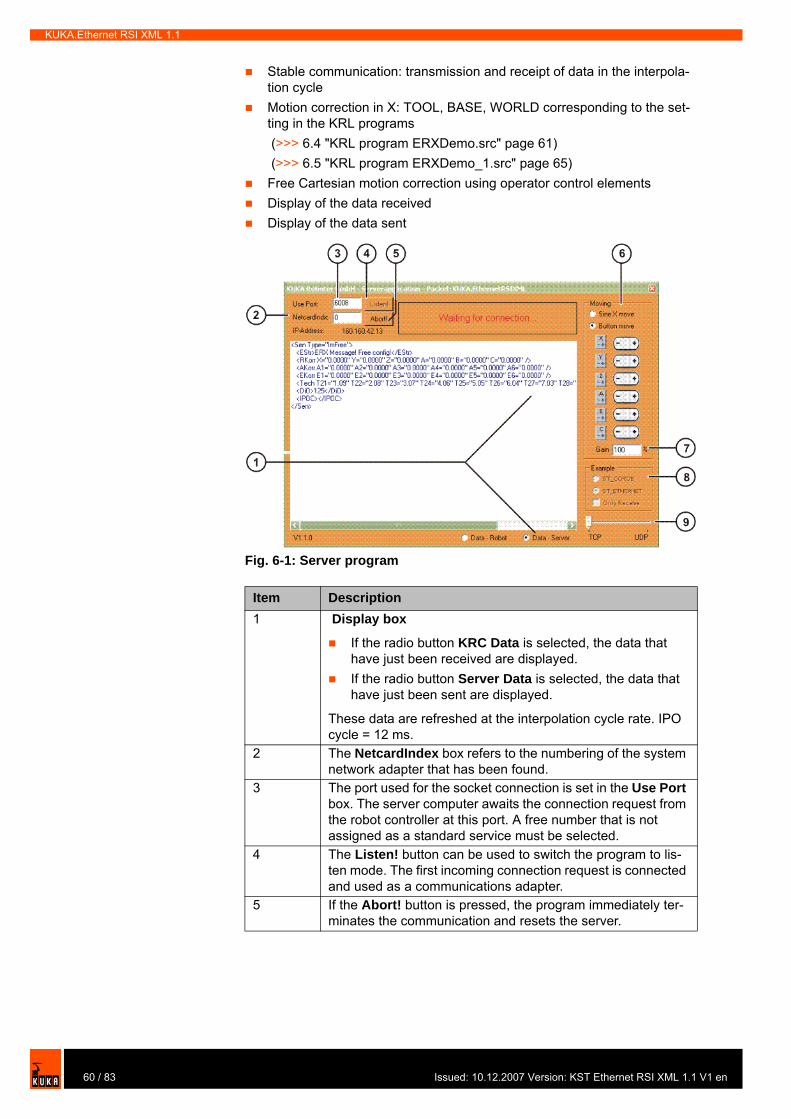
KUKA.Ethernet RSI XML 1.1
Stable communication: transmission and receipt of data in the interpola-tion cycleMotion correction in X: TOOL, BASE, WORLD corresponding to the set-ting in the KRL programs (>>> 6.4 "KRL program ERXDemo.src" page 61) (>>> 6.5 "KRL program ERXDemo_1.src" page 65)Free Cartesian motion correction using operator control elementsDisplay of the data receivedDisplay of the data sent
Fig. 6-1: Server program
Item Description1 Display box
If the radio button KRC Data is selected, the data that have just been received are displayed.If the radio button Server Data is selected, the data that have just been sent are displayed.
These data are refreshed at the interpolation cycle rate. IPO cycle = 12 ms.
2 The NetcardIndex box refers to the numbering of the system network adapter that has been found.
3 The port used for the socket connection is set in the Use Port box. The server computer awaits the connection request from the robot controller at this port. A free number that is not assigned as a standard service must be selected.
4 The Listen! button can be used to switch the program to lis-ten mode. The first incoming connection request is connected and used as a communications adapter.
5 If the Abort! button is pressed, the program immediately ter-minates the communication and resets the server.
60 / 83 Issued: 10.12.2007 Version: KST Ethernet RSI XML 1.1 V1 en
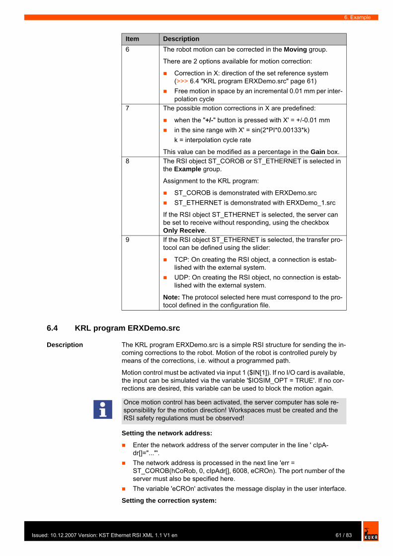
Issu
6. Example
6.4 KRL program ERXDemo.src
Description The KRL program ERXDemo.src is a simple RSI structure for sending the in-coming corrections to the robot. Motion of the robot is controlled purely by means of the corrections, i.e. without a programmed path.
Motion control must be activated via input 1 ($IN[1]). If no I/O card is available, the input can be simulated via the variable '$IOSIM_OPT = TRUE'. If no cor-rections are desired, this variable can be used to block the motion again.
Setting the network address:
Enter the network address of the server computer in the line ' cIpA-dr[]="..."'.The network address is processed in the next line 'err = ST_COROB(hCoRob, 0, cIpAdr[], 6008, eCROn). The port number of the server must also be specified here.The variable 'eCROn' activates the message display in the user interface.
Setting the correction system:
6 The robot motion can be corrected in the Moving group.
There are 2 options available for motion correction:
Correction in X: direction of the set reference system (>>> 6.4 "KRL program ERXDemo.src" page 61)Free motion in space by an incremental 0.01 mm per inter-polation cycle
7 The possible motion corrections in X are predefined:
when the "+/-" button is pressed with X' = +/-0.01 mmin the sine range with X' = sin(2*PI*0.00133*k) k = interpolation cycle rate
This value can be modified as a percentage in the Gain box.8 The RSI object ST_COROB or ST_ETHERNET is selected in
the Example group.
Assignment to the KRL program:
ST_COROB is demonstrated with ERXDemo.srcST_ETHERNET is demonstrated with ERXDemo_1.src
If the RSI object ST_ETHERNET is selected, the server can be set to receive without responding, using the checkbox Only Receive.
9 If the RSI object ST_ETHERNET is selected, the transfer pro-tocol can be defined using the slider:
TCP: On creating the RSI object, a connection is estab-lished with the external system.UDP: On creating the RSI object, no connection is estab-lished with the external system.
Note: The protocol selected here must correspond to the pro-tocol defined in the configuration file.
Item Description
Once motion control has been activated, the server computer has sole re-sponsibility for the motion direction! Workspaces must be created and the RSI safety regulations must be observed!
61 / 83ed: 10.12.2007 Version: KST Ethernet RSI XML 1.1 V1 en
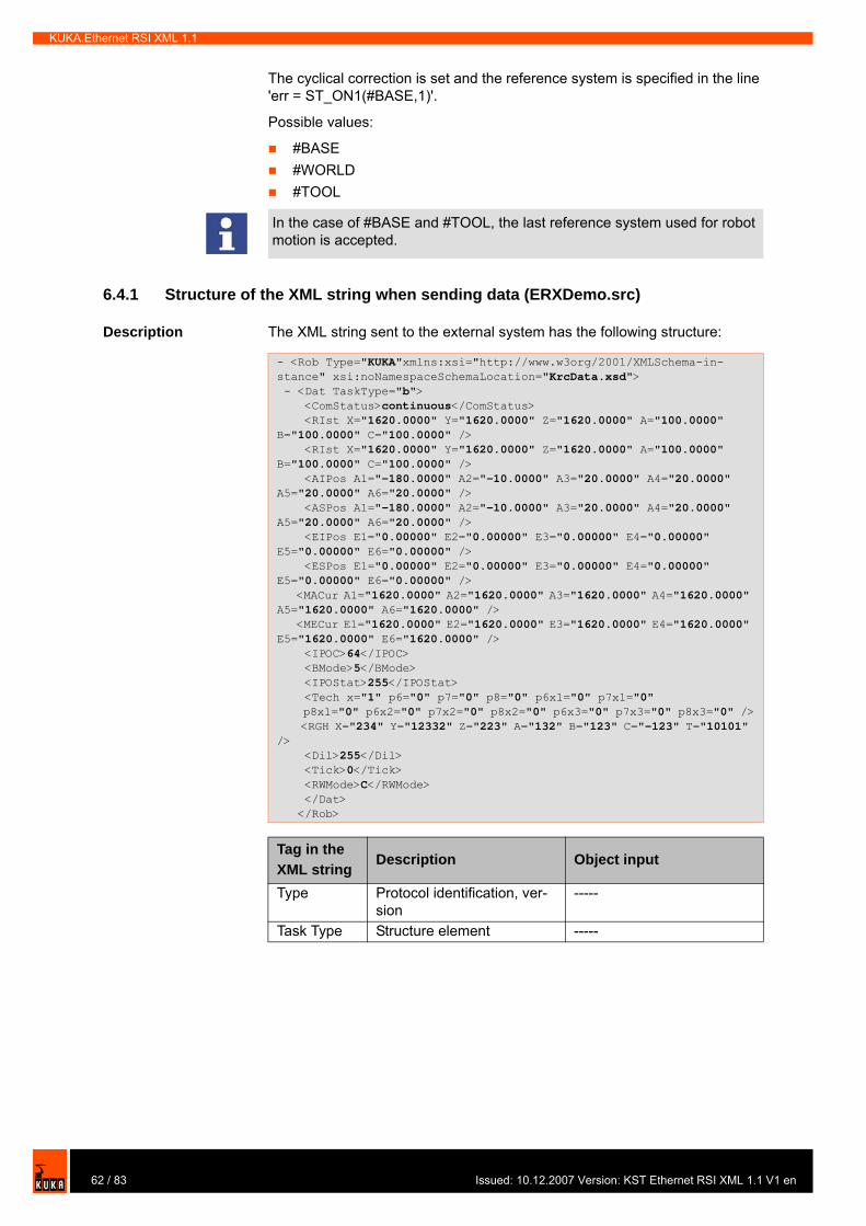
KUKA.Ethernet RSI XML 1.1
The cyclical correction is set and the reference system is specified in the line 'err = ST_ON1(#BASE,1)'.
Possible values:
#BASE#WORLD#TOOL
6.4.1 Structure of the XML string when sending data (ERXDemo.src)
Description The XML string sent to the external system has the following structure:
In the case of #BASE and #TOOL, the last reference system used for robot motion is accepted.
- <Rob Type="KUKA"xmlns:xsi="http://www.w3org/2001/XMLSchema-in-stance" xsi:noNamespaceSchemaLocation="KrcData.xsd"> - <Dat TaskType="b"> <ComStatus>continuous</ComStatus> <RIst X="1620.0000" Y="1620.0000" Z="1620.0000" A="100.0000" B="100.0000" C="100.0000" /> <RIst X="1620.0000" Y="1620.0000" Z="1620.0000" A="100.0000" B="100.0000" C="100.0000" /> <AIPos A1="-180.0000" A2="-10.0000" A3="20.0000" A4="20.0000" A5="20.0000" A6="20.0000" /> <ASPos A1="-180.0000" A2="-10.0000" A3="20.0000" A4="20.0000" A5="20.0000" A6="20.0000" /> <EIPos E1="0.00000" E2="0.00000" E3="0.00000" E4="0.00000" E5="0.00000" E6="0.00000" /> <ESPos E1="0.00000" E2="0.00000" E3="0.00000" E4="0.00000" E5="0.00000" E6="0.00000" /> <MACur A1="1620.0000" A2="1620.0000" A3="1620.0000" A4="1620.0000" A5="1620.0000" A6="1620.0000" /> <MECur E1="1620.0000" E2="1620.0000" E3="1620.0000" E4="1620.0000" E5="1620.0000" E6="1620.0000" /> <IPOC>64</IPOC> <BMode>5</BMode> <IPOStat>255</IPOStat> <Tech x="1" p6="0" p7="0" p8="0" p6x1="0" p7x1="0" p8x1="0" p6x2="0" p7x2="0" p8x2="0" p6x3="0" p7x3="0" p8x3="0" /> <RGH X="234" Y="12332" Z="223" A="132" B="123" C="-123" T="10101" /> <Dil>255</Dil> <Tick>0</Tick> <RWMode>C</RWMode> </Dat> </Rob>
Tag in the XML string
Description Object input
Type Protocol identification, ver-sion
-----
Task Type Structure element -----
62 / 83 Issued: 10.12.2007 Version: KST Ethernet RSI XML 1.1 V1 en
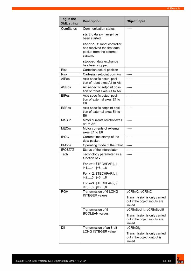
Issu
6. Example
ComStatus Communication status
start: data exchange has been started.
continous: robot controller has received the first data packet from the external system.
stopped: data exchange has been stopped.
-----
Rist Cartesian actual position -----Rsol Cartesian setpoint position -----AIPos Axis-specific actual posi-
tion of robot axes A1 to A6-----
ASPos Axis-specific setpoint posi-tion of robot axes A1 to A6
-----
EIPos Axis-specific actual posi-tion of external axes E1 to E6
-----
ESPos Axis-specific setpoint posi-tion of external axes E1 to E6
-----
MaCur Motor currents of robot axes A1 to A6
-----
MECur Motor currents of external axes E1 to E6
-----
IPOC Current time stamp of the data packet
-----
BMode Operating mode of the robot -----IPOSTAT Status of the interpolator -----Tech Technology parameter as a
function of x
For x=1: $TECHPAR[i, j], i=1,...,4 , j=6,...,8
For x=2: $TECHPAR[i, j], i=2,...,5 , j=6,...,8
For x=3: $TECHPAR[i, j], i=3,...,6 , j=6,...,8
-----
RGH Transmission of 6 LONG INTEGER values
eCRInX...eCRInC
Transmission is only carried out if the object inputs are linked
Transmission of 5 BOOLEAN values
eCRInBool1...eCRInBool5
Transmission is only carried out if the object inputs are linked
Dil Transmission of an 8-bit LONG INTEGER value
eCRInDig
Transmission is only carried out if the object output is linked
Tag in the XML string
Description Object input
63 / 83ed: 10.12.2007 Version: KST Ethernet RSI XML 1.1 V1 en

KUKA.Ethernet RSI XML 1.1
6.4.2 Structure of the XML string when importing data (ERXDemo.src)
Description The XML string imported from the external system has the following structure:
Tick Structure element -----RWMode Motion type and status of
the function generator-----
Tag in the XML string
Description Object input
- <Sen Type="CoRob" xmlns:xsi="http://www.w3org/2001/XMLSchema-in-stance" xsi:noNamespaceSchemaLocation="ExternalData.xsd"> - <Dat TaskType="b"> <Estr>Info: Nur zur Info</Estr> <RKorr X="0.1620 Y="0.1620 Y="0.1620 A="0.2000" B="0.2000" C="-0.2000" /> <AKorr A1="20.0000" A2="20.0000" A3="20.0000" A4="20.0000" A5="20.0000" A6="20.0000" /> <EKorr E1="120.0000" E2="120.0000" E3="120.0000" E4="120.0000" E5="120.0000" E6="120.0000" /> <Tech x="2" p3="0" p4="0" p5="0" p3x1="0" p4x1="0" p5x1="0" p3x2="0" p4x2="0" p5x2="0" p3x3="0" p4x3="0" p5x3="0" /> <DiO>255</DiO> <IPOC>64</IPOC> </Dat></Sen>
Tag in the XML string
Description Object output
Type Protocol identification, ver-sion
-----
TaskType Structure element -----Estr Generation of a message in
the message window
If <EStr>Info: ...</EStr>: Message for information
If <EStr>Error: ...</EStr>: Acknowledgeable error message; the robot is stopped.
Other messages are ignored.
-----
RKorr Importing of 6 DOUBLE val-ues for Cartesian correc-tions
eCROutX...eCROutC
AKorr Importing of 6 DOUBLE val-ues for axis-specific correc-tions of robot axes A1 to A6
eCROutA1...eCROutA6
EKorr Importing of 6 DOUBLE val-ues for axis-specific correc-tions of external axes E1 to E6
eCROutA7...eCROutA12
64 / 83 Issued: 10.12.2007 Version: KST Ethernet RSI XML 1.1 V1 en
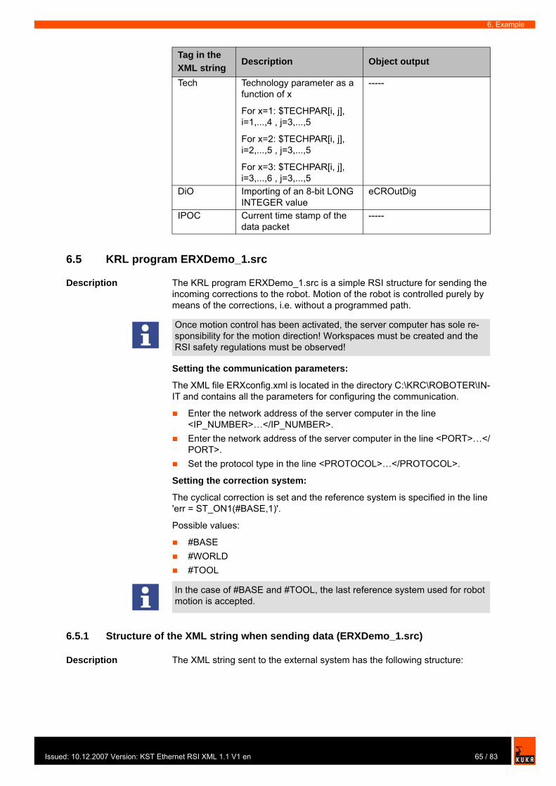
Issu
6. Example
6.5 KRL program ERXDemo_1.src
Description The KRL program ERXDemo_1.src is a simple RSI structure for sending the incoming corrections to the robot. Motion of the robot is controlled purely by means of the corrections, i.e. without a programmed path.
Setting the communication parameters:
The XML file ERXconfig.xml is located in the directory C:\KRC\ROBOTER\IN-IT and contains all the parameters for configuring the communication.
Enter the network address of the server computer in the line <IP_NUMBER>…</IP_NUMBER>.Enter the network address of the server computer in the line <PORT>…</PORT>.Set the protocol type in the line <PROTOCOL>…</PROTOCOL>.
Setting the correction system:
The cyclical correction is set and the reference system is specified in the line 'err = ST_ON1(#BASE,1)'.
Possible values:
#BASE#WORLD#TOOL
6.5.1 Structure of the XML string when sending data (ERXDemo_1.src)
Description The XML string sent to the external system has the following structure:
Tech Technology parameter as a function of x
For x=1: $TECHPAR[i, j], i=1,...,4 , j=3,...,5
For x=2: $TECHPAR[i, j], i=2,...,5 , j=3,...,5
For x=3: $TECHPAR[i, j], i=3,...,6 , j=3,...,5
-----
DiO Importing of an 8-bit LONG INTEGER value
eCROutDig
IPOC Current time stamp of the data packet
-----
Tag in the XML string
Description Object output
Once motion control has been activated, the server computer has sole re-sponsibility for the motion direction! Workspaces must be created and the RSI safety regulations must be observed!
In the case of #BASE and #TOOL, the last reference system used for robot motion is accepted.
65 / 83ed: 10.12.2007 Version: KST Ethernet RSI XML 1.1 V1 en
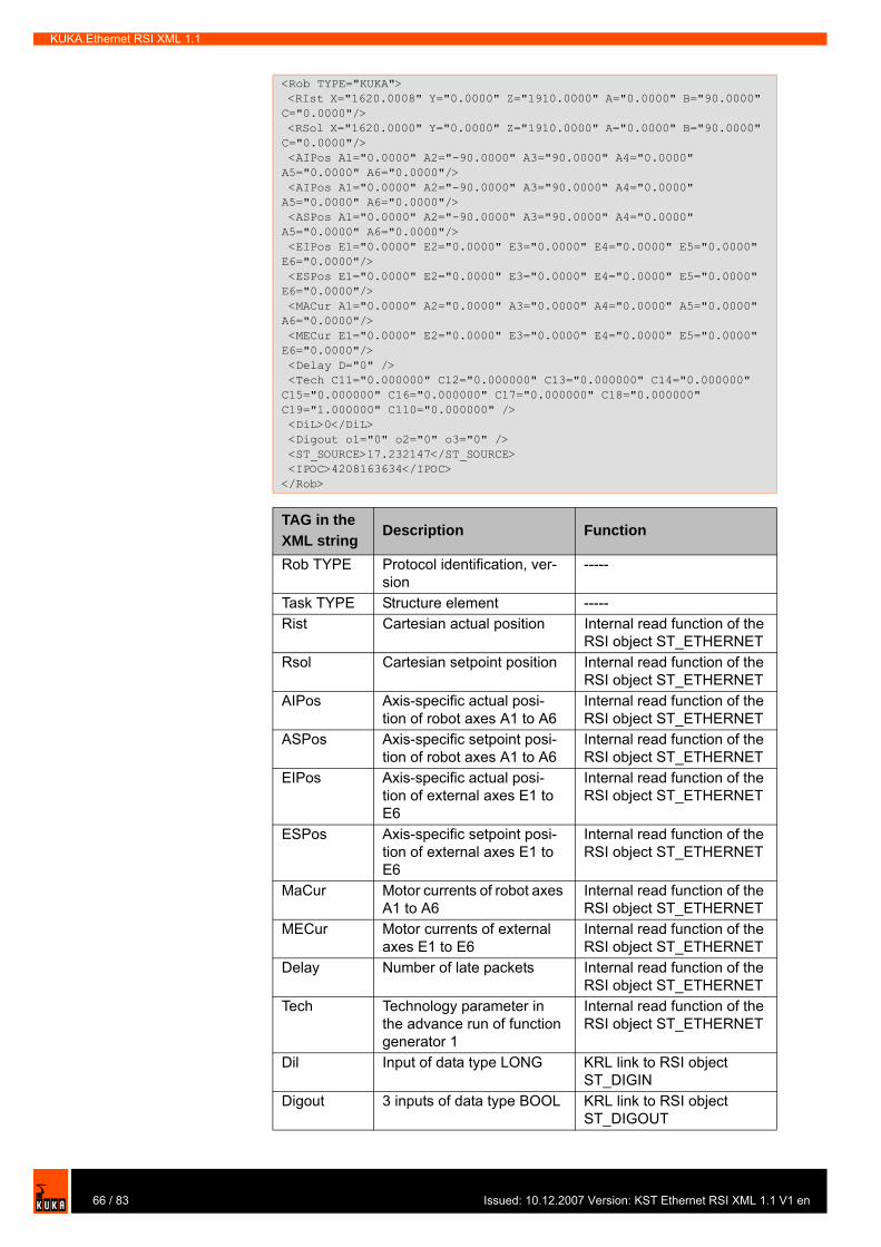
KUKA.Ethernet RSI XML 1.1
<Rob TYPE="KUKA"> <RIst X="1620.0008" Y="0.0000" Z="1910.0000" A="0.0000" B="90.0000" C="0.0000"/> <RSol X="1620.0000" Y="0.0000" Z="1910.0000" A="0.0000" B="90.0000" C="0.0000"/> <AIPos A1="0.0000" A2="-90.0000" A3="90.0000" A4="0.0000" A5="0.0000" A6="0.0000"/> <AIPos A1="0.0000" A2="-90.0000" A3="90.0000" A4="0.0000" A5="0.0000" A6="0.0000"/> <ASPos A1="0.0000" A2="-90.0000" A3="90.0000" A4="0.0000" A5="0.0000" A6="0.0000"/> <EIPos E1="0.0000" E2="0.0000" E3="0.0000" E4="0.0000" E5="0.0000" E6="0.0000"/> <ESPos E1="0.0000" E2="0.0000" E3="0.0000" E4="0.0000" E5="0.0000" E6="0.0000"/> <MACur A1="0.0000" A2="0.0000" A3="0.0000" A4="0.0000" A5="0.0000" A6="0.0000"/> <MECur E1="0.0000" E2="0.0000" E3="0.0000" E4="0.0000" E5="0.0000" E6="0.0000"/> <Delay D="0" /> <Tech C11="0.000000" C12="0.000000" C13="0.000000" C14="0.000000" C15="0.000000" C16="0.000000" C17="0.000000" C18="0.000000" C19="1.000000" C110="0.000000" /> <DiL>0</DiL> <Digout o1="0" o2="0" o3="0" /> <ST_SOURCE>17.232147</ST_SOURCE> <IPOC>4208163634</IPOC></Rob>
TAG in the XML string
Description Function
Rob TYPE Protocol identification, ver-sion
-----
Task TYPE Structure element -----Rist Cartesian actual position Internal read function of the
RSI object ST_ETHERNETRsol Cartesian setpoint position Internal read function of the
RSI object ST_ETHERNETAIPos Axis-specific actual posi-
tion of robot axes A1 to A6Internal read function of the RSI object ST_ETHERNET
ASPos Axis-specific setpoint posi-tion of robot axes A1 to A6
Internal read function of the RSI object ST_ETHERNET
EIPos Axis-specific actual posi-tion of external axes E1 to E6
Internal read function of the RSI object ST_ETHERNET
ESPos Axis-specific setpoint posi-tion of external axes E1 to E6
Internal read function of the RSI object ST_ETHERNET
MaCur Motor currents of robot axes A1 to A6
Internal read function of the RSI object ST_ETHERNET
MECur Motor currents of external axes E1 to E6
Internal read function of the RSI object ST_ETHERNET
Delay Number of late packets Internal read function of the RSI object ST_ETHERNET
Tech Technology parameter in the advance run of function generator 1
Internal read function of the RSI object ST_ETHERNET
Dil Input of data type LONG KRL link to RSI object ST_DIGIN
Digout 3 inputs of data type BOOL KRL link to RSI object ST_DIGOUT
66 / 83 Issued: 10.12.2007 Version: KST Ethernet RSI XML 1.1 V1 en

Issu
6. Example
The data set to be sent is generated automatically from the configuration file ERXconfig.xml. The object inputs of ST_ETHERNET are defined in this file:
6.5.2 Structure of the XML string when importing data (ERXDemo_1.src)
Description The XML string imported from the external system has the following structure:
ST_SOURCE
Input of data type FLOAT KRL link to RSI object ST_SOURCE
IPOC Current time stamp of the data packet
Internal function of the RSI object ST_ETHERNET
<SEND> <ELEMENTS> <ELEMENT TAG="DEF_RIst" TYPE="DOUBLE" INDX="INTERNAL" UNIT="0" /> <ELEMENT TAG="DEF_RSol" TYPE="DOUBLE" INDX="INTERNAL" UNIT="0" /> <ELEMENT TAG="DEF_AIPos" TYPE="DOUBLE" INDX="INTERNAL" UNIT="0" /> <ELEMENT TAG="DEF_ASPos" TYPE="DOUBLE" INDX="INTERNAL" UNIT="0" /> <ELEMENT TAG="DEF_EIPos" TYPE="DOUBLE" INDX="INTERNAL" UNIT="0" /> <ELEMENT TAG="DEF_ESPos" TYPE="DOUBLE" INDX="INTERNAL" UNIT="0" /> <ELEMENT TAG="DEF_MACur" TYPE="DOUBLE" INDX="INTERNAL" UNIT="0" /> <ELEMENT TAG="DEF_MECur" TYPE="DOUBLE" INDX="INTERNAL" UNIT="0" /> <ELEMENT TAG="DEF_Delay" TYPE="LONG" INDX="INTERNAL" UNIT="0" /> <ELEMENT TAG="DEF_Tech.C1" TYPE="FLOAT" INDX="INTERNAL" UNIT="0" /> <ELEMENT TAG="DiL" TYPE="LONG" INDX="1" UNIT="0" /> <ELEMENT TAG="Digout.o1" TYPE="BOOL" INDX="2" UNIT="0" /> <ELEMENT TAG="Digout.o2" TYPE="BOOL" INDX="3" UNIT="0" /> <ELEMENT TAG="Digout.o3" TYPE="BOOL" INDX="4" UNIT="0" /> <ELEMENT TAG="ST_Source" TYPE="FLOAT" INDX="5" UNIT="3601" /> <\ELEMENTS><\SEND>
TAG in the XML string
Description Function
<Sen Type="ImFree"> <EStr>ERX Message! Free config!</EStr> <RKorr X="0.0000" Y="0.0000" Z="0.0000" A="0.0000" B="0.0000" C="0.0000" /> <AKorr A1="0.0000" A2="0.0000" A3="0.0000" A4="0.0000" A5="0.0000" A6="0.0000" /> <EKorr E1="0.0000" E2="0.0000" E3="0.0000" E4="0.0000" E5="0.0000" E6="0.0000" /> <Tech T21="1.09" T22="2.08" T23="3.07" T24="4.06" T25="5.05" T26="6.04" T27="7.03" T28="8.02" T29="9.01" T210="10.00" /> <DiO>125</DiO> <IPOC></IPOC></Sen>
Tag in the XML string
Description Function
Sen Type Protocol identification -----Estr Generation of a message in
the message window
If <EStr> ...</EStr>: Mes-sage for information
If <EStr>Error: ...</EStr>: Acknowledgeable error message; the robot is stopped.
Internal write function of the RSI object ST_ETHERNET. No output exists.
67 / 83ed: 10.12.2007 Version: KST Ethernet RSI XML 1.1 V1 en

KUKA.Ethernet RSI XML 1.1
The data set received by the robot controller is assigned to the object outputs of ST_ETHERNET via the configuration in the file ERXconfig.xml.
RKorr Data field of data type DOU-BLE
Object output 1 ... 6 of ST_ETHERNET linked to the RSI objects ST_PATHCORR and ST_MAP2SEN_PREA. The values received are saved in $SEN_PREA [1 ... 6].
AKorr Data of data type DOUBLE Without link. Object outputs 7 ... 18 are not further proc-essed in the RSI context.
EKorr Data of data type DOUBLE Without link. Object outputs 7 ... 18 are not further proc-essed in the RSI context.
Tech Data of data type FLOAT Internal write function of the RSI object ST_ETHERNET. The values received are written in the main run to function generator 2.
DiO Data of data type LONG Object output 19 of ST_ETHERNET. This is linked in the KRL program to the RSI object ST_MAP2SEN_PINT. The data are saved in $SEN_PINT [1].
IPOC Current time stamp of the data packet
Internal function of the RSI object ST_ETHERNET
Tag in the XML string
Description Function
68 / 83 Issued: 10.12.2007 Version: KST Ethernet RSI XML 1.1 V1 en
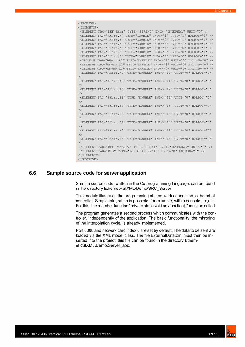
Issu
6. Example
6.6 Sample source code for server application
Sample source code, written in the C# programming language, can be found in the directory EthernetRSIXML\Demo\SRC_Server.
This module illustrates the programming of a network connection to the robot controller. Simple integration is possible, for example, with a console project. For this, the member function "private static void anyfunction()" must be called.
The program generates a second process which communicates with the con-troller, independently of the application. The basic functionality, the mirroring of the interpolation cycle, is already implemented.
Port 6008 and network card index 0 are set by default. The data to be sent are loaded via the XML model class. The file ExternalData.xml must then be in-serted into the project; this file can be found in the directory Ethern-etRSIXML\Demo\Server_app.
<RECEIVE><ELEMENTS> <ELEMENT TAG="DEF_EStr" TYPE="STRING" INDX="INTERNAL" UNIT="0" /> <ELEMENT TAG="RKorr.X" TYPE="DOUBLE" INDX="1" UNIT="1" HOLDON="1" /> <ELEMENT TAG="RKorr.Y" TYPE="DOUBLE" INDX="2" UNIT="1" HOLDON="1" /> <ELEMENT TAG="RKorr.Z" TYPE="DOUBLE" INDX="3" UNIT="1" HOLDON="1" /> <ELEMENT TAG="RKorr.A" TYPE="DOUBLE" INDX="4" UNIT="0" HOLDON="1" /> <ELEMENT TAG="RKorr.B" TYPE="DOUBLE" INDX="5" UNIT="0" HOLDON="1" /> <ELEMENT TAG="RKorr.C" TYPE="DOUBLE" INDX="6" UNIT="0" HOLDON="1" /> <ELEMENT TAG="AKorr.A1" TYPE="DOUBLE" INDX="7" UNIT="0" HOLDON="0" /> <ELEMENT TAG="AKorr.A2" TYPE="DOUBLE" INDX="8" UNIT="0" HOLDON="0" /> <ELEMENT TAG="AKorr.A3" TYPE="DOUBLE" INDX="9" UNIT="0" HOLDON="0" /> <ELEMENT TAG="AKorr.A4" TYPE="DOUBLE" INDX="10" UNIT="0" HOLDON="0" /> <ELEMENT TAG="AKorr.A5" TYPE="DOUBLE" INDX="11" UNIT="0" HOLDON="0" /> <ELEMENT TAG="AKorr.A6" TYPE="DOUBLE" INDX="12" UNIT="0" HOLDON="0" /> <ELEMENT TAG="EKorr.E1" TYPE="DOUBLE" INDX="13" UNIT="0" HOLDON="0" /> <ELEMENT TAG="EKorr.E2" TYPE="DOUBLE" INDX="13" UNIT="0" HOLDON="0" /> <ELEMENT TAG="EKorr.E3" TYPE="DOUBLE" INDX="13" UNIT="0" HOLDON="0" /> <ELEMENT TAG="EKorr.E4" TYPE="DOUBLE" INDX="13" UNIT="0" HOLDON="0" /> <ELEMENT TAG="EKorr.E5" TYPE="DOUBLE" INDX="13" UNIT="0" HOLDON="0" /> <ELEMENT TAG="EKorr.E6" TYPE="DOUBLE" INDX="13" UNIT="0" HOLDON="0" /> <ELEMENT TAG="DEF_Tech.T2" TYPE="FLOAT" INDX="INTERNAL" UNIT="0" /> <ELEMENT TAG="DiO" TYPE="LONG" INDX="19" UNIT="0" HOLDON="1" /><\ELEMENTS><\RECEIVE>
69 / 83ed: 10.12.2007 Version: KST Ethernet RSI XML 1.1 V1 en

KUKA.Ethernet RSI XML 1.1
70 / 83 Issued: 10.12.2007 Version: KST Ethernet RSI XML 1.1 V1 en

Issu
7. Diagnosis
7 Diagnosis
7.1 Diagnosis with Telnet
Description Telnet can be used to check the configuration and communication with Vx-Works.
Procedure 1. Click on the Windows Start button.2. Select the menu option Run....3. In the Open box, enter the command telnetk 192.0.1.1 and press OK. The
Telnet window is opened.
Displaying the IP address
The IP address can be checked using the version command. The address is displayed in the "Boot line" under e=....
Testing the network card
The command ping xxx.xxx.xxx.xxx can be used to check the communica-tion of the VxWorks system network card with the remote station. The com-mand can be aborted by closing the Telnet window.
Connection present:
No connection:
It is only possible to display the IP address with Telnet if using KUKA System Software (KSS) 5.x.
-> versionVxWorks (for VxWin RTAcc) version 5.4.2.Kernel: WIND version 2.5.Made on Mar 7 2005, 11:13:54.Boot line:esmc(0,1)pc:vxworks h=192.0.1.2 b=192.0.1.1 e=160.160.62.118 u=target pw=vxworksvalue = 92 = 0x5c = '\'
-> ping "192.0.1.2"PING 192.0.1.2: 56 data bytes64 bytes from pc (192.0.1.2): icmp_seq=0. time=0. ms64 bytes from pc (192.0.1.2): icmp_seq=1. time=0. ms64 bytes from pc (192.0.1.2): icmp_seq=2. time=0. ms64 bytes from pc (192.0.1.2): icmp_seq=3. time=0. ms...
-> ping "123.123.45.2"PING 123.123.45.2: 56 data bytesno answer from 123.123.45.2
71 / 83ed: 10.12.2007 Version: KST Ethernet RSI XML 1.1 V1 en

KUKA.Ethernet RSI XML 1.1
72 / 83 Issued: 10.12.2007 Version: KST Ethernet RSI XML 1.1 V1 en
Issu
8. KUKA Service
8 KUKA Service
8.1 Requesting support
Introduction The KUKA Robot Group documentation offers information on operation and provides assistance with troubleshooting. For further assistance, please con-tact your local KUKA subsidiary.
Information The following information is required for processing a support request:
Model and serial number of the robotModel and serial number of the controllerModel and serial number of the linear unit (if applicable)Version of the KUKA System SoftwareOptional software or modificationsArchive of the softwareApplication usedAny external axes usedDescription of the problem, duration and frequency of the fault
8.2 KUKA Customer Support
Availability KUKA Customer Support is available in many countries. Please do not hesi-tate to contact us if you have any questions.
Argentina Ruben Costantini S.A. (Agency)Luis Angel Huergo 13 20Parque Industrial2400 San Francisco (CBA)ArgentinaTel. +54 3564 421033Fax +54 3564 [email protected]
Australia Marand Precision Engineering Pty. Ltd. (Agency)153 Keys RoadMoorabbinVictoria 31 89AustraliaTel. +61 3 8552-0600Fax +61 3 [email protected]
Faults leading to production downtime are to be reported to the local KUKA subsidiary within one hour of their occurrence.
73 / 83ed: 10.12.2007 Version: KST Ethernet RSI XML 1.1 V1 en
KUKA.Ethernet RSI XML 1.1
Austria KUKA Roboter GmbHVertriebsbüro ÖsterreichRegensburger Strasse 9/14020 LinzAustriaTel. +43 732 784752Fax +43 732 [email protected]
Belgium KUKA Automatisering + Robots N.V.Centrum Zuid 10313530 HouthalenBelgiumTel. +32 11 516160Fax +32 11 [email protected]
Brazil KUKA Roboter do Brasil Ltda.Avenida Franz Liszt, 80Parque Novo MundoJd. GuançãCEP 02151 900 São PauloSP BrazilTel. +55 11 69844900Fax +55 11 [email protected]
Chile Robotec S.A. (Agency)Santiago de ChileChileTel. +56 2 331-5951Fax +56 2 [email protected]
China KUKA Flexible Manufacturing Equipment (Shanghai) Co., Ltd.Shanghai Qingpu Industrial ZoneNo. 502 Tianying Rd.201712 ShanghaiP.R. ChinaTel. +86 21 5922-8652Fax +86 21 [email protected]
74 / 83 Issued: 10.12.2007 Version: KST Ethernet RSI XML 1.1 V1 en
Issu
8. KUKA Service
France KUKA Automatisme + Robotique SASTechvallée6 Avenue du Parc91140 Villebon s/YvetteFranceTel. +33 1 6931-6600Fax +33 1 [email protected]
Germany KUKA Roboter GmbHBlücherstr. 14486165 AugsburgGermanyTel. +49 821 797-4000Fax +49 821 [email protected]
Hungary KUKA Robotics Hungaria Kft.Fö út 1402335 TaksonyHungaryTel. +36 24 501609Fax +36 24 [email protected]
India KUKA Robotics, Private Limited621 Galleria TowersDLF Phase IV122 002 GurgaonHaryanaIndiaTel. +91 124 [email protected]
Italy KUKA Roboter Italia S.p.A.Via Pavia 9/a - int.610098 Rivoli (TO)ItalyTel. +39 011 959-5013Fax +39 011 [email protected]
75 / 83ed: 10.12.2007 Version: KST Ethernet RSI XML 1.1 V1 en
KUKA.Ethernet RSI XML 1.1
Korea KUKA Robot Automation Korea Co. Ltd.4 Ba 806 Sihwa Ind. ComplexSung-Gok Dong, Ansan CityKyunggi Do425-110KoreaTel. +82 31 496-9937 or -9938Fax +82 31 [email protected]
Malaysia KUKA Robot Automation Sdn BhdSouth East Asia Regional OfficeNo. 24, Jalan TPP 1/10Taman Industri Puchong47100 PuchongSelangorMalaysiaTel. +60 3 8061-0613 or -0614Fax +60 3 [email protected]
Mexico KUKA de Mexico S. de R.L. de C.V.Rio San Joaquin #339, Local 5Colonia Pensil SurC.P. 11490 Mexico D.F.MexicoTel. +52 55 5203-8407Fax +52 55 [email protected]
Norway KUKA Sveiseanlegg + RoboterBryggeveien 92821 GjövikNorwayTel. +47 61 133422Fax +47 61 [email protected]
Portugal KUKA Sistemas de Automatización S.A.Rua do Alto da Guerra n° 50Armazém 042910 011 SetúbalPortugalTel. +351 265 729780Fax +351 265 [email protected]
76 / 83 Issued: 10.12.2007 Version: KST Ethernet RSI XML 1.1 V1 en
Issu
8. KUKA Service
Russia KUKA-VAZ EngineeringJushnoje Chaussee, 36 VAZ, PTO445633 TogliattiRussiaTel. +7 8482 391249 or 370564Fax +7 8482 [email protected]
South Africa Jendamark Automation LTD (Agency)76a York RoadNorth End6000 Port ElizabethSouth AfricaTel. +27 41 391 4700Fax +27 41 373 3869www.jendamark.co.za
Spain KUKA Sistemas de Automatización S.A.Pol. IndustrialTorrent de la PasteraCarrer del Bages s/n08800 Vilanova i la Geltrú (Barcelona)SpainTel. +34 93 814-2353Fax +34 93 [email protected]
Sweden KUKA Svetsanläggningar + Robotar ABA. Odhners gata 15421 30 Västra FrölundaSwedenTel. +46 31 7266-200Fax +46 31 [email protected]
Switzerland KUKA Roboter Schweiz AGRiedstr. 78953 DietikonSwitzerlandTel. +41 44 74490-90Fax +41 44 [email protected]
77 / 83ed: 10.12.2007 Version: KST Ethernet RSI XML 1.1 V1 en
KUKA.Ethernet RSI XML 1.1
Taiwan KUKA Robot Automation Taiwan Co. Ltd.136, Section 2, Huanjung E. RoadJungli City, TaoyuanTaiwan 320Tel. +886 3 4371902Fax +886 3 [email protected]
Thailand KUKA Robot Automation (M)SdnBhdThailand Officec/o Maccall System Co. Ltd.49/9-10 Soi Kingkaew 30 Kingkaew RoadTt. Rachatheva, A. BangpliSamutprakarn10540 ThailandTel. +66 2 7502737Fax +66 2 [email protected]
UK KUKA Automation + RoboticsHereward RiseHalesowenB62 8ANUKTel. +44 121 585-0800Fax +44 121 [email protected]
USA KUKA Robotics Corp.22500 Key DriveClinton Township48036 MichiganUSATel. +1 866 8735852Fax +1 586 [email protected]
78 / 83 Issued: 10.12.2007 Version: KST Ethernet RSI XML 1.1 V1 en

Issu
Index
Index
Numbers73/23/EEC 3289/336/EEC 3297/23/EC 3298/37/EC 32
AAccessories 15Applied norms and regulations 32Areas of application 9AUT 18, 19AUT EXT 19Automatic 18, 19Automatic External 19Automatic mode 30Axis range 15Axis range limitation 25Axis range monitoring 25
BBrake defect 27Braking distance 15, 22Braking, path-maintaining 16, 21Braking, path-oriented 16, 21
CCE mark 14Characteristics 9Cleaning work 30Communication 9Communication parameters, setting 65Communication parameters, ST_ETHERNET 50Configuration file, definition 49Connecting cables 14Connection for external enabling switch 23Correction system, setting 61, 65Counterbalancing system 31
DDanger zone 15Declaration of conformity 14Declaration of incorporation 13, 14Decommissioning 31Designated use 14Diagnosis 71Disposal 31Documentation, robot system 7Drives OFF 18Drives ON 18
EEC declaration of conformity 14EMC Directive 14, 32EMERGENCY STOP 20, 26EMERGENCY STOP button 22, 23, 24EMERGENCY STOP function 30EN 418 32
EN 55011 32EN 563 32EN 60204-1 32EN 61000-4-4 32EN 61000-4-5 33EN 61000-6-2 33EN 61000-6-4 33EN 614-1 32EN 61800-3 33EN 775 32EN 954-1 32EN ISO 10218-1 33EN ISO 12100-1 33EN ISO 12100-2 33Enabling 18Enabling switches 23, 24ERXDemo.src 61ERXDemo_1.src 65ESC 18Ethernet 8Example 59External axes 15External axis 16External EMERGENCY STOP 18External safeguards 26
FFaults 27Firewall 29Function test 28Functions 9
GGeneral safety measures 27Guard interlock 22
HHazardous substances 31
IInputs, linking 56Installation 35Installation, KUKA.Ethernet RSI XML 36Instance parameters, ST_COROB 39, 40Instance parameters, ST_ETHERNET 45, 46Introduction 7IP address, displaying 71IP address, modifying 37
JJog mode 24
KKCP 14, 15, 27KCP coupler 25Keyboard, external 27KRL program, ERXDemo.src 61
79 / 83ed: 10.12.2007 Version: KST Ethernet RSI XML 1.1 V1 en
KUKA.Ethernet RSI XML 1.1
KRL program, ERXDemo_1.src 65KUKA Customer Support 73
LLabeling 26Liability 13Linear unit 15Local EMERGENCY STOP 18Low Voltage Directive 14, 32
MMachinery Directive 14, 32Maintenance 30Manual High Velocity 18, 19Manual Reduced Velocity 18, 19Mechanical axis range limitation 25Mechanical end stops 24Mode selector switch 18, 19Mouse, external 27
NNetwork address, setting 61Network security 29
OObject ID 8Object inputs, ST_COROB 42Object inputs, ST_ETHERNET 51Object outputs, ST_COROB 43Object outputs, ST_ETHERNET 54Object parameters 8Object parameters, ST_COROB 39, 41Object parameters, ST_ETHERNET 46, 48Operating modes 18, 24Operator 17Operator safety 18, 22, 24Options 15Outputs, linking 58Overload 27Overview of the safety features 18Overview, KUKA.Ethernet RSI XML 9
PPanic position 23, 24Parser 8Path-maintaining 16, 21Path-oriented 21path-oriented 16PCI slot assignment 35Personnel 16Ping 71Positioner 15Pressure Equipment Directive 31, 32Preventive maintenance work 30Product description 9Programming 29, 39
RRamp-down braking 16, 21Read function, activating 52
Reduced velocity, program mode 24Reinstallation, KUKA.Ethernet RSI XML 37Release device 25Repair 30Required knowledge and skills 7Robot 14, 22Robot controller 14, 29Robot system 13, 14, 16RSI context 8RSI object 8RSI object, ST_COROB 39RSI object, ST_ETHERNET 45
SSafety 13Safety features 24Safety fences 26Safety gates 26Safety instructions 7, 13Safety logic 18Safety zone 16, 21, 22Safety, general 13Sample application 59Sample application, implementing 59Sample source code 69Server application 69Server program, Server_ERX.exe 59Server_ERX.exe 59Service, KUKA Roboter 73Setting 29Short-circuit braking 21Simulation 29Software 15Software limit switches 24ST_COROB, configuring 41ST_COROB, creating 40ST_COROB, object inputs 42ST_COROB, object outputs 43ST_ETHERNET, configuring 47ST_ETHERNET, creating 46ST_ETHERNET, linking 56ST_ETHERNET, object inputs 51ST_ETHERNET, object outputs 54Start-up 28STOP 0 16, 20STOP 1 16, 20STOP 2 16, 20Stop reactions 20Storage 31Structure, XML string, ERXDemo.src 62, 64Structure, XML string, ERXDemo_1.src 65, 67Support request 73System integrator 14, 16, 17System requirements 35
TT1 16, 18, 19T2 16, 18, 19Target group 7TCP/IP 8
80 / 83 Issued: 10.12.2007 Version: KST Ethernet RSI XML 1.1 V1 en
Issu
Index
Teach pendant 14Telnet, diagnosis 71Terms 8, 15Terms used 8, 15Testing the network card, VxWorks 71Top-mounted cabinet 15Trademarks 7Training program 7, 17Transport position 28Transportation 28Two-axis positioner 15
UUDP/IP 8Uninstallation, KUKA.Ethernet RSI XML 37Use, contrary to designated use 13Use, improper 13User 15, 16
VVirus protection 29
WWarnings 7, 13Working range limitation 25Workspace 15, 21, 22Write function, activating 55
XXML 8XML string, structure, ERXDemo.src 62, 64XML string, structure, ERXDemo_1.src 65, 67
81 / 83ed: 10.12.2007 Version: KST Ethernet RSI XML 1.1 V1 en

KUKA.Ethernet RSI XML 1.1
82 / 83 Issued: 10.12.2007 Version: KST Ethernet RSI XML 1.1 V1 en

83 / 83Issued: 10.12.2007 Version: KST Ethernet RSI XML 1.1 V1 en