kti75146 owners manual - toolweb · ktp75146ds drawer slides/one pair ... • máxima capacidad de...
TRANSCRIPT
KTI75146 1 rev. 08/04/14
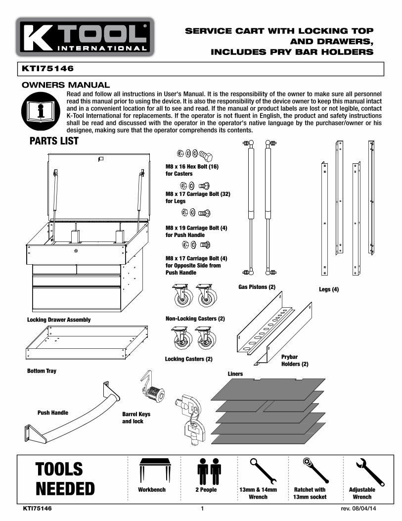
PARTS LIST
Locking Casters (2)
Non-Locking Casters (2)
M8 x 16 Hex Bolt (16)for Casters
M8 x 17 Carriage Bolt (32)for Legs
M8 x 17 Carriage Bolt (4)for Opposite Side from Push Handle
M8 x 19 Carriage Bolt (4)for Push Handle
Locking Drawer Assembly
Bottom Tray
Push Handle Barrel Keysand lock
Legs (4)Gas Pistons (2)
Prybar Holders (2)
Liners
Workbench 2 People 13mm & 14mm Wrench
Ratchet with 13mm socket
Adjustable Wrench
TOOLS NEEDED
Read and follow all instructions in User's Manual. It is the responsibility of the owner to make sure all personnel read this manual prior to using the device. It is also the responsibility of the device owner to keep this manual intact and in a convenient location for all to see and read. If the manual or product labels are lost or not legible, contact K-Tool International for replacements. If the operator is not fluent in English, the product and safety instructions shall be read and discussed with the operator in the operator's native language by the purchaser/owner or his designee, making sure that the operator comprehends its contents.
OWNERS MANUAL
Service cart with Locking top and drawerS,
incLudeS pry Bar hoLderS
KTI75146

KTI75146 2 rev. 08/04/14
ASSEMBLY INSTRUCTIONS
CAUTION
NOTE
NOTE
NOTE
Step 1: Assembly PreparationRemove all contents from box. Reference the parts list to make sure you have all the parts.
Verify your workbench can support 150 lbs. (68 kg.). Failure to follow this warning could result in damage to property or personal injury.
Cover workbench to prevent any damage to surface.
Step 2: Pry Bar HoldersLay two legs down on the table top and attach pry bar holder as shown in figure 2. Repeat with other two legs and pry bar holder. NOTE: Legs are marked with UP label to indicate which side is up.
Step 3: Attaching CastersTurn bottom tray upside down. Align holes in locking and non-locking casters with matching holes in the bottom tray as shown in figure 3a. Attach using M8 Hex bolts, lock washers and nuts from caster bolt kit and hand tighten.
Ensure that both locking casters are on same end of the cart. We suggest same side as handle.
Before moving to step 4 place a covering on the floor (to protect the cart) and finish assembly on the floor.
Step 4: Aligning the LegsMake sure the drawer assembly lid is open. Place legs and attached pry bar holders onto drawer assembly and bottom of tray as shown in figure 4. Repeat on opposite side of service cart. Hand tighten so all holes will line up.
4.
2.
3.
3a.
B
A
B
A

KTI75146 3 rev. 08/04/14
ASSEMBLY INSTRUCTIONS
Step 5: Attaching Bottom Tray and Drawer Assembly to Legs
Align holes in legs with matching holes in bottom tray and drawer assembly as shown in figure 5. Insert bolts through legs and into bottom tray and/or drawer assembly and secure from the inside with leg washers and nuts until all side holes have been attached and hand tightened.
Step 6: Attaching the Handle
(A) Align the other legs with the front corners of the bottom tray and drawer assembly. Align the hole on the handle with the second hole down on the drawer assembly and (unattached) leg as shown in figure 6. Insert M8 x 19 handle bolts through handle, through the legs and into the drawer assembly as shown in figure 6. Secure with washer and nut from handle bolt kit and hand tighten.
(B) Attach remaining M8 x 17 bolts (on the opposite side from push handle) directly into legs.
Step 7: Securing Legs
Using two people, turn the cart upright. Continue to bolt through aligned holes in the front and back of the cart with the M8 x 17 bolts, washers, and nuts as shown in figure 7. Hand tighten. ALL holes should now be aligned and secured.
Step 8: Tightening Bolts (not shown)
Use a 13mm wrench or a ratchet with 13mm socket or adjustable wrench to tighten all bolts. Be sure to apply pressure to bolt head while tightening to keep in correct position. Once all bolts are tightened, your cart is complete. See page 4 for parts breakdown.
5.
6.
7.
KTI75146 4 rev. 08/04/14
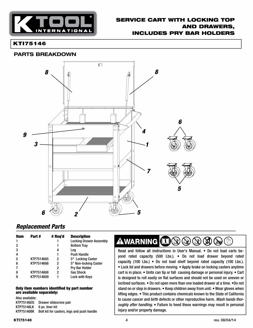
Item Part # # Req’d Description1 1 Locking Drawer Assembly2 1 Bottom Tray3 4 Leg4 1 Push Handle5 KTP7514605 2 5" Locking Caster6 KTP7514606 2 5" Non-locking Caster7 2 Pry Bar Holder8 KTP7514608 2 Gas Shock9 KTP7514609 1 Lock with Keys
Only item numbers identified by part number are available separately:Also available:KTP75146DS Drawer slides/one pairKTP75146LK 6 pc. liner kitKTP75146BK Bolt kit for casters, legs and push handle
Replacement Parts
1
9
8 8
7
5
4
526
3
6
Read and follow all instructions in User's Manual. • Do not load carts be-yond rated capacity (500 Lbs.). • Do not load drawer beyond rated capacity (100 Lbs.) • Do not load shelf beyond rated capacity (100 Lbs.). • Lock lid and drawers before moving. • Apply brake on locking casters anytime cart is in place. • Units can tip or fall causing damage or personal injury. • Cart is designed to roll easily on flat surfaces and should not be used on uneven or inclined surfaces. • Do not open more than one loaded drawer at a time. •Do not stand on or step in drawers. • Keep children away from unit. • Wear gloves when lifting edges. • This product contains chemicals known to the State of California to cause cancer and birth defects or other reproductive harm. Wash hands thor-oughly after handling. • Failure to heed these warnings may result in personal injury and/or property damage.
WARNING
Service cart with Locking top and drawerS,
incLudeS pry Bar hoLderS
pARtS bREAkdOWN
KTI75146

KTI75146 5 rev. 08/04/14
LISTA DE PARTES
HERRAMIENTASNECESARIAS
Lea y comprenda todas las instrucciones. Hacer caso omiso al seguir todas las instrucciones alistadas a continuación podría ocasionar el choque eléctrico, incendio, explosiones y/o lesiones personales serias. Es las responsabilidad del propietario asegurarse que todo el personal lea este manual previo al uso de este dispositivo. También es la responsabilidad del propietario del dispositivo mantener intacto este manual y en un lugar conveniente para que todos lo lean y vean. Si el manual o las etiquetas se hayan perdido o no sean legibles, comuníquese con K-Tool International por algunos repuestos. Si el operador no domina el idioma inglés, las instruc-ciones del producto y de seguridad le serán leídas y discutidas con el operador en el idioma materno del operador por parte del comprador/propietario o su designado, asegurándose que el operador comprenda el contenido.
Rodajas de seguridad (2)
Rodajas sin auto-cierre (2)
Pernos hexagonales (16) M8 x 16 para rodajas
Perno de carrocería (32) M8 x 17 x para patas
Perno de carrocería (4) M8 x 19 (4) para manija de empuje
Ensamble de cajón de seguridad
Charola inferior
Cerradura y llaves de tubo
Patas (4)Pistones de gas (2)
Sujetadores de la barra de palanca (2)
Forros
Banco de trabajo 2 personas Llave 13mm y 14mm
Trinquete con casquillo 13mm
Llave ajustable
Perno de carrocería (4) M8 x 17 para el lado opuesto de lamanija de empuje
Manija de empuje
carrito de Servicio con parte Superior y cajoneS de Seguridad
y incLuye SujetadoreS de Barra de paLanca
KTI75146

KTI75146 6 rev. 08/04/14
INSTRUCCIONES DE ENSAMBLE
4.
2.
3.
3a.
B
A
B
APaso 1: Preparación de ensambleExtraiga todo el contenido de la caja. Consulte la lista de partes para asegurarse que cuente con todas las partes.
Verifique que su banco de trabajo pueda soportar 150 libras. (68 kg.). Hacer caso omiso a esta advertencia podrá ocasionar daños a la propiedad o lesiones personales.
Cubra el banco de trabajo con el fin de prevenir cualquier daño a la superficie.
Paso 2: Sujetadores de la barra de palanca Extienda las dos patas sobre la parte superior de la mesa y sujete el sujetador de la barra de palanca, según se ilustra en la figura 2. Repita con las otras dos patas y el sujetador de la barra de palanca. NOTA: Las patas están marcadas con una etiqueta de “UP” (“ARRIBA”) para indicar cuál lado es el de arriba.
Paso 3: Sujetando las rodajasVoltee la charola inferior boca abajo. Alinee los agujeros en las rodajas de seguridad y las rodajas sin auto-cierre con los agujeros equivalentes en la charola inferior, según se ilustra en la figura 3a. Sujete usando los pernos hexagonales M8, las arandelas y tuercas de seguridad del equipo de los pernos para rodaja y apriételos manualmente.
Asegúrese que ambas rodajas de seguridad estén del mismo lado del carrito. Le sugerimos que sea el mismo lado que él de la manija.
Antes de proceder al paso 4 coloque un protector en el piso (para proteger el carrito) y termine el ensamblado en el piso.
Paso 4: Alineando las patasAsegúrese que la tapa del ensamble del cajón esté abierta. Coloque las patas y sujetadores sujetados de la barra de palanca sobre el ensamble del cajón y el fondo de la charola, según se ilustra en la figura 4. Repita los pasos en el lado opuesto del carrito de servicio. Apriete manualmente con el fin de que se alineen todos los agujeros.
PRECAUCIÓN
NOTA
NOTA
NOTA
KTI75146 7 rev. 08/04/14
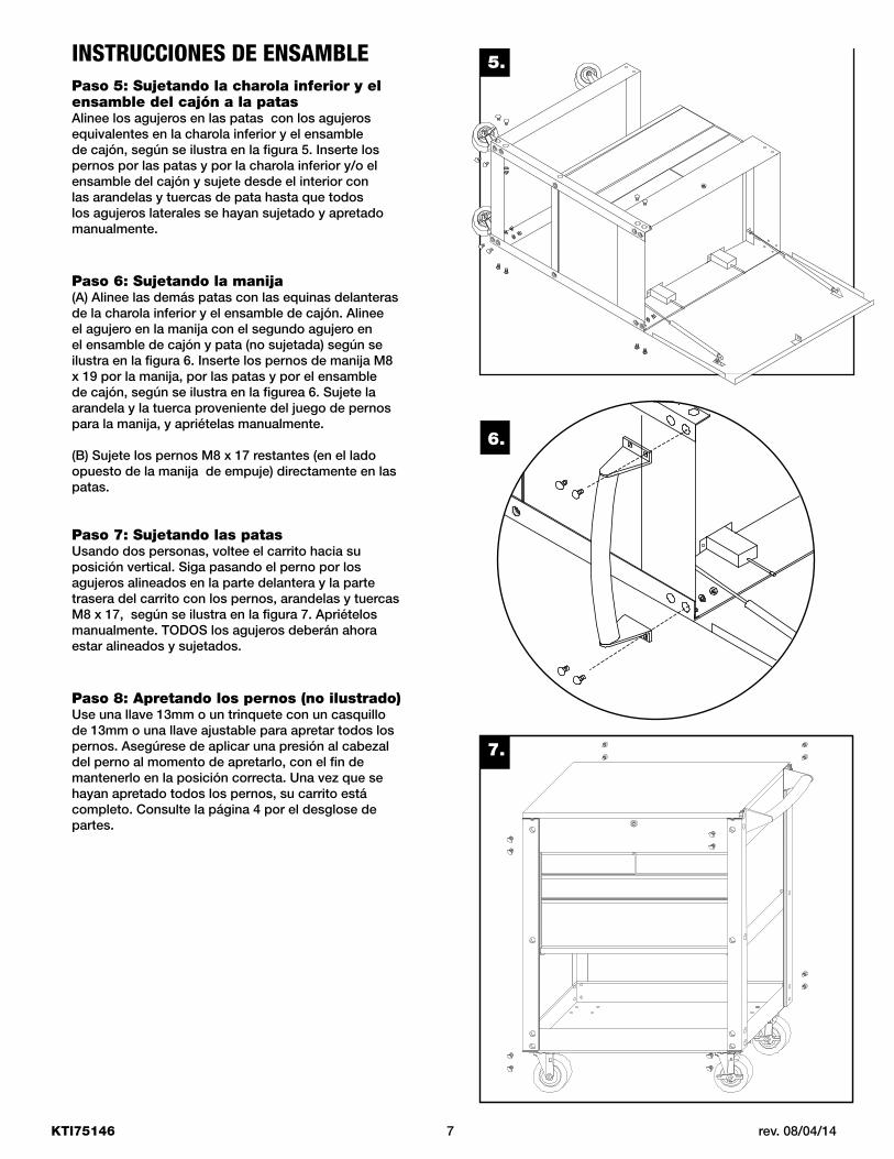
INSTRUCCIONES DE ENSAMBLE 5.
6.
7.
Paso 5: Sujetando la charola inferior y el ensamble del cajón a la patas Alinee los agujeros en las patas con los agujeros equivalentes en la charola inferior y el ensamble de cajón, según se ilustra en la figura 5. Inserte los pernos por las patas y por la charola inferior y/o el ensamble del cajón y sujete desde el interior con las arandelas y tuercas de pata hasta que todos los agujeros laterales se hayan sujetado y apretado manualmente.
Paso 6: Sujetando la manija(A) Alinee las demás patas con las equinas delanteras de la charola inferior y el ensamble de cajón. Alinee el agujero en la manija con el segundo agujero en el ensamble de cajón y pata (no sujetada) según se ilustra en la figura 6. Inserte los pernos de manija M8 x 19 por la manija, por las patas y por el ensamble de cajón, según se ilustra en la figurea 6. Sujete la arandela y la tuerca proveniente del juego de pernos para la manija, y apriételas manualmente.
(B) Sujete los pernos M8 x 17 restantes (en el lado opuesto de la manija de empuje) directamente en las patas.
Paso 7: Sujetando las patas Usando dos personas, voltee el carrito hacia su posición vertical. Siga pasando el perno por los agujeros alineados en la parte delantera y la parte trasera del carrito con los pernos, arandelas y tuercas M8 x 17, según se ilustra en la figura 7. Apriételos manualmente. TODOS los agujeros deberán ahora estar alineados y sujetados.
Paso 8: Apretando los pernos (no ilustrado)Use una llave 13mm o un trinquete con un casquillo de 13mm o una llave ajustable para apretar todos los pernos. Asegúrese de aplicar una presión al cabezal del perno al momento de apretarlo, con el fin de mantenerlo en la posición correcta. Una vez que se hayan apretado todos los pernos, su carrito está completo. Consulte la página 4 por el desglose de partes.

KTI75146 8 rev. 08/04/14
Lea y comprenda todas las instrucciones en el manual del usuario. • Máxima capacidad de carga (500 libras) No cargue el cajón más allá de su capacidad nominal (100 libras). • No cargue el estante más allá de su capacidad nominal (100 libras). • Las unidades pueden volcarse y pegarle a usted, así ocasionando lesiones personales. • No abra más de un cajón cargado a la vez. • No pise sobre ni adentro de los cajones. • Asegure la tapa y los cajones antes de moverlos. • No pise sobre ni adentro de los cajones. • Aplique el freno en las rodajas de seguridad durante cualquier momento que el carrito esté en su lugar. • Mueva el carrito lentamente cuando éste esté cargado, evite las grietas, agujeros y otras irregularidades del piso. • No jalar; empujar para dezplazar. • El deplazami to o carga inadecuados puede ocasionar lesiones. • Este producto puede contener sustancias químicas consideradas por el Estado de California como causantes de cáncer, de malformaciones congénitas u otros daños en el sistema reproductivo. Lávese bien las manos después de manipular el producto. • No cumplir con estas indicaciones puede provocar lesiones graves o peligro de muerte, así como daños materiales.
ADVERTENCIA
carrito de Servicio con parte Superior y cajoneS de Seguridad
y incLuye SujetadoreS de Barra de paLanca
KTI75146