kt400-c contents - pc...
TRANSCRIPT

4
KT400-C
Contents
Chapter 1 Specification ............................................. 81-1 KT400-C Mainboard Layout**..............................................9
1-2 Mainboard Specifications .................................................... 101-2.1 CPU Socket ................................................................................... 10
1-2.2 System Chipsets ........................................................................... 10
1-2.3 Memory ......................................................................................... 10
1-2.4 BIOS ............................................................................................... 10
1-2.5 Accelerated Graphics Port (AGP) Interface ........................... 10
1-2.6 Advanced System Power Management .................................... 11
1-2.7 Multi-I/O Functions .................................................................... 11
1-2.8 Expansion Slots ............................................................................ 11
1-2.9 AC’97 Audio Codec on board .................................................... 12
1-2.10 Hardware Monitor on board ................................................... 12
1-2.11 Form Factor ................................................................................ 12
1-3 Mainboard Specification Table ........................................... 13
1-4 Chipset System Block Diagram ........................................... 14
Chapter 2 Hardware Setup ..................................... 162-1 CPU Identification and Installation ................................... 17
2-1.1 CPU Identification Legends ....................................................... 17
2-1.2 CPU Installation with Socket 462 ............................................. 18
2-2 Memory Installation ............................................................. 192-2.1 To Install DDR SDRAM Module .............................................. 19
2-2.2 To Remove a DIMM .................................................................... 20
2-3 AGP Slot Installation ............................................................ 21
2-4 IDE Connector Installation ................................................. 22
2-5 Floppy Drive Connector ( FDC ) Installation ................... 23
2-6 ATX Power Supply Installation .......................................... 24

5
Contents
2-7 Jumper / Switch Settings ...................................................... 252-7.1 How to tackle the Jumpers: ....................................................... 26
2-7.2 SW1: CPU Clock/Overclock Select .......................................... 26
2-7.3 JBAT1: Clear CMOS .................................................................. 27
2-7.4 Jp1: Anti-burn Shield (ABSII) .................................................. 28
2-7.5 JP2: KB/Mouse Power On / Wake Up ..................................... 29
2-8 Other Connectors Configuration ........................................ 302-8.1 On-board FAN Connectors ........................................................ 30
2-8.2 USB Ports and USB Pin-headers .............................................. 31
2-8.3 Chassis Panel Connectors .......................................................... 32
2-8.4 PS/2 Mouse and PS/2 Keyboard ............................................... 32
2-8.5 CD-ROM Audio Connectors (CD-In1) .................................... 33
2-8.6 Thermal Connectors .................................................................... 34
2-8.7 Complex Pin-header (Front Panel Connectors) ..................... 35
2-8.8 JAUD1: Front Panel Audio Connector (optional) ................. 37
Chapter 3 Software Setup ....................................... 383-1 Open Up Support CD: .......................................................... 39
3-2 Proceed to VIA 4-IN-1 Drivers Installation ...................... 40
3-3 Proceed to AC’97 Audio Driver Installation ..................... 42
3-4 Install USB 2.0 Driver for Win98 / Me / 2000 / XP.......... 43
3-5 To Install Hardware Monitor Utility .................................. 453-5.1 Installation ................................................................................... 45
3-5.2 Verification .................................................................................. 46
Chapter 4 AMI BIOS Setup .................................... 484-1 About BIOS Setup ................................................................. 49
4-2 To Run BIOS Setup ............................................................... 49
4-3 About CMOS .......................................................................... 49
4-4 The POST ( Power On Self Test ) ....................................... 49

6
KT400-C
4-5 To Update BIOS ..................................................................... 50
4-6 BIOS SETUP --- CMOS Setup Utility ................................ 524-6.1 CMOS Setup Utility .................................................................... 52
4-6.2 Standard CMOS Setup ............................................................... 53
4-6.3 Advanced BIOS Features ........................................................... 56
4-6.4 Advanced Chipset Features ....................................................... 59
4-6.5 Power Management Features .................................................... 62
4-6.6 PNP / PCI Configurations .......................................................... 65
4-6.7 Integrated Peripherals ................................................................ 67
4-6.8 SmartDoc Anti-Burn Shield ....................................................... 70
4-6.9 Frequency/Voltage Control ....................................................... 72
4-6.10 System Information ................................................................... 74
4-6.11 Set Supervisor Password .......................................................... 75
4-6.12 Load Optimized Defaults ........................................................ 77
4-6.13 Save & Exit Setup ...................................................................... 77
4-6.14 Exit Without Saving .................................................................. 77
APPENDICES.......................................................... 78Appendix-1 Identify Mainboard Model Number ................... 79
Appendix-2 Technical Terms ...................................................... 80

7
Contents
ITEM CHECKUP
• Mainboard
• Mainboard User Manual
• Multi-lingual Quick Installation Guide
• Support CD
• Bundled Bonus Pack CD
• Bundled Bonus Pack Manual
• Cables :
ATA66/100/133 IDE Cable
FDD Cable
USB Cable (Optional)

8
KT400-C
Topics included in this chapter are:1-1 Mainboard Layout1-2 Mainboard Specifications**1-3 Mainboard Specification Table1-4 Chipset System Block Diagram
Introduction
Chapter 1 Specification
This mainboard features an integration of the powerful AMD proces-sors Athlon/Athlon XP/Duron and the North Bridge VIA Apollo KT400plus South Bridge VT8235, with which the whole system performancesupports 333/266/200 MHz system bus.
VIA Apollo KT400 plus VT8235 supports on-board AMD processorsto implement the 333/266/200MHz Front Side Bus, the AGP 8X/4Xinterface, the LPC Super I/O, the DDR *400/333 MHz SDRAM, the 2-channel AC’97 Audio interface, the USB 2.0 interface and ATA 133/100/66 data transfer rate. This chapter is to introduce to users every ad-vanced function of this high performance integration.
** If any difference is found between this manual and the Main-board you are using, please look up the ERRATA/UPDATE Slipenclosed inside for the correction or updated information, orelse contact the Mainboard Dealer or visit our Web Site for thelatest manual update.

9
Chapter 1 Specification
1-1 KT400-C Mainboard Layout**
PCI 1
PCI 2
PCI 3
PCI 4
PCI 5
VIAKT400
IDE1
IDE2
LiBattery
Fan3
VIA
VT8235
FDC1
CO
M1
CO
M2
LP
T1
MIC
Lin
e�
Ou
tL
ine�
In
Gam
e/M
IDI
Port
AGP 8X/4X
ClockGenerator
JBAT1Speaker RST PLED
HDD/LED IR PWR+ +- -
+ -
USB3
1
CN
8
DIM
M1
DD
R 4
00
/33
3/2
66
MH
z
�
USB1
PS/2 K/B
Mouse(on top)
(underside)
Fan
1
1 JP2
1
JP1
Socket 462
USB2
1 9 9
�
�
LPC I/OIT8705
RT2
�
1
CD-In1
�
AC'97Codec
JAUD1
BIOS
1 9
1
ALC202A
Fan2
SW1
ON DIP
1 2 3 4 5�
DIM
M2
(underside)
(on top)USB0
RT1
1
1
1
(DD
R 4
00
MH
z C
ON
DIT
ION
AL
LY
SU
PP
OR
TE
D)

10
KT400-C
1-2 Mainboard Specifications
1-2.1 CPU SocketCPU Socket 462 (Socket A) on board, supporting AMD Athlon, AthlonXP and Duron processors and implementing 333/266/200MHz systembus
1-2.2 System Chipsets• North Bridge VIA KT400 for managing and supporting 333/266/
200MHz system Bus, AGP 8X/4X interface and DDR 333/266MHzMemory Interface *with an enhanced support of DDR 400MHzMemory Module which should have passed Soltek DDR 400 MemoryModule Validation.
• South Bridge VIA VT8235 working with North Bridge KT400 supportingthe V-Link, LPC Super I/O, PCI interface, ATA133 interface, USB V2.0 interface, as well as AC’97 Audio 2-channel interface.
1-2.3 Memory2 DDR DIMM 184-pin slots on board :• Supporting unregistered, non-ECC *DDR 400/333/266/200 SDRAM
up to 2 GBs (DDR 400 Module supported conditionally)• Supporting installation of mixed volumes yet same type of DDR
SDRAM modules* Soltek Computer Inc. typically runs a DDR 400 Memory Module
Validation Program for Chipset VIA KT400/P4X400A. Detailedinformation is available in Soltek Web Site: www.soltek.com.tw
1-2.4 BIOS• Supporting Plug & Play V1.0• Flash Memory for easy upgrade• Supporting BIOS Writing Protection and Year 2000 compliant• Supporting BIOS Setup (See Chapter 4 BIOS Setup)
1-2.5 Accelerated Graphics Port (AGP) InterfaceAGP Controller embedded on board, supporting: • 1.5V(8X/4X) power mode only, 1 AGP Slot supported • 8X 66MHz AD and SBA signaling; AGP pipelined split-transaction
longburst transfers up to 2GB/sec. • AGP 8X/4X supported, AGP V3.0 compliant

11
Chapter 1 Specification
1-2.7 Multi-I/O Functions• PCI EIDE Controller, supporting:
-- 2 ATA 133 / 100 / 66 IDE connectors supporting up to 4 IDE devices
• Dedicated IR Functions: -- 1x5 IR connector dedicated to IR function with Infrared-IrDA (HPSIR)
and ASK (Amplitude Shift Keyed) IR
• Multi-mode parallel data transfer: -- Standard mode, high speed mode ECP and enhanced mode EPP
• Floppy Drive Connector: -- 1 FDD connector supporting 2 floppy drives with drive swap support
• Universal Serial Bus Transfer Mode: -- USB V2.0 compliant, 480 Mb/s USB Bus, supporting Win 98 and later
operating systems; USB drivers provided in Support CD for installation
-- 2 built-in USB connectors and 2 more USB pin-headers which require 2
optional USB cables to provide 4 more USB ports
• PS/2 Keyboard and PS/2 Mouse• UARTs (Universal Asynchronous Receiver / Transmitter):
-- 2 complete serial ports (COM1 & COM2) on board
1-2.8 Expansion Slots• 5 PCI Bus Master slots• 1 AGP 8X/4X slot• 2 DDR DIMM slots
1-2.6 Advanced System Power ManagementAdvanced Configuration and Power Interface incorporated in BIOS forreducing power consumption :• ACPI 1.0 compliant (Advanced Configuration and Power Interface)• APM V1.2 compliant (Legacy Power Management)• ACPI Suspend function supported• PS/2 Keyboard & Mouse Power On• Real Time Clock (RTC) with date alarm, month alarm, and century
field

12
KT400-C
1-2.9 AC’97 Audio Codec on boardAC’97 Audio Codec on board, 2-channel interface compliant
1-2.10 Hardware Monitor on board• Hardware Monitor integrated in LPC I/O IT8705F, providing monitor-
ing functions on hardware voltage, temperatures and fan speeds.• Utility Software SmartGuardian for displaying monitor status is en-
closed in Support CD for user’s installation.
1-2.11 Form Factor• ATX form factor, ATX power supply• Mainboard size: 305mm x 190mm

13
Chapter 1 Specification
1-3 Mainboard Specification Table
CPU
North Bridge
South Bridge
BIOS
Memory
I/O Chip
AGP interface
Audio
IDE Interface
VGA
PCI Slots
I/O Connectors
Other commonfeatures
Socket 462 for AMD Athlon, Athlon XP, Duron CPU
VIA KT400, supporting 333/266/200 MHz FSB
VT8235
AMI BIOS
Supporting DDR *400/333/266 SDRAM, up to 2GBin 2 DDR SDIMM slots
ITE IT8705F with Hardware Monitor
AGP 8X/4X mode only
AC’97 Audio Codec, 2-channel compliant
2 ATA 133/100/66 IDE
Not integrated on board
5 PCI Master slots on board
6 USB V2.0, 1 FDD port, 2 COM ports, 1 LPT,1 IrDA, 1 PS/2 K/B, 1 PS/2 Mouse
BIOS Writing Protection;Keyboard/ Mouse Power On;ATX Power Supply;ATX form factor
KT400-C Specifications and Features

14
KT400-C
1-4 Chipset System Block Diagram
Socket 462 + VIA KT400 + VIA VT8235 Diagram
Socket 462
System Bus 333/266/200MHz
for AMD CPUs
SystemMemory
DDR memoryInterface
DDR 400/333/266SDRAM
AGP SlotAGP 8X/4X
V-Link
PCI Bus
AC’97
ATA 133/100/664 IDEDevices
USB Bus V2.0
USBPorts
5 PCI Slots
Audio Codec(2-channel)
IR
FDD
Serial Ports
Printer Port
Game/MIDI
H/Monitor
BIOSLPC I/OIT8705
VIA KT400North Bridge
VT8235 South BridgeMouse
Keyboard

16
KT400-C
Chapter 2 Hardware Setup
1. We recommend to install your CPU before any other components.For detailed installation instructions of processor, you can also referto the pamphlet enclosed in your CPU package.
2. Installing a cooling fan with a good heatsink is a must for proper heatdissipation for your CPU. Get ready an appropriate fan with heatsinkfor proper installation. Improper fan and installation will damage yourCPU.
3. In case CPU Vcore, CPU clock or Frequency Ratio is adjustable onboard, please follow the instructions described in the User Manualfor proper setup. Incorrect setting will cause damage to your CPU.
The following topics are included in this chapter:
To Get Things Ready for Hardware Setup !
2-1 CPU Identification and Installation2-2 Memory Installation2-3 AGP Slot Installation2-4 IDE Connector Installation2-5 Floppy Drive Connector ( FDC ) Installation2-6 ATX Power Supply Installation2-7 Jumper Settings2-8 Other Connectors Configuration2-9 IRQ Description

17
Chapter 2 Hardware Setup
2-1 CPU Identification and Installation
2-1.1 CPU Identification Legends
AMD
AM
D A
thlonT
MA
XD
A2400D
KV
3CR
FB
CY
A5280061
XX
XX
XX
XX
XX
XX
XX
XX
XX
XX
XX
X
Family / Architecture: A, AX, AXDA=AMD Athlon Processor D, DHD=AMD Duron Processor
Speed: 1000=1000MHz, 1600=1400MHz, 1700=1467MHz,1800=1533Mhz, 1900=1600MHz, 2000=1667MHz, 2100=1733MHz,2200=1800MHz, 2400=2000MHz, 2700=2167MHz
Package Type: M=Card Module, A=PGA, D=OPGA
Voltage: L=1.5V, U=1.6V, K=1.65V, P=1.7V, M=1.75V, N=1.8V
Case Temperature: Q=60˚C, X=65˚C, R=70˚C, Y=75˚C, T=90˚C, S=95˚C
Size of L2 Cache: 1=64Kbyte, 2=128Kbyte, 3=256Kbyte
Max FSB: A=B=200MHz, C=266MHz, D=333MHzNote: Get the Host CPU Clock by dividing FSB by 2.
(1)
(2)
(3)
(4)
(5)
(6)
(7)
AMD Athlon(Duron)AX 1900 D M T 3 C(1) (2) (3) (4) (5) (6) (7)
AMD
XXXXXXXXXXXXXXXXXXXXXXXXXXXXXXXXXXXXXXXXXXXXXXXXXXXXXX
.18 micron process CPU .13 micron process CPU

18
KT400-C
AMD
SOCKET 462
SOCKET 462
2-1.2 CPU Installation with Socket 462
This mainboard is built with CPU Socket 462 supporting the AMD CPUsAthlon, Athlon XP and Duron:• Follow the steps described in this section to install CPU into the on-
board Socket 462.• After installation of CPU, you must also install a proper cooling fan
on top of the CPU and connect the Fan cable to the CPU fanconnector.
1. First pull sideways the lever ofSocket 462, and then turn it up900 so as to raise the upper layerof the socket from the lowerplatform.
3. Make sure that all CPU pins havecompletely entered the socketand then lower down the leverto lock up CPU to socket.
2. Configure Pin 1 of CPU to Pin 1of the Socket, just as the wayshown in the diagram on theright. Adjust the position of CPUuntil you can feel all CPU pinsget into the pin holes of thesocket.
Pin 1
Pin 1
SOCKET 462
AMD

19
Chapter 2 Hardware Setup
2-2 Memory InstallationHow to tackle the memory Modules:• Make sure to unplug your power supply before adding or removing
memory module. Failure to do so may cause severe damage to bothyour mainboard and the memory module.
• Pay attention to the orientation of the DIMM slots. Forcing a DIMMinto a slot improperly will damage the memory module and slot itself.
• Make sure you have the right type of memory module for yourmainboard.
184-Pin DIMM Notch Key Definitions
DRAM Key Position Voltage Key Position
Module Latch
• This series supports up to 2GB unbuffered *DDR 400/333/266 SDRAM,with 2 DDR DIMM slots on board. Do not insert other type of mod-ules into these slots. Memory support is upgradable to DDR 400 with-out guarantee of success in BIOS Setup.
* DDR 400 Module is supported on condition that the module haspassed Soltek DDR 400 Memory Module Validation Test. SoltekComputer Inc. typically runs a DDR 400 Memory Module ValidationProgram for Chipset VIA KT400/P4X400A. Detailed information isavailable in Soltek Web Site: www.soltek.com.tw
• DDR DIMM slot has 184-pins and one notch. Insert a DDR SDRAMvertically into the 184-pin slot with the notch-to-rib matching.
2-2.1 To Install DDR SDRAM Module
DDR Notch
DDR Rib
2.5V

20
KT400-C
PCI 1
PCI 2
PCI 3
PCI 4
PCI 5
VIAKT400
IDE1
IDE2
LiBattery
Fan3
VIA
VT8235
FDC1
CO
M1
CO
M2
LP
T1
MIC
Lin
e�
Ou
tL
ine�
In
Gam
e/M
IDI
Port
AGP 8X/4X
ClockGenerator
JBAT1Speaker RST PLED
HDD/LED IR PWR+ +- -
+ -
USB3
1
CN
8
DIM
M1
DD
R 4
00/3
33/2
66 M
Hz
�
USB1
PS/2 K/B
Mouse(on top)
(underside)
Fan
1
1 JP2
1
JP1
Socket 462
USB2
1 9 9
�
�
LPC I/OIT8705
RT2
�
1
CD-In1
�
AC'97Codec
JAUD1
BIOS
1 9
1
ALC202A
Fan2
SW1
ON DIP
1 2 3 4 5�
DIM
M2
(underside)
(on top)USB0
RT1
1
1
1
(DD
R 4
00
MH
z C
ON
DIT
ION
AL
LY
SU
PP
OR
TE
D)
D D R D I M M S l o t s(184-pin)
2-2.2 To Remove a DIMMPress down the holding latches on both sides of slot to release themodule from the DIMM slot.

21
Chapter 2 Hardware Setup
PCI 1
PCI 2
PCI 3
PCI 4
PCI 5
VIAKT400
IDE1
IDE2
LiBattery
Fan3
VIA
VT8235
FDC1
CO
M1
CO
M2
LP
T1
MIC
Lin
e�
Ou
tL
ine�
In
Gam
e/M
IDI
Port
AGP 8X/4X
ClockGenerator
JBAT1Speaker RST PLED
HDD/LED IR PWR+ +- -
+ -
USB3
1
CN
8
DIM
M1
DD
R 4
00/3
33/2
66 M
Hz
�
USB1
PS/2 K/B
Mouse(on top)
(underside)
Fan
1
1 JP2
1
JP1
Socket 462
USB2
1 9 9
�
�
LPC I/OIT8705
RT2
�
1
CD-In1
�
AC'97Codec
JAUD1
BIOS
1 9
1
ALC202A
Fan2
SW1
ON DIP
1 2 3 4 5�
DIM
M2
(underside)
(on top)USB0
RT1
1
1
1
(DD
R 4
00
MH
z C
ON
DIT
ION
AL
LY
SU
PP
OR
TE
D)
2-3 AGP Slot Installation
The AGP slot on board supports 1.5V AGP 8X/4X card only. A Rib isspecifically added to the 8X/4X slot so as to match the AGP 8X/4X card.To insert a 3.3V AGP 2X card into the AGP 4X slot will damage thesystem chip and burn the 1.5V circuitry.An AGP 8X card will support a data transfer rate up to 2GB/sec., whilean AGP 4X card will provide 1GB/sec transfer rate.
AGP Accelerator
notch
AGP 8X/4X Slot

22
KT400-C
PCI 1
PCI 2
PCI 3
PCI 4
PCI 5
VIAKT400
IDE1
IDE2
LiBattery
Fan3
VIA
VT8235
FDC1
CO
M1
CO
M2
LP
T1
MIC
Lin
e�
Ou
tL
ine�
In
Gam
e/M
IDI
Port
AGP 8X/4X
ClockGenerator
JBAT1Speaker RST PLED
HDD/LED IR PWR+ +- -
+ -
USB3
1
CN
8
DIM
M1
DD
R 4
00/3
33/2
66 M
Hz
�
USB1
PS/2 K/B
Mouse(on top)
(underside)
Fan
1
1 JP2
1
JP1
Socket 462
USB2
1 9 9
�
�
LPC I/OIT8705
RT2
�
1
CD-In1
�
AC'97Codec
JAUD1
BIOS
1 9
1
ALC202A
Fan2
SW1
ON DIP
1 2 3 4 5�
DIM
M2
(underside)
(on top)USB0
RT1
1
1
1
(DD
R 4
00
MH
z C
ON
DIT
ION
AL
LY
SU
PP
OR
TE
D)
2-4 IDE Connector Installation
Gray Connector
Blue Connector
Black Connector
Red Line
IDE Flat Cable(To Mainboard)
(To Slave Device)
(To Master Device)
To install IDE Connector, you may connect the blue connector of IDEcable to the primary (IDE1) or secondary (IDE2) connector on board,and then connect the gray connector to your slave device and the blackconnector to your master device. If you install two hard disks, you mustconfigure the second drive to slave mode by setting its jumpers correctly.Please refer to your hard disk documentation for the jumper settings.
ATA IDE connectors:Orient the red line on the IDEFlat Cable to Pin1.
Pin 1 (to Red Line)
IDE2
IDE1

23
Chapter 2 Hardware Setup
PCI 1
PCI 2
PCI 3
PCI 4
PCI 5
VIAKT400
IDE1
IDE2
LiBattery
Fan3
VIA
VT8235
FDC1
CO
M1
CO
M2
LP
T1
MIC
Lin
e�
Ou
tL
ine�
In
Gam
e/M
IDI
Port
AGP 8X/4X
ClockGenerator
JBAT1Speaker RST PLED
HDD/LED IR PWR+ +- -
+ -
USB3
1
CN
8
DIM
M1
DD
R 4
00
/33
3/2
66
MH
z
�
USB1
PS/2 K/B
Mouse(on top)
(underside)
Fan
1
1 JP2
1
JP1
Socket 462
USB2
1 9 9
�
�
LPC I/OIT8705
RT2
�
1
CD-In1
�
AC'97Codec
JAUD1
BIOS
1 9
1
ALC202A
Fan2
SW1
ON DIP
1 2 3 4 5�
DIM
M2
(underside)
(on top)USB0
RT1
1
1
1
(DD
R 4
00
MH
z C
ON
DIT
ION
AL
LY
SU
PP
OR
TE
D)
To install FDC, you should connect the end of FDC cable with singleconnector to the board, and connect the other end with two connectorsto the floppy drives.
2-5 Floppy Drive Connector ( FDC ) Installation
To 1st Floppy DriveTo mainboard
To 2nd Floppy Drive
Red line
Floppy Drive Connector:
Orient the red line of theFloppy Flat Cable to Pin1.
Pin 1 (to Red Line)
FDD Cable

24
KT400-C
PCI 1
PCI 2
PCI 3
PCI 4
PCI 5
VIAKT400
IDE1
IDE2
LiBattery
Fan3
VIA
VT8235
FDC1
CO
M1
CO
M2
LP
T1
MIC
Lin
e�
Ou
tL
ine�
In
Gam
e/M
IDI
Port
AGP 8X/4X
ClockGenerator
JBAT1Speaker RST PLED
HDD/LED IR PWR+ +- -
+ -
USB3
1
CN
8
DIM
M1
DD
R 4
00
/33
3/2
66
MH
z
�
USB1
PS/2 K/B
Mouse(on top)
(underside)
Fan
1
1 JP2
1
JP1
Socket 462
USB2
1 9 9
�
�
LPC I/OIT8705
RT2
�
1
CD-In1
�
AC'97Codec
JAUD1
BIOS
1 9
1
ALC202A
Fan2
SW1
ON DIP
1 2 3 4 5�
DIM
M2
(underside)
(on top)USB0
RT1
1
1
1
(DD
R 4
00
MH
z C
ON
DIT
ION
AL
LY
SU
PP
OR
TE
D)
2-6 ATX Power Supply Installation
To set up Power Supply on this series:1. Connect the on-board Main Power Connector (20-pin) to the Main
Power Connector (20-pin) of an ATX Power Supply which can beeither of the latest version 2.03 or of earlier ATX model.
Main Power Connector(20-pin)
+12V5SB
PWR OK
GND
GND
GND
GND
GND
+5V+5V
-5V
+5V
+5V
+3.3V+3.3V
-12V
PS ON#
Pin1 Pin11
GNDGND
+3.3V

25
Chapter 2 Hardware Setup
PCI 1
PCI 2
PCI 3
PCI 4
PCI 5
VIAKT400
IDE1
IDE2
LiBattery
Fan3
VIA
VT8235
FDC1
CO
M1
CO
M2
LP
T1
MIC
Lin
e�
Ou
tL
ine�
In
Gam
e/M
IDI
Port
AGP 8X/4X
ClockGenerator
JBAT1Speaker RST PLED
HDD/LED IR PWR+ +- -
+ -
USB3
1
CN
8
DIM
M1
DD
R 4
00
/33
3/2
66
MH
z
�
USB1
PS/2 K/B
Mouse(on top)
(underside)
Fan
1
1 JP2
1
JP1
Socket 462
USB2
1 9 9
�
�
LPC I/OIT8705
RT2
�
1
CD-In1
�
AC'97Codec
JAUD1
BIOS
1 9
1
ALC202A
Fan2
SW1
ON DIP
1 2 3 4 5�
DIM
M2
(underside)
(on top)USB0
RT1
1
1
1
(DD
R 4
00
MH
z C
ON
DIT
ION
AL
LY
SU
PP
OR
TE
D)
2-7 Jumper / Switch SettingsThe following diagrams show the locations and settings of jumper / switchblocks on the mainboard.
JBAT1
1-2 closed (default)To hold data
1
1
2-3 closedTo clear CMOS
Clear CMOS
1
1
JP1:
1-2 closed (default)
2-3 closed
(Overheated CPU Shutdown)
(only for Athlon XP/Duron Morgan)
Enable overheated CPU (85oC) shutdown function
Disable overheated CPU shutdown function
Anti-burn Shield (ABSII)
CPU Clock SW1-1 SW1-2 SW1-3 SW1-4 SW1-5
1 2 3 4 5
100MHz Off On Off Off Off
133MHz On Off On Off Off
166MHz On Off On On On
SW1 (5-Dip): CPU Clock/Overclock Select
SW1 (5-Dip)
(default)
On
Off
Keyboard/MousePower On / Wake Up
JP2:
1-2 closed
2-3 closed
KB/Mouse Power On /Wake Up Enabled1
1KB/Mouse Power On / WakeUp Disabled
(default)

26
KT400-C
SW1 is designed on board as a 5-dip switch for CPU clock select.
2-7.2 SW1: CPU Clock/Overclock Select
2. Select the CPU clock you want from 100/133/166MHz and set SW1to match your choice.
3. If you select a CPU clock which is higher than your default CPUclock, it means that an overclock is desired. However, if an overclokfails to boot system, you should restore the default setting and thenclear CMOS to rebooting your system. (See Clear CMOS in nextparagraph.)
1. Before setting the CPU clock, read the Identification Legend on theCPU, find the Max FSB and divide it by two. The result is the defaultCPU clock.
1 13 31 3
Jumper withPin 2-3 closed
Jumper withall pins open
Jumper withPin 1-2 closed
If a pin-header (of 2 or more pins) isdesigned in such a way that its pinscan be closed or linked together toset up a specific function, this headeris called a jumper in this manual.
A 3-pin Jumper
The conductor inside the caplinks two header-pins together.
• A Jumper is usually but not necessarily given a “JpX” legend.
Jp X
• Do not remove any jumper cap when power is on. Alwaysmake sure the power is off before changing any jumper settings.Otherwise, mainboard could be damaged.
2-7.1 How to tackle the Jumpers:
• In the Jumper setting diagram, all jumper pins covered withblack marks stand for closed pins with jumper cap.
1 2 3 A 2-pinJumperCap
CPU Clock SW1-1 SW1-2 SW1-3 SW1-4 SW1-5
1 2 3 4 5
100MHz Off On Off Off Off
133MHz On Off On Off Off
166MHz On Off On On On
SW1 (5-Dip): CPU Clock/Overclock Select
SW1 (5-Dip)
(default)
On
Off

27
Chapter 2 Hardware Setup
When you have problem with rebooting your system, you can clearCMOS data and restore it to default value. To clear CMOS with JumperJBAT1, please follow the steps below:1. Power off system.2. Set JBAT1 to Pin 2-3 closed.3. After 2 or 3 seconds, return the JBAT1 setting to Pin1-2 closed.4. CMOS data are restored to default. Remember never clear CMOS
when system power is on.
2-7.3 JBAT1: Clear CMOS
JBAT1
1-2 closed (default)To hold data
1
1
2-3 closedTo clear CMOS
Clear CMOS
Further notes on CPU Overclocking:1. If you have successfully booted system with or without CPU overclock,
you still can do another CPU overclock in BIOS Setup. Please enterBIOS Setup, choose “Frequency/Voltage Control” menu, and takethe “Use Linear” option of the “Use CPU Linear Frequency”. Thenconfigure the “CPU Clock” item to raise your CPU clock.
2. CPU overclocking should take all components on board into account.If you fail in BIOS overclocking, you will not be able to restart system.In such case, power off system and clear CMOS by JBAT1 as statedbelow and then restart your system. And remember to reconfigurewhatever should be reconfigured.
3. If your system is already fixed in a cabinet or case, you may not liketo take the trouble to clear CMOS. Then power on your system withthe power button on the case and simultaneously press down the“Insert” key of the keyboard until you see the initial bootup screenappear. And remember you should also enter CMOS BIOS Setupand choose “Load Optimized Defaults” to restore default BIOS .

28
KT400-C
2-7.4 Jp1: Anti-burn Shield (ABSII)
JP1 is designed to enable the overheat safeguard for some CPUs whichare incorporated with a protective thermal diode. The latest AMD AthlonXP and Duron Morgan CPUs are incorporated with such thermal diodeand can be protected by this function. Setting JP1 1-2 closed (defaultsetting) will get system shutdown when any of the above-mentionedCPUs gets to 85oC (the default protection temperature.) Only when theCPU returns to a cooler state can you restart your system.For other CPUs that are not incorporated with a protective thermal diode,please set JP1 2-3 closed to disable the function because it is a vaindesign now.
Reminder: If a sudden shutdown happens to your system which hasbeen running well for a while with an AMD Athlon XP/Duron MorganCPU, this might be caused by the “Overheated CPU Shutdown” design.Please use a better CPU cooling fan to restart your system.
1
1
JP1:
1-2 closed (default)
2-3 closed
(Overheated CPU Shutdown) (only for Athlon XP/ Duron Morgan)
Enable overheated CPU (85oC) shutdown function
Disable overheated CPUshutdown function
Anti-burn Shield (ABSII)

29
Chapter 2 Hardware Setup
2-7.5 JP2: KB/Mouse Power On / Wake Up
JP2 is designed on board as a jumper to enable/disable the PS/2 key-board/mouse Power On/Wake Up from system off or suspend mode.Yet users should still enter BIOS setup to choose the Wake Up/ PowerOn mode.USB keyboard/mouse Wake Up function is not supported in thismainboard.
Keyboard/MousePower On / Wake Up
JP2:
1-2 closed
2-3 closed
KB/Mouse Power On /Wake Up Enabled1
1KB/Mouse Power On / WakeUp Disabled
(default)

30
KT400-C
PCI 1
PCI 2
PCI 3
PCI 4
PCI 5
VIAKT400
IDE1
IDE2
LiBattery
Fan3
VIA
VT8235
FDC1
CO
M1
CO
M2
LP
T1
MIC
Lin
e�
Ou
tL
ine�
In
Gam
e/M
IDI
Port
AGP 8X/4X
ClockGenerator
JBAT1Speaker RST PLED
HDD/LED IR PWR+ +- -
+ -
USB3
1
CN
8
DIM
M1
DD
R 4
00
/33
3/2
66
MH
z
�
USB1
PS/2 K/B
Mouse(on top)
(underside)
Fan
1
1 JP2
1
JP1
Socket 462
USB2
1 9 9
�
�
LPC I/OIT8705
RT2
�
1
CD-In1
�
AC'97Codec
JAUD1
BIOS
1 9
1
ALC202A
Fan2
SW1
ON DIP
1 2 3 4 5�
DIM
M2
(underside)
(on top)USB0
RT1
1
1
1
(DD
R 4
00
MH
z C
ON
DIT
ION
AL
LY
SU
PP
OR
TE
D)
2-8 Other Connectors ConfigurationThis section lists out all connectors configurations for users’ reference.
Both Sensor and No-sensor Fan Connectors support CPU/AGP/Sys-tem/Case cooling fan with +12V mode. When connecting the wire toany Fan Connector, user should make sure that the red wire is for thepositive current and should be connected to pin +12V, and the blackwire is Ground and should be connected to pin GND. A Hardware Moni-tor chipset is on board, with which user can install a Hardware MonitorUtility and read the fan speed transmitted from the sensor fan connector.Otherwise, user can read the fan speed from the “Hardware MonitorStatus” in CMOS BIOS.
A running fan will send out 2 electric pulses per rotation of its fanblade to a Sensor Fan Connector which in turn will count the electricpulses and send the information to the System Hardware Monitor. Thehardware Monitor Program will work out the fan rotation speed and dis-play it on screen.
GND+12VSENSOR
Void+12V
GND
2-8.1 On-board FAN Connectors
Sensor Conn.No Sensor
FAN2, Sensor Fan Connector(Yellow)
FAN1, Sensor Fan Connector(Yellow)
FAN3, No-sensor Fan Connector

31
Chapter 2 Hardware Setup
PCI 1
PCI 2
PCI 3
PCI 4
PCI 5
VIAKT400
IDE1
IDE2
LiBattery
Fan3
VIA
VT8235
FDC1
CO
M1
CO
M2
LP
T1
MIC
Lin
e�
Ou
tL
ine�
In
Gam
e/M
IDI
Port
AGP 8X/4X
ClockGenerator
JBAT1Speaker RST PLED
HDD/LED IR PWR+ +- -
+ -
USB3
1
CN
8
DIM
M1
DD
R 4
00/3
33/2
66 M
Hz
�
USB1
PS/2 K/B
Mouse(on top)
(underside)
Fan
1
1 JP2
1
JP1
Socket 462
USB2
1 9 9
�
�
LPC I/OIT8705
RT2
�
1
CD-In1
�
AC'97Codec
JAUD1
BIOS
1 9
1
ALC202A
Fan2
SW1
ON DIP
1 2 3 4 5�
DIM
M2
(underside)
(on top)USB0
RT1
1
1
1
(DD
R 4
00
MH
z C
ON
DIT
ION
AL
LY
SU
PP
OR
TE
D)
2-8.2 USB Ports and USB Pin-headers
This series provides two USB ports USB0 and USB1 on board sup-porting various USB devices. In addition, two USB pin-headers areadded on board to provide expansion of four more optional USB portsby using two additional USB Cables. User can order the optional USBcables from your mainboard dealer or vender.
When plugging the USB cable to USB Header, user must make surethe red wire is connected to Pin 1.
All 6 USB ports are compliant with 1.0 / 2.0 USB Bus. USB 2.0 sup-ports Win 98 and above. USB 1.0 / 2.0 drivers are provided in SupportCD for user’s installation.
1
USB Cable (Optional)
Red wire
USB Port
1
10
10
USB connectors USB0 and USB1 (underside)
USB Pin-headers USB2 and USB3
USB Header
1
10
First USB Port Wiring for Front USB
Second USB Port Wiring for Front USB
+5V
Red White
black+5VRed
Green
GreenWhite
blackGND
GND
Pin Assignment
D1- D1+
D2- D2+

32
KT400-C
2-8.4 PS/2 Mouse and PS/2 Keyboard
A : PS/2 MouseB : Port USB 0C : LPT1 PORTD : Game/MIDIE : PS/2 KeyboardF : USB 1 (Underside)
G : COM 1H : COM 2I : Line OutJ : Line InK : Microphone Input
A.
E. F. G. H. I. J. K.
B. C. D.
(PS/2 Mouse: On top of keyboard connector, Green Color)
(PS/2 Keyboard Connector: Underside, Purple Color)
6
4
2 1
3
5Void
Vcc
Keyboard Clock
GND
Keyboard DataVoid
6
4
2 1
3
5Void
Vcc
Mouse Clock
GND
Mouse DataVoid
2-8.3 Chassis Panel Connectors

33
Chapter 2 Hardware Setup
PCI 1
PCI 2
PCI 3
PCI 4
PCI 5
VIAKT400
IDE1
IDE2
LiBattery
Fan3
VIA
VT8235
FDC1
CO
M1
CO
M2
LP
T1
MIC
Lin
e�
Ou
tL
ine�
In
Gam
e/M
IDI
Port
AGP 8X/4X
ClockGenerator
JBAT1Speaker RST PLED
HDD/LED IR PWR+ +- -
+ -
USB3
1
CN
8
DIM
M1
DD
R 4
00/3
33/2
66 M
Hz
�
USB1
PS/2 K/B
Mouse(on top)
(underside)
Fan
1
1 JP2
1
JP1
Socket 462
USB2
1 9 9
�
�
LPC I/OIT8705
RT2
�
1
CD-In1
�
AC'97Codec
JAUD1
BIOS
1 9
1
ALC202A
Fan2
SW1
ON DIP
1 2 3 4 5�
DIM
M2
(underside)
(on top)USB0
RT1
1
1
1
(DD
R 4
00
MH
z C
ON
DIT
ION
AL
LY
SU
PP
OR
TE
D)
2-8.5 CD-ROM Audio Connectors (CD-In1)
CD-In1 is an audio connector connecting CD-ROM audio to mainboard.
CD-ROM Audio Connector
1
CD-In1
Pin 1
Pin 2
Pin 3
Pin 4
Left Channel
GND
GND
Right Channel
Pin Signal

34
KT400-C
PCI 1
PCI 2
PCI 3
PCI 4
PCI 5
VIAKT400
IDE1
IDE2
LiBattery
Fan3
VIA
VT8235
FDC1
CO
M1
CO
M2
LPT
1M
ICL
ine�
Ou
tL
ine�
In
Gam
e/M
IDI
Port
AGP 8X/4X
ClockGenerator
JBAT1Speaker RST PLED
HDD/LED IR PWR+ +- -
+ -
USB3
1
CN
8
DIM
M1
DD
R 4
00/3
33/2
66 M
Hz
�
USB1
PS/2 K/B
Mouse(on top)
(underside)
Fan1
1 JP2
1
JP1
Socket 462
USB2
1 9 9
�
�
LPC I/OIT8705
RT2
�
1
CD-In1
�
AC'97Codec
JAUD1
BIOS
1 9
1
ALC202A
Fan2
SW1
ON DIP
1 2 3 4 5�
DIM
M2
(underside)
(on top)USB0
RT1
1
1
1
(DD
R 4
00M
Hz
CO
ND
ITIO
NA
LLY
SU
PPO
RT
ED
)
2. Connector RT2: A thermal cable is needed to connect RT2 to on-board devices such as HDD, Graphics card etc., so as to detect thetemperature generated therein. Please connect the end (a) of thethermal cable to RT2, and tape another end (b) of the thermal cableon to the device which you want to monitor. After you have finishedthe thermal cable installation, you will see the detected temperaturein BIOS setup or Hardware Monitor utility.
1. Connector RT1: A thermal resistor is mounted by default to connectorRT1 so as to detect the temperature of the CPU. What RT1 does isto transmit the thermal signal to BIOS or Hardware Monitor.
RT1 is mountedwith Thermal Resistorby default.
To Devices
To RT2
Thermal Cable
RT1
RT2
(Optional)
2-8.6 Thermal Connectors

35
Chapter 2 Hardware Setup
PCI 1
PCI 2
PCI 3
PCI 4
PCI 5
VIAKT400
IDE1
IDE2
LiBattery
Fan3
VIA
VT8235
FDC1
CO
M1
CO
M2
LPT1
MIC
Lin
e�O
utL
ine�
In
Gam
e/M
IDI
Por
t
AGP 8X/4X
ClockGenerator
JBAT1Speaker RST PLED
HDD/LED IR PWR+ +- -
+ -
USB3
1
CN
8
DIM
M1
DD
R 4
00/3
33/2
66 M
Hz
�
USB1
PS/2 K/B
Mouse(on top)
(underside)
Fan1
1 JP2
1
JP1
Socket 462
USB2
1 9 9
�
�
LPC I/OIT8705
RT2
�
1
CD-In1
�
AC'97Codec
JAUD1
BIOS
1 9
1
ALC202A
Fan2
SW1
ON DIP
1 2 3 4 5�
DIM
M2
(underside)
(on top)USB0
RT1
1
1
1
(DD
R 4
00M
Hz
CO
ND
ITIO
NA
LLY
SU
PPO
RTED
)
(+)
(+)
(-)(-)
Logic High
Logic High SPEAKER SIGNAL
NO CONNECTION
GND
RESET SIGNAL
GND
Vcc
NO CONNECTION
GND
SUSPEND LED SIGNAL
GND
Vcc
Vcc
ATX POWER SWITCH
Vcc
SMI SIGNAL
GND
HDD LED SIGNAL
HDD LED SIGNAL
GND
NO CONNECTION
INFRARED TRANSMIT SIGNAL
INFRARED TRANSMIT SIGNAL
1st HDD LED
2nd HDD LED
Infrared(IR)
Power Switch
SMI
Speaker
Reset Switch
Power LED
Suspend LED
6
8
7
5
4
3
2
1
GND
KLOCKKeylock
9
(Optional)
2-8.7 Complex Pin-header (Front Panel Connectors)This complex Pin-header consists of the following connectors for vari-ous front panel supports. When you have fixed the mainboard to thecase, join the connectors of this Complex Pin-header to the case FrontPanel.
CaseFront Panel
(Optional)(Optional)
PowerSwitch

36
KT400-C
(1) SMI Connector (Optional): Connectedion: Connected to the Suspend Switch. Function: Manually selecting DOS system into the Suspend Mode or “Green Mode” by System Mangement Interupt.
(2) Power Switch Connector: Connectedion: Connected to a momentary button or switch. Function: Manually switching the system between “On” and “Soft Off”. Pressing the momentary button for more than 4 seconds will also turn the system off.
(3) IR Connector (Infrared Connector): Connectedion: Connected to Connector IR on board. Function: To support wireless transmitting and receiving module on board.
(4) 1st HDD LED Connector/2nd HDD LED Connector: Connectedion: Connected to HDD LED. Function: To supply power to HDD LED.
(5) Suspend LED Connector (Optional): Connectedion: Connected to Suspend Indicator. Function: To supply power to “Suspend Indicator”.
(6) Keylock Connector (Optional): Connectedion: Connected to keyboard. Function: To lock keyboard and disable keyboard function.
(7) Power LED Connector: Connectedion: Connected to System Power LED. Function: To supply power to “System Power LED”.
(8) Reset Switch Connector: Connectedion: Connected to “Reset Switch”. Function: To supply power to “Reset Switch” and support system reboot function.
(9) Speaker Connector: Connectedion: Connected to the case-mounted Speaker. Function: To supply power to the case-mounted Speaker.

37
Chapter 2 Hardware Setup
PCI 1
PCI 2
PCI 3
PCI 4
PCI 5
VIAKT400
IDE1
IDE2
LiBattery
Fan3
VIA
VT8235
FDC1
CO
M1
CO
M2
LPT1
MIC
Lin
e�O
utL
ine�
In
Gam
e/M
IDI
Por
t
AGP 8X/4X
ClockGenerator
JBAT1Speaker RST PLED
HDD/LED IR PWR+ +- -
+ -
USB3
1
CN
8
DIM
M1
DD
R 4
00/3
33/2
66 M
Hz
�
USB1
PS/2 K/B
Mouse(on top)
(underside)
Fan1
1 JP2
1
JP1
Socket 462
USB2
1 9 9
�
�
LPC I/OIT8705
RT2
�
1
CD-In1
�
AC'97Codec
JAUD1
BIOS
1 9
1
ALC202A
Fan2
SW1
ON DIP
1 2 3 4 5�
DIM
M2
(underside)
(on top)USB0
RT1
1
1
1
(DD
R 4
00M
Hz
CO
ND
ITIO
NA
LLY
SU
PPO
RTED
)
2-8.8 JAUD1: Front Panel Audio Connector (optional)
This Mainboard is designed with a Front Panel Audio connector “JAUD1”which provides connection to your chassis.1. When JAUD1 is set to 5-6 closed and 9-10 closed, this default setting
disables this connector and leaves the Back Panel Audio enabled.2. To use this Front Panel Audio Connector, please open all pins of
JAUD1 and connect it to the Front Panel Audio Connector.
JAUD1: Front Audio Connector
1
29
10
Pin 1 Mic InPin 3 Mic VREFPin 5 FPOUT RPin 7 (Key)Pin 9 FPOUT L
Pin 2 Aud GNDPin 4 Aud VccPin 6 RET RPin 8 (Void)Pin10 RET L

38
KT400-C
Chapter 3 Software Setup
3-1 Open Support CD and choose your drivers3-2 VIA 4-in-1 Drivers Installation3-3 AC’97 Audio Drivers Installation3-4 USB 2.0 Drivers Installation3-5 Hardware Monitor Utility Installation
This chapter is devoted to describing the installations of all theseessential drivers and utilities on Windows 9X, Windows ME , Windows2000 and Windows XP. The installation procedures for all these oper-ating systems are programed into an auto-run mode. What users haveto do is read and follow the pop-up instructions. We therefore take theinstallation on Windows 98 as the general illustration hereby.
The priority of driver installation should also be noted. Users are rec-ommended to take the following installation order:
Drivers, Utilities and Software Installation
Support CD:This mainboard will be shipped with a Support CD which contains thosenecessary driver files, Application Softwares and some helpful utilities.It is a user-friendly, auto-run CD which will open itself up in a CD-ROMautomatically.
Contents of Support CD:For this mainboard, user will be able to find in the Support CD the fol-lowing drivers and utilities: 1. VIA 4-in-1 Drivers 2. AC’97 Audio Drivers 3. VIA USB 2.0 Drivers 4. Hardware Monitor Utility 5. Other drivers (including LAN drivers)

39
Chapter 3 Software Setup
3-1 Open Up Support CD:
3. Users are recommended to install all the drivers and utilities at atime, though they can be installed separately.
Also, we should take “VIA 4-in-1 Drivers” as first installation priorityto optimize the VIA system.
1. Please put the Support CD enclosed in your mainboard packageinto the CD-ROM drive. In a few seconds, the Main Menu willautomatic ally appear, displaying the contents to be installed for thisseries:
2. In case your system does not open the Support CD automatically,please click to the following path to enter the Main Installation Menu:
D:\ Autorun.exe (assuming that your CD-ROM Drive is Drive D)
From next section, we provide detailed descriptions of all theseinstallations with graphical illustrations.

40
KT400-C
VIA ATAPI Vendor Support Driver AGP Driver (AGP3.0 Supported) IRQ Routing Miniport Driver VIA INF Driver’1.70a
5. Select the checkbox as belowand click “Next” to continue:
3-2 Proceed to VIA 4-IN-1 Drivers Installation
3. “VIA Service Pack README”screen will appear, please clickthe “Yes” button to agree withthe Licence Agreement andcontinue.
1. Following the procedures of opening the Support CD, click to “ VIA 4-in-1 Drivers” to proceed.
2 . T h e V I A S e r v i c e P a c kInstallShield Wizard will pop upto guide you to the VIA Servicepack installation. Click “Next”button to continue.
4. On the screen below, check”Normally Instal l” and cl ick“Next” to continue. (If you check“Quickly Install”, you will skipthe detailed procedures of theVIA 4-in-1 Setup.)
Next
Next Yes
Next

41
Chapter 3 Software Setup
8. Select “Install VIA AGP Driver”and press “Next” button tocontinue.
7. Click on “Click to enable DMAMode” checkbox to enableDMA function, then click the“Next” button to continue.
6. Select “ Insta l l VIA ATAPIVe n d o r S u p p o r t D r i v e r ”checkbox, then click the “Next”button to continue.
Next
Next Next
9. Select “Install VIA IRQ RoutingMiniport Driver” checkbox, thenc l ick the “Next ” but ton tocontinue.
10. After all these setup procedures have finished, you should restart your computer by clicking on “OK” so as to put VIA 4-in-1 drivers
into effect and proceed to second driver installation.
Next
OK

42
KT400-C
3-3 Proceed to AC’97 Audio Driver Installation
1 Following the installation of VIA 4in1 drivers, you have to restartsystem so that your system can be reconfigured with VIA 4in1. Whenrestarting procedures finish, please open the Support CD with yourCD-ROM to enter the Main Installation Menu. Then click to “InstallAC97 Audio Driver”.
3 After all setup procedures have completed, click to “Finish” button to restart your computer
and it will take into effect afterrebooting up.
2 The Realtek AC’97 Audio Setup InstallShield Wizard will pop up to guide you to the Realtek AC’97
Audio Driver installation. Press“Next” button to continue.
cáåáëÜkÉñí

43
Chapter 3 Software Setup
3-4 Install USB 2.0 Driver for Win98 / Me / 2000 / XPVIA USB V2.0 is already integrated on board. Its 480Mb/s transfer ratesupports operating system Win98/Me/2000/XP. USB Driver installa-tion procedures are of similar steps in these systems. Please take thefollowing illustrations from Win XP as the USB driver installation guide:
1. Following the procedures of opening the Support CD, click to“Motherboard Drivers” and then choose “VIA USB 2.0 Driver” toproceed. Please notice that the USB card driver is different from theUSB 2.0 driver typically for the on-board USB. Do not use the USBcard driver here.
2. Instantly the “USB 2.0 Setup Program” will pop up on screen. Click“Next” to continue.
Next

44
KT400-C
4. The USB 2.0 Setup Program will then guide you through the wholedriver setup (including the acceptance of License Agreement)untilthe “Finish” screen appears to prompt you to restart your system.Please click “Finish” button to restart system to put the new driverinto effect.
3. Instantly, next screen will pop up to prompt you to select component.Select “Install USB Driver” and click “Next” button to continue.
Next
Finish

45
Chapter 3 Software Setup
3-5 To Install Hardware Monitor Utility
3-5.1 Installation Hardware Monitor is built on this mainboard. Its installation is pro-
gramed to a fully automated mode on Windows 9X/Me/NT4/2000/XP. User can follow the model installation below for its installationon various Windows System.
1.Following the procedures of opening the Support CD, click to “
Hardware Monitor Utility” to proceed.
3.Select the Program folder
and click “Install” to continue.
2.Then the installation program
automatically opens the “Soltek HM Setup” screen.
Click “OK” to continue.
4.In a few seconds, the instal-
lation completes. Click the“Finish” button to completethe driver utility setup.
`äáÅâ
`äáÅâ
`äáÅâ

46
KT400-C
2.Then the pop-up screen will show all information about CPU
Temperature, Fan Speed and various Voltages.
Showing the temperature(s), thefunction of which is supported bythe mainboard.
Showing the Fan Speed(s) thatis supported by the mainboard.
Showing the Voltage(s) that issupported by the mainboard.
Click on “Soltek” button todisplay the function menu.
*Note: Not all items or functions showing in the above picture will show up. Only those items or functions that are supported by the mainboard will reveal themselves in the above screen.
Status Warning LED
3-5.2 Verification
1. After installing Soltek HardwareMonitor, double click “SoltekHM”icon on the desktop to open the mainwindow of the Soltek HardwareDoctor.

48
KT400-C
Chapter 4 AMI BIOS Setup
This Chapter includes the following topics :4-1 About BIOS Setup4-2 To Run BIOS Setup4-3 About CMOS4-4 The POST (Power On Self Test)4-5 To Update BIOS4-6 BIOS Setup
BIOS stands for Basic Input and Output System. It was once calledROM BIOS when it was stored in a Read-Only Memory (ROM) chipNow manufacturers would like to store BIOS in EEPROM which meansElectrically Erasable Programmable Memory. BIOS used in this seriesof mainboard is stored in EEPROM, and is the first program to run whenyou turn on your computer.
BIOS performs the following functions:1. Initializing and testing hardware in your computer (a process called
“POST”, for Power On Self Test).2. Loading and running your operating system.3. Helping your operating system and application programs manage
your PC hardware by means of a set of routines called BIOS Run-Time Service.
THE BIOS

49
Chapter 4 BIOS Setup
4-1 About BIOS SetupBIOS setup is an interactive BIOS program that you need to run when:1. Changing the hardware of your system. (For example: installing a
new Hard Disk etc.)2. Modifying the behavior of your computer. (For example: changing
the system time or date, or turning special features on or off etc.)3. Enhancing your computer’s behavior. (For example: speeding up
performance by turning on shadowing or cache)
4-2 To Run BIOS SetupFirst access BIOS setup menu by pressing < DEL > key after “POST” iscomplete ( before OS is loaded ). BIOS will then display the followingmessage:
DEL:SETUP
4-3 About CMOSCMOS is the memory maintained by a battery. CMOS is used to storethe BIOS settings you have selected in BIOS Setup. CMOS alsomaintains the internal clock. Every time you turn on your computer, theBIOS looks into CMOS for the settings you have selected and configuresyour computer accordingly. If the battery runs out of power, the CMOSdata will be lost and POST will issue a “CMOS invalid” or “CMOSchecksum invalid” message. If this happens, you have to replace thebattery and check and configure the BIOS Setup for the new start.
4-4 The POST ( Power On Self Test )POST is an acronym for Power On Self Test. This program will test allthings the BIOS does before the operating system is started. Each ofPOST routines is assigned a POST code, a unique number which issent to I/O port 080h before the routine is executed.

50
KT400-C
4-5 To Update BIOS• System BIOS is incorporated into a Flash memory component. Flash
BIOS allows user to upgrade BIOS without the need to replace an EPROMcomponent.
• The Upgrade Utility can be loaded on a floppy diskette for upgradingsaving, and verifying the system BIOS. The Update Utility can also berun from a hard disk drive or a network drive.
• It is highly recommended that you save a copy of the original mainboardBIOS along with a Flash EPROM Programming utility (AMIXXX.EXE)to abootable floppy disk so that you can reinstall the BIOS when in need.
• Normally, to update BIOS is unnecessary if the system is working fine.Users should only update BIOS when incompatible problems are encoun-tered or new features have to be added to system.
• “AMIFLASH.EXE” is a Flash EPROM Programming utility that updatesthe BIOS by uploading a new BIOS file to the programmable flash ROMon the mainboard. This program only works in DOS environment, theutility can not be executed in win95/98, ME, NT WINDOWS 2000 orWindows XP environment.
• Please follow the steps below for updating the sys- tem BIOS:
Step 1. Please visit the board maker’s website, download latest BIOSfile and AMI update utility. The file name of AMI update utility will be“AMIXXX.EXE” of which “ XXX ” stands for the version number of thefile. The BIOS file format will be *.ROM, of which “ * ” stands for thespecific BIOS file name.
Step 2. Create a bootable diskette. Then copy the BIOS file and AMIflash utility “AMIXXX.EXE” into the diskette.
Step 3. Insert the diskette into drive A, boot your system from thediskette.

51
Chapter 4 BIOS Setup
Step 4. Type AMIFLASH *.ROM and then press <Enter> to run BIOSupdate program. (*.ROM will vary, depending on your mainboard modeland version code. Instead of typing “*”, you should type specific filename for your specific mainboard. For example: AMIFLASH(space)75FRV11.ROM).
Step 5. When the message “Flash ROM Update Completed - Pass.”appears, please restart your system.
Step 6. You will see a message “CMOS Memory Size Wrong” duringbooting the system. Press <Del> or <F1> to run CMOS setup utility,then reload “LOAD SETUP DEFAULTS” or “Load Optimal Defaults”and save this change.

52
KT400-C
4-6 BIOS SETUP --- CMOS Setup Utility
This mainboard comes with the AMI BIOS from American MegatrendsInc. Enter the CMOS Setup Utility Main Menu by:
1. Turn on or reboot your system. After a series of diagnostic checks,the following message will appear:
PRESS <Del> TO RUN SETUP
2. Press the <Del> key and the main program screen will appear asfollows.
3. Use the arrow keys on your keyboard to select an option, and press<Enter>. Modify the system parameters to reflect the options installedin your system.
4. You may return to the Main Menu anytime by pressing <ESC>.5. In the Main Menu, “Save & Exit Setup” saves your changes and
reboots the system, and “Exit Without Saving” ignores your changesand exits the program.
4-6.1 CMOS Setup Utility
AMIBIOS NEW SETUP UTILITY - VERSION 3.31a
Standard CMOS Features
Advanced BIOS Features
Advanced Chipset Features
Power Management Features
PNP/PCI Configurations
Integrated Peripherals
SmartDoc Anti-burn Shield
Frequency/Voltage Control
System Information
Set Supervisor Password
Load Optimal Defaults
Save & Exit Setup
Exit Without Saving
Set Time, Date, Hard Disk Type ...
F1: Help : Select Item +/- : Change Values F9: Setup DefaultsEsc: Exit : Select Menu Enter: Select Sub-Menu F10: Save and Exit

53
Chapter 4 BIOS Setup
System Time 00 19 29System Date Dec 05 2002 Thr
Floppy options.IDE Device Config
Standard CMOS Setup records some basic system hardwareconfiguration and sets the system clock and error handling. Modify theconfiguration values of this option if you want to change your systemhardware configuration or after you clear CMOS data.
Run the Standard CMOS Setup as follows:1. Choose “Standard CMOS Setup” from the Main Menu and a screen
with a list of options will appear:
4-6.2 Standard CMOS Setup
Standard CMOS Features Setup Help
3. Press <ESC> to return to the Main Menu when you finish setting upall items. The following item descriptions are provided as a quickguide to your setup.
2. Use one of the arrow keys to move between options and modify theselected options by using PgUp / PgDn / + / - keys. An explanationof the <F> keys follows:
<F1>: “Help” gives options available for each item.<F9>: Setup BIOS default values.<F10>: Save and Exit Setup.
F1: Help : Select Item +/- : Change Values F9: Setup DefaultsEsc: Previous Menu Enter: Select Sub-Menu F10: Save and Exit

54
KT400-C
Type Auto Cylinders Heads Write Precompensation Sectors Maxium Capacity 0 MbLBA Mode OffBlack Mode OffFast Programmed I/O Modes 032 Bit Transfer Mode Off
IDE Device Config Press Enter on IDE Device Config will let youconfigure the IDE devices on board and the fol-lowing menu will reveal the following submenufor your configuration of the hard Disk you haveinstalled:
Floppy options Press Enter on “Floppy options” will let you selectthis field to the type(s) of floppy disk drive(s) installedin your system. The choices are:1.2MB, 5.25 in.720KB, 3.5 in.1.44MB, 3.5 in.2.88MB, 3.5 in.Not Installed
Primary IDE Master : Not Installed Setup Help
System Time The BIOS shows the time of the day in the format:hh:mm:ss. Choose the field with the Arrow keysand change the time with the Page Up/PageDown +/- keys.
System Date The BIOS shows the date of the day in the format:mm:dd:yy :day of the Week. Choose the field withthe Arrow keys and change the value with thePage Up/Page Down +/- keys.
F1: Help : Select Item +/- : Change Values F9: Setup DefaultsEsc: Previous Menu Enter: Select Sub-Menu F10: Save and Exit

55
Chapter 4 BIOS Setup
Type This option shows the types of configuration for theIDE devices: 1-50: Predefined types USER: set Parameters by User Auto: Set parameters automatically CD-ROM: Use for ATAPI CD-ROM drivesDouble click [Auto] to set all HDD parametersautomatically, including “Cylinders, Heads, WritePrecompensation, Sectors, Maximum Capacity and32 Bit Transfer Mode.

56
KT400-C
4-6.3 Advanced BIOS Features
Advanced BIOS Features improves your system performance or setsup system features according to your preference.
Run the Advanced BIOS Features as follows:
1. Choose “Advanced BIOS Features” from the Main Menu and a screenwith a list of options will appear:
Quick Boot EnabledDelay for Hard Drive (Sec.) 2Boot Device Priority 1st Floppy: 1.44 MB 3.5 2nd CD-ROM 3rd IDE-0 :Maxtor 20560 A4 -Try Other Boot Devices YesInitial Display Mode SilentDisplay Mode at Add-On ROM Init Force BIOSS.M.A.R.T for Hard Disks DisabledBootup Num-lock OnFloppy Drive Swap DisabledFloppy Drive Seek DisabledPrimary Display VGA/EGAPassword Check SetupBoot To OS/2 NoL1 Cache WritebackL2 Cache EnabledSystem BIOS Cacheable EnabledC000,32K Shadow CachedC800,16K Shadow DisabledCC00,16K Shadow DisabledD000,16K Shadow DisabledD400,16K Shadow DisabledD800,16K Shadow DisabledDC00,16K Shadow Disabled
AMIBIOS NEW SETUP UTILITY - VERSION 3.31a
Advanced BIOS Features Setup Help
F1: Help : Select Item +/- : Change Values F9: Setup DefaultsEsc: Previous Menu Enter: Select Sub-Menu F10: Save and Exit

57
Chapter 4 BIOS Setup
2. Use one of the arrow keys to move between options and modify theselected options by using PgUp / PgDn / + / - keys. An explanationof the <F> keys follows:
<F1>: “Help” gives options available for each item.<F9>: Setup BIOS default values.<F10>: Save and Exit Setup.
Quick Boot Allows you to enable / disable quick boot of yoursystem.
3. Press <ESC> to return to the Main Menu when you finish setting upall items. The following item descriptions are provided as a quickguide.
1st/2nd/3rd BootDevice
Allows you to set floppy or IDE devices already in-stalled on board to be the 1st/2nd/3rd boot device.Choises: Disabled; Device(s) installed
Try Other Boot De-vices
Allows you to enable/disable system to try to bootwith other boot devices.Choises: Yes; No
Display Mode at Add-On ROM Init
Initial Display Mode If option is “Silent”, the initial display mode is set toone with Soltek logo. If option is “BIOS”, initial dis-play will hide logo.Choices: Silent (default); BIOS
S.M.A.R.T. for HardDisks
Allows you to enable / disable the Self MonitoringAnalysis and Reporting Technology for the hard disk.Choices: Enabled; Disabled
If the item “Initial Display Mode” is set to “Silent”, twoother sub-modes are provided for this item. If “ForceBIOS” is chosen, the vendor’s logo screen will be fol-lowed by the “Add-on ROM” initial screen (the screenshowing the add-on card BIOS message). If “Keep Cur-rent” is chosen, no “Add-On ROM” screen is followed.
Delay for Hard Drive(Sec.)
Allows you to adjust the time of detecting hard diskon board at booting system.Choices: Disabled; 1~10 sec. in 1 sec. stepping.

58
KT400-C
Bootup Num-lock Allows you to toggle between On or Off to controlthe state of the NumLock keys when the systemboots. If On, the numeric keypad is in numericmode. If off, the numeric keypad is in cursor con-trol mode.
Password Check Allows you to set BIOS to check up password with apassword prompt at BIOS Setup or whenever re-starting system.Choices: Setup; Always
Primary Display Allows you to choose the primary display for the system.Choices: VGA/EGA (default); CGA40x25; CGA80x25;Mono; Absent
C800,CC00,D000,D400,D800,DC00 16K
Shadow
Allows you to set these addresses cached, Enabled orDisabled. Default: Disabled
C000, 32K Shadow Allows you to set these addresses cached, Enabled orDisabled. Default: Cached
Floppy Drive Seek Disabled (default), Floppy Drives will not be checked anddiagnosed at system bootup; Enabled, Floppy Driveswill be checked and diagnosed at system bootup.
Floppy Drive Swap Disabled (default), Floopy Drive A will not be chnged toB, nor B to A. Enabled, Floppy Drive a and B will changeposition.
Boot to OS/2 Allows you to set your system to OS/2 operatingsystem.Choices: Yes; No (default)
L1 Cache Allows you to set the Internal/External Cache Mode.Choices: WriteBack; WriteThru; Disabled
Allows you to set the Internal/External Cache Mode.Choices: Enabled; Disabled
L2 Cache
System BIOSCacheable
Allows you to enable / disable the System BIOSCacheable function.

59
Chapter 4 BIOS Setup
DRAM TimingConfigure SDRAM Timing by SPD EnabledSDRAM Frequency Auto SDRAM CAS# Latency 2.5 SDRAM Bank Interleave Disabled
SDRAM Burst Length 4 QWSDRAM Command Rate 2TFast Command NormalAGP Mode 8XAGP Fast Write DisabledAGP Aperture Size 64MBAGP Master 1 W/S Write DisabledAGP Master 1 W/S Read DisabledAGP Read Synchronization DisabledAPIC Interrupt Mode EnabledUSB Controller 6 USB PortsUSB 1.1 Device Legacy Support DisabledUSB 1.1 Port 64/60 Emulation Disabled
Advanced Chipset Features is used to modify the values of chipsetbuffers. These buffers control the system options.
Run the Advanced Chipset Features as follows:1. Choose “Advanced Chipset Features” from the Main Menu and a list of option will appear:
4-6.4 Advanced Chipset Features
3. Press <ESC> to return to the Main Menu when you finish setting upall items. The following item descriptions are provided as a quickguide to your setup.
AMIBIOS NEW SETUP UTILITY - VERSION 3.31a
2. Use one of the arrow keys to move between options and modify theselected options by using PgUp / PgDn / + / - keys. An explanationof the <F> keys follows:
<F1>: “Help” gives options available for each item.<F9>: Setup BIOS default values.<F10>: Save and Exit Setup.
Advanced Chipset Features Setup Help
F1: Help : Select Item +/- : Change Values F9: Setup DefaultsEsc: Previous Menu Enter: Select Sub-Menu F10: Save and Exit

60
KT400-C
AGP Fast Write Allows you to enable / disable the AGP Fast Writefunction
SDRAM CommandRate
Allows you to set the SDRAM Command Rate.Choices: 1T; 2T
SDRAM Frequency Allows you to set the SDRAM frequency.Choices: Auto; 200MHz; 266MHz; 333MHz; 400MHz
Configure SDRAMTiming by SPD
SPD (Serial presence detect) is a device in memorymodule for storing the module information such asDRAM timing and chip parameters. If this option isenabled, BIOS will access SPD automatically toconfigure module timing. If disabled, DRAM timingcan be configured manually.
SDRAM CAS# Latency With SDRAM Timing by SPD disabled, you can se-lect the SDRAM CAS# (Column Address Strode)la-tency manually.Choices: 1.5 Clocks; 2 Clocks; 2.5 Clocks; 3 Clocks
SDRAM Bank Inter-leave
This item allows you to enable / disable SDRAMBank Interleave function.Choices: Disabled (default); 2-Way; 4-Way
Fast Command Allows you to select SDRAM Command Mode.Choices: Normal; Fast; Ultra
SDRAM Burst Length With SDRAM Timing by SPD disabled, you can se-lect the SDRAM Burst length manually.Choices: 8 QW; 4 QW
AGP Mode Allows you to see the AGP Mode on board. Thedefault setting is Auto. This item supports 4X/8X AGPMode. 2X and 1X modes are included in options forattempt to lower the AGP speed.
61
Chapter 4 BIOS Setup
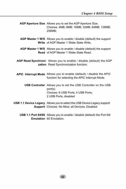
USB Controller Allows you to set the USB Controller on the USBport(s).Choices: 6 USB Ports; 4 USB Ports;2 USB Ports; disabled
USB 1.1 Device LegacySupport
Allows you to select the USB Device Legacy support.Choices: No Mice; all Devices; Disabled
USB 1.1 Port 64/60Emulation
Allows you to enable / disable (default) the Port 64/60 Emulation.
AGP Aperture Size Allows you to set the AGP Aperture Size.Choices: 4MB; 8MB; 16MB; 32MB; 64MB; 128MB;256MB;
AGP Master 1 W/SWrite
Allows you to enable / disable (default) the supportof AGP Master 1 Waite State Write.
AGP Master 1 W/SRead
Allows you to enable / disable (default) the supportof AGP Master 1 Waite State Read.
AGP Read Synchroni-zation
Allows you to enable / disable (default) the AGPRead Synchronization function.
APIC Interrupt Mode Allows you to enable (default) / disable the APICfunction for selecting the APIC interrupt Mode.

62
KT400-C
4-6.5 Power Management Features
3. Press <ESC> to return to the Main Menu when you finish setting upall items. The following item descriptions are provided as a quickguide to your setup.
Power Management Features allows you to set the system’s powersaving functions.
Run the Power Management Features as follows:
1. Choose “Power Management Features” from the Main Menu and alist of options will appear:
ACPI Standby State S1/POSPower Management/APM EnabledVideo Power Down Mode SuspendHard Disk Power Down Mode Stand ByStandby Time Out (Minute) DisabledSuspend Time Out (Minute) DisabledPower Button Function On/OffRestore on AC/Power Loss Last StateResume On PME# DisabledResume On PS/2 KB Disabled Wake-Up Key Any KeyResume On PS/2 Mouse DisabledResume On RTC Alarm DisabledRTC Alarm Date 15RTC Alarm Hour 12RTC Alarm Minute 30
Power Management Features Setup Help
AMIBIOS NEW SETUP UTILITY - VERSION 3.31a
2. Use one of the arrow keys to move between options and modify theselected options by using PgUp / PgDn / + / - keys. An explanationof the <F> keys follows:
<F1>: “Help” gives options available for each item.<F9>: Setup BIOS default values.<F10>: Save and Exit Setup.
F1: Help : Select Item +/- : Change Values F9: Setup DefaultsEsc: Previous Menu Enter: Select Sub-Menu F10: Save and Exit

63
Chapter 4 BIOS Setup
ACPI Standby State This item allows you to select the ACPI Suspendtype. You can select S3(STR) for suspending toDRAM if your system supports this mode. Or youcan select S1 (POS) for Power on Suspend underWindows 98 or later O/S ACPI mode..
Restore on AC/PowerLoss
Allows you to set the restore state from AC/PowerLoss.Choices: Last State; Power Off; Power On
Power Management/APM
Allows you to enable / disable the Power manage-ment / Advanced Power Management function.
Video Power DownMode
Allows you to select the Video Power Down Mode.Choices: Disabled; Stand By; Suspend
Hard Disk PowerDown Mode
Allows you to select the Hard Disk Power DownMode.Choices: Disabled; Stand By; Suspend
Standby Time Out(Minute)
To set the duration of Standby Time Out.Choices: 1; 2; 4; 8; 10; 20; 30; 40; 50; 60
Suspend Time Out(Minute)
To set the duration of Suspend Time Out.Choices: 1; 2; 4; 8; 10; 20; 30; 40; 50; 60
Power Button Function Allows you to set Power Button function.Choices: On/Off; Suspend
Resume on PME# Allows you to enable / disable the Resume on PMEfunction.
Resume on PS/2 KB Allows you to select S3/S4/S5 mode or disable theResume on Keyboard clock function.Choices: Disabled; S4/S5
Wake Up Key If Resume On KBC is not disabled, this item allowsyou to select any key to wake up system.
Resume on PS/2Mouse
Allows you to S4/S5 mode or disable the Resumeon PS/2 Mouse function.

64
KT400-C
Resume On RTC Alarm Allows you to enable / disable the Resume On RTCAlarm function.
RTC Alarm Date / Hour/ Minute
If resume On RTC Alarm is enabled, this field al-lows you to set the Alarm date Hour, Minute andsecond.Date Choices: Every Day; 01 ~ 31Hour Choices: 00 ~ 23Minute Choices: 00 ~ 59

65
Chapter 4 BIOS Setup
PNP/PCI Configuration allows you to modify the system’s power savingfunctions.
Run the PNP/PCI Configurations as follows:
1. Choose “PNP/PCI Configurations” from the Main Menu and a screenwith a list of options will appear:
4-6.6 PNP / PCI Configurations
3. Press <ESC> to return to the Main Menu when you finish setting upall items. The following item descriptions are provided as a quickguide to your setup.
AMIBIOS NEW SETUP UTILITY - VERSION 3.31a
Plug and Play Aware O/S NoClear NVRAM NoPCI Latency Timer (PCI Clocks) 32Primary Graphics Adapter PCIPCI IDE BusMaster EnabledPCI Slot1 IRQ Priority AutoPCI Slot2 IRQ Priority AutoPCI Slot3 IRQ Priority AutoPCI Slot4 IRQ Priority AutoPCI Slot5 IRQ Priority Auto
PNP/PCI Configurations Setup Help
2. Use one of the arrow keys to move between options and modify theselected options by using PgUp / PgDn / + / - keys. An explanationof the <F> keys follows:
<F1>: “Help” gives options available for each item.<F9>: Setup BIOS default values.<F10>: Save and Exit Setup.
F1: Help : Select Item +/- : Change Values F9: Setup DefaultsEsc: Previous Menu Enter: Select Sub-Menu F10: Save and Exit

66
KT400-C
PCI Latency Timer (PCIClocks)
Allows you to set the PCI Latency Time.Choices: 32; 64; 96; 192; 128; 160; 192; 224; 248;
PCI Slot 1/2/3/4/5 IRQPriority
Allows you to specify the IRQ for the PCI slots.Choices: Auto; 3; 4; 5; 7; 9; 10; 11
Clear NVRAM Allows BIOS to clear the NVRAM data.Choices: No (default); Yes
Primary GraphicsAdapter
Allows you to select the primary Graphics Adapter.Choices: PCI; AGP
PCI IDE BusMaster Allows you to enable / disable the PCI IDE BusMaster function.
Plug and Play AwareO/S
Allows BIOS to recognize the Plug and Play AwareOperating System.Choices: No (default); Yes

67
Chapter 4 BIOS Setup
Integrated Peripherals option allows you to get some information insideyour system when it is working.
Run the Integrated Peripherals as follows:1. Choose “Integrated Peripherals” from the Main Menu and a list of
options will appear:
4-6.7 Integrated Peripherals
3. Press <ESC> to return to the Main Menu when you finish setting upall items. The following item descriptions are provided as a quickguide to your setup.
AMIBIOS NEW SETUP UTILITY - VERSION 3.31a
Onboard FDC AutoOnboard Serial Port 1 AutoOnboard Serial Port 2 Auto Serial Port 2 Mode NormalOnboard Parallel Port Auto Parallel Port Mode ECP Parallel Port IRQ Auto Parallel Port DMA Channel AutoOnboard MIDI Port Disabled MIDI Port IRQ 5Onboard Game Port 200Onboard IDE BothOnboard AC’97 Audio Enabled
Integrated Peripherals Setup Help
2. Use one of the arrow keys to move between options and modify theselected options by using PgUp / PgDn / + / - keys. An explanationof the <F> keys follows:
<F1>: “Help” gives options available for each item.<F9>: Setup BIOS default values.<F10>: Save and Exit Setup.
F1: Help : Select Item +/- : Change Values F9: Setup DefaultsEsc: Previous Menu Enter: Select Sub-Menu F10: Save and Exit

68
KT400-C
Onboard MIDI Port Allows you to configure onboard MIDI port address.The choices: Disabled; 300h; 310h; 320h; 330h
MIDI Port IRQ If the onboard MIDI port is enabled, this item showsup to allow you to configure the MIDI Port IRQ toIRQ 5.
Onboard Game Port Allows you to configure Onboard Game portaddress.The choices: Disabled; 200h; 208h
Onboard Parallel Port Allows you to configure onboard Parallel port .Choices: Auto; Disabled; 378; 278; 3BC;
Parallel Port Mode If Parallel Port is not disabled, this item allows youto configure parallel port mode.Choices: ECP; EPP + ECP; Normal; EPP
Parallel Port IRQ If Parallel Port Mode is set at EPP, this item allowsyou to set the Parallel Port IRQ.Choices: 5; 7
Parallel Port DMAChannel
If Parallel Port Mode is set at ECP, this item allowsyou to set the DMA Channel.Choices: 0; 1; 3
Onboard FDC Allows you to enable / disable the Onboard FDC.Choices: Auto; Enabled; disabled
Onboard Serial Port 1
Serial Port 2 Mode Allows you to set the Serial Port B Mode.Choices: Normal; IrDA; ASKIR;
Allows you to set the Onboard Serial Port A.Choices; auto; Disabled; 3F8/COM1; 2F8/COM2;3E8/COM3; 2E8/COM4;
Onboard Serial Port 2 Allows you to set the Onboard Serial Port B.Choices; auto; Disabled; 3F8/COM1; 2F8/COM2;3E8/COM3; 2E8/COM4;

69
Chapter 4 BIOS Setup
Onboard IDE Allows you to choose the Onboard IDE Mode.Choices: Disabled; Primary; Secondary; Both
Onboard AC‘97 Audio Allows you to disable or set AC’97 Audio automati-cally by system.Choices: Auto; Disabled

70
KT400-C
This menu helps you to read only and get more information on theworking CPU temperature, FAN speed and voltage.
1. Choose “SmartDoc Anti-Burn Shield” from the Main Menu and ascreen with a list of current status of your working system will appear:
4-6.8 SmartDoc Anti-Burn Shield
AMIBIOS NEW SETUP UTILITY - VERSION 3.31a
CPU Warning Temperature DisabledCPU Shut Down Temperature DisabledCPU Fan Low speed Warning DisabledCPU Fan Low Speed Shutdown (Disabled)(ABSII)CPU Current Temperature (53 0C/1270F)(ABSII)CPU Shutdown Temperature 85 0C/185 0FTemperature 1 (31 0C/87 0F)Temperature 2 N/AFan 1 Speed (5443 RPM)Fan 2 Speed (0 RPM)Vcore (+1.680 V)+2.5V (+2.504 V)+3.3V (+3.408 V)+5.0V (+5.126 V)+12.0V (+11.187V)-12.0V (-11.972V)5V SB (+5.164V)Battery (+3.296V)
SmartDoc Anti-Burn Shield Setup Help
F1: Help : Select Item +/- : Change Values F9: Setup DefaultsEsc: Previous Menu Enter: Select Sub-Menu F10: Save and Exit
3. Press <ESC> to return to the Main Menu when you finish setting upall items. The following item descriptions are provided as a quickguide to your setup.
2. Use one of the arrow keys to move between options and modify theselected options by using PgUp / PgDn / + / - keys. An explanationof the <F> keys follows:
<F1>: “Help” gives options available for each item.<F9>: Setup BIOS default values.<F10>: Save and Exit Setup.
CPU Warning Tem-perature
Select a upper limits for the CPU temperature. Ifthe CPU temperature extends beyond the limit,any warning mechanism programmed into your sys-tem will activate the warning.

71
Chapter 4 BIOS Setup
CPU Shutdown Tem-perature
This feature allows you to set the shutdown tem-perature to the running CPU.Choices: Disabled; 50 0C~710C in 3˚ C stepping
CPU Fan Low SpeedWarning
This feature allows you to set up the CPU Fan LowSpeed warning function.Choices: Disabled; Stop/0RPM; 1000~6000RPM
ABS II CPU CurrentTemperature(for
Athlon XP/DuronMorgan)
This item will appear if Athlon XP or Duron MorganCPU is running on board. This item is to show thecurrent temperature inside the running CPU.
CPU Fan Low SpeedShutdown
This feature allows you to enable/disable the CPUFan Low Speed Shutdown function.Choices: Disabled; Stop/0RPM; 1000~6000RPM
ABS II CPU ShutdownTemperature(for
Athlon XP/DuronMorgan)
This item will appear if Athlon XP or Duron MorganCPU is running on board. ABS II (Anti-burn ShieldII) allows user to set up the safeguard temperaturefor the CPU designed with a protective thermal di-ode inside the CPU itself. Default Safeguard tem-perature is 85˚C, at which the XP or Duron MorganCPU will shutdown. Usually, a jumper is also de-signed on board for enabling/disabling ABS IIfunction.Choices: 75˚C / 167˚F; 80˚C / 176˚F 85˚C / 185˚F(default); 90˚C / 194˚F 95˚C / 203˚F; 100˚C / 212˚F
Temperature 1 Shows current CPU internal temperature.
Temperature 2 Shows current CPU external temperature.
Fan 1 / 2 Displays the current speed of CPU Fan, and otheronboard device which user has connected to theonboard Fan Connectors.
CPU Vcore Shows CPU core actual voltage value.
Battery Shows current voltage against battery power supply.
+2.5V/+3.3V/+5.0V/+12V/-12V/+5.V SB/
Shows current voltage against the respective powersupply.

72
KT400-C
Run the “Frequency/Voltage Control” as following:
1. Choose “Frequency/Voltage Control” from the Main Menu and ascreen with a list of options will appear:
4-6.9 Frequency/Voltage Control
3. Press <ESC> to return to the Main Menu when you finish setting upall items. The following item descriptions are provided as a quickguide to your setup.
AMIBIOS NEW SETUP UTILITY - VERSION 3.31a
Frequency/Voltage Control Setup Help
2. Use one of the arrow keys to move between options and modify theselected options by using PgUp / PgDn / + / - keys. An explanationof the <F> keys follows:
<F1>: “Help” gives options available for each item.<F9>: Setup BIOS default values.<F10>: Save and Exit Setup.
F1: Help : Select Item +/- : Change Values F9: Setup DefaultsEsc: Previous Menu Enter: Select Sub-Menu F10: Save and Exit
RedStorm Overclocking Tech (Optional)CPU Linear Frequency Disabled CPU Clock 100 MHzSpread spectrum DisabledAuto Detect PCI Slot Disabled
CPU Voltage Control AutoAGP Voltage Control 1.5VDIMM Voltage Control 2.5V
CPU Ratio Selection Default

73
Chapter 4 BIOS Setup
CPU RatioSelection
If CPU onboard is one with an adjustable or un-locked CPU ratio, this item allows you user to ad-just the CPU Ratio. If your CPU is one with theCPU Ratio locked, this item will be invalid.
CPU Linear Frequency
This item allows you to enable / disable this settingfunction.
CPU Clock If CPU Linear Frequency is set at Enabled, this itemallows you to set CPU Clock.Choices: 100MHz ~200MHz in 1MHz stepping.
CPU VoltageControl
allows you to configure the CPU Voltage. Usually,to raise CPU voltage will raise the chance of CPUoverclocking and yet risk damage of CPU.Choices: Auto; 1.100V ~1.850V in 0.025 stepping
AGP VoltageControl
allows you to configure the AGP Voltage.Choices: 1.5V; 1.6V; 1.7V; 1.8V
DIMM VoltageControl
allows you to configure the DIMM Voltage.Choices: 2.5V; 2.6V; 2.7V; 2.8V
Spread Spec-trum
Allows you to enable / disable this SpreadSpeectrum function. If enabled, this function willreduce the EMI (Electromagnetic Interference) inyour system. If you do not have an EMI problem,leave this item disabled.
(Optional)Redstorm Overclock-
ingTech
If this option is chosen in BIOS, press <Enter> tostart RED STORM OVERCLOCKING TECH. Thisoption helps user to raise CPU clock automaticallyuntil an unacceptable valueis reached. Then BIOSwill restart your systemwith a highest accept-able CPU clock.
Auto Detect PCI Slot Allows you to enable / disable the Auto Detect PCISlot function.

74
KT400-C
This menu helps you to read only and get more information on thesystem.
1. Choose “System Information” from the Main Menu and a screen witha list of current status of your working system will appear:
4-6.10 System Information
2. Press <ESC> to return to the Main Menu. In case any irregular read-ing appears about your system, it indicates that a problem existstherein. To solve the problem, a hardware engineer or your dealer isrecommended.
AMIBIOS NEW SETUP UTILITY - VERSION 3.31a
BIOS Version (12/03/02)Processor Type (AMD Duron(tm)Processor Speed (1300MHz)Base Memory (640KB)Extended Memory (255MB)Total Memory (256MB)Cache Size (192KB)Memory Bank 0 (SDRAM)Memory Bank 1 (SDRAM)Memory Bank 2 (None)
System Information Setup Help
F1: Help : Select Item +/- : Change Values F9: Setup DefaultsEsc: Previous Menu Enter: Select Sub-Menu F10: Save and Exit

75
Chapter 4 BIOS Setup
4-6.11 Set Supervisor Password
This option allows you to set a Supervisor password for the system:
1. Choose “Set Supervisor Password” in the Main Menu and press<Enter>. Then the following message appears:
[ Enter new supervisor password ]
2. The first time you run this option, enter your password up to 8 char-acters and press <Enter>. (The screen does not display the enteredcharacters.)
3. After you enter the password, the following message appears prompt-ing you to confirm the password:
[ Retype new supervisor Password ]
4. Enter the same password “exactly” the same as you have just typedto confirm the password and press <Enter>.
5. The following message appears to confirm the new password setup.
[ New supervisor password installed ]
Any Key to Continue
6. Then press any key to continue your CMOS Setup. To save the pass-word setup, you should press “Save & Exit Setup” and choose “yes”to exit and save setup.
7. After the Supervisor password is set, you have to choose whetherthe password is for entering the system or only for entering BIOSSetup program. To make the choice, please enter BIOS Setup andchoose “Advanced BIOS Features” in the main menu. (At enteringBIOS Setup, you have to enter the password now.) In “AdvancedBIOS Features”, choose “Password Check” and change the option.The “Setup” option is to set the password only for entering BIOSSetup. The “Always” option is to set the password for entering thesystem.

76
KT400-C
NOTE: If you forget or lose a supervisor password, the onlyway to access the system is to clear the CMOS. All setupinformations will then be cleared including the password andyou need to run the BIOS setup program again so as toreconfigure BIOS.
[ Enter current supervisor password ]
8. To change or remove a current supervisor password, choose “SetSupervisor Password” and press <Enter>. An instruction box appearson the screen, prompting you to enter the current password first:
9. Type the current password with keyboard and then press <Enter>.An instruction box appears, prompting you to enter new supervisorpassword:
[ Enter new supervisor password ]
10. If you enter a new password into the box, you will be using this newpassword after you have finished and saved this new setup. Instead,if you press <Enter> before you enter any new password into theinstruction box, another message box appears, telling you that youhave disabled the Supervisor password. That means, no passwordis set for either entering BIOS Setup or system:
[ Supervisor password disabled ]
Any Key to Continue

77
Chapter 4 BIOS Setup
When you press <Enter> on this item, you will get a confirmation dialog box with a message similar to:
Press <Enter> now to load Optimal values for all the Setup options.
4-6.14 Exit Without SavingExit Without Saving option allows you to exit the Setup Utility withoutsaving the modifications that you have specified. Highlight this optionon the Main Menu and the following message appears:
Follow the message and press <Enter> key to exit CMOS Setup andrestart system.
[ Quit Without Saving Changes ]
Press [Enter] to continueor [ESC] to abort
4-6.12 Load Optimized Defaults
[ Load Optimized Settings ]
Press [Enter] to continueor [ESC] to abort
4-6.13 Save & Exit Setup
Save & Exit Setup allows you to save all modifications you have specifiedinto the CMOS memory. Highlight this option on the Main Menu andpress <Enter>. The following message appears:
Press <Enter> key to save the configuration changes and exit CMOSSetup to restart your system.
[ Saving current settings and exit ]
Press [Enter] to continueor [ESC] to abort