ks 1876-2-2010, overhead power lines for kenya - safety
TRANSCRIPT
Draf
t Ken
ya S
tand
ard
for B
allot
ing —
Not
to b
e Ci
ted
as K
enya
Sta
ndar
d
KENYA STANDARD KS 1876-2:2010 ICS 29.260.20
© KEBS 2010 First Edition 2010
Electrical power transmission and distribution — Overhead power lines for conditions prevailing in Kenya — Part 2: Safety
BALLOT DRAFT, MAY 2010

Draf
t Ken
ya S
tand
ard
for B
allot
ing —
Not
to b
e Ci
ted
as K
enya
Sta
ndar
d
KS 1876-2:2010
ii © KEBS 2010 — All rights reserved
TECHNICAL COMMITTEE REPRESENTATION The following organizations were represented on the Technical Committee: Nairobi City Council, City Engineer’s Department. Jomo Kenyatta University of Agriculture and Technology Kenya Polytechnic Kenya Power & Lighting Company Fluid & Power Systems Ltd Ministry of Public Works and Housing Ministry of Energy Kenafric Industries Ltd Power Technics Ltd Rural Electrification Authority The Energy Regulatory Commission Consumer Information Network Kenya Association of Manufacturers Institute of Engineers of Kenya Kenya Electricity Generating Company Ltd ABB LTD Switchgear & Controls Ltd Power Controls Ltd Communications Communication of Kenya Instrument Ltd Kenya Pipeline Company Ltd Telkom Kenya Ltd Meteorological Department Kenya Bureau of Standards — Secretariat
REVISION OF KENYA STANDARDS In order to keep abreast of progress in industry, Kenya standards shall be regularly reviewed. Suggestions for improvement to published standards, addressed to the Managing Director, Kenya Bureau of Standards, are welcome.
© Kenya Bureau of Standards, 2010 Copyright. Users are reminded that by virtue of Section 25 of the Copyright Act, Cap. 12 of 2001 of the Laws of Kenya, copyright subsists in all Kenya Standards and except as provided under Section 26 of this Act, no Kenya Standard produced by Kenya Bureau of Standards may be reproduced, stored in a retrieval system in any form or transmitted by any means without prior permission in writing from the Managing Director.

Draf
t Ken
ya S
tand
ard
for B
allot
ing —
Not
to b
e Ci
ted
as K
enya
Sta
ndar
d
KENYA STANDARD KS 1876-2:20109 ICS 29.260.20
© KEBS 2010 — All rights reserved iii
Electrical power transmission and distribution — Overhead power lines for conditions prevailing in Kenya — Part 2: Safety
KENYA BUREAU OF STANDARDS (KEBS)
Head Office: P.O. Box 54974, Nairobi-00200, Tel.: (+254 020) 605490, 69028000, 602350, Mobile: 0722202137/8, 0734600471/2;
Fax: (+254 020) 604031 E-Mail: [email protected], Web:http://www.kebs.org
KEBS Coast Region P.O. Box 99376, Mombasa 80100 Tel: (+254 041) 229563, 230939/40 Fax: (+254 041) 229448 E-mail: [email protected]
KEBS Lake Region P.O. Box 2949, Kisumu 40100 Tel: (+254 057) 23549,22396 Fax: (+254 057) 21814 E-mail: [email protected]
KEBS North Rift Region P.O. Box 2138, Nakuru 20100 Tel: (+254 051) 210553, 210555

Draf
t Ken
ya S
tand
ard
for B
allot
ing —
Not
to b
e Ci
ted
as K
enya
Sta
ndar
d
KS 1876-2:2010
iv © KEBS 2010 — All rights reserved
F O R E W O R D
This Kenya standard was prepared by the Switchgear and Distribution Equipment in accordance with the procedures of the Bureau and is in compliance with Annex 3 of the WTO/TB Agreement. This part of this Kenya Standard has been prepared to enable competent persons to design safe and cost-effective overhead power lines by indicating the current technology and practices related to Kenyan conditions. This standard identifies the parameters to be considered in relation to safety and indicates internationally accepted references by which the values of these parameters can be determined. In the development of this standard, SANS 10280-1:2008, Overhead power lines for conditions prevailing in South Africa — Part 1: Safety, was extensively consulted. Assistance derived from this source is hereby acknowledged. Normative and informative annexes A 'normative' annex is an integral part of a standard, whereas an 'informative' annex is only for information and guidance. Summary of development
This Kenya Standard, having been prepared by the Switchgear and Distribution Equipment Technical Committee was first approved by the National Standards Council in June 2010
Amendments issued since publication
Amd. No. Date Text affected
Draf
t Ken
ya S
tand
ard
for B
allot
ing —
Not
to b
e Ci
ted
as K
enya
Sta
ndar
d
KS 1876-2:2010
© KEBS 2010 — All rights reserved v
Contents
1 Scope .................................................................................................................................................... 1
2 Normative references ........................................................................................................................... 1
3 Terms, definitions and abbreviations .................................................................................................... 1
3.1 Terms and definitions ........................................................................................................................... 1
3.2 Abbreviations ........................................................................................................................................ 2
4 Determination of mechanical loads ...................................................................................................... 2
4.1 General ................................................................................................................................................. 2
4.2 Simplified method ................................................................................................................................. 2
4.3 Detailed method .................................................................................................................................... 6
4.4 Design loads of temporary structures for emergencies ...................................................................... 13
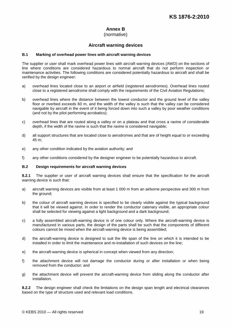
5 Aviation considerations — Application to the aviation authority (see foreword) ................................ 14
6 Waterway considerations — Application to the relevant authority ..................................................... 14
7 Conductor current rating (ampacity) ................................................................................................... 15
8 Clearances .......................................................................................................................................... 15
8.1 Vertical clearance to ground and structures ....................................................................................... 15
8.2 Horizontal clearances ......................................................................................................................... 15
9 Crossings ............................................................................................................................................ 16
9.1 Crossings over roads, railways, tramways and telecommunication lines .......................................... 16
9.2 Crossings between power lines .......................................................................................................... 16
9.3 Crossings over water .......................................................................................................................... 16
9.4 Crossings of service connections ....................................................................................................... 17
10 Step and touch potentials around earthing of power line towers and poles ....................................... 17
11 Warning signs ..................................................................................................................................... 17
Annex A (informative) Ice load incidents on overhead lines recorded in Kenya ............................................ 18
Annex B (normative) Aircraft warning devices................................................................................................ 19
Annex C (normative) Clearances required for power lines that cross services.............................................. 21
Annex D (normative) Directives on power lines and telecommunication circuits ........................................... 22

Draf
t Ken
ya S
tand
ard
for B
allot
ing —
Not
to b
e Ci
ted
as K
enya
Sta
ndar
d

Draf
t Ken
ya S
tand
ard
for B
allot
ing —
Not
to b
e Ci
ted
as K
enya
Sta
ndar
d
KENYA STANDARD KS 1876-2:2010
© KEBS 2010 — All rights reserved 1
Electrical power transmission and distribution — Ov erhead power lines for conditions prevailing in Kenya — Part 2: Safety 1 Scope This part of KS 1876 specifies the mechanical and electrical safety requirements of overhead power lines including requirements for supports, the conductor system, clearances and crossings. 2 Normative references The following referenced documents are indispensable for the application of this standard. For dated references, only the edition cited applies. For undated references, the latest edition of the referenced document (including any amendments) applies. 2.1 Standards IEC 60826:2003, Design criteria of overhead transmission lines ITU-T K.53, Values of induced voltages on telecommunication installations to establish telecom and a.c. power and railway operators responsibilities KS 516, Wood poles for power and telecommunications lines — Specification KS 1605, Specification for hardwood poles, droppers, laths, guardrail post and spacer blocks IEC 61466-1, Composite string insulator units for overhead lines with a nominal voltage greater than 1000 V — Part 1: Standard strength classes and end fittings 2.2 Other publications Cigré Working Group B2.12. Cigré Brochure 299. Guide for selection of weather parameters for bare overhead conductor ratings. 2006. Available from <ELT_144_3 on http://www.e-cigre.org>. Cigré Working Group SC 22.12. Probabilistic determination of conductor current ratings. EIectra No. 164, February 1996, pp. 103-119. Available from <ELT_144_3 on http://www.e-cigre.org>. Cigré Working Group SC 22.12. The thermal behaviour of overhead conductors — Section 1 and 2: Mathematical model for evaluation of conductor temperature in the steady state and the application thereof. Electra No. 144, October 1992, pp. 107-125. Available from <ELT_144_3 on http://www.e-cigre.org>. 3 Terms, definitions and abbreviations For the purposes of this document, the following terms, definitions and abbreviations apply. 3.1 Terms and definitions acceptable acceptable to the customer conductor current rating ampacity current which will meet the design, security and safety criteria of a particular line on which the conductor is used
Draf
t Ken
ya S
tand
ard
for B
allot
ing —
Not
to b
e Ci
ted
as K
enya
Sta
ndar
d
KS 1876-2:2010
2 © KEBS 2010 — All rights reserved
high public exposure area area that the public frequent on a daily basis proven method method that has been in practice for at least ten years without any known failure, or a method that uses internationally accepted calculation methods, or a method of testing that has been proven by acceptable testing authorities 3.2 Abbreviations ASL: at sea level BIL: basic insulation level RSL: residual static load UTS: ultimate tensile strength 4 Determination of mechanical loads 4.1 General Loads on the supports of lines of operating voltages 132 kV and lower may be determined by using either the simplified method in 4.2 or the detailed method in 4.3. For lines of operating voltage exceeding 132 kV, the detailed method shall be used. NOTE In the absence of detailed design data, the simplified method should be used. Users are cautioned not to use parts of the detailed method or parts of the simplified method. Only a single method should be chosen and followed. 4.2 Simplified method 4.2.1 General The simplified method incorporates experience of the successful history of the design, construction and operation of the overhead lines that were based on the previous edition of this document, into the design criteria based on the "limit state" concept (see 4.2.4). The previous approach, where the loads were compared to the component strength reduced by the factor of safety, has been replaced by the design approach, which uses a load and resistance format, which separates the effects of component strengths and their variability from the effects of external/loads and their uncertainty. Design criteria based on simplified calculation of the wind loads were calibrated with the weather data obtained from a statistical analysis for a 50 year return period. 4.2.2 Equation The following general limit state equation is used in the simplified method:
XYGYWR xxxnn ++≥ϕ
where ϕ is the appropriate strength factor, as given in Table 1, which takes into account variability of material,
workmanship, etc.; Rn is the nominal strength of the component, in newtons; Wn is the wind load relevant to each load condition, in newtons; Yx is the load factor that takes into account parameters such as variability of loads, importance of
structure and safety implications;

Draf
t Ken
ya S
tand
ard
for B
allot
ing —
Not
to b
e Ci
ted
as K
enya
Sta
ndar
d
KS 1876-2:2010
© KEBS 2010 — All rights reserved 3
Gx is the vertical dead load, in newtons; X is the applied load relevant to each load condition, in newtons (for example tension and additional
weight). 4.2.3 Strength factors for different material types The strength factors shall be applied to various material types in accordance with Table 1. 4.2.4 Limit states Load cases considered in the design of overhead lines are grouped into ultimate limit state and serviceability limit state cases. Ultimate limit state cases are those associated with load cases that lead to collapse, or with other similar forms of structural failure due to excessive deformation, loss of stability, overturning, rupture, buckling, etc. The load cases associated with these states are concerned with the safety of the public as well as the reliability of supports, foundations, conductors and hardware. Serviceability limit state cases are associated with load cases that will be sustained in a satisfactory manner by the structure and power line components without permanent deformation or damage. These load cases include vibration limits, support deflections and electrical clearances.
Table 1 — Strength factors to be applied
1 2 3 4
Component Limit state Strength factor ϕϕϕϕ
Strength verified by full -scale testing
Strength not verified by full -scale testing
Steel lattice structures and cross-arms Strength 1.0 0.8 Fabricated tubular steel poles and members Strength 1.0 0.8 Reinforced or pre-stressed concrete structures and members
Strength 1.0 0.9
Wood structures, poles or members (that comply with KS 516 and KS 1605)
Strength 0.7 or less (modulus of rupture) — Serviceability 0.3 (modulus of rupture) —
Line fittings, forged or fabricated Strength — 0.8 Line fittings, cast Strength — 0.7 Porcelain or glass insulators Strength — 0.8 Synthetic composite suspension or strain insulators Strength 0.5 (one minute mechanical
strength) —
Synthetic composite line post insulators Strength 0.9 (maximum design cantilever load)
—
Foundations (for soil nominations in the field) Strength 0.7 0.7 Conductors Strength 0.7 — Stay (cable) members Strength 0.7 —
4.2.5 Loads The calculated loads on a structure or on a component include conductor-imposed loads and the loads directly imposed on the structure or component. Conductor-imposed loads include conductor tensions, self-weight, wind loads, ice loads and forces due to line deviations. The loads directly imposed on a structure or a component include wind loads, ice loads, self-weight, construction loads and maintenance loads. The relevant loads that occur simultaneously are combined in accordance with the design situation considered and given in 4.2.6 as load cases. 4.2.6 Load cases — Ultimate limit state 4.2.6.1 Wind loads The structural components of an overhead line shall be designed for the joint effect of the following load combination:
CCSnn TGGWR 5.11.11.1 +++≥ϕ

Draf
t Ken
ya S
tand
ard
for B
allot
ing —
Not
to b
e Ci
ted
as K
enya
Sta
ndar
d
KS 1876-2:2010
4 © KEBS 2010 — All rights reserved
where ϕ is the appropriate strength factor, given in Table 1, which takes into account variability of material,
workmanship, etc.; Rn is the nominal strength of the components; in newtons; Wn is the wind load, based on the wind pressure in Table 2, in pascals; GS is the vertical dead load that results from the structure, in newtons; GC is the vertical dead load that results from the conductors and insulators, in newtons; TC is the conductor tension load produced by a healthy conductor subjected to a wind pressure of 880
Pa at a temperature of 15 °C, final condition, in n ewtons.
Table 2 — Wind pressure
1 2
Structure or component Wind
pressure Pa
Conductor and cylindrical objects (poles, insulators, etc.) 880
Supports of objects of rectangular cross-section 1900
Lattice towers of rectangular cross-section (projected area onwindward face(s) of the tower)
2850
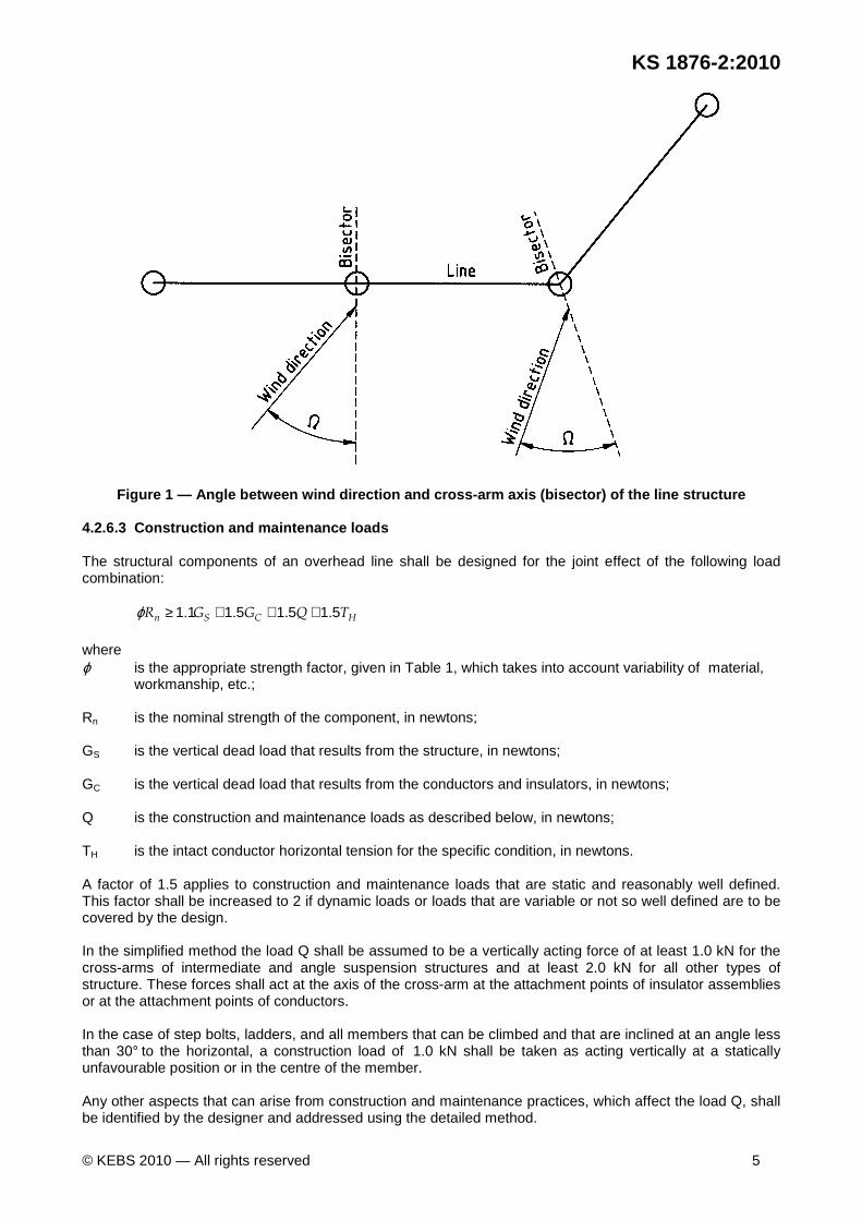
The wind direction shall be taken as being horizontal and acting perpendicularly to the surface exposed to the wind. In the case of asymmetrical structures, wind that acts from opposite directions shall be evaluated and the case that results in the worst load shall be considered. If the prevailing wind direction is not perpendicular to the surface being considered, the wind loads Wn given in Table 2 shall be multiplied by cos2
Ω where Ω is the angle between the wind direction and the bisector of the line structure (see Figure 1). Wind that acts at an angle of 45° to the cross-arm axis (bisector) of the line structure shall be considered for all types of towers and poles. 4.2.6.2 Ice loads Ice and snow accumulation on conductors and structures is not often experienced in Kenya; these conditions are associated with the high altitude areas of the country. Designers shall be aware of these areas (see Figure 2) and investigate unbalanced loads produced by ice that forms on conductors owing to local terrain topography (line sections with large adjacent span ratios in hilly terrains).
Draf
t Ken
ya S
tand
ard
for B
allot
ing —
Not
to b
e Ci
ted
as K
enya
Sta
ndar
d
KS 1876-2:2010
© KEBS 2010 — All rights reserved 5
Figure 1 — Angle between wind direction and cross-a rm axis (bisector) of the line structure 4.2.6.3 Construction and maintenance loads The structural components of an overhead line shall be designed for the joint effect of the following load combination:
HCSn TQGGR 51515111 .... +++≥ϕ where ϕ is the appropriate strength factor, given in Table 1, which takes into account variability of material,
workmanship, etc.; Rn is the nominal strength of the component, in newtons; GS is the vertical dead load that results from the structure, in newtons; GC is the vertical dead load that results from the conductors and insulators, in newtons; Q is the construction and maintenance loads as described below, in newtons; TH is the intact conductor horizontal tension for the specific condition, in newtons. A factor of 1.5 applies to construction and maintenance loads that are static and reasonably well defined. This factor shall be increased to 2 if dynamic loads or loads that are variable or not so well defined are to be covered by the design. In the simplified method the load Q shall be assumed to be a vertically acting force of at least 1.0 kN for the cross-arms of intermediate and angle suspension structures and at least 2.0 kN for all other types of structure. These forces shall act at the axis of the cross-arm at the attachment points of insulator assemblies or at the attachment points of conductors. In the case of step bolts, ladders, and all members that can be climbed and that are inclined at an angle less than 30° to the horizontal, a construction load of 1.0 kN shall be taken as acting vertically at a statically unfavourable position or in the centre of the member. Any other aspects that can arise from construction and maintenance practices, which affect the load Q, shall be identified by the designer and addressed using the detailed method.

Draf
t Ken
ya S
tand
ard
for B
allot
ing —
Not
to b
e Ci
ted
as K
enya
Sta
ndar
d
KS 1876-2:2010
6 © KEBS 2010 — All rights reserved
The maximum horizontal tension TH applied in the direction of the conductors shall be calculated for the conductors at 15 °C in still air in initial conditi ons (before creep). 4.2.6.4 Exceptional loads (failure containment) 4.2.6.4.1 General Dynamic loads on the structure owing to conductor breakage or failure of the adjacent structure are unpredictable, and the conductor's residual static load (RSL) shall be used to check structures for exceptional loads. For sub-transmission and distribution lines that use post insulators and relatively flexible structures, it is not necessary to specifically design intermediate (suspension) structures for the RSL load or broken conductor conditions. For more important lines, or where there is a concern that a cascading failure situation could develop, the designer shall consider using the detailed method for intermediate structures. In-line (section) strain, angle strain and terminal structures shall be checked for unbalanced load to provide rigid points in an overhead line. In the simplified method, the design loads shall be based on still air conditions with the joint effect of the following load combination:
BHCSn .... TTGGR 51511111 +++≥ϕ where ϕ is the appropriate strength factor, given in table 1, which takes into account variability of material,
workmanship, etc.; Rn is the nominal strength of the components, in newtons; GS is the vertical dead load that results from the structure, in newtons; GC is the vertical dead load that results from the conductors and insulators, in newtons; TH is the intact conductor horizontal tension for the specific condition, in newtons; TB is the unbalanced conductor tension load that results from abnormal conditions, for example, a
broken conductor, in newtons. 4.2.6.4.2 Loads due to broken conductors At any terminal or angle strain structure, a broken conductor condition introduces a torsional load as a result of the release of tension in one phase conductor while other healthy conductors are under the tension corresponding to the final condition with the conductor at a temperature of -5°C without any wind load . The above limit shall be tested with various phase conductors or with the earth wires, and the case that gives rise to the most unfavourable load conditions shall be considered. 4.2.6.4.3 Longitudinal unbalanced load at angle str ain and in-line strain structures Angle and in-line strain structures shall be dimensioned to resist a longitudinal unbalanced (cascading) load created by applying tension corresponding to the final condition (at conductor temperature of -5°C, wi thout any wind load), to all attachment points at the head span, and applying 60 % of this tension to the attachment points at the back span. 4.3 Detailed method 4.3.1 General Loads, which incorporate the following, shall be determined:
Draf
t Ken
ya S
tand
ard
for B
allot
ing —
Not
to b
e Ci
ted
as K
enya
Sta
ndar
d
KS 1876-2:2010
© KEBS 2010 — All rights reserved 7
a) wind loads; b) ice loads; c) construction loads; and d) failure containment loads. Loads shall be determined in accordance with IEC 60826. The requirements specified in 4.3 are intended to clarify and detail input requirements stipulated in IEC 60826, and therefore this part of KS 1876 shall be read in conjunction with that standard. Certain deviations and additions to IEC 60826 are reflected in the requirements below, and shall take precedence over IEC 60826 in the event of a dispute. 4.3.2 Reliability requirements In IEC 60826 the load on supports, modified by a load factor, is used to determine the minimum required strength of components, which may be modified by a strength factor, as follows:
CT FRYQ < where Y is the load factor, based on a minimum reliability level, linked to a return period; QT is the calculated load, in newtons; F is the strength factor, based on failure sequencing and strength coordination between components; RC is the characteristic strength of the component. The reliability levels of lines, selected in accordance with 5.1.1.1 of IEC 60826:2003 are as stipulated in Table 3.
Table 3 — Reliability levels
1 2 3 4
Voltage Minimum reliability level
Return period years
Load factor for wind YTW
Up to 132 kV 1 50 1.0 >132 kV to <400 kV 2 150 1.1 400 kV and greater 3 500 1.2
Where lines form the principle source of supply, the reliability level should be upgraded to the next higher category. NOTE The requirements in 4.3.2 do not apply to the design of temporary structures used for emergencies. 4.3.3 Wind loads 4.3.3.1 Design of supports The design of supports shall take into consideration the wind load cases specified in 4.3.3.2. During the application of such designs in the field, allowable wind spans may require adjustment due to specific terrain conditions in accordance with 4.3.3.2. 4.3.3.2 Wind loads on supports Wind loads shall be applied in various directions to the supports in accordance with the wind load cases
Draf
t Ken
ya S
tand
ard
for B
allot
ing —
Not
to b
e Ci
ted
as K
enya
Sta
ndar
d
KS 1876-2:2010
8 © KEBS 2010 — All rights reserved
given in Table 4 and Figure 3. In each of these wind load cases, wind loads on insulator strings (see 6.2.6.3 of IEC 60826:2003) and wind loads on supports (see 6.2.6.4 of IEC 60826:2003) shall be combined with wind loads on conductors (see 6.2.6.1 of IEC 60826:2003). 4.3.3.3 Narrow wind loads on chainette and light gu yed structures Structures that are not subjected to significant bending through cross-arms (such as chainette towers and guyed monopoles), shall be subjected to a narrow wind load case, applied only to the tower at an angle of 45° to the line, while everyday tensions and weight s are considered on the conductors. The basic wind speed considered in these cases shall be in accordance with table 6. The consideration paid to the effect of this wind is to ensure that the structure has a minimum level of rigidity to resist tornado wind loads. NOTE The narrow wind load case might not effectively yield a tornado-resistant tower, since failure during such climatic events is often caused by impact loads from wind-borne objects. For general conditions in South Africa, the wind load input parameters in table 5 shall be assumed.
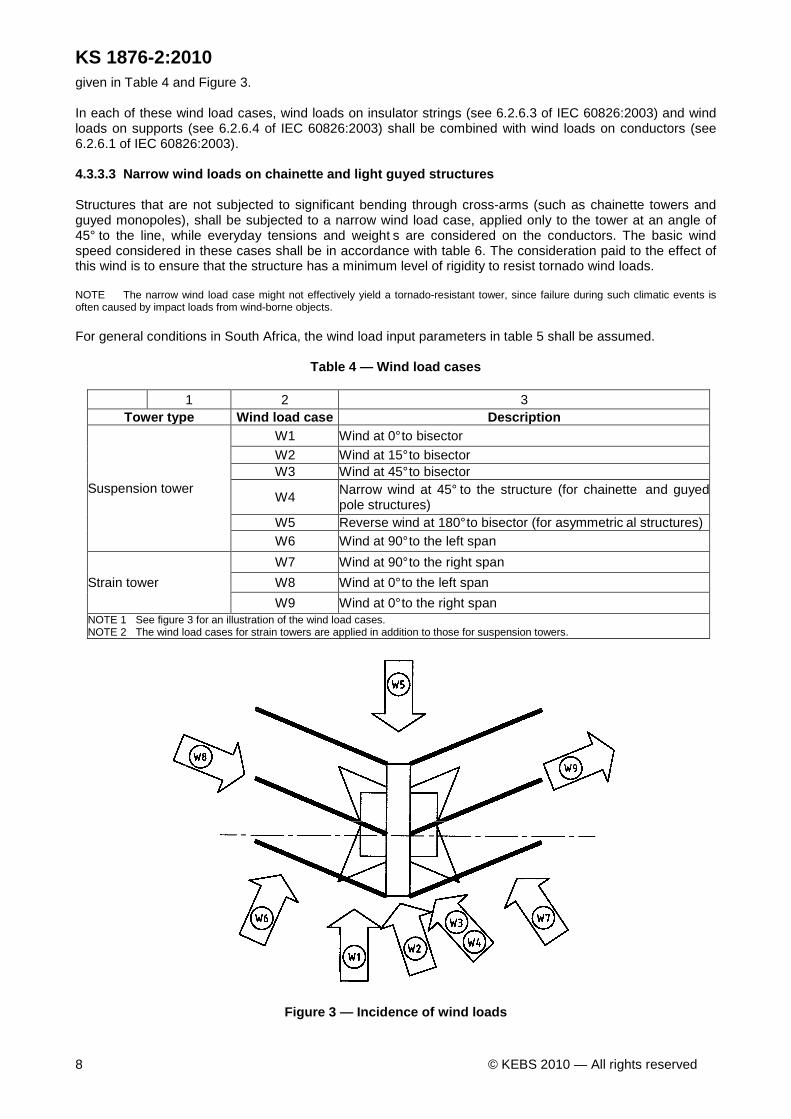
Table 4 — Wind load cases
1 2 3 Tower type Wind load case Description
Suspension tower
W1 Wind at 0° to bisector
W2 Wind at 15° to bisector W3 Wind at 45° to bisector
W4 Narrow wind at 45° to the structure (for chainette and guyed pole structures)
W5 Reverse wind at 180° to bisector (for asymmetric al structures) W6 Wind at 90° to the left span
Strain tower
W7 Wind at 90° to the right span
W8 Wind at 0° to the left span
W9 Wind at 0° to the right span NOTE 1 See figure 3 for an illustration of the wind load cases. NOTE 2 The wind load cases for strain towers are applied in addition to those for suspension towers.
Figure 3 — Incidence of wind loads

Draf
t Ken
ya S
tand
ard
for B
allot
ing —
Not
to b
e Ci
ted
as K
enya
Sta
ndar
d
KS 1876-2:2010
© KEBS 2010 — All rights reserved 9
Table 5 — Wind load input parameters
1 2 3 Parameter Input value IEC 60826 subclause
Terrain category B (Open country with few obstacles) 6.2.2 Reference (10 min) wind speed 28 m/s 6.2.3 Combination of wind speed andtemperature
Only consider high wind speed andreference temperature of 15 °C
6.2.4
Altitude 0 m ASL 6.2.5
Table 6 — Narrow wind loads applied to towers with no direct bending
1 2
Tower type Basic 10 min wind speed m/s
Suspension chainette 30 Guyed strain towers, guyed monopoles 40
4.3.3.4 Terrain-specific modification of wind span 4.3.3.4.1 Wind span reductions Allowable wind spans of structures, which were designed in accordance with the wind load cases given 4.3.3, require adjustment for certain terrain conditions. Calculate the allowable wind span Wa as follows:
tgda ωω ⋅⋅= WW
where Wa is the allowable wind span; Wd is the design wind span; ωg is the wind span reduction factor due to the geographical location (see Table 7); ωt is the wind span reduction factor due to the erection of structures in category A terrain (a large
stretch of water or upwind or flat coastal areas), or spans that traverse significant ridges, valleys or escarpments (see Table 8).
4.3.3.4.2 Reductions due to geographical location The ten minute reference wind speeds for specific areas can be adjusted in accordance with Figure 4 and Table 7. Where overhead lines traverse areas with ten minute wind speeds that exceed a 28 m/s wind as indicated in figure 4, allowable wind spans shall be reduced by the factors given in table 7.
Table 7 — Reduction of allowable wind span for geog raphical location
1 2 Ten minute reference wind speed Reduction factor (ωg)
m/s 28 1 32 0.75 35 0.65
4.3.3.4.3 Reductions due to topographical and terra in influences Since failures of overhead lines are also attributed to local terrain influences, the following location-specific wind span reduction factors are required where lines traverse the following areas:
Draf
t Ken
ya S
tand
ard
for B
allot
ing —
Not
to b
e Ci
ted
as K
enya
Sta
ndar
d
KS 1876-2:2010
10 © KEBS 2010 — All rights reserved
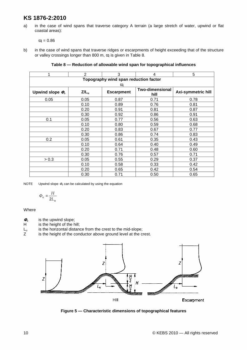
a) in the case of wind spans that traverse category A terrain (a large stretch of water, upwind or flat coastal areas):
ωt = 0.86
b) in the case of wind spans that traverse ridges or escarpments of height exceeding that of the structure
or valley crossings longer than 800 m, ωt is given in Table 8.
Table 8 — Reduction of allowable wind span for topo graphical influences
1 2 3 4 5 Topography wind span reduction factor
ωt
Upwind slope ΦΦΦΦe Z/Lu Escarpment Two-dimensional hill Axi-symmetric hill
0.05 0.05 0.87 0.71 0.78 0.10 0.89 0.76 0.81 0.20 0.91 0.81 0.87 0.30 0.92 0.86 0.91
0.1 0.05 0.77 0.56 0.63 0.10 0.80 0.59 0.68 0.20 0.83 0.67 0.77 0.30 0.86 0.74 0.83
0.2 0.05 0.61 0.35 0.43 0.10 0.64 0.40 0.49 0.20 0.71 0.48 0.60 0.30 0.76 0.57 0.71
> 0.3 0.05 0.55 0.29 0.37 0.10 0.58 0.33 0.42 0.20 0.65 0.42 0.54 0.30 0.71 0.50 0.65
NOTE Upwind slope Φe can be calculated by using the equation
ue
L
HΦ
2=
Where ΦΦΦΦe is the upwind slope; H is the height of the hill; Lu is the horizontal distance from the crest to the mid-slope; Z is the height of the conductor above ground level at the crest.
Figure 5 — Characteristic dimensions of topographic al features

Draf
t Ken
ya S
tand
ard
for B
allot
ing —
Not
to b
e Ci
ted
as K
enya
Sta
ndar
d
KS 1876-2:2010
© KEBS 2010 — All rights reserved 11
4.3.4 Ice loads Since the frequency of overhead line failures due to ice loads does not warrant detailed investigation, the calculation of ice loads shall be done in accordance with 6.3 of IEC 60826:2003 only, in which ice without wind is considered. See Annex A. Where overhead lines traverse the ice load risk areas indicated in Figure 2, a nominal additional load of 10 mm of radial ice shall be applied without wind, see 6.3.2 of IEC 60826:2003. This load shall be added to the dead load of the un-factored conductor self-weight, which might or might not result in a reduction of allowable weight spans over the area traversed. NOTE The nominal ice load will, in some instances, be less than construction safety loads — in which the dead weight of the conductor is usually multiplied by 2. Where overhead lines traverse terrain where there has been an instance of ice load failure, the radial ice thickness may be applied in accordance with observed known instances of line failures. When the radial ice thickness to be applied in such cases is being considered, consider the information given in Table A.1. Thus, towers can specifically be designed for ice loads. In an ice load case (only applicable to risk areas), consider the information given in Table A.1. It might also be deemed practicable to design structures for no ice load, and determine the net reduction in allowable weight span, which is applied during the tower spotting process. 4.3.5 Construction and maintenance loads The construction and maintenance load cases are relevant to the construction phase, when safety is the main consideration. Unless specifically catered for in the design, all strain structures (except terminal structures) from which stringing on one side is initiated, are back-stayed during stringing. Conductor tensions for construction load cases are based on stringing tensions, and the initial E-values (Young's modulus) of conductors. Maximum stringing tensions are calculated by using the following values with respect to the everyday conductor tension (the relevant conductor tension at 15 °C):
temperature: 0 °C (-15 °C from the reference tempe rature);
conductor E-values: initial E-values as specified by the conductor manufacturer.
A conductor tension factor of 2,0 for conductors being moved and 1.5 for all conductors in place shall be applied (see 6.5.3.1 of IEC 60826:2003). In conjunction with the stringing tensions, a vertical load factor of 2 shall be applied to the dead weight of all conductors (including spacers, conductor hardware and insulation), in accordance with 6.5.3.2 of IEC 60826:2003.
No wind pressure shall be considered during stringing (see 6.5.3.3 of IEC 60826:2003).
As a minimum, construction load cases under the following scenarios shall be determined:
load case 1 - stringing of first phase from longest cross-arm (no other conductors attached);
load case 2 - installation failure during regulation of last phase (tension factor of 2.0) and all other conductors in place (tension factor of 1.5); and
load case 3 - maintenance loads on temporary lifting points on the structure (such as lifting points for maintenance).
4.3.6 Exceptional loads (failure containment) 4.3.6.1 Broken conductor loads The object of designing for failure containment is to prevent cascading failures over a series of sequential structures. The assumption is that the full impact load of all phases can only partially be absorbed, implying that more than one structure might collapse before the cascading failure is contained.

Draf
t Ken
ya S
tand
ard
for B
allot
ing —
Not
to b
e Ci
ted
as K
enya
Sta
ndar
d
KS 1876-2:2010
12 © KEBS 2010 — All rights reserved
Suspension structures that support conductors of 132 kV and lower need not be designed for failure containment. For such lines, a strain structure capable of containing failure shall be placed at intervals not exceeding 5 km. Crossing over roads with strain structures for lower voltages shall be considered, to ensure that cascaded towers do not occur on roads. Static loads shall be applied at each attachment point (including all conductors and earthwires) on one longitudinal face of the structure, in accordance with 6.6.3.2 of IEC 60826:2003. The conductor tension shall be calculated assuming only the conductor self-weight (including all spacers, weights and in span attachments) under everyday, post-creep conditions, with no coincident wind. 4.3.6.2 Conventional suspension structures Suspended insulator arrangements will, in the event of complete conductor or adjacent structure failure, experience swung out conditions that will diminish away from the failure point. The net effect of such relaxation in conductor tension may be derived by adding half of the insulator length to the span length at everyday tension as illustrated in figure 6. The tension reduction on more complex suspension assemblies that carry all phases on a single suspended arrangement (such as suspended delta or chainette configurations), may be derived by adding half of the length from the axis of rotation to the centroid of conductors, to the span length at everyday tension as illustrated in Figure 6.
Key L is the catenary length
Figure 6 — Determination of increase in catenary le ngth for swung out conditions
4.3.6.3 Suspension structures with collapsible cros s-arms Suspension structures may be specifically designed to allow for the local failure of cross-arms, or post insulators at the tower body attachment, in order to relieve static tension. The net reduction in static tension may be derived by adding half of the post insulator or cross-arm length (in addition to half of the length of suspension assemblies as stipulated above) to the span at everyday tension. The loads shall be applied to the body of the superstructure, which shall be designed to contain the longitudinal load. 4.3.6.4 Strain structures In accordance with 6.6.3.3 of IEC 60826:2003, strain or terminal structures shall withstand greater resilience to impact loads. A factor of 1.5 shall be applied to the static everyday tension. However, it shall not be assumed that strain structures designed in accordance with this requirement will fully absorb impact loads, since experiments have revealed that impact loads can be as high as 2.5 times the everyday tension. The failure containment load case can thus be summarized as follows:
Draf
t Ken
ya S
tand
ard
for B
allot
ing —
Not
to b
e Ci
ted
as K
enya
Sta
ndar
d
KS 1876-2:2010
© KEBS 2010 — All rights reserved 13
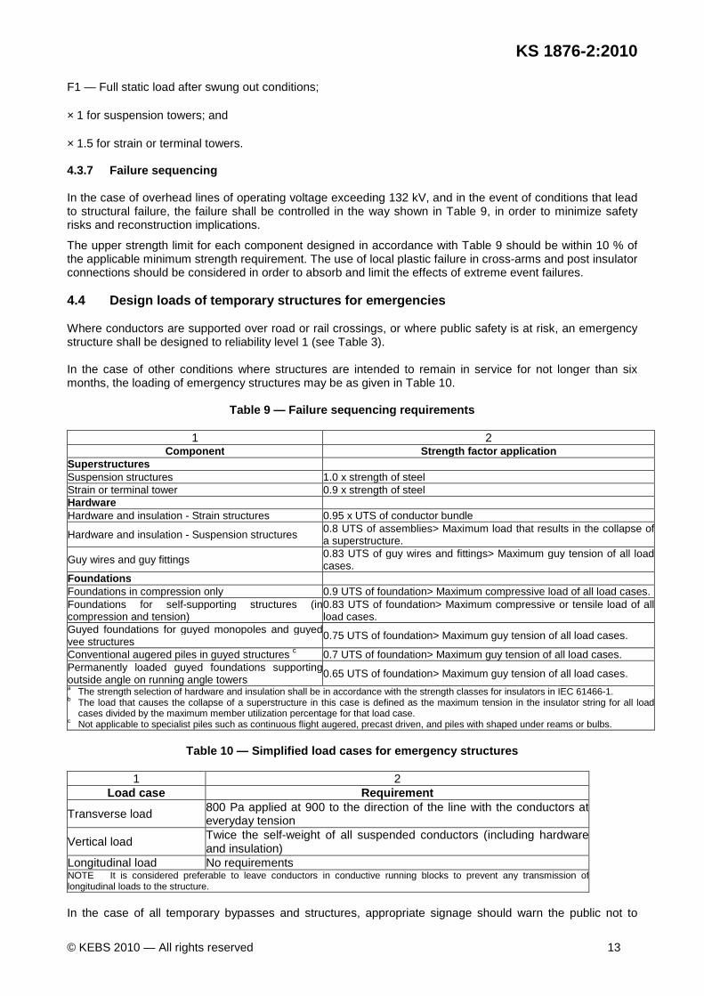
F1 — Full static load after swung out conditions; × 1 for suspension towers; and × 1.5 for strain or terminal towers. 4.3.7 Failure sequencing In the case of overhead lines of operating voltage exceeding 132 kV, and in the event of conditions that lead to structural failure, the failure shall be controlled in the way shown in Table 9, in order to minimize safety risks and reconstruction implications.
The upper strength limit for each component designed in accordance with Table 9 should be within 10 % of the applicable minimum strength requirement. The use of local plastic failure in cross-arms and post insulator connections should be considered in order to absorb and limit the effects of extreme event failures. 4.4 Design loads of temporary structures for emerge ncies Where conductors are supported over road or rail crossings, or where public safety is at risk, an emergency structure shall be designed to reliability level 1 (see Table 3). In the case of other conditions where structures are intended to remain in service for not longer than six months, the loading of emergency structures may be as given in Table 10.
Table 9 — Failure sequencing requirements
1 2 Component Strength factor application
Superstructures Suspension structures 1.0 x strength of steel Strain or terminal tower 0.9 x strength of steel Hardware Hardware and insulation - Strain structures 0.95 x UTS of conductor bundle
Hardware and insulation - Suspension structures 0.8 UTS of assemblies> Maximum load that results in the collapse of a superstructure.
Guy wires and guy fittings 0.83 UTS of guy wires and fittings> Maximum guy tension of all load cases.
Foundations Foundations in compression only 0.9 UTS of foundation> Maximum compressive load of all load cases. Foundations for self-supporting structures (in compression and tension)
0.83 UTS of foundation> Maximum compressive or tensile load of all load cases.
Guyed foundations for guyed monopoles and guyed vee structures
0.75 UTS of foundation> Maximum guy tension of all load cases.
Conventional augered piles in guyed structures c 0.7 UTS of foundation> Maximum guy tension of all load cases. Permanently loaded guyed foundations supporting outside angle on running angle towers 0.65 UTS of foundation> Maximum guy tension of all load cases. a The strength selection of hardware and insulation shall be in accordance with the strength classes for insulators in IEC 61466-1. b The load that causes the collapse of a superstructure in this case is defined as the maximum tension in the insulator string for all load
cases divided by the maximum member utilization percentage for that load case. c Not applicable to specialist piles such as continuous flight augered, precast driven, and piles with shaped under reams or bulbs.
Table 10 — Simplified load cases for emergency stru ctures
1 2
Load case Requirement
Transverse load 800 Pa applied at 900 to the direction of the line with the conductors ateveryday tension
Vertical load Twice the self-weight of all suspended conductors (including hardwareand insulation)
Longitudinal load No requirements NOTE It is considered preferable to leave conductors in conductive running blocks to prevent any transmission of longitudinal loads to the structure.
In the case of all temporary bypasses and structures, appropriate signage should warn the public not to
Draf
t Ken
ya S
tand
ard
for B
allot
ing —
Not
to b
e Ci
ted
as K
enya
Sta
ndar
d
KS 1876-2:2010
14 © KEBS 2010 — All rights reserved
approach the area of reconstruction. 5 Aviation considerations — Application to the avia tion authority (see foreword) 5.1 The supplier or user of an overhead line shall, in the early planning phase of such a power line route, identify potentially hazardous conditions for aircraft. 5.2 In a case where a potentially hazardous condition has been identified, the supplier or user shall consult with the aviation authority (see foreword). 5.3 The following documented information shall be submitted on request from the aviation authority (see foreword): a) the name of the power line; b) a map that indicates the power line route; c) a list of co-ordinates of all bend points (latitude and longitude, in degrees, minutes, seconds and tenths
of seconds); and d) the maximum height of the structures above ground level. 5.4 The aviation authority (see foreword) shall evaluate the route and require the supplier or user to mark or re-route those sections of the line (if any), that are considered a danger to aviation. The aviation authority may require that the supporting structures be marked by a specific marking pattern, or lighted by a combination of low- to high-intensity obstacle lights (or both). 5.5 Where overhead power lines cross a river which is wide enough to be navigable or a valley of such depth that it is considered to be navigable, the supplier or user shall provide the co-ordinates (latitude and longitude, in degrees, minutes, seconds and tenths of seconds) and the height of the line above the valley floor or water level, to the aviation authority (see foreword) for publication in the appropriate media. 5.6 Where required by the aviation authority (see foreword), the requirements in Annex B shall apply. Any deviation from these requirements shall be approved by the aviation authority. 6 Waterway considerations — Application to the rele vant authority NOTE Harbours and marinas are considered waterways. 6.1 Where practically possible, the supplier or user of an overhead line shall not make use of overhead lines over waterways and marinas. In the absence of alternative routes, the supplier or user shall identify, in the early planning phase of such a power line route, the potential hazardous conditions for marine craft. 6.2 Where hazards are identified, the supplier or user shall submit an official submission to the relevant authority (see foreword) on the identified hazards. The following documented information shall be included in the submission: a) the name of the power line; b) a map that indicates the power line route and possible hazards; c) a list of co-ordinates of all bend points (latitude and longitude, in degrees, minutes, seconds and tenths
of seconds); and d) the minimum clearance below the line from the highest expected water level (tide and five year flood
line). 6.3 The relevant authority (see foreword) shall evaluate the route and require the supplier or user to mark or re-route those sections of the line (if any), that are considered a danger to marine craft. The relevant authority may require that the supporting structures be marked by the application of a specific marking pattern, or lighted by a combination of low- to high-intensity obstacle lights (or both). 6.4 The relevant authority (see foreword) may also require the supplier or user of the overhead power

Draf
t Ken
ya S
tand
ard
for B
allot
ing —
Not
to b
e Ci
ted
as K
enya
Sta
ndar
d
KS 1876-2:2010
© KEBS 2010 — All rights reserved 15
line to limit approaching marine craft from making contact with the power line by applying overhead barriers. 6.5 Minimum vertical clearance of overhead power lines to rivers and dams that do not form part of waterways shall be in accordance with 9.3. 6.6 The supplier or user of the power line together with the owner of the waterway shall take joint responsibility for ensuring that any marking or barriers are installed and maintained. 7 Conductor current rating (ampacity) 7.1 Conductor current ratings (ampacity) can be determined by either assuming the worst case cooling conditions (deterministic method) or by assessing the risk of an unsafe condition that arises (probabilistic method). 7.2 In the case of deterministic ratings, the weather assumptions shall be with regard to bare overhead conductor ratings.
The weather parameters are:
wind speed perpendicular to line 0.6 m/s;
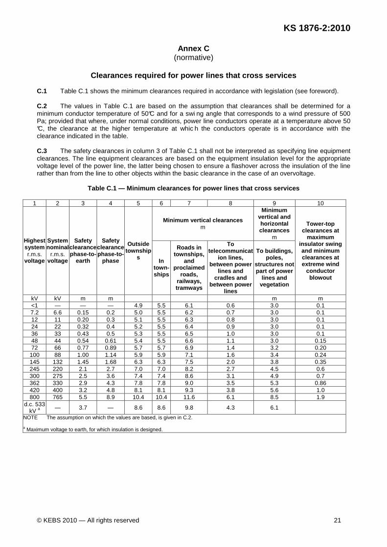
absorptivity and emissivity 0.8; solar radiation 1 000 w/m2; ambient temperature 40 °C. 7.3 The deterministic ampacity calculations shall be performed based on the equations found in the article titled The thermal behaviour of overhead conductors Section 1 and 2: Mathematical model for evaluation of conductor temperature in the steady state and the application thereof. (Article in the Cigré publication, Electra, No. 144). 7.4 In the case of the deterministic method, the templating or design temperature of the line is the temperature that shall be used in the calculation of the current. 7.5 If the probabilistic method is used, it shall be performed in accordance with the article titled Probabilistic Determination of Conductor Current Ratings. (Article in the Cigré publication Electra. No. 164). 7.6 The current ratings in different geographical areas with different weather conditions and different load profiles shall not result in the probability of an unsafe condition arising that is higher than the highest probability that already exists in areas in which lines are in operation. Based on current analysis, the probability of an unsafe condition arising shall be not higher than 6 × 10⁻⁶ for normal operating conditions. 7.7 Designers shall ensure that the temperatures, which the conductors are likely to reach, shall not have a detrimental effect on the safety of the public who relate to the operation of the line. 8 Clearances 8.1 Vertical clearance to ground and structures
The minimum vertical clearance above ground or to a structure is in accordance with the values in columns 5 to 9 in Table C.1. The conditions at which the clearance shall be determined shall be
a) at maximum conductor blow-out (at a wind pressure of 880 Pa and an air temperature of 15 °C);
b) at a maximum operating temperature of at least 50 °C with a wind pressure of 550 Pa. 8.2 Horizontal clearances 8.2.1 Except in the case of low-voltage lines of insulated wire of a type approved by the machinery authority (see foreword), the horizontal clearances between any live conductor and buildings, poles, structures and vegetation which are not part of power lines, shall be in accordance with
a) column 10 of Table C.1 in the case of maximum conductor blow-out at extreme wind at 15 °C but not less than 880 Pa; and

Draf
t Ken
ya S
tand
ard
for B
allot
ing —
Not
to b
e Ci
ted
as K
enya
Sta
ndar
d
KS 1876-2:2010
16 © KEBS 2010 — All rights reserved
b) column 9 of Table C.1 in the case of maximum operating temperature but not less than 50 °C and wind of 500 Pa.
NOTE 1 Extreme wind refers to a return period of at least 50 years. 8.2.2 In the case where the overhead power line conductor can be approached from buildings, poles, structures and vegetation which are not part of power lines, the clearance shall be in accordance with column 9 of Table C.1 for maximum conductor blow-out at 15 °C and at extreme wind not less than 880 Pa . 8.2.3 The horizontal distance of objects, including vegetation, likely to fall onto an overhead line conductor, shall be limited by the height of such object. 9 Crossings 9.1 Crossings over roads, railways, tramways and te lecommunication lines 9.1.1 The line design shall ensure that the crossing span is not adversely jeopardized by joints in the span whether they be tee, terminal or in-line joints. 9.1.2 The line shall be designed to ensure that the likelihood of the conductor or subconductor burning down in a crossing is minimized. This can be achieved by the use of arcing horns, or armour rods, or proven methods (see 3.1). 9.1.3 The line shall be so designed as to ensure that damage to the line conductors adjacent to the crossing cannot jeopardize the integrity of the crossing span. 9.1.4 If the crossing span is strained off at each end, the crossing will not be affected by damage to the conductors beyond the crossing. It is, therefore, unnecessary to fit arcing horns or armour rods to the live end of insulators on strain or intermediate structures beyond the crossing span. In the crossing span itself, however, arcing horns are required where the conductor could be burnt off in the event of a flashover. 9.1.5 Conventional armour rods shall not be used where the conductor is secured to a rigid insulator by means of a preformed tie, because in the event of a breakage, the conductor can slide through the ungritted armour rods and the crossing span clearance would consequently be reduced to below the minimum of 4.5 m. To overcome this problem, a full-wrap preformed twin tie shall be used, which, in addition to fixing the conductor securely to the rigid insulator, also protects the conductor against damage in the event of flashover. 9.1.6 In the absence of a mutually acceptable agreement between the power utility and the tele-communications network service licensee on line crossing angles, Table D.2 shall be used. 9.2 Crossings between power lines The clearance between power lines shall be determined using the worst physical case (largest separation) of the two lines crossing, considering the maximum operating temperature of the top line and the cold condition of the bottom line.
The clearance values to be maintained shall correspond to the values in Table C.1 for the higher voltage line given in
a) column 4 of Table C.1 in the case of conductor crossing over conductor; and
b) column 8 of Table C.1 in the case of a conductor that crosses over or in close proximity of the structure.
9.3 Crossings over water In general, normal ground clearances shall be provided. However, where crossings are made over rivers, dams or lakes, which are, or could be, used as recognized sailing waters, a clearance of 2.5 m plus the relevant minimum outdoor clearance (see Annex C) shall be provided over the tallest boat mast likely to be encountered on such water under conditions of normal high-water level and maximum conductor sag. The tallest boat mast to be encountered on inland waters is not likely to exceed 15.5 m. Checks should, however, be carried out for the particular stretches of water that are to be crossed.
Draf
t Ken
ya S
tand
ard
for B
allot
ing —
Not
to b
e Ci
ted
as K
enya
Sta
ndar
d
KS 1876-2:2010
© KEBS 2010 — All rights reserved 17
9.4 Crossings of service connections 9.4.1 Power service connection cables that cross bare telecommunication lines shall maintain a separation distance of at least 0.9 m at attachment points and 0.5 m at mid-span, and shall not cross below bare telecommunication services. 9.4.2 Provided that the power service connection cable is concentric or armoured and crosses non-bare telecommunication lines, the following shall apply.
a) The power and telecommunication service connection cables may be secured at common attachment points on structures that support only service connection cables and at the service termination. Precautions shall be taken to prevent mechanical damage to either service connection cable.
b) The power service connection cable may cross a telecommunication service connection cable (either above or below it) and may be attached to the telecommunication authority's (see foreword) structure, provided that the separation distance at the crossing point is at least 0.2 m.
9.4.3 Other power service connection cables (e.g. non-concentric or unarmoured) shall maintain a separation distance of at least 0.9 m at attachment points and 0.2 m at mid-span. 10 Step and touch potentials around earthing of pow er line towers and poles 10.1 The tower and the down conductors on structures made of insulating or semi-insulating material (e.g. wood poles, concrete poles, fibre-glass poles) present a potentially hazardous condition under fault conditions. In the case of LV systems certain faults can go undetected for very long periods. 10.2 Where such structures are situated in high public exposure areas, safe step and touch potential design norms shall be applied.
NOTE 1 Due to the costs involved in achieving the safe step and touch potential criteria around a tower, the requirement in 10.2 is not applicable to structures in areas of low public exposure. Compliance with safe transferred potentials is practically not possible. Generally no remote fences should be brought close to structures.
NOTE 2 General measures that can be applied in areas of low public exposure, to ensure that fences do not come near a structure and deep driven electrodes, are ring trench electrodes and insulation of exposed metal work on semi-insulating poles. 11 Warning signs 11.1 The utility shall ensure that the public understands the dangers of overhead lines. This information can be disseminated in one of the following ways:
a) warning signs shall be installed in a conspicuous place on all structures; or
b) an educational programme shall be put in place that covers a wide section of the public especially learners who attend schools.
11.2 Notwithstanding the requirements in this clause, in a high public exposure area (see 3.1), warning signs shall be installed in a conspicuous place on all structures irrespective of whether an educational programme is in place.
Examples of such places are:
a) in the vicinity of areas where children or youths are known to, or are suspected of, playing or congregating or are likely to frequent (e.g. adjacent to schools, housing estates, play areas, pedestrian ways, isolated or derelict buildings or structures). Play areas might or might not be close to houses and can be indicated by worn or trampled ground such as where football is played or where rope swings are attached to nearby trees or structures,
b) in the vicinity of a recreational area or site (e.g. parks, beaches, fishing areas, sailing clubs, caravan parks and camping sites, etc.).
11.3 The warning signs shall clearly indicate that there is imminent danger in that vicinity. Due to various languages being in use, the signs shall be pictorial in nature, for example a lightning flash.
Draf
t Ken
ya S
tand
ard
for B
allot
ing —
Not
to b
e Ci
ted
as K
enya
Sta
ndar
d
KS 1876-2:2010
18 © KEBS 2010 — All rights reserved
Annex A
(informative)
Ice load incidents on overhead lines recorded in Ke nya