kristin mueller _ yale academic portfolio
DESCRIPTION
A chronologic academic portfolio of all my studio work (and some additional elective work) at Yale University, 2006-2009.TRANSCRIPT

K R I S T I NMUELLER:PORTFOLIO

This project called for the design of a volume of 50,000 cubic feet, focusing on the impact of precise decisions about skin, aperture and volume and thedialogue between them.
Inspiration for the skin came from that of an armadillo and the qualities oftapering and overlapping densities. In an armadillo, the skin is thicker in both directions on one side and gets proportionately thinner as it overlaps the next ring of armor, keeping an overall consistent thickness. In the project,a consistent volume is maintained within, but the reading of that volume changes as the skin allows more light penetration through both a decrease in thickness and increase in aperture sizes as the volume ascends.
SKIN/VOLUME TERM 1_FALL 2006CRITIC: MARK GAGE
Displaying the consistent interior volume, effects of light passing through, and changing densities.
Diagram of changing plate sizes and aperture sizes within and a shadow of the structure showing light qualities.


field/multiple TERM 1_FALL 2006CRITIC: MARK GAGE
This project investigates the idea of field as a matrix within which severalspatial orders, complementary or resistant, are held in suspension. Itcalled for a transportation Landschaft near the New Haven train station.
The project uses the existing qualities of different uses on varying sectionallevels as a departure point. These uses were are added to and amplified andyet simultaneously blurred. Existing platform surfaces peel up to become anew network of paths that interweave with existing systems. Smaller “inter-path paths” allow for crossing between and form another system.Larger paths delaminate at certain points, creating pods for indoor program.
Existing Layers
Imposed/Peeled Layers
Use and Directionality
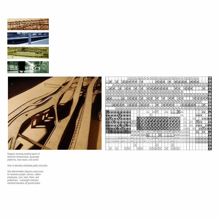
Diagram showing existing layers of electrical infrastructure, passengerplatforms, train tracks, and tunnel.
View of elevated undulating paths and pods.
Site determination diagram using iconsfor business people, tourists, stationemployees, cars, taxis, trains, andpedestrians. Lineweight indicatessectional elevation off ground plane.

View of proposed park over parking garage, overallsite with shadows displaying the undulating natureof the paths, close-up of cafe pod, view from bridge

Rental Counter
Bicycle Storage
Cafe

form/informe TERM 1_FALL 2006CRITIC: MARK GAGE
This project investigated a continuum between form and informe. It lookedat formal/geometrical scaffolding and excessive operations on thatscaffold.
The project begins with six very common shoe profiles nested to maximumefficiency within a 7’x40’ rectangle through the use of a computer program.The negative space between the shoes then becomes the positive space ofthe wall and armature to hold the shoes. As shoes are removed thetransparency of the wall changes and positive nature of the “negative” spacebetween is revealed. The shape of the shoe dictates the shape of the wallbut the wall also takes on a new layer of shape as it responds to otherconditions of efficiency, minimalism, and display. This new shape caneffectively shed traces of the generating shoe form.

Maximum number of shoe profiles nested within a7’x40’ area.
Lines drawn between every two shoes to ensure astem from the armature will uphold each shoe.
Negative space becomes the positive infill of thearmature and excess is removed based on thecenter-lines of the “columns,” leaving ameandering pattern based on the forms of theshoes, yet also independent of them.

One shoe “column” with nested shoes
Wall at maximum capacity showing ability to display the side view of as
many shoes as possible and the opaquenature and seeming disappearance of
armature when full.
Dynamic nature of wall as shoes areremoved.
Wall with very few shoes, armatureemmerges as something in itself.
Sections through wall displayingchanging positions of armature.


PLAYS TERM 1_FALL 2006CRITIC: MARK GAGE
This project called for the design of an urban club for the training,socializing, accommodation and adoption of animals. Each student was dealta different set of constraints, opportunities, and precedents.
Using the precedents of Le Fresnoy and the De Young museum as adeparture point and taking into account the urban nature of the site anddesire for light, the project integrated separate programmatic entitiesunder a common roof with possibilities for light to penetrate - both throughpunctures and skin apertures. All program is elevated off of the groundplane to liberate it for use as an outdoor dog run. Program volumes shift within their structure for other considerations such as surveillance to the dog run below. The punctures taper or expand as they pass through thefloor plates to allow light to pass to the ground.

Series of process models exploring an elevated volume and liberated ground
plane with different possiblities for light to penetrate.
Initial diagram showing a ground liftedup with volumes caught up in a structure.
Final model: elevated enclosed pods ofprogram with light shafts and dog run
at base.


Light, surveillance, and shifting volume focus.
Plans displaying division by program: sleep on top for quietand detachment, work on lower level for greater public accessand ability for surveillance, and play on ground plane for a more natural space and juxtaposition with urban context.

COHABIT TERM 2_SPRING 2007CRITIC: ALAN ORGANSCHI
This project called for the design of a 16’x16’x16’ elevated cube of space in which two characters would be required to cohabit.
Chosen characters for the project were an older male bibliophile thatrequires low-contrast lighting and a middle-aged female yoga instructorfocused on a healthy lifestyle. Because of their lifestyles, it was clear thatthe yogi could and would engage a more strenuous mode of verticalcirculation than the bibliophile, but also require a horizontal plane to do heryoga. The bibliophile would need an easy form of vertical circulation, butmore of a focus on vertical usable space to store his books. To filter lightand create a dynamic shared space, spines that function as aramature forplant growth and books as well as a climbing surface for the verticalcirculation of the yogi rise out of the ground and open up onto the roof.
Plants function as visual screenand light filter. Opaque and modular
ordinary tasks to side
Books function asvisual screen andlight filter
Ordi
nary
Spec
ial I
nter
est
Ligh
t/Pla
nts
of ‘g
roun
d’
Spec
ial I
nter
est
Ordi
nary
Degrees of interaction between the two
Yogi
Bibl
ioph
ile
Fluid movement and organization Orthogonal movement and organization
Horizontal area most important Vertical area most important

Kitchen
Bed
Bathroom
Kitchen
Study
Bathroom
Yoga
Diagram showing how lifestyle needs were translatedformally to accomodate both characters by amplifyingtheir interests and considering their physicalconditions, as well as how program placementallows for interactions, both visually and physically.
Front view, axon view, and study model.
Model displaying the implied continuation whenplaced with other structures, the program, and theeffects of the plant walls that contain herbs andvegetables for the yogi, and filter light for the bibliophile

monsterTERM 2_SPRING 2007CRITIC: ALAN ORGANSCHI
This group project (also entitled “Transmogrification”) called for areconfiguation of a typical house in New Haven using a couplingmechanism from a precedent, in this case the Ginzburg Narkomfinapartment building.
This project reexamines programmatic relationships in order to give moreequal living spaces for two units within one envelope. To accomplish itthe house is split, back portion pulled over to create individual yard zonesand equal street frontage. Cladding is ripped apart to correlate withinterior rearrangement. Car entrys question the notion of the traditional front-door entry and its availability to only one family.
In collaboration with Rebecca Beyer, Phillip Drew, Travis Eby, Isaiah King, Eric Krancevic, Janwon Lee, Tal Schori, Julie VonZumbusch, and Emily Wells
Typical
Family Territories
Yard & Sun Optimization
Material Layering
SITE CONDITIONSside yard setback
side yard setback rear yard setbackfront yard setback
SITE STRATEGY
1
2
3
4
Typical New Haven house with back garage.
House and stairs stretch to accomodate insertedgarage, forming a central landing.
Garage inserted into house, creating shared core.
House splits and shifts, isolating backyard andincreasing southern exposure.Garage rotates as geometries change.
Original house pieces contract to swallow upgarage and further enclose spaces.

First Floor Plan
Second Floor Plan

PROTOTYPEThis project called for the design of a housing unit with a dwelling unit for a single inhabitant combined with one for a household of three, positing an architectural mechanism for joining and separating the two. The project was then implemented across a site five times as part of a multi-unit project.
The project first took a simple courtyard house form, then interfered withit through a series of operations with another secondary volume. Theresultant was a switching of ownership of different outdoor spacesbased on subtle formal relationships and bounding conditions. Whenproliferated on the site the forms and sectional shifts allowed for multipleconfigurations and interlocks, creating relationships between spaces that doesn’t exist in another configuration. Outdoor space and indoor spacefor private use always exists above or below grade while paths are created for public circulation through and around the units at grade.
TERM 2_SPRING 2007CRITIC: ALAN ORGANSCHI

Diagram of sequence of initial formal volumetricchanges, showing the primary courtyard unitbeing interfered by the secondary unit by pushingupwards, skewing, and breaking as the firstvolume comes beneath it and overcomes the courtyard space. A new outdoor space for the primary unit is created on the roof of the secondary unit.
Views of an aggregation of the units on the site indifferent configurations.
Section cut displaying the three different levels.
Site plan highlighting paths through and publicoutdoor space for complex.
Initial prototype model.


Plans and sections
Wall quality showing a gradienttowards the courtyards as an indication of theiralternate presence.
Details of wall
Exploded diagram of programmatic qualities andtheir formal and sectional relationships.

individualThis project was an individual try at the Building Project program andsiting. There was to be consideration for accessibility and the couplingof a family unit and a renter unit.
The project explored unconvential uses for convential moments andmaterials in a typical New Haven home. It utilized formal relationshipsthat arose to create create suitable spaces for new required program.For accessibility purposes the house is “sunken” a half level into theground and car ramps placed on either side to provide easy access forboth renter and owner. Separate outdoor space is alotted for bothsets of occupants.
TERM 2_SPRING 2007CRITIC: ALAN ORGANSCHIBP
Site Plan
Longitudinal Section

PITCHED ROOF
Morphed and angledto create sun scoop.
FRONT PORCH
Accomodated onsecond level, only slightly offset from vertical position of previous stoop.
BAY WINDOW
Doubles as a covering for car below.
CLAPBOARD
Extends to act as a screenand become porch enclosure,giving illusion of fully-extended house.
TWO STORY
Previous bi-level facadewith pitched roof and porchfacade maintained from front,less exposed surface area.
+1/2 floor family unit
-1/2 floor renter unit

This project called for the design of a house in New Haven for a family ofthree (portion required to be accessible) and a separate renter.
The project turns programmatic restrictions into design opportunities. Theefficiency of the plan grows from the need for a clear distinction betweenowner and tenant spaces, both public and private. The house draws theoccupants in from the street onto a shared deck. The owner’s spaces arearranged around a central spine, giving visual and physical access to bothfront and back while making the outdoor spaces a significant part of theexperience inside. The tenant apartment is designed in section, creating adrammatic connection between the living and kitchen space on the groundfloor and the bedroom and study on the second level.
buildingTERM 2_SPRING 2007CRITIC: PETER DE BRETTVILLE,AMY LELYVELD, ALAN ORGANSCHI,JOEB MOORE, HILARY SAMPLEproject
TEAM B. In collaboration with Leslie Goedken, Isaiah King, Eric Krancevic, Nina Liu, Mieko Okamoto, Karen Rizvi, Matthew Roman, Zakery Snider, and Meghan Spigle
Framing Model

West Elevation
South Elevation
East Elevation
North Elevation

Section A
Section C
Section B

First Floor Plan Second Floor Plan


View through central spine
View from Kossuth Street
Renter’s living space
View of large model from above
Front view of model
Small model in site
Large model without roof

kahn TERM 3_FALL 2007CRITIC: MARTIN FINIO
This project was an analysis of the British Art Center in New Haven by LouisKahn.
The project focused on the ability of the building to provide so many different types of experiences despite (or because of the contrast with) itsmodularity. The moments when Kahn breaks out of the grid, either in sectionor in plan, and through means of eliminating physical boundaries or simplychanging material, allow for vast changes in the compression andexpansion of spaces. The views across and through spaces changedrastically from level to level, despite the seemingly similar floor plans.The project highlighted the subtle ways in which spatial recognitions canbe made apparent.
analysisIn collaboration with Marianna Mello, Lauren Mishkind, and Shane Neufeld Sectional model showing carved out interior space.
Includes panels with views that change drasticallywith only a few steps, displaying the compression andexpansion qualities.
Detail model exemplifying the trait of glimpses to otherprogram areas while still maintaining the grid. Thisentrance column detail allows a slight view to the entryarea through the rare integration of a curved surface.
Diagrams breaking down spaces and the operation ofthem to bring out relationships.
Sectional diagrams showing carved space.
Sight line diagrams showing the changing views and greater recognition of the space as one ascends tothe higher levels.

SPATIAL + CONFIGURATION
Rooms/Galleries
Interior Voids
Volumes + Structure
Envelope + Daylighting
PERFORMANCE + OPERATION
Semi-Private + Administration
Public Gallery Space
Circulation + Service
Profile of sectional interior space with windows blackened
Upward Expansion
Freedom of Space
First Floor Second Floor Third Floor Fourth Floor

kuntshalle TERM 3_FALL 2007CRITIC: MARTIN FINIO
This project called for the design of a Kunsthalle for the city of New Haven dedi-cated exclusively to contemporary art. The program also included educational facilities and other multipurpose facilities.
The aim of this project was to be both an extension of a path and a destination. The imposed path is first a connection with Chapel Street that extends and then takes with it the idea of viewing different programs along the way with the op-portunity to engage in them being sometimes direct, and sometimes only visual. It is then concentrated into a continuous circuit on the site that enters on second level, circulates down to the first, then one below grade, where it exits onto York. The ground raises to meet and become the building and then the building raises back up over the ground in its circuit, then down below it, yet always as a continuation of it as well.

Site Analyses. Investigates the program and character of surrounding spaces in order to help determine the orientation of the building and adjacencies of program in the approach to the site. The study revealedthat Chapel Street functions as a sort of arts corridor at this point, and that re-orientation of the site entrance towards Chapel could be optimal and read as an extension of the fabric of the existing character along the street.
Diagram showing the continuation of the path between the Yale RepertoryTheater and the Britsh Art Center to become the building, an interest bornin the frequent occurances along Chapel street where changes in program occur along a path and recognition of this is accomplished through a sectional shift or various bounding conditions (ex: sunken courtyard at BAC or void space at the opposite corner). Diagram also shows thedifferent qualities of the three levels of galleries.
Series of process models displaying progression and changing qualities ofinterior outdoor space to optimize public’s engagement.
Diagram of courtyard conditions and through-block paths around campus,exemplifying the quality of a courtyard to function as both a destination and a path. Red indicates public, blue indicates private or temporal.
Final model showing path and angled ground plane.

2nd Floor Plan
SECTION A

Program diagram
Plans, showing compression and expansion of galleryspace, divisions of public and private spaces, andsectional relationships to other levels.
Sections displaying use of spaces and interrelationshipsthrough visual recognition.
View looking west
1st Floor Plan
SECTION B

-1 Floor Plan
2 Floor
-1 Floor
1 Floor

Exploded plan diagrams showing gallery and viewing spaces in blue, displaying the changing nature of each floor plan. Red arrows indicate visual access outside physical constraints, withother portions of the program being on display and gray arrows indicate gallery spacewhere physical boundaries dictate the end of sight lines. At times the subject is given glimpses of the path to come later on in the circuit, another re-orientation in relation to other spaces. Changes in program are denoted by sectional shifts, harsher angles along the path, and differing bounding conditions, while still leaving the program conversion somewhat ambiguous as the continuation of the path remains intact. Gallery spaces maintain the path, yet allow for variation and differentiation through changes in the ground plane, shape and directionality, and compression and expansion in section and in plan.
- 1 Plan, Chapel Elevation
View of York Street
Chapel Street Elevation

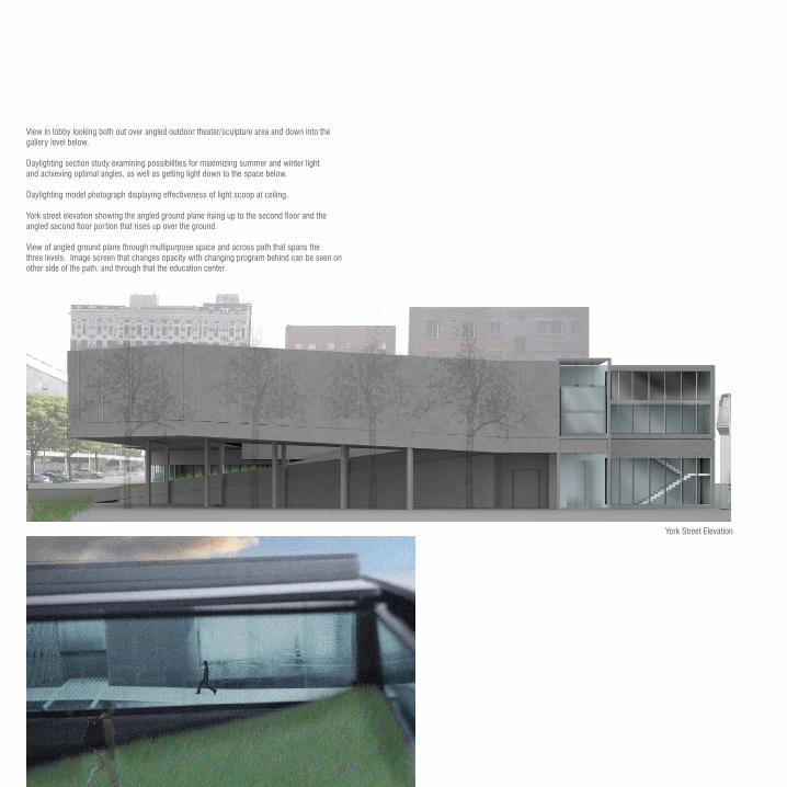
View in lobby looking both out over angled outdoor theater/sculpture area and down into thegallery level below.
Daylighting section study examining possibilities for maximizing summer and winter lightand achieving optimal angles, as well as getting light down to the space below.
Daylighting model photograph displaying effectiveness of light scoop at ceiling.
York street elevation showing the angled ground plane rising up to the second floor and theangled second floor portion that rises up over the ground.
View of angled ground plane through multipurpose space and across path that spans thethree levels. Image screen that changes opacity with changing program behind can be seen onother side of the path, and through that the education center.
York Street Elevation


View down path spanning three-level atrium.
View from York Street looking up at angled ground plane, across into gallery space on first floor, and down into gallery space on level below grade.
View from lobby area down to first floor gallery and up to outdoor theater/park aswell as across atrium area.
View from first floor gallery looking across open below grade gallery and out into sunkensculpture area on York Street. Effects of the sloping plane overhead are seen in theceiling plane.
View towards loading dock and across first floor gallery into atrium path space.
Aerial veiw of proposal in site.

urbanism TERM 4_SPRING 2008CRITIC: ANDREA KAHN
The Gowanus Canal , once a important industrial link in Brooklyn, has evolved into a barrier. The steady decline in its industrial use has opened up possibilities for rethinking its use. The project suggests a gradual phasing of a master plan in which the goal is to physically transform the canal into a usable and activated park space. Pedestrian links are created between neighborhoods and new institutional, commercial, and New Industry (based on science and technology) developments are introduced. The relationships between the different typologies are explored in the ways they relate to each other and to the gradually remediat-ing canal, and much of the program, such as the institution to study and aid in the canal’s remediation, responds to the physical needs of the site.
In collaboration with Marianna Mello
Existing Urban Forces
Existing Physical Site Conditions (flood zone and brownfields)

Programmatic Relationship Rules
Spatial Requirements Chart
Typologies
Programmatic Relationships Chart, exploring the physical ways in which
elements best relate to eachother and the possibilities for deployment on the site.
Sectional Studies

Industry
Residential
Commercial
Existing Scattered Zoning Diagrammatic Proposed Concentrated Zoning
Residential connection to west side of canal through bridge of New Industry

Zoning Strategy: The existing character of streets and neighborhoods is investigated and new zoning responds to the residential character on the west site of the canal by continuing this, gradually phasing old industry on the east bank to New Industry, introducing an institutional element, and keeping the strong commercial character of further east.
Topographic Strategy: much of the rainwater is absorbed through green, permeable ground near the edge of canal planted with species that aid in remdediation and prevent erosion. The rest drains into constructed basins that help prevent flooding.
Section through drainage basin and phytoremediation
Low-land planting:CattailsPrevent erosion
Intermediate planting:BulrushTolerates inundation
Dryland planting:SnowberryStabilizes slopes

Process models
Site Plan: Metrics, displaying the comparative structural grid and division scale for different typlologies.
View from Union Street looking South to Carroll Street
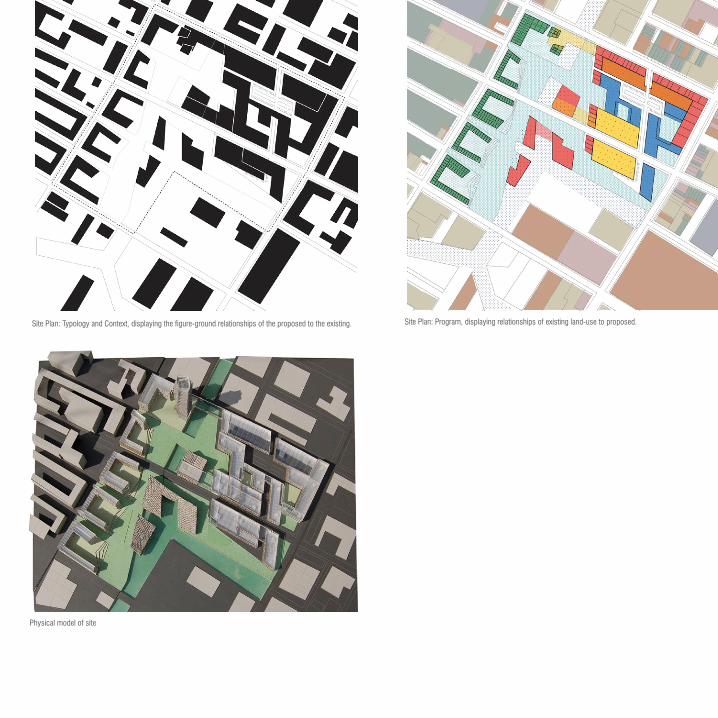
Site Plan: Typology and Context, displaying the figure-ground relationships of the proposed to the existing. Site Plan: Program, displaying relationships of existing land-use to proposed.
Physical model of site

Industrial phasing over time
Park space phasing over time
Commercial phasing over time

View of park space looking North towards residential towers

ADAPTIVE PATTERNSTERM 5_FALL 2008CRITICS: DIANA BALMORI& JOEL SANDERS
The project utilizes the equal distribution of solid and void existent in the pattern of the jali screen, deploys it at a new scale that allows landscape and building to have a permeable relationship, and allows the program, site, and ecologi-cal issues to influence and manipulate this relentless pattern into a responsive interface of landscape and architecture, inside and outside, public and private. The differentiation occurs through a figure-ground reversal, strategic voids for sun and wind, a geometric and spatial pattern analysis, and a program analysis (focusing on a comparative study of office and retail space). It draws on the precedent of the traditional Mughal gardens of India and attempts to render a new, inhabitable and highly responsive architectural solution of gradient conditions.
In collaboration with Yijun Qian
Precedents: Mughal garden and Jali screen
Ecological principles of screen maintained when flipped to be used in plan
Optimal orientation for deployment on the site determined by exposure to sun and wind

Transition to figure-ground reversal on site and assigment of program spaces accordingly.
First-floor schematic figure-ground diagram.

A coupling of the octagons is employed to create manageable spaces and relationships between portions of the site. Program is arranged based on typological needs: Retail is near entrance, primarily one-story and accessible with a shared green space. Office space is more private and higher-rise. The ground floor plan is cut away to allow for access at key points to interior courtyards and central spine of ciculation.
Emmerging geometries within pattern of screen and possibilites for coupling
and overlap.
Overlap of two nodes.
Pairing across the site and maintained central circulation route.
Public circulation spaces across site.

Programmatic Diagram
Ground Floor Plan Aerial Site Plan

GARDEN/RETAIL COUPLING
OFFICE/OFFICE COUPLING
Market report on recent developments in two typologies along with square footages.
Two different forms of coupling: sloped gradient for retail, stacked interlock for office. Analysis of typology needs: circulation and easy access for retail, degrees of privacy and square footage requirements for office.

Circulation and access points for both typologies. Physical models of each coupling instance.

GARDEN/RETAIL COUPLING
OFFICE/OFFICE COUPLING
View looking Northwest from garden space to retail space
View across retail and central space to office spaces

View across retail and central space to office spaces

OFFICE/OFFICE SECTION
GARDEN/RETAIL SECTION


View from North of site, looking South across office and then retail space.
Process models of possibilities for differentiation.

PUBLIC SQUARE PATHS OCCUPIABLE GREEN
Gradient of paved to plantings.
CIRCULATION DEFINING
SPACE DEFINING
Tree plantings
Conceptual Physical Site Model

Field stationTERM 6_SPRING 2009CRITIC: JOHN PATKAUwith TIM NEWTON
This project called for a field station on Horse Island, a protected island owned by Yale University for research purposes and part of the Thimble Island chain a few miles off the Connecticut shoreline. With the project I chose to focus on the idea of habitat on the island. The design provides a constructed habitat for con-ditions that already exist on the island (tidepools, bird nesting areas, etc.), but is concentrated in a specific area for new research. Physical access to the rest of the island is limited to only the program pieces that require it. A system of walls and strategic patterning acts as a vehicle for the habitat and responds to the requirements for inhabitation, but also to structure. The walls serve as a frame-work for enclosed program volumes and the apertures within them are spaced in such a way so as to support the primary structure of the volumes. A modular prefabricated concrete system is employed for the production of the walls.
Layers of striation and different habitats present on the island due to tidal cycle.
Varying transparencies present in the dense tree cover of the island.
Large cracks and crevaces in boulders on the island.
Tidal pool on island and sea creatures within. Sectional study of striations through island and concept of layers of habitat.
Process model exploring structural and
habitat possibilites of patterning

Process model focusing on enclosure and support possibilites of wallls
Diagramatic process model de-lineating the different elements through color
Explorative site analysis model showing the eb and flow of the tides and deposi-tories created by tide pools.
Explorative site analysis model showing negative spaces, through the changing tree canopy densities and cracks in boulders around the perimeter of the site.

Successive drawings show sequence of build-up:Site is selected based on location as the lowest-lying point on the island, and thus conducive to tide pools. A series of guide lines, drawn tangentally to the topography are imposed and the footprint for the walls are derived from these lines. Sectional shifts are created between these lines, including the
constructed tidepool area and a raised outdoor space. Enclosed program placement is based on the idea that visitors coming for a meeting experience the length of the site along a procession to the main meeting
space without having physical access to areas of the site that may be disturbed by them. “Educational” occupants have a network of connective spaces above the flood line and access to the rest of the site for
research purposes.
Particular habitat exsitant only at perimeter and required disturbance area to access it from existing building. Proposed: concetration of habitat and building into layers within a particular area that allows for less disturbance across entire site.
LAB

Midterm model
CLASSROOMS
LAB
COLLECTION
MEETING HALL

View showing perforated wall and varying shapes and uses within it, as well as transparent quality that is an abstraction fo the tree canopy.
Plan
Diagrams of habitat possibilites and building function possibilities (respectively) of wall perforations.

Production and assembly diagram of pre-cast concrete panels. Reinforcing bars are placed within a frame and 5 pans are arranged differently within this frame for variation. This modular system allows for variation in the surface of the wall with the efficiency of having only a few mold pans. The concrete is poured into the frame and rebar on the outside of the frame is used to slot into an adjoining panel and connect. Vertical spines of structure help carry the loads on the walls.

View of site looking Northeast
Longitudinal site section through meeting hall and constructed tidepool area.

View of collection space and paths supported by extended beams.
Lab space and supporting truss structure.
Meeting hall overlooking cove and exit to outdoor meeting space through increased perforations.

Sections through two conditions showing support language.
View along tide pool area to meeting space.

View to cove from meeting space.
View to back of classrooms.
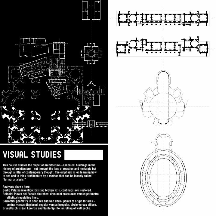
visual studies FORMAL ANALYSIS WITHPETER EISENMAN
This course studies the object of architecture—canonical buildings in the history of architecture—not through the lens of reaction and nostalgia but through a filter of contemporary thought. The emphasis is on learning how to see and to think architecture by a method that can be loosely called “formal analysis.”
Analyses shown here:Serlio Palazzo invention: Existing broken axis, continuos axis restored.Rainaldi Piazza del Popolo churches: dominant cross axes versus perimetral elliptical regulating lines.Borromini geometry in Sant’ Ivo and San Carlo: points of origin for arcs - central versus displaced, regular versus irregular, circle versus ellipse.Brunelleschi’s San Lorenzo and Santo Spirito: unrolling of wall poche.


drawing&geometry JOHN BLOOD KENT BLOOMER
This course investigates drawing as a means of architectural communication and as an instrument of individual inquiry. Principles of two- and three-dimensional geometry are extensively studied and analyzed.
Shown:Weaving of concentric pill shapes and proliferation of it with regulating lines.Investigation of lineweight on perception of foreground and background in platonic forms with three-point perspective.Construction drawing of “widget” displaying embedded shapes.Tiling project overlay of diamond and circle patterns with resulting relationships highlighted through lineweight and selective exclusion.Handed study, pairing individual objects with a certain rule, and then columns of individuals to result in varying negative spaces.


CRAFT, MATERIALS, COMPUTER-AIDED ARTISTRY
KEVIN ROTHEROE
Two projects were completed in this course: one an architectural screen utilizing the process of aluminum extrusion in an unconventional way and another a series of plaster panels with two colliding optical effects. The screen overcame the monotony often present in alumnimun extruded pieces through utilizing asymmetry and the possibility for different depths and different forms of interlock to create a variation with only a single extrusion die. The plaster panels created a second and third continual pattern in their tiling, dissolving the mundane rectangular shape of the panel and creating extremely varied views of the piece on a whole from different directions.

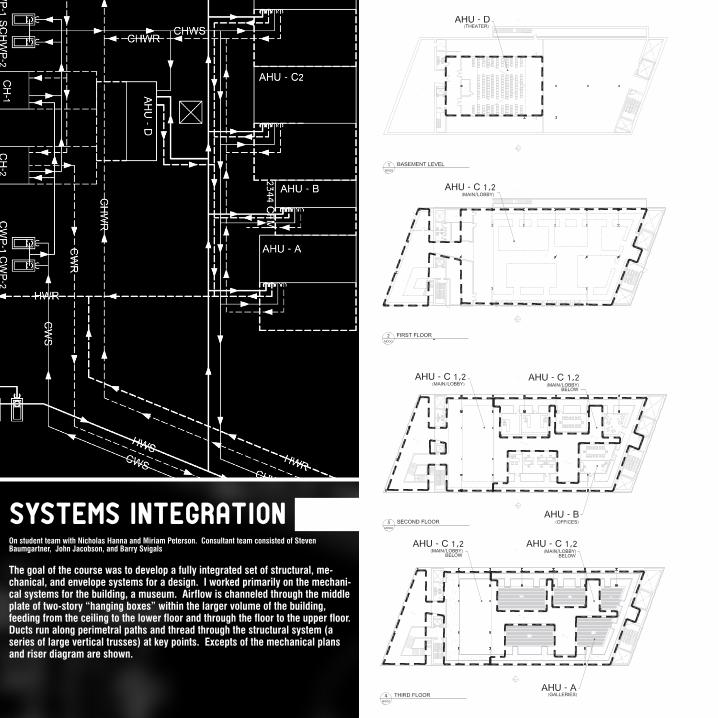
systems integration MARTINFINIO
The goal of the course was to develop a fully integrated set of structural, me-chanical, and envelope systems for a design. I worked primarily on the mechani-cal systems for the building, a museum. Airflow is channeled through the middle plate of two-story “hanging boxes” within the larger volume of the building, feeding from the ceiling to the lower floor and through the floor to the upper floor. Ducts run along perimetral paths and thread through the structural system (a series of large vertical trusses) at key points. Excepts of the mechanical plans and riser diagram are shown.
On student team with Nicholas Hanna and Miriam Peterson. Consultant team consisted of Steven Baumgartner, John Jacobson, and Barry Svigals


This four-week summer workshop took place in Rome and was designed to provide a broad overview of the city’s major architectural sites, topography, and systems of urban organization, with drawing as the primary tool of discovery.
Projects were undertaken that explored the media of watercolor, pen, and pencil.
A final project investigated the church of Sant’Ivo and the perceptual creation of its own internal axis. Through drawing, the way in which the interior courtyard detaches itself from external relationships and creates a new axis is investigated.
Rome seminar ALEC PURVESSTEVEN HARBY
Piazza del Popolo
Tempietto
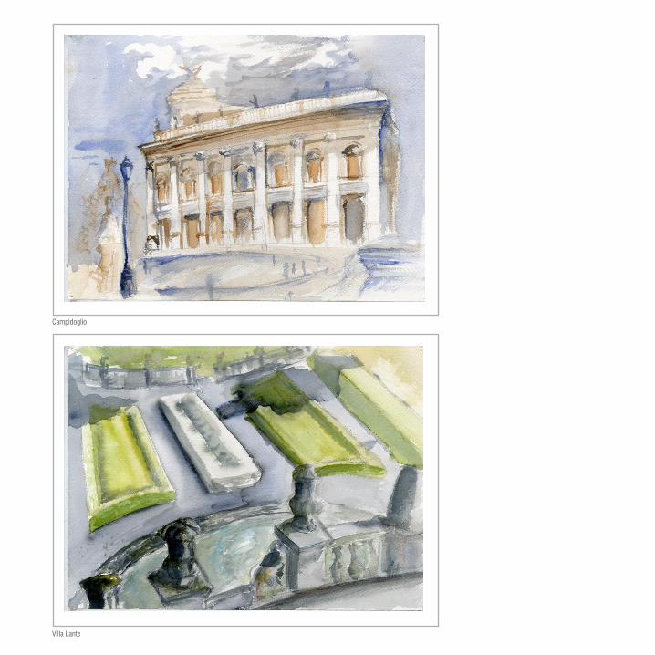
Campidoglio
Villa Lante

TempiettoGardens at Villa Farnese
Alley in Rome

Gardens of Ninfa
Gardens at Villa Farnese

Knights of Malta
Sant’IvoBernini sculpture

Sant’Ivo
Santo Costanza Pantheon

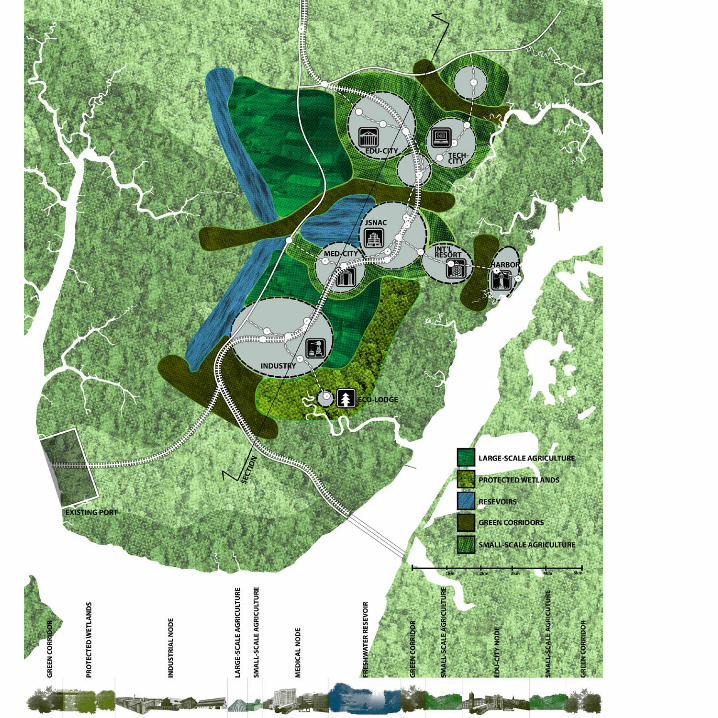
Sustainable design JOINT FORESTRYNAOMI DARLING
This seminar looks broadly at sustainable architectural design, reviewing environmental issues, key documents, and larger-scale strategies and, then narrowly, at the current and emerging detailed methods used to support design development of sustainable buildings, communities, and cities. In the course we were asked to design a masterplan for a sustainable city and then develop a specific portion as a designed ecological experiment. The masterplan worked with an idea of small-scale, walkable city nodes connected by mass transit and surrounded by small-scale agriculture and protected wetlands. The ecological experiment expounded on the idea of mass transit connections and investi-gated different options for wildlife corridors and their impacts on human and animal and plant life over time.
Group projects, designed within a team, all shown documents entirely produced by myself. Design team: Stephanie Carlisle, Tom Gibbons, Kyle Williams, and Seth Zeren.
Treatment 1 (bridge)
Treatment 2 (underpass)
Control (traditional road)

furniture design PETER DE BRETTEVILLE
The project was based upon an idea about efficiency - both with regard to mate-rial use and with regard to time from first to last moment of production. The CNC mill was the vehicle for quick production and all connections and surface effects were worked into a single mill file. The seat and back of the chair come directly from the interior pieces of the arm/leg circuits. With the efficient use of material and precision of the mill, three chairs may be cut from two sheets of 4’x8’ ply-wood. Connections are notched so that, after one hour on the mill, a mallet and twenty minutes are all that is needed for assembly. The surface effect expounds on the precision of the mill, incrementally stepping away the plywood layers to reveal different colors and contrast.

Mill file on a 4’x8’ sheet of plywood, showing material for one and a half chairs
