krell playback systems - krell industries, incorporated, america's
TRANSCRIPT

~g and Digital Products
KRELL PLAYBACK SYSTEMS
KPS-20t Transport
KPS-20i Integrated Transport & Processor
KPS-20i//Integrated Transport, Processor & Digital Preamplifier
OWNER’S REFERENCE

TABLE OF CONTENTS
2
4
5
6
7
8
13
15
16
16
18
19
22
24
25
26
27
28
INTRODUCTION
UNPACKING AND PLACEMENT
GENERAL DESCRIPTION OF KPS-20 SERIES OWNER’S REFERENCEAC POWER GUIDELINES
KPS-20 SERIES FRONT AND REAR VIEW
KPS-20 BASIC OPERATION
COMPLETE TRANSPORT FEATURES AND FUNCTIONS
KPS-20i AND KPS-201//DETAILS
KPS-20i//VOLUME CONTROL
KPS-20t DETAILS
TRANSPORT TO PROCESSOR INTERLINK CONSIDERATIONS
TIME SYNC
REMOTE CONTROL
QUESTIONS AND ANSWERS
KPS-20i TYPICAL SYSTEM SETUP
KPS-20i//TYPICAL SYSTEM SETUP
KPS-20t TYPICAL SYSTEM SETUP
SPECIFICATIONS ’~ ~
WARRANTY AND SERVICE

INTRODUCTION
Thank you for your purchase of the KRELL PLAYBACK SYSTEM-20 seriescomponent. Influenced by KRELL Reference and Audio Standard Seriescomponets, the KRELL PLAYBACK SYSTEM-20’s incorporate the latestdevelopments in Krell technology. Their advanced digital reconstructionsystem, input and output connection capabilities, ergonomics, and stunningaesthetics make the KRELL PLAYBACK SYSTEM-20 series an impressivestatement of audio technology.
KRELL PLAYBACK SYSTEM-20 (KPS-20) series components utilize a top loaddesign based on a high performance Philips transport mechanism. Thetransport is housed in a solid machined block of brass and independentlysuspended from the chassis by low-stored-energy isolation mounts. The mainchassis provides the first line of shock energy isolation with its own series oflow-stored-energy suspension mounts, leaving the inertially massive brasslaser chassis to dissipate any residual energy before it can influence thetracking of the laser. Krell-written micro-code controls all transport functionsand input selections through a custom user interface. This interface is writtenwith performance and user flexibility as key design goals. Disc stabilization isaccomplished with a custom five point magnetic clamp and proprietary hubalignment. The heavy motorized cover assembly isolates the compact disc fromambient light. During playback the underside of the CD is bathed in greenlight. This particular light spectrum increases the signal-to-noise of the laser’sphoto-diode which, in turn, increases its reading accuracy.
The KRELL PLAYBACK SYSTEM-20t comes standard with all current digitaloutput formats: ST fiber optic, AES/EBU balanced, SPDIF coaxial, EIAJ opticaland KRELL Time Sync.
In the KPS-20i and KPS-20i/I the identical transport mechanism is coupled toan upgradeable software based processor. Data is transferred through customfilter algorithms performing KRELL written reconstructive software at a 16Xoversampling rate through a Motorola DSP-56002 processor running at 66 MHz.The 24 bit data is then fed to four differentially configured Burr Brown 20-bitColinear DAC’s.
2

All critical circuitry utilizes four layer glass epoxy circuit boards. With its 100 VApower supply and 11 independent stages of regulation, the power supply of theKRELL PLAYBACK SYSTEM-20 is a rock solid source of pure current andvoltage for the digital and Class A analog output stages. The output stage isclassic KRELL. All output circuits are DC coupled, Class A and complementary.The output stage has 18 volt rails and fully differential balanced outputs on goldplated, berrylium copper XLR connectors. Single-ended outputs are alsoprovided via custom gold plated RCA connectors.
In the KRELL PLAYBACK SYSTEM-20i/I the high level output stage of theKPS-20i is replaced with a line level output stage and volume control simfliar tothat of the KRELL KRC-2 preamplifier. This stage is optimized to drive the inputof a power amplifier directly.
The KPS-20i and KPS-20i/I support all major digital input formats: one ST fiberoptic, one AES/EBU balanced, two SPDIF coaxial, and one EIAJ optical. Theycome standard with an SPDIF coaxial digital output. ST, EIAJ, and KRELL TimeSync outputs are available as an option. All input switching is accessible from thefront panel or the remote control. KRELL’s proprietary Data Recovery and JitterRejection Module recovers all data from external sources, reducing jitter toexceptionally low levels.
This Owner’s Reference is intended to guide the clear, trouble free installationand operation of your KRELL PLAYBACK SYSTEM-20. Should you have anyquestions or comments, please feel free to contact your authorized dealer or theKRELL staff for assistance.
In the unlikely event that your KRELL PLAYBACK SYSTEM-20 should requireservice, you will be pleased to know that it is backed by a comprehensiveCustomer Satisfaction policy and one of the most advanced service facilities inthe industry. For detailed information on the terms and conditions of service,please consult the Warranty and Service section of this Reference, WarrantyRegistration Card, or an authorized KRELL Dealer/Distributor.
3

UNPACKING AND PLACEMENT
1. Once the box is opened and top layer of foam removed, the following itemswill be visible:
1 KPS-20
1 KPS-20 Remote Control
1 KPS-20 Custom 5 point CD clamp (packed beneath the KPS-20)
1 AC power cord
1 T-10 torx driver1 Packet containing the Owner’s Reference and Warranty
Registration Card
NOTE: If any of these items are not included, please contact your authorizeddealer immediately for assistance.
2. Carefully remove the unit and accessories from the box. Remove theprotective plastic wrap from the unit.
NOTE: Save all packing materials. If you must ship your KPS-20 in the future,repack the unit in its original packaging to prevent transit damage. KRELL is notresponsible for damage incurred during the shipment of goods without factoryapproved packing material.
PLACEMENT
Before you install the KRELL PLAYBACK SYSTEM-20 into your system, werecommend that you follow these guidelines in choosing the location. This willfacilitate a clean, trouble-free installation. The KPS-20 does not require any typeof special rack or cabinet for installation. Dimensions are described on page 27.
1. Place the unit on a firm level surface away from excessive heat, humidity ormoisture. Make sure there is enough room at the top for a compact disc tobe placed within the chassis. Approximately ten inches is necessary.
2. Although well shielded, the KPS-20 should not be place~d in close proximityto hum-sensitive components such as preamp phono stages or turntables.The power supply may create interference and induce hum.
3. The KPS-20 incorporates an advanced suspension system and does notrequire additional mass coupling or isolation. You may experiment with feet orcones as long as they don’t permanently affix to the chassis. Any unauthorizedmodifications to the electronics or chassis will void the warranty.
4

GENERAL DESCRIPTION OF KPS-20 SERIF_~ OWNER’S REFERENCE
The features, functions and operation of the transport are identical for allthree KPS-20 Series products. Descriptions of them are divided into twosections: Basic Operation provides a quick installation procedure; CompleteTransport Features and Functions provides details on all KPS-20 transportcapabilities. Features specific to the KPS-20i, KPS-20i// and KPS-20t aredescribed on pages 13, 15 and 16 respectively.
As with all sophisticated products, a complete reading of this Owner’sReference will provide thorough understanding of the KPS-20 Series products.Please contact your authorized dealer, distributor or the factory if you have anyquestions not addressed by this Reference.
IMPORTANT NOTE: The use of CD rings, mats, or other devices attached toindividual CDs is not recommended. To be completely effective, the KPS-20 clampmust make direct contact with the CD. Otherwise, erratic playback and~or poorsound may occur
AC POWER GUIDELINES
The KPS-20 has superb regulation and does not require a dedicated ACcircuit. We strongly advise against connections through extension cords ormultiple AC adapters. High quality 15 amp grounded AC strips are acceptable.High quality AC line conditioners or filters can be utilized if they are groundedand meet or exceed the unit’s Power Supply rating of 100VA.
CAUTION: Do not remove or bypass the ground pin on the end of the AC cord.This may cause RFI (radio frequency interference) to be induced into yourplayback system.
5

KPS-20 SERIES
FaONT vii w
@ ®
KPS-20i/I
1. Transport function indicators for: Disc Management System, Program, Pause and Introduction2. Transport function indicators for: A-B loop, Repeat Disc, Repeat Track and Random Play3. Track and Index number display window4. Elapsed or remaining time display window; displays volume level on KPS-20i/I5. Transport Power on/off button6. Display control buttons7. Level control buttons for Volume up and Volume down; KPS-20i/I only8. Infrared remote control receiver window9. Sync indicator: Displays whether a digital source has linked with the processor
10. Digital Input select buttons and indicators for: Internal CD Transport, External Coax 1, ExternalCoax 2, External EIAJ Optical (Optics), External ST Optical and External AES/EBU XLR balanced
11. Emphasis indicator: Displays whether deemphasis circuitry is engaged12. Open/Close button for sliding cover13. Transport function buttons for: Disc Management System, Program, Repeat and Pause14. Transport function buttons for: Stop, Play, Track Back, Track Forward, Search Back and
Search Forward15. Transport function buttons for: Direct Number Access Keypad, Index Back and Index Forward16. Transport function buttons for: A-B loop, Random Play, Introduction and Direct Time Access
REAR VIEWI@l
17.18.19.
20.21.22.23.
24.25.26.27.
@ @ @ @Left and Right Balanced and Single-Ended Analog Outputs; not on KPS-20tEIA~J Coax Digital Output ,Digital Output Module consisting of two ST optical (one can be used for Time Sync)and one EIAJ Optical Output: Sta~daJrd on KPS-20t;, Optional for KPS-20i and KPS-20i/IRemote In and Out (for use with future switching devices)Manual or Auto Cover SwitchRemote Access Switch for use with future switching devicesDigital Inputs: EIAJ optical (Optics), Coax 1, Coax 2 or ST optical (optional), AES/EBU,ST optical; not included on KPS-20tFuse holderMain On/Off Power SwitchIEC Standard 15 amp AC power cord receptacleNot shown, KPS-20t only: AES/EBU Digital Output

KPS-20 BASIC OPERATION
Below are instructions for a quick installation of the KPS-20. Please refer tothe Typical System Setup illustrations on pages 24, 25, and 26. Also, allow theunit to settle at room temperature before operation is started.
1. Plug the KPS-20 into the standard wall AC receptacle. Connect the KPS-20output to the appropriate location: KPS-20i to preamp input; KPS-20i/I toamplifier or crossover input; KPS-20t to D/A processor input. Engage thepower switch on the rear panel by pushing it up to the ON position. Thispowers the processor sections in the KPS-20i and KPS-20i/I.
2. Press the Power button on the front panel or on the remote control to powerthe transport stages. The display section will now illuminate. The processorportion of the KPS-20i and KPS-20i/I is on at all times once the rear panelswitch is engaged. This is to insure thermal stability and improve sonicperformance.
3. Press the Open/Close button on the front panel and the top cover assemblywill open, exposing the CD transport and spindle. Place the compact disc,label side up, onto the drive spindle. Place the five point custom clamp ontothe drive spindle, securing the CD in place. Make sure the clamp is centeredfirmly on the custom CD spindle hub. Press the Open/Close button again orPlay and the cover will close.
NOTE: In the event that you wish to rapidly change a number of CDs, theKPS-20 can be played with the cover open. Move the switch on the back panelmarked "Manual~Auto" to the "Manual" position..The KPS-20 will now playwith the cover open. However, do not forget that you are compromising thequality of the music when the CD is exposed to light. Also, it is alwayspreferable to close the cover when playing music at a high volume in order tomaintain optimum tracking.
4. Press Play on the front panel or remote control. Note: if you pressed Play instep 3 the disc will already be playing. The disc will start playing from track 1.To select a ’different track you can press the track forward {> I} or track back{I <} button until you reach the desired track number or punch the number ofthe desired track into the keypad on the front panel or rem’ote control.
5. Press the Stop button to stop play.
7
COMPLETE TRANSPORT FEATURES AND FUNCTIONS
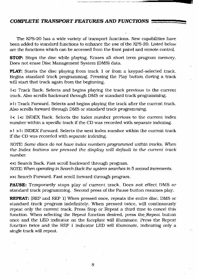
The KPS-20 has a wide variety of transport functions. New capabilities havebeen added to standard functions to enhance the use of the KPS-20, Listed beloware the functions which can be accessed from the front panel and remote control.
STOP: Stops the disc while playing. Erases all short term program memory.Does not erase Disc Management System (DMS) data.
PI~Y: Starts the disc playing from track 1 or from a keypad-selected track.Begins standard track programming. Pressing the Play button during a trackwill start that track again from the beginning.
I<: Track Back. Selects and begins playing the track previous to the currenttrack. Also scrolls backward through DMS or standard track programming.
> I : Track Forward. Selects and begins playing the track after the current track.Also scrolls forward through DMS or standard track programming.
I< I<: INDEX Back. Selects the index number previous to the current indexnumber within a specific track if the CD was recorded with separate indexing.
> I > I : INDEX Forward. Selects the next index number within the current trackif the CD was recorded with separate indexing.
NOTE: Some discs do not have index numbers programmed within tracks. Whenthe Index buttons are pressed the display will default to the current tracknumber.
<<: Search Back. Fast scroll backward through program.NOTE: When operating in Search Back the system searches in 5 second increments.
>>: Search Forward. Fast scroll forward through program.
PAUSE: Temporarily stops play of current track. Does not effect DMS orstandard track programming. Second press of the Pause button resumes play.
REPEAT: (REP and REP 1) When pressed once, repeats the entire disc, DMS standard track program indefinitely. When pressed twice, will continuouslyrepeat only the current track. Press Stop or Repeat a third time to cancel thisfunction. When selecting the Repeat function desired, press the.~Repeat buttononce and the LED indicator on the faceplate will illuminate. Press the Repeatfunction twice and the REP 1 indicator LED will illuminate, indicating only asingle track will repeat.
8

0-9 NUMBERED KEYPAD: The direct access keypad makes track selectionquick and easy. When using the direct track access function, the selectedtrack will begin play immediately after a one or two o.digit number is selected.Select the number of your choice directly or follow the program selectionsequence if writing a program..
RANDOM: Will play tracks in a non-selected order. Press the Random buttonand the disc will begin play in a sequence other than the original. Press againand another randomly selected track will play. Press Stop to exit the Randomplay mode.
INTRO: Plays a 20 second sample of each track on the disc. Press the Stopbutton to resume normal play.
DISPLAY: Toggles between the time into the current track and the amount oftotal disc time remaining.
DIM: Shuts off the display and function LEDs. Second press activates thedisplay and function LEDs.
A/B: The KPS-20 can make a loop between two pre-determined points within atrack. This is helpful when you need to repeat a specific segment of a track.
How to Create an A/B Loop:
Start play of track. When you hear the part that you want as the beginning ofthe loop press A/B to insert the start position. Press A/B again to insert finishposition. A/B play will automatically begin and continue indefinitely. PressStop or A/B again to delete the A/B program.
ACCESS: The Access function gives you the ability to numerically select aposition within a specific track program. This is valuable when exact startpositions are critical.
9

COMPLETE TRANSPORT FEATURES AND FUNCTIONS -
How to Gain Access to a Specific Time in a Track:
1. Press Access. Two zeros will show on the display.2. Enter a one or two digit track number, then press Program.3. Enter a one or two digit minute number, then press Program.4. Enter a one or two digit second number, then press Program. The track will
immediately begin play at the designated time.
EXAMPLE: Here is a program to begin play at Track 2, 1 minute and 1 1seconds into the piece.
1. Press Access2. Press 2 then Program3. Press 1 then Program4. Press 11 then Program
NOTE: When entering an access number, remember not to exceed the track’splaying time while programming. When this occurs your access number will notbe acknowledged.
PROGRAM/PROG on Remote: Standard track programming gives you theability to select which tracks you would like to hear and the order in which youwould like to hear them. This method of programming is short term and will becleared when you press the Stop button. Once a program is written, basicfunctions like Pause, Repeat, Track forward, and Track Back work within theprogram. The program will be cleared from memory once the last programmedtrack is played or the Stop button is depressed. The program will continuallyplay if the Repeat button is depressed. To temporarily stop play within aprogram, press the Pause button. Remember, Stop will erase the program.
SPECIAL NOTE: If you get confused with the sequence while in the middle ofprogramming, press the Stop button and start again. This will clear allprogramming in temporary memory.
HOW TO WRITE A PROGRAM
1. Press the Program button on the front panel or remote control. The ProgramLED will be illuminated next to the display. This puts the machine inProgram mode.
10

2. Select the track you want first in the program. You can use the TrackAdvance and Reverse buttons to select the track numbers or punch thenumber directly into the keypad.
3. After you select the track, press the Program button again. The track youselected is now in program memory.
4. Repeat this sequence for each track you want in your program.
EXAMPLE: Here is a sample program sequence
1. Press Program2. Press 2, then Program3. Press 4, then Program4. Press 6, then Program5. Press 8, then ProgramPress Play and the program sequence 2, 4, 6, 8, will begin.
NOTE: While playing the program, the Track Forward, Track Back, Repeat, andPause functions work within the program.
To clear the program memory press the STOP button.
DMSThe Disc Management System (DMS) allows a track program you have
written to be saved indefinitely in the KPS-20’s memory.
CAUTION: Please proceed slowly and follow the Sequence carefully whilelearning to program DMS. The DMS function will appear to be malfunctioning ifthe sequence is changed.
How to Write a DMS Program
1. Press the Program button on the front panel or remote control. The programLED will be illuminated next to the display. This puts the machine in theprogram mode.
2. Follow the standard program instructions as described above.
3. Once the Program is written, press the DMS button on the front panel orremote control. Press the Program button and the DMS LED on the frontpanel will illuminate. The DMS program is now complete.
11

COMPLETE TRANSPORT FEATURES AND FUNCTIONS -
EXAMPLE: Here is a sample DMS program sequence
1. Press Program2. Press 1 then press Program3. Press 3 then press Program4. Press 5 then press Program5. Press 7 then press Program6. Press DMS7. Press Program
The DMS program is now entered into the KPS-20’s permanent memory. Toplay the program, press DMS, then Play. The DMS program sequence 1, 3, 5, 7,will begin.
How to PLAY a DMS Program
1. Insert the disc into the KPS-20.
2. Close the top cover. The DMS LED will illuminate indicating there is a DMSprogrammed disc in the machine.
3. Press the DMS button on tile front panel or remote control.
4. Press Play. The Program LED on the front panel will illuminate and the DMSprogram will begin.
NOTE: If the Program LED is not illuminated, the KPS-20 has not recognized theDMS program and will play the disc in the normal way.
How to Erase a DMS Program
Once the disc is enclosed in the KPS-20 and the DMS program LED is illuminated,press the DMS button and immediately press the Stop Button. The DMS LEDwill extinguish, indicating the DMS program is erased.
12

KPS-20i AND KPS-20i/I DETAILS
This is a description of the additional features and functions common to theKPS-20i and KPS-20i/I. Please contact your KRELL dealer or the KRELL stafffor assistance if there are any questions not covered~in this Reference. Pleaserefer to the KPS-20i and KPS-20i/I Typical System Setups illustrations onpages 24 and 25.
CAUTION: When making connections to this component or any other, make surethe power amplifier is OFF and the preamplifier is in the MUTE or STANDBYmode.
ANALOG OUTPUT CONNECTIONS
The KPS-20i and KPS-20i/I are equipped with two analog outputconfigurations: Single-ended via RCA connectors and balanced via XLRconnectors. If your preamplifier has high level balanced inputs, we recommendthe balanced outputs be used. There are considerable sonic benefits to begained with use of the balanced format.
The XLR pin configuration is described below.
Pin 1 GroundPin 2 Non-inverting (0°)
Pin 3 Inverting ( 180°)
The left and right channel RCA and balanced outputs are labeled on the backpanel. Care should be taken that the correct left/right orientation ismaintained.
NOTE: These two outputs can be used to simultaneously feed different systems.
EMPHASIS LED
Emphasis is part of an encode/decode recording technique. Discs and/ortracks that were recorded with this process will cause the Emphasis LED toilluminate. When the Emphasis LED is lit the appropriate circuitry is activatedto provide fiat frequency response. ~
13

KPS-20i AND KPS-20i/1 DETAILS
DIGITAL SOURCE TO KPS-20i INTERLINK CONSIDERATIONS
Care should be taken in selecting the type of cable used to link a digitalcomponent to the KPS-20i or KPS-20i/I. Although the KPS-20 series will acceptall industry standard formats, we suggest using the ST wide bandwidth format.Refer to the KPS-20i Typical System Setup on page 24.
DIGITAL INPUT CONNECTIONS
The KPS-20i and KPS-20i/I come standard with most current digital inputformats: ST fiber optic, AES/EBU balanced, EIAJ fiber optic, and two SPDIFcoaxial inputs.
Connect the sources’ digital output(s) to one of the digital inputs on theKPS-20i or KPS-20i/I. When the corresponding input of the desired digitalsource (must be ON) is selected, the appropriate input indicator LED willilluminate. The Sync LED will then illuminate, indicating the digital source andinternal processor have linked. The Processor automatically selects the correctinput frequency for the source.
DIGITAL OUTPUTS
The KPS-20i comes standard with one coaxial digital output. Signal from theinput selected on the front panel or remote is routed to this output for sendingto a digital recording device or external D/A processor.
An optional Digital Output Module is available to provide additional outputs inST optical and EIAJ optical formats. Also included is a second ST output thatcan be internally switched between the normal digital output and Krell’sproprietary Time Sync system. Please refer to pages 16 through 18 for moreinformation about the connection of digital outputs and Time Sync.
14

KPS-20i/I VOLUME CONTROL
All input and output connections for the KPS-20i/I are identical to those forthe KPS-20i, with the exception that the KPS-20i/I analog outputs connectdirectly to the inputs of a power amplifier or crossover. Please review theKPS-20i/I Typical System Connection Diagram on page 25.
Operation of the KPS-20i/I is identical to the KPS-20i with the exception of thevolume control. The operation on the volume control and associated display aredetailed below.
VOLUME CONTROL
The KPS-20i/I utilizes a discrete ladder network volume control. When volumeUp or Down is selected via the front panel or the remote control, the numericdisplay will provide a 0--158 step indication of the volume level. The levelposition will remain on the display for a few seconds and then return to thetransport display mode.
To adjust listening level hold down either the volume Up or Down button. Thevolume will begin increasing or decreasing in one step increments. After a shorttime, the volume will begin changing in larger, multi-step increments. This isintentional and allows for more rapid changes in volume adjustment.
To check your volume level without changing the level, briefly depress eitherthe volume Up or Down button. The display will show your present volume levelfor a short time before returning to the transport display mode.
CAUTION: Do not connect the output of the KPS-20i/I to ~the input of a preamplifierThe KPS-20i/I output is designed for connection directly to the input of an amplifierand may damage a preamplifier input.
15

KPS-20t DETAILS
All operational features and functions of the KPS-20t are described on pages7 through 12 of the Reference. Detailed below are various issues related to theconnection of the digital outputs. This information is also valid for the KPS-20iand KPS-20i/I if the optional Digital Output Module is installed. Please refer tothe KPS-20t Typical System Setup on page 26 for a detailed view of how theKPS-20t is installed in an audio system.
CAUTION: When making connections to this component or any other, make surethe power amplifier is OFF and the preamplifier is in the MUTE or STANDBY mode.
DIGITAL OUTPUT CONNECTIONS
The KPS-20t comes standard with all current digital output formats:ST fiber optic, AES/EBU balanced, SPDIF coaxial, EIAJ optical and KRELLTime Sync.
Connect the digital output(s) of the KPS-20t to the input(s) of a digital recordingdevice and/or digital-to-analog processor.
The KPS-20t is also fitted with Time Sync. Time Sync is a proprietary systemthat locks the clocks of the transport and certain KRELL processors. For acomplete description of Time Sync, see page 18.
If you are using the Time Sync option, connect an ST cable between the KPS-20tTime Sync output and Time Sync input on a Krell processor.
For specific instructions on connecting ST cables refer to page 17.
TRANSPORT TO PROCESSOR INTERLINK CONSIDERATIONS
Care should be taken in selecting the type of cable used to link yourKPS-20t and processor. We suggest using the ST wide bandwidth fiber opticformat. This format has a data rate of approximately 50 megabit. This allowsaccurate transmission of the digital bit stream without data corruption andproves to be sonically superior. Using a fiber optic interconnect also reducesground loop problems often associated with quality audio systems.
If coaxial cable is used, it should be non-capacitive and have a bandwidth inexcess of 10 MHz to prevent drop-out errors. For best results with coaxial cablewe recommend the AES/EBU balanced format. The AES/EBU format is a _+ 5 voltbalanced digital transmission. Because of the high voltage balanced format, thissystem allows for accurate data transmission and has great sonic advantagesover standard single-ended coaxial or EIAJ fiber optic formats. The AES/EBUcoaxial cable must have two conductors and a shield for balanced termination.
16

HOW TO CONNECT ST CABLES
1. Remove the plastic cover from the outside of the ST transmitter (located ontransport) and receiver (located on processor).
2. Remove the plastic cap from both ends of the ST cable.
3. Locate the key tab on the end of the ST cable.
4. Locate the slot on the top of the ST receptacle.
5. Slide the cable connector into the ST receptacle, with the key guided into thedesignated slot.
6. Gently push the connector into place, depress the internal spring, and twistthe outer collar clockwise to secure the outer ring to the posts on the chassisconnector.
7. Use the same procedure for the processor input.
ST/TIME SYNC OUTPUT
The ST connector labeled ST/Time Sync can be switched between TimeSync and a normal data output. The KPS-20t comes with this output Set forTime Sync. Follow the procedure below to switch it to a data output:
1. Turn the power amplifier Off and the preamplifier to Mute or Standby
2. Turn the two thumbscrews counterclockwise until they release from thechassis
3. Hold the thumbscrews and pull the panel/board assembly straight out of theunit
4. On the circuit board there is a switch labeled Time Sync on one side, Dataon the other
5. Move the switch to the Data
6. Slide the board back into the chassis
7. Firmly press the board into its mating connector
8. Turn the thumbscrews clockwise until they are tight
17
TIME SYNC
TIME SYNC
Time Sync is an independent clock data transfer system that was developedto eliminate recovery jitter. Time Sync couples the high speed master clockoutput from the transport directly to the processor. This means there is onesystem master clock for the transport and processor. The use of the Time Syncsystem requires that a KRELL processor be equipped with a Time Sync input.It also requires that the Time Sync output of the KPS-20t be connected to theTime Sync input of the processor using an ST fiber optic cable.
With Time Sync operating, the processor does not use a recovered clockgenerated by its decoder. Instead, the transport’s clock feeds the input of theDACs. This process climates 100% of the jitter corruption inherent in all clockrecovery type systems. The ST interface was chosen for its high data rate andits immunity to radiated R.F. and 60 cycle noise corruption.
Refer to the KRELL D/A Processor’s Owner’s Reference for Time Sync operatinginstructions.
18

REMOTE CONTROL
REMOTE CONTROL OPERATION
The KPS-20 comes equipped with a universal remote control from whichbasic preamp, amplifier, processor, and complete transport functions can becontrolled. A brief description of the buttons and their functions is provided. Adiagram of the remote control is provided on page 21. All KPS-20 functions canbe controlled from the front panel or the remote control. Basic preamp andamplifier functions are listed below.
REMOTE ONLY FUNCTIONS
(AMP) POWER: Turns KRELL Audio Standard or S-Series amplifiers On or Off.
(AMP) METER: Turns KRELL S-Series amplifiers bias level meters On or Offand cycles through KRELL Audio Standard meter functions.
There are three buttons on the face of the remote control marked PLAYER,PREAMP, and D/A. These buttons determine which type of KRELL componentthe remote control will address. When one of these function buttons is selected,the LED directly above that button will flash. These buttons affect only thefunctions beneath them.
PLAYER: When engaged, the remote control addresses a KRELL CD Player.Control of digital input selection is available for the KPS-20i and KPS-20i/I.Control of volume and mute are available for the KPS-20i/I.
PREAMP: When engaged, the remote control addresse~ a KRELL remote controlpreamplifier. Control of Volume, Phase, Input Select, and Mute are accessiblefrom the remote control.
D/A: When engaged, the remote control will address future KRELL processors.This button is not used for the KPS-20 Series.
19

REMOTE CONTROL
BATTERY INSTALLATION AND REMOVAL
NOTE: Batteries should be replaced when functions from the remote controlbecome intermittent. The KPS-20 universal remote uses two AAA size 1.5 voltbatteries.
1. With the T-10 torx driver remove the four screws from the remote controlback plate.
2. Remove the back plate to expose the batteries.
3. Remove the old batteries and install new ones, following the battery positiondiagram on the plastic battery receptacle.
4. Re-install the back plate and four screws.
5. Check to make sure the remote control is functioning properly.
6. Tighten the four back plate screws.
If you have questions about the remote control operation contact the KRELLstaff for assistance.
2O

IIIII I II I I III III Ill II I II II
Power\ (.\|C~,~ f-~ AMP
IPOWER
accesskeypad
Pause~ PAUSE 0
Stop ~~
Cover open ~ ~STO~ P~Y
Track back~ ~ T~CK
Search fo~ard <a
Search back~ ~
Index back~ ~
Loop inse~ion DISPLAY ~B ACCESSDisplay change~ ~
~o ~OMBrief introduction ~ ~of track samples
NO o o~
CD player select ~ -- ~P~YER PREAMP D/A
-~~-~ VOLUME
INPUT/PHASE MUTE
Preamp or KPS-20i/I volume downPreamp, KPS-20i or
20i/I input selectPreamp phase reverse
Amplifier meter display
Amplifier power
Repeat
,, / Play
/ Track forward
/ Program
/ Index forward~ Disc Management Sys.tem
/ Direct access
/ Display dim
Random track play
select
select
~ Preamp or KPS-20i/I volume up
"~- Preamp or KPS-20i/I mute
2]

QUESTIONS AND ANSWERS
Qo
Qo
Qo
Ao
My CD transport has both fiber optic and coaxial outputs. Which oneshould I use?
Given a choice, we prefer the ST format due to its complete isolation of thegrounds between digital source and processor. This minimizes thepossibility of ground loops in the digital components. The ST format alsohas the added benefit of substantially higher bandwidth than coaxial or thestandard fiber optic interface. If a coaxial cable must be used, we suggestthe AES/EBU balanced format. This format utilizes a -+ 5v digital formatand has the additional benefit of balanced termination.
Will I damage my KPS-20 if I leave the power ON all the time?
No it’s intended to be on at all times. The circuits perform more consistentlyonce they reach thermal equilibrium.
NOTE: For the protection of your unit, we recommend disconnecting the ACcord from the wall outlet before any electrical storms or if you plan on beingaway from home for prolonged periods of time.
I have some very fine audiophile interconnect cable which has superiorsonic characteristics. Can I use this for my coaxial digital input?
You may experiment with any high quality cable. Note that most audiointerconnect cable is not designed to carry the ultra-high frequencyinformation of the digital bit stream.
NOTE: For the KPS-20, we recommend non-capaditive coaxial cable which hasa bandwidth in excess of I OMHz and excellent shielding properties. This istrue on both RCA and XLR terminated cables.
When I try to play a certain disc the KPS-20 displays an error message andwill not play. Is the transport defective?
Check to make sure the magnetic clamp is properly centered on the disc. Ifthis is not the problem, the disc may need to be cleaned. If the surface ofthe disc is soiled the laser cannot read the data and ~will display an errormessage or skip sections of tracks. You may want to experiment with someof the compact disc cleaning products. If after cleaning the disc, it still willnot play, the problem may be with the indexing on the CD. Some recordingcompanies stretch the parameters of the CD, preventing them from
22

KPS-20i TYPICAL SYSTEM SETUP
LOUDSPEAKERS
KSA AMPLIFIER
Digital components canconnect to different inputsthan are shown
PREAMPLIFIER IR LOUTPUT
SATELLITE RECEIVER
KPS-20i
~-~ DAT DECK
CABLE DIGITAL RADIO RECEIVER(DMX)
24

KPS-20i/I TYPICAL SYSTEM SETUP
Digital components canconnect to different inputsthan are shown
LOUDSPEAKERS
KSA AMPLIFIE
&
KPS-20|
SATELLITE RECEIVER ~-~
CABLE DIGITAL RADIO RECEIVER(DMX)
I
I
DAT DECK
25

KPS-20t TYPICAL SYSTEM SETUP
~"~ KSA AMPLIFIER ~~
i~~~ ,[]
Different digital
~ ~ s°~tpUownt Sc than~e a~:ed
R k~’ ~PREAMPLIFIER ~R k
INPUT OUTPUT
t t
TIME SYNC ST
REFERENCE
KPS-20t
26
SPECIFICATIONS
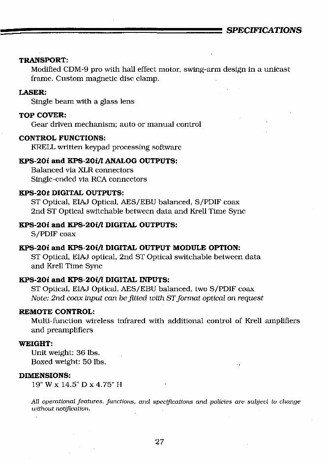
TRANSPORT:Modified CDM-9 pro with hall effect motor, swing-arm design in a unicastframe. Custom magnetic disc clamp.
LASER:Single beam with a glass lens
TOP COVER:Gear driven mechanism; auto or manual control
CONTROL FUNCTIONS:KRELL written keypad processing software
KPS-20i and KPS-201//ANALOG OUTPUTS:Balanced via XLR connectorsSingle-ended via RCA connectors
KPS-20t DIGITAL OUTPUTS:ST Optical, EIAj Optical, AES/EBU balanced, S/PDIF coax2nd ST Optical switchable between data and Krell Time Sync
KPS-20i and KPS-20i//DIGITAL OUTPUTS:S/PDIF coax
KPS-20i and KPS-20i//DIGITAL OUTPUT MODULE OPTION:ST Optical, EIAJ optical, 2nd ST Optical switchable between dataand Krell Time Sync
KPS-201 and KPS-20i//DIGITAL INPUTS:ST Optical, EIAJ Optical, AES/EBU balanced, two S/PDIF coaxNote: 2nd coax input can befitted with ST format optical on request
REMOTE CONTROL:Multi-function wireless infrared with additional control of Krell amplifiersand preamplifiers
WEIGHT:Unit weight: 36 lbs.Boxed weight: 50 lbs. ,~
DIMENSIONS:19" W x 14.5" D x 4.75" H
All operational features, functions, and specifications and policies are subject to changewithout notification.
27

WARRANTY AND SERVICE
THERE ARE NO USER-SERVICEABLE PARTS INSIDE ANY KRELL PRODUCT.
KRELL PLAYBACK SYSTEM-20 has a limited and transferable warranty of fiveyears for parts and labor and three years on trahsport related parts. Thewarranty period begins on the date of retail purchase,’ as noted on the retailsales slip provided by an authorized KRELL Dealer or Distributor, or on thewarranty registration card sent to KRELL. In the event adequate proof ofpurchase date is unavailable, the warranty period will begin on the date theunit was originally shipped from the factory. The original ship date can bedetermined by KRELL from the serial number.
The warranty for KRELL products is valid only in the country to which theywere originally shipped, through the authorized KRELL Distributor for thatcountry, and at the factory. There may be restrictions on, or changes toKRELL’s warranty because of regulations within a specific country. Pleasecheck with your Distributor for a complete understanding of the warranty inyour country.
Freight to the factory is your responsibility. Second day return freight withinthe United States is included in the warranty. If you have purchased yourKRELL product outside the United States and wish to have it serviced at thefactory, all freight and associated charges to the factory are your responsibility.Krell will pay return freight to the US-based freight forwarder of your choice.Freight and other charges to ship the unit from the freight forwarder to you arealso your responsibility.
The operating voltage of this unit is determined by the factory and can only bechanged by an authorized KRELL Distributor or at the factory. The voltage forthe KRELL PLAYBACK SYSTEM-20i in the USA can not be changed until sixmonths from the original purchase date. Any unauthorized voltage conversion,disassembly, component replacement, perforation of chassis, updates, ormodifications performed to the unit will void the warranty.
KRELL is not responsible for any damage incurred in transit. KRELL will fileclaims for damages as necessary for units damaged in transit to the factory.You are responsible to file claims for shipping damages during the returnshipment. ~ ~
28

The use of any packing material other than original is not recommended.KRELL may, at its discretion, pack a unit in new packing for the returnshipment and bill you for such packing if the unit was packed in non-standardpacking or the original packing is so damaged as to be unusable. Should youneed to purchase additional packaging please contact your authorized KRELLDealer, Distributor or KRELL for assistance.
IMPORTANT: If you think there are problems with your unit, please contact yourDealer, Distributor, or the factory immediately. Do not return any unit to KRELLfor repair without first calling to discuss the problem and to obtain a ReturnAuthorization number.
All operational features, functions, and specifications and policies are subjectto change without notification.
29

KRELL45 Connair Road ¯ Orange, CT 06477203’799-9954 ¯ Fax: 203-799-9796
Copyright 1995 KRELLP/N D960601600000