kp-lab knowledge practices laboratory – specification of
TRANSCRIPT

HAL Id: hal-00593211https://hal.archives-ouvertes.fr/hal-00593211
Submitted on 13 May 2011
HAL is a multi-disciplinary open accessarchive for the deposit and dissemination of sci-entific research documents, whether they are pub-lished or not. The documents may come fromteaching and research institutions in France orabroad, or from public or private research centers.
L’archive ouverte pluridisciplinaire HAL, estdestinée au dépôt et à la diffusion de documentsscientifiques de niveau recherche, publiés ou non,émanant des établissements d’enseignement et derecherche français ou étrangers, des laboratoirespublics ou privés.
KP-LAB Knowledge Practices Laboratory –Specification of end-user applications
Olli Alm, Patrick Ausderau, Merja Bauters, Markus Holi, Antti Hämäläinen,Hannu Markkanen, Eini Saarivesi, Benoit Rigolleau, Michal Racek, Ali
Rantakari, et al.
To cite this version:Olli Alm, Patrick Ausderau, Merja Bauters, Markus Holi, Antti Hämäläinen, et al.. KP-LAB Knowl-edge Practices Laboratory – Specification of end-user applications. 2009. �hal-00593211�

27490
KP-LAB
Knowledge Practices Laboratory
Integrated Project
Information Society Technologies
DII.8 M46 specification of end-user applications
Due date of deliverable: 30/11/2009Actual submission date:
Start date of project: 1.2.2006 Duration: 60 Months
Organisation name of lead contractor for this deliverable: Metropolia
Revision [0.5]
Project co-funded by the European Commission within the Sixth Framework Programme(2002-2006)
Dissemination LevelPU Public PUPP Restricted to other programme participants (including the Commission Services)RE Restricted to a group specified by the consortium (including the Commission Services)CO Confidential, only for members of the consortium (including the Commission Services)
IST-27490 (IP): KP-Lab – Knowledge Practices Laboratory D II.8
2
Contributor(s): Olli Alm Metropolia [email protected] Ausderau Metropolia [email protected] Bauters Metropolia [email protected] Holi Metropolia [email protected] Hämäläinen Metropolia [email protected] Markkanen Metropolia [email protected] Saarivesi Metropolia [email protected] Rigolleau AKKA [email protected] Ra ek PÖYRY [email protected] Rantakari PÖYRY [email protected] Tchoumatchenko TUS [email protected] Vasileva TUS [email protected] Locoro DIBE [email protected] Marina Scapolla DIBE [email protected]šek Babi TUK [email protected] Bednar TUK [email protected] Paralic TUK [email protected] Wagner TUK [email protected] Simonenko UPS [email protected] Sugibuchi UPS [email protected]
Editor: Hannu Markkanen, Olli Alm
Partner(s): 2. Metropolia, 4. AKKA, 5. POYRY, 7. TUS, 12. DIBE, 16. TUK, 20. UPS
Work Package: WPII − Knowledge Practices Environment
Nature of thedeliverable:
Report
Version history (of the main document)Version Date Author(s) Description0.1 24.11.2009 Markkanen First draft with chapter 1-40.2 04.12.2009 Alm KPE architecture0.3. 20.12.2009 Markkanen Overview of tool specifications0.4 06.01.2010 Markkanen Proof-reading and final edits.0.5 08.01.2010 Markkanen Compilation of annexes.1.0 12.01.2010 Markkanen Final edits.

IST-27490 (IP): KP-Lab – Knowledge Practices Laboratory D II.8
3
Executive summary
The present deliverable provides a high-level view on the new specifications of end userapplications defined in the WPII during the M37-M46 period of the KP-Lab project. This isthe last in the series of four deliverables that cover all the tools developed in the project, theprevious ones being D6.1, D6.4 and D6.6. This deliverable presents specifications for thenew functionalities for supporting the dedicated research studies defined in the latest revisionof the KP-Lab research strategy. The tools addressed are: the analytic tools (Data export,Time-line-based analyser, Visual analyser), Clipboard, Search, Versioning of uploadablecontent items, Visual Model Editor (VME) and Visual Modeling Language Editor (VMLE).
The main part of the deliverable provides the summary of tool specifications and thedescription of the Knowledge Practices Environment architecture, as well as an overview ofthe revised technical design process, of the tools’ relationship with the research studies, andof the driving objectives and the high-level requirements relevant for the presentspecifications. The full specifications of tools are provided in the annexes 1-9.

IST-27490 (IP): KP-Lab – Knowledge Practices Laboratory D II.8
4
Table of ContentsTable of Contents....................................................................................................................4Table of Tables .......................................................................................................................4Table of Figures ......................................................................................................................5List of Abbreviations ..............................................................................................................61 Introduction.....................................................................................................................72 Overview of the KPE and the present specifications ........................................................73 Technical design process ...............................................................................................11
3.1 Tool design within the KP-Lab co-design framework ............................................113.2 Specification documentation..................................................................................13
4 Tools’ relationship with the empirical research cases, driving objectives and the high-level requirements.................................................................................................................135 Overview of tools specifications....................................................................................16
5.1 Alternative process view........................................................................................175.2 Clipboard...............................................................................................................185.3 Data Export ...........................................................................................................195.4 Search ...................................................................................................................205.5 Time-line based analyser (TLBA)..........................................................................215.6 Versioning.............................................................................................................225.7 Visual analyser ......................................................................................................235.8 Visual Model editor ...............................................................................................245.9 Visual Modelling Language Editor ........................................................................25
6 Knowledge Practices Environment Architecture............................................................266.1 Functional view .....................................................................................................276.2 Implementation view .............................................................................................28
6.2.1 Tool layer ......................................................................................................296.2.2 Tools’ front-end service layer ........................................................................29
7 Conclusions and Future Work .......................................................................................328 References.....................................................................................................................32Annex 1. Alternative Process View specifications................................................................33Annex 2. Clipboard tool specifications..................................................................................49Annex 3. Data Export tool specifications...............................................................................67Annex 4. Search tool specifications.......................................................................................83Annex 5. Time-line based analyser (TLBA) specifications ....................................................95Annex 6. Versioning tool specifications .............................................................................. 120Annex 7. Visual analyser specifications .............................................................................. 147Annex 8. Visual Model editor specifications ....................................................................... 165Annex 9. Visual Modelling Language Editor specifications ................................................ 178
Table of TablesTable 1: KP-Lab tools included in DII.8 specifications and their relationship to the drivingobjectives, high-level requirements and empirical research cases. .........................................14Table 2: Empirical research cases’ need for new tool functionality. .......................................14Table 3: Overview of the driving objectives and high-level requirements that are relevantfor the tool functionalities specified in DII.8. ........................................................................15

IST-27490 (IP): KP-Lab – Knowledge Practices Laboratory D II.8
5
Table 4: Main functionality and planned releases of tools with specifications in DII.8...........16Table 5: Overview of the KP-Lab Tools’ Front-end Services. ...............................................30Table 6: Overview of the Real Time Data Access Services....................................................31
Table of FiguresFigure 1: Part of the project intranet’s section for DII.8 deliverable.........................................7Figure 2: End user view of the KPE components.....................................................................8Figure 3: Overview of the KP-Lab co-design process model [7]. ...........................................12Figure 4: The functional view of the KP-Lab tools’ architecture............................................27Figure 5: The implementation view of the Knowledge Practices Environment Architecture. .28

IST-27490 (IP): KP-Lab – Knowledge Practices Laboratory D II.8
6
List of AbbreviationsAPI Application Programming InterfaceASDT Activity System Design ToolsCASS Contextual Activity Sampling SystemDO Driving ObjectiveDoW Description of WorkEMF Eclipse Modeling FrameworkFMS Flash Media ServerGUI Graphical User InterfaceHLR High-Level RequirementHPA History and Participation AwarenessHTTP Hypertext Transfer ProtocolIMS IMS Global Learning Consortium (IMS = Instructional Management
Systems)KAS Knowledge Analysis ServiceKPE Knowledge Practices EnvironmentM2T Meeting Management ToolSCORM Shareable Content Object Reference ModelSMAT Semantic Multimedia Annotation ToolsReST Representational State TransferRTMP Real Time Messaging ProtocolRTMPT Real Time Messaging Protocol Tunneling (via http)SKOS Simple Knowledge Organisation SystemsSWKM Semantic Web Knowledge MiddlewareSSp Shared SpaceTLBA Time-line Based AnalyserTLO Trialogical Learning OntologyUC Use CaseUCI Uploadable Content ItemUM User ManagementUS Usage ScenarioUT User TaskVME Visual Model EditorVMLE Visual Model Language EditorWP Work PackageXML Extensible Mark-up Language

IST-27490 (IP): KP-Lab – Knowledge Practices Laboratory D II.8
7
1 IntroductionThis deliverable presents the new specifications of end user applications defined in theWPII during the M37-M46 period of the KP-Lab project. It covers new tools as well as thesignificant enhancements and extensions to the earlier tool releases. The specifications donot, however, include tools that will have only minor improvements e.g. in usability. Thedeliverable follows the same way of description as the previous tool specificationsdeliverable D6.6 [6].
The specifications of single tools are provided in the annexes 1-9. These and the possiblelater revisions of specifications are also available in the DII.8 folder of the KP-Lab intranet(http://www.kp-lab.org/intranet/work-packages/wp6/result/dii-8-m46-specification-of-end-user-applications) in the folder “Specifications of single tools”, see Figure 1.
Figure 1: Part of the project intranet’s section for DII.8 deliverable.
2 Overview of the KPE and the present specificationsThis chapter provides an overview of the tools with specifications in the presentdeliverable. The chapter is organised according to the categorisation of tools in the WPII

IST-27490 (IP): KP-Lab – Knowledge Practices Laboratory D II.8
8
description of DoW4.1. Further details on the tool specifications can be found in chapter 5and in the annexes 1-9.
KPE provides a set of integrated tools and functionalities for sustained collaborativeworking with shared epistemic objects (artefacts, processes, practices). KPE providesvirtual working spaces, called shared spaces, for the collaborative work, enables viewingthe knowledge objects and their relations from different perspectives and supports object-bound development of all items in a shared space. Various tools and functionalities arehighly integrated in the basic views to enable versatile and flexible connection,organization and reflection of all information related to the knowledge objects, processesand people concerned. The end user view of the KPE is depicted in the Figure 2.
Figure 2: End user view of the KPE components.
KPE is composed of the following views and sets of tools:• Shared Space views allow for viewing and accessing the information contained in a
shared space in flexible manner (network view, content view, process view,community view and tailored view).
• Common tools refer to the tightly integrated tools of KPE, available inside a sharedspace, for working with knowledge artefacts. Examples of common tools are chat,commenting, and semantic tagging.
• Optional tools are loosely integrated applications that can be selected by the user tobe available in a shared space, such as ASDT, calendar, and data export.

IST-27490 (IP): KP-Lab – Knowledge Practices Laboratory D II.8
9
• Support tools provide generic supplementary functionality used in/by the SharedSpace views and the other tools, such as awareness, help, and search.
In addition, there are three stand-alone applications that are used separately from the KPE,namely Map-It, and CASS Query and CASS Memo. The development of these tools hasbeen stopped as requested after the 3rd project review.
The earlier specification deliverables produced in the WP6 (i.e. d6.1, D6.4 and D6.6) covermost of the KPE functionality. The present deliverable provides specifications for theremaining new functionalities, which focus on supporting dedicated research studiesdefined in the latest KP-Lab research strategy. These functionalities are as follows:
o Alternative process viewo Analytic tools: Data export, Time-line-based analyser, Visual analysero Clipboard for re-using of shared spaces and artefactso Search/saving searcheso Versioning of the uploadable content itemso Visual Model Editor (VME) and Visual Modeling Language Editor (VMLE)
Alternative process view introduces a new way for visualising knowledge creationprocesses in the KPE. The process view of KPE provides the user interface for managingand visualizing of the knowledge processes within shared spaces. Process planning throughdefining tasks and drafting visual process representations allows users to explicate theirprocess composition and promotes responsibility and ownership over their decisions andactions. The current process view of KPE is realised as a Gantt chart. In the alternativevisualization users can, however, visualize the process structure and workflow by usingimages and pre-defined shapes and arrows. The rationale for development of thealternative process view is that the knowledge practices and processes need to be veryflexible, enabling innovative styles of working and learning, and they are dynamic innature. Spatial representation and emphasis on relationships between tasks as well as tasksand contents is especially useful in educational settings, where the chronology of the workis not essential, but there is a requirement to see connections, associations and causalrelations between the various elements of the process.
Analytic tools provide tools for two main categories of analytic facilities: 1) Data exporttool for automatic data collection for the analysis in third party tools and 2) Timeline-basedanalyser and Visual analyser for integrated reflection on knowledge creation processesand their analysis. Research in related areas has produced several existing approaches toanalysis of processes but to our knowledge there is no particular approach focused onknowledge creation processes, i.e. trying to analyze the employed knowledge practices,which we see as major advancement with respect to the state-of-the-art processes analysistools.
Data export tool allows researchers and teachers to extract summary tables of useractivities from the KPE for on-line investigation, and to export them for elaborations withstatistical analysis packages. It gathers data about activities taking place in the KPE andextracts data from three repositories of the KP-Lab system, namely from the awarenessrepository, the user database and the knowledge repository. Data export tool has been partof the KPE since M24 release with subsequent extensions in later releases (see [2]). Thenew features specified in the present deliverable include adding graphical views to the

IST-27490 (IP): KP-Lab – Knowledge Practices Laboratory D II.8
10
“Social Networks Analysis” function and exporting of data compatible with Referencemodel.
Timeline-based analyser (TLBA) allows users to display chronologically events that wererecorded by the KPE tools, to design and store possible external events which could nothave been recorded by the KPE tools and to define ‘patterns’ of actions that can beidentified in the historical data. In contrast to Visual Analyser and Data Export tools,TLBA brings chronological overview of user actions into the user interface, which enablesusers to see and explore what kind of activities were performed on certain objects in theshared space of interest. Time-line view in its initial form has been already released in M36as ASDT Analysis Application (see [2]). The new functionalities in the present deliverableare the possibility to add external events, the possibility of commenting on user actions,defining of action ‘patterns’, searching the history of stored actions for defined patternsand export functionalities.
Visual analyser is a completely new tool that allows users to analyze participation andactivities within past or ongoing knowledge creation processes, by visually representingthem based on information stored in the produced logs. More precisely, it visualizesfrequencies of object-related activities in KPE and provides detailed information on thenature of the activities performed on particular knowledge objects. These visualizationsstimulate teachers and students to reflect on object progression, and on their teaching andlearning practices.
Clipboard tool allows users to re-use shared spaces and artefacts within KPE by providingthe copy-paste functionality of shared spaces, tasks, vocabularies and most types of contentitems. The rationale is to enable users to systematically build on previous work as well asto disseminate and share effective knowledge practices. The clipboard will be available inall shared space views of KPE, The clipboard tool offers to the research cases the barebones minimum functionality of the re-use library tool envisaged in the D6.6 [6]. The cutdown of the re-use functionality was done to reduce the technical development work asrequested after the third project review.
Search tool will be extended with the functionality to save search results and criteria,which was planned in iteration 2 of the tool (see [6], p.31). Due to the cut-down of theresources after the third project review, this is the only new functionality of the search toolnecessary for the research cases.
Versioning tool allows users to create new versions and replace latest version of theuploadable content items, which are files that can be uploaded into the KP-Lab contentrepository (such as office documents, pictures, SCORM/IMS packages). The user is alsoable to see detailed information on specific versions. Versioning will support teachers andstudents to review and analyze their collaborative editing activities by enabling the tracingof changes in their knowledge artefacts. The possibility to keep track of changes and revertto previous versions of content items supports the exploratory creation and use of artefacts.
Visual Model Editor (VME) and Visual Modelling Language Editor (VMLE) tools draw onthe recent ideas for a pragmatic semantic web and consider modeling as an inherentlyepistemic activity that goes beyond the mere representation of what is already known andwhat can be agreed upon. The vision behind these tools is to provide users with thepossibility to create their own conceptual tools and thereby to advance pre-existing

IST-27490 (IP): KP-Lab – Knowledge Practices Laboratory D II.8
11
perspectives. The two tools provide users with a flexible and easy to use but stillsemantically powerful tool for the creation of visual models and their underlying modelinglanguages. The VME tool will be extended with the functionality for retrieving andanalysing information on activities performed on a visual model. The first prototype of theVMLE (released in M36) tool will be redesigned in order to achieve the functionalcompleteness and acceptable performance required in the research cases. This includesdesigning of a new data model as well as revision of the architecture and implementationof the front end service. From the functional point of view, a new history analysis andexport capabilities are needed.
3 Technical design processThis chapter gives an overview of how the tool design is organised as part of the KP-Labco-design framework and of the structure of the tool specification.
3.1 Tool design within the KP-Lab co-design framework
The software development process in WPII has been organised during the current projectperiod as described in the D2.3 [7]. From the tool development perspective, there are nosignificant changes compared with the process described in the previous specificationsdeliverable D6.6 [6].
Figure 3 provides an overall view of the KP-Lab R&D activities from the co-designperspective. The software specifications presented in this deliverable are the result of workwithin the User Requirements Specification and the Technical development activities. Thesoftware specification documents are high-level design documents that are composed ofthe use cases and the overall technical design in terms of the architecture, user interfaceand front-end services of the tool.

IST-27490 (IP): KP-Lab – Knowledge Practices Laboratory D II.8
12
Figure 3: Overview of the KP-Lab co-design process model [7].
The system usage scenarios and use cases define the user requirements for the software. Asystem usage scenario illustrates how the user will interact with the system/tools in orderto accomplish certain tasks. The system usage scenario describes typical sequences ofinteraction as envisioned by the designers and gives an idea of the added value for the user.The scenarios are written in plain English and as such are an informal way of writing usecases. The aim of this intermediate artefact is to facilitate the collaboration betweenpedagogical and technical partners when analyzing requirements. The use cases arederived from the system usage scenarios and describe the interactions between a user andthe tool as a sequence of operations and events. Each system usage scenario results inwriting one or several use cases. Chapter 5 provides the summary of usage scenarios anduse cases for the specifications in present deliverable. Further details can be found in thetool specification documents available in the annexes 1-9.

IST-27490 (IP): KP-Lab – Knowledge Practices Laboratory D II.8
13
Based on the software requirements specifications the WPII partners produce the varioustools and integrate them, in collaboration with WPIII partners, into the KP-Lab systemaccording to the tool development roadmap described in the chapter 5 of presentdeliverable. Each tool has its own iterative development roadmap and release schedule, andthere is one common production release in M48 for all tools. Before the tools are used aspart of the research studies or other pilots, the prototypes of new tools/ functionality arechecked for bugs and usability problems by the pedagogical partners using the KP-Labsystem available in the development environment1.
WPIII provides the technical and the semantic knowledge services required by the tools.KP-Lab system is built using continuous integration server in order to reduce integrationproblems and allowing developers to provide (upgrades and bug fixes of) tools morerapidly.
3.2 Specification documentation
The specifications in this deliverable have been written in a common template that waspublished in the project intranet. The template is structured into four major chapters asfollows:1. Introduction describes the purpose of the document, the scope of the software, the tool
roadmap in terms of milestones and functionality of the releases, the summary of newfunctionality covered by the present specifications and the definitions needed tounderstand the specifications.
2. User requirements outline first tool’s relationship with KP-Lab research studies,Driving Objectives and High-Level Requirements. An overview of the system usagescenarios for the tool and a reference to the related requirements document is givennext. These leads way to the description of the use cases which are the other majorcontent of the specifications document.
3. Technical design describes tool’s software architecture in the context of KPEapplication architecture described in the chapter 6 of the present deliverable, the designof tool’s GUI and the front-end services (including their use of the KP-Lab platformservices), and the collaboration with other tools.
4. References conclude the specification document.
4 Tools’ relationship with the empirical research cases,driving objectives and the high-level requirements
This chapter describes the rationale for tool development by providing a summary of thetools’ relationship with the empirical research cases and the conceptual tools of co-design,i.e. the driving objectives (DOs) and high-level requirements (HLRs). For detaileddescription of DOs and HLRs, please refer to [4].
Table 1 summarizes the relationship between the tool specifications available in the presentdeliverable and the DOs, HLRs and the empirical research cases. Short description of thetool’s main purpose is provided as well.
1 Login at http://mielikki.mobile.evtek.fi/shared-space/

IST-27490 (IP): KP-Lab – Knowledge Practices Laboratory D II.8
14
Table 1: KP-Lab tools included in DII.8 specifications and their relationship to the drivingobjectives, high-level requirements and empirical research cases.
Tool Description of the new functionality Related research cases DOs and HLRsAlternativeprocess view
Visualisation of the process structure andworkflow by using images and pre-definedshapes and arrows.
Case 2 DO8: HLR8.8
Clipboard Copy-pasting of shared spaces andcontent items.
Case 1, 2, 3, 4 DO3: HLR3.1
Data export Graphical views for the “Social NetworksAnalysis” function, export of datacompatible with Reference model.
Case 1,2,3,4 DO9: HLR9.2DO13: HLR13.5, HLR13.6,HLR13.7
Search Saving criteria and results of semanticsearches.
Case 1,2,4 DO1: HLR1.4DO4: HLR4.1DO8: HLR8.6
Time-line basedanalyser (TLBA)
Chronological overview of user actions onKPE objects in a shared space.
Case 1, 2, 3, 4 DO8: HLR8.7DO9: HLR9.1, HLR9.2DO13; HLR13.5, HLR13.6
Versioning Versioning of content items uploaded inthe KPE.
Case 1, 2, 3, 4 DO1: HLR1.1, HLR1.2DO9: HLR9.1, HLR9.2
Visual analyser Visualisation of the frequencies of object-related activities in KPE.
Case 1,2,4 DO9: HLR9.2DO13: HLR13.5. HLR13.6
Visual ModelEditor (VME)
Creation of visual models based on thelanguages created with the VMLE tool.
Case 3 DO9: HLR9.1, HLR9.2DO13: HLR13.5, HLR13.6
Visual ModellingLanguage Editor(VMLE)
Creation of modelling languages for use inVME tool.
Case 3 DO2: HLR2.2, HLR2.5DO4: HLR4.3, HLR4.4DO6: HLR6.1, HLR6.2, HLR6.3DO9: HLR9.1, HLR9.2DO13: HLR13.5, HLR13.6
By related research cases we refer to those empirical research cases that investigate(among other things) the use of tools that target the high-level requirements relevant to thetool. There are four research cases entitled in D3.2 [3] as follows:
Case 1: Trialogical work in higher education; creation and use of knowledge objects inknowledge creation practices.
Case 2: Knowledge creation practices in customer projects in higher education.Case 3: Conceptual modelling in Design Projects.
Case 4: Producing document management solutions and practices for distributed worksettings – Perspectives of KPE usage in two work organizations.
As a response to the request in the third project review, Table 2 provides a cross-referencebetween the research cases and the tools included in the present specifications.
Table 2: Empirical research cases’ need for new tool functionality.Empirical research case Requires new functionality in tool
Case 1: Trialogical work in higher education; creation anduse of knowledge objects in knowledge creation practices.
Clipboard, Data export, Search, TLBA, Versioning, Visualanalyser
Case 2: Knowledge creation practices in customer projectsin higher education.
Alternative process view, Clipboard, Data export, Search, TLBA,Versioning, Visual analyser
Case 3: Conceptual modelling in Design Projects Clipboard, Data export, TLBA, Versioning, VME, VMLECase 4: Producing document management solutions andpractices for distributed work settings
Clipboard, Data export, Search, TLBA, Versioning, Visualanalyser

IST-27490 (IP): KP-Lab – Knowledge Practices Laboratory D II.8
15
The overview of the DOs and HLRs referred to in the Table 1 is given in the Table 3. Thedescription of the DOs and HLRs is provided in the D2.4 [4] and the more detailed accountof the relationships between the tools and DOs and HLRs can be obtained from the toolspecifications available in the annexes 1-9 of the present deliverable and from project’sinternal working documentation that the annexes refer to.Table 3: Overview of the driving objectives and high-level requirements that are relevant for
the tool functionalities specified in DII.8.
DO1 Users are provided with a collaborative environment where they can work on shared artefactsHLR1.1 Users can create structure and share various artefacts (e.g. sketches, various kinds of texts, video and audio-
files, models as well as ontologies) in one place.HLR1.2 Users are able to view the artefacts and their relations from different perspectives.HLR1.4 Users can search artefacts within and outside the shared environment using full text, metadata or domain
ontologies.DO2 Users are provided with a customizable tool suite for working on shared artefactsHLR2.2 The tools are generic enough to allow users to use them in various ways of working, e.g., personalization of the
tools and adaptation to different domain knowledge.HLR2.5 Users can import and export artefacts and access data across the tools integrated or connected to the KP
Environment.DO3 Users are provided with support for the re-use of shared artefacts and structuresHLR3.1 Users can re-use process structures and artefacts.DO4 Users can describe the semantics of artefacts and their relationsHLR4.1 Users can categorise, classify and cluster artefacts in different manners.HLR4.3 Users can work with multiple conceptual models (vocabularies or visual modelling languages) in parallel.HLR4.4 Users are able to save and share conceptual models (e.g. vocabularies and visual models)DO6 Users can develop and use their own conceptual modelsHLR6.1 Users can modify existing or create new visual modelling languages, ontologies and vocabularies.HLR6.2 Users can refine, make proposals and give objections on modelling languages, ontologies and vocabularies
while working on the respective knowledge representations and visual models.HLR6.3 Users can share and integrate different visual modelling languages, ontologies and vocabularies.DO8 Users can plan, organize and manage tasks collaborativelyHLR8.6 Users can search the content and metadata using full text or semantic metadata search for planning and
reflecting on activities or both.HLR8.7 Users are provided with a customized analysis of groups’ working processes (e.g. identification of typical
sequences of actions or interesting rules).HLR8.8 Users can choose between different types of process structure visualizations (e.g. project based or progressive
inquiry).DO9 Users are provided with history on content development and work process advancementHLR9.1 Users can track the evolution and changes of knowledge objects and find out their authors and contributors
(sequences of performed steps in time, incl. versioning)HLR9.2 Users are provided with customized summaries about the knowledge objects available within the shared
environment (e.g. users might request an overview of the tasks completed within the last 2 weeks or theinteractions of people within a shared workspace)
DO13 Users can collect data about activities and interactions systematically and over longer periods of timeHLR13.5 Users can customise the way they want to retrieve wanted data for analysis.HLR13.6 Users are provided with summative information on performed actions (e.g. added comments, created tasks,
modifications in metadata, background materials for decisions, etc.).

IST-27490 (IP): KP-Lab – Knowledge Practices Laboratory D II.8
16
5 Overview of tools specificationsThis chapter provides an overview of the specifications included in the present deliverable.For each tool, a short description of its purpose is given, followed by the summaries of thefunctionality covered by the present specification, of the requirements (as a list of systemusage scenarios and use cases), as well as of the development roadmap
The description and rationale of the new functionalities was presented in the chapter 2.Table 4 provides the summary of the milestones in the tool roadmaps for DoW4 period ofthe project, as well as short description of the major functionality of the releases. Shortoverview of the specifications is presented in the rest of this chapter and the details in thetool specifications documents available in the annexes 1-9 and in the KP-Lab projectintranet (direct web links for each tool are provided below).
Table 4 Main functionality and planned releases of tools with specifications in DII.8.Tools Milestones Release functionality
v1.0: M45 Specification, M46 Prototype,M48 Production release
Full functionality for creating and modifying alternativeprocess view, and for using alternative process viewelements in content and tailored views.
Alternative processview
v1.1: M56 Final release Improvements and bug fixes of v1.0 based on the usertrials.
v1.0 M44 Specifications, M46 Prototype, M48Production release
Copying and pasting a shared space, copying andpasting elements from a shared space to another.
Clipboard
v1.1: M56 Final release Improvements and bug fixes of v1.0 based on the usertrials.
v3.0: M40 prototype, M42 Productionrelease
Extensions of the export functionalities according to theusers’ priorities on the requirements already collectedin M33 specifications and integration of graphical viewfor “Social Networks Analysis”
Data Export
v3.1 M47 Prototype, M48 Final release Exporting data in a format compatible with ReferenceModel. Improvements and bug fixes of v3.0 based onthe user trials.
v1.1: M46 Maintenance release. Improvements and bug fixes of v1.0 based on the usertrials.
v2.0: M46 Specification, M47 Prototype, M48Production release
Saving of search results.
Search
v2.1: M56 Final release. Improvements and bug fixes of v2.0 based on the usertrials.
v0.1: M44 Prototype release Basic functionalities for launching application fromKPE, for displaying user actions and for getting specificinformation about particular action.
Time-line basedanalyser (TLBA)
v1.0: M45 technical specification, M47Prototype, M48 Production release
Stable release with extensions for adding externalevents, for commenting on user actions, for definingaction ‘patterns’, for searching the history of storedactions for defined patterns and for exportfunctionalities.
v1.0 M41 Requirements, M45 Specifications,M47 Prototype, M48 Production release
Creating new versions of the uploadable content items,seeing detailed information of specific versions.
Versioning
v1.1: M56 Final release Improvements and bug fixes of v1.0 based on the usertrials.
v1.0: M40: Specification, M42 Prototype,M44 Release
Basic functionality for request, summary visualization inthe form of bar chart or line chart, as well as for the firstintegration into KPE (as a plug-in).
Visual analyser
v2.0: M44: Specification, M46 Prototype,M48 Release
Improved request formulation, improved user interfacewith new analysis attributes, interactive summary

IST-27490 (IP): KP-Lab – Knowledge Practices Laboratory D II.8
17
Tools Milestones Release functionalityvisualization, more flexible filtering of events, possibilityto export (save) the resulting summaries and theirvisualization in a file, final integration into KPE.
v2.1: M56 Final release Improvements and bug fixes of v2.0 based on the usertrials.
v2.2: M46 Specification, M47 Prototype, M48Production release.
Retrieving information on activities performed on avisual model (history), export of visual models.
Visual Model Editor(VME)
v2.3: M56 Final release. Improvements and bug fixes of v2.2 based on the usertrials.
v2.0: Updated requirements, M39 Prototype,M40 Production release
Basic VMLE functions for browsing, creating, copying,commenting and editing VMLs. Adding, editing,commenting and deleting concepts and relations to aVML
v3.0: M40 Specification, M42 Prototype, M44Production release
Advanced VMLE functions for comparing visualmodelling languages, updating a visual modelaccording to changes in the VML.
v3.2: : M46 Specifications, M48 Productionrelease
Optimized data model and front-end services. Newfunctionality for history analysis and export capabilities.
Visual ModellingLanguage Editor(VMLE)
v3.3: M56 Final release. Improvements and bug fixes of v3.2 based on usertrials.
5.1 Alternative process view
Process View and Alternative Process View provide the user interfaces for managing andvisualizing knowledge processes within KPE shared spaces. The Process View visualizesthe process by using a Gantt chart, in a time-dependent manner. Alternative Process Viewprovides a support for other models and forms of planning processes: it supportsvisualization and coupling of different activities. Users can visualize the process structureand workflow by utilizing predefined bitmap images and custom visual shapes to associatethe activities to different Process Entities.
The Alternative Process View has an UI to support following tasks in the KPE system:• Gives user the possibility to draw a non-temporal visualization of the process• Provides support for enhancing the process visualization with an existing bitmap
picture• Associates and organizes existing tasks to a specific process phase.
The present deliverable describes specifications for the following functionality of the tool:• Creating and modifying an Alternative Process View• Using Alternative Process View elements in the Content View• Focusing on a certain process element in a Tailored View• Displaying the process elements of the Alternative Process View in the GANTT
Chart
The requirements for the above functionalities are described by five system usagescenarios and eight use cases:System usage scenarios
• US-APV-1-2008-11: Creating an Alternative Process View• US-APV-2-2008-11: Modification of an Alternative Process View• US-APV-3-2008-11: Using Alternative Process View elements in the Content
View

IST-27490 (IP): KP-Lab – Knowledge Practices Laboratory D II.8
18
• US-APV-4-2008-11: Focusing on a certain process element (Tailored View)• US-APV-5-2008-11: Displaying the Process Elements in the GANTT Chart
Use cases• UC-APV-01-2009-11: Uploading the background image for the process• UC-APV-02-2009-11: Creating the process workflow• UC-APV-03-2009-11: Associating tasks to process entities• UC-APV-04-2009-11: Modifying process visualization• UC-APV-05-2009-11: Removing process objects• UC-APV-06-2009-11: Showing the detailed information of the process object• UC-APV-07-2009-11: Showing the process entities in the Process View• UC-APV-08-2009-11: Showing the process entities in the Content Item View
The current roadmap of the Alternative Process View has two iterations as follows:• Iteration 1: First version of the full functionality. Release v1.0
Milestones: M45 Specification, M46 Prototype, M48
• Iteration 2: Final version including improvements and bug fixes based on the usertrials. Release v1.1.Milestones: M56 Production release
The specifications document for the Alternative Process View is available in annex 1, andin the project intranet at: http://www.kp-lab.org/intranet/work-packages/wp6/result/dii-8-m46-specification-of-end-user-applications/specifications-of-single-tools/process-view
5.2 Clipboard
Clipboard tool provides new functionality for re-using KPE objects by allowing users tocreate new objects starting from existing ones by copy-pasting. The following objects aresupported:
• Shared Spaces• Tasks• Vocabularies• Content Items
o Uploadable File, Web link, Note, Sketch, SCORM/IMS file, Wiki pages.
The clipboard will be available in all shared space views of KPE, The clipboard tool offersto the research cases the bare bones minimum functionality of the re-use library toolenvisaged in the D6.6 [6].
The requirements for the clipboard functionalities are described by two system usagescenarios and two use cases:System usage scenarios
• US-Clipboard-1-2009-11: Copying a Shared Space and pasting it as a new SharedSpace
• US-Clipboard-2-2009-11: Copying an element or elements (e.g. Content Items,vocabularies) and pasting them in another Shared Space.
Use cases• UC-Clipboard-1-2009-11: Copying and pasting a Shared Space

IST-27490 (IP): KP-Lab – Knowledge Practices Laboratory D II.8
19
• UC-Clipboard-2-2009-11: Copying and pasting elements from a Shared Space toanother.
The current roadmap of the Clipboard tool has two iterations as follows:• Iteration 1: First version of the full functionality. Release 1.0.
Milestones: M44 Specifications, M46 Prototype Release, M48 Production release
• Iteration 2: Final version with improvements and bug fixes based on the user trials.Release 1.1.Milestones: M56 Production release.
The specifications document for the Clipboard tool is available in annex 2 and in theproject intranet at: http://www.kp-lab.org/intranet/work-packages/wp6/result/dii-8-m46-specification-of-end-user-applications/specifications-of-single-tools/clipboard
5.3 Data Export
Data export tool allows researchers and teachers to extract summary tables of useractivities from the KPE for on-line investigation, and to export them for elaborations withstatistical analysis packages. It gathers data about activities taking place in the KPE andextracts data from three repositories of the KP-Lab system, namely from the awarenessrepository, the user database and the knowledge repository. Data export tool has been partof the KPE since M24 release with subsequent extensions in later releases (see [2]).
The present deliverable describes specifications of the Data Export tool which aims atimproving the M36 release on the basis of the feedback from tests and evaluation andextending the tool in terms of graphical views to the “Social Networks Analysis” functionand exporting of data compatible with Reference model. The requirements for thesefunctionalities are described by six system usage scenarios and three use cases introducedin D6.6 [6] and updated in the present deliverable:System usage scenarios
• US-DataExport-1-2008-11: Retrieving data of user activity in a shared space• US-DataExport-2-2008-11: Retrieving data of content items• US-DataExport-3-2008-11: Retrieving data of tasks• US-DataExport-4-2008-11: Social networks content item analysis and task analysis• US-DataExport-5-2008-11: Retrieving "User Action Log" summary for analysis• US-DataExport-6-2008-11: Retrieving "User Action Log" of detailed analysis of
users actionsUse cases
• UC-DataExport-1-2008-11: User opens the data export GUI from within sharedspace.
• UC-DataExport-2-2008-11: User selects the type of Data Export Analysis.• UC-DataExport-3-2008-11: User looks at the results and can download them.
The current roadmap of the Data Export Tool has one finished and two planned iterationsas follows:
• Iteration 1: Feasibility study and prototyping. Release v1.0 (M24)

IST-27490 (IP): KP-Lab – Knowledge Practices Laboratory D II.8
20
• Iteration 2: Facilitating the reading of the data exported by the tool and extendingthe analysis tables. Improvements of the GUI and extensions of “Social NetworkAnalysis” and “User Action Log" functionalities. Release v2.1.
o Milestones: M32 specifications, M33 Prototype v2.0, M36 Productionrelease.
• Iteration 3: Extensions of the export functionalities according to the users’ prioritieson the requirements already collected in M33 specifications and integration ofgraphical view for “Social Networks Analysis”. Release v3.0
o Milestones: M40 Prototype, M42 Production release.• Iteration 4: Final release with the possibility of exporting data in a format
compatible with Reference Model. Release v3.1.o Milestones: M47 Prototype, M48 Production release.
The specifications document for the Data Export Tool is available in annex 3 and in theproject intranet at: http://www.kp-lab.org/intranet/work-packages/wp6/result/dii-8-m46-specification-of-end-user-applications/specifications-of-single-tools/data-export-tool
5.4 Search
The Search tool enables advanced faceted search based on the metadata and content ofartefacts (content items). Search tool will be extended with the functionality to save searchresults and criteria, which was planned for the iteration 2 of the tool (see [6], p.31). Due tothe cut-down of the resources after the third project review, this is the only newfunctionality of the search tool necessary for the research cases. The requirements for thisfunctionality are described by one system usage scenarios and two use cases:System usage scenarios
• SUS-Search-4-2009-11: Saving search criteria and results.Use cases
• UC-Search-04-2009-11: User saves search criteria and results.• UC-Search-05-2009-11: User opens the saved search object (content item
organizer).
The current roadmap of the Search Tool has two finished and two planned iterations asfollows:Iteration 1: Basic free-term and faceted semantic search. Release v1.0
• Milestones: M33 Specification, M34 Prototype, M36 Release.Iteration 2: Improvements and bug fixes based on the user trials. Release v1.1
• Milestones: M46 Release.Iteration 3: Saving of search results. Release v2.0
• Milestones: M46 Specification, M47 Prototype, M48 Production release.Iteration 4: Final version with improvements and bug fixes based on user trials. Release2.1.
• Milestones: M56 Production release.
The specifications document for the new functionalities in iteration 3 of the Search Tool isavailable in annex 4 and in the project intranet at:

IST-27490 (IP): KP-Lab – Knowledge Practices Laboratory D II.8
21
http://www.kp-lab.org/intranet/work-packages/wp6/result/dii-8-m46-specification-of-end-user-applications/specifications-of-single-tools/search-1
5.5 Time-line based analyser (TLBA)
Timeline-based analyser (TLBA) is a tool that allows users to display chronologicallyevents that were recorded by the KPE tools, to design and store possible external eventswhich could not have been recorded by the KPE tools and to define ‘patterns’ of actionsthat can be identified in the historical data.
Time-line view in its initial form has been already released in M36 as ASDT AnalysisApplication (see [2]), which included the basic functionalities, such as launchingapplication from KPE, displaying user actions, and getting specific information aboutparticular action. It was designed and implemented in such a way that it is able to visualizenot only ASDT objects but all KPE objects. The additional functionalities planned for theTLBA in the present deliverable are:
• adding external events to the timeline• commenting user actions on knowledge objects• defining of actions ‘patterns’• searching the history of stored actions for defined patterns• exporting of TLBA view functionalities.• storing and loading TLBA settings.
The requirements for the clipboard functionalities are described by 10 system usagescenarios and 19 use cases:System usage scenarios
• US-TLBA-1-2009-09: Viewing all events on the timeline that have been performedon certain objects in a shared space.
• US-TLBA-2-2009-09: Viewing all events on the timeline that a user has performedon objects in a shared space.
• US-TLBA-3-2009-09: Viewing all events on the timeline that have been performedon tasks as well as on objects that are associated with the selected task.
• US-TLBA-4-2009-09: Exploring the evolution and history of a shared space on thetimeline.
• US-TLBA-5-2009-09: Exploring and comparing the evolution and history ofdifferent shared spaces on the timeline (M48).
• US-TLBA-6-2009-09: Adding external events to the timeline (M48).• US-TLBA-7-2009-11: Adding comment to the object’s action (M48).• US-TLBA-8-2009-11: Working with patterns (M48).• US-TLBA-9-2009-11: Exporting TLBA view (M48).• US-TLBA-10-2009-11: Storing and loading TLBA settings (M48).
Use cases• UC-TLBA-01-2009-11: User launches TLBA from Shared Space context-menu• UC-TLBA-02-2009-11: User launches TLBA from within the KPE tools drop
down menu• UC-TLBA-03-2009-11: User opens-up the TLBA from within the object’s context-
menu

IST-27490 (IP): KP-Lab – Knowledge Practices Laboratory D II.8
22
• UC-TLBA-04-2009-11: User opens-up TLBA application from within the task’scontext-menu
• UC-TLBA-05-2009-11: User highlights all actions performed by one person fromcommunity view
• UC-TLBA-06-2009-11: User highlights object’s evolution path in TLBA• UC-TLBA-07-2009-11: User highlights all actions performed by one person in
TLBA• UC-TLBA-08-2009-11: User explores details of an action• UC-TLBA-09-2009-11: User launches KPE content view• UC-TLBA-10-2009-11: User reads action’s comment (M48)• UC-TLBA-11-2009-11: User launches TLBA to compare several Shared Spaces
(M48)• UC-TLBA-12-2009-11: User adds external event into the timeline (M48)• UC-TLBA-13-2009-11: User comments on object action (M48)• UC-TLBA-14-2009-11: User defines actions pattern (M48)• UC-TLBA-15-2009-11: User loads actions pattern (M48)• UC-TLBA-16-2009-11: User searches for the pattern occurrences (M48)• UC-TLBA-17-2009-11: User exports current TLBA view (M48)• UC-TLBA-18-2009-11: User saves current TLBA settings (M48)• UC-TLBA-19-2009-11: User loads TLBA settings (M48)
The planned iterations for the TLBA tool are as follows:Iteration 1: First prototype version with basic functionalities. Release 0.1.
• Milestones: M44 Prototype releaseIteration 2: Stable release including extensions to add external events, the possibility ofcommenting on user actions, defining of action ‘patterns’, searching the history of storedactions for defined patterns and export functionalities. Release 1.0.
• Milestones: M45 Technical specification, M47 Prototype, M48 Production releaseIteration 3: Final version with improvements based on the user trials. Release 1.1
• Milestones: M56 Production release.
The specifications document for the TLBA tool is available in annex 5 and in the projectintranet at: http://www.kp-lab.org/intranet/work-packages/wp6/result/dii-8-m46-specification-of-end-user-applications/specifications-of-single-tools/tlba-tool
5.6 Versioning
Versioning tool allows users to create new versions and replace latest version of theuploadable content items (UCI), which are files that can be uploaded into the KP-Labcontent repository (such as office documents, pictures, SCORM/IMS packages). Thefollowing functionalities will be implemented:
• The user can create versions in uploadable Content Items.• The user can replace latest version of the uploadable Content Item.• The user can see certain information of the versions.
• Creating new version of the UCI• Replacing the latest version of the UCI

IST-27490 (IP): KP-Lab – Knowledge Practices Laboratory D II.8
23
• Getting information of the UCI versions (e.g. creator, date and time, comment andfilename)
• Downloading of specific version of the UCIThe requirements for the versioning functionalities are described by five system usagescenarios and seven use cases:System usage scenarios
• US-SSp&CViV-01-2009-06: Creating new version of the uploadable Content Item• US-SSp&CViV-02-2009-06: Replacing the latest version• US-SSp&CViV-03-2009-06: Getting information of the versions.• US-SSp&CViV-04-2009-06: Creating new version in info tab• US-SSp&CViV-05-2009-06: Replacing version in info tab
Use cases• UC-VER-01-2009-10: Creating a new version of the UCI• UC-VER-02-2009-10: Replacing the last version of the UCI• UC-VER-03-2009-10: Getting information of the last UCI version• UC-VER-04-2009-10: Getting information of UCI versions• UC-VER-05-2009-10: Getting all UCI version names• UC-VER-06-2009-10: Downloading the last version of the UCI• UC-VER-07-2009-10: Downloading a specific UCI version.
The roadmap of the Versioning tool has two iterations as follows:Iteration 1: Full functionality of the tool. Release 1.0.
• Milestones: M41 Requirements, M45 Specifications, M47 Prototype, M48Production release
Iteration 2: Final version with improvements and bug fixes from on the user trials. Release1.1.
• Milestones: M56 Production release.
The specifications document for the Versioning tool is available in annex 6 and in theproject intranet at: http://www.kp-lab.org/intranet/work-packages/wp6/result/dii-8-m46-specification-of-end-user-applications/specifications-of-single-tools/versioning
5.7 Visual analyser
The Visual analyser as a new tool that allow users to visualize frequencies of object-relatedactivities in KPE and provides detailed information on the nature of the activitiesperformed on particular knowledge objects. The main functionalities of the tool are asfollows:
• Formulation and refining of queries (for the data to be visualised) by definingparameters and filters.
• Creating, using and managing predefined queries• Summary visualization in the form of bar chart or line chart with interactive
summary visualization (requests sent "on the fly", any time a query parameter ismodified)
• Exporting (saving) the resulting summaries and their visualization in a file

IST-27490 (IP): KP-Lab – Knowledge Practices Laboratory D II.8
24
The requirements for the Visual analyzer functionalities are described by three systemusage scenarios and eight use cases:System usage scenarios
• US-VA-1-2009-09 : Analysing data based on a user defined query• US-VA-2-2009-09: Reusing queries• US-VA-3-2009-09: Ad hoc definition of groups.
System usage scenarios• UC-VA-1-2009-09: Query definition and result exploration• UC-VA-2-2009-09: Refining the query adding or removing parameters• UC-VA-3-2009-09: Adding a parameter to obtain a stacked diagram.• UC-VA-4-2009-09: Downloading a predefined query.• UC-VA-5-2009-09: Saving the query as a predefined query.• UC-VA-6-2009-09: Managing predefined queries.• UC-VA-7-2009-09: Saving the result of the query.• UC-VA-8-2009-09: Defining groups of users for a query
The current roadmap of the Visual analyser tool has three iterations as follows:Iteration 1: First version of the basic functionality for query and visualisation. Release 1.0.
• Milestones: M40: Specification, M42 Prototype, M44 ReleaseIteration 2: Full functionality. Release 2.0.
• Milestones: M44: Specification, M46 Prototype, M48 Release.Iteration 3: Final version with improvements and bug fixes of v2.0 based on the user trials.Release 2.1.
• Milestones: M56 Production release.
The specifications document for the Visual analyser tool is available in annex 7 and in theproject intranet at: http://www.kp-lab.org/intranet/work-packages/wp6/result/dii-8-m46-specification-of-end-user-applications/specifications-of-single-tools/visual-analyzer
5.8 Visual Model editor
The Visual Model Editor (VME) is a tool for collaborative creation of visual models basedon visual modelling languages, which can be created using the Visual Model LanguageEditor (see the chapter 5.9). Visual model is a two-dimensional graph-structured visualrepresentation of a certain object of interest such as flow-chart, argument-graph,organigram, decision tree, program logic model, use case diagram, conceptual map. Visualmodelling language is a formal specification, which defines the syntax and visualappearance of a model and the semantics of modelling elements used.
The present deliverable describes the specifications of the new functionalities in release 2.2of VME, which will allow the user to retrieve and analyse information on activitiesperformed on a visual model. The requirements for these functionalities are described bytwo new system usage scenarios and two new use cases:
System usage scenarios• US-VM(L)E-5-2009-09: Export of visual models• US-VM(L)E-6-2009-09: Retrieving information on activities performed on a visual
model (history)Use cases

IST-27490 (IP): KP-Lab – Knowledge Practices Laboratory D II.8
25
• UC-VME-9-2009-11: Retrieving information on activities performed on a visualmodel
• UC-VME-10-2009-11: Export of visual models
The current roadmap of the Visual Model Editor has three finished and two plannediterations as follows:Iteration 1: Feasibility study, prototyping. Release v1.0Iteration 2: Basic VME functionality (creating, editing, annotating, browsing visualmodels). Release v2.0
• Milestones: M21 Specification, M28 Prototype, M32 Stable releaseIteration 3: Advanced VME functions, integration with the Visual Modeling LanguagesEditor. Release 2.1
• Milestones: M33 Updated specifications, M35 prototype, M36 stable release.Iteration 4: Maintenance release with the new functionality for retrieving information onactivities performed on a visual model and for exporting of visual models. Release 2.2.
• Milestones: M46 Specification, M47 Prototype, M48 Production release.Iteration 5: Final release with improvements and bug fixes of v2.2 based on user trials.Release 2.3.
• Milestones: M56 Production release.
The specifications document for the iterations 4 of the Visual Model Editor is available inannex 8 and in the project intranet at: http://www.kp-lab.org/intranet/work-packages/wp6/result/dii-8-m46-specification-of-end-user-applications/specifications-of-single-tools/visual-model-editor-vme/
5.9 Visual Modelling Language Editor
The Visual Modelling Language Editor (VMLE) is a tool for collaborative creation ofvisual modelling languages to be used in conjunction with the Visual Model Editor (VME).Visual modelling language is a formal specification, which defines the syntax and visualappearance of a model and the semantics of modelling elements used.
The present deliverable describes the revised specifications for the VMLE functionality.The principal difference, compared to the previous VMLE prototype, is a new data model,architecture and implementation of the front end service. The redesign is required becausethe previous prototypes were not able to achieve functional completeness and acceptableperformance. From the functional point of view a new history analysis and exportcapabilities are specified.
The requirements for the above functionality are described by four system usage scenariosand 12 use cases:System usage scenarios
• US-VM(L)E-2-2009-09: Creating and editing a visual modelling language• US-VM(L)E-3-2009-09: Migrating to a new version of a Visual Modelling
Language• US-VM(L)E-5-2009-09: Export of visual models (extended to visual modelling
languages)

IST-27490 (IP): KP-Lab – Knowledge Practices Laboratory D II.8
26
• US-VM(L)E-6-2009-09: Retrieving information on activities performed on a visualmodel (extended to visual modelling languages)
Use cases• UC-VMLE-1 Browsing available VMLs• UC-VMLE-2 Creating a VML• UC-VMLE-3 Copying a VML• UC-VMLE-4 Opening VML for editing• UC-VMLE-5 Adding a concept• UC-VMLE-6 Adding an attribute• UC-VMLE-7 Adding a link• UC-VMLE-8 Deleting concepts, attributes and links• UC-VMLE-9 Updating concepts and attributes• UC-VMLE-10 Check VML consistency• UC-VMLE-11 Retrieving information on activities performed on a VML (history)• UC-VMLE-12 Export of VML
The current roadmap of the VMLE has five iterations as follows:Iteration 1: Design, prototyping. Release v1.0
• Milestones: M33 Specification, M36 PrototypeIteration 2: Basic VMLE functions - browsing available visual modeling languages(VMLs), creating, copying, commenting and editing VMLs. Adding, editing, commentingand deleting concepts and relations to a VML. Release v2.0
• Milestones: M37 Updated software requirements, M39 prototype, M40 stablerelease.
Iteration 3: Advanced VMLE functions (comparing visual modeling languages, updating avisual model according to changes in the VML), Release 3.0
• Milestones: M40 Specification, M42 Prototype, M44 Production release.Iteration 4: Optimized data model and front-end services. New functionality for historyanalysis and export capabilities. Release 3.2.
• Milestones: M46 Specifications, M48 Production release.Iteration 5: Final release with improvements and bug fixes of v3.2 based on user trials.Release 3.3.
• Milestones: M56 Production release.
The specifications document for the iteration 4 of VMLE is available in annex 9 and in theproject intranet at: http://www.kp-lab.org/intranet/work-packages/wp6/result/dii-8-m46-specification-of-end-user-applications/specifications-of-single-tools/visual-modelling-languages-editor-vmle/
6 Knowledge Practices Environment ArchitectureThis chapter provides the high-level view of the Knowledge Practices Environment (KPE)architecture and the description of how the KPE exploits the middleware services providedby the KP-Lab platform.

IST-27490 (IP): KP-Lab – Knowledge Practices Laboratory D II.8
27
6.1 Functional view
The functional view of the KPE architecture is illustrated in the Figure 4.Error! Referencesource not found. It presents the KP-Lab system and the tools in particular perceived bythe users. The description of the KPE and the stand-alone applications is presented in theseries of four KP-Lab tool specification deliverables D6.1, D6.4, D6.6 and DII.8.
Figure 4: The functional view of the KP-Lab tools’ architecture.
The components of the functional view are the following:• Knowledge Practices Environment (KPE) is the application that is used to log in to
the KPE, to use shared spaces by means of the various views and integrated commonand support tools, as well as to launch the optional tools, such as the Activity SystemDesign Tools. A Shared space (SSp) is a virtual working space for groups andcommunities.
• Shared Space views provide functionalities for viewing and accessing the informationcontained in a shared space. The views visualize the knowledge artefacts and theirrelations from different perspectives (e.g. process, community) as well as provideaccess to the common and optional tools of KPE.
• Common tools refer to the tightly integrated tools of KPE, available inside a sharedspace, for working with knowledge artefacts.
• Optional tools are loosely integrated applications that the user can make available in ashared space (using the Preferences & Settings tool). Optional tools are used directlyfrom within the KPE.

IST-27490 (IP): KP-Lab – Knowledge Practices Laboratory D II.8
28
• Support tools provide supplementary functionality for utilizing the Shared Spaceviews and tools, e.g. contextual help tool and awareness information about the userspresence and actions in a shared space.
• Stand-alone applications are used separately from the KPE due to theirimplementation as desktop (Map-It) or due to the focus on supporting specificpedagogical research methodology (CASS Query). The stand-alone applications areable to share their data with the KPE tools. The data of the stand-alone application isstored in the knowledge repository, provided by the Semantic Web KnowledgeMiddleware (SWKM) of the KP-Lab Platform.
• KP-Lab Platform provides common services to all KP-Lab tools, such as datapersistence and authorization. The platform is described in D4.2.4 [8] and in D4.2.5[9].
All the components mentioned above are referred to as the Knowledge Practices –Laboratory System (KP-Lab system)..
6.2 Implementation view
The major technological parts of the KPE and their connections, is illustrated in the Figure5.
Figure 5: The implementation view of the Knowledge Practices Environment Architecture.

IST-27490 (IP): KP-Lab – Knowledge Practices Laboratory D II.8
29
The architecture is divided in three separate parts: the tool layer, the tools’ front serviceslayer and the KP-Lab Platform.
• Tool layer is composed of KPE’s client side components (KPE Flex Components,KPE Service Access Modules, KPE Flex plug-ins), of Tools Loosely Integrated withKPE, and of Tools Integrated on Services Layer.
• Tools’ front end services layer is composed of KP-Lab Tools’ Front-end Services,Real Time Data Access Service (provided by the Flash Media Server and BlazeDSserver) and Third Party Applications and Services.
• KP-Lab platform provides common services to KPE and stand-alone tools.Examples of services provided by the platform are data persistence as well as userauthentication and authorization. The KP-Lab platform is being developed withinWPIII.
6.2.1 Tool layer
The tool layer of the KPE architecture consists of the following parts:• KPE Flex Components offer the core functionality of the KPE. They are divided
logically into three groups: Shared Space Views, Tools and Common GUIComponents.
• KPE Flex plug-ins include tools that are implemented separately from the KPEand integrated to the system dynamically during runtime.
• Tools Integrated with KPE are separate web applications that are invoked fromthe KPE using URL invocation.
• Tools Integrated on Services Layer are using the common underlying servicesbut have their own, separate user interface.
• KPE Service Access Modules provide object libraries for accessing the underlyingservices from the tool layer. Two modules are available: Data Access services takecare of invoking the data persistence services and of parsing and caching theretrieved data. Synchronization Service handles the real-time synchronization oftool instances on different clients and all real-time notifications about actions ofKPE users.
The KPE Flex Components and the KPE Service Access Modules are implemented usingthe Flex technologies2. The Map-It Java application is based on the Eclipse platform and,more specifically, on the Eclipse Modeling Framework (EMF).
6.2.2 Tools’ front-end service layer
The Tools’ Front End Service Layer is divided logically into three different service groups:1) KP-Lab Tools’ Front-end Services, 2) Real Time Data Access Service and 3) ThirdParty Applications and Services.
KP-Lab Tools’ Front-end ServicesThis group of services provides service access points for the end user tools. The KP-LabTools’ Front-end Services are listed in the Table 5 with the description of their mainfunctionality. For further details, please refer to the tool specifications in the annexes of
2 http://www.adobe.com/products/flex/

IST-27490 (IP): KP-Lab – Knowledge Practices Laboratory D II.8
30
D6.6 and DII.8. The Entity Manager for the Persistence API is utilized for retrieving andupdating the data of the knowledge repository (SWKM).
Table 5: Overview of the KP-Lab Tools’ Front-end Services.
Service End user tools FunctionalityASDT service Activity System
Design Tools(ASDT) clients.
Retrieving and storing data objects from/toKP-Lab System repositories (artifacts, accessrights, GUI related objects, etc.).
Chat service Chat tool Instant messaging between the KPE usersCommunity service Community View Managing groups and personal contacts.CSM service VML and VMLE
tools.Creating and managing visual models andvisual model languages.
Data Export service Data export tool Querying the Knowledge Analysis Service(KAS) for reporting and exporting dataanalysis.
Graph Data service SSp Views Retrieving and storing graph visualization,background image and object relatedmetadata in the SWKM.
KnowledgeAnnotator service
SSp views,Commenting,Semantic Tagging
Annotating objects of activity withcomments, linking them through hierarchicalor description links, tagging objects withvocabulary terms.
Knowledge Processservice
SSp Process view,SSp Content view
Management (creation, delete, modify,relations, etc.) of process elements, such asTasks, Sub-tasks, Milestones.
Map-It server Map-It, M2T All Map-It APIs are exposed under Map-Itserver Services. HTTP/ReST invocations.
Note service Note Editor Creating and managing note objects in thecontent repository
Preferences Service Preferences &Settings tool
Management of users’ personal settings ofKPE and shared spaces.
SCORM/IMSPackages service
SCORM/IMSviewer, Contentitem view.
Importing a content item of typeSCORM/IMS package in the shared space,viewing it and exporting a content item as anIMS package.
Sketch Pad service Sketch Pad tool Creating and managing drawing objects in thecontent repository
SMAT services SMAT Services for loading SMAT from differentusage contexts (standalone, shared spaceapplication, ASDT – Change laboratory); forstructuring and composing multimediacontent; for configuring of the annotationscenarios and phases; and for performing theactual semantic multimedia annotationactivity.
Tag VocabularyEditor service
Tag VocabularyEditor tool
Creating SKOS vocabularies, management ofvocabulary terms (add/modify/delete) andvocabulary metadata.

IST-27490 (IP): KP-Lab – Knowledge Practices Laboratory D II.8
31
ToDo service ToDo tool, SSpViews
Management (create, delete, modify, status)of to-do items based on To-do part of TLO.
User ManagementService
User ManagementTool
User registration and account management.
Front end services use the Entity Manager for the Persistence API if they use thePersistence API to persist and/or retrieve data from the Knowledge Repository.
Real Time Data Access ServicesThe Real Time Data Access Services provide the functionality for synchronizing userevents and providing real-time awareness information between the different KPE clients.These services are implemented using the Adobe’s Flash Media Server (FMS) andBlazeDS technology. Table 6 provides an overview of the existing services in the KPE.
Table 6: Overview of the Real Time Data Access Services.
Service End user tools FunctionalityBasicSync Awareness Manages messaging related to moving of objects
in the KPE GUI.Chat ToolPresence Service
Chat Keeping track of Chat tool users andsynchronization between Chat tool clients.
Community FMSApplication
Awareness Manages messaging related to the session logs.
Global PresenceService
Awareness, Chat,ASDT
Keeps track of user locations and presence inKPE.
Object LockingService
Awareness Provides for locking a content item or only a partof a content item.
Presence FMSApplication
Awareness Keeps track of user status in a shared space.
Shared Space SyncFMS Application
Awareness Manages messaging related to creation ordeletion of objects in the KPE GUI.
Sketch PadSynchronizationservice
Sketch Pad Drawing synchronization between the users andkeeping track of users currently working on thesketch.
The following KP-Lab Platform Services are used directly by the KP-Lab tools:• Semantic Web Knowledge Middleware: Query, Update, Import, Export.• Content Management Services: Content Item Service, Google Data Gateway• Other functional Services: Search service, History and Participation Awareness
(HPA) service, Knowledge Analysis Service (KAS), Help service• Technical Services: Authentication service, Authorization service.
Third Party Applications and Services currently in use are the following:• MediaWiki3
• Google Services (Calendar and Docs)4
3 http://www.mediawiki.org/wiki/MediaWiki4 http://code.google.com/apis/gdata/overview.html
IST-27490 (IP): KP-Lab – Knowledge Practices Laboratory D II.8
32
7 Conclusions and Future WorkThe high-level view on the new specifications of end user applications defined in the WPIIduring the M37-M46 period of the KP-Lab project are presented in this deliverable. Thedocument is divided into two parts: summary of the specifications and the individual toolspecifications in the Annexes. The software design and coding will be done within the tooldevelopers teams according to the iteration roadmaps presented in the chapter 5 of thisdeliverable.
This is the last specification deliverable of the KP-Lab tools and the functionalitiesspecified here will be released by M48. After that, a final maintenance release is plannedfor the last period of the project, at M56.
8 References1. KP-Lab project: Developing Knowledge-Practices Laboratory. Description of Work
3.1 (M25-42). 2008.
2. KP-Lab project: Developing Knowledge-Practices Laboratory. Description of Work4.1.1 for Months 37-54. 2009.
3. KP-Lab project: A comprehensive research strategy. Deliverable 3.2, revised version.2008.
4. KP-Lab project: Driving Objectives and High-level Requirements for KP-LabTechnologies (revised version). Deliverable 2.4. 2009.
5. KP-Lab project: M21 specification of end-user applications. Deliverable 6.4. 2007.6. KP-Lab project: M33 specification of end-user applications. Deliverable 6.6. 2008.
7. KP-Lab project: Guidelines and models on implementing design principles of KP-Lab,application scenarios and best practices, v.3. Deliverable 2.3. 2009.
8. KP-Lab project: KP-Lab Platform Architecture Dossier - Release 4. Deliverable 4.2.4.2008.
9. KP-Lab project: Update of the KP-Lab Platform Architecture and Design Dossier(M54). Deliverable 4.2.5. To be submitted in January 2010.

IST-27490 (IP): KP-Lab – Knowledge Practices Laboratory D II.8
33
Annex 1. Alternative Process View specifications

27490
KP-LAB
Knowledge Practices Laboratory
Integrated Project
Information Society Technologies
DII.8 M46 specification of end-user applications –Alternative Process View
Due date of deliverable: 31/11/2009Actual submission date:
Start date of project: 1.2.2006 Duration: 60 Months
Organisation name of lead contractor for this deliverable: Metropolia
Revision [1.0]
Project co-funded by the European Commission within the Sixth Framework Programme(2002-2006)Dissemination LevelPU Public PUPP Restricted to other programme participants (including the CommissionRE Restricted to a group specified by the consortium (including the
CO Confidential, only for members of the consortium (including theCommission Services)
IST-27490 (IP): KP-Lab – Knowledge Practices Laboratory D II.8
35
Contributors:Name Partner organisation EmailAntti-Ville Hämäläinen Metropolia [email protected] Alm Metropolia [email protected] Saarivesi Metropolia [email protected] Markkanen Metropolia [email protected]
Version history:Version Date Author(s) Description1.0 24.11.2009 Olli Alm First draft1.1 01.12.2009 Hannu Markkanen Update of the roadmap1.2 01.12.2009 Olli Alm Use cases, gui, architecture and updated
Table of ContentsTable of Contents..................................................................................................................351 Introduction...................................................................................................................36
1.1 Purpose..................................................................................................................361.2 Scope of the software ............................................................................................361.3 Roadmap of the tool ..............................................................................................361.4 What is new in this version? ..................................................................................361.5 Definitions.............................................................................................................36
2 User requirements .........................................................................................................372.1 KP-Lab empirical research ....................................................................................372.2 Driving Objectives and High-Level Requirements .................................................372.3 System usage scenarios..........................................................................................382.4 Use cases...............................................................................................................38
2.4.1 Actors............................................................................................................382.4.2 Use cases .......................................................................................................382.4.3 Detailed Use Cases ........................................................................................38
3 Technical design ...........................................................................................................443.1 Software architecture.............................................................................................443.2 GUI .......................................................................................................................45
3.2.1 Screen Design ................................................................................................453.2.2 Services used .................................................................................................473.2.3 Relation to Ontologies ...................................................................................47
3.3 Front end services..................................................................................................473.4 Collaboration with other tools................................................................................47References .........................................................................................................................48

IST-27490 (IP): KP-Lab – Knowledge Practices Laboratory D II.8
36
1 Introduction
1.1 Purpose
Process View and Alternative Process View provide the user interfaces for managing andvisualizing knowledge processes within the shared spaces. The Process View visualizes theprocess by using a Gantt chart, in a timely-dependent manner. Alternative Process Viewprovides a support for other models and forms of planning processes: it supportsvisualization and coupling of different activities. Users can visualize the process structureby utilizing predefined bitmap images and custom visual shapes to associate the activitiesto different Process Entities.
1.2 Scope of the software
The Alternative Process View has an UI to support following tasks in the KPE system:
• Gives user the possibility to draw a non-temporal visualization of the process
• Provides support for enhancing the process visualization with an existing bitmappicture
• Associates and organizes existing tasks to a specific process phase
1.3 Roadmap of the tool
The planned iterations for the tool are as follows:Iteration 1: First version of the full functionality.Milestones: M45 Specification, M46 Prototype, M48 Release v1.0
Iteration 2: Final version including improvements and bug fixes based on the user trials.Milestones: M56 Release v1.1
1.4 What is new in this version?
This is the first version of the tool.
1.5 Definitions
• Alternative Process View – Alternative visualization of the specific tasks within aShared Space. This view can be utilized for categorizing the tasks.
• Content View – a view where all the knowledge artefacts of a Shared Space isshown in two dimensional space. A content view also shows the relations betweenthe objects.
• Knowledge Practices Environment (KPE) –KPE is the application that is used tolog in to/out of the KP-Lab system, to use shared spaces with the integrated tools,and to launch other loosely integrated KP-Lab tools, such as the Activity System

IST-27490 (IP): KP-Lab – Knowledge Practices Laboratory D II.8
37
Design Tool. The KPE covers all the (end-user) tools under development byWorking Knots 1-5 (cp. DoW3.1, p. 27).
• Knowledge Process – A set of activities that describe a plan or a process to befollowed in a certain collaborative activity. Knowledge Processes are described inthe form of Tasks in the different views of a Shared Space.
• No-man’s land – A part of the Alternative Process View which contains all theTasks that are not assigned to any Process Entity.
• Process Entity – an object which categorizes the tasks of a Shared Space to havesomething in common. A Process Entity is shown in the Alternative Process Viewas a visual object in a screen, containing coupled task icons. The outlook of aProcess Entity is described by the user by using predefined shapes (circle,rectangle, triangle), colours and size.
• Process view – a Gantt chart –like visualization of the tasks of a Shared Space.Process View visualizes the tasks in a timeline based on the start time, end time andthe duration of the tasks.
• a shared space –a view of the KPE which consists of 1) a group of users, 2) thecontent items that are edited by the group members and 3) the member’s activitiesthat focus to the items. An end user can belong to multiple shared spaces. A contentitem belongs always to a shared space.
• Tailored View – a view where a set of knowledge artefacts and their relations canbe inspected similarly as in a Content View.
• Task – a knowledge object that defines a certain activity or plan within a SharedSpace. A task is visualized as 1) an icon in the Content View, 2) an object in atimeline in the Process View and 3) an icon inside a shape depicting a ProcessEntity in the Alternative Process View.
2 User requirements
2.1 KP-Lab empirical research
The tool functionalities specified in this document will be used in the following KP-Labempirical research case [2]:
Case 2: Knowledge creation practices in customer projects in higher education
2.2 Driving Objectives and High-Level Requirements
The specifications presented in this document are related to the following drivingobjectives (DO) and high-level requirements (HLR) [1]:
DO8 Users can plan, organize and manage tasks collaborativelyHLR8.8 Users can choose between different types of process structure visualizations (e.g. project based or
progressive inquiry). (New)

IST-27490 (IP): KP-Lab – Knowledge Practices Laboratory D II.8
38
2.3 System usage scenarios
The specifications in this document are based on four different system usage scenariospresented in [3]:1. US-APV-1-2008-11: Creating an Alternative Process View2. US-APV-2-2008-11: Modification of an Alternative Process View3. US-APV-3-2008-11: Using Alternative Process View elements in the Content View4. US-APV-4-2008-11: Focusing on a certain process element (Tailored View)5. US-APV-5-2008-11: Displaying the Process Elements in the GANTT Chart
2.4 Use cases
This section presents the use cases for the Alternative Process View.
2.4.1 Actors
Users of the Knowledge Practices Environment.
2.4.2 Use cases
UC-APV-01-2009-11: Uploading the background image for the process
UC-APV-02-2009-11: Creating the process workflowUC-APV-03-2009-11: Associating tasks to process entitiesUC-APV-04-2009-11: Modifying process visualization
UC-APV-05-2009-11: Removing process objectsUC-APV-06-2009-11: Showing the detailed information of the process object
UC-APV-07-2009-11: Showing the process entities in the Process ViewUC-APV-08-2009-11: Showing the process entities in the Content Item View
2.4.3 Detailed Use Cases
Title: Uploading the background image for the process
Unique identifier: UC-APV-01-2009-11Related usage scenarios: US-APV-1-2008-11: Creating an Alternative Process View
Description: The user is in the KPE and enters to Alternative Process View. User wants tovisualize her process on a basis of an existing picture showing the process skeleton. Theuser clicks the ‘upload image’ from the left side control tab, the select file –dialog isopened. She selects the file and the picture is uploaded. The uploaded pictures are shownin the drop-down menu below the ‘upload image’ –button. The user selects the uploadedimage and clicks the ‘show’ button below the menu. The image is rendered to the view’sbackground area.Pre-conditions: The user has successfully logged in the KPE.
Post-conditions: -

IST-27490 (IP): KP-Lab – Knowledge Practices Laboratory D II.8
39
Nominal scenario:
• User logs in to KPE.
• User enters the Alternative Process View
• User uploads the picture
• User selects a picture and it is rendered as a background image in the AlternativeProcess View
Non-functional requirements: The user should be informed that the quality and thesize of the picture should be adequate in resolution.
Screen mock-ups:Comments and notes: Should it be possible to resize the picture in the AlternativeProcess View?
Title: Creating the process workflowUnique identifier: UC-APV-02-2009-11
Related usage scenarios: US-APV-1-2008-11: Creating an Alternative Process ViewDescription: The user is in the KPE and has entered to Alternative Process View. Userwants to illustrate an iterative process about trialogical learning. She hasn’t uploaded abackground picture. The user draws a process entity to the screen by 1) selecting a circleshape from the bottom of the screen and 2) dragging it to the screen. The user fills the formto define the name, description, colour, location and size for the shape. The user then addsmore process elements to screen, defined with specific shape (rectangle, triangle) andcolour. Then user defines the flow between the elements by drawing arrows between theelements. The shapes and the arrows now illustrate a cyclic process flow.Pre-conditions: The user has successfully logged in the KPE.
Post-conditions: -Nominal scenario:
• User logs in to KPE.
• User has entered the Alternative Process View
• User draws process entities on the screen and fills the detailed information aboutthem.
• User depicts the flow between the entities by drawing arrows between them.Non-functional requirements: The drawing tool should be intuitive and easy to use. Thelocation of the entities should be able to move without breaking the associations.
Screen mock-ups:

IST-27490 (IP): KP-Lab – Knowledge Practices Laboratory D II.8
40
Title: Associating tasks to process entities
Unique identifier: UC-APV-03-2009-11Related usage scenarios: US-APV-1-2008-11: Creating an Alternative Process View
Description: The user is in the KPE and has entered to Alternative Process View. The userhas defined process entities in the Alternative Process View (UC-APV-02-2009-11). Theuser wants to associate a specific task to a process entity. All the tasks that are defined inthe shared and are not associated to any process entity, lie in the no-man’s land area at thebottom of the screen. The user associates a task by dragging and dropping it inside a shape.The task icon is now removed from the no-man’s land and located inside the shape.
Pre-conditions: The user has successfully logged in the KPE. The user has existingprocess entities in the Alternative Process View.
Post-conditions: -Nominal scenario:
• User logs in to KPE.
• User has entered the Alternative Process View which contains previously definedprocess entities.
• User associates a task to an entity by dragging it from no-man’s land inside a shapepresenting an entity.
• Task is now associated to entity and the task icon is relocated inside the shape.
Non-functional requirements:
Screen mock-ups:
Title: Modifying process visualizationUnique identifier: UC-APV-04-2009-11
Related usage scenarios: US-APV-2-2008-11: Modification of an Alternative ProcessView
Description: The user is in the KPE and has entered to Alternative Process View. User haspreviously defined process entities in the Alternative Process View. The user is notsatisfied with the current visualization. User changes the location of several processentities by dragging them on the screen. The tasks inside the entity and the related links(arrows) are relocated at the same time. The user also changes entity’s outlook anddescription by right-clicking the entity and selecting ‘modify entity’ from the contextdialog: the form with entity information is shown. User changes the description and theshape of the object and proceeds. The entity’s shape is now changed.
Pre-conditions: The user has successfully logged in the KPE. The user has existingprocess entities in the Alternative Process View.
Post-conditions: -Nominal scenario:

IST-27490 (IP): KP-Lab – Knowledge Practices Laboratory D II.8
41
• User logs in to KPE.
• User has entered the Alternative Process View which contains previously definedprocess entities.
• User changes the location of the process entities by dragging them on the screen.
• User changes the outlook and information of an entity from the modification form.Non-functional requirements: The layout algorithm for included task has to be smoothand intelligent: if there are multiple tasks inside an entity shape and the shape size isreduced, the tasks may be difficult to separate from each other.
Screen mock-ups:
Title: Removing process objectsUnique identifier: UC-APV-05-2009-11
Related usage scenarios: US-APV-1-2008-11: Modification of an Alternative ProcessView
Description: The user is in the KPE and has entered to Alternative Process View. User hasan existing visualization of the process, including associated tasks in the entities. Userbreaks the association between entity and task by right-clicking the task icon inside theprocess entity and selecting ‘detach’. The task is removed from the entity and brought backto no-man’s land region at the bottom of the screen. Then, user wants to remove a processentity. By right-clicking inside the shape, the context dialog is opened and user clicks‘remove’. The entity shape and the links associated to it are now removed. The associatedtasks are relocated to no-man’s land.
Pre-conditions: The user has successfully logged in the KPE. The user has existingprocess entities in the Alternative Process View.
Post-conditions: -
Nominal scenario:
• User logs in to KPE.
• User enters the Alternative Process View
• User detaches a task from the entity.
• The detached task is relocated to no-man’s land.
• User removes a process entity.
• The entity shape and its associated links are removed, tasks inside it are relocatedto no-man’s land.
Non-functional requirements:
Screen mock-ups:
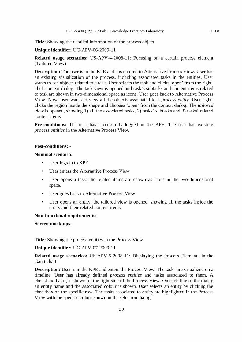
IST-27490 (IP): KP-Lab – Knowledge Practices Laboratory D II.8
42
Title: Showing the detailed information of the process object
Unique identifier: UC-APV-06-2009-11Related usage scenarios: US-APV-4-2008-11: Focusing on a certain process element(Tailored View)Description: The user is in the KPE and has entered to Alternative Process View. User hasan existing visualization of the process, including associated tasks in the entities. Userwants to see objects related to a task. User selects the task and clicks ‘open’ from the right-click context dialog. The task view is opened and task’s subtasks and content items relatedto task are shown in two-dimensional space as icons. User goes back to Alternative ProcessView. Now, user wants to view all the objects associated to a process entity. User right-clicks the region inside the shape and chooses ‘open’ from the context dialog. The tailoredview is opened, showing 1) all the associated tasks, 2) tasks’ subtasks and 3) tasks’ relatedcontent items.
Pre-conditions: The user has successfully logged in the KPE. The user has existingprocess entities in the Alternative Process View.
Post-conditions: -
Nominal scenario:
• User logs in to KPE.
• User enters the Alternative Process View
• User opens a task: the related items are shown as icons in the two-dimensionalspace.
• User goes back to Alternative Process View
• User opens an entity: the tailored view is opened, showing all the tasks inside theentity and their related content items.
Non-functional requirements:Screen mock-ups:
Title: Showing the process entities in the Process View
Unique identifier: UC-APV-07-2009-11Related usage scenarios: US-APV-5-2008-11: Displaying the Process Elements in theGantt chartDescription: User is in the KPE and enters the Process View. The tasks are visualized on atimeline. User has already defined process entities and tasks associated to them. Acheckbox dialog is shown on the right side of the Process View. On each line of the dialogan entity name and the associated colour is shown. User selects an entity by clicking thecheckbox on the specific row. The tasks associated to entity are highlighted in the ProcessView with the specific colour shown in the selection dialog.

IST-27490 (IP): KP-Lab – Knowledge Practices Laboratory D II.8
43
Pre-conditions: The user has successfully logged in the KPE. The user has existingprocess entities in the Alternative Process View with tasks associated to them.
Post-conditions: -
Nominal scenario:
• User logs in to KPE.
• User enters the Process View
• User selects an entity from the dialog on the right-side tab
• The tasks associated to the entity are highlighted with the specific colour shown inthe checkbox dialog.
Non-functional requirements:
Screen mock-ups:
Title: Showing the process entities in the Content Item View.Unique identifier: UC-APV-08-2009-11
Related usage scenarios: US-APV-3-2008-11: Using Alternative Process View elementsin the Content View
Description: User is in the KPE and enters the Content Item View. The entities defined inthe Alternative Process View. User has already defined process entities and tasksassociated to them. The process entities are presented with the specific icon type. The tasksassociated to them are visualized with a relationship link (an arrow) pointing from task tothe entity. User is able to open a process entity by double-clicking the icon or choosing‘open’ from the context dialog (see use case UC-APV-06-2009-11).
Pre-conditions: The user has successfully logged in the KPE. The user has existingprocess entities and tasks associated to them.
Post-conditions: -Nominal scenario:
• User logs in to KPE.
• User defines / has defined process entities and associated tasks to them in theAlternative Process View.
• User opens the Content Item View.
• Process entities are shown as icons in the two dimensional space, associated tasksare related to them with the relationship links (arrows).
Non-functional requirements:Screen mock-ups:

IST-27490 (IP): KP-Lab – Knowledge Practices Laboratory D II.8
44
3 Technical design
3.1 Software architecture
Figure 1 presents the overall architecture of the Alternative Process View. The userinterface and the visualization functionalities of the Alternative Process View areimplemented in the Tool layer. For storing and fetching process entities and tasks, theKnowledge Process Service is utilized. Knowledge Process Service stores the data insideSWKM, the semantic data repository.
Figure 6: Alternative Process View and the overall architecture

IST-27490 (IP): KP-Lab – Knowledge Practices Laboratory D II.8
45
3.2 GUI
3.2.1 Screen Design
In the figure 2, an empty Alternative Process View is presented: user has entered the viewand has not defined any elements to it.
Figure 7: Empty Alternative Process View
The tasks defined in the shared space are located in the no-man’s land, at the bottom of thescreen. Currently, there is only one task (‘task6’).In the figure 3, user has uploaded a background image to visualize the process to bepresented. The background image presents a cyclic model of progressive inquiry. On thetop of the picture, user can add shapes that define the process entities for the model: withthe process entities user defines formally the borders of an activity from the picture. If theuser doesn’t want to cover the original picture, she can use transparent process entities.
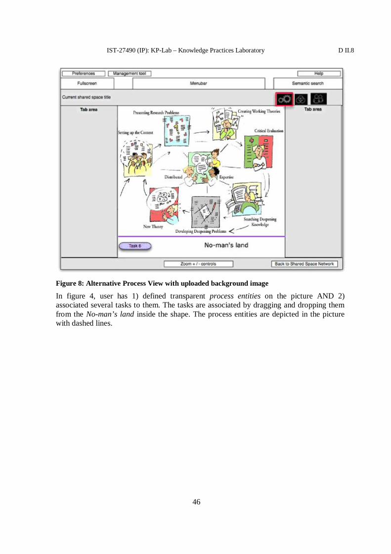
IST-27490 (IP): KP-Lab – Knowledge Practices Laboratory D II.8
46
Figure 8: Alternative Process View with uploaded background image
In figure 4, user has 1) defined transparent process entities on the picture AND 2)associated several tasks to them. The tasks are associated by dragging and dropping themfrom the No-man’s land inside the shape. The process entities are depicted in the picturewith dashed lines.

IST-27490 (IP): KP-Lab – Knowledge Practices Laboratory D II.8
47
Figure 9: Process entities with associated tasks on the picture
3.2.2 Services used
The Alternative Process View utilizes Knowledge Process Service for storing and fetchingthe process entities, links associating the process entities and tasks.
3.2.3 Relation to Ontologies
The process model defined in the Alternative Process View is stored in the SWKMrepository. The data and their relations are modeled in RDF. All the actions taken duringthe definition of the process are logged for further semantic analysis of the knowledgeevolution.
3.3 Front end services
Alternative Process View utilizes the Knowledge Process Service for storing the task andprocess entity information.
3.4 Collaboration with other tools
The Alternative Process View data is synchronized with the Process View and the ContentItem View. In the Alternative Process View, the association between a task and a processelement is created by dragging a task inside a process element. In the Content Item View,

IST-27490 (IP): KP-Lab – Knowledge Practices Laboratory D II.8
48
the association is shown with a link between the items. In the Process View, theassociation is shown with a colour highlighting.
References
[1] D2.4 Driving Objectives and High-level Requirements for KP-Lab Technologies(revised version). http://www.kp-lab.org/intranet/work-packages/wp2/result/D2.4_Resubmission_290809.doc
[2] D3.2 A comprehensive research strategy (an updated and revised version for years4 and 5). http://www.kp-lab.org/intranet/work-packages/wp1/submission-to-commission-23-9.2009/D3.2-Rev-Research-Strategy_September_submitted.doc
[3] Alternative Process View System Usage Scenarios http://www.kp-lab.org/intranet/design-teams/wk-process-management-and-analysis/alternative-process-views/wk3-apv_systemusagescenarios02_TUK-FHOOE.doc/view?searchterm=alternative%20process%20view

IST-27490 (IP): KP-Lab – Knowledge Practices Laboratory D II.8
49
Annex 2. Clipboard tool specifications

27490
KP-LAB
Knowledge Practices Laboratory
Integrated Project
Information Society Technologies
M44 software specification of end-user applications –<Clipboard Tool in KP Environment>
Due date of deliverable: … ..Actual submission date:
Start date of project: 1.2.2006 Duration: 60 Months
Organisation name of lead contractor for this deliverable:
Revision [1.0]
Project co-funded by the European Commission within the Sixth Framework Programme(2002-2006)Dissemination LevelPU Public PUPP Restricted to other programme participants (including the CommissionRE Restricted to a group specified by the consortium (including the
CO Confidential, only for members of the consortium (including theCommission Services)

IST-27490 (IP): KP-Lab – Knowledge Practices Laboratory D II.8
51
Contributors:Name Partner organisation EmailUH Minna Lakkala
Sami [email protected] ,[email protected]
UU Crina .Damsa [email protected] Markus Holi
Hannu MarkkanenEini SaarivesiMerja BautersPatrick Auderau
[email protected]@[email protected]@[email protected]
TUK Jan ParalicJozef Wagner
[email protected]@gmail.com
DIBE Marine ScapollaAngela Locoro
[email protected],[email protected]
FH-OÖ Christoph RichterEva Zoeserl
[email protected] ,[email protected]
Version history:Version Date Author(s) Description0.1 21.9.09 Marina Scapolla First draft0.1 21.9.09 Eini Saarivesi User Requirements and MockUps
21.9.09 Merja Bauters User Requirements0.2 26.10.09 Angela Locoro Changes to the front end services description
28.10.09 Marina Scapolla Modifications to the technical part0.3 30.10.09 Patrick Ausderau Contributions on how to manage the copy of
objects and interactions with the GUI level.0.31 02.11.09 Merja Bauters User requirements Updates
Angela Locoro0.32 04.11.09Marina Scapolla
Modifications to the technical part given thesuggestions from Patrick
0.4 16.11.09 Merja Bauters andSaarivesi
New SUS added
1.0 18.11.09 Marina Scapolla andAngela Locoro
Final revision

IST-27490 (IP): KP-Lab – Knowledge Practices Laboratory D II.8
52
Table of Contents
Table of Contents..................................................................................................................521 Introduction...................................................................................................................53
1.1 Purpose..................................................................................................................531.2 Scope of the software ............................................................................................531.3 Roadmap of the tool ..............................................................................................53
2 User requirements .........................................................................................................532.1 Relationship with KP-Lab research studies ............................................................532.2 Driving Objectives and High-Level Requirements .................................................542.3 System User Scenarios ..........................................................................................542.4 Use cases...............................................................................................................54
2.4.1 Actors................................................................................................................542.4.2 Index of Use cases .............................................................................................542.4.3 Detailed Use Cases ............................................................................................54
3 Technical design ...........................................................................................................593.1 Software architecture.............................................................................................593.2 Front end services..................................................................................................59
3.2.1 Web Service Interface Description.....................................................................593.2.1.1 Methods provided ......................................................................................59
3.2.2 Analysis of metadata and properties of the items created using templates...........623.2.2.1 SharedSpace............................................................................................... 623.2.2.2 Tasks .........................................................................................................623.2.2.3 Vocabularies ..............................................................................................643.2.2.4 Content Items.............................................................................................64
3.3 Collaboration with other tools................................................................................653.3.1 Information to be logged into the HPA repository..............................................65
4 References.....................................................................................................................66

IST-27490 (IP): KP-Lab – Knowledge Practices Laboratory D II.8
53
1 Introduction
1.1 Purpose
This document describes the functionality of the Clipboard Tool facility inside the KPEnvironment (KPE). It supports the operations of copying and pasting different items in theKPE.The document contains use cases, mock-up screens, data model and describes the webservice that will be developed for this functionality.
1.2 Scope of the software
This software allows creating new items in the KPE starting from existing ones.
These items can be:• Shared Spaces• Tasks• Vocabularies• Content Items
o Uploadable File, Web link, Note, Sketch, Scorm/IMS file, Wiki pages
1.3 Roadmap of the tool
This is the first version of the tool.
M44 SpecificationsM46 Prototype ReleaseM48 Production release
2 User requirements
2.1 Relationship with KP-Lab research studies
The pedagogical studies related to the KPE Clipboard Tool functionality are:
Case 1: Trialogical work in higher education; creation and use of knowledge objects inknowledge creation practices
Case 2: Knowledge creation practices in customer projects in higher educationCase 3: Conceptual modelling in Design Projects
Case 4: Producing document management solutions and practices for distributed worksettings – Perspectives of KPE usage in two work organizations
(See details in the D 3.2. Revised Research Strategy)

IST-27490 (IP): KP-Lab – Knowledge Practices Laboratory D II.8
54
2.2 Driving Objectives and High-Level Requirements
The Driving objective (DO) relevant for the tool is:
DO 3: Users are provided with support for the re-use of shared artefacts andstructuresThe high-level requirement (HLR) relevant for the tool is:HLR3.1 Users can re-use process structures and artefacts.
The DO and HLR are specified in Deliverable 2.4 Resubmitted (1, pp 28-29).
2.3 System User Scenarios
These specifications are based on two different system usage scenarios presented in the“WK1: Shared Space and Common Tools System usage scenarios for the Clipboard Tool”document:
1. US-Clipboard-1-2009-11 Copying a Shared Space and pasting it as a new SharedSpace
2. US-Clipboard-2-2009-11 Copying an element or elements (e.g. Content Items,vocabularies) and pasting them in another Shared Space.
2.4 Use cases
This section presents the two relevant use cases of the tool.
2.4.1 Actors
KPE users
2.4.2 Index of Use cases
1. UC-Clipboard-1-2009-11 Copying and pasting a Shared Space2. UC-Clipboard-2-2009-11 Copying and pasting elements from a Shared Space to
another.
2.4.3 Detailed Use Cases
1)
Title: Copying and pasting a Shared Space
Unique identifier: UC-Clipboard-1-2009-11
Related System Usage Scenarios: US-Clipboard-1-2009-11
1 D2.4 Driving Objectives and High-level Requirements for KP-Lab Technologies, version 0.4.http://www.kp-lab.org/intranet/work-packages/wp2/deliverable-2-4-driving-objectives-and-high-level-requirements-for-kp-lab-technologies-m32/Deliverable24-fourth-draft-DK-CR.doc/view

IST-27490 (IP): KP-Lab – Knowledge Practices Laboratory D II.8
55
Actors: KPE users who have right to create Shared Spaces
Description: The user wants to make a copy of a Shared Space s/he used before.
Pre-conditions: The user has entered the Shared Space Network.
Post-conditions: A new Shared Space is created. Details about its properties are in theTechnical Design Section. The action is logged in the HPA archive. Pasting a SharedSpace implies making a copy also of Tasks, Links between tasks (if tasks have links toother objects they will be ignored), Vocabularies and Tools.
Nominal scenario:1. The user has logged into the KPE, is in the Network View and has rights to create a
Shared Space.2. The user selects her/his Shared Space s/he wants to copy and by the top edit menu or
the right click menu, or by using shortcuts (Ctrl+C) chooses ”Copy”.3. The user navigates to the place in the Network View where s/he wants to paste the
Shared Space and selects “Paste” right clicking on the background, or from the topmenu.
4. A pop-up is displayed where the user can define the title, description and starting datefor the tasks of the new Shared Space. The user fills a unique title and optionally anew start date for tasks and a new description, and click OK.
5. The user receives a message confirming that the Shared Space was successfullycreated.
Screen mock-ups:
Mock-ups of general functions of copying and pasting are reported in the section thatdetails the use case UC-Clipboard-2-2009-11.
The image in Figure 1 displays the pop-up form that is presented to the user to fill beforethe actual pasting will occur. The user can define the title, modify the description and ifs/he wishes change the starting date of the tasks. The system will check if the title providedby the user is unique, i.e., that it is not already in use by some other Shared Space. If thiswould happen the system advises the users to change the title by stating in the red advicestyle “The title you suggest is already in use, please set another title”.

IST-27490 (IP): KP-Lab – Knowledge Practices Laboratory D II.8
56
Figure 1 – Pasting a Shared Space.
2)
Title: Copying and pasting elements from a Shared Space to another
Unique identifier: UC-Clipboard-2-2009-11
Related System Usage Scenarios: US-Clipboard-2-2009-11
Actors: Users who are allowed to add items in the source and the destination SharedSpaces
Description: The user wants to reuse his/her items again in another Shared Space. Theuser opens the Shared Space from where s/he wants to copy the items and selects them.Then the user navigates back to the Network View and finds the Shared Space into whichs/he wants to paste the items. The user goes into the Shared Space and pastes them. A lockicon appears on top of the to be pasted Content Items. In addition, a notice appears on theContent View. The notice states that “The process may take a while”, since the user copiedand pasted many Content Items.The items selected to be copied can be of type: Wiki, Uploadable File, Web link, Note,Sketch, Scorm/IMS file, Wiki page, Task, Vocabulary.

IST-27490 (IP): KP-Lab – Knowledge Practices Laboratory D II.8
57
Pre-conditions: The user has entered a Shared Space and his/her role allows adding items.
Post-conditions: New items are created, the action is logged in the HPA archive.
Nominal scenario:1. User has logged into the KPE and navigates from the Network View into the Shared
Space s/he wants to copy the items from.2. The user selects the items to be copied.3. The user can copy them from the “Edit menu”, the right click menu or by using
shortcuts (Ctrl+C) (see Fig. 2). A notice is displayed stating the copying wassuccessful.
4. The user moves to a different Shared Space.5. The user selects “Paste” from the Edit menu (see Fig. 3), the right click menu or by
using shortcuts (Ctrl+V).6. A lock icon and notice is displayed. The notice states: “The process may take a while”
The new items are created and the user sees them in a diagonally overlapping pile.
Screen mock-ups:The picture in Figure 2 presents how the copying and pasting occurs and how these optionsare displayed to the user.
Figure 2. Copying and pasting options

IST-27490 (IP): KP-Lab – Knowledge Practices Laboratory D II.8
58
Figure 3 and 4 show the process of copying and pasting item(s) or a Shared Space. Thesystem indicates that something is happening, i.e., displaying the lock icon on the item.The item should be placed to the place in the Content View (or Network View in the caseof Shared Space) where the users placed the cursor to place the item. If the user is usingthe menu to paste, then the item(s) is positioned in the same way as when creating a newitem.
Figure 3. Copying items

IST-27490 (IP): KP-Lab – Knowledge Practices Laboratory D II.8
59
Figure 4 Pasting process
3 Technical design
3.1 Software architecture
The overall KPE architecture documentation is available in the project Plone at the URLhttp://www.kp-lab.org/intranet/work-packages/wp6/result/dii-8-m46-specification-of-end-user-applications/kpe-architecture/folder_listing
3.2 Front end services
The Clipboard Tool Service will be implemented as a web service. It may use either thePersistence API or the KMS Request Engine to communicate with the KnowledgeRepository. The data stored on the Content Repository will be accessed via CIS Service(Content Item Web Service).
3.2.1 Web Service Interface Description
3.2.1.1 Methods provided
SharedSpacecopySSP(StringSSPURI,newTitle,newDescription,newStartDate,creatorURI)

IST-27490 (IP): KP-Lab – Knowledge Practices Laboratory D II.8
60
This is the method for copying a Shared Space (see section 3.3.2.1 for details). The SharedSpace creator is the user who does the copy. A "shift date" feature for the task whencopying the Shared Space will be provided (e.g. I have a Shared Space for the course I holdin 2009 and I want to copy it for 2010, then I provide a new "start" date, and the servicetakes care of using that date for the first task starting date and calculates the durations of allthe others tasks based on that).
input parameters:
Name Value type Description
SSPURI String the URI of the SSP to be copied
newTitle String The title for the new SSP
newDescription String The description for the new SSP
newStartDate Date start date of the earliest task of the new SharedSpace
creatorURI String the URI of the user who does the copy and willbecome the creator of the new Shared Space
output parameters:
Value type Description
SharedSpace The new SSP just created from the copy
String copy (ObjectOfActivity objectToCopy, String destinationURI, StringcreatorURI)
Method for copying a single object.
input parameters:
Name Value type Description
ObjectToCopy ObjectOfActivity The wrapper of the Object to be copied
destinationURI String The URI of the destination SSP
creatorURI String the URI of the user who does the copy and willbecome the creator of the new object
output parameter:
Value type Description
String the URI of the new object just copied
The object will be copied to the destination SSP selected by the user. The creator of the newobject is the user who does the copy. A new URI will be created of the same type of the

IST-27490 (IP): KP-Lab – Knowledge Practices Laboratory D II.8
61
original URI, and selected properties for that type will be copied. The method returns theURI of the new object. The original type will be assigned to the new object.
The method copy is complex and consists of several operations:
• Based on the object type a different selection of properties and different copyprocedures will be implemented (see details of properties and metadata for eachdifferent type in section 3.3.2).
• For any object tagged with Semantic Tags, the service will search the tagging termsin every vocabulary of the destination Shared Space (matching the PrefLabel andAltLabel fields). If a term does not exist, the term is added to the free tagsvocabulary. The new URI is assigned to the hasSemanticTag property of the newobject.
Uploadable Content Items (as the Notes) will have versions in the KPE M46-48; for themoment the last version of the item will be copied. When versioning will be used themethod will be adjusted in order to take care of which version/versions of the item must becopied.
String[] copyMultipleItems (OOA[] objectsToCopy, String destinationURI, StringcreatorURI)
Same method as above, but usable when the user selects multiple items to copy. Theseitems can be of different types. The creator of the new objects is the user who does thecopy. The method will copy relationship/hierarchical links if both start and end nodes thatparticipate in the relation are selected for the copy, as well as the link itself.
input parameters:
Name Value type Description
ObjectsToCopy ObjectOfActivity[] The wrapper of the Objects to be copied
destinationURI String The URI of the destination SSP
creatorURI String the URI of the user who do the copy and willbecome the creator of the new object
output parameter:
Value type Description
String[] the URIs of the new objects just copied in the same order as they wererequested

IST-27490 (IP): KP-Lab – Knowledge Practices Laboratory D II.8
62
3.2.2 Analysis of metadata and properties of the items created usingtemplates
Here below a list of the properties that will be set for each type of object at the moment ofcreating the new object. Notes beside the “Y” choice are present when the value of theproperty is not copied from the source object but is set to a new value.
3.2.2.1 SharedSpaceProperty Copied? Y/NbelongsToSharedSpace Y
Property must be set to the default“RootSpaceURI”
dc_alternative N dc_created Y
The date is set to the date of copy dc_creator Y
The creator is the user who does the copy dc_description Y
The new description is given as a parameter dc_modified N dc_title Y
The new title is given as a parameter employsOntology Y hasCommentAnnotation N hasOutboundRelationship N hasSemanticTag N
hasStatus N isProtectedTo N refersTo N
A Shared Space can have tasks and they will come along (see section 3.3.2.2 for details).Links between tasks will be copied. If tasks have links to other objects they will be ignored.A Shared Space can have vocabularies, they will be copied when copying the Shared Space(see section 3.3.2.3 for details).A Shared Space can have tools and these tools must be associated also to the copied SharedSpace. This association implies setting the following properties for each tool:
Property Copied? Y/N
belongsToSharedSpace Y dc_created Y the new date is the date of copy dc_creator Y the new creator is the user who does the copy dc_description Y dc_modified N dc_title Y manifestURI Y
3.2.2.2 TasksTo copy Tasks we must consider three different cases:

IST-27490 (IP): KP-Lab – Knowledge Practices Laboratory D II.8
63
1. When Tasks are copied as a consequence of copying a Shared Space: subTask andtaskPrerequisites are copied, other items related to the tasks are not copied;
2. When a specific Task is selected by the user inside a Shared Space to be copied: thesubTask and taskPrerequisites are not copied;
3. When multiple Tasks are selected to be copied then also relationship/hierarchicallinks, properties such as subTask, hasContentItem orhasOutboundRelationship can be copied too if the user has selected them for copy.
Property Copied? Y/NassignedMember N endTime Y
According to newStartDate parameter this valuewill be shifted properly
hasContentItem NUnless link to the Content Item and The contentitself are selected for copy
hasContentItemOrganizer N hasMilestone N startTime Y
According to newStartDate parameter this valuewill be modified properly
subTask YIn case subTasks are selected for copy
taskIndex YThis property is used for ordering purposes andmust be adjusted on the basis of tasks copied
taskPrerequisites YThis property describes relations between task,example. The next task cannot start …
taskStatus N belongsToSharedSpace Y
This property must be set to the properdestination Shared Space
dc_alternative N dc_created Y
The date is the date of copy dc_creator Y
The creator is the user who does the copy dc_description Y dc_modified N dc_title Y hasCommentAnnotation N hasOutboundRelationship Y
Only in case subtasks will come along with thecopy
hasSemanticTag Y hasStatus N isProtectedTo N refersTo N

IST-27490 (IP): KP-Lab – Knowledge Practices Laboratory D II.8
64
3.2.2.3 VocabulariesProperty Copied? Y/N vocabularyURI Y
The new vocabulary will have a new URI hasTopConcept Y
The new top concepts URIs will be associated resource_Description Y belongsToSharedSpace Y
This property will be created to link the SSPwhere the object is copied
dc_created YThe date is the date of copy
dc_creator YThe creator is the user who does the copy
resource_Title Y
A vocabulary has concepts, they will be copied in the vocabulary copy.Property Copied? Y/N conceptURI Y
The new concept will have a new URI inScheme Y
The new concept will be associated with newvocabulary URI
prefLabel Y altLabel Y broader Y
The new concept URIs will be associated narrower Y
The new concept URIs will be associated belongsToSharedSpace Y
This property will be created to link the SSp wherethe object is copied
dc_created YThe date is the date of copy
dc_creator YThe creator is the user who does the copy
resource_Title Y
3.2.2.4 Content ItemsUploadable File (UploadableContentItem)Web link (ExternalContentItem)NoteSketchScorm/IMS fileWiki page
Property Copied? Y/N contentItemURI Y
The new content item will have a new URI contentURI Y
A new contentURI will be created for each

IST-27490 (IP): KP-Lab – Knowledge Practices Laboratory D II.8
65
physical file in the content repository. For WebLinks the property will be copied as it is
dc_format Y dc_hasVersion N belongsToSharedSpace Y
This property will be created to link the SSPwhere the object is copied
dc_alternative N dc_created Y
The date is the date of copy dc_creator Y
The creator is the user who does the copy dc_description Y dc_modified N dc_title Y hasCommentAnnotation N hasOutboundRelationship Y
Only if the links and the objects related to the oneto be copied are also selected for copy
hasSemanticTag Y hasStatus N isProtectedTo N refersTo N
3.3 Collaboration with other tools
3.3.1 Information to be logged into the HPA repository
According to HPA official specification (3) all the actions of creating new items will belogged in the HPA, with the addition, in custom property fields, of a property with key“copied” and value the URI of the original object. The log will be implemented at KPE GUIlevel.
The table above reports as an example the logging record related to the copy of a task.
ID Time SubjectID
SubjectType
ObjectID
ObjectType
Action Comment Properties CustomData
Key value
User Name
Surname
Title Tasktitle
1 Date
time
Userdoingtheaction
e.g.
teacher
ObjectURI
Task creation
SSPID Destination
SSP URI

IST-27490 (IP): KP-Lab – Knowledge Practices Laboratory D II.8
66
copied URI oftheoriginalobject
4 References1. Dow4.1.1 document: http://www.kp-lab.org/intranet/work-
packages/wp1/description-of-work/dow4-1-1/?searchterm=DoW4.12. HPA Official page: http://kplab.tuke.sk/trac/wiki/hpa
3. HPA Specification document: http://www.kp-lab.org/intranet/design-teams/wk-shared-space-and-common-tools/awareness/participation-and-history-based-awareness/history_awareness_technical_v02.doc
4. CIS Manual for CIS services: http://trac.kp-lab.org/browser/wp6/ContentItemService/branches/M44/CIS%20Manual.doc

IST-27490 (IP): KP-Lab – Knowledge Practices Laboratory D II.8
67
Annex 3. Data Export tool specifications

27490
KP-LAB
Knowledge Practices Laboratory
Integrated Project
Information Society Technologies
DII.8 M42 software specification of end-user applications –Data export tool
Due date of deliverable:Actual submission date:
Start date of project: 1.2.2006 Duration: 60 Months
Organisation name of lead contractor for this deliverable: Metropolia
Revision [1.0]
Project co-funded by the European Commission within the Sixth Framework Programme(2002-2006)Dissemination LevelPU Public PU
PP Restricted to other programme participants (including the CommissionServices)
RE Restricted to a group specified by the consortium (including theCommission Services)
CO Confidential, only for members of the consortium (including theCommission Services)

IST-27490 (IP): KP-Lab – Knowledge Practices Laboratory D II.8
69
Merja Bauters Metropolia [email protected] Richter FH OO [email protected] Zoeserl FH OO [email protected] Marina Scapolla DIBE [email protected] Locoro DIBE [email protected] Wagner TUK [email protected] Lakkala UH [email protected]
Contributors:
Crina Damsa UU [email protected](s): Anna Marina ScapollaPartner(s): DIBEWork Package: WPIINature of thedeliverable:
Version historyVersion Date Author(s) Description1.0 20.11.2009 A. M. Scapolla,
A.LocoroFirst release, the document has been producedupdating the specifications of the M36 tool
1.1 18.12.2009 Jozef Wagner Changes related to the movement of services from theHPA into the KAS (Knowledge AnalysisServices).

IST-27490 (IP): KP-Lab – Knowledge Practices Laboratory D II.8
70
Table of Contents
Table of Contents..................................................................................................................701 Introduction...................................................................................................................71
1.1 Purpose..................................................................................................................711.2 Scope of the software ............................................................................................711.3 Roadmap of the tool ..............................................................................................711.4 What is new in this version? ..................................................................................711.5 Definitions.............................................................................................................72
2 User requirements .........................................................................................................732.1 KP-Lab empirical research ....................................................................................732.2 Driving Objectives and High-Level Requirements .................................................732.3 System usage scenarios..........................................................................................742.4 Use cases...............................................................................................................74
2.4.1 Actors............................................................................................................742.4.2 Detailed Use Case..........................................................................................74
2.4.2.1 Shared Space Items’ Analysis Tab .............................................................752.4.2.2 User Action Log Tab..................................................................................79
3 Technical design ...........................................................................................................813.1 Software architecture.............................................................................................81
3.1.1 Services Used ................................................................................................823.1.2 Relation to Ontologies ...................................................................................82
3.2 Collaboration with other tools................................................................................824 References.....................................................................................................................82

IST-27490 (IP): KP-Lab – Knowledge Practices Laboratory D II.8
71
1 Introduction
1.1 Purpose
This document contains a detailed description of improvements and new functionality ofthe M42 release of the Data Export tool..
1.2 Scope of the software
Data export tool allows researchers and teachers to extract summary tables of useractivities from the KPE for on-line investigation, and to export them for elaborations withstatistical analysis packages. It gathers data about activities taking place in the KPE andextracts data from the Awareness Repository, the users database and the KnowledgeRepository.This document specifies the improvements and the extensions that the M36 tool has had onthe basis of the feedback from tests of the M36 tool and of the user requirements.
1.3 Roadmap of the tool
The implemented and planned iterations of the Data Export Tool are as follows:
• Iteration 1 (M12-M24): Feasibility study and prototyping. Release v1.0• Iteration 2 (M25-M36): Improvements and extensions of the tool functionalities.
o Milestones:• M32 Specifications, M33 Prototype v2.0• M33 Refined Specifications, M36 Release v2.1.
• Iteration 3 (M37-M42): Extensions of functionalities according to the users’priorities on the requirements collected by the partners and integration of graphicalview for “Social Networks Analysis”.
o Milestones: M42 Release v3.0 - This release provides extendedfunctionality, according to the users’ requirements and the tests done on theM36 release, improvements of GUIs design and it will add graphical viewsto the “Social Networks Analysis” function.
• M48 release: this is part of the major production release of KPE. The tool will befurther maintained and improved in order to fulfil the requirements of exportingadditional data. It will include also the possibility of exporting data in a formatcompatible with Reference Model.
This document describes specifications of iteration 3.
1.4 What is new in this version?
This version of the tool presents both improvements to the M36 release and a newfunctionality related to the graphical views of Social Networks .

IST-27490 (IP): KP-Lab – Knowledge Practices Laboratory D II.8
72
The improvements origin from the observations of the partners after testing the M36release (see the user requirements section for references to the documents produced bypartners in charge of testing and evaluation of the M36 release).Main improvements cover:
• Overall design of GUI• Usability of the tool• Optimization of queries and a consequent better response time• Naming issues• Formatting the exported data• Adding new types of data. .
1.5 Definitions
Analysis of items by user: this analysis results in a table reporting the SSp users (one perrow) and the numbers of items created by each user. The items are counted and grouped byobject type (e.g. Files, Wikis, Notes, Comments, Links, SCORMs, Tasks and so on).
Content items analysis –The process of searching all the content items of a shared space,and counting the actions they have been subjected to. This analysis results in a table whereeach row represents a Content Item and its properties: creator name, title, type, creationdate and time, number of comment threads, of comments, of links - inbound and outbound,of tags, of responsible persons.
Tasks analysis - this analysis results in a table where each row represents a Task and itsproperties: Title, Creator, number of SubTasks, Subtask Title, Parent Task Title, Level ofthe task, Creation date and time, Start Date, End Date, number of Inbound Links, ofOutbound Links, of Semantic Tags, of Comments threads, of Sub Comments, total numberof Comments, of Contents, of responsible persons and of Milestone
Social network analysis –The process of searching the interrelationships that have beenestablished among the users of a shared space in operating on other users’ contents. Theoutput of this process is a square matrix summarizing the numbers of actions carried out.
User action log analysis – The process of searching the action log and reporting::• a table summarizing the number of actions per user and per type (create, modify,
delete,...) with the possibility to filter a specific time interval.• a list of the actions carried out in a certain time interval by one specific user or by all
users.
History/Participation Awareness (HPA) - HPA is a repository of events representingactivities or changes performed by users of various end-user tools in KP-environment.Logs of these events provide source data for analysis and identification of new knowledgethat can be used for analysis and improvement of on-going activities as well as foradaptation of the graphical user interface or for personalization

IST-27490 (IP): KP-Lab – Knowledge Practices Laboratory D II.8
73
Knowledge Analysis Services (KAS) - KAS provides the necessary middlewarefunctionality for KPE end user tools which require a rich set of services for selecting andaggregating proper data from underlying log repositories, as well as for defining externalevents, for commenting and semantically annotating all types of events, and for patternsdescription and identification.
Knowledge practices environment (KPE) – KPE is the application that is used to log into/out of the KP-Lab system, to use shared spaces with the integrated tools, and to launchother loosely integrated KP-Lab tools, such as the Activity System Design Tool. The KPEcovers all the (end-user) tools under development by Working Knots 1-5 (cp. DoW3.1, p.27).Shared space (SSp) – SSp is a virtual area that may contain tools and objects. An SSpmay have one or more members. The number of different SSps is practically unlimited.
Trialogical Learning Ontology (TLO) - The core domain ontology that providescommon semantics for applications and tools and defines concepts and notions oftrialogical learning.
2 User requirements
2.1 KP-Lab empirical research
The tool functionalities specified in this document will be used in the following KP-Labempirical research cases [4]:Case 1: Trialogical work in higher education; creation and use of knowledge objects inknowledge creation practicesCase 2: Knowledge creation practices in customer projects in higher education
Case 3: Conceptual modelling in Design ProjectsCase 4: Producing document management solutions and practices for distributed worksettings – Perspectives of KPE usage in two work organizationsThe development of the M42 version of the tool was driven mainly by the feedback ofusers after testing and evaluating the M36 release and their new requests. Three documentsare available in the project Plone:
Usability Report UU 03-2009 Expert EvaluationUsability Report UH 05-2009, Diagnostic EvaluationUsability Report FH-OOE-09 2009 Expert evaluation
2.2 Driving Objectives and High-Level Requirements
The Driving objectives (DO) relevant for the tool are the same listed in the D6.6 M33 toolspecifications.
IST-27490 (IP): KP-Lab – Knowledge Practices Laboratory D II.8
74
2.3 System usage scenarios
These specifications are based on the tool usage scenarios presented in (1):1. US-DataExport-1-2008-11: Retrieving data of user activity in a shared space2. US-DataExport-2-2008-11: Retrieving data of content items3. US-DataExport-3-2008-11: Retrieving data of tasks4. US-DataExport-4-2008-11: Social networks content item analysis and task analysis5. US-DataExport-5-2008-11: Retrieving "User Action Log" summary for analysis6. US-DataExport-6-2008-11: Retrieving "User Action Log" of detailed analysis of users
actions
2.4 Use cases
This section presents how the M42 data export tool can be used.
2.4.1 Actors
Users of the Knowledge Practices Environment tool (i.e. teachers, assistants, courseadministrator) who have entered a shared space.
2.4.2 Detailed Use Case
Description:The main steps in the usage of the tool are:
• The user enter a Shared Space and selects the “Open Data Export” from the “Tool”drop down menu of the upper menu.
• The Data Export tool home page opens in a new browser window and the userselects the type of analysis s/he wants.
• The system runs the data export application on the basis of the selection.
• The tool visualizes tables containing the results of the analysis and in case a “Socialnetwork analysis” has been chosen, a new tab is opened to visualize the graph ofthe network.
• The user can select all or specific columns of data for exporting them Excel format.
Pre-conditions:The user is within the Knowledge Practices Environment and has entered a shared space.
Post-conditions:The Data Export application opens a new browser window and the user can go on selectingthe type of analysis, running it, looking at results and exporting data.
1 “M36 System usage scenarios for the Data Export analysis tool http://www.kp-lab.org/intranet/design-teams/wk-shared-space-and-common-tools/data-export-for-analysis/System%20Usage%20ScenarioDataExport0_2.doc/view “

IST-27490 (IP): KP-Lab – Knowledge Practices Laboratory D II.8
75
Screen mock-ups:Figure 1 shows the Data Export home page where the user can start analysing SSP items.The home page presents two tabs. The Shared Space Items’ Analysis Tab and the UserAction Log Tab. Section 2.4.2.1 describes the Shared Space Items’ Analysis functionalityand the output resulting from this analysis, section 2.4.2.2 deals with the User Action LogTab.
Figure 1 – The Data Export home page
2.4.2.1 Shared Space Items’ Analysis Tab
Five different analyses are available. Once the user has made the choice, the request iscarried out and the analysis results are presented in a new tab named “Summary table”,This tab, when present, contains always the results of the last analysis done.
1) Analysis of items by user: this analysis results in a table reporting the SSp users(one per row) and the numbers of items created by each user. The items arecounted and grouped by object type (e.g. Files, Wikis, Notes, Comments, Links,SCORMs, Tasks and so on). ). The table is ordered by username. An example ofresults table is depicted in Figure 2, which contains also help for using the buttonsof data selection and data export in Excel format.
Click the submitbutton if you wantto run an analysis

IST-27490 (IP): KP-Lab – Knowledge Practices Laboratory D II.8
76
Figure 2 - Table of results for Analysis of items by user
2) Content items analysis: this analysis results in a table where each row represents aContent Item and its properties: creator name, title, type, creation date and time,number of comment threads, of comments, of links - inbound and outbound, of tags, ofresponsible persons (see Figure 3). The table is ordered by Item type and by Item title.Buttons for selecting columns and export data to Excel are the same for all the analysis.
Figure 3 – Table of results for Analysis on Content Items. In the figure some Creatorfields are null. This is due to inconsistencies in the Knowledge repository that should
be fixed by the last software release.
3) Task analysis: this analysis results in a table where each row represents a Task andits properties: Title, Creator, number of SubTasks, Sub Task Title, Parent Task Title,
Click the select button to select singlecolumn for exporting to Excel. The columnbecomes orange.
Click the Select All button if you want to select allthe columns to export them to Excel. All thecolumns will become orange
Click the Export to Excel button after you columnselection to download data in Excel format

IST-27490 (IP): KP-Lab – Knowledge Practices Laboratory D II.8
77
Level of the task, Creation date and time, Start Date, End Date, number of InboundLinks, of Outbound Links, of Semantic Tags, of Comments threads, of SubComments,total number of Comments, of Contents, of responsible persons and of Milestone ( seeFigure 4). ). The table is ordered by Task title and grouped by Task /SubTask.
Figure 4 – Table of results for Tasks Analysis.
4) Social Network analysis –comments on content items: this analysis results in asquare matrix where each row is relative to a creator of Content Items, and thecolumns report how many comments have been done by the SSP users on thecontent items created by the user,
5) Social Network analysis –comments on tasks: this analysis results in a squarematrix where each row is relative to a creator of Tasks, and the columns report howmany comments have been done by the SSP users on the task created by the user,
Social Network analysis show these tables in the “Summary table” tab, moreover a newtab, named Network Visualizer, is created. This tab contains a graphical presentation ofthe table. An example of a summary table resulting from Social Network Analysis isdepicted in Figure 5. The Social Network Visualization is depicted in Figure 6.

IST-27490 (IP): KP-Lab – Knowledge Practices Laboratory D II.8
78
Figure 5 – Table results for Social Network. As the matrix is very large (it contains all theSSP users) a horizontal scrolling has to be done to see
the analysis title and access Select All and Export to Excel buttons
The Network Visualizer depicts a graph where nodes are users and labelled linksrepresent the existing connections between users and how many comments have beendone. Pointing over the links a tooltip will come up with a description of who didcomments to whom and how many.
With the left Panel you can zoom the graph, change the nodes orientation, and customizethe links. Click the “Close Panel” button if you want the entire window for visualizing thegraph.. At the bottom of the left Panel there is a legend of symbols: bidirectional links areblack, unidirectional links are yellow, labelled links depicts the number of comments whilea number between parenthesis beside the user yellow name shows self comments (e.g.comments that a user did on its Content Items) if there are such comments.

IST-27490 (IP): KP-Lab – Knowledge Practices Laboratory D II.8
79
Figure 6– An example of the Network Visualizer GUI
2.4.2.2 User Action Log Tab
The User Action Log allows to query the SSP logs (HPA archives) and to retrieve theactions that have been done on objects belonging to the shared space. The user interfacerelative to this analysis is depicted in Figure 7.
There are two types of analysis:
1) Summary: this analysis results in a table where each row represents a SSP user and foreach type of action, the sum actions logged for that user are reported (Figure 8).
Figure 7 – The User Action Log Tag home
The calendar button to restrict therange dates of the logs analysis.
The Details analysis can beperformed on all SSP members(by default) or by selecting asingle SSP member from the list

IST-27490 (IP): KP-Lab – Knowledge Practices Laboratory D II.8
80
2) Details: this analysis results in a table where each row represents a single log record,an action performed by the user and logged into the awareness repository. The table iscronological ordered by date of logging. The Details analysis extracts by default all theSSP members’ actions. If you want to export only the ations of a single SSP member,you can select a single member before running the query (Figure 9).
For both analysis Start and End dates are by default the SSP creation date and the todaydate respectively. If a user wants to change (restrict) the date range he/she should use thecalendar button beside each date.
Figure 8 – The Summary analysis results of User Action Log

IST-27490 (IP): KP-Lab – Knowledge Practices Laboratory D II.8
81
Figure 9 – The Details analysis results of the User Action Log for all SSP members.
3 Technical design
3.1 Software architecture
The overall KPE architecture documentation is available in the project Plone at the URLhttp://www.kp-lab.org/intranet/work-packages/wp6/result/dii-8-m46-specification-of-end-user-applications/kpe-architecture/folder_listing .Data Export tool is designed as an independent Web Application, packaged in a WebArchive (WAR), with all its components (Apache POI - Java API To Access MicrosoftFormat Files to support CVS format and KME-RE-Client for communication with theKR). The creation and management of controls is delegated to proper Java classes(TagSupport classes).
The Network Visualization has been developed integrating the KapLab Data Visualizationsoftware (http://lab.kapit.fr/display/visualizer/Visualizer).The choice of this software has been preceded by the analysis of the available notcommercial tools for social networks visualization. The results of this study are available athttp://www.kp-lab.org/intranet/design-teams/wk-shared-space-and-common-tools/data-export-for-analysis/SNVizualisationTools.doc/view?searchterm=social%20networks

IST-27490 (IP): KP-Lab – Knowledge Practices Laboratory D II.8
82
3.1.1 Services Used
The tool queries the HPA repository through KAS Query service (2) and the Knowledgerepository through SWKM client library.
3.1.2 Relation to Ontologies
The tool is heavily dependent on the TLO and FOAF ontologies. The TLO ontologydefines the properties of the knowledge artefacts and the possible relationships amongthem. These artefacts and interrelationships are the objects of the data export tool’sanalysis processes. The FOAF ontology provides users’ properties.
3.2 Collaboration with other tools
The tool queries the HPA repository through KAS Query service and the KnowledgeRepository.
4 References1 “M36 System usage scenarios for the Data Export analysis tool http://www.kp-lab.org/intranet/design-teams/wk-shared-space-and-common-tools/data-export-for-analysis/System%20Usage%20ScenarioDataExport0_2.doc/view “1 D5.6 (Resubmitted with respect to review 3 report) - http://www.kp-lab.org/intranet/work-packages/wp5/result/deliverable-5.6/D5.6_update-after-3rdPrjReview_final.doc
3 Data Export M33 specificationshttp://www.kp-lab.org/intranet/work-packages/wp6/result/d6-6-m33-specification-of-end-user-applications/shared-space-and-common-tools/data-export-service-gui-dibe/D6.6_Data%20export%201.0.doc/view
4. D3.2 A comprehensive research strategy (an updated and revised version for years 4 and5). http://www.kp-lab.org/intranet/work-packages/wp1/submission-to-commission-23-9.2009/D3.2-Rev-Research-Strategy_September_submitted.doc
2 D5.6 (Resubmitted with respect to review 3 report) - http://www.kp-lab.org/intranet/work-packages/wp5/result/deliverable-5.6/D5.6_update-after-3rdPrjReview_final.doc

IST-27490 (IP): KP-Lab – Knowledge Practices Laboratory D II.8
83
Annex 4. Search tool specifications

27490
KP-LAB
Knowledge Practices Laboratory
Integrated Project
Information Society Technologies
DII.8 M46 specification of end-user applications –Search tool
Due date of deliverable: 30/11/2009Actual submission date:
Start date of project: 1.2.2006 Duration: 60 Months
Organisation name of lead contractor for this deliverable: Metropolia
Revision [1.0]
Project co-funded by the European Commission within the Sixth Framework Programme(2002-2006)Dissemination LevelPU Public PU
PP Restricted to other programme participants (including the CommissionServices)
RE Restricted to a group specified by the consortium (including theCommission Services)
CO Confidential, only for members of the consortium (including theCommission Services)

IST-27490 (IP): KP-Lab – Knowledge Practices Laboratory D II.8
85
Contributors:Markus Holi Metropolia [email protected] Markkanen Metropolia [email protected] Bauters Metropolia [email protected] Paralic TUK [email protected] Bednar TUK [email protected]šek Babi TUK [email protected]
Version historyVersion Date Author(s) Description0.1 22.11.2009 Markus Holi First draft of the specification

IST-27490 (IP): KP-Lab – Knowledge Practices Laboratory D II.8
86
Table of Contents
Table of Contents..................................................................................................................861 Introduction...................................................................................................................87
1.1 Purpose...................................................................................................................871.2 Scope of the software..............................................................................................871.3 Roadmap of the tool................................................................................................ 871.4 What is new in this version?....................................................................................871.5 Definitions ..............................................................................................................87
2 User requirements .........................................................................................................882.1 Relationship with KP-Lab research studies .............................................................882.2 Driving Objectives and High-Level Requirements ..................................................882.3 System usage scenarios ...........................................................................................882.4 Use cases ................................................................................................................89
2.4.1 Actors..............................................................................................................892.4.2 Use cases .........................................................................................................892.4.3 Detailed Use Cases ..........................................................................................89
3 Technical design ...........................................................................................................913.1 Software architecture ..............................................................................................913.2 GUI ........................................................................................................................92
3.2.1 Screen Design..................................................................................................923.2.2 Services Used ..................................................................................................933.2.3 Relation to Ontologies .....................................................................................93
3.3 Front-end services...................................................................................................933.3.1 Front-end Service Interfaces ............................................................................933.3.2 Used Platform services ....................................................................................933.3.3 Search-specific Data Persistence ......................................................................93
3.4 Collaboration with other tools .................................................................................934 References.....................................................................................................................94
IST-27490 (IP): KP-Lab – Knowledge Practices Laboratory D II.8
87
1 Introduction
1.1 Purpose
This document describes the functionality of the search tool. It consists of use cases, mock-up screens, data model, and describes the required KP-LAB services.
1.2 Scope of the software
The purpose of the software is to enable advanced faceted search based on the metadataand content of items.
1.3 Roadmap of the tool
During the DoW4 one stable release will be provided as follows:M48 stable release
• This release will add to the basic free-term and faceted semantic search features thepossibility to save search results
• SWKM services used: Query, Update.
• Milestones: M46: Specification, M48: Release.
1.4 What is new in this version?
This version adds the saving of search criteria along with search results.
1.5 Definitions
Free-term search –A search that is performed by using variations and extensions of stringmatching to satisfy the information need specified by the user. Usually the user writes thesearch terms freely in a text box. This search can be directed towards free-text content, i.e.full-text of the document or metadata fields that are defined as a free text, or towardssemantic content such as semantic tags.
Semantic search – A search which uses the structure of an ontology/ontologies andontology-based metadata to fulfil the query specified by the user. This means using therelations between items, the possible class-hierarchies etc. Usually the user selects thequery concepts from predefined options.
Faceted search – A search paradigm in which the searched items are indexed usingmultiple orthogonal dimensions or facets. The user can then search the items using thesemultiple facets simultaneously.

IST-27490 (IP): KP-Lab – Knowledge Practices Laboratory D II.8
88
Facet – A single dimension by which the user can search the item database. An example ofa facet is “Creation date” which provides search based on the creation dates of the searcheditems.
Search category – A single selectable value within a facet, for example “01.01.2007” as asearch category within the “Creation date” –facet. This selection will retrieve items that arecreated on the 1st of January, 2007.Knowledge practices environment (KPE) – KPE is the application that is used to log into/out of the KP-Lab system, to use shared spaces with the integrated tools, and to launchother loosely integrated KP-Lab tools, such as the Activity System Design Tool. The KPEcovers all the (end-user) tools under development by Working Knots 1-5 (cp. DoW3.1, p.27).
2 User requirements
2.1 Relationship with KP-Lab research studies
The tool functionalities specified in this document will be used in the following KP-Labempirical research cases [2]:Case 1: Trialogical work in higher education; creation and use of knowledge objects inknowledge creation practicesCase 2: Knowledge creation practices in customer projects in higher education
Case 4: Producing document management solutions and practices for distributed worksettings – Perspectives of KPE usage in two work organizations
2.2 Driving Objectives and High-Level Requirements
The Driving objectives (DO) relevant for the tool are:DO1: Provide a collaborative environment where users can work on shared artefactsDO 4: Users can describe the semantics of artefacts and their relationsDO 8: Enable users to plan, organize and manage tasks collaboratively
The high-level requirements (HLR) relevant for the tool are:HLR1.4 (DO 1) Users can search artefacts within and outside the shared environment using full text, metadata or
domain ontologies.HLR8.6 (DO 8) Users can search the content and metadata using full text or semantic metadata search for planning
and reflecting on activities.HLR4.1 (DO 4) Users can categorise, classify and cluster artefacts in different manners.
2.3 System usage scenarios
The tool specification is based on the following system usage scenario:1. SUS-Search-1-2009-11: Saving search criteria and results.

IST-27490 (IP): KP-Lab – Knowledge Practices Laboratory D II.8
89
2.4 Use cases
This section presents the use cases for the search tool.
2.4.1 Actors
User of the Knowledge Practices Environment
2.4.2 Use cases
1. UC-Search-01-2009-11: User saves search criteria and results.
2. UC-Search-02-2009-11: User opens the saved search object (content itemorganizer).
2.4.3 Detailed Use Cases
Title: User saves search criteria and results.
Unique identifier: UC-Search-01-2009-11
• Related usage scenarios: SUS-Search-1-2009-11: Saving search criteria and results.
• Actors: User of the Knowledge Practices Environment.
• Description: The user has entered a shared space, and selected ‘Search’ from theupper menu bar. The Search GUI has opened as a Flex-popup and the user hasperformed a search and received search results. The user decides to save the searchcriteria and the results to be used later. The user presses the save search buttonlocated at the top of the search result list. The search results and the criteria aresaved to SWKM as Content Item Organizer objects where the search results are thecontent items, and the search criteria as saved as the description of the organizer.The search tool informs the user by an alert box saying “search saved successfully”.
• Pre-conditions: The user has entered a shared space, and selected ‘Search’ from theupper menu bar. The Search GUI has opened as a Flex-popup and the user hasperformed a search and received search results.
• Post-conditions: The search results and the criteria are saved to SWKM as ContentItem Organizer objects where the search results are the content items, and thesearch criteria as saved as the description of the organizer. The search tool informsthe user by an alert box saying “search saved successfully”. The content itemorganizer is displayed in the content view of that shared space.
• Nominal scenario:o The user presses the save search button located at the top of the search
result list.o The search results and the criteria are saved to SWKM as Content Item
Organizer objects where the search results are the content items, and thesearch criteria as saved as the description of the organizer. The content itemorganizer belongs to the shared space from where the search tool was

IST-27490 (IP): KP-Lab – Knowledge Practices Laboratory D II.8
90
invoked. The content item organizer is displayed in the content view of thatshared space.
o The search tool informs the user by an alert box saying “search savedsuccessfully”.
• Non-functional requirements:o saving is reliable
• Screens: Figure 1 represents the saved search object (content item organizer) incontent view.
Figure 1: The saved search object as shown in content view.
Title: User opens the saved search object (content item organizer)
Unique identifier: UC-Search-02-2009-11
• Related usage scenarios: SUS-Search-1-2009-11: Saving search criteria and results.
• Actors: User of the Knowledge Practices Environment.
• Description: The user has entered the shared space in KPE where a saved searchexists as a content item organizer. The user double clicks the content itemorganizer. The saved search results are displayed as a list which is similar to the listof search results in search GUI. The search criteria are displayed at the top of thelist. By pressing the “Perform Search” button near the search criteria, the searchGUI is opened and a search is performed using the saved criteria.
• Pre-conditions: The user has entered the shared space in KPE where a saved searchexists as a content item organizer.
• Post-conditions:o The saved search results are displayed as a list which is similar to the list of
search results in search GUI.
o The search criteria are displayed at the top of the list.o By pressing the “Perform Search” button near the search criteria, the search
GUI is opened and a search is performed using the saved criteria.
• Nominal scenario:

IST-27490 (IP): KP-Lab – Knowledge Practices Laboratory D II.8
91
o The user double clicks a content item organizer which represents a savedsearch.
o The saved search results are displayed as a list which is similar to the list ofsearch results in search GUI. The search criteria are displayed at the top ofthe list.
o By pressing the “Perform Search” button near the search criteria, the searchGUI is opened and a search is performed using the saved criteria.
• Non-functional requirements:o The system should be able to perform each search within sensible time
limits.
• Screens: Figure 2 depicts an opened search object. The list of saved search result isdisplayed and the saved search results criteria on top. The user can perform asearch with the saved criteria by pressing “Search”.
Figure 2: The opened search object.
3 Technical design
3.1 Software architecture
The overall KPE architecture documentation is available in the project Plone at the URLhttp://www.kp-lab.org/intranet/work-packages/wp6/result/dii-8-m46-specification-of-end-user-applications/kpe-architecture/folder_listing .

IST-27490 (IP): KP-Lab – Knowledge Practices Laboratory D II.8
92
Figure 10 presents the overall architecture of the search functionality. The Search tool isone of the KPE Tools and it is invoked from the Knowledge Practices Environment GUI’supper menu bar. The Search GUI uses the Search Service for populating the facets, andretrieving the result items for searches specified by the user. The search service is based onthe Solr search engine (1). The properties relevant to search are indexed by the front-endservices. Indexing service is integrated with the Persistence API (P-API) and Gateways toContent Repositories (G2CR) to simplify maintenance of the index for tool developers. Inthe case that Persistence API is not used to manage objects of activities, it is possible toinvoke Indexing service directly using the Solr HTTP interface
The search service is called from GUI by the Data access services. The Data accessservices create the HTTP-request to the Search Service based on the user selections in theSearch GUI.The Search Service contains a function saveSearch which uses P-API to create the contentitem organizer object to be used as the object that represents the saved search.
Figure 10: Overall architecture of search.
3.2 GUI
3.2.1 Screen Design
Figures 1 and 2 present the screen design of the Search GUI.

IST-27490 (IP): KP-Lab – Knowledge Practices Laboratory D II.8
93
Figure 1 represents the saved search object (content item organizer) in content view.Figure 2 depicts an opened search object. The list of saved search result is displayed andthe saved search results criteria on top. The user can perform a search with the savedcriteria by pressing “Search”.
3.2.2 Services Used
• Search service - The main service supporting the search tool. It contains the saveSearchfunction which is used to save the search. It is called with 4 parameters:
o userURI of the savioro sharedSpaceURI where the search is savedo the search criteria as a stringo the list of item URIs of the search objects.
Based on these parameters the service creates a content item organizer object and savesin SWKM. The service returns “success” on success.
3.2.3 Relation to Ontologies
The saving of search criteria and results creates and instance of Content item organizerclass. This class is defined in the TLO.
3.3 Front-end services
3.3.1 Front-end Service Interfaces
The Search GUI does not have its own front-end service. Instead it uses the search servicewhich is one of the KP-Lab platform services (see 3.3.3).
3.3.2 Used Platform services
The tool uses the search service as described in section 3.2.2 of this document.
3.3.3 Search-specific Data Persistence
The search is saved in SWKM using P-API.
3.4 Collaboration with other tools
The overall KPE architecture documentation is available in the project Plone at the URLhttp://www.kp-lab.org/intranet/work-packages/wp6/result/dii-8-m46-specification-of-end-user-applications/kpe-architecture/folder_listing .
presents the various components and services that collaborate to provide the desiredsearch functionalities.

IST-27490 (IP): KP-Lab – Knowledge Practices Laboratory D II.8
94
The search GUI functions are dependent on KPE front-end services (KAnnotator, CIS,KBrowser, KPS) for indexing the properties of searched objects. These front-end servicesdo not provide interface methods specific to search and they are used only indirectly. Forthese reason their interfaces are not defined here.The detailed list of properties indexed by the different services can be found in (2).
4 References
1. http://wiki.apache.org/solr/2. Search Services - Indexed Properties,http://kplab.evtek.fi:8080/wiki/Wiki.jsp?page=IndexedPropertiesForSearch

IST-27490 (IP): KP-Lab – Knowledge Practices Laboratory D II.8
95
Annex 5. Time-line based analyser (TLBA) specifications

27490
KP-LAB
Knowledge Practices Laboratory
Integrated Project
Information Society Technologies
DII.8 M46 specification of end-user applications –Timeline Based Analyzer (TLBA)
Due date of deliverable: 30/11/2009Actual submission date:
Start date of project: 1.2.2006 Duration: 60 Months
Organisation name of lead contractor for this deliverable: EVTEK
Revision [1.0]
Project co-funded by the European Commission within the Sixth Framework Programme(2002-2006)Dissemination LevelPU Public PUPP Restricted to other programme participants (including the CommissionRE Restricted to a group specified by the consortium (including the
CO Confidential, only for members of the consortium (including theCommission Services)

IST-27490 (IP): KP-Lab – Knowledge Practices Laboratory D II.8
97
Contributors:Name Partner organisation EmailMichal Ra ek Pöyry [email protected] Babi TUK [email protected] Wagner TUK [email protected] Parali TUK [email protected] Rantakari Pöyry [email protected] Markkanen Metropolia [email protected]
Version history:Version Date Author(s) Description0.1 17.11.09 Ra ek First entries to the provided template.0.15 23.11.09 Ra ek Finalising first version of TLBA Specification.0.2 24.11.09 Ra ek, Babi Incorporating Frantisek’s comments. Updating
technical section and SUS list, adding two UC.0.3 27.11.09 Ra ek Making corrections based on Jozef’s comments.0.4 01.12.09 Ra ek Modification in roadmap based on Hannu’s
comments.0.5 21.12.09 Ra ek Corrections in middleware name convention.

IST-27490 (IP): KP-Lab – Knowledge Practices Laboratory D II.8
98
Table of Contents
Table of Contents..................................................................................................................98Table of Figures ....................................................................................................................981 Introduction...................................................................................................................99
1.1 Purpose..................................................................................................................991.2 Scope of the software ............................................................................................991.3 Roadmap of the tool ..............................................................................................991.4 What is new in this version? ..................................................................................991.5 Definitions........................................................................................................... 100
2 User requirements ....................................................................................................... 1002.1 KP-Lab empirical research .................................................................................. 1002.2 Driving Objectives and High-Level Requirements ............................................... 1002.3 System usage scenarios........................................................................................ 1012.4 Use cases............................................................................................................. 101
2.4.1 Actors................................................................................................................. 1012.4.2 Use Cases ........................................................................................................... 1012.4.3 Use Case Diagram .............................................................................................. 1022.4.4 Detailed Use Cases ............................................................................................. 103
3 Technical design ......................................................................................................... 1133.1 Software architecture........................................................................................... 1133.2 GUI ..................................................................................................................... 1153.3 Front end services................................................................................................ 117
3.3.1 Launching TLBA......................................................................................... 1173.3.2 M48 TLBA functionalities ........................................................................... 118
4 References................................................................................................................... 119
Table of FiguresFigure 1: TLBA Use Case Diagram ..................................................................................... 103Figure 2: Storing and retrieving log scenario ...................................................................... 114Figure 3: HPA log sample .................................................................................................. 115Figure 4: TLBA in a browser instance ................................................................................. 116Figure 5: TLBA areas.......................................................................................................... 116

IST-27490 (IP): KP-Lab – Knowledge Practices Laboratory D II.8
99
1 Introduction
1.1 Purpose
This document describes M44 and M48 functional specification of the end-user TimelineBased Analyzer (TLBA) tool which is backed by Knowledge Analysis Services (KAS) apart of KP-Lab technical middleware services targeted for use in KP-Lab analytic tools.
1.2 Scope of the software
Timeline Based Analyser (TLBA) is an Adobe Flex based front-end client application thatis backed by Java based service, namely KAS Query service. Communication betweenTLBA client application and KAS Query service is served by web services via SOAPprotocol.Timeline Based Analyser (TLBA) is a part of M44 and M48 analysis package toolsreleases [3]. In contrast to Visual Analyser and Data Export tool TLBA bringschronological overview of user actions into the user interface, which enables users to seeand explore what kind of activities were performed on certain objects in desired space.Main goal of TLBA is to chronologically display events that were recorded by theKnowledge Practises Environment (KPE) end-user tools, design and store possible externalevents which could not have been recorded by the KPE end-user tools and define ‘patterns’of actions that could be searched for in historical data.
1.3 Roadmap of the tool
The planned iterations for the tool are as follows:
Iteration 1: First prototype version with basic functionalities (as launching application fromKPE, displaying user actions, getting specific information about particular action.). Release0.1Milestones: M44 Prototype release
Iteration 2: Stable release including extensions to add external events, the possibility ofcommenting on user actions, defining of action ‘patterns’, searching the history of storedactions for defined patterns and export functionalities. Release 1.0Milestones: M45 Technical specification, M47 Prototype, M48 Production release
Iteration 3: Final version with improvements based on the user trials. Release 1.1Milestones: M56 Release.
1.4 What is new in this version?
TLBA is a new end-user tool and this specification serves to its first release as of whichthis is the first version of this application.

IST-27490 (IP): KP-Lab – Knowledge Practices Laboratory D II.8
100
1.5 Definitions
History and Participation Awareness service (HPA) is a Java based KP-Lab middlewareback-end service which provides its users with several awareness repository functionalitiesas storing an event log to the repository, retrieving event log from the repository orsearching the logs on some criteria basis.Knowledge Analysis Services (KAS) acts as an umbrella for all necessary middlewareservices used by (not only) end-user analytic tools, such as Visual Analyser, TLBA andData Export. Therefore those are services build on top of the HPA and Analysis andKnowledge Mining Services (AKMS). KAS mainly contains of KAS Query services(heavily used by TLBA) and KAS Aggregation services.
Knowledge Practices Environment (KPE) a former Shared Space GUI is an internet richapplication which is build on top of KP-Lab services.
2 User requirements
2.1 KP-Lab empirical research
The tool functionalities specified in this document will be used in the following KP-Labempirical research cases [2]:
Case 1: Trialogical work in higher education; creation and use of knowledge objects inknowledge creation practices.
Case 2: Knowledge creation practices in customer projects in higher education.Case 3: Conceptual modelling in Design Projects.
Case 4: Producing document management solutions and practices for distributed worksettings – Perspectives of KPE usage in two work organizations.
2.2 Driving Objectives and High-Level Requirements
The specifications presented in this document are related to the following drivingobjectives (DO) and high-level requirements (HLR) [1]:
DO8 Users can plan, organize and manage tasks collaborativelyHLR8.7 Users are provided with a customized analysis of groups’ working processes (e.g. identification of typical
sequences of actions or interesting rules)DO9 Users are provided with history on content development and work process advancementHLR9.1 Users can track the evolution and changes of knowledge objects and find out their authors and
contributors (sequences of performed steps in time, incl. versioning)HLR9.2 Users are provided with customized summaries about the knowledge objects available within the shared
environment (e.g. users might request an overview of the tasks completed within the last 2 weeks or theinteractions of people within a shared workspace)
DO13 Users can collect data about activities and interactions systematically and over longer periods oftime
HLR13.5 Users can customise the way they want to retrieve wanted data for analysis.HLR13.6 Users are provided with summative information on performed actions (e.g. added comments, created

IST-27490 (IP): KP-Lab – Knowledge Practices Laboratory D II.8
101
tasks, modifications in metadata, background materials for decisions, etc.). (Rephrased)
2.3 System usage scenarios
The specifications in this document are based on system usage scenarios presented in [4]:• US-TLBA-1-2009-09: Viewing all events on the timeline that have been performed on
certain objects in a shared space.• US-TLBA-2-2009-09: Viewing all events on the timeline that a user has performed on
objects in a shared space.• US-TLBA-3-2009-09: Viewing all events on the timeline that have been performed on
tasks as well as on objects that are associated with the selected task.• US-TLBA-4-2009-09: Exploring the evolution and history of a shared space on the
timeline.• US-TLBA-5-2009-09: Exploring and comparing the evolution and history of different
shared spaces on the timeline (M48).• US-TLBA-6-2009-09: Adding external events to the timeline (M48).• US-TLBA-7-2009-11: Adding comment to the object’s action (M48).• US-TLBA-8-2009-11: Working with patterns (M48).• US-TLBA-9-2009-11: Exporting TLBA view (M48).• US-TLBA-10-2009-11: Storing and loading TLBA settings (M48).
2.4 Use cases
This section presents the use cases for the Timeline Based Analysis tool where actionswhich has been stored to the HPA awareness repository are being displayed, explored andextended.
2.4.1 Actors
• Primary actors: Users of Knowledge Practices Environment (KPE) along withTimeline Based Analysis (TLBA) users e.g. teachers, students and professionals.
• Secondary actors: KAS Query service, Knowledge Browser service (KB).
2.4.2 Use Cases
1. User launches TLBA from Shared Space context-menu2. User launches TLBA from within the KPE tools drop down menu
3. User opens-up the TLBA from within the object’s context-menu4. User opens-up TLBA application from within the task’s context-menu
5. User highlights all actions performed by one person from community view6. User highlights object’s evolution path in TLBA
7. User highlights all actions performed by one person in TLBA8. User explores details of an action

IST-27490 (IP): KP-Lab – Knowledge Practices Laboratory D II.8
102
9. User launches KPE content view
10. User reads action’s comment (M48)11. User launches TLBA to compare several Shared Spaces (M48)
12. User adds external event into the timeline (M48)13. User comments on object action (M48)
14. User defines actions pattern (M48)15. User loads actions pattern (M48)
16. User searches for the pattern occurrences (M48)17. User exports current TLBA view (M48)
18. User saves current TLBA settings (M48)19. User loads TLBA settings (M48)
2.4.3 Use Case Diagram
Following figure (Figure 1) illustrates interactions and relations between TLBA use cases(on figure use cases identifiers are simplified as follows: UC-1 represents UC-TLBA-1-2009-09, UC-2 represents UC-TLBA-2-2009-09, etc.).Launching TLBA section shows UC-1 up to UC-5 and UC-11 where the description onhow the TLBA application can be launched. Those are in direct relation to the User Actionsection which is divided to the two parts. First one called Passive interaction includes UC-6 till UC-10 where user can interact with TLBA only passively (no data input is requiredform the user) whereas second one called Active interactions, UC-12 up to UC-16, needsactive user input for its functionality (providing TLBA with some sort of data). TLBAexport and settings section, UC-17 up to UC-19 can be executed as a follower to the beforementioned sections.

IST-27490 (IP): KP-Lab – Knowledge Practices Laboratory D II.8
103
Figure 11: TLBA Use Case Diagram
2.4.4 Detailed Use Cases
2.4.1.1 User launches TLBA from Shared Space context-menuUnique identifier: UC-TLBA-01-2009-11Related System Usage Scenarios: US-TLBA-4-2009-09Actors:
• Primary: Users of TLBA and/or KPE• Secondary: KAS Query service, KB
Description: User has entered the KPE and brings up the network view. By selecting aShared Space user brings up its context-menu and chooses ‘open in TLBA’. TLBA islaunched and all objects with their according chronological actions path are displayed.
Pre-conditions: User is logged in the KPE.Post-conditions: View from which the TLBA was launched is un-modified. A newbrowser tab or view is opened with TLBA application.Nominal scenario:
• User enters the KPE.
TLBA Export and Settings
M48
User Actions in TLBA
M48 - Active
M44 - Passive
Launching TLBA
M48
M44
UC-1
UC-2
UC-3
UC-4
UC-5
UC-11
UC-6
UC-7
UC-8
UC-12 UC-13
UC-14 UC-15 UC-16
UC-17 UC-18 UC-19
UC-9
UC-10

IST-27490 (IP): KP-Lab – Knowledge Practices Laboratory D II.8
104
• User modifies its view to the network view.• User brings up context-menu of a Shared Space and selects ‘open in TLBA’ option.• TLBA is launched.
Non-Functional Requirements:• Launching the TLBA should be available only to users that have necessary access
rights to do that, i.e. read/view privileges.
2.4.1.2 User launches TLBA from within the KPE tools drop down menuUnique identifier: UC-TLBA-02-2009-11Related System Usage Scenarios: US-TLBA-4-2009-09Actors:
• Primary: Users of TLBA and/or KPE• Secondary: KAS Query service, KB
Description: User has entered the KPE and navigates to the content, tailored or processview of a Shared Space. User opens up the KPE tools drop down menu and selects the‘Open TLBA’ from it. TLBA is launched showing all objects and theirs chronologicalactions paths. No object is highlighted in TLBA.
Pre-conditions: User is logged into the KPE and has navigated itself to the content,tailored or process view.Post-conditions: KPE view from where TLBA was called is unmodified, a new browsertab or view is opened with TLBA.Nominal scenario:
• User enters KPE.• User navigates itself to the content, tailored or process view of a Shared Space.• User launches TLBA from within the KPE tools drop down menu.• TLBA is opened in new browser tab/view.
Non-Functional Requirements:• Launching the TLBA should be available only to users that have necessary access
rights to do that, i.e. read/view privileges.
2.4.1.3 User opens-up the TLBA from within the object’s context-menuUnique identifier: UC-TLBA-03-2009-11Related System Usage Scenarios: US-TLBA-1-2009-09Actors:
• Primary: Users of TLBA and/or KPE• Secondary: KAS Query service, KB
Description: The user has entered the KPE environment and navigated into the SharedSpace’s content or tailored view. User brings up context-menu of object where the ‘viewobject’s timeline’ option is chosen. TLBA application is launched and actions whichbelong to the desired object are highlighted in chronological order. The rest of SharedSpace objects with their actions are grayed-out.
Pre-conditions: User is logged into the KPE and operates within content or tailored view.

IST-27490 (IP): KP-Lab – Knowledge Practices Laboratory D II.8
105
Post-conditions: View where user operates (KPE) is unmodified. New browser tab isopened where TLBA is launched.Nominal scenario:
• User enters KPE.• User selects and enters Shared Space’s content or tailored view.• User selects and brings up context-menu of desired object and selects the ‘View
object’s timeline’ option.• Application opens up new browser tab or view with TLBA application.• Desired object’s chronological actions path is highlighted.
Non-Functional Requirements:• Viewing the TLBA should be available only to users that have necessary access
rights to do that, i.e. read/view privileges.
2.4.1.4 User opens-up TLBA application from within the task’s context-menuUnique identifier: UC-TLBA-04-2009-11Related System Usage Scenarios: US-TLBA-3-2009-09Actors:
• Primary: Users of TLBA and/or KPE• Secondary: KAS Query service, KB
Description: User enters the KPE and navigates to the content or tailored view of a SharedSpace. By right-click on a Task object, user brings up the Task’s context-menu and selectsthe ‘View task’s timeline’ option. TLBA is launched and all objects that belong to selectedtask (in KPE) with their actions are highlighted.
Pre-conditions: User has logged into the KPE and navigated to the content or tailoredview of a Shared Space.Post-conditions: View from which TLBA was launched is un-modified. A new browsertab/view is opened up with TLBA and only task’s objects with their chronological actionspath are highlighted.Nominal scenario:
• User logs into KPE.• User navigates to the content or tailored view of a Shared Space.• User brings up the context menu of a Task object and selects the ‘View task’s
timeline’ option.• TLBA is launched showing highlighted task’s objects chronological actions paths.
Non-Functional Requirements:• Viewing the TLBA should be available only to users that have necessary access
rights to do that, i.e. read/view privileges.
2.4.1.5 User highlights all actions performed by one person from community viewUnique identifier: UC-TLBA-05-2009-11Related System Usage Scenarios: US-TLBA-2-2009-09Actors:
• Primary: Users of TLBA and/or KPE

IST-27490 (IP): KP-Lab – Knowledge Practices Laboratory D II.8
106
• Secondary: KAS Query service, KBDescription: User enters the KPE application and navigates itself to the community view.By bringing up the context menu of a user, he/she chooses the ‘View user’s timeline’option. TLBA is launched and all actions that were performed by one person arehighlighted.
Pre-conditions: User has logged into KPE and navigated to the community view of aShared Space.Post-conditions: View from which TLBA was launched is un-modified. A new browsertab/view is opened up with TLBA. All actions of desired person are highlighted.Nominal scenario:
• User logs into the KPE.• User navigates to the community view of a Shared Space.• User brings up the context-menu of a User object and selects ‘View user’s timeline’
option.• TLBA is launched highlighting all actions of desired person.
Non-Functional Requirements:• Viewing the TLBA should be available only to users that have necessary access
rights to do that, i.e. read/view privileges.
2.4.1.6 User highlights object’s evolution path in TLBAUnique identifier: UC-TLBA-06-2009-11Related System Usage Scenarios: US-TLBA-1-2009-09Actors:
• Primary: Users of TLBA and/or KPE• Secondary: KAS Query service
Description: The user has entered the TLBA application where Shared Space objectsactions are displayed. User selects desired object by mouse’s left-click on it. Selectedobject chronological actions path is highlighted.
Pre-conditions: TLBA application is opened up showing actions of objects in SharedSpace.Post-conditions: Highlighting of actions is done only on desired object chronologicalactions path.Nominal scenario:
• User launches TLBA.• User selects desired object by mouse’s left-click.• Object chronological action path is highlighted.
2.4.1.7 User highlights all actions performed by one person in TLBAUnique identifier: UC-TLBA-07-2009-11Related System Usage Scenarios: US-TLBA-2-2009-09Actors:

IST-27490 (IP): KP-Lab – Knowledge Practices Laboratory D II.8
107
• Primary: Users of TLBA and/or KPE• Secondary: KAS Query service
Description: User enters the TLBA. By left-clicking on a person’s name all actions thatwere performed by this person are highlighted.
Pre-conditions: User has entered TLBA.Post-conditions: TLBA display is modified only by highlighting all actions that wereperformed by person selected.Nominal scenario:
• User launched TLBA.• User left-clicks on the person name.• TLBA highlighted all actions of desired person.
2.4.1.8 User explores details of an actionUnique identifier: UC-TLBA-08-2009-11Related System Usage Scenarios: US-TLBA-4-2009-09Actors:
• Primary: Users of TLBA• Secondary: N/A
Description: User has entered TLBA. By right-click on an action a context-menu appears.User selects ‘Show details’ option. A pop-up is brought up to the user where the detailedinformation about action can be found. By pressing ‘Close’ button detailed informationpop-up is closed.
Pre-conditions: User launched the TLBA.Post-conditions: Pop-up is closed; no modification to the TLBA view is made.Nominal scenario:
• User launches TLBA.• User brings up the action context-menu by right-click.• User selects the ‘Show details’ option.• Pop-up is shown to the user where detailed information about action can be found.• By pressing ‘Close’ button pop-up is closed.
2.4.1.9 User launches KPE content viewUnique identifier: UC-TLBA-09-2009-11Related System Usage Scenarios: US-TLBA-4-2009-09Actors:
• Primary: Users of TLBA• Secondary: N/A
Description: User launched TLBA and wants to see object from timeline in a KPE contentview. User navigates itself to the object action and right-clicks on it. User selects ‘Open incontent view’ option.
Pre-conditions: TLBA is launched.

IST-27490 (IP): KP-Lab – Knowledge Practices Laboratory D II.8
108
Post-conditions: New browser tab/view is opened where KPE is loaded up in contentview. KPE focus is centered on object.Nominal scenario:
• User launches TLBA.• User navigates to the object’s action and right-clicks on it.• User selects the ‘Open in content view’ option from the context-menu.• KPE content view is launched in new browser tab/view where focus is centred on
object.
2.4.1.10 User reads action’s comment (M48)Unique identifier: UC-TLBA-10-2009-11Related System Usage Scenarios: US-TLBA-7-2009-09Actors:
• Primary: Users of TLBA• Secondary: N/A
Description: User has launched TLBA and wants to see comments posted on object’saction. User navigates itself to the object’s action. User invokes context-menu of action byright-clicking on it. User chooses ‘Show comment’ option. A pop-up is presented to theuser where comment is shown.
Pre-conditions: User launched TLBA, action already has comment stored.Post-conditions: Comment pop-up is presented to the user.Nominal scenario:
• User launches TLBA.• User navigates to the object’s action and right-clicks on it.• User selects the ‘Show comment’ option from the context-menu.• Pop-up is presented to the user where commented text is visible.
2.4.1.11 User launches TLBA to compare several Shared Spaces (M48)Unique identifier: UC-TLBA-11-2009-11Related System Usage Scenarios: US-TLBA-5-2009-09Actors:
• Primary: Users of TLBA and/or KPE• Secondary: KAS Query service, KB
Description: User has entered KPE and navigated to the network view. From KPE toolsdrop down menu user selects ‘Open TLBA’ option. A pop-up is brought up to the userwhere the selection of Shared Spaces that are available to user can be made. By pressing‘Open’ button TLBA application is launched or by pressing ‘Cancel’ button pop-up isclosed.
Pre-conditions: User has logged to the KPE and navigated to the network view.Post-conditions: View from which user launched TLBA is un-modified. A new browsertab or window is opened up with TLBA.Nominal scenario:

IST-27490 (IP): KP-Lab – Knowledge Practices Laboratory D II.8
109
• User logs in to KPE.• User navigates to the network view.• User selects the ‘Open TLBA’ option from the KPE tools drop down menu.• Pop-up is shown to the user where selection of available Shared Spaces is made.• By pressing ‘Open’ button TLBA is launched showing actions in selected Shared
Spaces• By pressing ‘Cancel’ button pop-up is closed.
Non-Functional Requirements:• Selection of Shared Spaces should be available only to users that have necessary
access rights to do that, i.e. read/view privileges.
2.4.1.12 User adds external event into the timeline (M48)Unique identifier: UC-TLBA-12-2009-11Related System Usage Scenarios: US-TLBA-6-2009-09Actors:
• Primary: Users of TLBA• Secondary: KAS Query service, HPA
Description: User had launched TLBA and wants to add ‘external event’ into person’stimeline. By right-click on a timeline a context-menu appears and user selects the ‘Addexternal event’ option. User fills up presented form and by pressing the ‘Add’ button‘external event’ is added into the view and HPA awareness repository. By pressing‘Cancel’ button the form closes.
Pre-conditions: User has launched TLBA.Post-conditions: A new entry is made to the HPA awareness repository, TLBA view isupdated with ‘external event’.Nominal scenario:
• User launches TLBA.• User brings up the context-menu of a timeline and selects the ‘Add external event’
option.• User fills up the form with necessary information.• By pressing the ‘Add’ button, external event is stored into the HPA awareness
repository and TLBA view is updated.• By pressing the ‘Cancel’ button, form is closed and no changes to the TLBA view
or HPA awareness repository is made.
2.4.1.13 User comments on an object action (M48)Unique identifier: UC-TLBA-13-2009-11Related System Usage Scenarios: US-TLBA-7-2009-11Actors:
• Primary: Users of TLBA• Secondary: KAS Query service, HPA
Description: User launched the TLBA and wants to comment (i.e. annotate, tag) thepersons action. By right-click on an action the context-menu appears. User selects ‘Add

IST-27490 (IP): KP-Lab – Knowledge Practices Laboratory D II.8
110
comment’ option. Application shows the ‘Add Comment’ form. User fills up the form withnecessary data (a comment text) and by pressing the ‘Save’ button comment is stored intothe awareness repository and TLBA view is updated. By pressing ‘Cancel’ button form isclosed.
Pre-conditions: TLBA is loaded up.Post-conditions: ‘Add Comment’ form closes. Comment is stored into the repository.TLBA view is updated with comment notion in the view.Nominal scenario:
• User opens up the TLBA.• By right-clicking on the action the context-menu appears.• User selects the ‘Add comment’ option.• ‘Add Comment’ form appears.• User fills up form with necessary data.• By pressing ‘Save’ button form closes. Repository is updated along with update of
TLBA view.• By pressing ‘Cancel’ button form closes, no updates are made.
2.4.1.14 User defines actions pattern (M48)Unique identifier: UC-TLBA-14-2009-11Related System Usage Scenarios: US-TLBA-8-2009-11Actors:
• Primary: Users of TLBA• Secondary: KAS Query service
Description: User enters the TLBA and wants to define a ‘pattern’. User selects the‘Extract Pattern’ option from the Patterns drop down menu (user is in ‘Create Pattern’mode). By left-click on actions user picks up desired actions that will form a pattern. A‘Pattern’ window is presented to the user (at a time when user selects the ‘Extract Pattern’option) where a pattern is represented. By pressing the ‘Selected’ button in the ‘Pattern’window the selection of actions is complete. User broads pattern in ‘Pattern’ window(multiple occurrences, time frame, etc.) and finishes its definition (selecting destinationand name of pattern to store) by pressing the ‘Save’ button. By pressing the ‘Cancel’button the ‘Pattern’ window is closed (user leaves the ‘Create Pattern’ mode).
Pre-conditions: TLBA is launched.Post-conditions: Pattern is stored to destination specified. Pattern is available in the list ofloaded patterns. User is not in ‘Create Pattern’ mode i.e. left-click behaves according to theUC-TLBA-4-2009-11.Nominal scenario:
• User launches the TLBA.• User selects the ‘Extract Pattern’ option from the ‘Patterns’ drop down menu.• User enters the ‘Create Pattern’ mode and by left-click the actions are added to the
pattern.• A ‘Pattern’ window is created where created pattern can be observed.

IST-27490 (IP): KP-Lab – Knowledge Practices Laboratory D II.8
111
• User finishes its selection by pressing ‘Selected’ button in the ‘Pattern’ window.• User broads pattern definition by filling up data in the ‘Pattern’ window (multiple
occurrences, time frame, destination and name of pattern to store, etc.).• By pressing ‘Save’ button pattern is stored, or by pressing the ‘Cancel’ button user
leaves the extraction of a pattern.
2.4.1.15 User loads actions pattern (M48)Unique identifier: UC-TLBA-15-2009-11Related System Usage Scenarios: US-TLBA-8-2009-11Actors:
• Primary: Users of TLBA• Secondary: KAS Query service
Description: User enters the TLBA and wants to load a ‘pattern’. User selects the ‘LoadPattern’ option from the Patterns drop down menu. A ‘Load Pattern’ form is presented tothe user. User fills up necessary information (destination of pattern file) and by pressingthe ‘Load’ button pattern is loaded up into the application pattern list. By pressing the‘Cancel’ button the ‘Load Pattern’ form is closed.
Pre-conditions: TLBA is launched. Pattern is stored, accessible and un-corrupted.Post-conditions: Pattern is loaded up to the application pattern list.Nominal scenario:
• User launches the TLBA.• User selects the ‘Load Pattern’ option from the ‘Patterns’ drop down menu.• User fills up the ‘Load Pattern’ form with necessary data (destination of pattern
file).• By pressing ‘Load’ button pattern is loaded to the application pattern list, or by
pressing the ‘Cancel’ button user leaves the form.
2.4.1.16 User searches for the pattern occurrences (M48)Unique identifier: UC-TLBA-16-2009-11Related System Usage Scenarios: US-TLBA-8-2009-11Actors:
• Primary: Users of TLBA• Secondary: KAS Query service
Description: User launches TLBA and wants to search for the pattern in actions history.User selects ‘Search Pattern’ option from ‘Patterns’ drop down menu. A ‘Search Pattern’form is brought up to the user. User selects pattern from a pattern list that will be searchedfor. By pressing ‘Search’ button a search will be executed and TLBA view will be updatedwith possible found pattern occurrences. By pressing the ‘Cancel’ button form is closed.
Pre-conditions: TLBA is launched. There is at least one pattern in application pattern list.Post-conditions: Form is closed. Found patterns are highlighted.Nominal scenario:
• User enters TBLA.

IST-27490 (IP): KP-Lab – Knowledge Practices Laboratory D II.8
112
• User selects the ‘Search Pattern’ option from the ‘Patterns’ drop down menu.• User chooses desired pattern to be searched for from the pattern list.• By pressing the ‘Search’ button search is executed and form is closed. Found
patterns are highlighted.• By pressing the ‘Cancel’ button search is not made, form is closed.
2.4.1.17 User exports current TLBA view (M48)Unique identifier: UC-TLBA-17-2009-11Related System Usage Scenarios: US-TLBA-9-2009-11Actors:
• Primary: Users of TLBA• Secondary: KAS Query service
Description: User launched the TLBA and wants to export current TLBA view as apicture. User selects the ‘Export image’ option from the Export drop down menu. ExportImage form is presented to the user, where the format of the picture is selected along withexport destination. By pressing ‘Save’ button picture is saved and Export Image form isclosed or by pressing ‘Cancel’ button from is closed.
Pre-conditions: TLBA has launched.Post-conditions: Form is closed; picture is exported to desired location in desired format.Nominal scenario:
• User launches TLBA.• User selects ‘Export image’ option from the Export drop down menu.• Export Image form is presented to the user.• User fills up necessary information in the form (destination, name and format of a
picture to be saved).• Picture is saved by pressing ‘Save’ button, by pressing ‘Cancel’ button the form is
closed.
2.4.1.18 User saves current TLBA settings (M48)Unique identifier: UC-TLBA-18-2009-11Related System Usage Scenarios: US-TLBA-10-2009-11Actors:
• Primary: Users of TLBA• Secondary: KAS Query service
Description: User opened up TLBA and made some selections in its view. By choosing‘Save settings’ option from the ‘Settings’ drop down menu the ‘Save Settings’ formappears. User fills up the form. By pressing the ‘Save’ button the current TLBA view withits settings (selected objects, zoom scale and focus) is stored. By pressing the ‘Cancel’button form is closed and settings are not stored.
Pre-conditions: TLBA is launched.Post-conditions: ‘Save Settings’ form is closed. Settings are stored to desired location.Nominal scenario:

IST-27490 (IP): KP-Lab – Knowledge Practices Laboratory D II.8
113
• User opens up the TLBA.• User chooses the ‘Save settings’ option from the ‘Settings’ drop down menu.• User fills up the ‘Save Setting’ form with necessary information (destination and
name).• By pressing the ‘Save’ button the settings are stored and form is closed, or by
pressing the ‘Cancel’ button the form is closed.
2.4.1.19 User loads TLBA settings (M48)Unique identifier: UC-TLBA-19-2009-11Related System Usage Scenarios: US-TLBA-10-2009-11Actors:
• Primary: Users of TLBA• Secondary: KAS Query service
Description: User opened up TLBA and wants to load up TLBA stored settings. Bychoosing ‘Load settings’ option from the ‘Settings’ drop down menu the ‘Load Settings’form appears. User fills up the form with necessary information (destination of the file). Bypressing the ‘Load’ button the current TLBA view is updated according to stored settings(selected objects, zoom scale and focus). By pressing the ‘Cancel’ button form is closedand settings are not loaded.
Pre-conditions: TLBA is launched. Settings are stored, available and un-corrupted.Post-conditions: ‘Load Settings’ form is closed. TLBA view is updated with desired data.Nominal scenario:
• User opens up the TLBA.• User chooses the ‘Load settings’ option from the ‘Settings’ drop down menu.• User fills up the ‘Load Setting’ form with necessary information (destination of
file).• By pressing the ‘Load’ button the settings are loaded up and TLBA view is
updated, or by pressing the ‘Cancel’ button the form is closed, and TLBA view isnot updated.
3 Technical design
3.1 Software architecture
Diagram with description on the basis of the latest KPE application architecturedocumentation available at: http://www.kp-lab.org/intranet/work-packages/wp6/result/dii-8-m46-specification-of-end-user-applications/kpe-architecture
Timeline-based Analyser (TLBA) is an Adobe Flex based independent web application. Ituses Java based KAS Query service a part of Knowledge Analysis Services (KAS), whichfalls into the KP-Lab Platform middleware services, as a back-end to accomplish its tasks.Communication between Adobe Flex web-based client, TLBA and Java based back-endservice KAS Query service is served through the SOAP protocol over HTTP.

IST-27490 (IP): KP-Lab – Knowledge Practices Laboratory D II.8
114
Tight integration with Knowledge Practices Environment (KPE) Flex Components enablesusers to launch TLBA directly in one of the Shared Space Views (SSp Views) through theURL invocation.
HPA awareness repository which is a collection of logs (set of recorded user’s actions fromKPE end-user tools), serves TLBA as a data store from where those are extracted (by theKAS Query service) and visualized. Each log represents an action/event that has happenedin some KPE end-user tool and was stored by this end-user tool into the HPA awarenessrepository. Following figure (Figure 2) illustrates scenario, where an action is performed,stored and visualized in the TLBA.
Figure 12: Storing and retrieving log scenario
To store actions into the HPA awareness repository end-user tools use the HPA’s Loginterface and to retrieve them HPA’s Query interface is used [5] or KAS Query service isused when asking for aggregated functionalities (used in TLBA) [6].
A log is represented as a single entry (row) in data-table that consists of following fields:Time stamp, Subject ID, Subject Type, Object ID, Object Type, Action Type, CustomProperties, Comment and Custom Data (for detailed information see [5]).
Tool
User TLBA
UserActionperformed
Call HPA HPA log
LaunchTLBA
Call KAS KAS query
TLBAUpdateview
End-user tool
TLBA
KAS/HPA

IST-27490 (IP): KP-Lab – Knowledge Practices Laboratory D II.8
115
Figure 13: HPA log sample
• Action types can be of following string values: creation, modification, deletion andopening.
• Object type string values determine type of object upon which an action wasperformed (a reference to an object can be obtained in Object ID field) and can beappended as described in [4]. Those are recommended values and serves as a hintfor recognizing the object ID reference.
• Custom property field consist of a key-value string pairs which are used to establisha connection between recorded logs or serve as additional information injections.Keys that are in use are as follows: SSPID, title, description, fromObjectID,toObjectID.
3.2 GUI
Following figure (Figure 4) represents TLBA user interface layout which consist of severalparts in browser’s container. It represents a Shared Space named Custom Space wherethree persons undertaken their actions. Each person has its own timeline on which person’sactions are visualized. Different shapes indicate types of actions performed e.g. creation,modification etc. Curved arrows represent chronological trajectory of actions performed onthe same object. They point back in time to indicate that an object ‘has been taken up’again. Labels on creation actions represent title of object that was manipulated with.

IST-27490 (IP): KP-Lab – Knowledge Practices Laboratory D II.8
116
Figure 14: TLBA in a browser instance
Next figure (Figure 5) describes areas of the Space layout container. As seen from previousfigure, main areas are: dropdown list menus (Settings, Patterns and Export), user list,timeline data, time indicator and slider bar.
Figure 15: TLBA areas

IST-27490 (IP): KP-Lab – Knowledge Practices Laboratory D II.8
117
User list contains all users that performed some action upon one of objects in Shared Spacewhich is under observation (typically those are members of that Shared Space and hasread/write access rights to it). Timeline data area represents visualization of recorded logsfrom HPA awareness repository. Those are aligned according to the appearance of user inthe user list and based on user expectations (selected objects, etc.). Time indicatorrepresents time stamps according to which actions have been recorded. In dropdownmenus functionality for storing and loading of TLBA settings, patterns or exporting TLBAvies can be found. As described earlier, types of actions could be of four various instances: creation, opening,modification and deletion. Following table aligns action types to the visualized shapes.
Performedaction
Shape Shape
Create Basic shape (star) including ashape that indicates the type ofobject (in this example: comment).
Open CircleModify ABC-Rectangle
Delete Cross
3.3 Front end services
3.3.1 Launching TLBA
TLBA uses two front-end services for its launch (user scenarios UC-1 up to UC-5 and UC-9). Those are KAS Query service (KAS) and in addition Knowledge Browser service (KB)which is used to retrieve user details into the user list.
To display timeline data ‘getRecentEventsFiltered’ KAS Query method is called (KASQuery interface) which has following signature:
<List<Event>> getRecentEventsFiltered(<TimeRange>,<Filter>,<String>,<int>,<int>)
Parameters that are passes are as follows: timeRange, filter, includeNull, from, maxEvents.TimeRange is a object where time interval of returned logs could be specified, includeNullis a string value which determines if returned log can contain null values, from andmaxEvents are integer values that which represent from which entry logs are beingretrieved and maximum of returned logs. Filter parameter is a collection of propertieswhere filter criteria are appended. It is a collection of key-value pairs. Returned object is acollection of logs that mach filter criteria.
To retrieve user details ‘getSharedSpacesMembers’ KB method is called which hasfollowing signature:
<List<Individual>> getSharedSpacesMemebers(<String>)

IST-27490 (IP): KP-Lab – Knowledge Practices Laboratory D II.8
118
Parameter that is passed is a string value which represents unique shared space identifier.Returned object is a collection of objects which contain full information about sharedspace members.
3.3.2 M48 TLBA functionalities
M48 TLBA functionalities will use HPA interface methods for storing and retrievingnecessary data to accomplish adding the external events, commenting of actions andsearching for pattern occurrence in HPA awareness repository.
TLBA settings and patterns will be stored as xml files in available storage facilities of userOS. Settings and patterns are persistent in TLBA application until browser session isterminated. Settings xml file includes data about displayed shared spaces and highlightedobjects. Pattern xml file includes data about inspected actions (possible multipleoccurrences and their sequence), users (their number and relation), object types and timeframe.
3.3.2.1 Commenting actionsFor storing comments ‘addComment’ KAS Query service method is called, which hasfollowing signature. Comment is appended directly to the log entry in HPA awarenessrepository within the Custom Data field.
<int> addComment(<int>,<Individual>,<String>)
Parameters are as follows: LogID, Individual and Text. LogID is a integer that representsID of log that is being commented, Individural represents the user that commented this log,and Text parameter is a String property which represents comment value. Returned objectis an integer value which represents success or failure of operation (logID if success, -1otherwise).
3.3.2.2 Adding external eventsExternal events are appended to the HPA awareness repository through invocation of‘addExternalEvent’ method in KAS Query interface which has following signature:
<int> addExternalEvent(<Event>)
Parameter passed represents an external event (time stamp, participants, title, description,SSPID, etc.) which has taken place outside of the KPE environment, and has to bee addedto HPA awareness repository manually. Returned object is an integer value whichrepresents ID of event log (when success log ID is returned, otherwise -1 represent failure).
3.3.2.3 Pattern searchTo search for and retrieve occurrences of pattern in HPA awareness repository‘searchOccurrence’ KAS Query service method is called, which has following signature:
<List<Sequence<Event>>> searchOccurrence(<Pattern>)

IST-27490 (IP): KP-Lab – Knowledge Practices Laboratory D II.8
119
Parameter passed represents a pattern that needs to be searched for. This object structure issimilar to the xml pattern file representation. Returned object is a list of pattern occurances– represented as a sequence of events, where the pattern is appearing.
4 References[1] D2.4 Driving Objectives and High-level Requirements for KP-Lab Technologies
(revised version).
http://www.kp-lab.org/intranet/work-packages/wp2/result/D2.4_Resubmission_290809.doc
[2] D3.2 A comprehensive research strategy (an updated and revised version for years4 and 5).
http://www.kp-lab.org/intranet/work-packages/wp1/submission-to-commission-23-9.2009/D3.2-Rev-Research-Strategy_September_submitted.doc
[3] D4.1.1 Description of Work for Months 37-54.http://www.kp-lab.org/intranet/work-packages/wp1/description-of-work/dow4-1-1/DoW%204.1.1.3.zip/view
[4] Timeline Based Analyzer System Usage Scenarios
http://www.kp-lab.org/intranet/design-teams/wk-analytic-tools/timeline-based-analyser/tlba-sus-uc
[5] History and Participation Awareness Specification
http://www.kp-lab.org/intranet/design-teams/wk-shared-space-and-common-tools/awareness/participation-and-history-based-awareness/history_awareness_technical_v02.doc
[6] D5.6 (Resubmitted with respect to review 3 report)http://www.kp-lab.org/intranet/work-packages/wp5/result/deliverable-5.6/D5.6_update-after-3rdPrjReview_final.doc

IST-27490 (IP): KP-Lab – Knowledge Practices Laboratory D II.8
120
Annex 6. Versioning tool specifications

27490
KP-LAB
Knowledge Practices Laboratory
Integrated Project
Information Society Technologies
D6.8 M46 specification of end-user applications –Uploadable Content Item Versioning Tool
Due date of deliverable: 30/11/2009Actual submission date:
Start date of project: 1.2.2006 Duration: 60 Months
Organisation name of lead contractor for this deliverable: EVTEK
Revision [1.0]
Project co-funded by the European Commission within the Sixth Framework Programme(2002-2006)Dissemination LevelPU Public PUPP Restricted to other programme participants (including the CommissionRE Restricted to a group specified by the consortium (including the
CO Confidential, only for members of the consortium (including theCommission Services)

IST-27490 (IP): KP-Lab – Knowledge Practices Laboratory D II.8
122
Contributors:Name Partner organisation EmailRigolleau Benoit AKKA [email protected]
Version history:Version Date Author(s) Description1 30/11/2009 B.Rigolleau First edition of the document.

IST-27490 (IP): KP-Lab – Knowledge Practices Laboratory D II.8
123
Table of Contents
Table of Contents................................................................................................................ 1231 Introduction................................................................................................................. 124
1.1 Purpose............................................................................................................. 1241.2 Scope of the software........................................................................................ 1241.3 Roadmap of the tool.......................................................................................... 1241.4 What is new in this version? ............................................................................. 1241.5 Definitions........................................................................................................ 124
2 User requirements ....................................................................................................... 1252.1 KP-Lab empirical research................................................................................ 1252.2 Driving Objectives and High-Level Requirements ............................................ 1252.3 System usage scenarios ..................................................................................... 1262.4 Use cases .......................................................................................................... 126
2.4.1 Actors................................................................................................................. 1262.4.2 Use Cases ........................................................................................................... 1262.4.3 Use Case Diagram .............................................................................................. 1272.4.3 Detailed Use Cases ............................................................................................. 127
3 Technical design ......................................................................................................... 1343.1 Software architecture ........................................................................................ 134
3.1.1 The Uploadable Content Item Versioning tool in the KP-Lab System........... 1343.1.2 The Uploadable Content Item Versioning Services architecture.................... 135
3.1.2.1 Create service .......................................................................................... 1353.1.2.2 Modify service......................................................................................... 1363.1.2.3 Remove service ...................................................................................... 1373.1.2.4 getFile service......................................................................................... 1373.1.2.5 getFileInfo service .................................................................................. 1383.1.2.6 getVersionedFile service......................................................................... 1383.1.2.7 getVersionedFileInfo service .................................................................. 1393.1.2.8 getVersionNames service........................................................................ 1393.1.2.9 GetNumberOfVersionMultiple service..................................................... 1403.1.2.10 Services for CASS .............................................................................. 141
3.2 GUI .................................................................................................................. 1423.2.1 Create a new version .................................................................................... 1423.2.2 Modify a version .......................................................................................... 1433.2.3 Get all information ....................................................................................... 144
3.3 Collaboration with other tools ........................................................................... 1454 References................................................................................................................... 146

IST-27490 (IP): KP-Lab – Knowledge Practices Laboratory D II.8
124
1 Introduction
1.1 Purpose
This document describes the functionality of the tool for versioning the uploadable ContentItems. It consists of use cases, mock-up screens, data model and describes the required KP-Lab services.
1.2 Scope of the software
Versioning allows users to create new versions and replace latest version of the uploadableContent Items, which are e.g. Scorm/IMS files, Office documents, pictures… The user isalso able to see detailed information on specific versions.
M 48 Requirements:• The user can create versions in uploadable Content Items.• The user can replace latest version of the uploadable Content Item.• The user can see certain information, e.g. creator, date and time, comment and file,
of the versions.
1.3 Roadmap of the tool
The planned iterations for the tool are as follows:Iteration 1: Full functionality of the tool. Release 1.0.Milestones: M41 Requirements, M45 Specifications, M47 Prototype, M48 ProductionreleaseIteration 2: Final version with improvements and bug fixes based on the user trials. Release1.1.Milestones: M56 Release.
1.4 What is new in this version?
This version is the first one.
1.5 Definitions
CIS: Contem Item Services: KP-lab platform component that exposes a service forpersistency management of any Content Item. The very content is stored in variousContent Repositories (mainly a JSR-170-compatible warehouse, the jackrabbitimplementation is used). Semantic data is managed in the KP-Lab Knowledge Repository.
Flex: is a highly productive, free open source framework for building and maintainingexpressive web applications that deploy consistently on all major browsers, desktops, andoperating systems (see http://www.adobe.com/products/flex/). Used for the GUIimplementation of the tool.

IST-27490 (IP): KP-Lab – Knowledge Practices Laboratory D II.8
125
GUI: Graphical User Interface
Knowledge Practices Environment (KPE): KPE is the application that is used to log into/out of the KP-Lab system, to use shared spaces with the integrated tools, and to launchother loosely integrated KP-Lab tools, such as the Activity System Design Tool. The KPEcovers all the (end-user) tools under development by Working Knots 1-5 (1, p. 27).
UCI: Uploadable Content Item (SCORM/IMS files, word documents, excel documents andpictures).
UI: The user interface (also known as Human Computer Interface or Man-MachineInterface (MMI)) is the aggregate of means by which people -the users- interact with thesystem -a particular machine, device, computer program or other complex tool.
2 User requirements
2.1 KP-Lab empirical research
The tool functionalities specified in this document will be used in the following KP-Labempirical research cases [2]:
Case 1: Trialogical work in higher education; creation and use of knowledge objects inknowledge creation practices
Case 2: Knowledge creation practices in customer projects in higher educationCase 3: Conceptual modelling in Design Projects
Case 4: Producing document management solutions and practices for distributed worksettings – Perspectives of KPE usage in two work organizations
2.2 Driving Objectives and High-Level Requirements
The specifications presented in this document are related to the following drivingobjectives (DO) and high-level requirements (HLR) [1]:
DO1 Users are provided with a collaborative environment where they can work on shared artefactsHLR1.1 Users can create structure and share various artefacts (e.g. sketches, various kinds of texts, video and
audio-files, models as well as ontologies) in one place.HLR1.2 Users are able to view the artefacts and their relations from different perspectives.DO9 Users are provided with history on content development and work process advancementHLR9.1 Users can track the evolution and changes of knowledge objects and find out their authors and
contributors (sequences of performed steps in time, incl. versioning)HLR9.2 Users are provided with customized summaries about the knowledge objects available within the shared
environment (e.g. users might request an overview of the tasks completed within the last 2 weeks or theinteractions of people within a shared workspace)

IST-27490 (IP): KP-Lab – Knowledge Practices Laboratory D II.8
126
2.3 System usage scenarios
The specifications in this document are based on five different system usage scenariospresented in “WK1: Shared Space and Common Tools: System usage scenarios for theShared Space and Versioning”at:http://www.kp-lab.org/intranet/design-teams/wk-shared-space-and-common-tools/shared-space-content-view/Versioning-SUS-v0.2.2.doc
6. US-SSp&CViV-01-2009-06: Creating new version of the uploadable Content Item7. US-SSp&CViV-02-2009-06: Replacing the latest version8. US-SSp&CViV-03-2009-06: Getting information of the versions.9. US-SSp&CViV-04-2009-06: Creating new version in info tab10. US-SSp&CViV-05-2009-06: Replacing version in info tab
2.4 Use cases
This section presents main uses cases for Uploadable Content Item Versioning tool.
2.4.1 Actors
There is only one actor. He/She is a KP-Lab user.
2.4.2 Use Cases
This is a summary of use cases. Each use case is listed with a unique identifier and a title.UC-VER-01-2009-10: Creating a new version of the UCI
UC-VER-02-2009-10: Replacing the last version of the UCIUC-VER-03-2009-10: Getting information of the last UCI version
UC-VER-04-2009-10: Getting information of UCI versionsUC-VER-05-2009-10: Getting all UCI version names
UC-VER-06-2009-10: Downloading the last version of the UCIUC-VER-07-2009-10: Downloading a specific UCI version

IST-27490 (IP): KP-Lab – Knowledge Practices Laboratory D II.8
127
2.4.3 Use Case Diagram
uc Versioning Use Cases
System Boundary
Creating a newversion of the UCI
KP-LAB user
The System Boundary shows thelogical interface between usersand the system being described.
UCI : Uploadable Content Item
Replacing the lastversion of the UCI
Getting information ofthe last UCI version
Getting information ofUCI v ersions
Getting all v ersionnames
Downloading the lastv ersion of the UCI
Downloading aspecific UCI version
The use case diagram showing interactions and relationships between use cases and user.
2.4.3 Detailed Use Cases
Title: Creating a new version of the UCIUnique identifier: UC-VER-01-2009-10Related System Usage Scenarios:Actors: any KP-Lab userDescription: the user is capable of uploading an UCI on the server. This UCI isautomatically versioned on the server.

IST-27490 (IP): KP-Lab – Knowledge Practices Laboratory D II.8
128
Pre-conditions: the user has a KP-lab account and he is logged.Post-conditions: The UCI is uploaded on the serverNominal scenario:
• User chooses a file on his/her hard disk.• User enters information about this file.• User validates.• The system returns a success status and an URI to the versioned UCI.
Non-Functional Requirements:An internet connection must be availableScreen mock-ups:
Title: Replacing the last version of the UCIUnique identifier: UC-VER-02-2009-10Related System Usage Scenarios:Actors: any KP-Lab userDescription: the user is capable of uploading a new UCI on the server to replace the lastversion of this UCI.Pre-conditions: the user has a KP-lab account and he is logged. The last version of theUCI exists.Post-conditions: The new UCI is uploaded on the server, and it replaces the old one.Nominal scenario:
• User chooses a file on his/her hard disk (optional).• User enters information about this file (optional).• User states explicitly that he/she wants to change the current version, and validates
the choice.• The system returns a success status
Non-Functional Requirements:
A form must be present toenter version informationand to associate a file to thiscontent item.

IST-27490 (IP): KP-Lab – Knowledge Practices Laboratory D II.8
129
An internet connection must be availableScreen mock-ups:
Title: Getting information of the last UCI versionUnique identifier: UC-VER-03-2009-10Related System Usage Scenarios:Actors: any KP-Lab userDescription: the user is capable of getting information about the last UCI version.Pre-conditions: the user has a KP-lab account and he is logged. A version of the UCI isexists.Post-conditions:Nominal scenario:
• User chooses to display information to a last UCI version.• The system returns information
Non-Functional Requirements:An internet connection must be availableScreen mock-ups:
User can decide to create anew version or to replacethe latest version.

IST-27490 (IP): KP-Lab – Knowledge Practices Laboratory D II.8
130
Title: Getting information of UCI versionsUnique identifier: UC-VER-04-2009-10Related System Usage Scenarios:Actors: any KP-Lab userDescription: the user is capable of getting information about the specific UCI version.Pre-conditions: the user has a KP-lab account and he is logged. A version of the UCI isexists.Post-conditions:Nominal scenario:
• User chooses to display information to a specific UCI version.• The system returns information
Non-Functional Requirements:An internet connection must be availableScreen mock-ups:
An area is dedicated todisplay latest versioninformation.

IST-27490 (IP): KP-Lab – Knowledge Practices Laboratory D II.8
131
Title: Getting all UCI version namesUnique identifier: UC-VER-05-2009-10Related System Usage Scenarios:Actors: any KP-Lab userDescription: the user is capable of getting all UCI version names.Pre-conditions: the user has a KP-lab account and he is logged. A version of the UCI isexists.Post-conditions:Nominal scenario:
• User chooses to list all UCI versions.• The system returns a list with all version names
Non-Functional Requirements:An internet connection must be availableScreen mock-ups:
The GUI must provide anarea to displayinformation about eachversion of the CIversion

IST-27490 (IP): KP-Lab – Knowledge Practices Laboratory D II.8
132
Title: Downloading the last version of the UCIUnique identifier: UC-VER-06-2009-10Related System Usage Scenarios:Actors: any KP-Lab userDescription: the user is capable of downloading the last version of a UCI.Pre-conditions: the user has a KP-lab account and he is logged. A version of the UCI isexists.Post-conditions:Nominal scenario:
• User chooses to download the last version of a UCI• The system returns the corresponding file, part of the UCI.
Non-Functional Requirements:An internet connection must be availableScreen mock-ups:
Title: Downloading a specific UCI versionUnique identifier: UC-VER-07Related System Usage Scenarios:Actors: any KP-Lab userDescription: the user is capable of downloading the specific UCI version.Pre-conditions: the user has a KP-lab account and he is logged. A version of the UCI isexists.Post-conditions: -
The GUI must provide acomponent dedicated tothe summary of allknown versions.

IST-27490 (IP): KP-Lab – Knowledge Practices Laboratory D II.8
133
Nominal scenario:• User chooses to download a specific UCI version• The system returns the corresponding file
Non-Functional Requirements:An internet connection must be availableScreen mock-ups: -

IST-27490 (IP): KP-Lab – Knowledge Practices Laboratory D II.8
134
3 Technical design
3.1 Software architecture
3.1.1 The Uploadable Content Item Versioning tool in the KP-Lab System
ActionScript
Tool Layer
Tools’FrontEndServices
KPE Flex Components
Common GUIComponents:
Quick findItem Info Tab
SSp Views:
SSp Network ViewContent ViewProcess ViewTailored ViewCommunity View
Tools:SSp and user managementRe-use libraryAwarenessSearch, CommentingSemantic taggingTag vocabulary editorVisual model editorVisual modeling language editorToDo, Chat, Note editorSketch pad (Drawing tool)Calendar ToolRTCDE ToolUploadable Content Item VersioningTool
Real TimeData AccessService
KPE Service AccessSynchronization Service
Access Module
KP-Lab Platform
HTTP, SOAP
HTTP, SOAP, RTMP
KP-LabTools’ Front-end Services
Third PartyApplications andServicesMediaWiki,Google Services
Data AccessModule
Content Management ServicesContent Item Service, Content Item Service for
versioning, Google Data Gateway
This schema represents a simplified view of the KPE environment (it does not present theloosely coupled integrated tools). The Uploadable Content Item Versioning tool (UCIV)and the services that it communicates with appear highlighted.
The tool is part of the utility tools that are tightly integrated in the KPE. Through its Userinterface, it provides users with a view on the different versions of Uploadable Content

IST-27490 (IP): KP-Lab – Knowledge Practices Laboratory D II.8
135
Items over time. It allows to keep trace of the evolutions of UCIs and to retrieve themeasily.The tool relies on key services of the KP-Lab platform (see WPIII deliverables), namelyCIS (Content Item Services), in charge of all basic treatment of Content Items with contentand semantic data persistency.
3.1.2 The Uploadable Content Item Versioning Services architecture
CIS for versioning:
KMS
JackRabbit
PersistanceAPI
WebDav
httpRESTServices
SOAPServices
CTM
The CIS for versioning proposes a REST and a SOAP interfaces of exactly the sameservices.
The CIS for versioning used the Persistence API to push data into KMS. In a same time ituses CTM to store and take into version Uploadable Content Item and its information. Todo that, CTM communicates with a JSR170 content repository, JackRabbit. JackRabbit isin charge of the data storage and versioning. The protocol used between CTM integration(CIS here) and JackRabbit is a WebDav one.
3.1.2.1 Create serviceCreate is a REST web service for creating Content Items of type kp-lab/uploadable“.
To create a Content Item, send a POST request to the following URL:http://<server>:<port>//ContentItemService/Create
Include the relevant parameters in the body of the POST request.
If the request succeeds, then the response contains an xml with the URIsof the createdContent Item in KMS and in CTM.<xml>
<ctmURI></ctmURI><kmsURI></kmsURI><message></message><status></status>
</xml>
The created content item is instance of the following classes:

IST-27490 (IP): KP-Lab – Knowledge Practices Laboratory D II.8
136
http://www.kp-lab.org/system-model/TLO# UploadableContentItem
http://www.kp-lab.org/system-model/TLO# ContentItem
Table – Upload request parameters.
Name Type Cardinality Descriptionfiledata file 1 The file contentuserId text 1 The URI of the creator of this content itemsharedSpaceURI text 1 The shared space to which this content item is createdtitle text 1 the title of the content itemdescription text 0..1 The description of the content itemtype text 1 The MIME type of the fileresponsibleMember text Multiple URIs of users who are marked as responsible for this
content item
status text 0..1 The status of the content item (for exemple draft)
__TOKEN__ Text 1 Josso token used for authentication
* Note that both imageMapURI and containerURI can not be null.
3.1.2.2 Modify serviceModify is a REST web service for modifying Content Items of type “kp-lab/uploadable“.
To modify a Content Item, send a POST request to the following URL:http://<server>:<port>//ContentItemService/Modify
Include the relevant parameters in the body of the POST request.
If the request succeeds, then the response contains the version name, or null if the contentwas simply updated.<xml>
<value></value><message></message><status></status>
</xml>
Table – modify request parameters.
Name Type Cardinality Descriptionfiledata file 1 The new file contentcontentUri text 1 The content URI to modify

IST-27490 (IP): KP-Lab – Knowledge Practices Laboratory D II.8
137
Name Type Cardinality DescriptionisVersion bool 1 If true, a new version is created, else the actual content
is updateduserId text 1 The URI of the creator of this content itemtitle text 1 the title of the content itemdescription text 1 The description of the content itemcomment text 1 Comment about the new versiontype text 1 The mime type of the file
responsibleMember text multiple URIs of users who are marked as responsible for thiscontent item
status text 0..1 The status of the content item (for exemple draft)
__TOKEN__ text 1 Josso token used for authentication
3.1.2.3 Remove serviceRemove is a REST web service for removing Content Items of type ,kp-lab/uploadable“.
To remove a Content Item, send a POST request to the following URL:http://<server>:<port>//ContentItemService/Remove
Include the relevant parameters in the body of the POST request.
If the request succeeds, then the response contains the default Rest response.<xml>
<message></message><status></status>
</xml>
Table – remove request parameters.
Name Type Cardinality DescriptioncontentUri text 1 The content URI to remove__TOKEN__ text 1 Josso token used for authentication
3.1.2.4 getFile servicegetFile is a REST web service for getting content item file of type ,kp-lab/uploadable“.
To get the Content Item’s file , send a POST request to the following URL:http://<server>:<port>//ContentItemService/GetFile

IST-27490 (IP): KP-Lab – Knowledge Practices Laboratory D II.8
138
Include the relevant parameters in the body of the POST request.
If the request succeeds, then the response contains the file.
if the content was not found, the response has "404 Not Found" status code.
Table – getFile request parameters.
Name Type Cardinality DescriptioncontentUri text 1 The file content URI__TOKEN__ text 1 Josso token used for authentication
3.1.2.5 getFileInfo servicegetFileInfo is a REST web service for getting content item file information, of type kp-lab/uploadable“.
To get the Content Item file information , send a POST request to the following URL:http://<server>:<port>//ContentItemService/GetInfoFile
Include the relevant parameters in the body of the POST request.
If the request succeeds, then the response contains a xml with properties inside.<xml>
<property name=”” ></property><property name=”” ></property>..<message></message><status></status>
</xml>
Table – getVersionedFile request parameters.
Name Type Cardinality DescriptioncontentUri text 1 The file content URI__TOKEN__ text 1 Josso token used for authentication
3.1.2.6 getVersionedFile servicegetVersionedFile is a REST web service for getting versioned content item file of type,kp-lab/uploadable“.
To get the versioned Content Item file , send a POST request to the following URL:

IST-27490 (IP): KP-Lab – Knowledge Practices Laboratory D II.8
139
http://<server>:<port>//ContentItemService/GetVersionedFile
Include the relevant parameters in the body of the POST request.
If the request succeeds, then the response contains the file.
If the content was not found, the response has "404 Not Found" status code.
Table – getVersionedFile request parameters.
Name Type Cardinality DescriptioncontentUri text 1 The file content URIversionName text 1 The name of the desired version__TOKEN__ text 1 Josso token used for authentication
3.1.2.7 getVersionedFileInfo servicegetVersionedFileInfo is a REST web service for getting versioned content item fileinformation, of type kp-lab/uploadable“.
To get the versioned content item file information, send a POST request to the followingURL:http://<server>:<port>//ContentItemService/GetVersionedInfoFile
Include the relevant parameters in the body of the POST request.
If the request succeeds, then the response contains a xml with properties inside.<xml>
<property name=”” ></property><property name=”” ></property>..<message></message><status></status>
</xml>
Table – getVersionedFile request parameters.
Name Type Cardinality DescriptioncontentUri text 1 The file content URIversionName text 1 The name of the desired version__TOKEN__ text 1 Josso token used for authentication
3.1.2.8 getVersionNames servicegetversionNames is a REST web service for getting all version names for a content item.

IST-27490 (IP): KP-Lab – Knowledge Practices Laboratory D II.8
140
To get the version names, send a POST request to the following URL:http://<server>:<port>//ContentItemService/GetVersionNames
Include the relevant parameters in the body of the POST request.
If the request succeeds, then the response contains a xml structure with names inside.<xml>
<value></value><message></message><status></status>
</xml>
Table – getVersionedFile request parameters.
Name Type Cardinality DescriptioncontentUri text 1 The file content URI__TOKEN__ text 1 Josso token used for authentication
3.1.2.9 GetNumberOfVersionMultiple serviceGetNumberOfVersionMultiple is a Rest web service for getting the exact numbers ofversion the files have.
To get the number of version, send a POST request to the following URL:http://<server>:<port>//ContentItemService/GetNumberOfVersionMultiple
Include the relevant parameters in the body of the POST request.If the request succeeds, then the response contains xml will match the contentURI with thenumber of version the file has
<xml><value contentUri=””></value><value contentUri=””></value>..<message></message><status></status>
</xml>
Table – getNumberOfVersionMultiple request parameters.
Name Type Cardinality DescriptioncontentUris text multiple List of file content URIs__TOKEN__ text 1 Josso token used for authentication

IST-27490 (IP): KP-Lab – Knowledge Practices Laboratory D II.8
141
3.1.2.10 Services for CASSThis part is about special services for CASS. It’s only to provide a compatible solutionwith CASS.
Upload is a REST web service for creating Content Items of type „kp-lab/uploadable“.
To upload a Content Item, send a POST request to the following URL:http://<server>:<port>//ContentItemService/Upload
Include the relevant parameters in the body of the POST request.
If the request succeeds, then the response contains the URIs of the Content Item, Node andthe Content.The created content item is instance of the following classes:
http://www.kp-lab.org/system-model/TLO# UploadableContentItemhttp://www.kp-lab.org/system-model/TLO# ContentItem
and alsohttp://www.kp-lab.org/ontologies/ss# BackgroundImage
if isBgImage parameter is included in the request.
Table – Upload request parameters.
Name Type Cardinality Descriptionfiledata file 1 The file contentuserId text 1 The URI of the creator of this content itemsharedSpaceURI text 1 The shared space to which this content item is createdtitle text 1 the title of the content itemxCoord text 1 The x coordinate of the content item in the SSGUI viewyCoord text 1 The y coordinate of the content item in the SSGUI viewdescription text 1 The description of the content itemtype text 1 The mime type of the fileimageMapURI text optional* <=1 The image map into which this content item is createdcontainerURI text optional* <=1 The container into which tis content item is createdresponsibleMember text multiple Uris of users who are marked as responsible for this
content item

IST-27490 (IP): KP-Lab – Knowledge Practices Laboratory D II.8
142
Name Type Cardinality DescriptionisBgImage 1 If this parameter is present, the resulting content item
will be instance ofhttp://www.kp-lab.org/system-model/TLO#UploadableContentItem
http://www.kp-lab.org/system-model/TLO# ContentItemandhttp://www.kp-lab.org/ontologies/ss# BackgroundImageThe actual value of isBgImage is of no importance –only the presence is checked.
Download is a REST service.
To use the Download service send a HTTP GET request to
http://<server>:<port>//ContentItemService/Download?content=contentURI
Table – getVersionedFile request parameters.
Name Type Cardinality DescriptioncontentUri text 1 The value of the "content" parameter is an UUID of the
content in the JCR.This UUID is returned as "contentURL" when thecontent is created.
3.2 GUI
A first prototype has already been developed based on evolutions of KP-Lab platformcomponents CTM, CIS and CR as done in WPIII. This prototype will be integrated inM47 in KPE. It will change according to user feedbacks.Some screenshots can be provided here. All use cases are covered, but the look&feeldesign is not the last one. We will apply the KPE skin, when this tool will be integrated.
3.2.1 Create a new version
The following GUI allows creating a new version of a uploadable content item.The user can select on a file on his/her hard disk. He/she can also enter information like atitle, a description. It’s possible to assigned this content item to some users.A file status and a version summary are available.

IST-27490 (IP): KP-Lab – Knowledge Practices Laboratory D II.8
143
3.2.2 Modify a version
When user wants to modify an existing version, a window, likes the one for creating aversion appears. Information are the same than for the creation, with some additionalitems. A new area is present. It is possible to get general information like creator’s name,the date of last modification, etc.The user can edit some fields, and he/she can select a new file. The “Replace latestversion” button leads to the replacement of the most actual version. It corresponds actuallyto a standard edit. The “New version” button, gives the possibility to create a new versionof the content item on front of the latest version known. After that, the “latest version” isthe new one, and the former one remains accessible like on information window.
Two news buttons are also present. The first one, “new” is a link to the “create a newversion” window. The other one, “info”, opens the information perspective, and gives thepossibility to access all information about this content item.

IST-27490 (IP): KP-Lab – Knowledge Practices Laboratory D II.8
144
3.2.3 Get all information
The following GUI is the information window. It gives all information about a contentitem. Information about the actual version is present, and the associated file isdownloadable. The bottom of this GUI provides an area dedicated for listing older versionsof this content item. A list of all versions is always present, and it is possible toexpand/collapse each version display/hide more information about a specific version. It isagain possible to download the associated file corresponding to a previous version.
By double clicking a field, the user can switch to the edit mode. Another way to do that isto use the “Edit” button.

IST-27490 (IP): KP-Lab – Knowledge Practices Laboratory D II.8
145
3.3 Collaboration with other tools
This tool is a KPE module. It is started directly within the KPE.

IST-27490 (IP): KP-Lab – Knowledge Practices Laboratory D II.8
146
4 References[1] D2.4 Driving Objectives and High-level Requirements for KP-Lab Technologies
(revised version). http://www.kp-lab.org/intranet/work-packages/wp2/result/D2.4_Resubmission_290809.doc
[2] D3.2 A comprehensive research strategy (an updated and revised version for years4 and 5). http://www.kp-lab.org/intranet/work-packages/wp1/submission-to-commission-23-9.2009/D3.2-Rev-Research-Strategy_September_submitted.doc
IST-27490 (IP): KP-Lab – Knowledge Practices Laboratory D II.8
147
Annex 7. Visual analyser specifications

27490
KP-LAB
Knowledge Practices Laboratory
Integrated Project
Information Society Technologies
D6.8 M46 specification of end-user applications –Visual Analyser
Due date of deliverable: 30/11/2009Actual submission date:
Start date of project: 1.2.2006 Duration: 60 Months
Organisation name of lead contractor for this deliverable: EVTEK
Revision [1.0]
Project co-funded by the European Commission within the Sixth Framework Programme(2002-2006)Dissemination LevelPU Public PUPP Restricted to other programme participants (including the CommissionRE Restricted to a group specified by the consortium (including the
CO Confidential, only for members of the consortium (including theCommission Services)

IST-27490 (IP): KP-Lab – Knowledge Practices Laboratory D II.8
149
Contributors:Name Partner organisation EmailEkaterina Simonenko UPS [email protected] Sugibuchi UPS [email protected]
Version history:Version Date Author(s) Description0.1 13/11/2009 Ekaterina
SimonenkoInitialization document
Table of Contents
Table of Contents................................................................................................................ 1491 Introduction................................................................................................................. 150
1.1 Purpose................................................................................................................ 1501.2 Scope of the software .......................................................................................... 1501.3 Roadmap of the tool ............................................................................................ 1501.4 What is new in this version? ................................................................................ 1511.5 Definitions........................................................................................................... 151
2 User requirements ....................................................................................................... 1522.1 KP-Lab empirical research .................................................................................. 1522.2 Driving Objectives and High-Level Requirements ............................................... 1522.3 System usage scenarios........................................................................................ 1532.4 Use cases............................................................................................................. 153
2.4.1 Actors................................................................................................................. 1532.4.2 Overview of Use Cases....................................................................................... 1532.4.3 Detailed Use Cases ............................................................................................. 153
3 Technical design ......................................................................................................... 1613.1 Software architecture........................................................................................... 1613.2 GUI ..................................................................................................................... 1633.3 Collaboration with other tools.............................................................................. 163
4 References................................................................................................................... 164

IST-27490 (IP): KP-Lab – Knowledge Practices Laboratory D II.8
150
1 Introduction
1.1 Purpose
This document contains a detailed functional specification of both, the M44 and M48releases of the Visual Analyser tool.
1.2 Scope of the software
The Visual Analyser tool is one of the three main analytic end user tools [1]. It providesservices for analyzing participation and activities within past or ongoing processes, byvisually representing them based on information stored in the produced logs. Moreprecisely, it visualizes frequencies of object-related activities in KPE and provides detailedinformation on the nature of the activities performed on particular knowledge objects.These visualizations stimulate teachers and students to reflect on object progression, andon their teaching and learning practices.
1.3 Roadmap of the tool
The current roadmap of the Visual Analyser tool has one finished and one planned iterationas follows:
Visual Analyser 1.0Iteration 1:This version includes:• Request formulation by clicking on the attributes• Summary visualization in the form of bar chart or line chart• First integration into KPE (as a plug-in)Milestones: M40: Specification, M42 Prototype, M44 Release
Visual Analyser 2.0Iteration 2:This version will include:• Request formulation by drag-and-drop• Possibility to create, load and manage predefined queries• Improved user interface, new analysis attributes included (shared space Id, object title)• Interactive summary visualization - requests sent "on the go", any time a query parameteris modified• Suggestions of values when filtering events by object name, user name etc.• More flexibility for the events filtering (connecting the filters by "OR" condition,specifying a time interval)• Filtering of events by week, in addition to the filtering by year, month or day, filtering bydefining a time interval.• Possibility to export (save) the resulting summaries and their visualization in a file

IST-27490 (IP): KP-Lab – Knowledge Practices Laboratory D II.8
151
• Final integration into KPEMilestones: M44: Specification, M46 Prototype, M48 Release
Visual Analyser 2.1Milestones: M56 ReleaseThis is the final version with improvements and bug fixes of v2.0 based on the user trials.
1.4 What is new in this version?
The present deliverable describes specifications of both, M44 and M48 releases of theVisual Analyser tool. The M48 release aims at improving the M44 release on the basis ofthe feedback from tests and evaluation and extending the tool by adding newfunctionalities such as better filtering, saving the query result, etc.
1.5 Definitions
The basic units of analysis handled by the Visual Analyser are user’s actions with the KPErecorded in the HPA repository.History/Participation Awareness (HPA) - HPA is a repository of events representingactivities or changes performed by users of various end-user tools in KP-environment.Logs of these events provide source data for analysis and identification of new knowledgethat can be used for analysis and improvement of on-going activities as well as foradaptation of the graphical user interface or for personalization.
Knowledge Analysis Services (KAS) - KAS provides the necessary middlewarefunctionality for visual analyser, which requires a rich set of services for selecting andaggregating proper data from underlying log repositories.
Knowledge practices environment (KPE) – KPE is the application that is used to loginto/out of the KP-Lab system, to use shared spaces with the integrated tools, and to launchother loosely integrated KP-Lab tools, such as the Activity System Design Tool. The KPEcovers all the relevant (end-user) tools.
Shared space (SSp) – SSp is a virtual area that may contain tools and objects. An SSpmay have one or more members. The number of different SSps is practically unlimited.
Each of the user’s action (i.e. a user induced change in the KP-Lab system) is recorded asan event. Events relevant to the visual analyser are the creation, opening, modification,commenting, tagging, linking, and deletion of objects available within a shared space(i.e. tasks, content items, vocabulary, tailored view).
The records for each event logged by the HPA are structured as follows:• Event ID - identifier of the log entry• Time when the event was logged• Type and ID of the subject: user that performed this action

IST-27490 (IP): KP-Lab – Knowledge Practices Laboratory D II.8
152
• Type and ID of the object: object of performed action• Type of the action performed in the end-user tool• Comment• Properties – custom property, e.g. SSpID (Shared Space ID) and Object title• Custom data
Table 1 provides a description of the attributes which can be tracked through the VA and adomain of each attribute.
AttributeDomainTime "Time" can be specified as:
- Year, ex: 2008- Month, ex: 12.2008- Week number, ex: 52.2008- Date, ex: 28.02.2008
User Name The names of the users working with the objects in KPE.Object Typel
Currently Object Types are the following:l Taskl Content Iteml Vocabularyl Tailored Viewl Visual Model
Object Title The titles of objects, specified by the users in KPE.Action Typel
The current Action Types are the following:1. create2. open3. modify4. comment5. tag6. link7. delete
Shared Space Name The shared space names stored in the log.
2 User requirements
2.1 KP-Lab empirical research
The tool functionalities specified in this document will be used in the following KP-Labempirical research cases [1, 2, 4]:Case 1: Trialogical work in higher education; creation and use of knowledge objects inknowledge creation practicesCase 2: Knowledge creation practices in customer projects in higher education
Case 4: Producing document management solutions and practices for distributed worksettings – Perspectives of KPE usage in two work organizations
2.2 Driving Objectives and High-Level Requirements
The specifications presented in this document are related to the following drivingobjectives (DO) and high-level requirements (HLR) [1]:

IST-27490 (IP): KP-Lab – Knowledge Practices Laboratory D II.8
153
HLR9.2 Users are provided with customized summaries about the knowledge objects available within the sharedenvironment (e.g. users might request an overview of the tasks completed within the last 2 weeks or theinteractions of people within a shared workspace)
DO13 Users can collect data about activities and interactions systematically and over longer periods oftime
HLR13.5 Users can customise the way they want to retrieve wanted data for analysis.HLR13.6 Users are provided with summaries on performed actions (e.g. added comments, created tasks,
modifications in metadata, background materials for decisions, etc.). (Rephrased)
2.3 System usage scenarios
The specifications in this document are based on three different system usage scenariospresented in document [1]:
1. US-VA-1-2009-09 : Analysing data based on a user defined query2. US-VA-2-2009-09: Reusing queries3. US-VA-3-2009-09: Ad hoc definition of groups
2.4 Use cases
This section presents the use cases of the Visual Analyser tool (in its final version).
2.4.1 Actors
Users of Knowledge Practices Environment (KPE) such as teachers, students, courseadministrators, and professionals.
2.4.2 Overview of Use Cases
The behavior of the Visual Analyser tool is defined by eight use cases as follows:1. UC-VA-1-2009-09: Query definition and result exploration
2. UC-VA-2-2009-09: Refining the query adding or removing parameters3. UC-VA-3-2009-09: Adding a parameter to obtain a stacked diagram.
4. UC-VA-4-2009-09: Downloading a predefined query.5. UC-VA-5-2009-09: Saving the query as a predefined query.
6. UC-VA-6-2009-09: Managing predefined queries.7. UC-VA-7-2009-09: Saving the result of the query.
8. UC-VA-8-2009-09: Defining groups of users for a query.
2.4.3 Detailed Use Cases
Title:Query definition and result exploration.

IST-27490 (IP): KP-Lab – Knowledge Practices Laboratory D II.8
154
Unique identifier: UC-VA-1-2009-09
Related Usage Scenarios: US-VA-1-2009-09
Actors: Users of KPE, mainly teachers, students, course administrators, and professionals.
Description: Basic query formulation, by defining parameters and filters for the query.
Pre-conditions: User is logged into the KPE.
Post-conditions: Visual Analyser application opens in a browser window and the user cango on formulating his query.
Nominal scenario:Goal: Formulate a query "Number of events by Year and by Object Type, concerning theuser Teacher Frank", and explore the result.Step 1: User sets the first grouping parameter by drag-and-dropping the "Year" data fieldfrom the up-left area to the Data Table area below.Step 2. The system shows the result of the query "Number of events by Year".Step 3. To add a second parameter - the user drag-and-drops the "Type" data field of the"Object" to the Data Table area.Step 4. The system shows the result of the query "Number of events by Year and ObjectType".Step 5. To filter the events by user name, the user drag-and-drops the "Name" data field ofthe "User" down to the "Restrictions" box.Step 6. A little box appears where user types the user name he wants, or click on the"Browse" button on the right of the little box.Step 7. The system shows suggestions to the user name, based on the existing user names.Step 8. A valid user name is chosen by the user.Step 9. The system processes the query and presents the result on the screen.
Non-Functional Requirements:The user knows how drag-and-drop method work.
Screens:
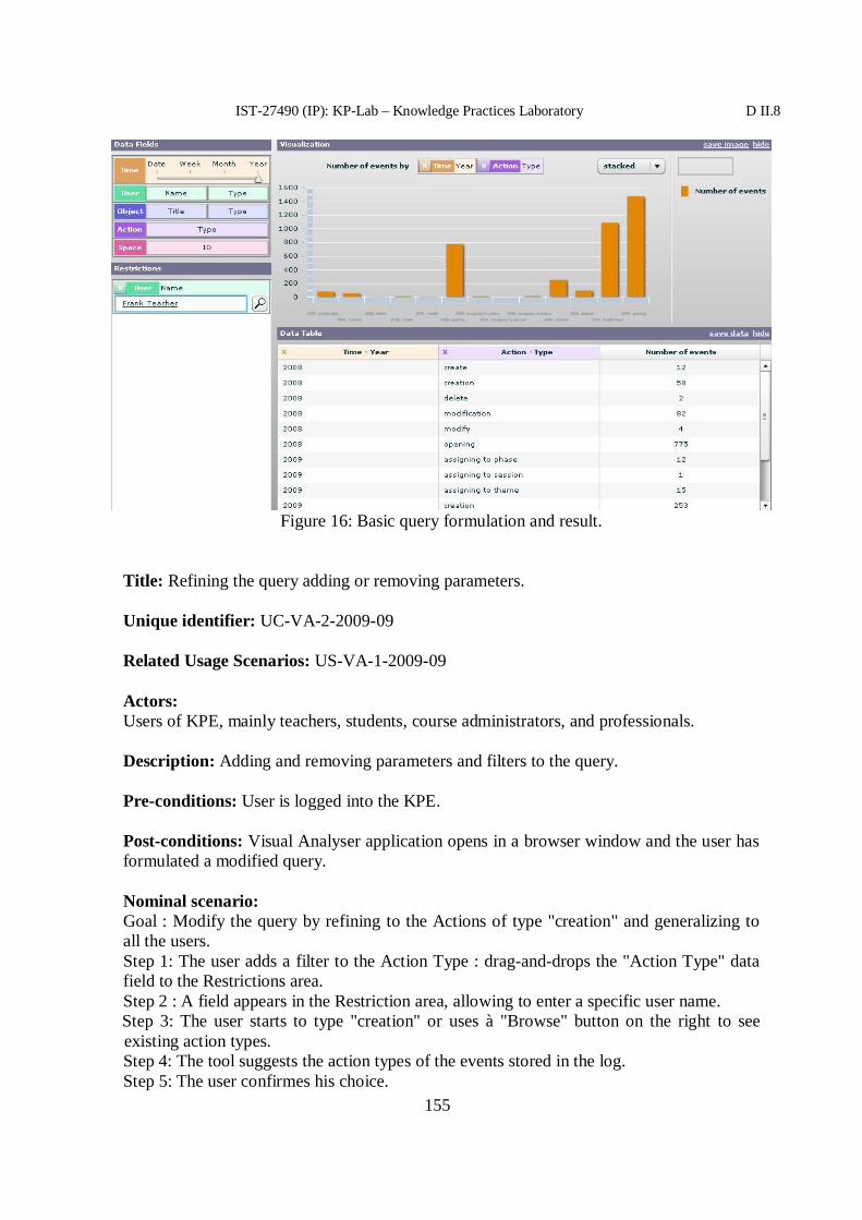
IST-27490 (IP): KP-Lab – Knowledge Practices Laboratory D II.8
155
Title: Refining the query adding or removing parameters.
Unique identifier: UC-VA-2-2009-09
Related Usage Scenarios: US-VA-1-2009-09
Actors:Users of KPE, mainly teachers, students, course administrators, and professionals.
Description: Adding and removing parameters and filters to the query.
Pre-conditions: User is logged into the KPE.
Post-conditions: Visual Analyser application opens in a browser window and the user hasformulated a modified query.
Nominal scenario:Goal : Modify the query by refining to the Actions of type "creation" and generalizing toall the users.Step 1: The user adds a filter to the Action Type : drag-and-drops the "Action Type" datafield to the Restrictions area.Step 2 : A field appears in the Restriction area, allowing to enter a specific user name.Step 3: The user starts to type "creation" or uses à "Browse" button on the right to seeexisting action types.Step 4: The tool suggests the action types of the events stored in the log.Step 5: The user confirmes his choice.
Figure 16: Basic query formulation and result.

IST-27490 (IP): KP-Lab – Knowledge Practices Laboratory D II.8
156
Step 6: When a valid value is entered, the result is shown by the tool (see Fig. 2)..Step 7: To remove the filter on user name, the user clicks on the "x" button on the left ofthe corresponding filter on the Restriction area.Step 8: The tool removes the filter and the shows the result.
Screens:
Figure 17: Adding a filter on the Action Type.

IST-27490 (IP): KP-Lab – Knowledge Practices Laboratory D II.8
157
Title: Adding a parameter to obtain a stacked diagram.
Unique identifier: UC-VA-3-2009-09
Related Usage Scenarios: US-VA-1-2009-09
Actors: Users of KPE, mainly teachers, students, course administrators, and professionals.Description: Modifying the query by adding a parameter to obtain a stacked diagram.
Pre-conditions: User is logged into the KPE.
Post-conditions: Visual Analyser application opens in a browser window and the user hasformulated a query resulting in a stacked diagram.
Nominal scenario:Goal : Compare object creation activities for different object types, using stackeddiagramm.Step 1: The user defines "Object Type" as a parameter for stacking, by drag-and-droppingit to the little box in the up-right corner of the Visualization area.Step 2: The tool shows the result, by visualizing the query result as a stacked diagramm.
Figure 18: Filter on User Name being removed.

IST-27490 (IP): KP-Lab – Knowledge Practices Laboratory D II.8
158
Screens:
Title: Downloading a predefined query.
Unique identifier: UC-VA-4-2009-09
Related Usage Scenarios: US-VA-2-2009-09
Actors: Users of KPE, mainly teachers, students, course administrators, and professionals.Description: Downloading a query which has been saved in the system previously.
Pre-conditions: User is logged into the KPE.
Post-conditions: Visual Analyser application opens in a browser window and some of thepreviously stored predefined queries have been loaded.
Nominal scenario:Step 1. The user clicks on the link "Predefined queries".Step 2. The system opens a pop-up menu with available queries, stored in the system.Step 3. The user chooses the query he wants to execute and confirms the choice by clickingOK.Step 4. The system loads the query and presents the result and its visualization.
Title: Saving the query as a predefined query.
Unique identifier: UC-VA-5-2009-09
Figure 19: Stacked diagram.

IST-27490 (IP): KP-Lab – Knowledge Practices Laboratory D II.8
159
Related Usage Scenarios: US-VA-2-2009-09
Actors: Users of KPE, mainly teachers, students, course administrators, and professionals.Description: Saving a query as one of the predefined queries for future use.
Pre-conditions: User is logged into the KPE.
Post-conditions: Visual Analyser application opens in a browser window and the user hasformulated a saved a new query.
Nominal scenario:Step 1. The user clicks on the link "save the query".Step 2. The system adds the formulated query to the set of predefined queries.
Title: Managing predefined queries.
Unique identifier: UC-VA-6-2009-09
Related Usage Scenarios: US-VA-2-2009-09
Actors: Users of KPE, mainly teachers, students, course administrators, and professionals.Description: Editing or deleting predefined queries.
Pre-conditions: User is logged into the KPE.
Post-conditions: Visual Analyser application opens in a browser window and somemodified queries are stored in the system.
Nominal scenario:Step 1. The user clicks on the link "Predefined queries".Step 2. The system opens a pop-up menu with available predefined queries.Step 3. The user browses the queries using usual keyboard keys, for each one (s)he canchose either to click on "edit" or "delete".Step 4. If "edit" is pressed, the system loads the query and shows its result, allowing theuser to modify parameters of the query.Step 5. The user modifies parameters of the query as desired, and presses OK button of thepop-up when finished.Step 6. The query is saved in the system.
Title: Saving the result of the query.
Unique identifier: UC-VA-7-2009-09
Related Usage Scenarios: US-VA-2-2009-09

IST-27490 (IP): KP-Lab – Knowledge Practices Laboratory D II.8
160
Actors: Users of KPE, mainly teachers, students, course administrators, and professionals.Description: Saving the result of the query and its visualization in a file.
Pre-conditions: User is logged into the KPE.
Post-conditions: Visual Analyser application opens in a browser window and a resultof a query has been saved.
Nominal scenario:Step 1. The user clicks on the link "save data" on the Data Table area if the result tableneeds to be saved.Step 2. The system opens a pop-up allowing choosing the location for the file.Step 3. The user chooses file name and a location on the disk.Step 4. The system creates a text file on the disk containing the result of the query (a subsetof the log satisfying conditions of the query).Step 5. The user clicks on the link "save image" on the Visualization area if thevisualization has to be saved.Step 6. The system opens a pop-up allowing choosing the location for the file.Step 3. The user chooses file name and a location on the disk.Step 4. The system creates a PNG file on the disk containing the visualization of the resultof the query.
Title: Defining groups of users for a query.
Unique identifier: UC-VA-8-2009-09
Related Usage Scenarios: US-VA-3-2009-09
Actors: User of the KPE, mainly teachers, students, course administrators, andprofessionals.Description: Formulating a query comparing activities of groups of users, groups beingdefined in ad hoc manner.
Pre-conditions: User is logged into the KPE.
Post-conditions: Visual Analyser application opens in a browser window.
Nominal scenario:Step 1. The user clicks on the "Define group" button below the Data Fields area.Step 2. The system opens a pop-up asking to give a name to the group.Step 3. The user types a name for the group.Step 4. The system opens a pop-up listing the user names.Step 5. The user chooses members of the group by clicking on the user name, then on"Add" button. When the group is complete, the user clicks on "Done" button.Step 6. The system returns to the main Visual Analyser screen, the defined group added tothe query parameters.

IST-27490 (IP): KP-Lab – Knowledge Practices Laboratory D II.8
161
3 Technical design
3.1 Software architecture
The Visual Analyser tool is designed as an independent Web Application, packaged in aWeb Archive (WAR), with all its server components, based on Apache Axis and clientcomponents, based on Adobe Flex.
3.1.1 Architecture detailsVisual Analyser is designed as a client-server application, the client handling the visualinteraction and the server managing query mapping and processing.
The client of Visual Analyser is designed as a web-application (integrated part of KPE), incharge of interaction with the user: presentation of the visual schema, transformation ofusers' actions into an analytical query and presentation of query result visually.
The server is designed to map the query, formulated by the user into the format suitable forthe evaluation service (see details below), and to map the result into a format suitable forthe client, for visualization. Only the client part of the tool is available to the users.
To evaluate the query, Visual Analyser consumes the services described above in section3.3. The Figure 20 shows the schema of interaction between the user, the client (interface),the server and the KP-Lab Knowledge Analysis Services (KAS).
Figure 20. Visual Analyser interaction sequence
3.1.2. Implementation details and internal web services

IST-27490 (IP): KP-Lab – Knowledge Practices Laboratory D II.8
162
The client of the VA tool is an Adobe Flex component, implementing VA interface,running in a browser.
The web service, provided by the client component of VA, has the following signature:
Object VAClient (Object query)
query parameter is an object, encapsulating users clicks. Users only access VA through itsinterface, so they do not have to handle the query parameter correct building, it is done bythe tool.The output is also an object, containing query result as visualized by the tool, either as atable, or a line-chart, etc.
Thus, VA client component transforms the user's clicks into a query saved in a XMLstring, and sends it to the VA server component. This XML string of query encapsulatesthe parameters of the query (classifier, measure and operation) and typically looks asfollows:
<query><classifier>
<function name="Action"/></classifier><measure>
<function name="EventId"/></measure><operation name="count"/>
</query>
VA server component is a Java program, handling query mapping into an input for theKnowledge Analysis Services (KAS) Aggregation Service, and the mapping of the resultinto a visualizable format (an XML string again).
The web-service provided by VA server side, which maps the XML string of query into aninput for the KP-Lab Knowledge Analysis Services (KAS) Aggregation Service, thensends it, gets the result back and returns it as an XML string, has the following signature:
String VAServer (String xmlQueryString)
where the input parameter xmlQueryString is a user's query in XML form (as an exampleabove), received from the client component of VA.The output string of XML has typically this look:
<Events><Event>
<Classifier>creation</Classifier><AggResult>2503</AggResult>
</Event><Event>
<Classifier>deletion</Classifier><AggResult>2</AggResult>
</Event><Event>

IST-27490 (IP): KP-Lab – Knowledge Practices Laboratory D II.8
163
<Classifier>modification</Classifier><AggResult>595</AggResult>
</Event></Events>
This web-service is consumed by VA client component.
3.2 GUI
The VA interface includes a Data Fields area, a Visualization area, a Data Table area, anda Restrictions area. In the Data Fields area the attributes used as criteria for analysis arelisted. The Visualization area is used to present the result of the query to the user. The DataTable area presents the result in a tabular form. Finally, the Restriction area allows the userto filter the result by chosen attributesvalues.
3.3 Collaboration with other tools
The Visual Analyser tool interoperates with the Aggregation Service from KnowledgeAnalysis Services (KAS) in order to evaluate users requests. The Aggregation service takesas an input a set of parameters of the query, which has been chosen and sent by the userthrough Visual Analyser. Then the query is evaluated over the log data, and the result issent to the Visual Analyser in order to be visualized and presented to the user.
Here is the Aggregation Service interface used by Visual Analyser:

IST-27490 (IP): KP-Lab – Knowledge Practices Laboratory D II.8
164
public String[][] getAggregations(String [] groupBy, Property[]restrictions, String operation, String operationAttribute, int from,int maxEvents);
The "groupBy" parameter can accept the following values:
1. subjectId2. subjectType3. objectId4. objectType5. actionType6. time7. SSPID8. User (this is user name)9. Title10. eventId - used to count all the events.
The used value for operation is COUNT. The values of operationAttributeis "eventId".
Currently, Visual Analyser is integrated into KPE in a loose way, as a plug-in.
4 References
[1] D4.1.1 Description of Work for Months 37-54. http://www.kp-lab.org/intranet/work-packages/wp1/description-of-work/dow4-1-1/DoW%204.1.1.3.zip/view

IST-27490 (IP): KP-Lab – Knowledge Practices Laboratory D II.8
165
Annex 8. Visual Model editor specifications

27490
KP-LAB
Knowledge Practices Laboratory
Integrated Project
Information Society Technologies
D6.8 M46 specification of end-user applications –Visual Model Editor
Due date of deliverable: 30/11/2009Actual submission date:
Start date of project: 1.2.2006 Duration: 60 Months
Organisation name of lead contractor for this deliverable: EVTEK
Revision [1.0]
Project co-funded by the European Commission within the Sixth Framework Programme(2002-2006)Dissemination LevelPU Public PUPP Restricted to other programme participants (including the CommissionRE Restricted to a group specified by the consortium (including the
CO Confidential, only for members of the consortium (including theCommission Services)

IST-27490 (IP): KP-Lab – Knowledge Practices Laboratory D II.8
167
Contributors:Name Partner organisation EmailVasko Tchoumatchenko TUSTania Vasileva TUSChristoph Richter FH-OÖHeidrun Allert FH-OÖEva Zoeserl FH-OÖ
Version history:Version Date Author(s) Description
Table of Contents
Table of Contents................................................................................................................ 1671 Introduction................................................................................................................. 168
1.1 Purpose................................................................................................................ 1681.2 Scope of the software .......................................................................................... 1681.3 Roadmap of the tool ............................................................................................ 1681.4 What is new in this version? ................................................................................ 1681.5 Definitions........................................................................................................... 169
2 User requirements ....................................................................................................... 1692.1 KP-Lab empirical research .................................................................................. 1692.2 Driving Objectives and High-Level Requirements ............................................... 1692.3 System usage scenarios........................................................................................ 1692.4 Use cases............................................................................................................. 170
2.4.1 Actors.......................................................................................................... 1702.4.2 Use Cases .................................................................................................... 1702.4.3 Detailed Use Cases ...................................................................................... 170
2.4.3.1 UC-VME-9-2009-11 Retrieving information on activities performed on avisual model ............................................................................................................ 1702.4.3.2 UC-VME-10-2009-11 Export of visual models ........................................ 171
3 Technical design ......................................................................................................... 1743.1 Software architecture........................................................................................... 1743.2 GUI ..................................................................................................................... 1743.3 Front end services................................................................................................ 1743.4 Collaboration with other tools.............................................................................. 177
4 References................................................................................................................... 177

IST-27490 (IP): KP-Lab – Knowledge Practices Laboratory D II.8
168
1 Introduction
1.1 Purpose
This document describes new functionality of the Visual Model Editor (VME) tool. Itconsists of use cases, mock-up screens; data model and describes the required modificationof the corresponding services.
1.2 Scope of the software
The Visual Model Editor (VME) is a tool for collaborative creation of visual models basedon visual modelling languages.
1.3 Roadmap of the tool
The updated roadmap of the Visual Model Editor is as follows:Iteration 1: Feasibility study, prototyping. Release v1.0Milestones: Release M28.
Iteration 2: Basic VME functionality (creating, editing, annotating, browsing visualmodels). Release v2.0Milestones: M21 Specification, M28 Prototype, M32 Stable release
Iteration 3: Advanced VME functions, integration with the Visual Modeling LanguagesEditor. Release 2.1Milestones: M33 Updated software requirements specification (the present document),M35 prototype, M36 stable release.
Iteration 4: Maintenance release, which will include the new functionality described in thisdocument. Release 2.2.Milestones: M46 Specifications, M48 Production release.
Iteration 5: Final release with improvements and bug fixes of v2.2 based on user trials.Release 3.0.Milestones: M56 Release.
1.4 What is new in this version?
Functionality for retrieving and analysing information on activities performed on a visualmodel.
The decision to integrate timeline analysis for visual models and visual modelinglanguages into the corresponding tools (VME and VMLE) instead of using the timelinebased analyzer (TLBA) only is motivated by the need to trace the evolution of the internalstructure of these types of content items in detail. While the TLBA is aimed to analyze the

IST-27490 (IP): KP-Lab – Knowledge Practices Laboratory D II.8
169
evolution of a set of content items and their interrelations against the contributors involved,the timeline analysis for VMs and VMLs provides a look into the evolution of visualmodels and visual modeling languages as complex and semantically rich entities. As aconsequence the requirements for the timeline analysis for visual models and modelinglanguages differ from those of the TLBA. While the TLBA emphasizes phenomena such asauthorship, re-uptake of content items, referencing and annotation, the timeline analysis forvisual models and modeling languages focuses on the direct comparison of structure andcontents of a model or language at various points in time.
1.5 Definitions
Visual model (VM) –two-dimensional graph-structured visual representation of a certainobject of interest such as flow-charts, argument-graphs, organigrams, decision trees,program logic models, use case diagrams, conceptual maps, etc.
Visual modelling language (VML) – formal specification, which defines the syntax andvisual appearance of a model and the semantics of modelling elements used.
2 User requirements
2.1 KP-Lab empirical research
The tool functionalities specified in this document will be used in the following KP-Labempirical research cases [2]:
Case 3: Conceptual modelling in Design Projects
2.2 Driving Objectives and High-Level Requirements
The specifications presented in this document are related to the following drivingobjectives (DO) and high-level requirements (HLR) [1]:
DO9 Users are provided with history on content development and work process advancementHLR9.1 Users can track the evolution and changes of knowledge objects and find out their
authors and contributors (sequences of performed steps in time, incl. versioning)HLR9.2 Users are provided with customized summaries about the knowledge objects
available within the shared environment (e.g. users might request an overview of thetasks completed within the last 2 weeks or the interactions of people within a sharedworkspace)
DO13 Users can collect data about activities and interactions systematically and over longer periodsof time
HLR13.5 Users can customise the way they want to retrieve wanted data for analysis.HLR13.6 Users are provided with summative information on performed actions (e.g. added
comments, created tasks, modifications in metadata, background materials fordecisions, etc.). (Rephrased)
2.3 System usage scenarios
US-VM(L)E-5-2009-09: Export of visual models

IST-27490 (IP): KP-Lab – Knowledge Practices Laboratory D II.8
170
US-VM(L)E-6-2009-09: Retrieving information on activities performed on a visual model(history)
2.4 Use cases
The VME use cases, described in this document, allow users to explore information aboutthe activities performed on a certain visual model and to trace the evolution of the modelover time1.
2.4.1 Actors
VME users – both students and researchers.
2.4.2 Use Cases
UC-VME-9-2009-11 - Retrieving information on activities performed on a visual modelUC-VME-10-2009-11 - Export of visual models
2.4.3 Detailed Use Cases
2.4.3.1 UC-VME-9-2009-11 Retrieving information on activities performed on avisual model
Title: Retrieving information on activities performed on a visual model (history)
Unique identifier: UC-VME-9-2009-11
Related System Usage Scenarios: US-VM(L)E-6-2009-09: Retrieving information onactivities performed on a visual model (history)
Actors: KPE user
Description:
The idea of this system usage scenario is to allow users to explore information about theactivities performed on a certain visual model and to trace the evolution of the model overtime.
The timeline based view on a visual model can be launched via the context menu of thevisual model in content or tailored view. Once the user selects “view object’s timeline” apop-up window appears on to of the current view.The user can define the timeframe s/he is interested in and select single events for closerinspection. For every event and image of the visual model at that particular point as well asinformation about the kind of changes made are provided.
Pre-conditions: Shared space with at least one visual model.
Post-conditions: none

IST-27490 (IP): KP-Lab – Knowledge Practices Laboratory D II.8
171
Nominal scenario:3. The user right-clicks on the visual model item in the content view or tailored view
and selects from the context-menu “view object’s timeline”.4. A pop-up window, similarly to the navigator tool, appears on top of the current
view.5. The user can select a particular timeframe and scroll through the timeline. S/he can
also select a particular event and an image of the visual model at that point in timeis provided together with additional information about the changes made.
Non-Functional Requirements:none
Screen mock-ups:
Figure 1. User interface sketch for timeline view. A slider with zooming functionality isused to specify the actual timeframe. On the corresponding timeline each event is markedas a bar, whereby the width of the bar marks the time that elapsed since the last change hasbeen made, i.e. narrow bars indicate that changes occurred rapidly. In this case the user isprovided with for only one event at a time, but s/he can “scroll” through events by”moving” over the timeline.
2.4.3.2 UC-VME-10-2009-11 Export of visual modelsTitle: Export of visual models

IST-27490 (IP): KP-Lab – Knowledge Practices Laboratory D II.8
172
Unique identifier: UC-VME-10-2009-11
Related System Usage Scenarios:
US-VM(L)E-5-2009-09: Export of visual models
Actors: KPE user
Description:
The user wants to export a visual model from the KPE for further analysis. The export issupposed to provide aggregated information about the structure and contents of a model.
Pre-conditions: Shared space with at least one visual model.
Post-conditions: none
Nominal scenario:9. The user clicks on the export button next to the title of the visual model s/he wantsto export10. The system presents the exported model in textual format.11. The user copy/pastes the text into a spreadsheet.
Non-Functional Requirements:
No synchronization is required.
Screen mock-ups:

IST-27490 (IP): KP-Lab – Knowledge Practices Laboratory D II.8
173
Figure 2. VME User Interface – the Export button is under the model title.
Figure 3. Model Export – Pop-up window containing textual description of the visualmodel.

IST-27490 (IP): KP-Lab – Knowledge Practices Laboratory D II.8
174
3 Technical design
3.1 Software architecture
The VME tool consists of VME Client (part of the KPE GUI) and CSM Service.
For the development of the VME analytical functionality the CSMservice API is modifiedto include additional information.
The VME history log records are stored in the HPA awareness repository.
3.2 GUI
l The screen design is shown on figure 2 and 3.
l Web Services used – CSMService, HPA awareness service
3.3 Front end services
The following CSMService operations are related to the VME analytical functions:createConcept, createRelation, deleteConcept, delateRelation, modifyConcept,modifyRelation, exportModel.

IST-27490 (IP): KP-Lab – Knowledge Practices Laboratory D II.8
175
For each of them the API is updated to include information, required for the recording ofmodel history. The added information includes the full name of the user who invoked theoperation, the visual model URI, the shared space URI and the coordinates of the visualmodel elements.The exportModel operation is specifically developed to support the two use cases: UC-VME-9-2009-11 - Retrieving information on activities performed on a visual model(history) andUC-VME-10-2009-11 - Export of visual models.The request format is as follows: <soapenv:Body> <ser:exportModel> <exportModelRequest> <sharedSpaceUri>URI of the shared space</sharedSpaceUri> <sspName>Shared space name</sspName> <user>uer name</user> <visualModelUri>viusal model URI</visualModelUri> </exportModelRequest> </ser:exportModel> </soapenv:Body></soapenv:Envelope>
The response consists of two parts: textual description of the visual model at the momentthe operation was invoked and history of all model changes.
Model Export formatHeader – model title, VML used for the model, shared space name, date of exportNodes – list of model nodes with their properties
Links – list of model links with their propertiesIncidence matrix – describes the model's graph
Examle:Model title: M2Date of export: 2009-11-07 22:06Shared space: VME Test 1Exported by: Vasko TchoumatchenkoModelling language: Design Knowledge Mapping Language--- Nodes --- id: N1 type: Factor title: Strong group cohesion description:
id: N2 type: Factor title: Self censorship description:

IST-27490 (IP): KP-Lab – Knowledge Practices Laboratory D II.8
176
...
--- Links --- id: L1 type: has positive effect title: has positive effect description:
id: L2 type: has positive effect title: has positive effect description:
id: L3 type: has negative effect title: has negative effect description:
...
--- Incidence Matrix ---from\to,N1,N2,N3,N4,N5,N6,N7,N8,N9,N10,N1,,,,,,,,,L6 ,,N2,,,,,,,,,,,N3,,,,,,,,,L1 ,,N4,,,,,,,,,,,N5,,,,,,,,,L5 ,,N6,,,,,,,,,L8 ,,N7,,,,,,,,,,,N8,,,,,,,,,L7 ,,N9,,L3 ,,L2 ,,,L9 ,,,L4 ,N10,,,,,,,,,,,
Model history format
The model history is presented as list of records. Each record corresponds to one of thefollowing model modifications:
− create (concept or relationship)− delete (concept or relationship)− modify property
The record format is the following:Event number; Date; User; Object ID ; Object Name; Object Type; Action; Details
Examples
Typical concept creation records:

IST-27490 (IP): KP-Lab – Knowledge Practices Laboratory D II.8
177
1;2009-11-16 18:15:44;User Paul;N1;Factor;Factor;CREATE;2;2009-11-16 18:15:55;User Paul;N1;Factor;Factor;DELETE;3;2009-11-16 18:16:14;User Paul;N2;Factor;Factor;CREATE;
Property modification records:
4;2009-11-16 18:17:53;User Paul;N2;Factor: TechnischeAnforderungen;Factor;MODIFY;title = Factor: Technische Anforderungen5;2009-11-16 18:17:54;User Paul;N2;Factor: TechnischeAnforderungen;Factor;MODIFY;description = PC, Micro Kopfhoerer,Internetverbindung
Relationships creation records:
15;2009-11-16 18:23:11;User Paul;L1;Link from Factor: Technische Anforderungen (N2)to Factor: Ort (N3);has positive effect;CREATE;16;2009-11-16 18:23:31;User Paul;L1;Link from Factor: Technische Anforderungen (N2)to Factor: Ort (N3);has positive effect;DELETE;17;2009-11-16 18:23:39;User Paul;L2;Link from Factor: Technische Anforderungen (N2)to Factor: Zeitersparnis (N4);has positive effect;CREATE;
3.4 Collaboration with other tools
The VME client is integrated in the KPE content view. The model languages used in VMEare developed within the Visual Modeling Language Editor tool. The VME timeline viewis integrated with the Timeline Based Analyser tool.
4 References[1] D2.4 Driving Objectives and High-level Requirements for KP-Lab Technologies
(revised version). http://www.kp-lab.org/intranet/work-packages/wp2/result/D2.4_Resubmission_290809.doc
[2] D3.2 A comprehensive research strategy (an updated and revised version for years4 and 5). http://www.kp-lab.org/intranet/work-packages/wp1/submission-to-commission-23-9.2009/D3.2-Rev-Research-Strategy_September_submitted.doc

IST-27490 (IP): KP-Lab – Knowledge Practices Laboratory D II.8
178
Annex 9. Visual Modelling Language Editor specifications

27490
KP-LAB
Knowledge Practices Laboratory
Integrated Project
Information Society Technologies
D6.8 M46 specification of end-user applications –Visual Modelling Languages Editor
Due date of deliverable: 30/11/2009Actual submission date:
Start date of project: 1.2.2006 Duration: 60 Months
Organisation name of lead contractor for this deliverable: EVTEK
Revision [1.0]
Project co-funded by the European Commission within the Sixth Framework Programme(2002-2006)Dissemination LevelPU Public PUPP Restricted to other programme participants (including the CommissionRE Restricted to a group specified by the consortium (including the
CO Confidential, only for members of the consortium (including theCommission Services)

IST-27490 (IP): KP-Lab – Knowledge Practices Laboratory DII.8
180
Contributors:Name Partner organisation EmailVasko Tchoumatchenko TUSTania Vasileva TUSChristoph Richter FH-OÖHeidrun Allert FH-OÖEva Zoeserl FH-OÖ
Version history:Version Date Author(s) Description
Table of Contents
1 Introduction............................................................................................................1821.1 Purpose...........................................................................................................1821.2 Scope of the software .....................................................................................1821.3 Roadmap of the tool .......................................................................................1821.4 What is new in this version? ...........................................................................1821.5 Definitions......................................................................................................183
2 User requirements ..................................................................................................1832.1 KP-Lab empirical research .............................................................................1832.2 Driving Objectives and High-Level Requirements ..........................................1832.3 System usage scenarios...................................................................................1842.4 Use cases........................................................................................................184
2.4.1 Actors.....................................................................................................1842.4.2 Use Cases ...............................................................................................1842.4.3 Detailed Use Cases .................................................................................185
2.4.3.1 UC-VMLE-1 Browsing available VMLs.............................................1852.4.3.2 UC-VMLE-2 Creating a VML ............................................................1852.4.3.3 UC-VMLE-3 Copying a VML ............................................................1862.4.3.4 UC-VMLE-4 Opening VML for editing..............................................1862.4.3.5 UC-VMLE-5 Adding a concept...........................................................1872.4.3.6 UC-VMLE-6 Adding an attribute........................................................1882.4.3.7 UC-VMLE-7 Adding a link.................................................................1892.4.3.8 UC-VMLE-8 Deleting concepts, attributes and links...........................1892.4.3.9 UC-VMLE-9 Updating concepts and attributes ...................................1902.4.3.10 UC-VMLE-10 Check VML consistency..........................................1912.4.3.11 UC-VMLE-11 Retrieving information on activities performed on aVML 1912.4.3.12 UC-VMLE-13 Export of VML........................................................192
3 Technical design ....................................................................................................1923.1 Software architecture......................................................................................1923.2 GUI ................................................................................................................193

IST-27490 (IP): KP-Lab – Knowledge Practices Laboratory DII.8
181
3.3 Front end services...........................................................................................1933.3.1.1 Technical VMLE use cases .................................................................193
3.3.2 Save........................................................................................................1953.3.3 Save As...................................................................................................1953.3.4 Check .....................................................................................................1963.3.5 Delete .....................................................................................................1963.3.6 Modify....................................................................................................196
3.3.6.1 VML Export format ............................................................................1973.3.6.2 VML history format ............................................................................197
3.4 Collaboration with other tools.........................................................................1974 References..............................................................................................................197

IST-27490 (IP): KP-Lab – Knowledge Practices Laboratory DII.8
182
1 Introduction
1.1 Purpose
This document describes the functionality of the Visual Modelling Language Editor. Itconsists of use cases, UI screens and describes the required KP-LAB services.
1.2 Scope of the software
The Visual Modelling Language Editor (VMLE) is a tool for collaborative development ofvisual modelling languages to be used in conjunction with the Visual Model Editor (VME).
1.3 Roadmap of the tool
The updated roadmap of the Visual Modelling Language Editor is as follows:
Iteration 1: Design, prototyping. Release v1.0Milestones: M33 Specification, M36 Prototype
Iteration 2: Basic VMLE functions - browsing available visual modelling languages(VMLs), creating, copying, commenting and editing VMLs. Adding, editing, commentingand deleting concepts and relations to a VML. Release v2.0Milestones: M37 Updated software requirements, M39 prototype, M40 stable release.
Iteration 3: Advanced VMLE functions (comparing visual modelling languages, updating avisual model according to changes in the VML), Release 3.0
Iteration 4: Maintenance release, which will include optimized data model and front-endservice operations in order to address functional and performance deficiencies of theprevious releases. Release 3.2.Milestones: M46 Specifications, M48 Production release.
Iteration 5: Final release with improvements and bug fixes of v3.2 based on user trials.Release 4.0.Milestones: M56 Release.
1.4 What is new in this version?
The principal difference, compared to the previous VMLE prototypes, is a new data model,architecture and implementation of the front end service. The redesign is required becausethe previous prototypes were not able to achieve functional completeness and acceptableperformance.
From a functional point of view a new history analysis and export capabilities will beimplemented.
The decision to integrate timeline analysis for visual models and visual modelinglanguages into the corresponding tools (VME and VMLE) instead of using the timelinebased analyzer (TLBA) only is motivated by the need to trace the evolution of the internal
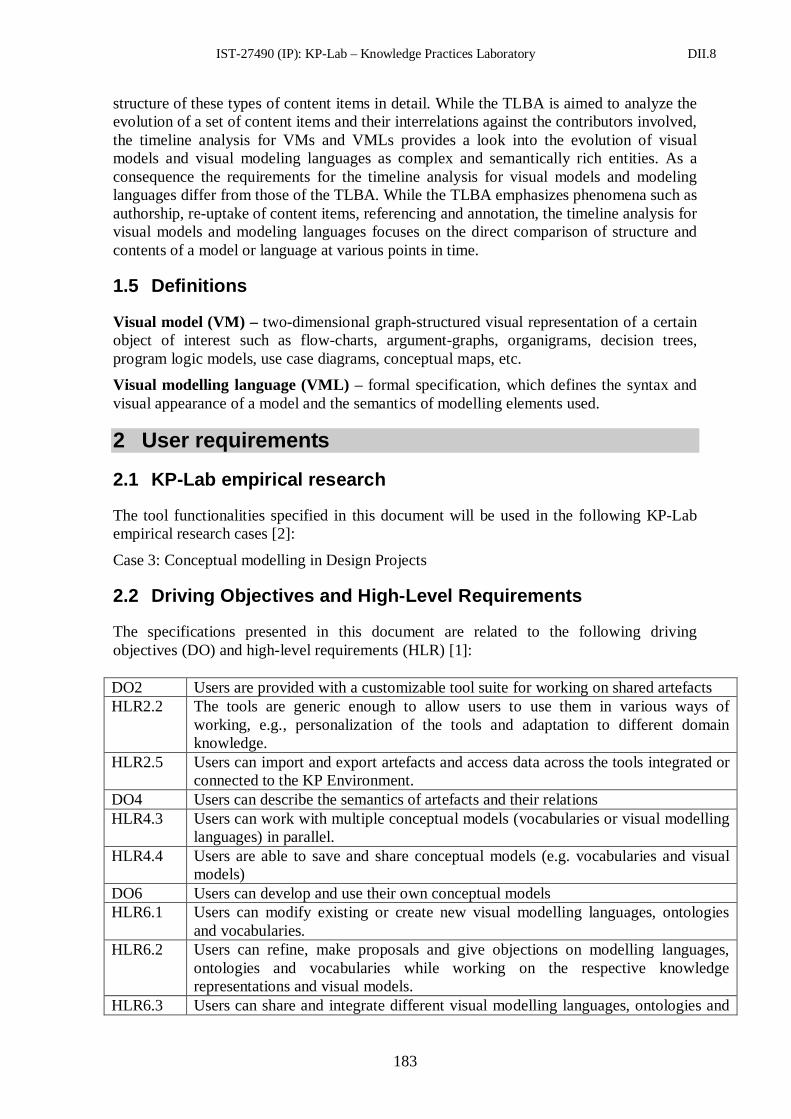
IST-27490 (IP): KP-Lab – Knowledge Practices Laboratory DII.8
183
structure of these types of content items in detail. While the TLBA is aimed to analyze theevolution of a set of content items and their interrelations against the contributors involved,the timeline analysis for VMs and VMLs provides a look into the evolution of visualmodels and visual modeling languages as complex and semantically rich entities. As aconsequence the requirements for the timeline analysis for visual models and modelinglanguages differ from those of the TLBA. While the TLBA emphasizes phenomena such asauthorship, re-uptake of content items, referencing and annotation, the timeline analysis forvisual models and modeling languages focuses on the direct comparison of structure andcontents of a model or language at various points in time.
1.5 Definitions
Visual model (VM) –two-dimensional graph-structured visual representation of a certainobject of interest such as flow-charts, argument-graphs, organigrams, decision trees,program logic models, use case diagrams, conceptual maps, etc.Visual modelling language (VML) – formal specification, which defines the syntax andvisual appearance of a model and the semantics of modelling elements used.
2 User requirements
2.1 KP-Lab empirical research
The tool functionalities specified in this document will be used in the following KP-Labempirical research cases [2]:
Case 3: Conceptual modelling in Design Projects
2.2 Driving Objectives and High-Level Requirements
The specifications presented in this document are related to the following drivingobjectives (DO) and high-level requirements (HLR) [1]:
DO2 Users are provided with a customizable tool suite for working on shared artefactsHLR2.2 The tools are generic enough to allow users to use them in various ways of
working, e.g., personalization of the tools and adaptation to different domainknowledge.
HLR2.5 Users can import and export artefacts and access data across the tools integrated orconnected to the KP Environment.
DO4 Users can describe the semantics of artefacts and their relationsHLR4.3 Users can work with multiple conceptual models (vocabularies or visual modelling
languages) in parallel.HLR4.4 Users are able to save and share conceptual models (e.g. vocabularies and visual
models)DO6 Users can develop and use their own conceptual modelsHLR6.1 Users can modify existing or create new visual modelling languages, ontologies
and vocabularies.HLR6.2 Users can refine, make proposals and give objections on modelling languages,
ontologies and vocabularies while working on the respective knowledgerepresentations and visual models.
HLR6.3 Users can share and integrate different visual modelling languages, ontologies and

IST-27490 (IP): KP-Lab – Knowledge Practices Laboratory DII.8
184
vocabularies.DO9 Users are provided with history on content development and work process
advancementHLR9.1 Users can track the evolution and changes of knowledge objects and find out their
authors and contributors (sequences of performed steps in time, incl. versioning)HLR9.2 Users are provided with customized summaries about the knowledge objects
available within the shared environment (e.g. users might request an overview ofthe tasks completed within the last 2 weeks or the interactions of people within ashared workspace)
DO13 Users can collect data about activities and interactions systematically and overlonger periods of time
HLR13.5 Users can customise the way they want to retrieve wanted data for analysis.HLR13.6 Users are provided with summative information on performed actions (e.g. added
comments, created tasks, modifications in metadata, background materials fordecisions, etc.). (Rephrased)
2.3 System usage scenarios
US-VM(L)E-2-2009-09 Creating and editing a visual modelling languageUS-VM(L)E-3-2009-09 Migrating to a new version of a Visual Modelling LanguageUS-VM(L)E-5-2009-09: Export of visual models (extended to visual modelling languages)US-VM(L)E-6-2009-09: Retrieving information on activities performed on a visual model(extended to visual modelling languages)
2.4 Use cases
This section presents the use cases for the visual model editor.
2.4.1 Actors
VMLE users – both students and researchers.
2.4.2 Use Cases
UC-VMLE-1 Browsing available VMLsUC-VMLE-2 Creating a VMLUC-VMLE-3 Copying a VMLUC-VMLE-4 Opening VML for editingUC-VMLE-5 Adding a conceptUC-VMLE-6 Adding an attributeUC-VMLE-7 Adding a linkUC-VMLE-8 Deleting concepts, attributes and linksUC-VMLE-9 Updating concepts and attributesUC-VMLE-10 Check VML consistencyUC-VMLE-11 Retrieving information on activities performed on a VML (history)UC-VMLE-12 Export of VML

IST-27490 (IP): KP-Lab – Knowledge Practices Laboratory DII.8
185
2.4.3 Detailed Use Cases
2.4.3.1 UC-VMLE-1: Browsing available VMLsTitle: Browsing the set of available VMLsUnique identifier: UC-VMLE-1Related Usage Scenarios: US-VM(L)E-2-2009-09 Creating and editing a visualmodelling languageActors: The users of the visual modelling language editor.Description: The user wants to see the visual modelling languages available in a particularshared space.Pre-conditions: The user has entered a shared space.Post-conditions: none
Nominal scenario:6. The user enters the content view or a tailored view.
7. The system shows the content items, available in the selected view.8. The user identifies the visual modelling languages by their specific icon.
Extensions:9. The user clicks the right mouse button and selects the function “add visual model”
from the pop-up menu.10. The system shows a form, which contains a list of the available visual modelling
languages and a short description of each language.Non-Functional Requirements: None
Screen mock-ups:
Content view with visual modelling language.
2.4.3.2 UC-VMLE-2 Creating a VMLTitle: Creating a Visual Modelling LanguageUnique identifier: UC-VMLE-2Related System Usage Scenarios: US-VM(L)E-2-2009-09 Creating and editing a visualmodelling languageActors: VMLE usersDescription: The user wants to create a new visual modelling language.

IST-27490 (IP): KP-Lab – Knowledge Practices Laboratory DII.8
186
Pre-conditions: The user has entered a shared space and is in the content view or atailored view.Post-conditions: A new VML, together with the corresponding content item is created.Nominal scenario:
− The user clicks the right mouse button selects the “add content item” entry and thenthe function “add visual modelling language” from the pop-up menu.
− The system shows a form with fields for title and description of the new visualmodelling language.
− The user fills in the form for the modelling language and clicks on “ok” button.
− The system creates a new content item and adds it to the current shared space.Non-Functional Requirements: noneScreen mock-ups: none
2.4.3.3 UC-VMLE-3 Copying a VMLTitle: Copying a Visual Modelling LanguageUnique identifier: UC-VMLE-3Related System Usage Scenarios: US-VM(L)E-2-2009-09 Creating and editing a visualmodelling languageActors: VMLE usersDescription: The user wants to create a copy of an existing visual modelling language.
Pre-conditions:The user has entered a shared space and is in the content view or a tailored view.The user has opened a VML in the VMLE.Post-conditions:A new VML, together with the corresponding content item is created.Nominal scenario:
12. The user clicks on the “Save As” button in the VMLE.13. The system shows a form with fields for title and description of the new visual
modelling language.14. The user fills in the form for the modelling language and clicks on “ok” button.15. The system creates a new VML and adds it to the current shared space.
Non-Functional Requirements: noneScreen mock-ups:none2.4.3.4 UC-VMLE-4 Opening VML for editingTitle: Editing Visual Modelling LanguagesUnique identifier: UC-VMLE-4Related Usage Scenarios: US-VM(L)E-2-2009-09 Creating and editing a visualmodelling language

IST-27490 (IP): KP-Lab – Knowledge Practices Laboratory DII.8
187
Actors: The users of the visual modelling language editor.Description: The user wants to work on a visual modelling language.
Pre-conditions:The user has entered a shared space and is in the content view or a tailored view.
Post-conditions:The modified modelling language is saved.
Nominal scenario:l The user double-clicks on a VML or selects "open" from the VML's context menu.l The system shows the VML tree in the VMLE view (see the mock up).
Non-Functional Requirements:NoneScreen mock-ups:
Figure 1. VMLE UI mockup
2.4.3.5 UC-VMLE-5 Adding a conceptTitle: Adding a conceptUnique identifier: UC-VMLE-5Related Usage Scenarios: US-VM(L)E-2-2009-09 Creating and editing a visualmodelling language

IST-27490 (IP): KP-Lab – Knowledge Practices Laboratory DII.8
188
Actors: The users of the visual modelling language editor.Description: The user wants to add a concept to the VML
Pre-conditions:The user has opened a VML in the VMLE.
Post-conditions:The modified modelling language is saved.
Nominal scenario:[2] User clicks on the "concept" button (see Figure 1).
[3] VMLE shows a form:[4] "name" (required) - TextInput
[5] "scope note" (optional) - TextArea[6] "vertex" - RadioButton
[7] "edge" - RadioButton[8] "colour" - ColorPicker
[9] User fills the form and clicks OK.[10] VMLE creates concept graph node and places it on the screen.
Non-Functional Requirements:NoneScreen mock-ups:
2.4.3.6 UC-VMLE-6 Adding an attributeTitle: Adding an attributeUnique identifier: UC-VMLE-6Related Usage Scenarios: US-VM(L)E-2-2009-09 Creating and editing a visualmodelling languageActors: The users of the visual modelling language editor.Description: The user wants to add attribute to the VML.
Pre-conditions:The user has opened a VML in the VMLE.
Post-conditions:The modified modelling language is saved.
Nominal scenario:11. User clicks on the "attribute" button.
12. VMLE shows a form with two fields:- "name" (required) - TextInput- "scope note" (optional) - TextArea
13. User fills the form and clicks OK

IST-27490 (IP): KP-Lab – Knowledge Practices Laboratory DII.8
189
14. VMLE creates attribute graph node and places it on the screen.
Non-Functional Requirements:NoneScreen mock-ups:
2.4.3.7 UC-VMLE-7 Adding a linkTitle: Adding a linkUnique identifier: UC-VMLE-7Related Usage Scenarios: US-VM(L)E-2-2009-09 Creating and editing a visualmodelling languageActors: The users of the visual modelling language editor.Description: The user wants to add “is-a” or “has-attribute” link.
Pre-conditions:The user has opened a VML in the VMLE.
Post-conditions:The modified modelling language is saved.Nominal scenario:
Creation of “is-a” link
• User clicks on the "is-a" button.
• VMLE enters "linking" mode.
• User clicks on node of type "concept" and drags the mouse to a second node of type"concept". Nodes on type "attribute" can not be selected.
• VMLE creates "is-a" link between the selected concepts.Creation of “has-attribute” link
• User clicks on the "has-attribute" button.
• VMLE enters "linking" mode.
• User clicks on node of type "concept" and drags the mouse to a second node of type"attribute".orUser clicks on node of type "attribute" and drags the mouse to a second node oftype "concept".
• VMLE creates "has-attribute" link between the selected concept and attribute.Non-Functional Requirements:None
Screen mock-ups:
2.4.3.8 UC-VMLE-8 Deleting concepts, attributes and linksTitle: Deleting concepts, attributes and linksUnique identifier: UC-VMLE-8

IST-27490 (IP): KP-Lab – Knowledge Practices Laboratory DII.8
190
Related Usage Scenarios: US-VM(L)E-2-2009-09 Creating and editing a visualmodelling languageActors: The users of the visual modelling language editor.Description: The user wants to delete VML element.
Pre-conditions:The user has opened a VML in the VMLE.
Post-conditions:The modified modelling language is saved.
Nominal scenario:l user selects Concept, Attribute or Linkl user selects Delete from the context menu or presses the Delete button from the
keyboard.l The system asks for confirmationl If the user confirms the deletion, the system removes the selected items from the
model and refreshes the screen.
Non-Functional Requirements:None
Screen mock-ups:
2.4.3.9 UC-VMLE-9 Updating concepts and attributesTitle: Updating concepts and attributesUnique identifier: UC-VMLE-9Related Usage Scenarios: US-VM(L)E-2-2009-09 Creating and editing a visualmodelling languageActors: The users of the visual modelling language editor.Description: The user wants to update VML concept or attribute.Pre-conditions:The user has opened a VML in the VMLE.Post-conditions:The modified modelling language is saved.
Nominal scenario:
• User double clicks on Concept or Attribute (or selects the graph element andchooses Modify from the context menu)
• The system locks the graph element.• The system shows the same form which was used when creating the Concept or
Attribute.• The user modifies the form's content and clicks OK.
• The system un-locks the graph element.Non-Functional Requirements:

IST-27490 (IP): KP-Lab – Knowledge Practices Laboratory DII.8
191
NoneScreen mock-ups:
2.4.3.10 UC-VMLE-10 Check VML consistencyTitle: Check VML consistencyUnique identifier: UC-VMLE-Related Usage Scenarios: US-VM(L)E-2-2009-09 Creating and editing a visualmodelling languageActors: The users of the visual modelling language editor.Description: The user wants to validate the consistency of the created VML.
Pre-conditions:The user has opened a VML in the VMLE.
Post-conditions:The modified modelling language is saved.
Nominal scenario:1. User clicks on the "Check" button.2. VMLE shows the errors on the VML graph:
- The problematic VML elements are highlighted (in red or similar distinctivecolour).- The tool-tips for these VML elements are replaces with the corresponding errormessages.
Non-Functional Requirements:None
Screen mock-ups:
2.4.3.11 UC-VMLE-11 Retrieving information on activities performed on a VMLTitle: Retrieving information on activities performed on a VMLUnique identifier: UC-VMLE-11Related Usage Scenarios: US-VM(L)E-6-2009-09: Retrieving information on activitiesperformed on a visual model (or language)Actors: The users of the visual modelling language editor.
Description:The idea of this system usage scenario is to allow users to explore information about theactivities performed on a certain visual modelling language and to trace the evolution ofthe model over time. The history log is structured as table and is available to the user aspart of the VMLE model export output.Pre-conditions:none
Post-conditions:none

IST-27490 (IP): KP-Lab – Knowledge Practices Laboratory DII.8
192
Nominal scenario:
• The user clicks on the export button• The system presents the exported model in textual format.• The user copy/paste the text into a spreadsheet.
Non-Functional Requirements:None
Screen mock-ups:none
2.4.3.12 UC-VMLE-13 Export of VMLTitle:Unique identifier: UC-VMLE-Related Usage Scenarios: US-VM(L)E-5-2009-09: Export of visual models (orlanguages)Actors: The users of the visual modelling language editor.Description: The user wants to export a visual model from the KPE for further analysis.The export is supposed to provide aggregated information about the structure and contentsof a model.Pre-conditions:The user has opened a VML in the VMLE.Post-conditions:noneNominal scenario:
• The user clicks on the export button• The system presents the exported model in textual format.• The user copy/paste the text into a spreadsheet.
Non-Functional Requirements:none
Screen mock-ups:none
3 Technical design
3.1 Software architecture
The VMLE tool consists of VMLE Client (part of the KPE GUI) and CSM Service.
The VMLE specific log history is stored in HPA awareness service.The VMLs are stored in a graph database.

IST-27490 (IP): KP-Lab – Knowledge Practices Laboratory DII.8
193
Figure 2. VMLE in the KPE Architecture
3.2 GUI
• The preliminary screen design is shown on figure 1.
• Web Services used – CSMService, HPA awareness service
3.3 Front end services
VMLE relies on the following front-end services:• Real Time Data Access Service – for synchronization and locking• CSMService – VML storage and retrieval, log history storage and retrieval, VML
consistency checking• ContentItem Service – for creation of VML content items.
The VMLE specific CSMService operations are described in the following technical use-cases.
3.3.1.1 Technical VMLE use casesOpen VML for editing
• In the Content View, the user double-clicks on a VML or selects "open" VML fromthe context menu.
• The system starts the VMLE and initializes it with the following info:- Shared Space URI

IST-27490 (IP): KP-Lab – Knowledge Practices Laboratory DII.8
194
- VML URI (this is the URI of the VML content item)- full name of the current user
• VMLE calls CSMService:VmlDescription vml = getVml( String vmlUri )
The VmlDescription consists of list of nodes and links, together with properties (name,scope note, startNode, endNode, etc.) and coordinates. The detailed format is not yetspecified.
• VMLE draws the VML tree on the screen.
Add "concept"
- User clicks on the "concept" button.- VMLE shows a form:
- "name" (required) - TextInput- "scope note" (optional) - TextArea- "vertex" - RadioButton- "edge" - RadioButton- "colour" - ColorPicker
- User fills the form and clicks OK.
- VMLE calls CSMService:String uri = addVmlConcept( String sharedSpaceUri, String vmlUri, String userFullName ,String name, String scopeNote, String colour, boolean isVertex, int xCoord, int yCoord)
where "isVertex" is true if the "vertex" RadioButton is selected.
• VMLE creates concept node display object with "uri", "name" and "scope note"properties and places it on the screen.
Add "attribute"
• User clicks on the "attribute" button.
• VMLE shows a form with two fields:- "name" (required) - TextInput- "scope note" (optional) - TextArea
• User fills the form and clicks OK.
• VMLE calls CSMService:String uri = addVmlAttribute( String sharedSpaceUri, String vmlUri, String userFullName, String name, String scopeNote, int xCoord, int yCoord);
• VMLE creates attribute node display object with "uri", "name" and "scope note"properties and places it on the screen.
Add "is-a" link• User clicks on the "is-a" button.
• VMLE enters "linking" mode.

IST-27490 (IP): KP-Lab – Knowledge Practices Laboratory DII.8
195
• User clicks on node of type "concept" (let's call it startNode) and drags the mouseto a second node of type "concept" (endNode). Nodes on type "attribute" can not beselected.
• VMLE calls CSMService:String uri = addVmlLink( String sharedSpaceUri, String vmlUri, String userFullName,String startNodeUri, String endNodeUri, boolean true);
• VMLE creates "is-a" link display object with "uri" property.
Add "has-attribute" link• User clicks on the "has-attribute" button.
• VMLE enters "linking" mode.
• User clicks on node of type "concept" (conceptNode) and drags the mouse to asecond node of type "attrbute" (attrbuteNode).
• VMLE calls CSMService:
String uri = addVmlLink( String sharedSpaceUri, String vmlUri, String userFullName,String startNodeUri, String endNodeUri, boolean false);
• VMLE creates "has-attribute" link display object with "uri" property.
3.3.2 Save
• User clicks on the "Save" button.
• VMLE calls CSMService:String version = saveVml( String sharedSpaceUri, String vmlUri, String userFullName,Array nodes);
"nodes" is an Array of objects - one entry for each node from the VML tree. Each entry hasthree fields:- String uri - URI of the node- int xCoord - x coordinate of the node- int yCoord - y coordinate of the node
• VMLE shown the returned version number somewhere on the screen.
3.3.3 Save As
• User clicks on the "Save As" button.
• The system calls the ContentItem Service createContentItem method. ThecontentItemType should be http://www.kp-lab.org/system-model/TLO#VisualModellingLanguage. The URI of the newly create ContentItemis stored as newVmlUri.
• VMLE calls CSMService:
saveAsVml( String sharedSpaceUri, String vmlUri, String userFullName, StringnewVmlUri, Array nodes);
Note: see the "Save" operation for the description of the "node" array.

IST-27490 (IP): KP-Lab – Knowledge Practices Laboratory DII.8
196
• The system updates the Content View to show the new VML content item.
3.3.4 Check
• User clicks on the "Check" button.
• VMLE calls CSMService:Array listOfErrors = checkVml( String sharedSpaceUri, String vmlUri, StringuserFullName);
The result contains a (possible empty) list of errors. The list entries have the followingfields:
uri – URI of an object from the current VML;message – A text, explaining the error.
• VMLE shows the errors on the VML tree:First, any highlighting is removed from all VML elements;The VML element, whose URIs are in the listOfErrors are highlighted (in red orsimilar distinctive colour).The tool-tips for these VML elements are replaces with the corresponding errormessages.
3.3.5 Delete
- User selects Concept, Link or Attribute.- User selects Delete from the context menu- The system asks for confirmation- If the user confirms the deletion, VMLE call CSMService:
delete(String uri, String userFullName)
- VMLE refreshes the screen
3.3.6 Modify
• User double clicks on Concept or Attribute (or selects the graph element andcoosees Modify (or Open?) from the context menu)
• The system locks the graph element.• The system shows the same form which was used when creating the Concept or
Attribute.• The user modifies the form's content and clicks OK.• VMLE calls CSMService
updateVmlConcept( String sharedSpaceUri, String vmlUri, String userFullName , Stringname, String scopeNote, String colour, boolean isVertex, int xCoord, int yCoord)
orupdateVmlAttribute( String sharedSpaceUri, String vmlUri, String userFullName , Stringname, String scopeNote, int xCoord, int yCoord);
• The system un-locks the graph element.

IST-27490 (IP): KP-Lab – Knowledge Practices Laboratory DII.8
197
3.3.6.1 VML Export formatThe VML is exported as a text which describe the VML graph. It consists of:
• Header – VML title, shared space name, date of export• Concepts – list of VML concepts• Attributes – list of VML attributes• Incidence matrix – describes the VML graph connectivity
3.3.6.2 VML history formatThe VML history is presented as list of records. Each record corresponds to one of thefollowing modifications:
• create concept, attribute or link• delete concept, attribute or link• update concept or attribute• save – creates new VML version• save-as – creates VML copy
The record format is the following:Event number; Date; User; Object ID ; Object Name; Object Type; Action; Details
3.4 Collaboration with other tools
The VME client is integrated in the KPE content view. The model languages used in VMEare developed within the Visual Modelling Language Editor tool.
4 References[1] D2.4 Driving Objectives and High-level Requirements for KP-Lab Technologies
(revised version). http://www.kp-lab.org/intranet/work-packages/wp2/result/D2.4_Resubmission_290809.doc
[2] D3.2 A comprehensive research strategy (an updated and revised version for years4 and 5). http://www.kp-lab.org/intranet/work-packages/wp1/submission-to-commission-23-9.2009/D3.2-Rev-Research-Strategy_September_submitted.doc