kohler ch20s service manual
DESCRIPTION
Maintenance manualTRANSCRIPT

SERVICE MANUAL
HORIZONTAL CRANKSHAFT
COMMAND CH18-750

Contents
Section 1. Safety and General Information ............................................................................
Section 2. Special Tools ..........................................................................................................
Section 3. Troubleshooting .....................................................................................................
Section 4. Air Cleaner and Air Intake System ........................................................................
Section 5. Fuel System and Governor ....................................................................................
Section 5A. LPG Fuel Systems ...............................................................................................
Section 5B. Electronic Fuel Injection (EFI) Fuel System ......................................................
Section 6. Lubrication System ................................................................................................
Section 7. Retractable Starter .................................................................................................
Section 8. Electrical System and Components .....................................................................
Section 9. Disassembly ...........................................................................................................
Section 10. Inspection and Reconditioning ...........................................................................
Section 11. Reassembly...........................................................................................................
Section 12. Clutch ....................................................................................................................
2
1
8
9
10
11
12
4
5
6
7
3
5A
5B
1.1
Section 1Safety and General Information
1Section 1
Safety and General Information
Safety Precautions
To ensure safe operation please read the following statements and understand their meaning. Alsorefer to your equipment manufacturer's manual for other important safety information. This manualcontains safety precautions which are explained below. Please read carefully.
WARNINGWarning is used to indicate the presence of a hazard that can cause severe personal injury, death,or substantial property damage if the warning is ignored.
CAUTIONCaution is used to indicate the presence of a hazard that will or can cause minor personal injury orproperty damage if the caution is ignored.
NOTENote is used to notify people of installation, operation, or maintenance information that is importantbut not hazard-related.
For Your Safety!These precautions should be followed at all times. Failure to follow these precautions could result in injury to yourselfand others.
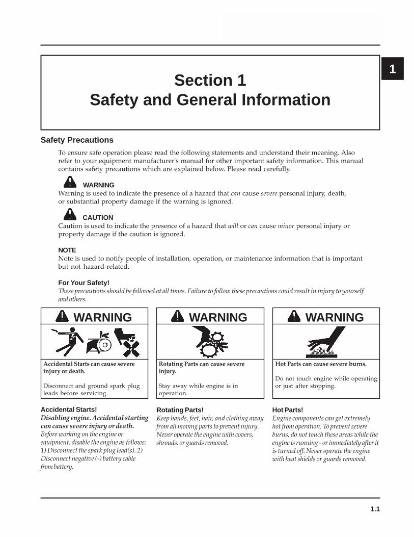
Rotating Parts can cause severeinjury.
Stay away while engine is inoperation.
WARNING
Rotating Parts!Keep hands, feet, hair, and clothing awayfrom all moving parts to prevent injury.Never operate the engine with covers,shrouds, or guards removed.
Hot Parts can cause severe burns.
Do not touch engine while operatingor just after stopping.
WARNING
Hot Parts!Engine components can get extremelyhot from operation. To prevent severeburns, do not touch these areas while theengine is running - or immediately after itis turned off. Never operate the enginewith heat shields or guards removed.
Accidental Starts can cause severeinjury or death.
Disconnect and ground spark plugleads before servicing.
WARNING
Accidental Starts!Disabling engine. Accidental startingcan cause severe injury or death.Before working on the engine orequipment, disable the engine as follows:1) Disconnect the spark plug lead(s). 2)Disconnect negative (-) battery cablefrom battery.

1.2
Section 1Safety and General Information
Carbon Monoxide can cause severenausea, fainting or death.
Avoid inhaling exhaust fumes, andnever run the engine in a closedbuilding or confined area.
WARNING WARNING
Electrical Shock can cause injury.
Do not touch wires while engine isrunning.
CAUTION
Uncoiling Spring can cause severeinjury.
Wear safety goggles or faceprotection when servicingretractable starter.
WARNING
Explosive Gas can cause fires andsevere acid burns.
Charge battery only in a wellventilated area. Keep sources ofignition away.
Lethal Exhaust Gases!Engine exhaust gases contain poisonouscarbon monoxide. Carbon monoxide isodorless, colorless, and can cause death ifinhaled. Avoid inhaling exhaust fumes,and never run the engine in a closedbuilding or confined area.
Spring Under Tension!Retractable starters contain a powerful,recoil spring that is under tension.Always wear safety goggles whenservicing retractable starters andcarefully follow instructions in the"Retractable Starter" Section 7 forrelieving spring tension.
Explosive Gas!Batteries produce explosive hydrogen gaswhile being charged. To prevent a fire orexplosion, charge batteries only in wellventilated areas. Keep sparks, openflames, and other sources of ignitionaway from the battery at all times. Keepbatteries out of the reach of children.Remove all jewelry when servicingbatteries.
Before disconnecting the negative (-)ground cable, make sure all switches areOFF. If ON, a spark will occur at theground cable terminal which could causean explosion if hydrogen gas or gasolinevapors are present.
Explosive Fuel can cause fires andsevere burns.
WARNING
Explosive Fuel!Gasoline is extremely flammable and itsvapors can explode if ignited. Storegasoline only in approved containers, inwell ventilated, unoccupied buildings,away from sparks or flames. Do not fillthe fuel tank while the engine is hot orrunning, since spilled fuel could ignite ifit comes in contact with hot parts orsparks from ignition. Do not start theengine near spilled fuel. Never usegasoline as a cleaning agent.
Cleaning Solvents can cause severeinjury or death.
Use only in well ventilated areasaway from ignition sources.
WARNING
Flammable Solvents!Carburetor cleaners and solvents areextremely flammable. Keep sparks,flames, and other sources of ignitionaway from the area. Follow the cleanermanufacturer’s warnings andinstructions on its proper and safe use.Never use gasoline as a cleaning agent.
Electrical Shock!Never touch electrical wires orcomponents while the engine is running.They can be sources of electrical shock.
Do not fill the fuel tank while theengine is hot or running.
1.3
Section 1Safety and General Information
1
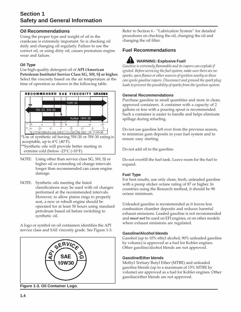
A. Model No.
Version CodeS = Electric Start
C H 18 S
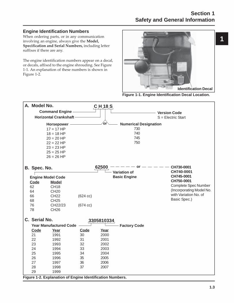
Engine Identification NumbersWhen ordering parts, or in any communicationinvolving an engine, always give the Model,Specification and Serial Numbers, including lettersuffixes if there are any.
The engine identification numbers appear on a decal,or decals, affixed to the engine shrouding. See Figure1-1. An explanation of these numbers is shown inFigure 1-2.
Figure 1-1. Engine Identification Decal Location.
Variation ofBasic Engine
B. Spec. No. 62500
Command EngineHorizontal Crankshaft
Horsepower17 = 17 HP18 = 18 HP20 = 20 HP22 = 22 HP23 = 23 HP25 = 25 HP26 = 26 HP
Numerical Designation730740745750
or
Engine Model CodeCode Model62 CH1864 CH2066 CH22 (624 cc)68 CH2576 CH22/23 (674 cc)78 CH26
CH730-0001CH740-0001CH745-0001CH750-0001Complete Spec Number(Incorporating Model No.with Variation No. ofBasic Spec.)
or
Figure 1-2. Explanation of Engine Identification Numbers.
C. Serial No.Year Manufactured CodeCode Year21 199122 199223 199324 199425 199526 199627 199728 199829 1999
Factory Code3305810334
Code Year30 200031 200132 200233 200334 200435 200536 200637 2007
Identification Decal
1.4
Section 1Safety and General Information
Oil RecommendationsUsing the proper type and weight of oil in thecrankcase is extremely important. So is checking oildaily and changing oil regularly. Failure to use thecorrect oil, or using dirty oil, causes premature enginewear and failure.
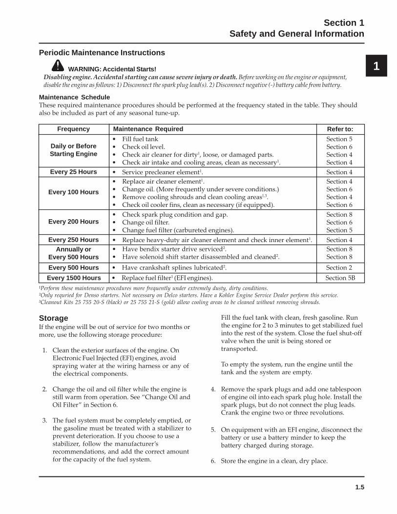
Oil TypeUse high-quality detergent oil of API (AmericanPetroleum Institute) Service Class SG, SH, SJ or higher.Select the viscosity based on the air temperature at thetime of operation as shown in the following table.
Refer to Section 6 - “Lubrication System” for detailedprocedures on checking the oil, changing the oil andchanging the oil filter.
Fuel Recommendations
WARNING: Explosive Fuel!Gasoline is extremely flammable and its vapors can explode ifignited. Before servicing the fuel system, make sure there are nosparks, open flames or other sources of ignition nearby as thesecan ignite gasoline vapors. Disconnect and ground the spark plugleads to prevent the possibility of sparks from the ignition system.
General RecommendationsPurchase gasoline in small quantities and store in clean,approved containers. A container with a capacity of 2gallons or less with a pouring spout is recommended.Such a container is easier to handle and helps eliminatespillage during refueling.
Do not use gasoline left over from the previous season,to minimize gum deposits in your fuel system and toensure easy starting.
Do not add oil to the gasoline.
Do not overfill the fuel tank. Leave room for the fuel toexpand.
Fuel TypeFor best results, use only clean, fresh, unleaded gasolinewith a pump sticker octane rating of 87 or higher. Incountries using the Research method, it should be 90octane minimum.
Unleaded gasoline is recommended as it leaves lesscombustion chamber deposits and reduces harmfulexhaust emissions. Leaded gasoline is not recommendedand must not be used on EFI engines, or on other modelswhere exhaust emissions are regulated.
Gasoline/Alcohol blendsGasohol (up to 10% ethyl alcohol, 90% unleaded gasolineby volume) is approved as a fuel for Kohler engines.Other gasoline/alcohol blends are not approved.
Gasoline/Ether blendsMethyl Tertiary Butyl Ether (MTBE) and unleadedgasoline blends (up to a maximum of 15% MTBE byvolume) are approved as a fuel for Kohler engines. Othergasoline/ether blends are not approved.
NOTE: Using other than service class SG, SH, SJ orhigher oil or extending oil change intervalslonger than recommended can cause enginedamage.
NOTE: Synthetic oils meeting the listedclassifications may be used with oil changesperformed at the recommended intervals.However, to allow piston rings to properlyseat, a new or rebuilt engine should beoperated for at least 50 hours using standardpetroleum based oil before switching tosynthetic oil.
A logo or symbol on oil containers identifies the APIservice class and SAE viscosity grade. See Figure 1-3.
Figure 1-3. Oil Container Logo.
*
*Use of synthetic oil having 5W-20 or 5W-30 rating is acceptable, up to 4°C (40°F).**Synthetic oils will provide better starting in
extreme cold (below -23°C (-10°F).
**
1.5
Section 1Safety and General Information
1Periodic Maintenance Instructions
WARNING: Accidental Starts!Disabling engine. Accidental starting can cause severe injury or death. Before working on the engine or equipment,disable the engine as follows: 1) Disconnect the spark plug lead(s). 2) Disconnect negative (-) battery cable from battery.
Maintenance ScheduleThese required maintenance procedures should be performed at the frequency stated in the table. They shouldalso be included as part of any seasonal tune-up.
StorageIf the engine will be out of service for two months ormore, use the following storage procedure:
1. Clean the exterior surfaces of the engine. OnElectronic Fuel Injected (EFI) engines, avoidspraying water at the wiring harness or any ofthe electrical components.
2. Change the oil and oil filter while the engine isstill warm from operation. See “Change Oil andOil Filter” in Section 6.
3. The fuel system must be completely emptied, orthe gasoline must be treated with a stabilizer toprevent deterioration. If you choose to use astabilizer, follow the manufacturer’srecommendations, and add the correct amountfor the capacity of the fuel system.
Fill the fuel tank with clean, fresh gasoline. Runthe engine for 2 to 3 minutes to get stabilized fuelinto the rest of the system. Close the fuel shut-offvalve when the unit is being stored ortransported.
To empty the system, run the engine until thetank and the system are empty.
4. Remove the spark plugs and add one tablespoonof engine oil into each spark plug hole. Install thespark plugs, but do not connect the plug leads.Crank the engine two or three revolutions.
5. On equipment with an EFI engine, disconnect thebattery or use a battery minder to keep thebattery charged during storage.
6. Store the engine in a clean, dry place.
• Replace fuel filter1 (EFI engines). Section 5B
Daily or BeforeStarting Engine
Maintenance RequiredFrequency
• Fill fuel tank Section 5• Check oil level. Section 6• Check air cleaner for dirty1, loose, or damaged parts. Section 4• Check air intake and cooling areas, clean as necessary1. Section 4
• Service precleaner element1. Section 4Every 25 Hours• Replace air cleaner element1. Section 4• Change oil. (More frequently under severe conditions.) Section 6• Remove cooling shrouds and clean cooling areas1,3. Section 4• Check oil cooler fins, clean as necessary (if equipped). Section 6
• Check spark plug condition and gap. Section 8• Change oil filter. Section 6• Change fuel filter (carbureted engines). Section 5
Annually orEvery 500 Hours
• Have bendix starter drive serviced2. Section 8• Have solenoid shift starter disassembled and cleaned2. Section 8
Every 100 Hours
Every 200 Hours
Every 1500 Hours
• Have crankshaft splines lubricated2. Section 2Every 500 Hours
Every 250 Hours • Replace heavy-duty air cleaner element and check inner element1. Section 4
¹Perform these maintenance procedures more frequently under extremely dusty, dirty conditions.²Only requried for Denso starters. Not necessary on Delco starters. Have a Kohler Engine Service Dealer perform this service.³Cleanout Kits 25 755 20-S (black) or 25 755 21-S (gold) allow cooling areas to be cleaned without removing shrouds.
Refer to:

1.6
Section 1Safety and General Information
Figure 1-4. Typical Engine Dimensions CH Series with Standard Flat Air Cleaner.
Dimensions in millimeters.Inch equivalents shown in [ ].

1.7
Section 1Safety and General Information
1
Figure 1-5. Typical Engine Dimensions CH EFI Series with Heavy-Duty Air Cleaner.
Dimensions in millimeters.Inch equivalents shown in [ ].
1.8
Section 1Safety and General Information
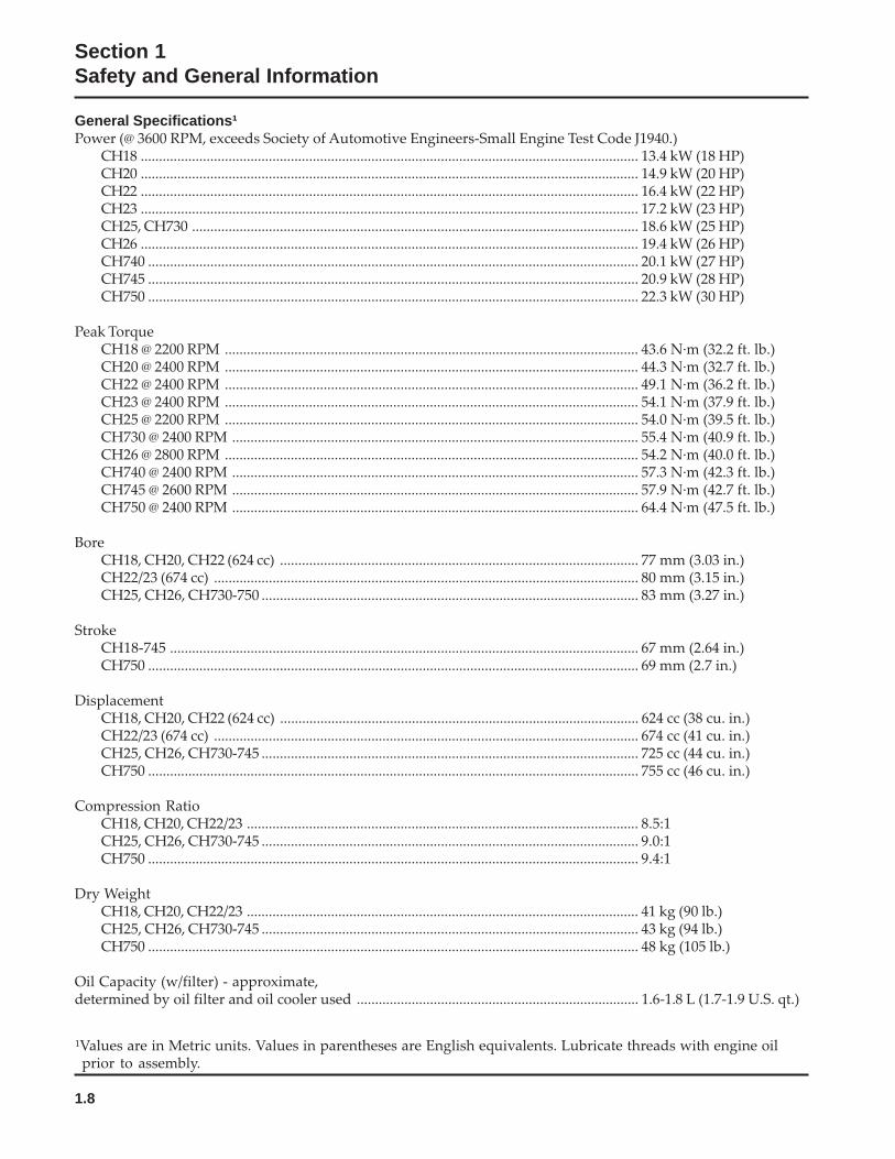
General Specifications¹Power (@ 3600 RPM, exceeds Society of Automotive Engineers-Small Engine Test Code J1940.)
CH18 ........................................................................................................................................ 13.4 kW (18 HP)CH20 ........................................................................................................................................ 14.9 kW (20 HP)CH22 ........................................................................................................................................ 16.4 kW (22 HP)CH23 ........................................................................................................................................ 17.2 kW (23 HP)CH25, CH730 .......................................................................................................................... 18.6 kW (25 HP)CH26 ........................................................................................................................................ 19.4 kW (26 HP)CH740 ...................................................................................................................................... 20.1 kW (27 HP)CH745 ...................................................................................................................................... 20.9 kW (28 HP)CH750 ...................................................................................................................................... 22.3 kW (30 HP)
Peak TorqueCH18 @ 2200 RPM ................................................................................................................. 43.6 N·m (32.2 ft. lb.)CH20 @ 2400 RPM ................................................................................................................. 44.3 N·m (32.7 ft. lb.)CH22 @ 2400 RPM ................................................................................................................. 49.1 N·m (36.2 ft. lb.)CH23 @ 2400 RPM ................................................................................................................. 54.1 N·m (37.9 ft. lb.)CH25 @ 2200 RPM ................................................................................................................. 54.0 N·m (39.5 ft. lb.)CH730 @ 2400 RPM ............................................................................................................... 55.4 N·m (40.9 ft. lb.)CH26 @ 2800 RPM ................................................................................................................. 54.2 N·m (40.0 ft. lb.)CH740 @ 2400 RPM ............................................................................................................... 57.3 N·m (42.3 ft. lb.)CH745 @ 2600 RPM ............................................................................................................... 57.9 N·m (42.7 ft. lb.)CH750 @ 2400 RPM ............................................................................................................... 64.4 N·m (47.5 ft. lb.)
BoreCH18, CH20, CH22 (624 cc) .................................................................................................. 77 mm (3.03 in.)CH22/23 (674 cc) .................................................................................................................... 80 mm (3.15 in.)CH25, CH26, CH730-750 ....................................................................................................... 83 mm (3.27 in.)
StrokeCH18-745 ................................................................................................................................ 67 mm (2.64 in.)CH750 ...................................................................................................................................... 69 mm (2.7 in.)
DisplacementCH18, CH20, CH22 (624 cc) .................................................................................................. 624 cc (38 cu. in.)CH22/23 (674 cc) .................................................................................................................... 674 cc (41 cu. in.)CH25, CH26, CH730-745 ....................................................................................................... 725 cc (44 cu. in.)CH750 ...................................................................................................................................... 755 cc (46 cu. in.)
Compression RatioCH18, CH20, CH22/23 ........................................................................................................... 8.5:1CH25, CH26, CH730-745 ....................................................................................................... 9.0:1CH750 ...................................................................................................................................... 9.4:1
Dry WeightCH18, CH20, CH22/23 ........................................................................................................... 41 kg (90 lb.)CH25, CH26, CH730-745 ....................................................................................................... 43 kg (94 lb.)CH750 ...................................................................................................................................... 48 kg (105 lb.)
Oil Capacity (w/filter) - approximate,determined by oil filter and oil cooler used ............................................................................. 1.6-1.8 L (1.7-1.9 U.S. qt.)
¹Values are in Metric units. Values in parentheses are English equivalents. Lubricate threads with engine oilprior to assembly.
1.9
Section 1Safety and General Information
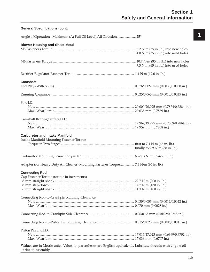
1General Specifications¹ cont.
Angle of Operation - Maximum (At Full Oil Level) All Directions ................... 25°
Blower Housing and Sheet MetalM5 Fasteners Torque ................................................................................................ 6.2 N·m (55 in. lb.) into new holes
4.0 N·m (35 in. lb.) into used holes
M6 Fasteners Torque ................................................................................................ 10.7 N·m (95 in. lb.) into new holes7.3 N·m (65 in. lb.) into used holes
Rectifier-Regulator Fastener Torque ................................................................... 1.4 N·m (12.6 in. lb.)
CamshaftEnd Play (With Shim) ............................................................................................ 0.076/0.127 mm (0.0030/0.0050 in.)
Running Clearance ................................................................................................. 0.025/0.063 mm (0.0010/0.0025 in.)
Bore I.D.New .................................................................................................................. 20.000/20.025 mm (0.7874/0.7884 in.)Max. Wear Limit ............................................................................................. 20.038 mm (0.7889 in.)
Camshaft Bearing Surface O.D.New .................................................................................................................. 19.962/19.975 mm (0.7859/0.7864 in.)Max. Wear Limit ............................................................................................. 19.959 mm (0.7858 in.)
Carburetor and Intake ManifoldIntake Manifold Mounting Fastener Torque
Torque in Two Stages ..................................................................................... first to 7.4 N·m (66 in. lb.)finally to 9.9 N·m (88 in. lb.)
Carburetor Mounting Screw Torque M6 ............................................................ 6.2-7.3 N·m (55-65 in. lb.)
Adapter (for Heavy Duty Air Cleaner) Mounting Fastener Torque ................ 7.3 N·m (65 in. lb.)
Connecting RodCap Fastener Torque (torque in increments)
8 mm straight shank ............................................................................................ 22.7 N·m (200 in. lb.)8 mm step-down .................................................................................................. 14.7 N·m (130 in. lb.)6 mm straight shank ............................................................................................ 11.3 N·m (100 in. lb.)
Connecting Rod-to-Crankpin Running ClearanceNew .................................................................................................................. 0.030/0.055 mm (0.0012/0.0022 in.)Max. Wear Limit ............................................................................................. 0.070 mm (0.0028 in.)
Connecting Rod-to-Crankpin Side Clearance .................................................... 0.26/0.63 mm (0.0102/0.0248 in.)
Connecting Rod-to-Piston Pin Running Clearance ........................................... 0.015/0.028 mm (0.0006/0.0011 in.)
Piston Pin End I.D.New .................................................................................................................. 17.015/17.023 mm (0.6699/0.6702 in.)Max. Wear Limit ............................................................................................. 17.036 mm (0.6707 in.)
¹Values are in Metric units. Values in parentheses are English equivalents. Lubricate threads with engine oilprior to assembly.
1.10
Section 1Safety and General Information
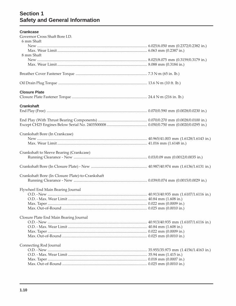
CrankcaseGovernor Cross Shaft Bore I.D.
6 mm ShaftNew .................................................................................................................. 6.025/6.050 mm (0.2372/0.2382 in.)Max. Wear Limit ............................................................................................. 6.063 mm (0.2387 in.)
8 mm ShaftNew .................................................................................................................. 8.025/8.075 mm (0.3159/0.3179 in.)Max. Wear Limit ............................................................................................. 8.088 mm (0.3184 in.)
Breather Cover Fastener Torque .......................................................................... 7.3 N·m (65 in. lb.)
Oil Drain Plug Torque ............................................................................................ 13.6 N·m (10 ft. lb.)
Closure PlateClosure Plate Fastener Torque .............................................................................. 24.4 N·m (216 in. lb.)
CrankshaftEnd Play (Free) ........................................................................................................ 0.070/0.590 mm (0.0028/0.0230 in.)
End Play (With Thrust Bearing Components) ................................................... 0.070/0.270 mm (0.0028/0.0100 in.)Except CH25 Engines Below Serial No. 2403500008 .......................................... 0.050/0.750 mm (0.0020/0.0295 in.)
Crankshaft Bore (In Crankcase)New .................................................................................................................. 40.965/41.003 mm (1.6128/1.6143 in.)Max. Wear Limit ............................................................................................. 41.016 mm (1.6148 in.)
Crankshaft to Sleeve Bearing (Crankcase)Running Clearance - New ............................................................................ 0.03/0.09 mm (0.0012/0.0035 in.)
Crankshaft Bore (In Closure Plate) - New .......................................................... 40.987/40.974 mm (1.6136/1.6131 in.)
Crankshaft Bore (In Closure Plate)-to-CrankshaftRunning Clearance - New ............................................................................ 0.039/0.074 mm (0.0015/0.0029 in.)
Flywheel End Main Bearing JournalO.D. - New ....................................................................................................... 40.913/40.935 mm (1.6107/1.6116 in.)O.D. - Max. Wear Limit .................................................................................. 40.84 mm (1.608 in.)Max. Taper ....................................................................................................... 0.022 mm (0.0009 in.)Max. Out-of-Round ........................................................................................ 0.025 mm (0.0010 in.)
Closure Plate End Main Bearing JournalO.D. - New ....................................................................................................... 40.913/40.935 mm (1.6107/1.6116 in.)O.D. - Max. Wear Limit .................................................................................. 40.84 mm (1.608 in.)Max. Taper ....................................................................................................... 0.022 mm (0.0009 in.)Max. Out-of-Round ........................................................................................ 0.025 mm (0.0010 in.)
Connecting Rod JournalO.D. - New ....................................................................................................... 35.955/35.973 mm (1.4156/1.4163 in.)O.D. - Max. Wear Limit .................................................................................. 35.94 mm (1.415 in.)Max. Taper ....................................................................................................... 0.018 mm (0.0007 in.)Max. Out-of-Round ........................................................................................ 0.025 mm (0.0010 in.)
1.11
Section 1Safety and General Information
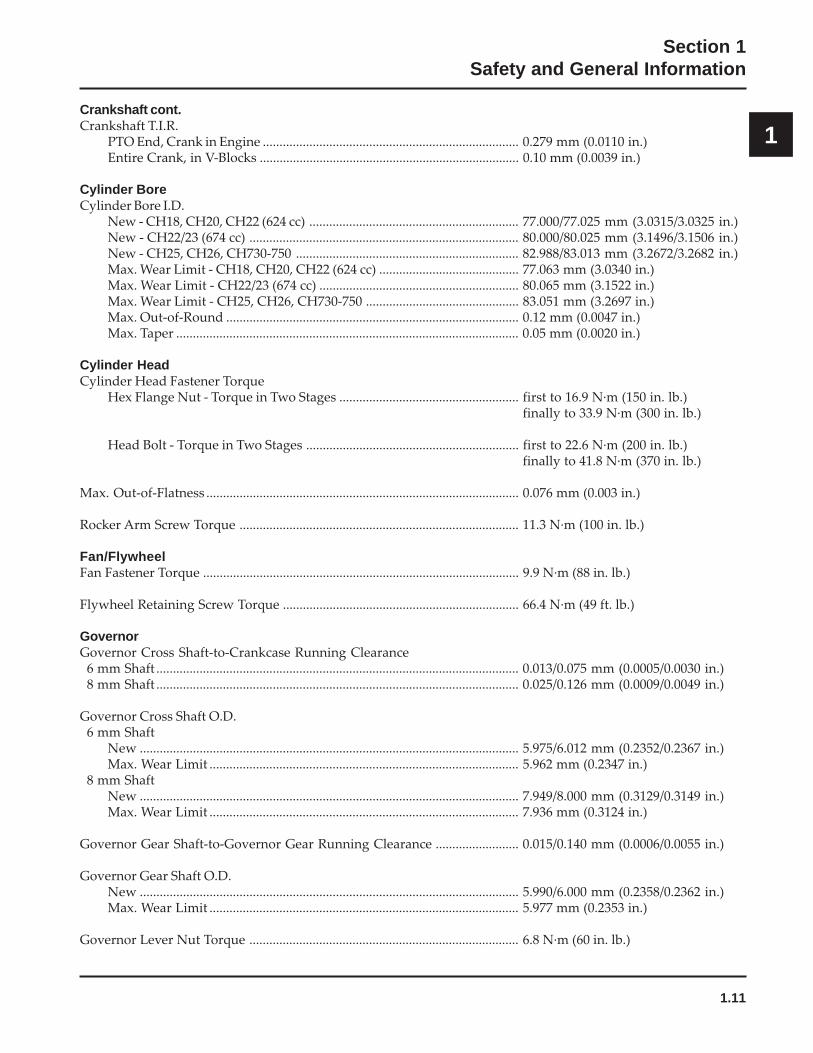
1Crankshaft cont.Crankshaft T.I.R.
PTO End, Crank in Engine ............................................................................. 0.279 mm (0.0110 in.)Entire Crank, in V-Blocks .............................................................................. 0.10 mm (0.0039 in.)
Cylinder BoreCylinder Bore I.D.
New - CH18, CH20, CH22 (624 cc) ............................................................... 77.000/77.025 mm (3.0315/3.0325 in.)New - CH22/23 (674 cc) ................................................................................. 80.000/80.025 mm (3.1496/3.1506 in.)New - CH25, CH26, CH730-750 ................................................................... 82.988/83.013 mm (3.2672/3.2682 in.)Max. Wear Limit - CH18, CH20, CH22 (624 cc) .......................................... 77.063 mm (3.0340 in.)Max. Wear Limit - CH22/23 (674 cc) ............................................................ 80.065 mm (3.1522 in.)Max. Wear Limit - CH25, CH26, CH730-750 .............................................. 83.051 mm (3.2697 in.)Max. Out-of-Round ........................................................................................ 0.12 mm (0.0047 in.)Max. Taper ....................................................................................................... 0.05 mm (0.0020 in.)
Cylinder HeadCylinder Head Fastener Torque
Hex Flange Nut - Torque in Two Stages ...................................................... first to 16.9 N·m (150 in. lb.)finally to 33.9 N·m (300 in. lb.)
Head Bolt - Torque in Two Stages ................................................................ first to 22.6 N·m (200 in. lb.)finally to 41.8 N·m (370 in. lb.)
Max. Out-of-Flatness .............................................................................................. 0.076 mm (0.003 in.)
Rocker Arm Screw Torque .................................................................................... 11.3 N·m (100 in. lb.)
Fan/FlywheelFan Fastener Torque ............................................................................................... 9.9 N·m (88 in. lb.)
Flywheel Retaining Screw Torque ....................................................................... 66.4 N·m (49 ft. lb.)
GovernorGovernor Cross Shaft-to-Crankcase Running Clearance
6 mm Shaft ............................................................................................................. 0.013/0.075 mm (0.0005/0.0030 in.)8 mm Shaft ............................................................................................................. 0.025/0.126 mm (0.0009/0.0049 in.)
Governor Cross Shaft O.D.6 mm Shaft
New .................................................................................................................. 5.975/6.012 mm (0.2352/0.2367 in.)Max. Wear Limit ............................................................................................. 5.962 mm (0.2347 in.)
8 mm ShaftNew .................................................................................................................. 7.949/8.000 mm (0.3129/0.3149 in.)Max. Wear Limit ............................................................................................. 7.936 mm (0.3124 in.)
Governor Gear Shaft-to-Governor Gear Running Clearance ......................... 0.015/0.140 mm (0.0006/0.0055 in.)
Governor Gear Shaft O.D.New .................................................................................................................. 5.990/6.000 mm (0.2358/0.2362 in.)Max. Wear Limit ............................................................................................. 5.977 mm (0.2353 in.)
Governor Lever Nut Torque ................................................................................. 6.8 N·m (60 in. lb.)
1.12
Section 1Safety and General Information
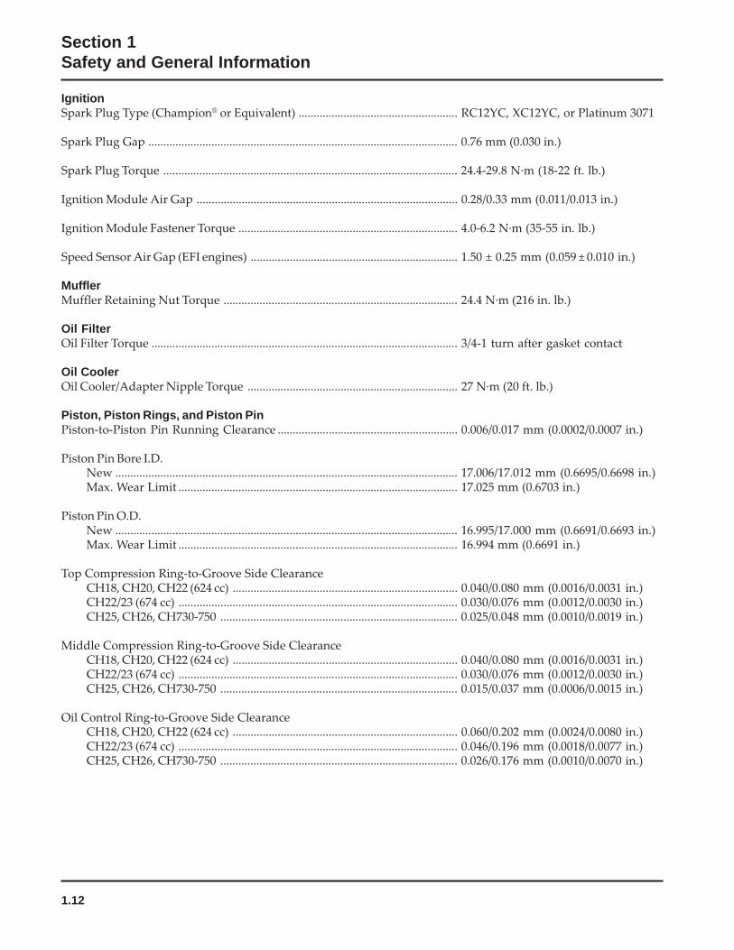
IgnitionSpark Plug Type (Champion® or Equivalent) ..................................................... RC12YC, XC12YC, or Platinum 3071
Spark Plug Gap ....................................................................................................... 0.76 mm (0.030 in.)
Spark Plug Torque .................................................................................................. 24.4-29.8 N·m (18-22 ft. lb.)
Ignition Module Air Gap ....................................................................................... 0.28/0.33 mm (0.011/0.013 in.)
Ignition Module Fastener Torque ......................................................................... 4.0-6.2 N·m (35-55 in. lb.)
Speed Sensor Air Gap (EFI engines) ..................................................................... 1.50 ± 0.25 mm (0.059 ± 0.010 in.)
MufflerMuffler Retaining Nut Torque .............................................................................. 24.4 N·m (216 in. lb.)
Oil FilterOil Filter Torque ...................................................................................................... 3/4-1 turn after gasket contact
Oil CoolerOil Cooler/Adapter Nipple Torque ...................................................................... 27 N·m (20 ft. lb.)
Piston, Piston Rings, and Piston PinPiston-to-Piston Pin Running Clearance ............................................................ 0.006/0.017 mm (0.0002/0.0007 in.)
Piston Pin Bore I.D.New .................................................................................................................. 17.006/17.012 mm (0.6695/0.6698 in.)Max. Wear Limit ............................................................................................. 17.025 mm (0.6703 in.)
Piston Pin O.D.New .................................................................................................................. 16.995/17.000 mm (0.6691/0.6693 in.)Max. Wear Limit ............................................................................................. 16.994 mm (0.6691 in.)
Top Compression Ring-to-Groove Side ClearanceCH18, CH20, CH22 (624 cc) ........................................................................... 0.040/0.080 mm (0.0016/0.0031 in.)CH22/23 (674 cc) ............................................................................................. 0.030/0.076 mm (0.0012/0.0030 in.)CH25, CH26, CH730-750 ............................................................................... 0.025/0.048 mm (0.0010/0.0019 in.)
Middle Compression Ring-to-Groove Side ClearanceCH18, CH20, CH22 (624 cc) ........................................................................... 0.040/0.080 mm (0.0016/0.0031 in.)CH22/23 (674 cc) ............................................................................................. 0.030/0.076 mm (0.0012/0.0030 in.)CH25, CH26, CH730-750 ............................................................................... 0.015/0.037 mm (0.0006/0.0015 in.)
Oil Control Ring-to-Groove Side ClearanceCH18, CH20, CH22 (624 cc) ........................................................................... 0.060/0.202 mm (0.0024/0.0080 in.)CH22/23 (674 cc) ............................................................................................. 0.046/0.196 mm (0.0018/0.0077 in.)CH25, CH26, CH730-750 ............................................................................... 0.026/0.176 mm (0.0010/0.0070 in.)
1.13
Section 1Safety and General Information
1
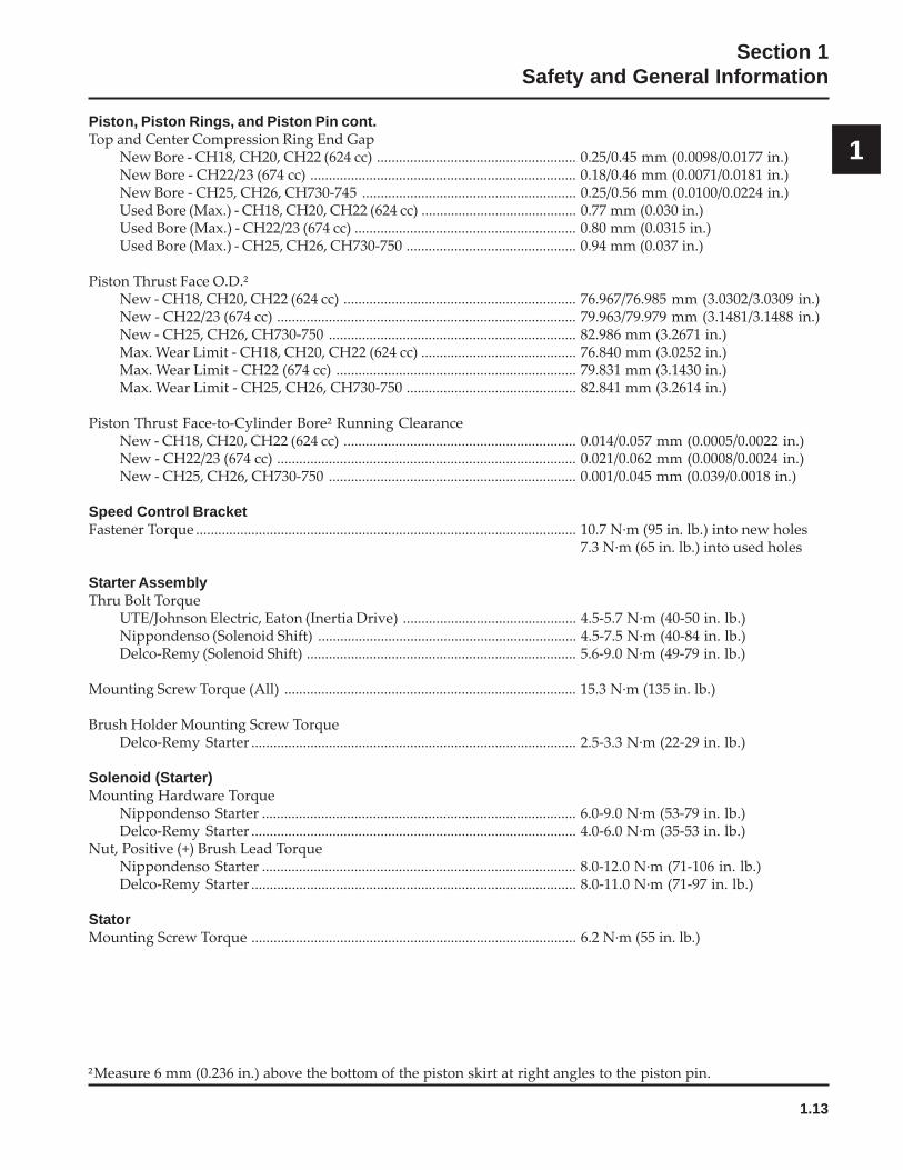
²Measure 6 mm (0.236 in.) above the bottom of the piston skirt at right angles to the piston pin.
Piston, Piston Rings, and Piston Pin cont.Top and Center Compression Ring End Gap
New Bore - CH18, CH20, CH22 (624 cc) ...................................................... 0.25/0.45 mm (0.0098/0.0177 in.)New Bore - CH22/23 (674 cc) ........................................................................ 0.18/0.46 mm (0.0071/0.0181 in.)New Bore - CH25, CH26, CH730-745 .......................................................... 0.25/0.56 mm (0.0100/0.0224 in.)Used Bore (Max.) - CH18, CH20, CH22 (624 cc) .......................................... 0.77 mm (0.030 in.)Used Bore (Max.) - CH22/23 (674 cc) ............................................................ 0.80 mm (0.0315 in.)Used Bore (Max.) - CH25, CH26, CH730-750 .............................................. 0.94 mm (0.037 in.)
Piston Thrust Face O.D.²New - CH18, CH20, CH22 (624 cc) ............................................................... 76.967/76.985 mm (3.0302/3.0309 in.)New - CH22/23 (674 cc) ................................................................................. 79.963/79.979 mm (3.1481/3.1488 in.)New - CH25, CH26, CH730-750 ................................................................... 82.986 mm (3.2671 in.)Max. Wear Limit - CH18, CH20, CH22 (624 cc) .......................................... 76.840 mm (3.0252 in.)Max. Wear Limit - CH22 (674 cc) ................................................................. 79.831 mm (3.1430 in.)Max. Wear Limit - CH25, CH26, CH730-750 .............................................. 82.841 mm (3.2614 in.)
Piston Thrust Face-to-Cylinder Bore² Running ClearanceNew - CH18, CH20, CH22 (624 cc) ............................................................... 0.014/0.057 mm (0.0005/0.0022 in.)New - CH22/23 (674 cc) ................................................................................. 0.021/0.062 mm (0.0008/0.0024 in.)New - CH25, CH26, CH730-750 ................................................................... 0.001/0.045 mm (0.039/0.0018 in.)
Speed Control BracketFastener Torque ....................................................................................................... 10.7 N·m (95 in. lb.) into new holes
7.3 N·m (65 in. lb.) into used holes
Starter AssemblyThru Bolt Torque
UTE/Johnson Electric, Eaton (Inertia Drive) ............................................... 4.5-5.7 N·m (40-50 in. lb.)Nippondenso (Solenoid Shift) ...................................................................... 4.5-7.5 N·m (40-84 in. lb.)Delco-Remy (Solenoid Shift) ......................................................................... 5.6-9.0 N·m (49-79 in. lb.)
Mounting Screw Torque (All) ............................................................................... 15.3 N·m (135 in. lb.)
Brush Holder Mounting Screw TorqueDelco-Remy Starter ........................................................................................ 2.5-3.3 N·m (22-29 in. lb.)
Solenoid (Starter)Mounting Hardware Torque
Nippondenso Starter ..................................................................................... 6.0-9.0 N·m (53-79 in. lb.)Delco-Remy Starter ........................................................................................ 4.0-6.0 N·m (35-53 in. lb.)
Nut, Positive (+) Brush Lead TorqueNippondenso Starter ..................................................................................... 8.0-12.0 N·m (71-106 in. lb.)Delco-Remy Starter ........................................................................................ 8.0-11.0 N·m (71-97 in. lb.)
StatorMounting Screw Torque ........................................................................................ 6.2 N·m (55 in. lb.)
1.14
Section 1Safety and General Information
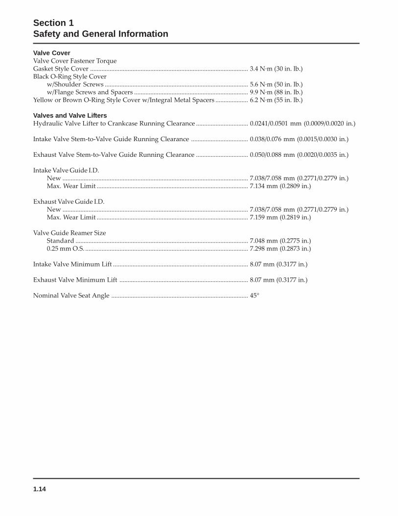
Valve CoverValve Cover Fastener TorqueGasket Style Cover ................................................................................................. 3.4 N·m (30 in. lb.)Black O-Ring Style Cover
w/Shoulder Screws ........................................................................................ 5.6 N·m (50 in. lb.)w/Flange Screws and Spacers ...................................................................... 9.9 N·m (88 in. lb.)
Yellow or Brown O-Ring Style Cover w/Integral Metal Spacers .................... 6.2 N·m (55 in. lb.)
Valves and Valve LiftersHydraulic Valve Lifter to Crankcase Running Clearance ................................ 0.0241/0.0501 mm (0.0009/0.0020 in.)
Intake Valve Stem-to-Valve Guide Running Clearance ................................... 0.038/0.076 mm (0.0015/0.0030 in.)
Exhaust Valve Stem-to-Valve Guide Running Clearance ................................ 0.050/0.088 mm (0.0020/0.0035 in.)
Intake Valve Guide I.D.New .................................................................................................................. 7.038/7.058 mm (0.2771/0.2779 in.)Max. Wear Limit ............................................................................................. 7.134 mm (0.2809 in.)
Exhaust Valve Guide I.D.New .................................................................................................................. 7.038/7.058 mm (0.2771/0.2779 in.)Max. Wear Limit ............................................................................................. 7.159 mm (0.2819 in.)
Valve Guide Reamer SizeStandard .......................................................................................................... 7.048 mm (0.2775 in.)0.25 mm O.S. .................................................................................................... 7.298 mm (0.2873 in.)
Intake Valve Minimum Lift ................................................................................... 8.07 mm (0.3177 in.)
Exhaust Valve Minimum Lift ............................................................................... 8.07 mm (0.3177 in.)
Nominal Valve Seat Angle .................................................................................... 45°
1.15
Section 1Safety and General Information
1
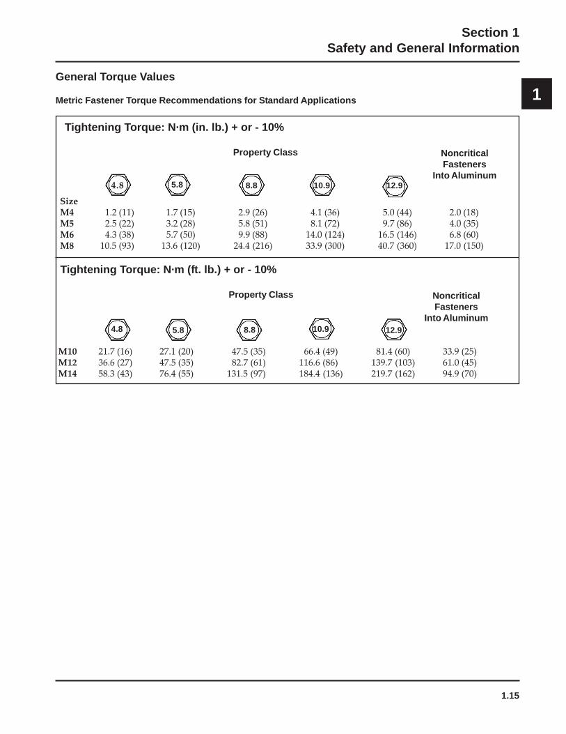
Tightening Torque: N·m (in. lb.) + or - 10%
Property Class NoncriticalFasteners
Into Aluminum
SizeM4 1.2 (11) 1.7 (15) 2.9 (26) 4.1 (36) 5.0 (44) 2.0 (18)M5 2.5 (22) 3.2 (28) 5.8 (51) 8.1 (72) 9.7 (86) 4.0 (35)M6 4.3 (38) 5.7 (50) 9.9 (88) 14.0 (124) 16.5 (146) 6.8 (60)M8 10.5 (93) 13.6 (120) 24.4 (216) 33.9 (300) 40.7 (360) 17.0 (150)
Tightening Torque: N·m (ft. lb.) + or - 10%
Property Class NoncriticalFasteners
Into Aluminum
M10 21.7 (16) 27.1 (20) 47.5 (35) 66.4 (49) 81.4 (60) 33.9 (25)M12 36.6 (27) 47.5 (35) 82.7 (61) 116.6 (86) 139.7 (103) 61.0 (45)M14 58.3 (43) 76.4 (55) 131.5 (97) 184.4 (136) 219.7 (162) 94.9 (70)
5.8 8.8 10.9 12.9
4.8 5.8 10.9 12.9
4.8
8.8
General Torque Values
Metric Fastener Torque Recommendations for Standard Applications
1.16
Section 1Safety and General Information
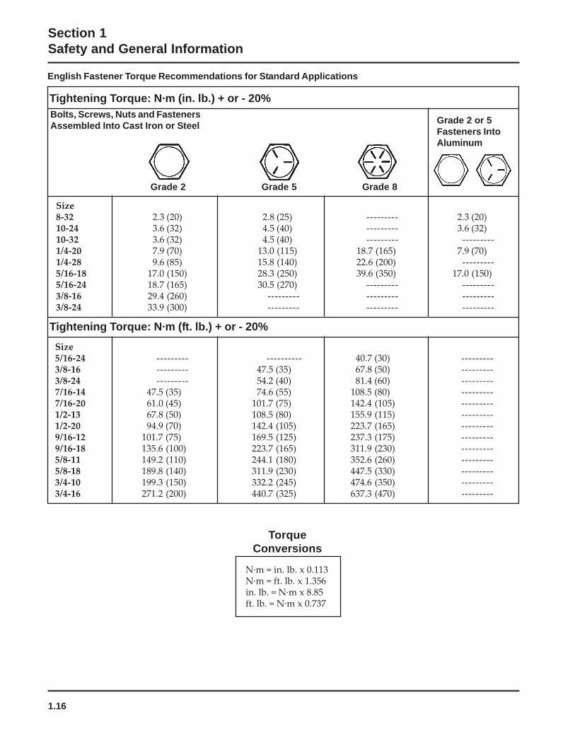
English Fastener Torque Recommendations for Standard Applications
Grade 2 or 5Fasteners IntoAluminum
Size8-32 2.3 (20) 2.8 (25) --------- 2.3 (20)10-24 3.6 (32) 4.5 (40) --------- 3.6 (32)10-32 3.6 (32) 4.5 (40) --------- ---------1/4-20 7.9 (70) 13.0 (115) 18.7 (165) 7.9 (70)1/4-28 9.6 (85) 15.8 (140) 22.6 (200) ---------5/16-18 17.0 (150) 28.3 (250) 39.6 (350) 17.0 (150)5/16-24 18.7 (165) 30.5 (270) --------- ---------3/8-16 29.4 (260) --------- --------- ---------3/8-24 33.9 (300) --------- --------- ---------
Size5/16-24 --------- ---------- 40.7 (30) ---------3/8-16 --------- 47.5 (35) 67.8 (50) ---------3/8-24 --------- 54.2 (40) 81.4 (60) ---------7/16-14 47.5 (35) 74.6 (55) 108.5 (80) ---------7/16-20 61.0 (45) 101.7 (75) 142.4 (105) ---------1/2-13 67.8 (50) 108.5 (80) 155.9 (115) ---------1/2-20 94.9 (70) 142.4 (105) 223.7 (165) ---------9/16-12 101.7 (75) 169.5 (125) 237.3 (175) ---------9/16-18 135.6 (100) 223.7 (165) 311.9 (230) ---------5/8-11 149.2 (110) 244.1 (180) 352.6 (260) ---------5/8-18 189.8 (140) 311.9 (230) 447.5 (330) ---------3/4-10 199.3 (150) 332.2 (245) 474.6 (350) ---------3/4-16 271.2 (200) 440.7 (325) 637.3 (470) ---------
Tightening Torque: N·m (ft. lb.) + or - 20%
Tightening Torque: N·m (in. lb.) + or - 20%
Grade 2 Grade 5 Grade 8
Bolts, Screws, Nuts and FastenersAssembled Into Cast Iron or Steel
N·m = in. lb. x 0.113N·m = ft. lb. x 1.356in. lb. = N·m x 8.85ft. lb. = N·m x 0.737
TorqueConversions
2.1
Section 2Tools & Aids
2Section 2
Tools & Aids
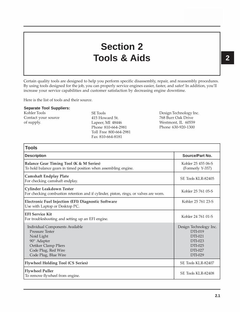
Certain quality tools are designed to help you perform specific disassembly, repair, and reassembly procedures.By using tools designed for the job, you can properly service engines easier, faster, and safer! In addition, you’llincrease your service capabilities and customer satisfaction by decreasing engine downtime.
Here is the list of tools and their source.
Separate Tool Suppliers:Kohler ToolsContact your sourceof supply.
SE Tools415 Howard St.Lapeer, MI 48446Phone 810-664-2981Toll Free 800-664-2981Fax 810-664-8181
Design Technology Inc.768 Burr Oak DriveWestmont, IL 60559Phone 630-920-1300
slooT
noitpircseD .oNtraP/ecruoS
)seireSM&K(looTgnimiTraeGecnalaB.enignegnilbmessanehwnoitisopdemitnisraegecnalabdlohoT
S-6055452relhoK)753-YylremroF(
etalPyalpdnEtfahsmaC.yalpdnetfahsmacgnikcehcroF
50428-RLKslooTES
retseTnwodkaeLrednilyC.nrowerasevlavro,sgnir,notsip,rednilycfidnanoitneternoitsubmocgnikcehcroF
S-5016752relhoK
erawtfoScitsongaiD)IFE(noitcejnIleuFcinortcelE.CPpotkseDropotpaLhtiwesU
S-3216752relhoK
IFE tiKecivreS.enigneIFEnapugnittesdnagnitoohselbuortroF
S-1016742relhoK
elbaliavAstnenopmoClaudividnIretseTerusserP
thgiLdioNretpadA°09
sreilPpmalCrekiteOeriWdeR,gulPedoCeriWeulB,gulPedoC
.cnIygolonhceTngiseD910-ITD120-ITD320-ITD520-ITD720-ITD920-ITD
)seireSSC(looTgnidloHleehwylF 70428-RLKslooTES
relluPleehwylF.enignemorfleehwylfevomeroT
80428-RLKslooTES

2.2
Section 2Tools & Aids
).tnoc(slooT
noitpircseD .oNtraP/ecruoS
hcnerWpartSleehwylF.lavomergnirudleehwylfdlohoT
90428-RLKslooTES
looTretfiLevlaVciluardyH.sretfilciluardyhllatsnidnaevomeroT
S-8316752relhoK
retseTmetsySnoitingI.DCtpecxe,smetsysllanotuptuognitsetroF
.metsysnoitingi)DC(egrahcsideviticapacnotuptuognitsetroFS-1055452relhoKS-2055442relhoK
)seireSM&K(hcnerWtesffO.stungniniaterlerrabrednilycllatsnierdnaevomeroT
01428-RLKslooTES
tiKtseTerusserPliO.erusserplioyfirevdnatsetoT
S-6016752relhoK
)tnerructlov021(retseTrotalugeR-reifitceR)tnerructlov042(retseTrotalugeR-reifitceR
.srotaluger-reifitcertsetotdesU
S-0216752relhoKS-1416752relhoK
elbaliavAstnenopmoClaudividnIssenraHtseTrotalugeRORP-SC
edoiDhtiwssenraHtseTrotalugeRlaicepS
.cnIygolonhceTngiseD130-ITD330-ITD
retseT)MAS(eludoMecnavdAkrapSKRAPS-TRAMShtiwsenigneno)MASDdnaMASA(MASehttsetoT
.™
S-0416752relhoK
)tfihSdioneloS(looTgnidloHhsurBretratS.gnicivresgnirudsehsurbdlohoT
61428-RLKslooTES
)evirDaitrenI(looTgniRgniniateRretratS.)sretratsOCSAFgnidulcxe(sgnirgniniaterevirdllatsnierdnaevomeroT
S-8116752relhoK
)sretratSllA(tiKgnicivreSretratS.sehsurbdnasgnirgniniaterevirdllatsnierdnaevomeroT
11428-RLKslooTES
elbaliavAtnenopmoClaudividnI)tfihSdioneloS(looTgnidloHhsurBretratS
61428-RLKslooTES
)evitcudnIlatigiD(retemohcaT.enignenafo)MPR(deepsgnitarepognikcehcroF
.cnIygolonhceTngiseD011-ITD
retseTerusserP/muucaV.retemonamretawaotevitanretlA
S-2216752relhoK
)seireSM&K(remaeRediuGevlaV.noitallatsniretfasediugevlavgnizisroF
31428-RLKslooTES
)CHO,dnammoC,sigeA,egaruoC(tiKecivreSediuGevlaV.sediugeulavnrowgnicivresroF
51428-RLKslooTES
2.3
Section 2Tools & Aids
2
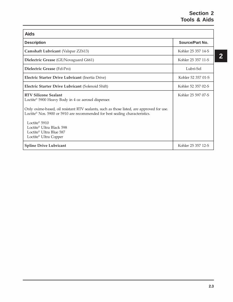
sdiA
noitpircseD .oNtraP/ecruoS
tnacirbuLtfahsmaC )316ZZrapslaV( S-4175352relhoK
esaerGcirtceleiD )166GdraugavoN/EG( S-1175352relhoK
esaerGcirtceleiD )orP-leF( leS-irbuL
tnacirbuLevirDretratScirtcelE )evirDaitrenI( S-1075325relhoK
tnacirbuLevirDretratScirtcelE )tfihSdioneloS( S-2075325relhoK
tnalaeSenociliSVTRetitcoL ® .resnepsidlosoreazo4niydoByvaeH0095
.esurofdevorppaera,detsilesohtsahcus,stnalaesVTRtnatsiserlio,desab-emixoylnOetitcoL ® .scitsiretcarahcgnilaestsebrofdednemmocerera0195ro0095.soN
etitcoL ® 0195etitcoL ® 895kcalBartlUetitcoL ® 785eulBartlUetitcoL ® reppoCartlU
S-7079552relhoK
tnacirbuLevirDenilpS S-2175352relhoK
2.4
Section 2Tools & Aids
Special Tools You Can Make
Flywheel Holding ToolA flywheel holding tool can be made out of an oldjunk flywheel ring gear as shown in Figure 2-1, andused in place of a strap wrench.
1. Using an abrasive cut-off wheel, cut out a sixtooth segment of the ring gear as shown.
2. Grind off any burrs or sharp edges.
3. Invert the segment and place it between theignition bosses on the crankcase so that the toolteeth engage the flywheel ring gear teeth. Thebosses will lock the tool and flywheel inposition for loosening, tightening or removingwith a puller.
Figure 2-1. Flywheel Holding Tool.
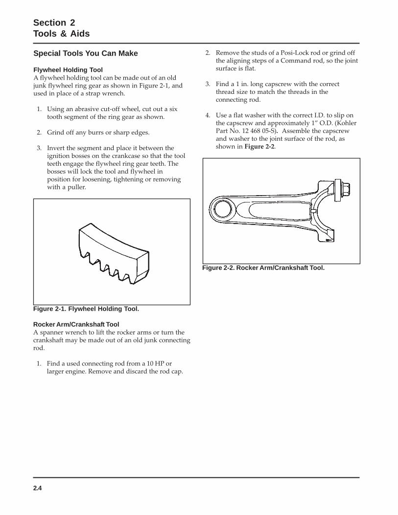
Rocker Arm/Crankshaft ToolA spanner wrench to lift the rocker arms or turn thecrankshaft may be made out of an old junk connectingrod.
1. Find a used connecting rod from a 10 HP orlarger engine. Remove and discard the rod cap.
2. Remove the studs of a Posi-Lock rod or grind offthe aligning steps of a Command rod, so the jointsurface is flat.
3. Find a 1 in. long capscrew with the correctthread size to match the threads in theconnecting rod.
4. Use a flat washer with the correct I.D. to slip onthe capscrew and approximately 1” O.D. (KohlerPart No. 12 468 05-S). Assemble the capscrewand washer to the joint surface of the rod, asshown in Figure 2-2.
Figure 2-2. Rocker Arm/Crankshaft Tool.

3.1
Section 3Troubleshooting
3
Section 3Troubleshooting
Troubleshooting GuideWhen troubles occur, be sure to check the simplecauses which, at first, may seem too obvious to beconsidered. For example, a starting problem could becaused by an empty fuel tank.
Some general common causes of engine troubles arelisted below. Use these to locate the causing factors.Refer to the specific section(s) within this servicemanual for more detailed information.
Engine Cranks But Will Not Start1. Empty fuel tank.2. Fuel shut-off valve closed.3. Poor fuel, dirt or water in the fuel system.4. Clogged fuel line.5. Spark plug lead(s) disconnected.6. Key switch or kill switch in “off” position.7. Faulty spark plugs.8. Faulty ignition module(s).9. SMART-SPARK™ malfunction (applicable models).
10. Carburetor solenoid malfunction.11. Diode in wiring harness failed in open circuit
mode.12. Vacuum fuel pump malfunction, or oil in vacuum
hose.13. Vacuum hose to fuel pump leaking/cracked.14. Battery connected backwards.15. Safety interlock system engaged.
Engine Starts But Does Not Keep Running1. Restricted fuel tank cap vent.2. Poor fuel, dirt or water in the fuel system.3. Faulty or misadjusted choke or throttle controls.4. Loose wires or connections that short the kill
terminal of ignition module to ground.5. Faulty cylinder head gasket.6. Faulty carburetor.7. Vacuum fuel pump malfunction, or oil in vacuum
hose.8. Leaking/cracked vacuum hose to fuel pump.9. Intake system leak.
10. Diode in wiring harness failed in open circuitmode.
Engine Starts Hard1. PTO drive is engaged.2. Dirt or water in the fuel system.3. Clogged fuel line.4. Loose or faulty wires or connections.5. Faulty or misadjusted choke or throttle controls.6. Faulty spark plugs.7. Low compression.8. Weak spark.9. Fuel pump malfunction causing lack of fuel.
10. Engine overheated-cooling/air circulationrestricted.
11. Quality of fuel.12. Flywheel key sheared.13. Intake system leak.
Engine Will Not Crank1. PTO drive is engaged.2. Battery is discharged.3. Safety interlock switch is engaged.4. Loose or faulty wires or connections.5. Faulty key switch or ignition switch.6. Faulty electric starter or solenoid.7. Seized internal engine components.
Engine Runs But Misses1. Dirt or water in the fuel system.2. Spark plug lead disconnected.3. Poor quality of fuel.4. Faulty spark plug(s).5. Loose wires or connections that intermittently
ground the ignition kill circuit.6. Engine overheated.7. Faulty ignition module or incorrect air gap.8. Carburetor adjusted incorrectly.9. SMART-SPARK
™ malfunction (applicable
models).
3.2
Section 3Troubleshooting
Engine Will Not Idle1. Dirt or water in the fuel system.2. Stale fuel and/or gum in carburetor.3. Faulty spark plugs.4. Fuel supply inadequate.5. Idle speed adjusting screw improperly set.6. Idle fuel adjusting needle improperly set (some
models).7. Low compression.8. Restricted fuel tank cap vent.9. Engine overheated-cooling system/air circulation
problem.
Engine Overheats1. Air intake/grass screen, cooling fins, or cooling
shrouds clogged.2. Excessive engine load.3. Low crankcase oil level.4. High crankcase oil level.5. Faulty carburetor.6. Lean fuel mixture.7. SMART-SPARK
™ malfunction (applicable
models).
Engine Knocks1. Excessive engine load.2. Low crankcase oil level.3. Old or improper fuel.4. Internal wear or damage.5. Hydraulic lifter malfunction.6. Quality of fuel.7. Incorrect grade of oil.
Engine Loses Power1. Low crankcase oil level.2. High crankcase oil level.3. Dirty air cleaner element.4. Dirt or water in the fuel system.5. Excessive engine load.6. Engine overheated.7. Faulty spark plugs.8. Low compression.9. Exhaust restriction.
10. SMART-SPARK™
malfunction (applicablemodels).
11. Low battery.12. Incorrect governor setting.
Engine Uses Excessive Amount of Oil1. Incorrect oil viscosity/type.2. Clogged or improperly assembled breather.3. Breather reed broken.4. Worn or broken piston rings.5. Worn cylinder bore.6. Worn valve stems/valve guides.7. Crankcase overfilled.8. Blown head gasket/overheated.
Oil Leaks from Oil Seals, Gaskets1. Crankcase breather is clogged or inoperative.2. Breather reed broken.3. Loose or improperly torqued fasteners.4. Piston blowby or leaky valves.5. Restricted exhaust.
External Engine InspectionBefore cleaning or disassembling the engine, make athorough inspection of its external appearance andcondition. This inspection can give clues to whatmight be found inside the engine (and the cause)when it is disassembled.
• Check for buildup of dirt and debris on thecrankcase, cooling fins, grass screen, and otherexternal surfaces. Dirt or debris on these areasare causes of higher operating temperatures andoverheating.
• Check for obvious fuel and oil leaks, anddamaged components. Excessive oil leakage canindicate a clogged or improperly-assembledbreather, worn/damaged seals and gaskets, orloose or improperly-torqued fasteners.
• Check the air cleaner cover and base for damageor indications of improper fit and seal.
• Check the air cleaner element. Look for holes,tears, cracked or damaged sealing surfaces, orother damage that could allow unfiltered air intothe engine. Also note if the element is dirty orclogged. These could indicate that the engine hasbeen under serviced.
• Check the carburetor throat for dirt. Dirt in thethroat is further indication that the air cleaner isnot functioning properly.
• Check the oil level. Note if the oil level is withinthe operating range on the dipstick, or if it is lowor overfilled.
3.3
Section 3Troubleshooting
3
• Check the condition of the oil. Drain the oil into acontainer - the oil should flow freely. Check formetal chips and other foreign particles.
Sludge is a natural by-product of combustion; asmall accumulation is normal. Excessive sludgeformation could indicate overrich carburetion,weak ignition, overextended oil change intervalor wrong weight or type of oil was used, to namea few.
NOTE: It is good practice to drain oil at alocation away from the workbench. Besure to allow ample time for completedrainage.
Cleaning the EngineAfter inspecting the external condition of the engine,clean the engine thoroughly before disassembling it.Also clean individual components as the engine isdisassembled. Only clean parts can be accuratelyinspected and gauged for wear or damage. There aremany commercially available cleaners that willquickly remove grease, oil, and grime from engineparts. When such a cleaner is used, follow themanufacturer’s instructions and safety precautions carefully.
Make sure all traces of the cleaner are removed beforethe engine is reassembled and placed into operation.Even small amounts of these cleaners can quicklybreak down the lubricating properties of engine oil.
Basic Engine Tests
Crankcase Vacuum TestA partial vacuum should be present in the crankcasewhen the engine is operating. Pressure in thecrankcase (normally caused by a clogged orimproperly assembled breather) can cause oil to beforced out at oil seals, gaskets, or other availablespots.
Crankcase vacuum is best measured with either awater manometer or a vacuum gauge (see Section 2).Complete instructions are provided in the kits.
To test the crankcase vacuum with the manometer:
1. Insert the stopper/hose into the oil fill hole. Leavethe other tube of manometer open toatmosphere. Make sure the shut off clamp isclosed.
2. Start the engine and run at no-load high speed(3200 to 3750 RPM).
3. Open the clamp and note the water level in the
tube.
The level in the engine side should be aminimum of 10.2 cm (4 in.) above the level in theopen side.
If the level in the engine side is less than specified(low/no vacuum), or the level in the engine sideis lower than the level in the open side(pressure), check for the conditions in the tableon page 3.4.
4. Close the shut off clamp before stopping theengine.
To test the crankcase vacuum with the Vacuum/Pressure Gauge Kit (see Section 2):
1. Remove the dipstick or oil fill plug/cap.
2. Install the adapter into the oil fill/dipstick tubeopening, upside down over the end of a smalldiameter dipstick tube, or directly into engine ifa tube is not used.
3. Push the barbed fitting on the gauge solidly intothe hole in the adapter.
4. Start the engine and bring it up to operatingspeed (3200-3600 RPM).
5. Check the reading on the gauge. If the reading isto the left of “0” on the gauge, vacuum ornegative pressure is indicated. If the reading is tothe right of “0” on the gauge, positive pressure ispresent.
Crankcase vacuum should be 4-10 (inches ofwater) If the reading is below specification, or ifpressure is present, check the following table forpossible causes and remedies.
3.4
Section 3Troubleshooting
Compression TestSome of these engines are equipped with an automaticcompression release (ACR) mechanism. Because of theACR mechanism, it is difficult to obtain an accuratecompression reading. As an alternative, perform acylinder leakdown test.
Cylinder Leakdown TestA cylinder leakdown test can be a valuablealternative to a compression test. By pressurizing thecombustion chamber from an external air source youcan determine if the valves or rings are leaking, andhow badly.
Cylinder Leakdown Tester (see Section 2) is arelatively simple, inexpensive leakdown tester forsmall engines. The tester includes a quick disconnectfor attaching the adapter hose, and a holding tool.
Leakdown Test Instructions1. Run engine for 3-5 minutes to warm it up.
2. Remove spark plug(s) and air filter from engine.
3. Rotate the crankshaft until the piston (of cylinderbeing tested) is at top dead center of thecompression stroke. Hold the engine in thisposition while testing. The holding tool suppliedwith the tester can be used if the PTO end of thecrankshaft is accessible. Lock the holding toolonto the crankshaft. Install a 3/8" breaker barinto the hole/slot of the holding tool, so it isperpendicular to both the holding tool andcrankshaft PTO.
If the flywheel end is more accessible, use abreaker bar and socket on the flywheel nut/screw to hold it in position. An assistant may beneeded to hold the breaker bar during testing. Ifthe engine is mounted in a piece of equipment, itmay be possible to hold it by clamping orwedging a driven component. Just be certain thatthe engine cannot rotate off of TDC in eitherdirection.
4. Install the adapter into the spark plug hole, butdo not attach it to the tester at this time.
5. Connect an air source of at least 50 psi to thetester.
6. Turn the regulator knob in the increase(clockwise) direction until the gauge needle is inthe yellow “set” area at the low end of the scale.
7. Connect the tester quick-disconnect to theadapter hose while firmly holding the engine atTDC. Note the gauge reading and listen forescaping air at the carburetor intake, exhaustoutlet, and crankcase breather.
8. Check your test results against the followingtable:
Possible Cause Solution
1. Disassemble breather, clean parts thoroughly,check sealing surfaces for flatness, reassemble,and recheck pressure.
2. Replace all worn or damaged seals and gaskets.Make sure all fasteners are tightened securely.Use appropriate torque values and sequenceswhen necessary.
3. Recondition piston, rings, cylinder bore, valves,and valve guides.
4. Repair/replace restricted muffler/exhaustsystem.
1. Crankcase breather clogged or inoperative.
2. Seals and/or gaskets leaking. Loose orimproperly torqued fasteners.
3. Piston blowby or leaky valves (confirm byinspecting components).
4. Restricted exhaust.
No Crankcase Vacuum/Pressure in Crankcase

3.5
Section 3Troubleshooting
3
Leakdown Test ResultsAir escaping from crankcase breather ........................................................ Defective rings or worn cylinder.Air escaping from exhaust system .............................................................. Defective exhaust valve/improper seating.Air escaping from carburetor ....................................................................... Defective intake valve/improper seating.Gauge reading in “low” (green) zone .......................................................... Piston rings and cylinder in good
condition.Gauge reading in “moderate” (yellow) zone .............................................. Engine is still usable, but there is some
wear present. Customer should startplanning for overhaul or replacement.
Gauge reading in “high” (red) zone ............................................................. Rings and/or cylinder have considerablewear. Engine should be reconditioned orreplaced.
4.1
4
Section 4Air Cleaner and Air Intake System
Air Cleaners
GeneralMost engines are equipped with a replaceable, high-density paper air cleaner element, surrounded by anoiled foam precleaner, and housed under a flat outercover. This is typically referred to as the standard aircleaner assembly. See Figures 4-1 and 4-4. Someengines utilize a heavy-duty style air cleaner as shownin Figure 4-12.
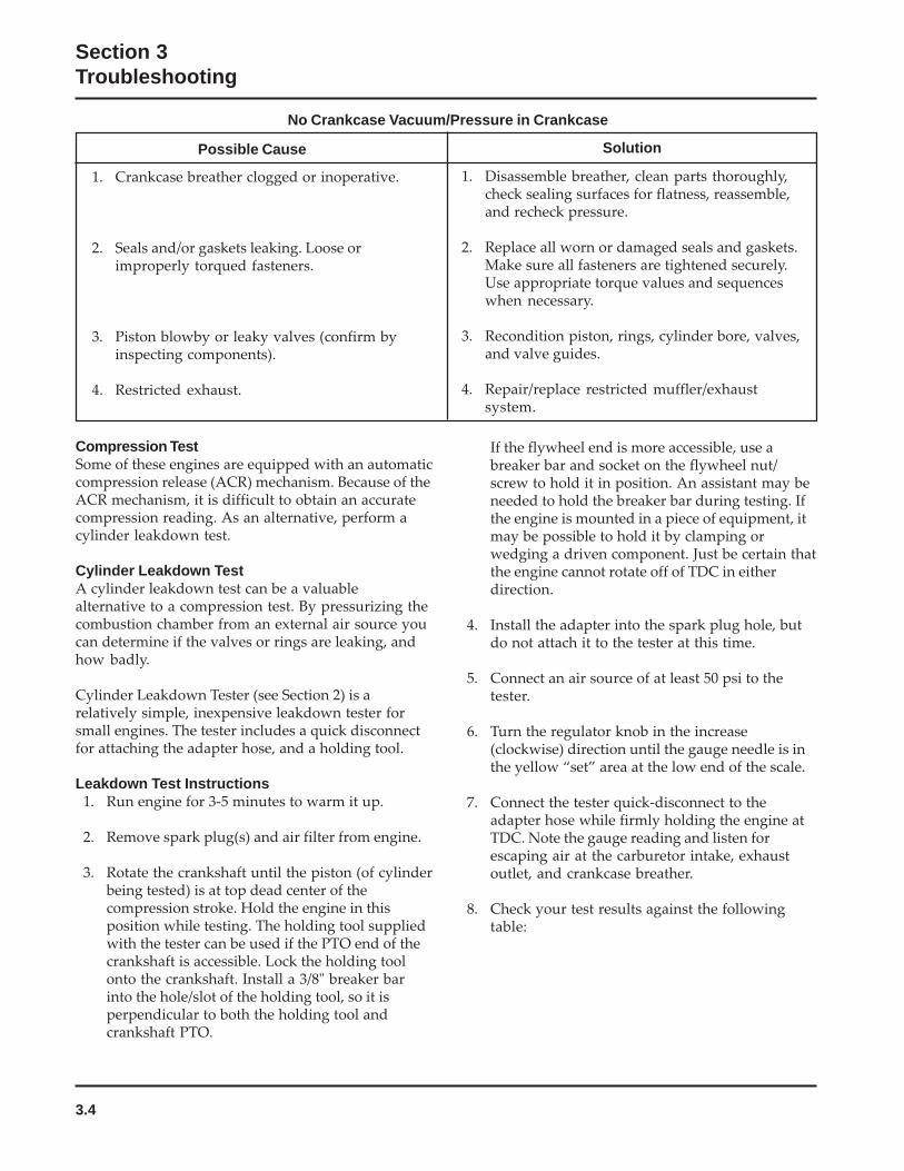
Figure 4-2. Removing Latch Style Cover.
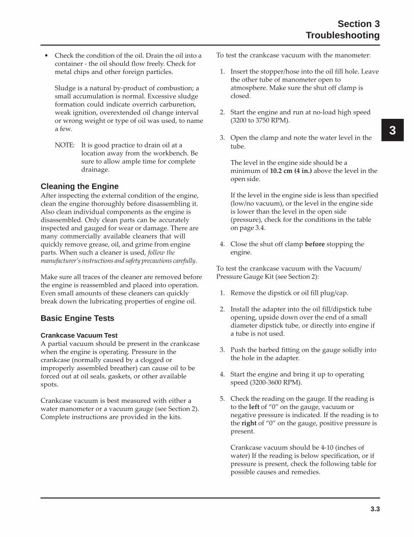
Figure 4-1. Standard Air Cleaner.
Standard Air Cleaner
ServiceCheck the air cleaner daily or before starting theengine. Check for and correct any buildup of dirt anddebris, along with loose or damaged components.
NOTE: Operating the engine with loose or damagedair cleaner components could allowunfiltered air into the engine, causingpremature wear and failure.
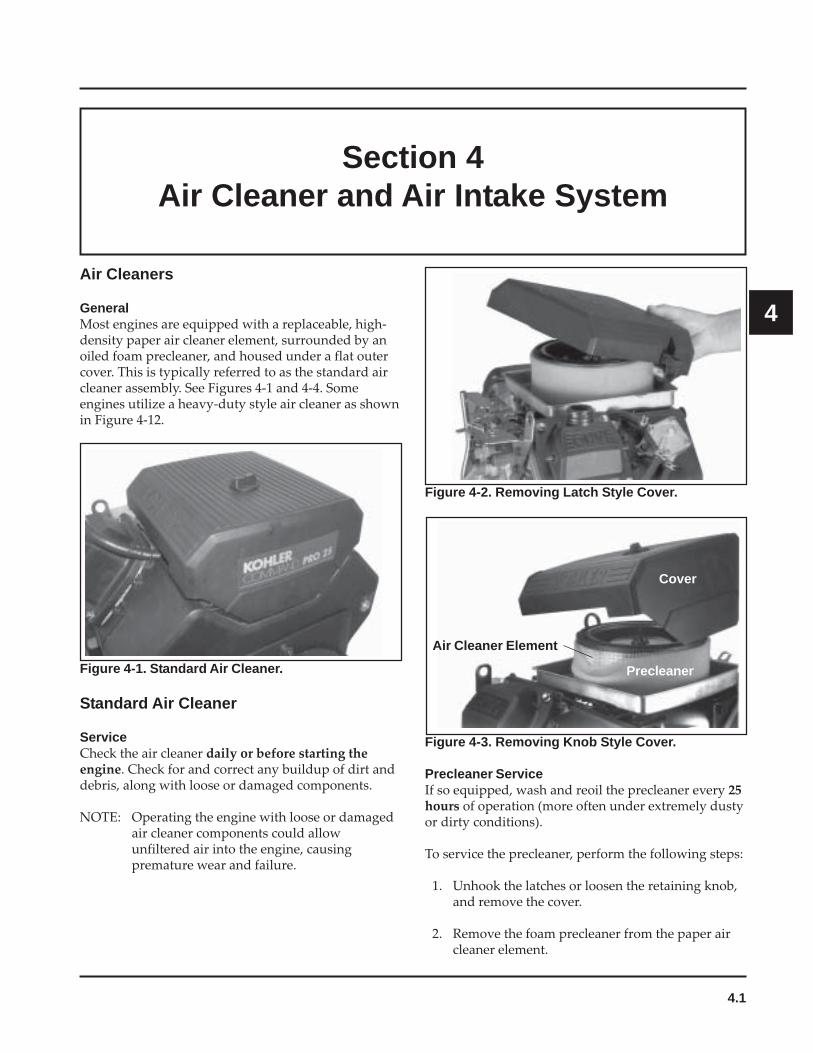
Figure 4-3. Removing Knob Style Cover.
Precleaner ServiceIf so equipped, wash and reoil the precleaner every 25hours of operation (more often under extremely dustyor dirty conditions).
To service the precleaner, perform the following steps:
1. Unhook the latches or loosen the retaining knob,and remove the cover.
2. Remove the foam precleaner from the paper aircleaner element.
Cover
Precleaner
Air Cleaner Element

4.2
Section 4Air Cleaner and Air Intake System
3. Wash the precleaner in warm water withdetergent. Rinse the precleaner thoroughly untilall traces of detergent are eliminated. Squeeze outexcess water (do not wring). Allow the precleanerto air dry.
4. Saturate the precleaner with new engine oil.Squeeze out all excess oil.
5. Reinstall the precleaner over the paper air cleanerelement.
6. Reinstall the air cleaner cover. Secure the coverwith the two latches or the retaining knob.
Figure 4-6. Removing Elements.
Figure 4-7. Removing Rubber Seal from Bracket.
Paper Element Service (Standard Type)Every 100 hours of operation (more often underextremely dusty or dirty conditions), replace the paperelement. Follow these steps:
1. Unhook the latches or loosen the retaining knob,and remove the cover.
2. Remove the wing nut, element cover, and paperelement with precleaner (if so equipped).
3. Remove the precleaner (if so equipped) from thepaper element. Service the precleaner asdescribed in "Precleaner Service".
4. Do not wash the paper element or usepressurized air, as this will damage the element.Replace a dirty, bent, or damaged element with agenuine Kohler element. Handle new elementscarefully; do not use if the sealing surfaces arebent or damaged.
Figure 4-4. Air Cleaner Components.
Element Cover Wing Nut
Precleaner
Element
Figure 4-5. Removing Element Cover Wing Nut.
Seal

4.3
Section 4Air Cleaner and Air Intake System
4
5. Check the seal for any damage or deterioration.Replace as necessary. See Figure 4-7.
6. Reinstall the seal, paper element, precleaner,element cover, and wing nut.
7. Reinstall the air cleaner cover and secure with thelatches or the retaining knob.
NOTE: Make sure the correct depth air cleanerelement and rubber seal are used for theengine spec involved. Some engines usea deeper or extra capacity air cleaner anda longer rubber seal.
Figure 4-8. Exploded View of Standard Air Intake System Components.
4.4
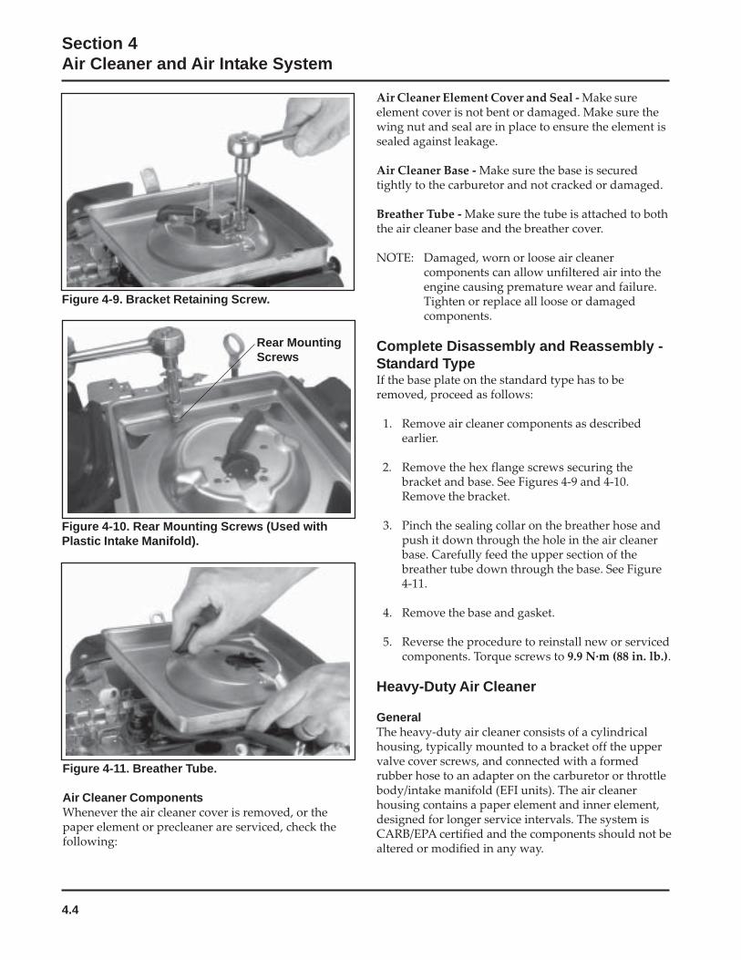
Section 4Air Cleaner and Air Intake System
Figure 4-9. Bracket Retaining Screw.
Air Cleaner Element Cover and Seal - Make sureelement cover is not bent or damaged. Make sure thewing nut and seal are in place to ensure the element issealed against leakage.
Air Cleaner Base - Make sure the base is securedtightly to the carburetor and not cracked or damaged.
Breather Tube - Make sure the tube is attached to boththe air cleaner base and the breather cover.
NOTE: Damaged, worn or loose air cleanercomponents can allow unfiltered air into theengine causing premature wear and failure.Tighten or replace all loose or damagedcomponents.
Complete Disassembly and Reassembly -Standard TypeIf the base plate on the standard type has to beremoved, proceed as follows:
1. Remove air cleaner components as describedearlier.
2. Remove the hex flange screws securing thebracket and base. See Figures 4-9 and 4-10.Remove the bracket.
3. Pinch the sealing collar on the breather hose andpush it down through the hole in the air cleanerbase. Carefully feed the upper section of thebreather tube down through the base. See Figure4-11.
4. Remove the base and gasket.
5. Reverse the procedure to reinstall new or servicedcomponents. Torque screws to 9.9 N·m (88 in. lb.).
Heavy-Duty Air Cleaner
GeneralThe heavy-duty air cleaner consists of a cylindricalhousing, typically mounted to a bracket off the uppervalve cover screws, and connected with a formedrubber hose to an adapter on the carburetor or throttlebody/intake manifold (EFI units). The air cleanerhousing contains a paper element and inner element,designed for longer service intervals. The system isCARB/EPA certified and the components should not bealtered or modified in any way.
Figure 4-10. Rear Mounting Screws (Used withPlastic Intake Manifold).
Figure 4-11. Breather Tube.
Air Cleaner ComponentsWhenever the air cleaner cover is removed, or thepaper element or precleaner are serviced, check thefollowing:
Rear MountingScrews
4.5
Section 4Air Cleaner and Air Intake System
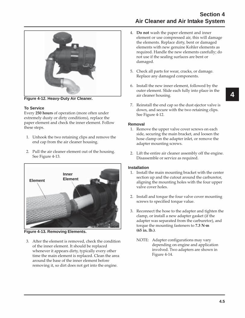
4Figure 4-12. Heavy-Duty Air Cleaner.
To ServiceEvery 250 hours of operation (more often underextremely dusty or dirty conditions), replace thepaper element and check the inner element. Followthese steps.
1. Unhook the two retaining clips and remove theend cap from the air cleaner housing.
2. Pull the air cleaner element out of the housing.See Figure 4-13.
4. Do not wash the paper element and innerelement or use compressed air, this will damagethe elements. Replace dirty, bent or damagedelements with new genuine Kohler elements asrequired. Handle the new elements carefully; donot use if the sealing surfaces are bent ordamaged.
5. Check all parts for wear, cracks, or damage.Replace any damaged components.
6. Install the new inner element, followed by theouter element. Slide each fully into place in theair cleaner housing.
7. Reinstall the end cap so the dust ejector valve isdown, and secure with the two retaining clips.See Figure 4-12.
Removal1. Remove the upper valve cover screws on each
side, securing the main bracket, and loosen thehose clamp on the adapter inlet, or remove theadapter mounting screws.
2. Lift the entire air cleaner assembly off the engine.Disassemble or service as required.
Installation1. Install the main mounting bracket with the center
section up and the cutout around the carburetor,aligning the mounting holes with the four uppervalve cover holes.
2. Install and torque the four valve cover mountingscrews to specified torque value.
3. Reconnect the hose to the adapter and tighten theclamp, or install a new adapter gasket (if theadapter was separated from the carburetor), andtorque the mounting fasteners to 7.3 N·m(65 in. lb.).
NOTE: Adapter configurations may varydepending on engine and applicationinvolved. Two adapters are shown inFigure 4-14.
Figure 4-13. Removing Elements.
3. After the element is removed, check the conditionof the inner element. It should be replacedwhenever it appears dirty, typically every othertime the main element is replaced. Clean the areaaround the base of the inner element beforeremoving it, so dirt does not get into the engine.
InnerElementElement
4.6
Section 4Air Cleaner and Air Intake System
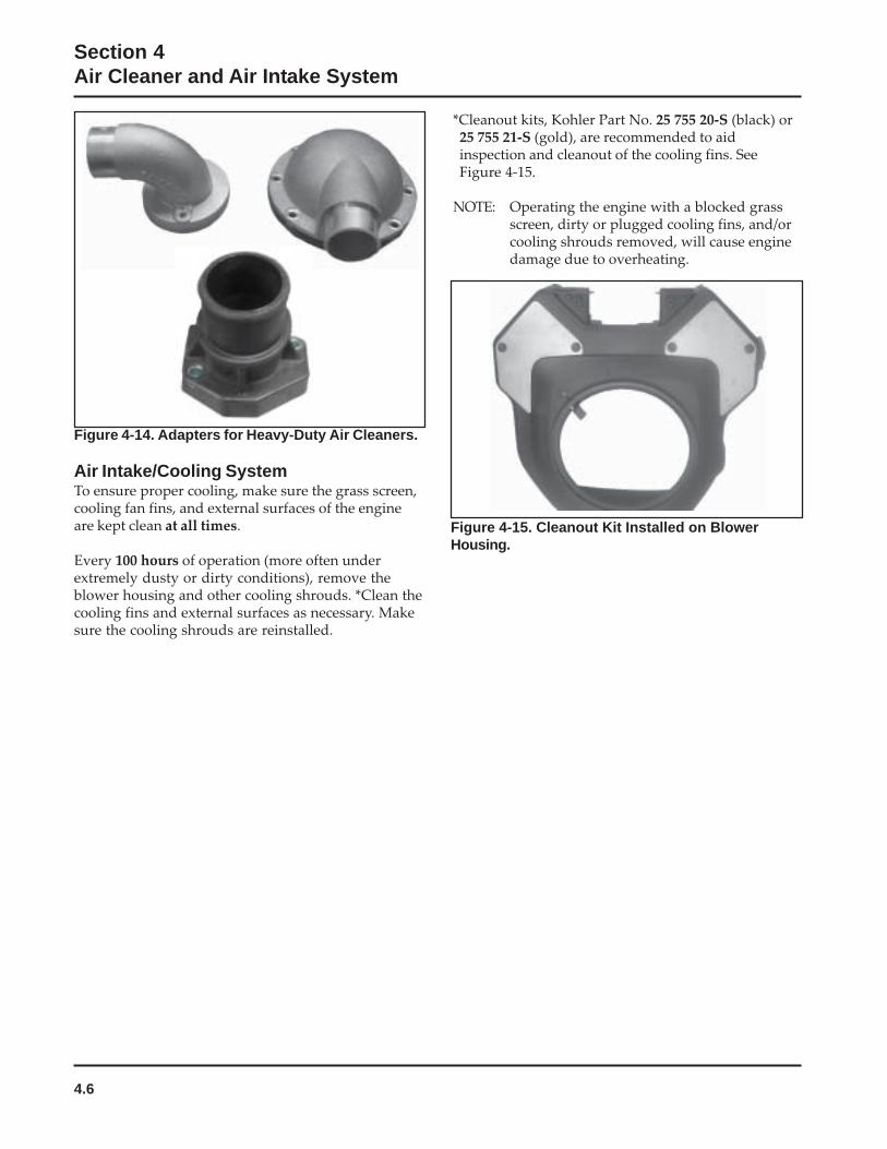
Figure 4-14. Adapters for Heavy-Duty Air Cleaners.
Air Intake/Cooling SystemTo ensure proper cooling, make sure the grass screen,cooling fan fins, and external surfaces of the engineare kept clean at all times.
Every 100 hours of operation (more often underextremely dusty or dirty conditions), remove theblower housing and other cooling shrouds. *Clean thecooling fins and external surfaces as necessary. Makesure the cooling shrouds are reinstalled.
Figure 4-15. Cleanout Kit Installed on BlowerHousing.
*Cleanout kits, Kohler Part No. 25 755 20-S (black) or25 755 21-S (gold), are recommended to aidinspection and cleanout of the cooling fins. SeeFigure 4-15.
NOTE: Operating the engine with a blocked grassscreen, dirty or plugged cooling fins, and/orcooling shrouds removed, will cause enginedamage due to overheating.
5.1
Section 5Fuel System and Governor
5
Section 5Fuel System and Governor
DescriptionThe Command horizontal twins use three differenttypes of fuel systems; carbureted, electronic fuelinjection (EFI), or gaseous. Gaseous fuel systems canbe either liquefied petroleum gas (LPG or LP) ornatural gas (NG). Some dual-fuel engines have acombination system, which allows the operator toselect either gasoline or LP.
This section covers the standard carbureted fuelsystems. The gaseous systems are covered insubsection 5A and the EFI systems are covered insubsection 5B. The governor systems used are coveredat the end of this section.
WARNING: Explosive Fuel!Gasoline is extremely flammable and its vapors can explodeif ignited. Store gasoline only in approved containers, inwell ventilated, unoccupied buildings, away from sparks orflames. Do not fill the fuel tank while the engine is hot orrunning, since spilled fuel could ignite if it comes in contactwith hot parts or sparks from ignition. Do not start theengine near spilled fuel. Never use gasoline as a cleaningagent.
Fuel System ComponentsThe typical carbureted fuel system and relatedcomponents include the following:
• Fuel Tank• Fuel Lines• In-line Fuel Filter• Fuel Pump• Carburetor
OperationThe fuel from the tank is moved through the in-linefilter and fuel lines by the fuel pump. On engines notequipped with a fuel pump, the fuel tank outlet islocated above the carburetor inlet allowing gravity tofeed fuel to the carburetor.
Fuel then enters the carburetor float bowl and isdrawn into the carburetor body. There, the fuel ismixed with air. This fuel-air mixture is then burned inthe engine combustion chamber.
Fuel Recommendations
General RecommendationsPurchase gasoline in small quantities and store inclean, approved containers. A container with acapacity of 2 gallons or less with a pouring spout isrecommended. Such a container is easier to handleand helps eliminate spillage during refueling.
• Do not use gasoline left over from the previousseason, to minimize gum deposits in your fuelsystem and to ensure easy starting.
• Do not add oil to the gasoline.
• Do not overfill the fuel tank. Leave room for thefuel to expand.
Fuel TypeFor best results, use only clean, fresh, unleadedgasoline with a pump sticker octane rating of 87 orhigher. In countries using the Research fuel ratingmethod, it should be 90 octane minimum.
Unleaded gasoline is recommended as it leaves lesscombustion chamber deposits and reduces harmfulexhaust emissions. Leaded gasoline is notrecommended and must not be used on EFI engines,or on other models where exhaust emissions areregulated.
Gasoline/Alcohol blendsGasohol (up to 10% ethyl alcohol, 90% unleadedgasoline by volume) is approved as a fuel for Kohlerengines. Other gasoline/alcohol blends are notapproved.
5.2
Section 5Fuel System and Governor
Gasoline/Ether blendsMethyl Tertiary Butyl Ether (MTBE) and unleadedgasoline blends (up to a maximum of 15% MTBE byvolume) are approved as a fuel for Kohler engines.Other gasoline/ether blends are not approved.
Fuel FilterMost engines are equipped with an in-line fuel filter.Periodically inspect the filter and replace with agenuine Kohler filter every 200 operating hours.
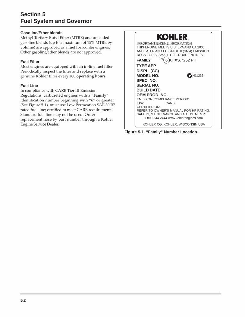
Fuel LineIn compliance with CARB Tier III EmissionRegulations, carbureted engines with a “Family”identification number beginning with “6” or greater(See Figure 5-1), must use Low Permeation SAE 30 R7rated fuel line; certified to meet CARB requirements.Standard fuel line may not be used. Orderreplacement hose by part number through a KohlerEngine Service Dealer.
Figure 5-1. “Family” Number Location.
KOHLER CO. KOHLER, WISCONSIN USA
EMISSION COMPLIANCE PERIOD:EPA: CARB:CERTIFIED ON:REFER TO OWNER'S MANUAL FOR HP RATING,SAFETY, MAINTENANCE AND ADJUSTMENTS
1-800-544-2444 www.kohlerengines.com
FAMILY 6 KHXS.7252 PHTYPE APPDISPL. (CC)MODEL NO.SPEC. NO.SERIAL NO.BUILD DATEOEM PROD. NO.
IMPORTANT ENGINE INFORMATIONTHIS ENGINE MEETS U.S. EPA AND CA 2005AND LATER AND EC STAGE II (SN:4) EMISSIONREGS FOR SI SMALL OFF–ROAD ENGINES
N11236
5.3
Section 5Fuel System and Governor
5
Troubleshooting – Fuel System Related Causes
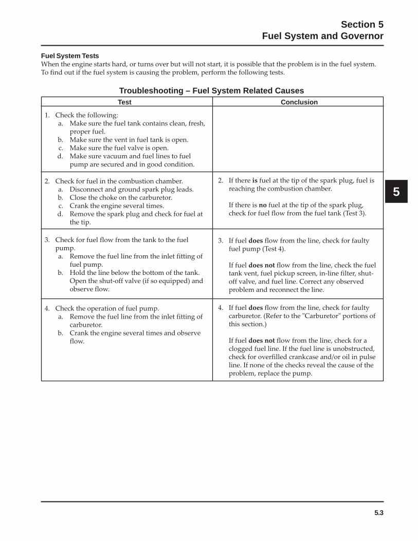
Fuel System TestsWhen the engine starts hard, or turns over but will not start, it is possible that the problem is in the fuel system.To find out if the fuel system is causing the problem, perform the following tests.
Test Conclusion
1. Check the following:a. Make sure the fuel tank contains clean, fresh,
proper fuel.b. Make sure the vent in fuel tank is open.c. Make sure the fuel valve is open.d. Make sure vacuum and fuel lines to fuel
pump are secured and in good condition.
2. Check for fuel in the combustion chamber.a. Disconnect and ground spark plug leads.b. Close the choke on the carburetor.c. Crank the engine several times.d. Remove the spark plug and check for fuel at
the tip.
2. If there is fuel at the tip of the spark plug, fuel isreaching the combustion chamber.
If there is no fuel at the tip of the spark plug,check for fuel flow from the fuel tank (Test 3).
3. Check for fuel flow from the tank to the fuelpump.a. Remove the fuel line from the inlet fitting of
fuel pump.b. Hold the line below the bottom of the tank.
Open the shut-off valve (if so equipped) andobserve flow.
3. If fuel does flow from the line, check for faultyfuel pump (Test 4).
If fuel does not flow from the line, check the fueltank vent, fuel pickup screen, in-line filter, shut-off valve, and fuel line. Correct any observedproblem and reconnect the line.
4. Check the operation of fuel pump.a. Remove the fuel line from the inlet fitting of
carburetor.b. Crank the engine several times and observe
flow.
4. If fuel does flow from the line, check for faultycarburetor. (Refer to the "Carburetor" portions ofthis section.)
If fuel does not flow from the line, check for aclogged fuel line. If the fuel line is unobstructed,check for overfilled crankcase and/or oil in pulseline. If none of the checks reveal the cause of theproblem, replace the pump.

5.4
Section 5Fuel System and Governor
NOTE: On most models, the pulse line isconnected to a fitting on the crankcase,while on early models, it is connected tothe valve cover.
4. Install the new fuel pump using the hex flangescrews. Torque the hex flange screws to 2.3 N·m(20 in. lb.).
NOTE: Make sure the orientation of the newpump is consistent with the removedpump. Internal damage may occur ifinstalled incorrectly.
5. Connect the pulse line to the pulse fitting.
6. Connect the fuel lines to the inlet and outletfittings.
Replacing the Mechanical PumpThe mechanical pump is an integral part of the valvecover assembly and not serviced separately. See Figure5-3.
1. Disconnect the fuel lines from the inlet and outletfittings.
2. Follow the procedure for replacing the valvecover (Sections 9 and 11).
3. Reconnect the fuel lines to the inlet and outletfittings.
Figure 5-2. Pulse Style Fuel Pump.
PerformanceMinimum fuel delivery rate must be 7.5 L/hr.(2 gal./hr.) with a pressure at 0.3 psi and a fuel lift of18 in. from carburetor inlet. A 1.3 L/hr. (0.34 gal./hr.)fuel rate must be maintained at 5 Hz.
Fuel Pump - Replacement
Replacing the Pulse Fuel PumpReplacement pumps are available through yoursource of supply. To replace the pulse pump followthese steps:
1. Disconnect the fuel lines from the inlet and outletfittings.
2. Remove the hex flange screws securing the fuelpump.
3. Remove the pulse line that connects the pump tothe crankcase or valve cover.
Fuel Pump
GeneralThese engines are equipped with either a pulse ormechanical fuel pump. See Figures 5-2 and 5-3. Thepumping action is created by either the oscillation ofpositive and negative pressures within the crankcasethrough a hose, or by direct lever/pump actuation offrocker arm movement. The pumping action causes thediaphragm on the inside of the pump to pull fuel inon its downward stroke and to push it into thecarburetor on its upward stroke. Internal check valvesprevent fuel from going backward through the pump.
Figure 5-3. Mechanical Fuel Pump.
Pulse Line
Outlet Line (to Carburetor)
Pulse FuelPump
Inlet Line
Outlet Line (toCarburetor)
MechanicalFuel Pump
Inlet Line
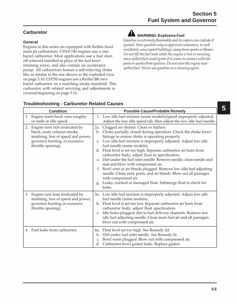
5.5
Section 5Fuel System and Governor
5
Carburetor
GeneralEngines in this series are equipped with Keihin fixedmain jet carburetors. CH18-740 engines use a one-barrel carburetor. Most applications use a fuel shut-off solenoid installed in place of the fuel bowlretaining screw, and also contain an acceleratorpump. All carburetors feature a self-relieving chokelike or similar to the one shown in the exploded viewon page 5.10. CH750 engines use a Keihin BK two-barrel carburetor on a matching intake manifold. Thiscarburetor with related servicing and adjustments iscovered beginning on page 5.11.
WARNING: Explosive FuelGasoline is extremely flammable and its vapors can explode ifignited. Store gasoline only in approved containers, in wellventilated, unoccupied buildings, away from sparks or flames.Do not fill the fuel tank while the engine is hot or running,since spilled fuel could ignite if it comes in contact with hotparts or sparks from ignition. Do not start the engine nearspilled fuel. Never use gasoline as a cleaning agent.
Troubleshooting - Carburetor Related Causes
Condition Possible Cause/Probable Remedy1. Low idle fuel mixture (some models)/speed improperly adjusted.
Adjust the low idle speed tab, then adjust the low idle fuel needle.1. Engine starts hard, runs roughly
or stalls at idle speed.
2. Engine runs rich (indicated byblack, sooty exhaust smoke,misfiring, loss of speed and power,governor hunting, or excessivethrottle opening).
2a. Clogged air cleaner. Clean or replace.b. Choke partially closed during operation. Check the choke lever/
linkage to ensure choke is operating properly.c. Low idle fuel mixture is improperly adjusted. Adjust low idle
fuel needle (some models).d. Float level is set too high. Separate carburetor air horn from
carburetor body, adjust float to specification.e. Dirt under the fuel inlet needle. Remove needle; clean needle and
seat and blow with compressed air.f. Bowl vent or air bleeds plugged. Remove low idle fuel adjusting
needle. Clean vent, ports, and air bleeds. Blow out all passageswith compressed air.
g. Leaky, cracked or damaged float. Submerge float to check forleaks.
3. Engine runs lean (indicated bymisfiring, loss of speed and power,governor hunting or excessivethrottle opening).
3a. Low idle fuel mixture is improperly adjusted. Adjust low idlefuel needle (some models).
b. Float level is set too low. Separate carburetor air horn fromcarburetor body, adjust float specification.
c. Idle holes plugged; dirt in fuel delivery channels. Remove lowidle fuel adjusting needle. Clean main fuel jet and all passages;blow out with compressed air.
4. Fuel leaks from carburetor. 4a. Float level set too high. See Remedy 2d.b. Dirt under fuel inlet needle. See Remedy 2e.c. Bowl vents plugged. Blow out with compressed air.d. Carburetor bowl gasket leaks. Replace gasket.

5.6
Section 5Fuel System and Governor
Troubleshooting ChecklistWhen the engine starts hard, runs roughly or stalls atlow idle speed, check the following areas beforeadjusting or disassembling the carburetor.
• Make sure the fuel tank is filled with clean, freshgasoline.
• Make sure the fuel tank cap vent is not blockedand that it is operating properly.
• Make sure fuel is reaching the carburetor. Thisincludes checking the fuel shut-off valve, fueltank filter screen, in-line fuel filter, fuel lines andfuel pump for restrictions or faulty componentsas necessary.
• Make sure the air cleaner base and carburetor aresecurely fastened to the engine using gaskets ingood condition.
• Make sure the air cleaner element (includingprecleaner if equipped) is clean and all air cleanercomponents are fastened securely.
• Make sure the ignition system, governor system,exhaust system, and throttle and choke controlsare operating properly.
If the engine is hard-starting, runs roughly, or stalls atlow idle speed, it may be necessary to adjust or servicethe carburetor.
High Altitude OperationWhen operating the engine at altitudes of 1500 m(5000 ft.) and above, the fuel mixture tends to get over-rich. This can cause conditions such as black, sootyexhaust smoke, misfiring, loss of speed and power,poor fuel economy, and poor or slow governorresponse.
To compensate for the effects of high altitude, specialhigh altitude jet kits are available. The kits include anew main jet, slow jet (where applicable), necessarygaskets and O-Rings. Refer to the parts manual for thecorrect kit number.
Fuel Shut-off SolenoidMost carburetors are equipped with a fuel shut-offsolenoid. The solenoid is attached in place of the fixedmain jet screw on the flywheel side of the carburetor.See Figure 5-4. The solenoid has a spring-loaded pinthat retracts when 12 volts is applied to the lead,allowing fuel flow through the main jet.
When current is removed the pin extends blockingthe main fuel jet and preventing fuel from enteringthe carburetor.
Figure 5-4. Fuel Shut-off Solenoid.
Below is a simple test, made with the engine off, thatcan determine if the solenoid is functioning properly:
1. Shut off fuel and remove the solenoid from thecarburetor. When the solenoid is loosened andremoved, gas will leak out of the carburetor.Have a container ready to catch the fuel.
2. Wipe the tip of the solenoid with a shop towel orblow it off with compressed air, to remove anyremaining fuel. Take the solenoid to a locationwith good ventilation and no fuel vapors present.You will also need a 12 volt power source that canbe switched on and off.
3. Be sure the power source is switched “off”.Connect the positive power source lead to the redlead of the solenoid. Connect the negative powersource lead to the solenoid bracket.
4. Turn the power source “on” and observe the pinin the center of the solenoid. The pin shouldretract with the power “on” and return to itsoriginal position with the power off. Test severaltimes to verify operation.
Fuel Shut-off Solenoid
Two-Barrel Carburetor
Fuel Shut-off Solenoid
One-Barrel Carburetor
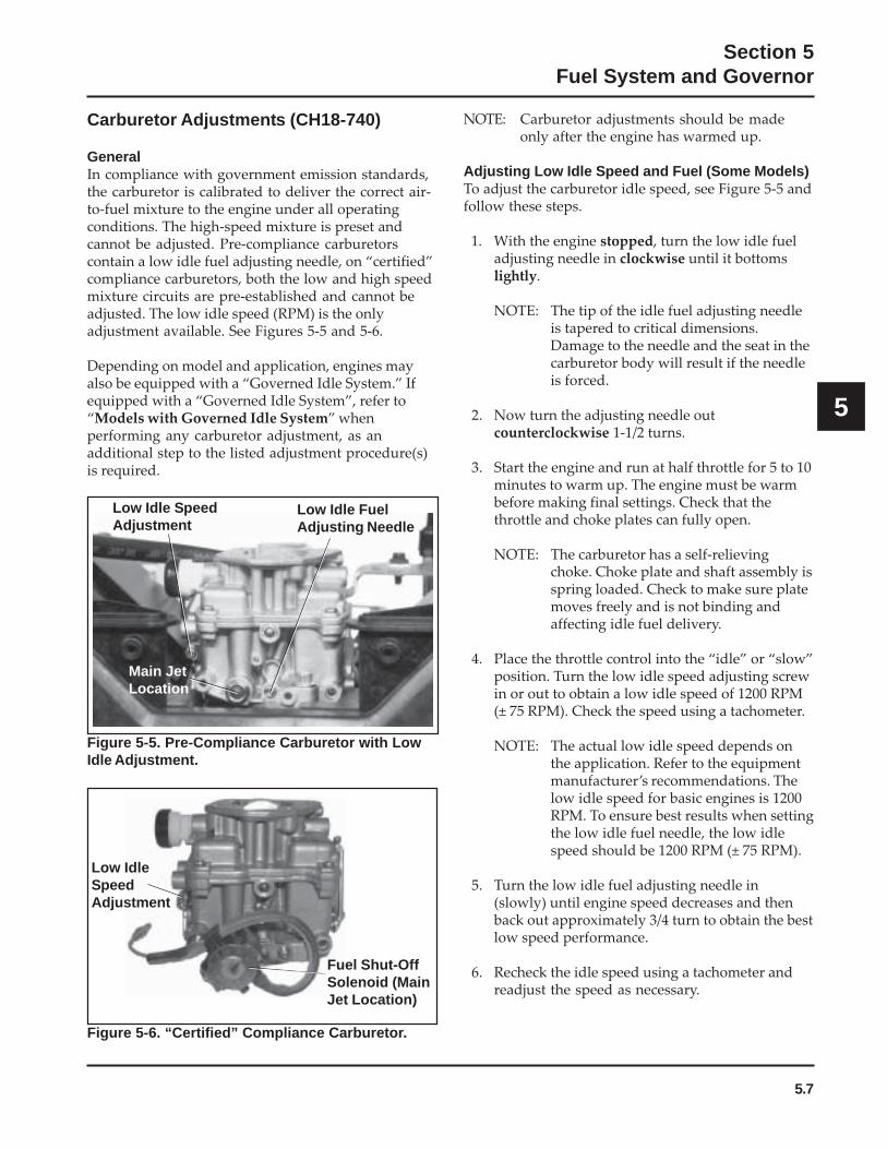
5.7
Section 5Fuel System and Governor
5
Figure 5-5. Pre-Compliance Carburetor with LowIdle Adjustment.
NOTE: Carburetor adjustments should be madeonly after the engine has warmed up.
Adjusting Low Idle Speed and Fuel (Some Models)To adjust the carburetor idle speed, see Figure 5-5 andfollow these steps.
1. With the engine stopped, turn the low idle fueladjusting needle in clockwise until it bottomslightly.
NOTE: The tip of the idle fuel adjusting needleis tapered to critical dimensions.Damage to the needle and the seat in thecarburetor body will result if the needleis forced.
2. Now turn the adjusting needle outcounterclockwise 1-1/2 turns.
3. Start the engine and run at half throttle for 5 to 10minutes to warm up. The engine must be warmbefore making final settings. Check that thethrottle and choke plates can fully open.
NOTE: The carburetor has a self-relievingchoke. Choke plate and shaft assembly isspring loaded. Check to make sure platemoves freely and is not binding andaffecting idle fuel delivery.
4. Place the throttle control into the “idle” or “slow”position. Turn the low idle speed adjusting screwin or out to obtain a low idle speed of 1200 RPM(± 75 RPM). Check the speed using a tachometer.
NOTE: The actual low idle speed depends onthe application. Refer to the equipmentmanufacturer’s recommendations. Thelow idle speed for basic engines is 1200RPM. To ensure best results when settingthe low idle fuel needle, the low idlespeed should be 1200 RPM (± 75 RPM).
5. Turn the low idle fuel adjusting needle in(slowly) until engine speed decreases and thenback out approximately 3/4 turn to obtain the bestlow speed performance.
6. Recheck the idle speed using a tachometer andreadjust the speed as necessary.
Carburetor Adjustments (CH18-740)
GeneralIn compliance with government emission standards,the carburetor is calibrated to deliver the correct air-to-fuel mixture to the engine under all operatingconditions. The high-speed mixture is preset andcannot be adjusted. Pre-compliance carburetorscontain a low idle fuel adjusting needle, on “certified”compliance carburetors, both the low and high speedmixture circuits are pre-established and cannot beadjusted. The low idle speed (RPM) is the onlyadjustment available. See Figures 5-5 and 5-6.
Depending on model and application, engines mayalso be equipped with a “Governed Idle System.” Ifequipped with a “Governed Idle System”, refer to“Models with Governed Idle System” whenperforming any carburetor adjustment, as anadditional step to the listed adjustment procedure(s)is required.
Low Idle SpeedAdjustment
Low Idle FuelAdjusting Needle
Main JetLocation
Figure 5-6. “Certified” Compliance Carburetor.
Low IdleSpeedAdjustment
Fuel Shut-OffSolenoid (MainJet Location)
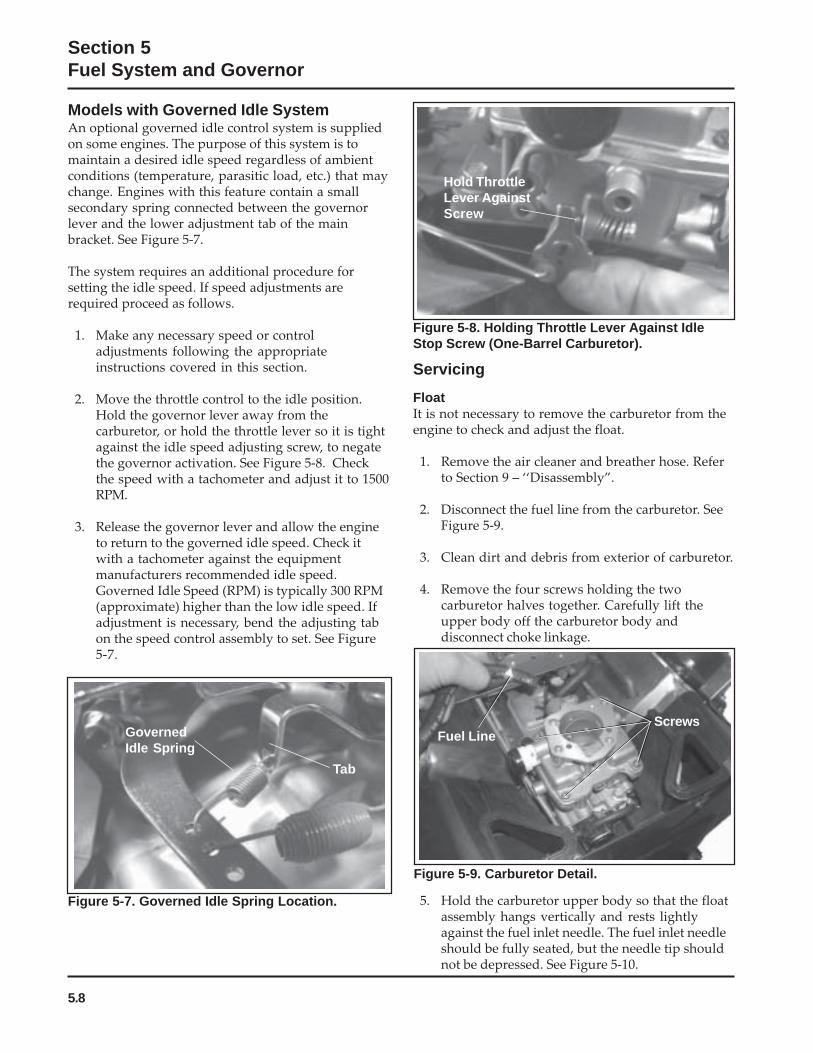
5.8
Section 5Fuel System and Governor
Models with Governed Idle SystemAn optional governed idle control system is suppliedon some engines. The purpose of this system is tomaintain a desired idle speed regardless of ambientconditions (temperature, parasitic load, etc.) that maychange. Engines with this feature contain a smallsecondary spring connected between the governorlever and the lower adjustment tab of the mainbracket. See Figure 5-7.
The system requires an additional procedure forsetting the idle speed. If speed adjustments arerequired proceed as follows.
1. Make any necessary speed or controladjustments following the appropriateinstructions covered in this section.
2. Move the throttle control to the idle position.Hold the governor lever away from thecarburetor, or hold the throttle lever so it is tightagainst the idle speed adjusting screw, to negatethe governor activation. See Figure 5-8. Checkthe speed with a tachometer and adjust it to 1500RPM.
3. Release the governor lever and allow the engineto return to the governed idle speed. Check itwith a tachometer against the equipmentmanufacturers recommended idle speed.Governed Idle Speed (RPM) is typically 300 RPM(approximate) higher than the low idle speed. Ifadjustment is necessary, bend the adjusting tabon the speed control assembly to set. See Figure5-7.
Figure 5-7. Governed Idle Spring Location.
GovernedIdle Spring
Tab
Hold ThrottleLever AgainstScrew
Servicing
Figure 5-9. Carburetor Detail.
ScrewsFuel Line
Figure 5-8. Holding Throttle Lever Against IdleStop Screw (One-Barrel Carburetor).
FloatIt is not necessary to remove the carburetor from theengine to check and adjust the float.
1. Remove the air cleaner and breather hose. Referto Section 9 – ‘‘Disassembly”.
2. Disconnect the fuel line from the carburetor. SeeFigure 5-9.
3. Clean dirt and debris from exterior of carburetor.
4. Remove the four screws holding the twocarburetor halves together. Carefully lift theupper body off the carburetor body anddisconnect choke linkage.
5. Hold the carburetor upper body so that the floatassembly hangs vertically and rests lightlyagainst the fuel inlet needle. The fuel inlet needleshould be fully seated, but the needle tip shouldnot be depressed. See Figure 5-10.

5.9
Section 5Fuel System and Governor
5
NOTE: The fuel inlet needle tip is spring loaded.Make sure the float assembly restsagainst the fuel inlet needle withoutdepressing the tip.
6. The correct float height adjustment is 22 mm(0.86 in.), measured from the float bottom to theair horn casting. Adjust the float height bycarefully bending the tab.
NOTE: Be sure to measure from the castingsurface, not the rubber gasket surface.
7. If proper float height adjustment cannot beachieved, check to see if the fuel inlet needle isdirty, obstructed or worn. Remove the brassscrew and float assembly to remove the fuel inletneedle.
2. Remove the four screws and carefully separatethe air horn assembly from the carburetor body.
3. Loosen the screw securing the float assembly tothe air horn and remove the float, float shaft andfuel inlet needle.
4. Remove the slow jet from the carburetor body.
NOTE: The main jet is a fixed jet and can beremoved if required. Fixed jets for highaltitude are available.
5. Remove the black cap on the end of the chokeshaft only if it is necessary to inspect and cleanthe shaft spring.
6. Remove the low idle speed adjusting screw andspring from the carburetor body.
7. In order to clean the ‘‘off-idle’’ vent ports andbowl vent thoroughly, use a good carburetorsolvent (like Gumout™). Blow clean compressedair through the idle adjusting needle hole. Becareful to use a suitable shop rag to preventdebris from hitting someone.
8. Remove the preformed rubber gasket only if it isto be replaced. If it is removed for any reason,replace it.
Inspection/RepairCarefully inspect all components and replace thosethat are worn or damaged.
• Inspect the carburetor body for cracks, holes andother wear or damage.
• Inspect the float for cracks, holes, and missing ordamaged float tabs. Check the float hinge andshaft for wear or damage.
• Inspect the fuel inlet needle and seat for wear ordamage.
• Inspect the tip of the low idle fuel adjustingneedle for wear or grooves.
• The choke plate is spring loaded. Check to makesure it moves freely on the shaft.
Figure 5-10. Carburetor Float Adjustment.
8. Once the proper float height is obtained,carefully lower the carburetor air horn assemblyonto the carburetor body, connecting the chokelinkage. Install the four screws. Torque thescrews to 1.7 N·m (15 in. lb.). See Figure 5-9.
9. Connect the fuel line.
10. Install the breather hose and air cleanerassembly, following the steps in Section 11 –‘‘Reassembly”.
DisassemblyDisassemble the carburetor using the following steps.See Figure 5-11.
1. Remove the air cleaner, breather hose andcarburetor. Refer to Section 9 – “Disassembly”.
Tab
Float

5.10
Section 5Fuel System and Governor
NOTE: The choke and throttle plate assembliesare staked and matched to the shafts atthe factory. They are not serviceableitems.
Always use new gaskets when servicing orreinstalling carburetors. Repair kits are availablewhich include new gaskets and other components.These kits are described on the next page.
ReassemblyReassemble the carburetor using the following steps.See Figure 5-11.
1. Assemble the fuel inlet needle to the float tab.Install the float, float shaft and inlet needle to the
air horn. Tighten the screw. Check float heightusing the procedure found previously in the‘‘Adjustments’’ subsection.
2. Install the slow jet with the stepped end towardthe bottom of the carburetor. Make sure jet isfully seated.
3. Install the low idle adjusting needle and spring.
4. Assemble the upper body onto the lowercarburetor body using the four screws. Torquethe screws to 1.7 N·m (15 in. lb.).
5. Install the carburetor on the engine following theprocedures in Section 11 – ‘‘Reassembly.’’
1. Carburetor Upper Body (Choke)2. Self-relieving Choke3. Body Gasket (Formed Rubber)4. Slow Speed Jet5. Inlet Needle Valve6. Clip7. Float Pin8. Float Assembly (Kit)9. Carburetor Lower Body (Throttle)
10. Main Jet11. Idle Fuel Adjusting Needle (some models)12. Solenoid Seat13. Fuel Shut-off Solenoid (Kit)14. Idle Speed Adjusting Screw15. Jet (Accelerator Pump Carburetor only)16. Accelerator Pump Cover17. Diaphragm18. Diaphragm Spring19. O-Ring20. Rubber Boot21. Bushing22. Return Spring
Accelerator Pump Version Only
12
3
415
8
5
6
7
9
10
1214
13
19
17
18
16
21
20 22
19
#See Note on Page 5.1111
Figure 5-11. CH18-740 Carburetor – Exploded View.
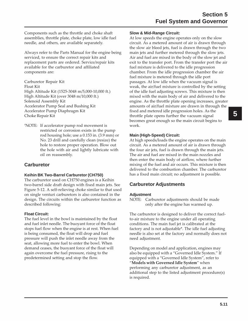
5.11
Section 5Fuel System and Governor
5
Components such as the throttle and choke shaftassemblies, throttle plate, choke plate, low idle fuelneedle, and others, are available separately.
Always refer to the Parts Manual for the engine beingserviced, to ensure the correct repair kits andreplacement parts are ordered. Service/repair kitsavailable for the carburetor and affiliatedcomponents are:
Carburetor Repair KitFloat KitHigh Altitude Kit (1525-3048 m/5,000-10,000 ft.)High Altitude Kit (over 3048 m/10,000 ft.)Solenoid Assembly KitAccelerator Pump Seal and Bushing KitAccelerator Pump Diaphragm KitChoke Repair Kit
#NOTE: If accelerator pump rod movement isrestricted or corrosion exists in the pumprod housing hole; use a 0.153 in. (3.9 mm) orNo. 23 drill and carefully clean (resize) thehole to restore proper operation. Blow outthe hole with air and lightly lubricate withoil on reassembly.
Carburetor
Keihin BK Two-Barrel Carburetor (CH750)The carburetor used on CH750 engines is a Keihintwo-barrel side draft design with fixed main jets. SeeFigure 5-12. A self-relieving choke similar to that usedon single venturi carburetors is also contained in thedesign. The circuits within the carburetor function asdescribed following:
Float Circuit:The fuel level in the bowl is maintained by the floatand fuel inlet needle. The buoyant force of the floatstops fuel flow when the engine is at rest. When fuelis being consumed, the float will drop and fuelpressure will push the inlet needle away from theseat, allowing more fuel to enter the bowl. Whendemand ceases, the buoyant force of the float willagain overcome the fuel pressure, rising to thepredetermined setting and stop the flow.
Slow & Mid-Range Circuit:At low speeds the engine operates only on the slowcircuit. As a metered amount of air is drawn throughthe slow air bleed jets, fuel is drawn through the twomain jets and further metered through the slow jets.Air and fuel are mixed in the body of the slow jet andexit to the transfer port. From the transfer port the airfuel mixture is delivered to the idle progressionchamber. From the idle progression chamber the airfuel mixture is metered through the idle portpassages. At low idle when the vacuum signal isweak, the air/fuel mixture is controlled by the settingof the idle fuel adjusting screws. This mixture is thenmixed with the main body of air and delivered to theengine. As the throttle plate opening increases, greateramounts of air/fuel mixture are drawn in through thefixed and metered idle progression holes. As thethrottle plate opens further the vacuum signalbecomes great enough so the main circuit begins towork.
Main (High-Speed) Circuit:At high speeds/loads the engine operates on the maincircuit. As a metered amount of air is drawn throughthe four air jets, fuel is drawn through the main jets.The air and fuel are mixed in the main nozzles andthen enter the main body of airflow, where furthermixing of the fuel and air occurs. This mixture is thendelivered to the combustion chamber. The carburetorhas a fixed main circuit; no adjustment is possible.
Carburetor Adjustments
AdjustmentNOTE: Carburetor adjustments should be made
only after the engine has warmed up.
The carburetor is designed to deliver the correct fuel-to-air mixture to the engine under all operatingconditions. The main fuel jet is calibrated at thefactory and is not adjustable*. The idle fuel adjustingneedle is also set at the factory and normally does notneed adjustment.
Depending on model and application, engines mayalso be equipped with a “Governed Idle System.” Ifequipped with a “Governed Idle System”, refer to“Models with Governed Idle System” whenperforming any carburetor adjustment, as anadditional step to the listed adjustment procedure(s)is required.
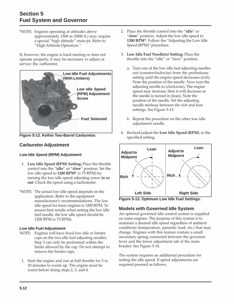
5.12
Section 5Fuel System and Governor
Lean
Rich
Adjust toMidpoint
Lean
Rich
Adjust toMidpoint
Left Side Right Side
*NOTE: Engines operating at altitudes aboveapproximately 1500 m (5000 ft.) may requirea special ‘‘high altitude’’ main jet. Refer to‘‘High Altitude Operation.’’
If, however, the engine is hard-starting or does notoperate properly, it may be necessary to adjust orservice the carburetor.
2. Place the throttle control into the “idle” or“slow” position. Adjust the low idle speed to1200 RPM*. Follow the “Adjusting the Low IdleSpeed (RPM)” procedure.
3. Low Idle Fuel Needle(s) Setting: Place thethrottle into the “idle” or “slow” position.
a. Turn one of the low idle fuel adjusting needlesout (counterclockwise) from the preliminarysetting until the engine speed decreases (rich).Note the position of the needle. Now turn theadjusting needle in (clockwise). The enginespeed may increase, then it will decrease asthe needle is turned in (lean). Note theposition of the needle. Set the adjustingneedle midway between the rich and leansettings. See Figure 5-13.
b. Repeat the procedure on the other low idleadjustment needle.
4. Recheck/adjust the Low Idle Speed (RPM), to thespecified setting.
Figure 5-13. Optimum Low Idle Fuel Settings.
Models with Governed Idle SystemAn optional governed idle control system is suppliedon some engines. The purpose of this system is tomaintain a desired idle speed regardless of ambientconditions (temperature, parasitic load, etc.) that maychange. Engines with this feature contain a smallsecondary spring connected between the governorlever and the lower adjustment tab of the mainbracket. See Figure 5-14.
The system requires an additional procedure forsetting the idle speed. If speed adjustments arerequired proceed as follows.
Low Idle Fuel Adjustments(With Limiters)
Low Idle Speed(RPM) AdjustmentScrew
Fuel Solenoid
Figure 5-12. Keihin Two-Barrel Carburetor.
Carburetor Adjustment
Low Idle Speed (RPM) Adjustment
1. Low Idle Speed (RPM) Setting: Place the throttlecontrol into the “idle” or “slow” position. Set thelow idle speed to 1200 RPM* (± 75 RPM) byturning the low idle speed adjusting screw in orout. Check the speed using a tachometer.
*NOTE: The actual low idle speed depends on theapplication. Refer to the equipmentmanufacturer’s recommendations. The lowidle speed for basic engines is 1200 RPM. Toensure best results when setting the low idlefuel needle, the low idle speed should be1200 RPM (± 75 RPM).
Low Idle Fuel AdjustmentNOTE: Engines will have fixed low idle or limiter
caps on the two idle fuel adjusting needles.Step 3 can only be performed within thelimits allowed by the cap. Do not attempt toremove the limiter caps.
1. Start the engine and run at half throttle for 5 to10 minutes to warm up. The engine must bewarm before doing steps 2, 3, and 4.
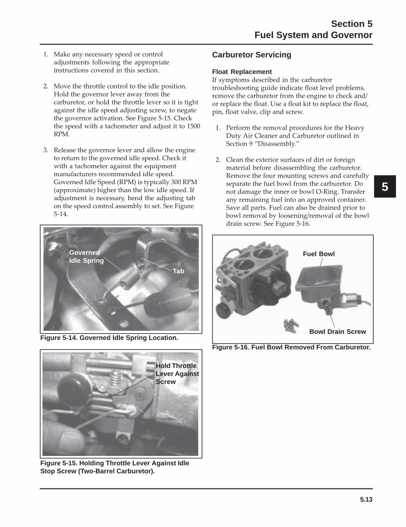
5.13
Section 5Fuel System and Governor
5
Carburetor Servicing
Float ReplacementIf symptoms described in the carburetortroubleshooting guide indicate float level problems,remove the carburetor from the engine to check and/or replace the float. Use a float kit to replace the float,pin, float valve, clip and screw.
1. Perform the removal procedures for the HeavyDuty Air Cleaner and Carburetor outlined inSection 9 “Disassembly.”
2. Clean the exterior surfaces of dirt or foreignmaterial before disassembling the carburetor.Remove the four mounting screws and carefullyseparate the fuel bowl from the carburetor. Donot damage the inner or bowl O-Ring. Transferany remaining fuel into an approved container.Save all parts. Fuel can also be drained prior tobowl removal by loosening/removal of the bowldrain screw. See Figure 5-16.
1. Make any necessary speed or controladjustments following the appropriateinstructions covered in this section.
2. Move the throttle control to the idle position.Hold the governor lever away from thecarburetor, or hold the throttle lever so it is tightagainst the idle speed adjusting screw, to negatethe governor activation. See Figure 5-15. Checkthe speed with a tachometer and adjust it to 1500RPM.
3. Release the governor lever and allow the engineto return to the governed idle speed. Check itwith a tachometer against the equipmentmanufacturers recommended idle speed.Governed Idle Speed (RPM) is typically 300 RPM(approximate) higher than the low idle speed. Ifadjustment is necessary, bend the adjusting tabon the speed control assembly to set. See Figure5-14.
Figure 5-16. Fuel Bowl Removed From Carburetor.
Fuel Bowl
Bowl Drain ScrewFigure 5-14. Governed Idle Spring Location.
GovernedIdle Spring
Tab
Figure 5-15. Holding Throttle Lever Against IdleStop Screw (Two-Barrel Carburetor).
Hold ThrottleLever AgainstScrew
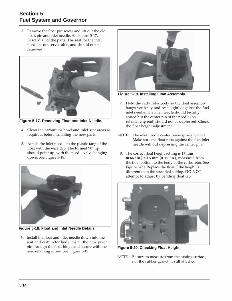
5.14
Section 5Fuel System and Governor
Figure 5-20. Checking Float Height.
NOTE: Be sure to measure from the casting surface,not the rubber gasket, if still attached.
Figure 5-17. Removing Float and Inlet Needle.
4. Clean the carburetor bowl and inlet seat areas asrequired, before installing the new parts.
5. Attach the inlet needle to the plastic tang of thefloat with the wire clip. The formed 90° lipshould point up, with the needle valve hangingdown. See Figure 5-18.
Figure 5-18. Float and Inlet Needle Details.
6. Install the float and inlet needle down into theseat and carburetor body. Install the new pivotpin through the float hinge and secure with thenew retaining screw. See Figure 5-19.
3. Remove the float pin screw and lift out the oldfloat, pin and inlet needle. See Figure 5-17.Discard all of the parts. The seat for the inletneedle is not serviceable, and should not beremoved.
Figure 5-19. Installing Float Assembly.
7. Hold the carburetor body so the float assemblyhangs vertically and rests lightly against the fuelinlet needle. The inlet needle should be fullyseated but the center pin of the needle (onretainer clip end) should not be depressed. Checkthe float height adjustment.
NOTE: The inlet needle center pin is spring loaded.Make sure the float rests against the fuel inletneedle without depressing the center pin.
8. The correct float height setting is 17 mm(0.669 in.) ± 1.5 mm (0.059 in.), measured fromthe float bottom to the body of the carburetor. SeeFigure 5-20. Replace the float if the height isdifferent than the specified setting. DO NOTattempt to adjust by bending float tab.

5.15
Section 5Fuel System and Governor
5
Figure 5-22. Fuel Bowl Removed From Carburetor.
Figure 5-21. Installing Fuel Bowl.
10. Install the carburetor and the heavy-duty aircleaner as outlined in Section 11 “Reassembly.”
Disassembly/Overhaul1. Clean the exterior surfaces of dirt or foreign
material before disassembling the carburetor.Remove the four mounting screws and separatethe fuel bowl from the carburetor. Transfer anyremaining fuel into an approved container.Remove and discard the old O-Rings. Fuel canalso be drained prior to bowl removal byloosening/removal of the bowl drain screw. SeeFigure 5-22.
Fuel Bowl
Bowl Drain Screw
Figure 5-23. Removing Float and Inlet Needle.
3. Use an appropriate size flat screwdriver, andcarefully remove the two main jets from thecarburetor. Note and mark the jets by locationfor proper reassembly. The main jets may besize/side specific. After the main jets areremoved, the main nozzles can be removed outthrough the bottom of the main towers. Note theorientation/direction of the nozzles. The end withthe two raised shoulders should be out/downadjacent to the main jets. Save the parts forcleaning and reuse. See Figure 5-24.
9. When the proper float height is obtained,carefully reinstall the fuel bowl, using newO-Rings onto the carburetor. Secure with thefour original screws. Torque the screws to2.5 ± 0.3 N·m (23 ± 2.6 in. lb.). See Figure 5-21.
NOTE: Further disassembly of the fuel bowl is notnecessary unless the Fuel Solenoid Kit, orFuel Bowl Kit (obtained separately), will alsobe installed.
2. Remove the float pin screw and lift out the oldfloat, pin, and inlet needle. See Figure 5-23.Discard all the old parts. The seat for the inletneedle is not serviceable, and should not beremoved.
Main Nozzles
Main Jets
Figure 5-24. Main Jets and Nozzles Removed.
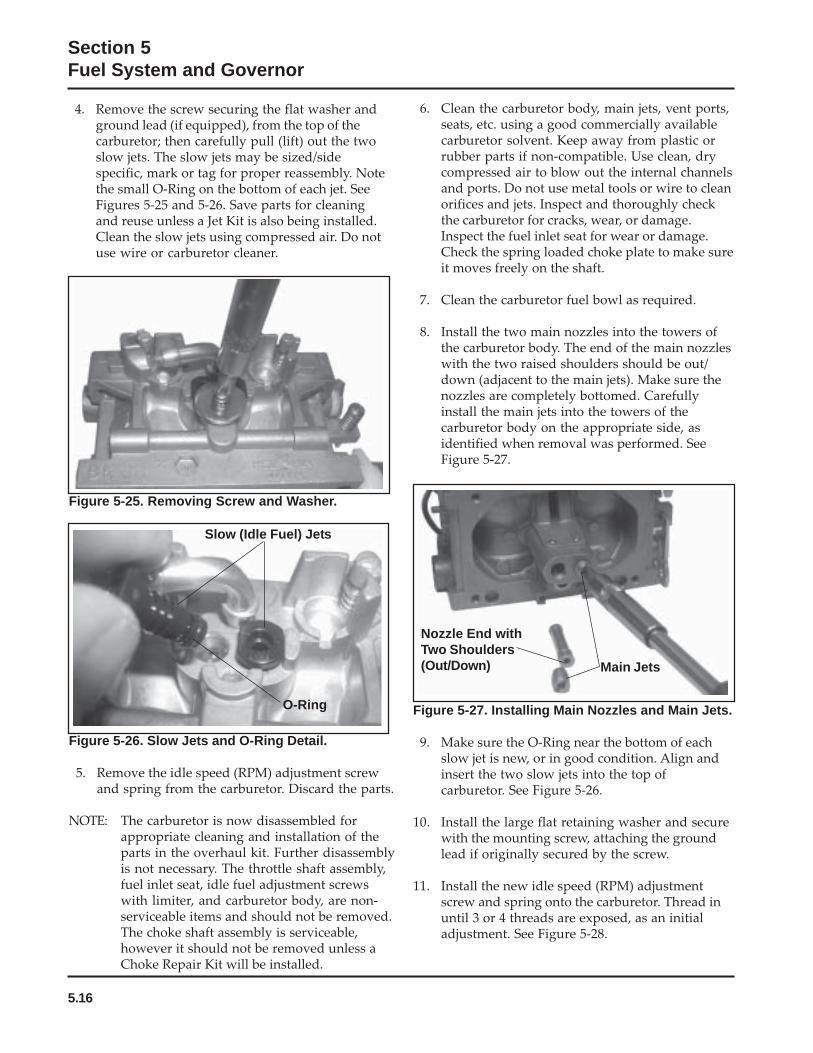
5.16
Section 5Fuel System and Governor
4. Remove the screw securing the flat washer andground lead (if equipped), from the top of thecarburetor; then carefully pull (lift) out the twoslow jets. The slow jets may be sized/sidespecific, mark or tag for proper reassembly. Notethe small O-Ring on the bottom of each jet. SeeFigures 5-25 and 5-26. Save parts for cleaningand reuse unless a Jet Kit is also being installed.Clean the slow jets using compressed air. Do notuse wire or carburetor cleaner.
6. Clean the carburetor body, main jets, vent ports,seats, etc. using a good commercially availablecarburetor solvent. Keep away from plastic orrubber parts if non-compatible. Use clean, drycompressed air to blow out the internal channelsand ports. Do not use metal tools or wire to cleanorifices and jets. Inspect and thoroughly checkthe carburetor for cracks, wear, or damage.Inspect the fuel inlet seat for wear or damage.Check the spring loaded choke plate to make sureit moves freely on the shaft.
7. Clean the carburetor fuel bowl as required.
8. Install the two main nozzles into the towers ofthe carburetor body. The end of the main nozzleswith the two raised shoulders should be out/down (adjacent to the main jets). Make sure thenozzles are completely bottomed. Carefullyinstall the main jets into the towers of thecarburetor body on the appropriate side, asidentified when removal was performed. SeeFigure 5-27.
Figure 5-25. Removing Screw and Washer.
Figure 5-26. Slow Jets and O-Ring Detail.
5. Remove the idle speed (RPM) adjustment screwand spring from the carburetor. Discard the parts.
NOTE: The carburetor is now disassembled forappropriate cleaning and installation of theparts in the overhaul kit. Further disassemblyis not necessary. The throttle shaft assembly,fuel inlet seat, idle fuel adjustment screwswith limiter, and carburetor body, are non-serviceable items and should not be removed.The choke shaft assembly is serviceable,however it should not be removed unless aChoke Repair Kit will be installed.
Slow (Idle Fuel) Jets
O-Ring Figure 5-27. Installing Main Nozzles and Main Jets.
9. Make sure the O-Ring near the bottom of eachslow jet is new, or in good condition. Align andinsert the two slow jets into the top ofcarburetor. See Figure 5-26.
10. Install the large flat retaining washer and securewith the mounting screw, attaching the groundlead if originally secured by the screw.
11. Install the new idle speed (RPM) adjustmentscrew and spring onto the carburetor. Thread inuntil 3 or 4 threads are exposed, as an initialadjustment. See Figure 5-28.
Nozzle End withTwo Shoulders(Out/Down) Main Jets
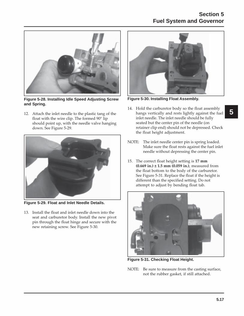
5.17
Section 5Fuel System and Governor
5
Figure 5-28. Installing Idle Speed Adjusting Screwand Spring.
12. Attach the inlet needle to the plastic tang of thefloat with the wire clip. The formed 90° lipshould point up, with the needle valve hangingdown. See Figure 5-29.
Figure 5-30. Installing Float Assembly.
14. Hold the carburetor body so the float assemblyhangs vertically and rests lightly against the fuelinlet needle. The inlet needle should be fullyseated but the center pin of the needle (onretainer clip end) should not be depressed. Checkthe float height adjustment.
NOTE: The inlet needle center pin is spring loaded.Make sure the float rests against the fuel inletneedle without depressing the center pin.
15. The correct float height setting is 17 mm(0.669 in.) ± 1.5 mm (0.059 in.), measured fromthe float bottom to the body of the carburetor.See Figure 5-31. Replace the float if the height isdifferent than the specified setting. Do notattempt to adjust by bending float tab.
Figure 5-29. Float and Inlet Needle Details.
13. Install the float and inlet needle down into theseat and carburetor body. Install the new pivotpin through the float hinge and secure with thenew retaining screw. See Figure 5-30.
Figure 5-31. Checking Float Height.
NOTE: Be sure to measure from the casting surface,not the rubber gasket, if still attached.

5.18
Section 5Fuel System and Governor
16. When the proper float height is obtained,carefully reinstall the fuel bowl, using newO-Rings onto the carburetor. Secure with thefour original screws. Torque the screws to2.5 ± 0.3 N·m (23 ± 2.6 in. lb.). See Figure 5-32.
Figure 5-34. Assembling Choke Lever.
8. Turn the old bushing upside down and use it as adriver to carefully press or tap the new bushinginto the carburetor body until it bottoms. Checkthat the choke lever pivots freely withoutrestriction or binding. See Figure 5-35.
Figure 5-33. Choke Details.
Figure 5-32. Installing Fuel Bowl.
Choke Repair1. Remove the carburetor from the engine. Discard
the old mounting gaskets for the air cleaner andcarburetor.
2. Clean the areas around the choke shaft and theself-relieving choke mechanism thoroughly.
3. Remove and discard the plastic cap from the endof the choke lever/shaft assembly.
4. Note the position of the spring legs and the chokeplate for correct reassembly later. See Figure5-33. Remove the two screws attaching the chokeplate to the choke shaft. Pull the shaft out of thecarburetor body and discard the removed parts.
5. Use a screw extractor (easy-out) and remove theoriginal choke shaft bushing with the old chokelever from the carburetor housing. Save thebushing to use as a driver for installing the newbushing. Discard the old lever.
6. Clean the I.D. of both choke shaft bores asrequired.
7. Insert the new bushing through the new chokelever from the outside, and start the bushing inthe outer shaft bore. Position the choke lever sothe protruding boss on the carburetor housing isbetween the two stops formed in the choke lever.See Figure 5-34.
Figure 5-35. Installing Bushing.
StopsBoss
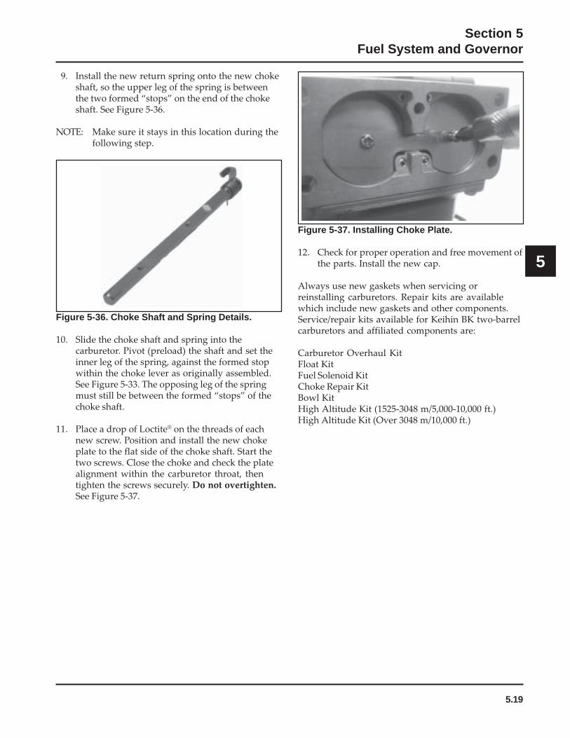
5.19
Section 5Fuel System and Governor
5
Figure 5-36. Choke Shaft and Spring Details.
10. Slide the choke shaft and spring into thecarburetor. Pivot (preload) the shaft and set theinner leg of the spring, against the formed stopwithin the choke lever as originally assembled.See Figure 5-33. The opposing leg of the springmust still be between the formed “stops” of thechoke shaft.
11. Place a drop of Loctite® on the threads of eachnew screw. Position and install the new chokeplate to the flat side of the choke shaft. Start thetwo screws. Close the choke and check the platealignment within the carburetor throat, thentighten the screws securely. Do not overtighten.See Figure 5-37.
9. Install the new return spring onto the new chokeshaft, so the upper leg of the spring is betweenthe two formed “stops” on the end of the chokeshaft. See Figure 5-36.
NOTE: Make sure it stays in this location during thefollowing step.
Figure 5-37. Installing Choke Plate.
12. Check for proper operation and free movement ofthe parts. Install the new cap.
Always use new gaskets when servicing orreinstalling carburetors. Repair kits are availablewhich include new gaskets and other components.Service/repair kits available for Keihin BK two-barrelcarburetors and affiliated components are:
Carburetor Overhaul KitFloat KitFuel Solenoid KitChoke Repair KitBowl KitHigh Altitude Kit (1525-3048 m/5,000-10,000 ft.)High Altitude Kit (Over 3048 m/10,000 ft.)
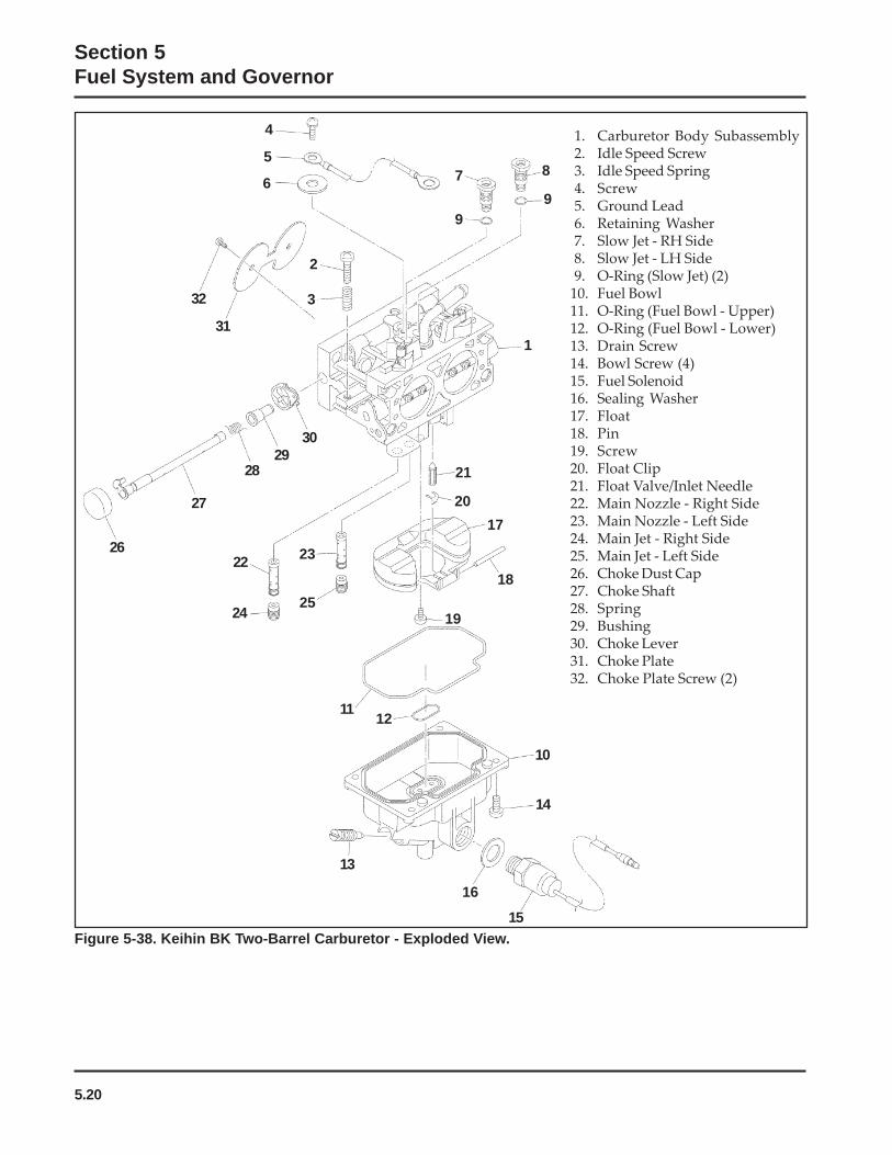
5.20
Section 5Fuel System and Governor
Figure 5-38. Keihin BK Two-Barrel Carburetor - Exploded View.
1
10
17
20
21
18
1925
12
23
11
14
13
7
24
9
4
2
3
26
15
16
6
5
31
32
27
2829
8
9
22
30
1. Carburetor Body Subassembly2. Idle Speed Screw3. Idle Speed Spring4. Screw5. Ground Lead6. Retaining Washer7. Slow Jet - RH Side 8. Slow Jet - LH Side9. O-Ring (Slow Jet) (2)
10. Fuel Bowl 11. O-Ring (Fuel Bowl - Upper) 12. O-Ring (Fuel Bowl - Lower) 13. Drain Screw 14. Bowl Screw (4) 15. Fuel Solenoid 16. Sealing Washer 17. Float 18. Pin 19. Screw 20. Float Clip 21. Float Valve/Inlet Needle 22. Main Nozzle - Right Side 23. Main Nozzle - Left Side 24. Main Jet - Right Side 25. Main Jet - Left Side 26. Choke Dust Cap 27. Choke Shaft 28. Spring 29. Bushing 30. Choke Lever 31. Choke Plate 32. Choke Plate Screw (2)
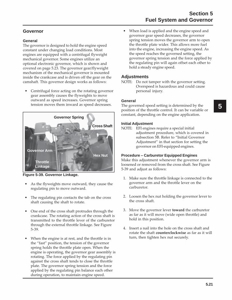
5.21
Section 5Fuel System and Governor
5
Figure 5-39. Governor Linkage.
• As the flyweights move outward, they cause theregulating pin to move outward.
• The regulating pin contacts the tab on the crossshaft causing the shaft to rotate.
• One end of the cross shaft protrudes through thecrankcase. The rotating action of the cross shaft istransmitted to the throttle lever of the carburetorthrough the external throttle linkage. See Figure5-39.
• When the engine is at rest, and the throttle is inthe “fast” position, the tension of the governorspring holds the throttle plate open. When theengine is operating, the governor gear assembly isrotating. The force applied by the regulating pinagainst the cross shaft tends to close the throttleplate. The governor spring tension and the forceapplied by the regulating pin balance each otherduring operation, to maintain engine speed.
Governor Spring
Governor Arm
ThrottleLinkage
Hex Nut
Cross Shaft
Governor
GeneralThe governor is designed to hold the engine speedconstant under changing load conditions. Mostengines are equipped with a centrifugal flyweightmechanical governor. Some engines utilize anoptional electronic governor, which is shown andcovered on page 5.23. The governor gear/flyweightmechanism of the mechanical governor is mountedinside the crankcase and is driven off the gear on thecamshaft. This governor design works as follows:
• Centrifugal force acting on the rotating governorgear assembly causes the flyweights to moveoutward as speed increases. Governor springtension moves them inward as speed decreases.
• When load is applied and the engine speed andgovernor gear speed decreases, the governorspring tension moves the governor arm to openthe throttle plate wider. This allows more fuelinto the engine, increasing the engine speed. Asthe speed reaches the governed setting, thegovernor spring tension and the force applied bythe regulating pin will again offset each other tohold a steady engine speed.
AdjustmentsNOTE: Do not tamper with the governor setting.
Overspeed is hazardous and could causepersonal injury.
GeneralThe governed speed setting is determined by theposition of the throttle control. It can be variable orconstant, depending on the engine application.
Initial AdjustmentNOTE: EFI engines require a special initial
adjustment procedure, which is covered insubsection 5B. Refer to “Initial GovernorAdjustment” in that section for setting thegovernor on EFI-equipped engines.
Procedure – Carburetor Equipped EnginesMake this adjustment whenever the governor arm isloosened or removed from the cross shaft. See Figure5-39 and adjust as follows:
1. Make sure the throttle linkage is connected to thegovernor arm and the throttle lever on thecarburetor.
2. Loosen the hex nut holding the governor lever tothe cross shaft.
3. Move the governor lever toward the carburetoras far as it will move (wide open throttle) andhold in this position.
4. Insert a nail into the hole on the cross shaft androtate the shaft counterclockwise as far as it willturn, then tighten hex nut securely.

5.22
Section 5Fuel System and Governor
Figure 5-41. Governor Control Connections.
Choke Control Cable
ThrottleControlCable
Kill Switch
Choke Control Lever #1
Throttle Control Lever #2
Choke Linkage
Z Bend
Throttle Control Cable
ChokeControlCable
Right Side PullHigh SpeedControl Lever
High SpeedAdjustingScrew
Dual Control HighSpeed Lever Stop Screw"Do Not Remove"
Kill Switch Adjusting Screw
Left Side Pull
Sensitivity AdjustmentGovernor sensitivity is adjusted by repositioning thegovernor spring in the holes of the governor lever. Ifspeed surging occurs with a change in engine load, thegovernor is set too sensitive. If a big drop in speedoccurs when normal load is applied, the governorshould be set for greater sensitivity. See Figure 5-40and adjust as follows:
1. To increase the sensitivity, move the spring closerto the governor cross shaft.
2. To decrease the sensitivity, move the springaway from the governor cross shaft.
High Speed (RPM) Adjustment (Refer to Figure 5-41.)1. With the engine running, move the throttle
control to fast. Use a tachometer to check theRPM speed.
2. Loosen the lock nut on high speed adjustingscrew. Turn the screw outward to decrease, orinward to increase the RPM speed. Check RPMwith a tachometer.
3. When the desired RPM speed is obtained,retighten the lock nut.
NOTE: When the throttle and choke control cablesare routed side-by-side, especially under asingle clamp, there must be a small gapbetween the cables to prevent internalbinding. After the high-speed setting hasbeen completed, check that there is a gap ofat least 0.5 mm (0.020 in.) between thecontrol cables.
Figure 5-40. Governor Sensitivity Adjustments.
GovernorLever

5.23
Section 5Fuel System and Governor
5
Figure 5-43. Electronic Governor Assembly.
Digital Linear Actuator (DLA)Energizing the bi-directional digital linear actuatorcoils in the proper sequence, causes the threaded shaftto move out of, or back into the rotor, in precise linearincrements. When power is removed, the actuatorshaft remains in position. The DLA must initialize(fully extend) to move the throttle plate to the closedposition, and partially open for starting. Correctadjustment of the DLA is critical to achieve the fullrange of throttle plate movement. See AdjustmentProcedure.
1 2 3 4 5
Figure 5-42. Electronic Governor Assembly.
1. Digital Linear Actuator2. Throttle Linkage3. Linkage Spring4. Choke Linkage5. Throttle Lever Adapter
Governor Control Unit
Electronic Governor
GeneralThe electronic governor regulates engine speed atvarying loads. It consists of a governor control unit,digital linear actuator and linkage.
Governor Control Unit (GCU) senses engine speed bypulse voltage inputs from the ignition modules. TheGCU regulates the engine speed by variable inputvoltage from a customer-supplied potentiometer or asingle pole, single throw (SPST) switch.
Potentiometer Specifications:
1860 low speed endpointvariable speed endpoint3600 high speed endpoint
Wiper Voltage
0-11-99-16
Engine Speed (RPM)
1860 low speed endpoint3600 high speed endpoint
Engine Speed (RPM)Switch Position
OpenClosed
SPST Switch Specifications:
GCU Safety FeaturesIn the event of an engine overspeed condition, theGCU will shut down the engine by grounding theignition modules.
The GCU will shut down the engine by grounding theignition when power to the GCU is lost.
LinkageThe throttle linkage spring will fully open the throttleplate if the linkage becomes detached from the DLA.This will create an overspeed condition causing theengine to shut down. The DLA shaft will have to bemanually screwed back into the body, and thenretracted before reassembling the linkage.
Adjustment ProcedureThe DLA must be in the fully retracted positionduring assembly. The full range of throttle platemovement will not be achieved if the DLA is partiallyextended when assembled. Loosen the two DLAmounting plate screws located on the top of theactuator plate. With the throttle linkage centered inthe U-Clip at the end of the DLA shaft, slide the DLAbracket assembly back until the throttle plate is fullyopen. Torque the mounting plate screws to 2.5 N·m(22 in. lb.).
5.24
Section 5Fuel System and Governor
Troubleshooting ProcedureEngine starts, but will not continue to run
1. Check the linkage connection between the DLAand throttle plate.
2. Verify the DLA initializes when power issupplied (key switch in the start or run position).
3. Test the potentiometer wiper output voltage (ifequipped).
4. Test the SPST switch (if equipped).
5. Check the wire harness and connections.
Engine does not run at the expected speed1. Check to see that the throttle linkage and DLA
have full range of motion having no mechanicalinterference.
2. Test the potentiometer wiper voltage (ifequipped).
3. Test the SPST switch (if equipped).
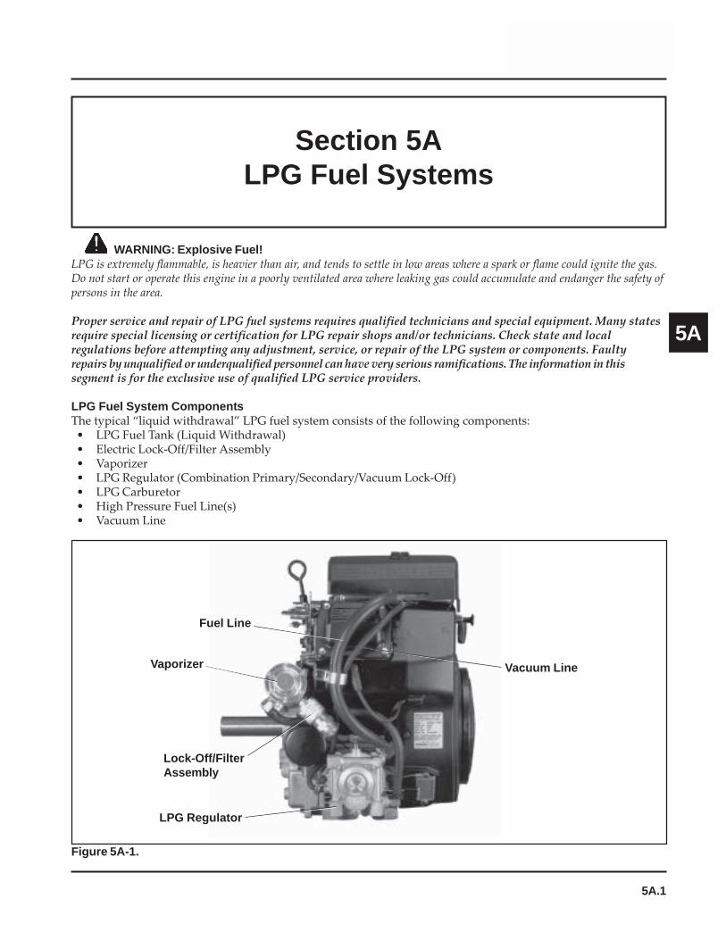
5A.1
Section 5ALPG Fuel Systems
5A
Section 5ALPG Fuel Systems
Figure 5A-1.
Vacuum LineVaporizer
Lock-Off/FilterAssembly
LPG Regulator
Fuel Line
WARNING: Explosive Fuel!LPG is extremely flammable, is heavier than air, and tends to settle in low areas where a spark or flame could ignite the gas.Do not start or operate this engine in a poorly ventilated area where leaking gas could accumulate and endanger the safety ofpersons in the area.
Proper service and repair of LPG fuel systems requires qualified technicians and special equipment. Many statesrequire special licensing or certification for LPG repair shops and/or technicians. Check state and localregulations before attempting any adjustment, service, or repair of the LPG system or components. Faultyrepairs by unqualified or underqualified personnel can have very serious ramifications. The information in thissegment is for the exclusive use of qualified LPG service providers.
LPG Fuel System ComponentsThe typical “liquid withdrawal” LPG fuel system consists of the following components:• LPG Fuel Tank (Liquid Withdrawal)• Electric Lock-Off/Filter Assembly• Vaporizer• LPG Regulator (Combination Primary/Secondary/Vacuum Lock-Off)• LPG Carburetor• High Pressure Fuel Line(s)• Vacuum Line
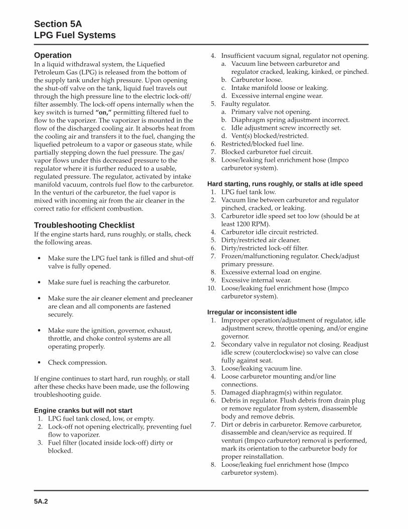
5A.2
Section 5ALPG Fuel Systems
OperationIn a liquid withdrawal system, the LiquefiedPetroleum Gas (LPG) is released from the bottom ofthe supply tank under high pressure. Upon openingthe shut-off valve on the tank, liquid fuel travels outthrough the high pressure line to the electric lock-off/filter assembly. The lock-off opens internally when thekey switch is turned “on,” permitting filtered fuel toflow to the vaporizer. The vaporizer is mounted in theflow of the discharged cooling air. It absorbs heat fromthe cooling air and transfers it to the fuel, changing theliquefied petroleum to a vapor or gaseous state, whilepartially stepping down the fuel pressure. The gas/vapor flows under this decreased pressure to theregulator where it is further reduced to a usable,regulated pressure. The regulator, activated by intakemanifold vacuum, controls fuel flow to the carburetor.In the venturi of the carburetor, the fuel vapor ismixed with incoming air from the air cleaner in thecorrect ratio for efficient combustion.
Troubleshooting ChecklistIf the engine starts hard, runs roughly, or stalls, checkthe following areas.
• Make sure the LPG fuel tank is filled and shut-offvalve is fully opened.
• Make sure fuel is reaching the carburetor.
• Make sure the air cleaner element and precleanerare clean and all components are fastenedsecurely.
• Make sure the ignition, governor, exhaust,throttle, and choke control systems are alloperating properly.
• Check compression.
If engine continues to start hard, run roughly, or stallafter these checks have been made, use the followingtroubleshooting guide.
Engine cranks but will not start1. LPG fuel tank closed, low, or empty.2. Lock-off not opening electrically, preventing fuel
flow to vaporizer.3. Fuel filter (located inside lock-off) dirty or
blocked.
4. Insufficient vacuum signal, regulator not opening.a. Vacuum line between carburetor and
regulator cracked, leaking, kinked, or pinched.b. Carburetor loose.c. Intake manifold loose or leaking.d. Excessive internal engine wear.
5. Faulty regulator.a. Primary valve not opening.b. Diaphragm spring adjustment incorrect.c. Idle adjustment screw incorrectly set.d. Vent(s) blocked/restricted.
6. Restricted/blocked fuel line.7. Blocked carburetor fuel circuit.8. Loose/leaking fuel enrichment hose (Impco
carburetor system).
Hard starting, runs roughly, or stalls at idle speed1. LPG fuel tank low.2. Vacuum line between carburetor and regulator
pinched, cracked, or leaking.3. Carburetor idle speed set too low (should be at
least 1200 RPM).4. Carburetor idle circuit restricted.5. Dirty/restricted air cleaner.6. Dirty/restricted lock-off filter.7. Frozen/malfunctioning regulator. Check/adjust
primary pressure.8. Excessive external load on engine.9. Excessive internal wear.
10. Loose/leaking fuel enrichment hose (Impcocarburetor system).
Irregular or inconsistent idle1. Improper operation/adjustment of regulator, idle
adjustment screw, throttle opening, and/or enginegovernor.
2. Secondary valve in regulator not closing. Readjustidle screw (couterclockwise) so valve can closefully against seat.
3. Loose/leaking vacuum line.4. Loose carburetor mounting and/or line
connections.5. Damaged diaphragm(s) within regulator.6. Debris in regulator. Flush debris from drain plug
or remove regulator from system, disassemblebody and remove debris.
7. Dirt or debris in carburetor. Remove carburetor,disassemble and clean/service as required. Ifventuri (Impco carburetor) removal is performed,mark its orientation to the carburetor body forproper reinstallation.
8. Loose/leaking fuel enrichment hose (Impcocarburetor system).
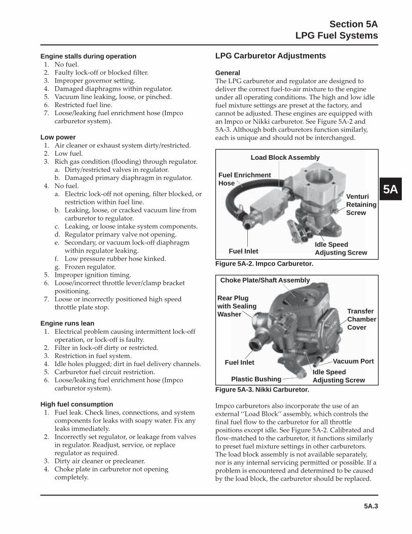
5A.3
Section 5ALPG Fuel Systems
5A
Engine stalls during operation1. No fuel.2. Faulty lock-off or blocked filter.3. Improper governor setting.4. Damaged diaphragms within regulator.5. Vacuum line leaking, loose, or pinched.6. Restricted fuel line.7. Loose/leaking fuel enrichment hose (Impco
carburetor system).
Low power1. Air cleaner or exhaust system dirty/restricted.2. Low fuel.3. Rich gas condition (flooding) through regulator.
a. Dirty/restricted valves in regulator.b. Damaged primary diaphragm in regulator.
4. No fuel.a. Electric lock-off not opening, filter blocked, or
restriction within fuel line.b. Leaking, loose, or cracked vacuum line from
carburetor to regulator.c. Leaking, or loose intake system components.d. Regulator primary valve not opening.e. Secondary, or vacuum lock-off diaphragm
within regulator leaking.f. Low pressure rubber hose kinked.g. Frozen regulator.
5. Improper ignition timing.6. Loose/incorrect throttle lever/clamp bracket
positioning.7. Loose or incorrectly positioned high speed
throttle plate stop.
Engine runs lean1. Electrical problem causing intermittent lock-off
operation, or lock-off is faulty.2. Filter in lock-off dirty or restricted.3. Restriction in fuel system.4. Idle holes plugged; dirt in fuel delivery channels.5. Carburetor fuel circuit restriction.6. Loose/leaking fuel enrichment hose (Impco
carburetor system).
High fuel consumption1. Fuel leak. Check lines, connections, and system
components for leaks with soapy water. Fix anyleaks immediately.
2. Incorrectly set regulator, or leakage from valvesin regulator. Readjust, service, or replaceregulator as required.
3. Dirty air cleaner or precleaner.4. Choke plate in carburetor not opening
completely.
LPG Carburetor Adjustments
GeneralThe LPG carburetor and regulator are designed todeliver the correct fuel-to-air mixture to the engineunder all operating conditions. The high and low idlefuel mixture settings are preset at the factory, andcannot be adjusted. These engines are equipped withan Impco or Nikki carburetor. See Figure 5A-2 and5A-3. Although both carburetors function similarly,each is unique and should not be interchanged.
Figure 5A-2. Impco Carburetor.
Figure 5A-3. Nikki Carburetor.
Impco carburetors also incorporate the use of anexternal ‘‘Load Block’’ assembly, which controls thefinal fuel flow to the carburetor for all throttlepositions except idle. See Figure 5A-2. Calibrated andflow-matched to the carburetor, it functions similarlyto preset fuel mixture settings in other carburetors.The load block assembly is not available separately,nor is any internal servicing permitted or possible. If aproblem is encountered and determined to be causedby the load block, the carburetor should be replaced.
Rear Plugwith SealingWasher
Choke Plate/Shaft Assembly
Fuel Inlet
Plastic Bushing
TransferChamberCover
Vacuum Port
Idle SpeedAdjusting Screw
Load Block Assembly
Fuel EnrichmentHose
Fuel Inlet
VenturiRetainingScrew
Idle SpeedAdjusting Screw

5A.4
Section 5ALPG Fuel Systems
High Altitude OperationThe standard carburetor calibrations will provideproper operation up to altitudes of 1500 m (5000 ft.).No internal changes are necessary or available foreither carburetor.
NOTE: Carburetor adjustments should be made onlyafter the engine has warmed up.
Idle Speed Adjustment1. Start the engine and run at half throttle for 5 to 10
minutes. Check that the throttle and choke (Nikkicarburetor) plates can open fully.
2. Place the throttle control into the “idle” or“slow” position. Turn the low idle speedadjusting screw (See Figure 5A-2 or 5A-3) in orout, to obtain a low idle speed of 1200 RPM (± 75RPM), or set to application specifications. Checkthe speed using a tachometer.
NOTE: The actual low idle speed (RPM) depends onthe application. Refer to the equipmentmanufacturer’s recommendations. The lowidle speed for basic engines is 1200 RPM.
LPG Fuel System Component Service
LPG Carburetor - CleaningThe carburetor may be cleaned if necessary. Removalfrom the engine and limited disassembly will aid incleaning.
NOTE: Impco Carburetor: Do not loosen or alter themounted position of the clamping bracketsand/or stop collar on the throttle shaft. Eachis preset, in correlation to a specific positionof the throttle plate (shaft), or acts as a stop.None of these attached components,including the throttle plate or shaft, requiresdisassembly or removal for any carburetorservicing. All the components on the throttleshaft should be left intact. If the settings ofany one of these is inadvertently loosened oraltered, each must be checked/reset, orperformance and operation will be affected.Refer to the procedure included in thereassembly/installation sequence to check orreset.
Impco Carburetor1. Turn off fuel supply at tank.
2. Remove the air cleaner, breather hose, fuel line,vacuum hose, choke, and throttle linkages.Remove the mounting hardware, carburetor, andgaskets from the engine. Discard the gaskets.
3. The carburetor venturi may be removed forinspection and appropriate cleaning.
a. Remove the four screws securing the aircleaner adapter and gasket to the carburetor.See Figure 5A-4.
Figure 5A-4.
b. Important: Mark a small line on the outeredge of the venturi for proper orientation andreinstallation later.
c. Loosen the venturi retaining screw on the sideof the carburetor body and lift out theventuri. See Figure 5A-5.
Figure 5A-5.
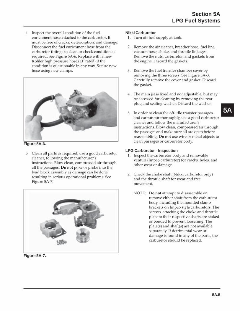
5A.5
Section 5ALPG Fuel Systems
5A
4. Inspect the overall condition of the fuelenrichment hose attached to the carburetor. Itmust be free of cracks, deterioration, and damage.Disconnect the fuel enrichment hose from thecarburetor fittings to clean or check condition asrequired. See Figure 5A-6. Replace with a newKohler high pressure hose (LP rated) if thecondition is questionable in any way. Secure newhose using new clamps.
Figure 5A-6.
5. Clean all parts as required, use a good carburetorcleaner, following the manufacturer'sinstructions. Blow clean, compressed air throughall the passages. Do not poke or probe into theload block assembly as damage can be done,resulting in serious operational problems. SeeFigure 5A-7.
Figure 5A-7.
Nikki Carburetor1. Turn off fuel supply at tank.
2. Remove the air cleaner, breather hose, fuel line,vacuum hose, choke, and throttle linkages.Remove the nuts, carburetor, and gaskets fromthe engine. Discard the gaskets.
3. Remove the fuel transfer chamber cover byremoving the three screws. See Figure 5A-3.Carefully remove the cover and gasket. Discardthe gasket.
4. The main jet is fixed and nonadjustable, but maybe accessed for cleaning by removing the rearplug and sealing washer. Discard the washer.
5. In order to clean the off-idle transfer passagesand carburetor thoroughly, use a good carburetorcleaner and follow the manufacturer'sinstructions. Blow clean, compressed air throughthe passages and make sure all are open beforereassembling. Do not use wire or metal objects toclean passages or carburetor body.
LPG Carburetor - Inspection1. Inspect the carburetor body and removable
venturi (Impco carburetor) for cracks, holes, andother wear or damage.
2. Check the choke shaft (Nikki carburetor only)and the throttle shaft for wear and freemovement.
NOTE: Do not attempt to disassemble orremove either shaft from the carburetorbody, including the mounted clampbrackets on Impco style carburetors. Thescrews, attaching the choke and throttleplate to their respective shafts are stakedor bonded to prevent loosening. Theplate(s) and shaft(s) are not availableseparately. If detrimental wear ordamage is found in any of the parts, thecarburetor should be replaced.

5A.6
Section 5ALPG Fuel Systems
LPG Carburetor - Reassembly
Impco Carburetor1. Slide the venturi into the carburetor body,
aligning the position mark made prior toremoval. Correctly installed, the discharge holesshould not be visible from the top.
2. Secure with the venturi retaining screw. Torquethe screw to 4.0 N·m (36 in. lb.).
3. Install a new adapter gasket and mount the aircleaner adapter onto the carburetor with the fourscrews. Torque the screws to 4.0 N·m (36 in. lb.).
4. Install a new carburetor gasket onto the intakemanifold adapter, followed by the carburetor.Install and finger tighten the mounting fasteners.
5. Connect the ‘‘Z’’ end of the throttle linkage andthe dampening spring to the throttle clampbracket on the throttle shaft. Attach the oppositeend of linkage and spring to the governor lever.
NOTE: The clamp brackets and stop collarmounted on the throttle shaft should stillbe in their original positions (See Figure5A-2), and not require any readjustment/resetting. Continue with steps 6 and 7. Ifthe mounted position of any one of thesewas affected or changed, it will benecessary to check and reset the positionof each before proceeding. Follow thecomplete instructions listed after step 7,then continue with steps 6 and 7.
6. Manually move the governor lever toward thecarburetor as far as it will go.
7. Check that the throttle plate is now fully open orreposition the carburetor slightly on themounting screws so it is fully open. Torque themounting screws to 9.9 N·m (88 in. lb.).
Instructions for Checking/Positioning the ClampBrackets Mounted on the Throttle ShaftUse only if the position or mounting of the clampbracket(s) has been disturbed. Figures show thecarburetor removed from the engine for clarity.
Figure 5A-8. Backing Off Idle Speed Screw.
2. Loosen the clamp bracket mounting screw, andpivot the throttle shaft to fully close the throttleplate. See Figure 5A-9.
Figure 5A-9. Closing Throttle Plate.
3. Hold the throttle plate closed and rotate theclamp bracket until the end of the screw contactsthe stop. Insert a 0.025 mm (0.001 in.) feeler gaugebetween the carburetor housing and the side ofthe clamp bracket to set the endplay, then tightenthe mounting screw securely. See Figure 5A-10.
Idle Speed Clamp Bracket Position1. Counting the number of turns, back the idle
speed adjustment screw off (counterclockwise),so only 1 to 1 1/2 of the threads are visible. SeeFigure 5A-8.
Idle SpeedClampBracketMountingScrew
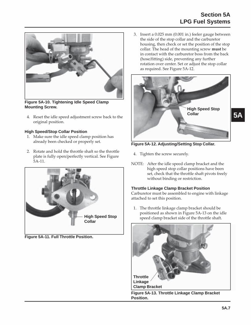
5A.7
Section 5ALPG Fuel Systems
5A
3. Insert a 0.025 mm (0.001 in.) feeler gauge betweenthe side of the stop collar and the carburetorhousing, then check or set the position of the stopcollar. The head of the mounting screw must bein contact with the carburetor boss from the back(hose/fitting) side, preventing any furtherrotation over center. Set or adjust the stop collaras required. See Figure 5A-12.
Figure 5A-12. Adjusting/Setting Stop Collar.
4. Tighten the screw securely.
NOTE: After the idle speed clamp bracket and thehigh speed stop collar positions have beenset, check that the throttle shaft pivots freelywithout binding or restriction.
Throttle Linkage Clamp Bracket PositionCarburetor must be assembled to engine with linkageattached to set this position.
1. The throttle linkage clamp bracket should bepositioned as shown in Figure 5A-13 on the idlespeed clamp bracket side of the throttle shaft.
Figure 5A-13. Throttle Linkage Clamp BracketPosition.
Figure 5A-10. Tightening Idle Speed ClampMounting Screw.
4. Reset the idle speed adjustment screw back to theoriginal position.
High Speed/Stop Collar Position1. Make sure the idle speed clamp position has
already been checked or properly set.
2. Rotate and hold the throttle shaft so the throttleplate is fully open/perfectly vertical. See Figure5A-11.
Figure 5A-11. Full Throttle Position.
High Speed StopCollar
High Speed StopCollar
ThrottleLinkageClamp Bracket
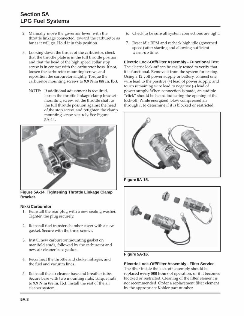
5A.8
Section 5ALPG Fuel Systems
2. Manually move the governor lever, with thethrottle linkage connected, toward the carburetor asfar as it will go. Hold it in this position.
3. Looking down the throat of the carburetor, checkthat the throttle plate is in the full throttle positionand that the head of the high speed collar stopscrew is in contact with the carburetor boss. If not,loosen the carburetor mounting screws andreposition the carburetor slightly. Torque thecarburetor mounting screws to 9.9 N·m (88 in. lb.).
NOTE: If additional adjustment is required,loosen the throttle linkage clamp bracketmounting screw, set the throttle shaft tothe full throttle position against the headof the stop screw, and retighten the clampmounting screw securely. See Figure5A-14.
Figure 5A-14. Tightening Throttle Linkage ClampBracket.
Nikki Carburetor1. Reinstall the rear plug with a new sealing washer.
Tighten the plug securely.
2. Reinstall fuel transfer chamber cover with a newgasket. Secure with the three screws.
3. Install new carburetor mounting gasket onmanifold studs, followed by the carburetor andnew air cleaner base gasket.
4. Reconnect the throttle and choke linkages, andthe fuel and vacuum lines.
5. Reinstall the air cleaner base and breather tube.Secure base with two mounting nuts. Torque nutsto 9.9 N·m (88 in. lb.). Install the rest of the aircleaner system.
6. Check to be sure all system connections are tight.
7. Reset idle RPM and recheck high idle (governedspeed) after starting and allowing sufficientwarm-up time.
Electric Lock-Off/Filter Assembly - Functional TestThe electric lock-off can be easily tested to verify thatit is functional. Remove it from the system for testing.Using a 12 volt power supply or battery, connect onewire lead to the positive (+) lead of power supply, andtouch remaining wire lead to negative (-) lead ofpower supply. When connection is made, an audible“click” should be heard indicating the opening of thelock-off. While energized, blow compressed airthrough it to determine if it is blocked or restricted.
Figure 5A-15.
Figure 5A-16.
Electric Lock-Off/Filter Assembly - Filter ServiceThe filter inside the lock-off assembly should bereplaced every 500 hours of operation, or if it becomesblocked or restricted. Cleaning of the filter element isnot recommended. Order a replacement filter elementby the appropriate Kohler part number.
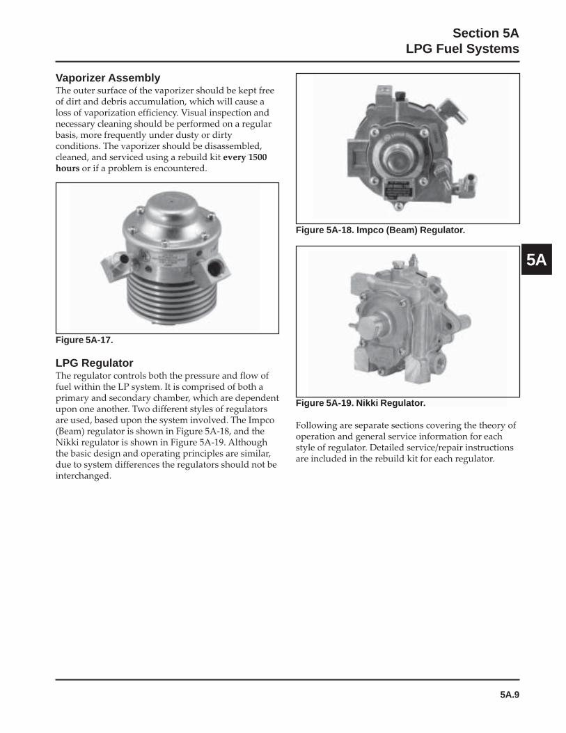
5A.9
Section 5ALPG Fuel Systems
5A
Vaporizer AssemblyThe outer surface of the vaporizer should be kept freeof dirt and debris accumulation, which will cause aloss of vaporization efficiency. Visual inspection andnecessary cleaning should be performed on a regularbasis, more frequently under dusty or dirtyconditions. The vaporizer should be disassembled,cleaned, and serviced using a rebuild kit every 1500hours or if a problem is encountered.
Figure 5A-17.
LPG RegulatorThe regulator controls both the pressure and flow offuel within the LP system. It is comprised of both aprimary and secondary chamber, which are dependentupon one another. Two different styles of regulatorsare used, based upon the system involved. The Impco(Beam) regulator is shown in Figure 5A-18, and theNikki regulator is shown in Figure 5A-19. Althoughthe basic design and operating principles are similar,due to system differences the regulators should not beinterchanged.
Figure 5A-18. Impco (Beam) Regulator.
Figure 5A-19. Nikki Regulator.
Following are separate sections covering the theory ofoperation and general service information for eachstyle of regulator. Detailed service/repair instructionsare included in the rebuild kit for each regulator.
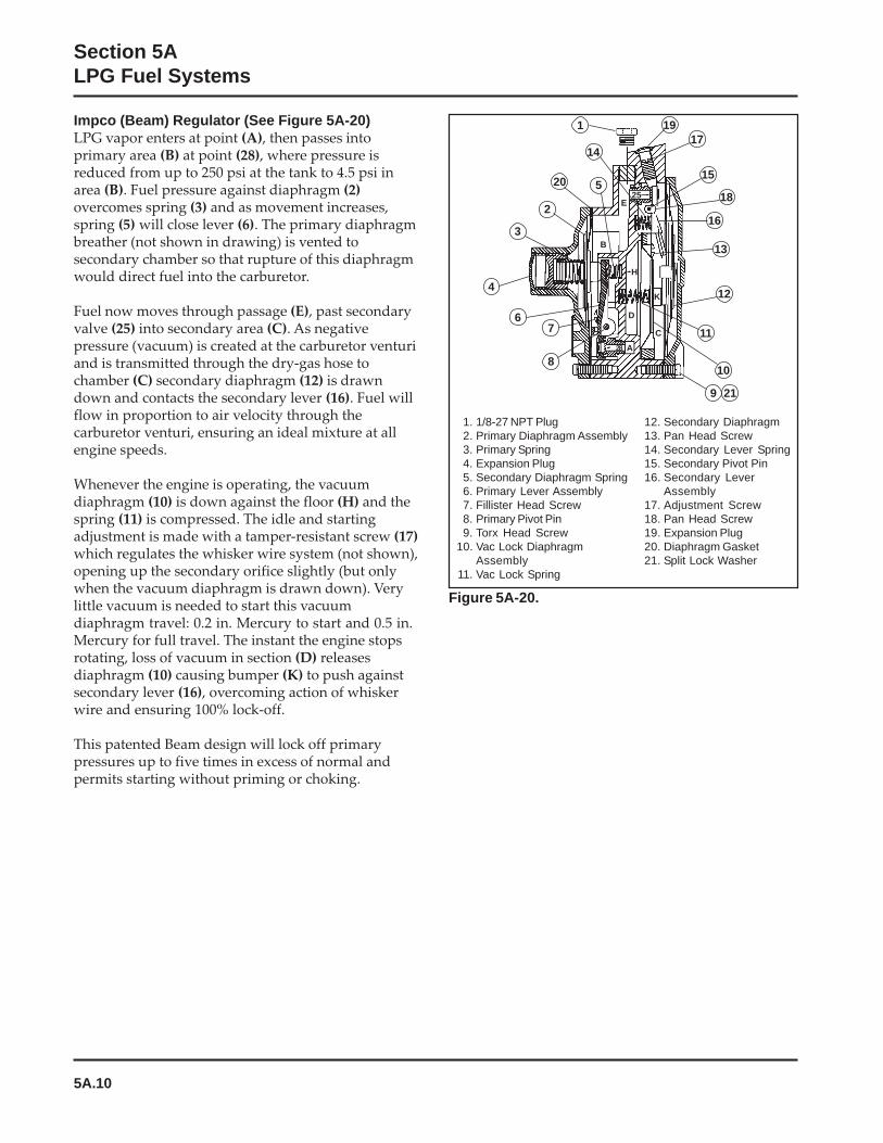
5A.10
Section 5ALPG Fuel Systems
Impco (Beam) Regulator (See Figure 5A-20)LPG vapor enters at point (A), then passes intoprimary area (B) at point (28), where pressure isreduced from up to 250 psi at the tank to 4.5 psi inarea (B). Fuel pressure against diaphragm (2)overcomes spring (3) and as movement increases,spring (5) will close lever (6). The primary diaphragmbreather (not shown in drawing) is vented tosecondary chamber so that rupture of this diaphragmwould direct fuel into the carburetor.
Fuel now moves through passage (E), past secondaryvalve (25) into secondary area (C). As negativepressure (vacuum) is created at the carburetor venturiand is transmitted through the dry-gas hose tochamber (C) secondary diaphragm (12) is drawndown and contacts the secondary lever (16). Fuel willflow in proportion to air velocity through thecarburetor venturi, ensuring an ideal mixture at allengine speeds.
Whenever the engine is operating, the vacuumdiaphragm (10) is down against the floor (H) and thespring (11) is compressed. The idle and startingadjustment is made with a tamper-resistant screw (17)which regulates the whisker wire system (not shown),opening up the secondary orifice slightly (but onlywhen the vacuum diaphragm is drawn down). Verylittle vacuum is needed to start this vacuumdiaphragm travel: 0.2 in. Mercury to start and 0.5 in.Mercury for full travel. The instant the engine stopsrotating, loss of vacuum in section (D) releasesdiaphragm (10) causing bumper (K) to push againstsecondary lever (16), overcoming action of whiskerwire and ensuring 100% lock-off.
This patented Beam design will lock off primarypressures up to five times in excess of normal andpermits starting without priming or choking.
Figure 5A-20.
1 1917
15
18
16
13
12
11
10
9 21
8
76
4
3
2
520
14
25E
B
H
D
K
C
A28
1. 1/8-27 NPT Plug2. Primary Diaphragm Assembly3. Primary Spring4. Expansion Plug5. Secondary Diaphragm Spring6. Primary Lever Assembly7. Fillister Head Screw8. Primary Pivot Pin9. Torx Head Screw
10. Vac Lock DiaphragmAssembly
11. Vac Lock Spring
12. Secondary Diaphragm13. Pan Head Screw14. Secondary Lever Spring15. Secondary Pivot Pin16. Secondary Lever
Assembly17. Adjustment Screw18. Pan Head Screw19. Expansion Plug20. Diaphragm Gasket21. Split Lock Washer

5A.11
Section 5ALPG Fuel Systems
5A
Nikki Regulator Primary Chamber(See Figure 5A-21)The primary chamber reduces the high pressure fuelflow from the tank and vaporizer down toapproximately 4 psi. Fuel flowing from the vaporizerenters the inlet of the regulator under approximately76 kPa (11 psi) of pressure. There it is delivered to theprimary chamber (3) through the clearance betweenthe primary valve (1) and valve seat (2). As fuelcontinues to flow and the primary chamberapproaches 29 kPa (4 psi), the primary diaphragm (4)overcomes the tension of the diaphragm spring (5). Asthe diaphragm (4) and contact button (6) move up, theprimary lever spring (8) pushes the primary lever (7)up, in turn closing the primary valve (1) and stoppingthe flow of fuel. As fuel is consumed and the pressurein the primary chamber drops below 29 kPa (4 psi), thediaphragm spring (5) tension will be greater than thefuel pressure, causing the primary diaphragm (4) to bepushed down. This causes the contact button (6), topush the primary lever (7) down, in turn opening theprimary valve (1) and admitting more fuel. In thismanner, the pressure within the primary chamber ismaintained at a relatively constant 29 kPa (4 psi).
Nikki Regulator Secondary Chamber(See Figure 5A-22)The secondary chamber further reduces the fuelpressure from the 29 kPa (4 psi) of the primarychamber to near 0 kPa (0 psi) pressure, to preventexcessive fuel flow to the carburetor. Fuel enters thesecondary chamber (13) through the clearancebetween the secondary valve (11) and the valve seat(12). While the engine is operating, and fuel is beingdrawn from the secondary chamber, the secondarydiaphragm (14) is raised by atmospheric pressure,simultaneously lifting the secondary valve lever (16),opening the secondary valve (11), allowing fuel toflow. When the engine is running at idle, there maynot be enough vacuum created in the carburetorventuri to overcome the tension of the secondarydiaphragm spring (15), and the secondary diaphragmcannot open the valve. Under those conditions, theidle adjusting screw (18), and balance spring (19) areused to apply just enough pressure on the diaphragm(14) to maintain sufficient fuel flow for idle operation.
The vacuum lock-off mechanism is located in thesecondary chamber. When the engine is running,manifold vacuum above the diaphragm (17) draws itup, so the secondary valve can function normally.When the engine is stopped, manifold vacuum isterminated, and the diaphragm relaxes and pushesdown on the secondary valve lever, preventing anyfuel flow or leakage through the regulator.
11. Secondary Valve 16. Secondary Valve Lever12. Secondary Valve Seat 17. Vacuum Lock-Off13. Secondary Chamber Diaphragm14. Secondary Diaphragm 18. Idle Adjust Screw15. Secondary Diaphragm Spring 19. Balance Spring
From PrimaryChamber
13
1419
1615ToCarburetor
11
To IntakeManifold
17
18
12
Figure 5A-22. Secondary Chamber.
Figure 5A-21. Primary Chamber.
1. Primary Valve 6. Contact Button2. Primary Valve Seat 7. Primary Valve Lever3. Primary Chamber 8. Primary Lever Spring4. Primary Diaphragm 9. Primary Pressure5. Primary Diaphragm Spring Adjustment
To Secondary Chamber
8
3
65
97
4 1
2
FuelInlet

5A.12
Section 5ALPG Fuel Systems
Regulator Drain Plug
Preventative MaintenanceThe regulator is preset at the factory and generallyrequires no further adjustment. No periodic service isrequired. Over time, depending on fuel quality,operating environment, and system performance, fueldeposits can accumulate inside the regulator. Thoseregulators containing a drain plug (Nikki) should bedrained every 500 hours to remove any accumulateddeposits. See Figure 5A-23.
Figure 5A-23. Regulator Drain Plug (Some Models).
1. Turn supply valve off, run engine out of fuel, andturn off ignition switch.
2. Disconnect and ground the spark plug leads.
3. Remove the 1/8" pipe plug from bottom ofregulator and drain any accumulated deposits.See Figure 5A-23.
4. Reinstall plug using pipe sealant with Teflon®
(Loctite® 592 or equivalent) on threads andtighten securely. If required, a replacement plugis available as Kohler Part No. X-75-23-S.
Regulator ServiceEvery 1500 hours it is recommended thatdisassembly, cleaning, and resetting of the regulatorbe performed using the regulator rebuilding kitavailable. Specific instructions are included in therebuilding kit. Perform the regulator servicefollowing the instructions provided. As alladjustments and settings must be reset using specifictest equipment, this must be performed by qualifiedLP personnel only.
Impco (Beam) Regulator ServiceKohler repair kit 24 757 40-S should be used to servicethe regulator every 1500 hours, or whenever cleaningand servicing is required.
Nikki Regulator ServiceKohler repair kit 24 757 39-S should be used every1500 hours.
5B.1
Section 5BEFI Fuel System
5B
Section 5BElectronic Fuel Injection (EFI)
Fuel System
Contents Page(s)Description
Initial Starting/Priming Procedure ...................................................................................................................... 5B.2Fuel Recommendations ........................................................................................................................................ 5B.2EFI Fuel System Components .............................................................................................................................. 5B.3Operation ................................................................................................................................................................ 5B.3Important Service Notes ....................................................................................................................................... 5B.4
Electrical ComponentsElectronic Control Unit (ECU) .................................................................................................................... 5B.4-5B.5Engine Speed Sensor .................................................................................................................................... 5B.5-5B.6Throttle Position Sensor (TPS) and Initialization Procedures ............................................................ 5B.7-5B.10Engine (Oil) Temperature Sensor ........................................................................................................... 5B.10-5B.11Oxygen Sensor .......................................................................................................................................... 5B.11-5B.13Electrical Relay ......................................................................................................................................... 5B.13-5B.14Fuel Injectors ............................................................................................................................................. 5B.14-5B.17Ignition System ......................................................................................................................................... 5B.17-5B.18Spark Plugs ........................................................................................................................................................... 5B.18Wiring Harness ........................................................................................................................................ 5B.18-5B.19Battery Charging System................................................................................................................................... 5B.19
Fuel ComponentsFuel Pump ................................................................................................................................................. 5B.19-5B.20Fuel Pressure Regulator ........................................................................................................................... 5B.20-5B.22Fuel Filter .............................................................................................................................................................. 5B.22Fuel Rail ................................................................................................................................................................ 5B.22Fuel Line .................................................................................................................................................... 5B.22-5B.23Throttle Body/Intake Manifold Assembly ....................................................................................................... 5B.23Idle Speed Adjustment (RPM) ................................................................................................................ 5B.23-5B.24Initial Governor Adjustment ................................................................................................................... 5B.24-5B.26
TroubleshootingTroubleshooting Guide ....................................................................................................................................... 5B.26Electrical System ....................................................................................................................................... 5B.27-5B.33Fuel System .......................................................................................................................................................... 5B.34Fault Codes ................................................................................................................................................ 5B.34-5B.42Troubleshooting Flow Chart ................................................................................................................... 5B.42-5B.43Flow Chart Diagnostic Aids .................................................................................................................... 5B.44-5B.45EFI Service Tools ............................................................................................................................. Refer to Section 2

5B.2
Section 5BEFI Fuel System
WARNING: Explosive Fuel!Gasoline is extremely flammable and its vapors can explodeif ignited. Store gasoline only in approved containers, inwell ventilated, unoccupied buildings, away from sparks orflames. Do not fill the fuel tank while the engine is hot orrunning, since spilled fuel could ignite if it comes in contactwith hot parts or sparks from ignition. Do not start theengine near spilled fuel. Never use gasoline as a cleaningagent.
The EFI fuel system remains under high pressure, evenwhen the engine is stopped. Before attempting to serviceany part of the fuel system, the pressure must be relieved.Pressure Tester, (part of EFI Service Kit, see Section 2) has anintegral relief valve. Connect the black tester hose to the testvalve in the fuel rail. Route the clear hose into a portablegasoline container. Depress the button on the tester relief valve.
Initial Starting/Priming ProcedureImportant: The EFI fuel system must be purged of air(primed) prior to the initial start up, and/or any timethe system has been disassembled or the fuel tank rundry.
1. Locate the electronic control unit (ECU) for theEFI system. Check the part number on the end.If the Part No. is 24 584 28 or higher, the ECUhas a built-in priming feature.
a. Turn the key switch to the “on/run”position. You will hear the fuel pump cycleon and off. When the fuel pump stopscycling (approximately one minute), thesystem is primed; start the engine.
2. For plastic-cased ECU’s below 24 584 28-S, thesystem can be primed by manually cycling thefuel pump.
Description a. Turn the key switch to the “on/run”position. The fuel pump will run for aboutthree seconds and stop. Turn the switch offand back on to restart the fuel pump.Repeat this procedure until the fuel pumphas cycled five times, then start the engine.
3. The system can also be primed similar torelieving pressure.
a. Connect the pressure gauge as describedabove for relieving fuel pressure. Depressand hold the release button and crank theengine until the air is purged and fuel isvisible in the discharge tube. If fuel is notvisible after 10 seconds, stop cranking andallow the starter to cool for 60 seconds.
Priming Without a Test Valve in Fuel Rail:1. Crank the engine in 10-15 second intervals,
allowing a 60 second cool-down period betweencranking intervals, until the engine starts.
NOTE: The number of cranking intervals necessarywill depend on the individual system design,and/or where the system has beendisassembled.
Fuel Recommendations
General RecommendationsPurchase gasoline in small quantities and store inclean, approved containers. An approved containerwith a capacity of 2 gallons or less with a pouringspout is recommended. Such a container is easier tohandle and helps prevent spillage during refueling.
• Do not use gasoline left over from the previousseason, to minimize gum deposits in your fuelsystem, and to ensure easy starting.
• Do not add oil to the gasoline.
• Do not overfill the fuel tank. Leave room for thefuel to expand.
Fuel TypeDo not use leaded gasoline, as component damagewill result. Any costs/damages incurred as a result ofusing leaded fuel will not be warranted. Use onlyclean, fresh, unleaded gasoline with a pump stickeroctane rating of 87 or higher. In countries using theResearch method, it should be 90 octane minimum.
Explosive Fuel can cause fires andsevere burns.
Fuel system ALWAYS remains underHIGH PRESSURE.
WARNING
5B.3
Section 5BEFI Fuel System
5B
Gasoline/Alcohol blendsGasohol (up to 10% ethyl alcohol, 90% unleadedgasoline by volume) is approved as a fuel for KohlerEFI engines. Other gasoline/alcohol blends are notapproved.
Gasoline/Ether blendsMethyl Tertiary Butyl Ether (MTBE) and unleadedgasoline blends (up to a maximum of 15% MTBE byvolume) are approved as a fuel for Kohler EFI engines.Other gasoline/ether blends are not approved.
EFI Fuel System Components
GeneralThe Electronic Fuel Injection (EFI) system is a completeengine fuel and ignition management design. Thesystem includes the following principal components:• Fuel Pump• Fuel Filter• Fuel Rail• Fuel Line(s)• Fuel Pressure Regulator• Fuel Injectors• Throttle Body/Intake Manifold• Engine Control Unit (ECU)• Ignition Coils• Engine (Oil) Temperature Sensor• Throttle Position Sensor (TPS)• Speed Sensor• Oxygen Sensor• Wire Harness Assembly & Affiliated Wiring,• Malfunction Indicator Light (MIL)
OperationThe EFI system is designed to provide peak engineperformance with optimum fuel efficiency and lowestpossible emissions. The ignition and injection functionsare electronically controlled, monitored andcontinually corrected during operation to maintain thetheoretical ideal or “stoichiometric” air/fuel ratio of14.7:1.
The central component of the system is the Motronic™
Engine Control Unit (ECU) which manages systemoperation, determining the best combination of fuelmixture and ignition timing for the current operatingconditions.
An electric fuel pump is used to move fuel from thetank through the fuel line and in-line fuel filter. A fuelpressure regulator maintains a system operatingpressure of 39 psi and returns any excess fuel to thetank. At the engine, fuel is fed through the fuel rail andinto the injectors, which inject it into the intake ports.
The ECU controls the amount of fuel by varying thelength of time that the injectors are “on.” This canrange from 1.5-8.0 milliseconds depending on fuelrequirements. The controlled injection of the fueloccurs each crankshaft revolution, or twice for each4-stroke cycle. One-half the total amount of fuelneeded for one firing of a cylinder is injected duringeach injection. When the intake valve opens, the fuel/air mixture is drawn into the combustion chamber,ignited, and burned.
The ECU controls the amount of fuel injected and theignition timing by monitoring the primary sensorsignals for engine temperature, speed (RPM), andthrottle position (load). These primary signals arecompared to preprogrammed “maps” in the ECUcomputer chip, and the ECU adjusts the fuel deliveryto match the mapped values. An oxygen sensorprovides continual feedback to the ECU based uponthe amount of unused oxygen in the exhaust,indicating whether the fuel mixture being delivered isrich or lean. Based upon this feedback, the ECU furtheradjusts fuel input to reestablish the ideal air/fuel ratio.This operating mode is referred to as “closed loop”operation. The EFI system operates “closed loop”when all three of the following conditions are met:
a. The oil temperature is greater than 35°C (95°F).
b. The oxygen sensor has warmed sufficiently toprovide a signal (minimum 375°C, 709°F).
c. Engine operation is at a steady state (not starting,warming up, accelerating, etc.).
During “closed loop” operation the ECU has theability to readjust temporary and learned adaptivecontrols, providing compensation for changes inoverall engine condition and operating environment,so it will be able to maintain the ideal air/fuel ratio of14.7:1. The system requires a minimum engine oiltemperature greater than 55°C (130°F) to properlyadapt. These adaptive values are maintained as long asthe ECU is “powered up” by the battery.
During certain operating periods such as cold starts,warm up, acceleration, etc., an air/fuel ratio richer than14.7:1 is required and the system operates in an “openloop” mode. In “open loop” operation the monitoringof exhaust gases (output) is not used, and thecontrolling adjustments are based on the primarysensor signals and programmed maps only. Thesystem operates “open loop” whenever the threeconditions for closed loop operation (above) are notbeing met.
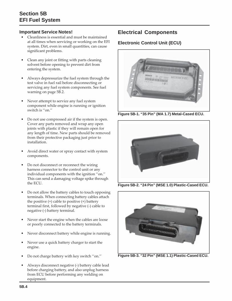
5B.4
Section 5BEFI Fuel System
Important Service Notes!• Cleanliness is essential and must be maintained
at all times when servicing or working on the EFIsystem. Dirt, even in small quantities, can causesignificant problems.
• Clean any joint or fitting with parts cleaningsolvent before opening to prevent dirt fromentering the system.
• Always depressurize the fuel system through thetest valve in fuel rail before disconnecting orservicing any fuel system components. See fuelwarning on page 5B.2.
• Never attempt to service any fuel systemcomponent while engine is running or ignitionswitch is ‘‘on.’’
• Do not use compressed air if the system is open.Cover any parts removed and wrap any openjoints with plastic if they will remain open forany length of time. New parts should be removedfrom their protective packaging just prior toinstallation.
• Avoid direct water or spray contact with systemcomponents.
• Do not disconnect or reconnect the wiringharness connector to the control unit or anyindividual components with the ignition ‘‘on.’’This can send a damaging voltage spike throughthe ECU.
• Do not allow the battery cables to touch opposingterminals. When connecting battery cables attachthe positive (+) cable to positive (+) batteryterminal first, followed by negative (-) cable tonegative (-) battery terminal.
• Never start the engine when the cables are looseor poorly connected to the battery terminals.
• Never disconnect battery while engine is running.
• Never use a quick battery charger to start theengine.
• Do not charge battery with key switch ‘‘on.’’
• Always disconnect negative (-) battery cable leadbefore charging battery, and also unplug harnessfrom ECU before performing any welding onequipment.
Electrical Components
Electronic Control Unit (ECU)
Figure 5B-1. “35 Pin” (MA 1.7) Metal-Cased ECU.
Figure 5B-2. “24 Pin” (MSE 1.0) Plastic-Cased ECU.
Figure 5B-3. “32 Pin” (MSE 1.1) Plastic-Cased ECU.
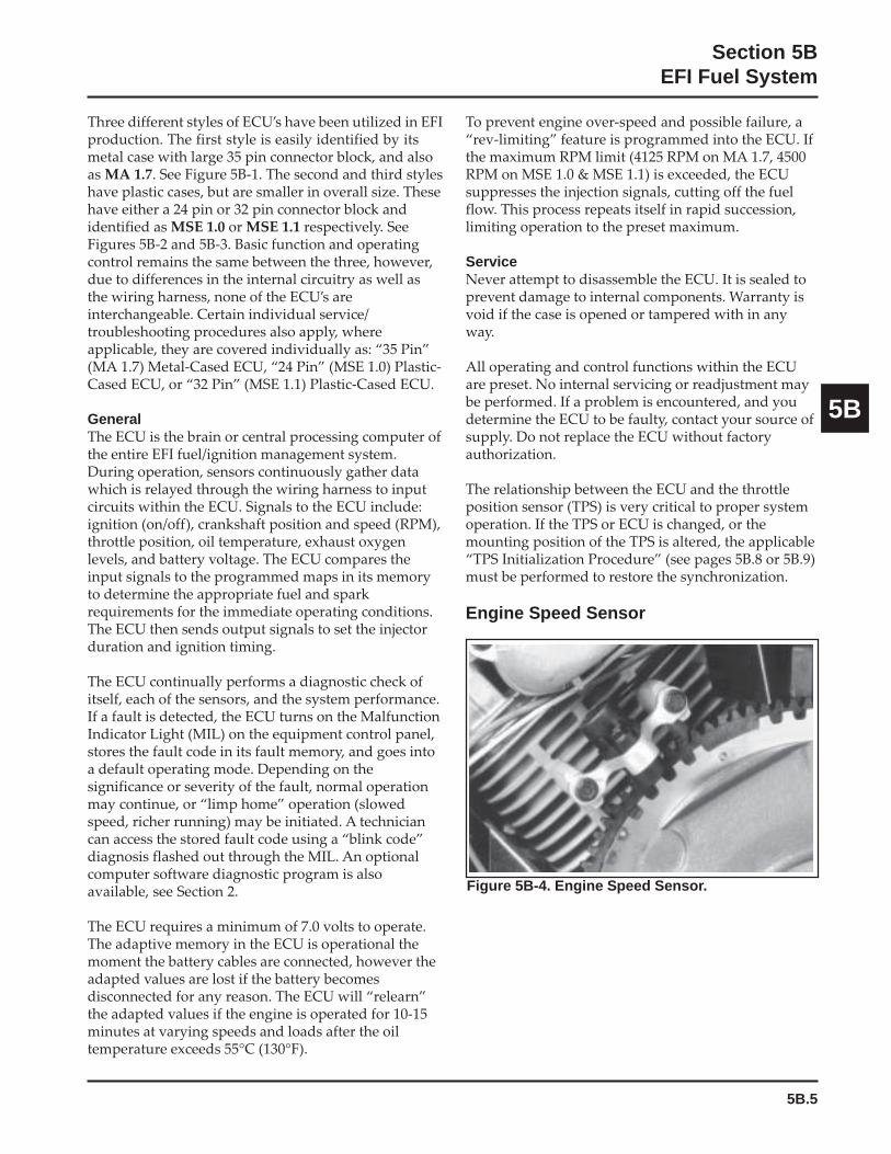
5B.5
Section 5BEFI Fuel System
5B
Three different styles of ECU’s have been utilized in EFIproduction. The first style is easily identified by itsmetal case with large 35 pin connector block, and alsoas MA 1.7. See Figure 5B-1. The second and third styleshave plastic cases, but are smaller in overall size. Thesehave either a 24 pin or 32 pin connector block andidentified as MSE 1.0 or MSE 1.1 respectively. SeeFigures 5B-2 and 5B-3. Basic function and operatingcontrol remains the same between the three, however,due to differences in the internal circuitry as well asthe wiring harness, none of the ECU’s areinterchangeable. Certain individual service/troubleshooting procedures also apply, whereapplicable, they are covered individually as: “35 Pin”(MA 1.7) Metal-Cased ECU, “24 Pin” (MSE 1.0) Plastic-Cased ECU, or “32 Pin” (MSE 1.1) Plastic-Cased ECU.
GeneralThe ECU is the brain or central processing computer ofthe entire EFI fuel/ignition management system.During operation, sensors continuously gather datawhich is relayed through the wiring harness to inputcircuits within the ECU. Signals to the ECU include:ignition (on/off), crankshaft position and speed (RPM),throttle position, oil temperature, exhaust oxygenlevels, and battery voltage. The ECU compares theinput signals to the programmed maps in its memoryto determine the appropriate fuel and sparkrequirements for the immediate operating conditions.The ECU then sends output signals to set the injectorduration and ignition timing.
The ECU continually performs a diagnostic check ofitself, each of the sensors, and the system performance.If a fault is detected, the ECU turns on the MalfunctionIndicator Light (MIL) on the equipment control panel,stores the fault code in its fault memory, and goes intoa default operating mode. Depending on thesignificance or severity of the fault, normal operationmay continue, or “limp home” operation (slowedspeed, richer running) may be initiated. A techniciancan access the stored fault code using a “blink code”diagnosis flashed out through the MIL. An optionalcomputer software diagnostic program is alsoavailable, see Section 2.
The ECU requires a minimum of 7.0 volts to operate.The adaptive memory in the ECU is operational themoment the battery cables are connected, however theadapted values are lost if the battery becomesdisconnected for any reason. The ECU will “relearn”the adapted values if the engine is operated for 10-15minutes at varying speeds and loads after the oiltemperature exceeds 55°C (130°F).
To prevent engine over-speed and possible failure, a“rev-limiting” feature is programmed into the ECU. Ifthe maximum RPM limit (4125 RPM on MA 1.7, 4500RPM on MSE 1.0 & MSE 1.1) is exceeded, the ECUsuppresses the injection signals, cutting off the fuelflow. This process repeats itself in rapid succession,limiting operation to the preset maximum.
ServiceNever attempt to disassemble the ECU. It is sealed toprevent damage to internal components. Warranty isvoid if the case is opened or tampered with in anyway.
All operating and control functions within the ECUare preset. No internal servicing or readjustment maybe performed. If a problem is encountered, and youdetermine the ECU to be faulty, contact your source ofsupply. Do not replace the ECU without factoryauthorization.
The relationship between the ECU and the throttleposition sensor (TPS) is very critical to proper systemoperation. If the TPS or ECU is changed, or themounting position of the TPS is altered, the applicable“TPS Initialization Procedure” (see pages 5B.8 or 5B.9)must be performed to restore the synchronization.
Engine Speed Sensor
Figure 5B-4. Engine Speed Sensor.
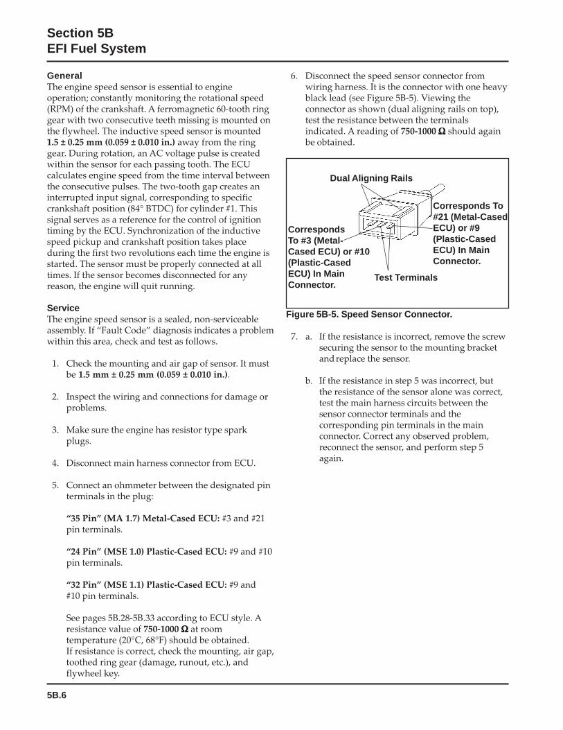
5B.6
Section 5BEFI Fuel System
GeneralThe engine speed sensor is essential to engineoperation; constantly monitoring the rotational speed(RPM) of the crankshaft. A ferromagnetic 60-tooth ringgear with two consecutive teeth missing is mounted onthe flywheel. The inductive speed sensor is mounted1.5 ± 0.25 mm (0.059 ± 0.010 in.) away from the ringgear. During rotation, an AC voltage pulse is createdwithin the sensor for each passing tooth. The ECUcalculates engine speed from the time interval betweenthe consecutive pulses. The two-tooth gap creates aninterrupted input signal, corresponding to specificcrankshaft position (84° BTDC) for cylinder #1. Thissignal serves as a reference for the control of ignitiontiming by the ECU. Synchronization of the inductivespeed pickup and crankshaft position takes placeduring the first two revolutions each time the engine isstarted. The sensor must be properly connected at alltimes. If the sensor becomes disconnected for anyreason, the engine will quit running.
ServiceThe engine speed sensor is a sealed, non-serviceableassembly. If “Fault Code” diagnosis indicates a problemwithin this area, check and test as follows.
1. Check the mounting and air gap of sensor. It mustbe 1.5 mm ± 0.25 mm (0.059 ± 0.010 in.).
2. Inspect the wiring and connections for damage orproblems.
3. Make sure the engine has resistor type sparkplugs.
4. Disconnect main harness connector from ECU.
5. Connect an ohmmeter between the designated pinterminals in the plug:
“35 Pin” (MA 1.7) Metal-Cased ECU: #3 and #21pin terminals.
“24 Pin” (MSE 1.0) Plastic-Cased ECU: #9 and #10pin terminals.
“32 Pin” (MSE 1.1) Plastic-Cased ECU: #9 and#10 pin terminals.
See pages 5B.28-5B.33 according to ECU style. Aresistance value of 750-1000 ΩΩΩΩΩ at roomtemperature (20°C, 68°F) should be obtained.If resistance is correct, check the mounting, air gap,toothed ring gear (damage, runout, etc.), andflywheel key.
6. Disconnect the speed sensor connector fromwiring harness. It is the connector with one heavyblack lead (see Figure 5B-5). Viewing theconnector as shown (dual aligning rails on top),test the resistance between the terminalsindicated. A reading of 750-1000 ΩΩΩΩΩ should againbe obtained.
Dual Aligning Rails
Test Terminals
CorrespondsTo #3 (Metal-Cased ECU) or #10(Plastic-CasedECU) In MainConnector.
Corresponds To#21 (Metal-CasedECU) or #9(Plastic-CasedECU) In MainConnector.
Figure 5B-5. Speed Sensor Connector.
7. a. If the resistance is incorrect, remove the screwsecuring the sensor to the mounting bracketandreplace the sensor.
b. If the resistance in step 5 was incorrect, butthe resistance of the sensor alone was correct,test the main harness circuits between thesensor connector terminals and thecorresponding pin terminals in the mainconnector. Correct any observed problem,reconnect the sensor, and perform step 5again.
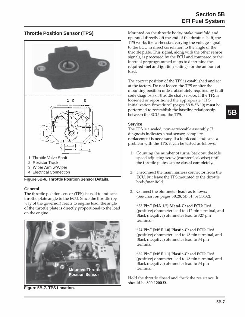
5B.7
Section 5BEFI Fuel System
5B
Mounted on the throttle body/intake manifold andoperated directly off the end of the throttle shaft, theTPS works like a rheostat, varying the voltage signalto the ECU in direct correlation to the angle of thethrottle plate. This signal, along with the other sensorsignals, is processed by the ECU and compared to theinternal preprogrammed maps to determine therequired fuel and ignition settings for the amount ofload.
The correct position of the TPS is established and setat the factory. Do not loosen the TPS or alter themounting position unless absolutely required by faultcode diagnosis or throttle shaft service. If the TPS isloosened or repositioned the appropriate “TPSInitialization Procedure” (pages 5B.8-5B.10) must beperformed to reestablish the baseline relationshipbetween the ECU and the TPS.
ServiceThe TPS is a sealed, non-serviceable assembly. Ifdiagnosis indicates a bad sensor, completereplacement is necessary. If a blink code indicates aproblem with the TPS, it can be tested as follows:
1. Counting the number of turns, back out the idlespeed adjusting screw (counterclockwise) untilthe throttle plates can be closed completely.
2. Disconnect the main harness connector from theECU, but leave the TPS mounted to the throttlebody/manifold.
3. Connect the ohmmeter leads as follows:(See chart on pages 5B.28, 5B.31, or 5B.32).
“35 Pin” (MA 1.7) Metal-Cased ECU: Red(positive) ohmmeter lead to #12 pin terminal, andBlack (negative) ohmmeter lead to #27 pinterminal.
“24 Pin” (MSE 1.0) Plastic-Cased ECU: Red(positive) ohmmeter lead to #8 pin terminal, andBlack (negative) ohmmeter lead to #4 pinterminal.
“32 Pin” (MSE 1.1) Plastic-Cased ECU: Red(positive) ohmmeter lead to #8 pin terminal, andBlack (negative) ohmmeter lead to #4 pinterminal.
Hold the throttle closed and check the resistance. Itshould be 800-1200 ΩΩΩΩΩ.
Figure 5B-6. Throttle Position Sensor Details.
GeneralThe throttle position sensor (TPS) is used to indicatethrottle plate angle to the ECU. Since the throttle (byway of the governor) reacts to engine load, the angleof the throttle plate is directly proportional to the loadon the engine.
1 2 3
4
1. Throttle Valve Shaft2. Resistor Track3. Wiper Arm w/Wiper4. Electrical Connection
Throttle Position Sensor (TPS)
Figure 5B-7. TPS Location.
Mounted ThrottlePosition Sensor
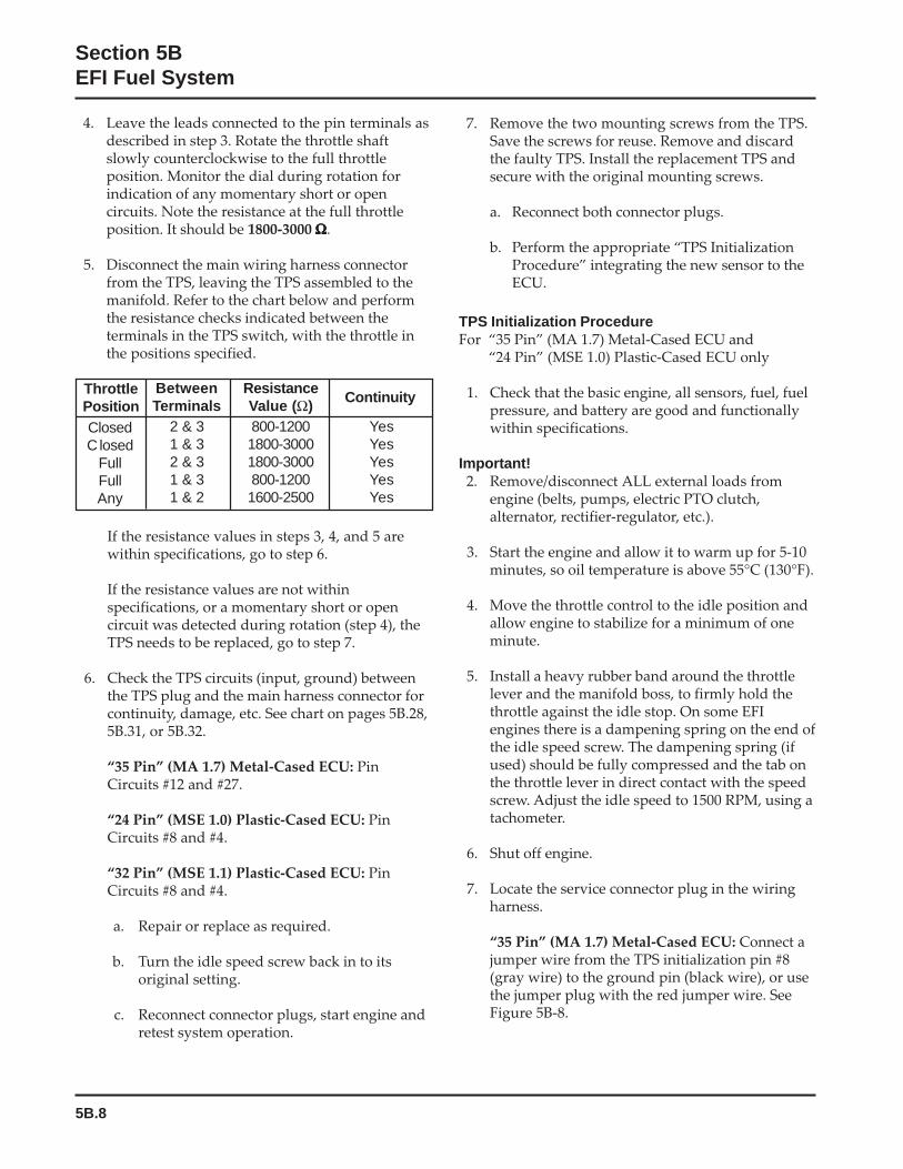
5B.8
Section 5BEFI Fuel System
If the resistance values in steps 3, 4, and 5 arewithin specifications, go to step 6.
If the resistance values are not withinspecifications, or a momentary short or opencircuit was detected during rotation (step 4), theTPS needs to be replaced, go to step 7.
6. Check the TPS circuits (input, ground) betweenthe TPS plug and the main harness connector forcontinuity, damage, etc. See chart on pages 5B.28,5B.31, or 5B.32.
“35 Pin” (MA 1.7) Metal-Cased ECU: PinCircuits #12 and #27.
“24 Pin” (MSE 1.0) Plastic-Cased ECU: PinCircuits #8 and #4.
“32 Pin” (MSE 1.1) Plastic-Cased ECU: PinCircuits #8 and #4.
a. Repair or replace as required.
b. Turn the idle speed screw back in to itsoriginal setting.
c. Reconnect connector plugs, start engine andretest system operation.
7. Remove the two mounting screws from the TPS.Save the screws for reuse. Remove and discardthe faulty TPS. Install the replacement TPS andsecure with the original mounting screws.
a. Reconnect both connector plugs.
b. Perform the appropriate “TPS InitializationProcedure” integrating the new sensor to theECU.
TPS Initialization ProcedureFor “35 Pin” (MA 1.7) Metal-Cased ECU and
“24 Pin” (MSE 1.0) Plastic-Cased ECU only
1. Check that the basic engine, all sensors, fuel, fuelpressure, and battery are good and functionallywithin specifications.
Important!2. Remove/disconnect ALL external loads from
engine (belts, pumps, electric PTO clutch,alternator, rectifier-regulator, etc.).
3. Start the engine and allow it to warm up for 5-10minutes, so oil temperature is above 55°C (130°F).
4. Move the throttle control to the idle position andallow engine to stabilize for a minimum of oneminute.
5. Install a heavy rubber band around the throttlelever and the manifold boss, to firmly hold thethrottle against the idle stop. On some EFIengines there is a dampening spring on the end ofthe idle speed screw. The dampening spring (ifused) should be fully compressed and the tab onthe throttle lever in direct contact with the speedscrew. Adjust the idle speed to 1500 RPM, using atachometer.
6. Shut off engine.
7. Locate the service connector plug in the wiringharness.
“35 Pin” (MA 1.7) Metal-Cased ECU: Connect ajumper wire from the TPS initialization pin #8(gray wire) to the ground pin (black wire), or usethe jumper plug with the red jumper wire. SeeFigure 5B-8.
ThrottlePositionClosedC losed
FullFullAny
BetweenTerminals
2 & 31 & 32 & 31 & 31 & 2
ResistanceValue (Ω)800-12001800-30001800-3000800-12001600-2500
Continuity
YesYesYesYesYes
4. Leave the leads connected to the pin terminals asdescribed in step 3. Rotate the throttle shaftslowly counterclockwise to the full throttleposition. Monitor the dial during rotation forindication of any momentary short or opencircuits. Note the resistance at the full throttleposition. It should be 1800-3000 ΩΩΩΩΩ.
5. Disconnect the main wiring harness connectorfrom the TPS, leaving the TPS assembled to themanifold. Refer to the chart below and performthe resistance checks indicated between theterminals in the TPS switch, with the throttle inthe positions specified.
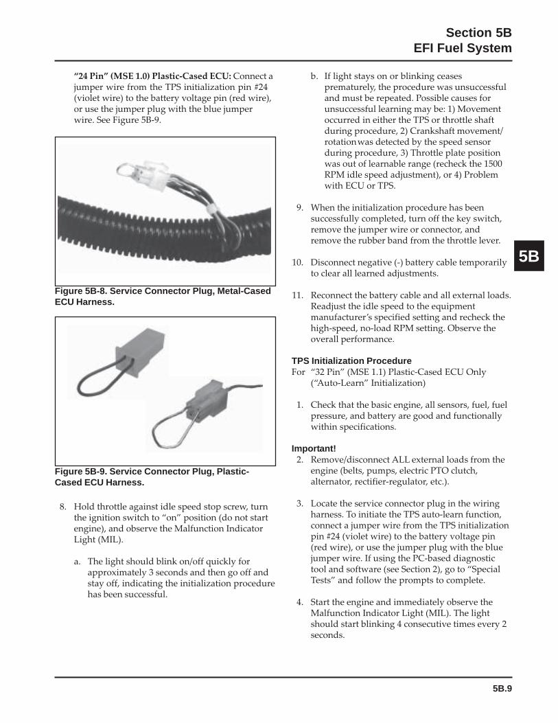
5B.9
Section 5BEFI Fuel System
5B
b. If light stays on or blinking ceasesprematurely, the procedure was unsuccessfuland must be repeated. Possible causes forunsuccessful learning may be: 1) Movementoccurred in either the TPS or throttle shaftduring procedure, 2) Crankshaft movement/rotationwas detected by the speed sensorduring procedure, 3) Throttle plate positionwas out of learnable range (recheck the 1500RPM idle speed adjustment), or 4) Problemwith ECU or TPS.
9. When the initialization procedure has beensuccessfully completed, turn off the key switch,remove the jumper wire or connector, andremove the rubber band from the throttle lever.
10. Disconnect negative (-) battery cable temporarilyto clear all learned adjustments.
11. Reconnect the battery cable and all external loads.Readjust the idle speed to the equipmentmanufacturer’s specified setting and recheck thehigh-speed, no-load RPM setting. Observe theoverall performance.
TPS Initialization ProcedureFor “32 Pin” (MSE 1.1) Plastic-Cased ECU Only
(“Auto-Learn” Initialization)
1. Check that the basic engine, all sensors, fuel, fuelpressure, and battery are good and functionallywithin specifications.
Important!2. Remove/disconnect ALL external loads from the
engine (belts, pumps, electric PTO clutch,alternator, rectifier-regulator, etc.).
3. Locate the service connector plug in the wiringharness. To initiate the TPS auto-learn function,connect a jumper wire from the TPS initializationpin #24 (violet wire) to the battery voltage pin(red wire), or use the jumper plug with the bluejumper wire. If using the PC-based diagnostictool and software (see Section 2), go to “SpecialTests” and follow the prompts to complete.
4. Start the engine and immediately observe theMalfunction Indicator Light (MIL). The lightshould start blinking 4 consecutive times every 2seconds.
“24 Pin” (MSE 1.0) Plastic-Cased ECU: Connect ajumper wire from the TPS initialization pin #24(violet wire) to the battery voltage pin (red wire),or use the jumper plug with the blue jumperwire. See Figure 5B-9.
Figure 5B-8. Service Connector Plug, Metal-CasedECU Harness.
Figure 5B-9. Service Connector Plug, Plastic-Cased ECU Harness.
8. Hold throttle against idle speed stop screw, turnthe ignition switch to “on” position (do not startengine), and observe the Malfunction IndicatorLight (MIL).
a. The light should blink on/off quickly forapproximately 3 seconds and then go off andstay off, indicating the initialization procedurehas been successful.
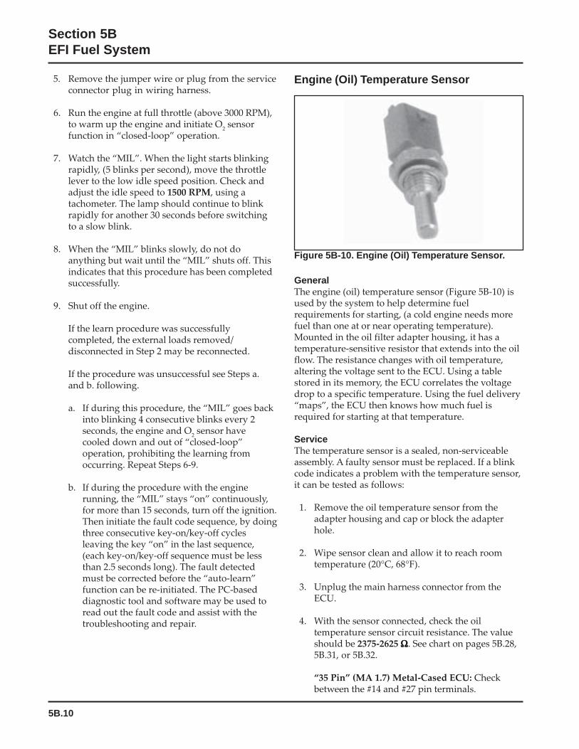
5B.10
Section 5BEFI Fuel System
Figure 5B-10. Engine (Oil) Temperature Sensor.
GeneralThe engine (oil) temperature sensor (Figure 5B-10) isused by the system to help determine fuelrequirements for starting, (a cold engine needs morefuel than one at or near operating temperature).Mounted in the oil filter adapter housing, it has atemperature-sensitive resistor that extends into the oilflow. The resistance changes with oil temperature,altering the voltage sent to the ECU. Using a tablestored in its memory, the ECU correlates the voltagedrop to a specific temperature. Using the fuel delivery“maps”, the ECU then knows how much fuel isrequired for starting at that temperature.
ServiceThe temperature sensor is a sealed, non-serviceableassembly. A faulty sensor must be replaced. If a blinkcode indicates a problem with the temperature sensor,it can be tested as follows:
1. Remove the oil temperature sensor from theadapter housing and cap or block the adapterhole.
2. Wipe sensor clean and allow it to reach roomtemperature (20°C, 68°F).
3. Unplug the main harness connector from theECU.
4. With the sensor connected, check the oiltemperature sensor circuit resistance. The valueshould be 2375-2625 ΩΩΩΩΩ. See chart on pages 5B.28,5B.31, or 5B.32.
“35 Pin” (MA 1.7) Metal-Cased ECU: Checkbetween the #14 and #27 pin terminals.
5. Remove the jumper wire or plug from the serviceconnector plug in wiring harness.
6. Run the engine at full throttle (above 3000 RPM),to warm up the engine and initiate O
2 sensor
function in “closed-loop” operation.
7. Watch the “MIL”. When the light starts blinkingrapidly, (5 blinks per second), move the throttlelever to the low idle speed position. Check andadjust the idle speed to 1500 RPM, using atachometer. The lamp should continue to blinkrapidly for another 30 seconds before switchingto a slow blink.
8. When the “MIL” blinks slowly, do not doanything but wait until the “MIL” shuts off. Thisindicates that this procedure has been completedsuccessfully.
9. Shut off the engine.
If the learn procedure was successfullycompleted, the external loads removed/disconnected in Step 2 may be reconnected.
If the procedure was unsuccessful see Steps a.and b. following.
a. If during this procedure, the “MIL” goes backinto blinking 4 consecutive blinks every 2seconds, the engine and O
2 sensor have
cooled down and out of “closed-loop”operation, prohibiting the learning fromoccurring. Repeat Steps 6-9.
b. If during the procedure with the enginerunning, the “MIL” stays “on” continuously,for more than 15 seconds, turn off the ignition.Then initiate the fault code sequence, by doingthree consecutive key-on/key-off cyclesleaving the key “on” in the last sequence,(each key-on/key-off sequence must be lessthan 2.5 seconds long). The fault detectedmust be corrected before the “auto-learn”function can be re-initiated. The PC-baseddiagnostic tool and software may be used toread out the fault code and assist with thetroubleshooting and repair.
Engine (Oil) Temperature Sensor
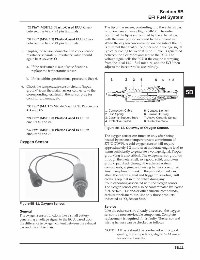
5B.11
Section 5BEFI Fuel System
5B
Figure 5B-12. Cutaway of Oxygen Sensor.
The oxygen sensor can function only after beingheated by exhaust temperatures to a minimum of375°C (709°F). A cold oxygen sensor will requireapproximately 1-2 minutes at moderate engine load towarm sufficiently to generate a voltage signal. Propergrounding is also critical. The oxygen sensor groundsthrough the metal shell, so a good, solid, unbrokenground path back through the exhaust systemcomponents, engine, and wiring harness is required.Any disruption or break in the ground circuit canaffect the output signal and trigger misleading faultcodes. Keep that in mind when doing anytroubleshooting associated with the oxygen sensor.The oxygen sensor can also be contaminated by leadedfuel, certain RTV and/or other silicone compounds,carburetor cleaners, etc. Use only those productsindicated as “O
² Sensor Safe.”
ServiceLike the other sensors already discussed, the oxygensensor is a non-serviceable component. Completereplacement is required if it is faulty. The sensor andwiring harness can be checked as follows.
NOTE: All tests should be conducted with a goodquality, high-impedance, digital VOA meterfor accurate results.
“24 Pin” (MSE 1.0) Plastic-Cased ECU: Checkbetween the #6 and #4 pin terminals.
“32 Pin” (MSE 1.1) Plastic-Cased ECU: Checkbetween the #6 and #4 pin terminals.
5. Unplug the sensor connector and check sensorresistance separately. Resistance value shouldagain be 2375-2625 ΩΩΩΩΩ.
a. If the resistance is out of specifications,replace the temperature sensor.
b. If it is within specifications, proceed to Step 6.
6. Check the temperature sensor circuits (input,ground) from the main harness connector to thecorresponding terminal in the sensor plug forcontinuity, damage, etc.
“35 Pin” (MA 1.7) Metal-Cased ECU: Pin circuits#14 and #27.
“24 Pin” (MSE 1.0) Plastic-Cased ECU: Pincircuits #6 and #4.
“32 Pin” (MSE 1.1) Plastic-Cased ECU: Pincircuits #6 and #4.
Oxygen Sensor
Figure 5B-11. Oxygen Sensor.
GeneralThe oxygen sensor functions like a small battery,generating a voltage signal to the ECU, based uponthe difference in oxygen content between the exhaustgas and the ambient air.
The tip of the sensor, protruding into the exhaust gas,is hollow (see cutaway Figure 5B-12). The outerportion of the tip is surrounded by the exhaust gas,with the inner portion exposed to the ambient air.When the oxygen concentration on one side of the tipis different than that of the other side, a voltage signaltypically cycling between 0.2 and 1.0 volt is generatedbetween the electrodes and sent to the ECU. Thevoltage signal tells the ECU if the engine is strayingfrom the ideal 14.7:1 fuel mixture, and the ECU thenadjusts the injector pulse accordingly.
1 2 3 4 5 6 7 8
1. Connection Cable2. Disc Spring3. Ceramic Support Tube4. Protective Sleeve
5. Contact Element6. Sensor Housing7. Active Ceramic Sensor8. Protective Tube
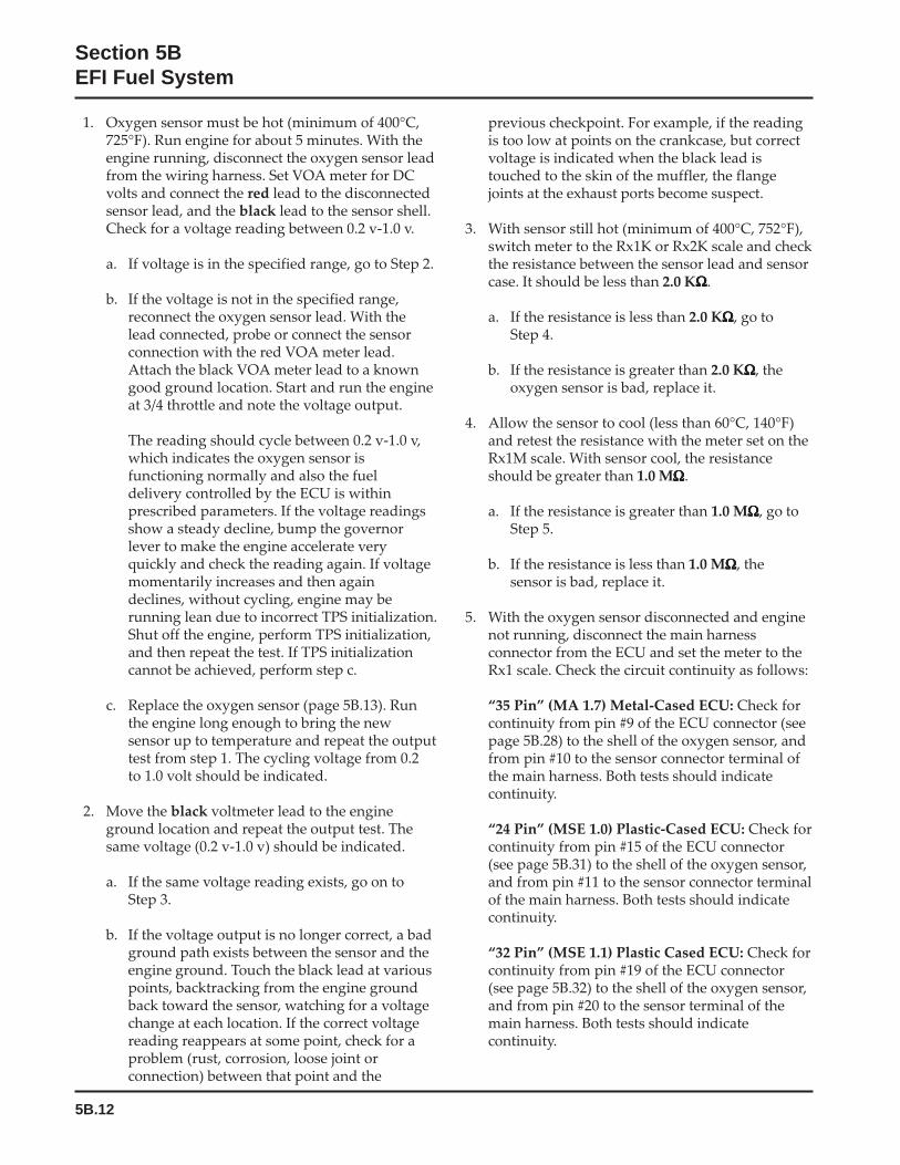
5B.12
Section 5BEFI Fuel System
1. Oxygen sensor must be hot (minimum of 400°C,725°F). Run engine for about 5 minutes. With theengine running, disconnect the oxygen sensor leadfrom the wiring harness. Set VOA meter for DCvolts and connect the red lead to the disconnectedsensor lead, and the black lead to the sensor shell.Check for a voltage reading between 0.2 v-1.0 v.
a. If voltage is in the specified range, go to Step 2.
b. If the voltage is not in the specified range,reconnect the oxygen sensor lead. With thelead connected, probe or connect the sensorconnection with the red VOA meter lead.Attach the black VOA meter lead to a knowngood ground location. Start and run the engineat 3/4 throttle and note the voltage output.
The reading should cycle between 0.2 v-1.0 v,which indicates the oxygen sensor isfunctioning normally and also the fueldelivery controlled by the ECU is withinprescribed parameters. If the voltage readingsshow a steady decline, bump the governorlever to make the engine accelerate veryquickly and check the reading again. If voltagemomentarily increases and then againdeclines, without cycling, engine may berunning lean due to incorrect TPS initialization.Shut off the engine, perform TPS initialization,and then repeat the test. If TPS initializationcannot be achieved, perform step c.
c. Replace the oxygen sensor (page 5B.13). Runthe engine long enough to bring the newsensor up to temperature and repeat the outputtest from step 1. The cycling voltage from 0.2to 1.0 volt should be indicated.
2. Move the black voltmeter lead to the engineground location and repeat the output test. Thesame voltage (0.2 v-1.0 v) should be indicated.
a. If the same voltage reading exists, go on toStep 3.
b. If the voltage output is no longer correct, a badground path exists between the sensor and theengine ground. Touch the black lead at variouspoints, backtracking from the engine groundback toward the sensor, watching for a voltagechange at each location. If the correct voltagereading reappears at some point, check for aproblem (rust, corrosion, loose joint orconnection) between that point and the
previous checkpoint. For example, if the readingis too low at points on the crankcase, but correctvoltage is indicated when the black lead istouched to the skin of the muffler, the flangejoints at the exhaust ports become suspect.
3. With sensor still hot (minimum of 400°C, 752°F),switch meter to the Rx1K or Rx2K scale and checkthe resistance between the sensor lead and sensorcase. It should be less than 2.0 KΩΩΩΩΩ.
a. If the resistance is less than 2.0 KΩΩΩΩΩ, go toStep 4.
b. If the resistance is greater than 2.0 KΩΩΩΩΩ, theoxygen sensor is bad, replace it.
4. Allow the sensor to cool (less than 60°C, 140°F)and retest the resistance with the meter set on theRx1M scale. With sensor cool, the resistanceshould be greater than 1.0 MΩΩΩΩΩ.
a. If the resistance is greater than 1.0 MΩΩΩΩΩ, go toStep 5.
b. If the resistance is less than 1.0 MΩΩΩΩΩ, thesensor is bad, replace it.
5. With the oxygen sensor disconnected and enginenot running, disconnect the main harnessconnector from the ECU and set the meter to theRx1 scale. Check the circuit continuity as follows:
“35 Pin” (MA 1.7) Metal-Cased ECU: Check forcontinuity from pin #9 of the ECU connector (seepage 5B.28) to the shell of the oxygen sensor, andfrom pin #10 to the sensor connector terminal ofthe main harness. Both tests should indicatecontinuity.
“24 Pin” (MSE 1.0) Plastic-Cased ECU: Check forcontinuity from pin #15 of the ECU connector(see page 5B.31) to the shell of the oxygen sensor,and from pin #11 to the sensor connector terminalof the main harness. Both tests should indicatecontinuity.
“32 Pin” (MSE 1.1) Plastic Cased ECU: Check forcontinuity from pin #19 of the ECU connector(see page 5B.32) to the shell of the oxygen sensor,and from pin #20 to the sensor terminal of themain harness. Both tests should indicatecontinuity.

5B.13
Section 5BEFI Fuel System
5B
a. If there is no continuity displayed in either ofthe tests, check the harness circuit for breaksor damage, and the connections for poorcontact, moisture, or corrosion. If nocontinuity was found in the first test, alsocheck for a poor/broken ground path backthrough the exhaust system, engine, andmounting (sensor is grounded through itsshell).
b. If continuity is indicated, go to step 6.
6. With the key switch in the ‘‘on/run’’ position,using a high impedance voltmeter, check thevoltage from the wiring harness oxygen sensorconnector to the engine ground location. Look fora steady voltage from 350-550 mv (0.35-0.55 v).
a. If voltage reading is not as specified, move theblack voltmeter lead to the negative post ofthe battery, to be certain of a good ground. Ifthe voltage is still not correct, the ECU isprobably bad.
b. If voltage readings are correct, clear the faultcodes and run the engine to check if any faultcodes reappear.
To Replace Oxygen Sensor1. Disconnect the oxygen sensor connector from
wiring harness.
2. Loosen and remove the oxygen sensor from theexhaust manifold/muffler assembly.
3. Apply anti-seize compound sparingly to threadsof new oxygen sensor, if none already exists. DONOT get any on the tip as it will contaminate thesensor. Install sensor and torque to 50-60 N·m(37-44 ft. lb.).
4. Reconnect the lead to wiring harness connector.Make sure it can not contact hot surfaces, movingparts, etc.
5. Test run the engine.
Electrical Relay
Figure 5B-13. Electrical Relay.
GeneralThe electrical relay is used to supply power to theinjectors, coils, and fuel pump. When the key switch isturned “on” and all safety switch requirements met,the relay provides 12 volts to the fuel pump circuit,injectors, and ignition coils. The fuel pump circuit iscontinuously grounded, so the pump is immediatelyactivated and pressurizes the system. Activation of theignition coils and injectors is controlled by the ECU,which grounds their respective circuits at the propertimes.
ServiceA malfunctioning relay can result in starting oroperating difficulties. The relay and related wiring canbe tested as follows:
1. Disconnect the relay connector plug from therelay.
2. Connect black lead of VOA meter to a chassisground location. Connect red lead to the #86terminal in relay connector (see Figure 5B-14). Setmeter to test resistance (Rx1). Turn ignitionswitch from “off” to “on”. Meter should indicatecontinuity (ground circuit is completed) for 1 to 3seconds. Turn key switch back off.
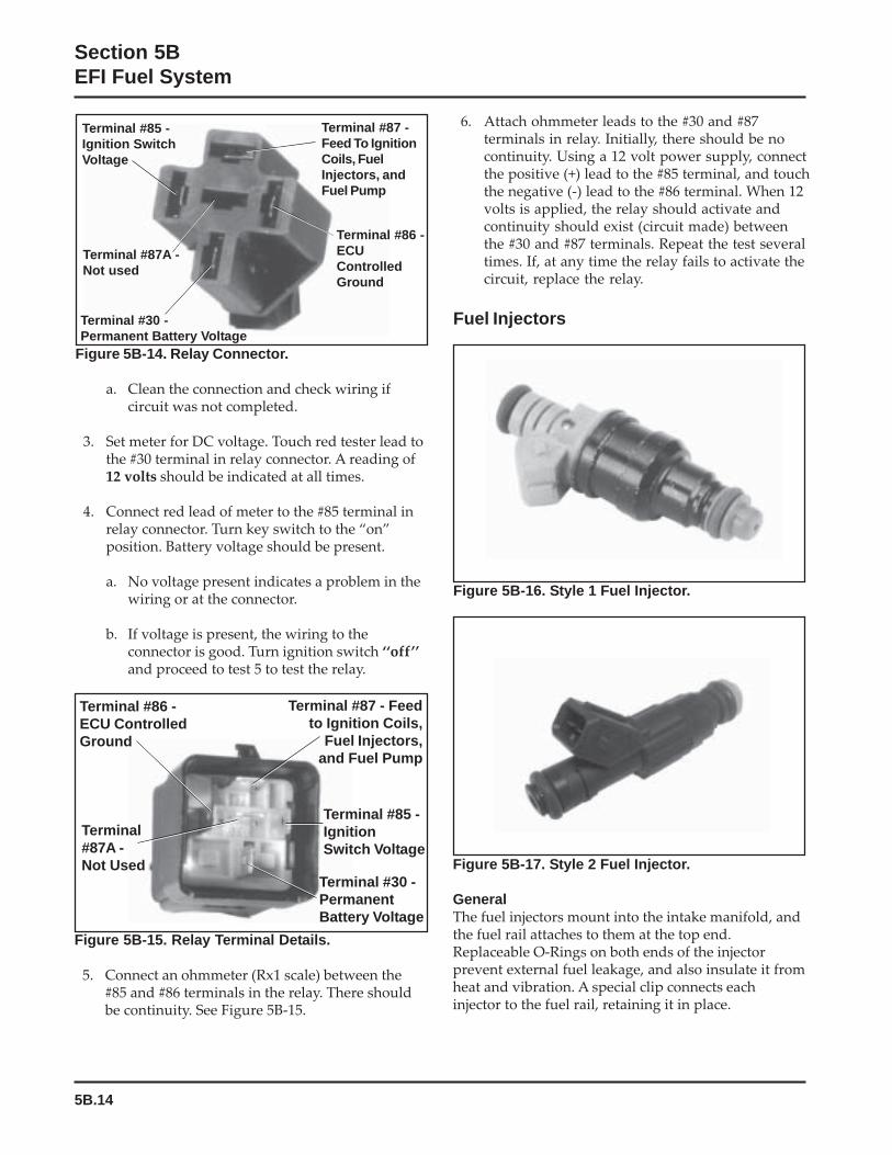
5B.14
Section 5BEFI Fuel System
Figure 5B-17. Style 2 Fuel Injector.
GeneralThe fuel injectors mount into the intake manifold, andthe fuel rail attaches to them at the top end.Replaceable O-Rings on both ends of the injectorprevent external fuel leakage, and also insulate it fromheat and vibration. A special clip connects eachinjector to the fuel rail, retaining it in place.
Figure 5B-15. Relay Terminal Details.
5. Connect an ohmmeter (Rx1 scale) between the#85 and #86 terminals in the relay. There shouldbe continuity. See Figure 5B-15.
Figure 5B-14. Relay Connector.
a. Clean the connection and check wiring ifcircuit was not completed.
3. Set meter for DC voltage. Touch red tester lead tothe #30 terminal in relay connector. A reading of12 volts should be indicated at all times.
4. Connect red lead of meter to the #85 terminal inrelay connector. Turn key switch to the “on”position. Battery voltage should be present.
a. No voltage present indicates a problem in thewiring or at the connector.
b. If voltage is present, the wiring to theconnector is good. Turn ignition switch ‘‘off’’and proceed to test 5 to test the relay.
6. Attach ohmmeter leads to the #30 and #87terminals in relay. Initially, there should be nocontinuity. Using a 12 volt power supply, connectthe positive (+) lead to the #85 terminal, and touchthe negative (-) lead to the #86 terminal. When 12volts is applied, the relay should activate andcontinuity should exist (circuit made) betweenthe #30 and #87 terminals. Repeat the test severaltimes. If, at any time the relay fails to activate thecircuit, replace the relay.
Fuel Injectors
Terminal #87 -Feed To IgnitionCoils, FuelInjectors, andFuel Pump
Terminal #86 -ECUControlledGround
Terminal #87A -Not used
Terminal #85 -Ignition SwitchVoltage
Terminal #30 -Permanent Battery Voltage
Terminal #85 -IgnitionSwitch Voltage
Terminal #87 - Feedto Ignition Coils,
Fuel Injectors,and Fuel Pump
Terminal #86 -ECU ControlledGround
Terminal #30 -PermanentBattery Voltage
Terminal#87A -Not Used
Figure 5B-16. Style 1 Fuel Injector.
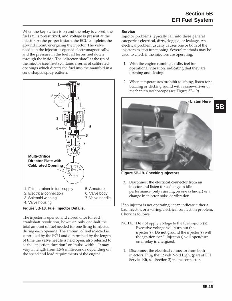
5B.15
Section 5BEFI Fuel System
5B
When the key switch is on and the relay is closed, thefuel rail is pressurized, and voltage is present at theinjector. At the proper instant, the ECU completes theground circuit, energizing the injector. The valveneedle in the injector is opened electromagnetically,and the pressure in the fuel rail forces fuel downthrough the inside. The “director plate” at the tip ofthe injector (see inset) contains a series of calibratedopenings which directs the fuel into the manifold in acone-shaped spray pattern.
ServiceInjector problems typically fall into three generalcategories: electrical, dirty/clogged, or leakage. Anelectrical problem usually causes one or both of theinjectors to stop functioning. Several methods may beused to check if the injectors are operating.
1. With the engine running at idle, feel foroperational vibration, indicating that they areopening and closing.
2. When temperatures prohibit touching, listen for abuzzing or clicking sound with a screwdriver ormechanic’s stethoscope (see Figure 5B-19).
Figure 5B-18. Fuel Injector Details.
The injector is opened and closed once for eachcrankshaft revolution, however, only one-half thetotal amount of fuel needed for one firing is injectedduring each opening. The amount of fuel injected iscontrolled by the ECU and determined by the lengthof time the valve needle is held open, also referred toas the “injection duration” or “pulse width”. It mayvary in length from 1.5-8 milliseconds depending onthe speed and load requirements of the engine.
Figure 5B-19. Checking Injectors.
3. Disconnect the electrical connector from aninjector and listen for a change in idleperformance (only running on one cylinder) or achange in injector noise or vibration.
If an injector is not operating, it can indicate either abad injector, or a wiring/electrical connection problem.Check as follows:
NOTE: Do not apply voltage to the fuel injector(s).Excessive voltage will burn out theinjector(s). Do not ground the injector(s) withthe ignition “on”. Injector(s) will open/turnon if relay is energized.
1. Disconnect the electrical connector from bothinjectors. Plug the 12 volt Noid Light (part of EFIService Kit, see Section 2) in one connector.
1. Filter strainer in fuel supply2. Electrical connection3. Solenoid winding4. Valve housing
Multi-OrificeDirector Plate withCalibrated Opening
5. Armature6. Valve body7. Valve needle
Listen Here
1
2
3
4 5
6
7
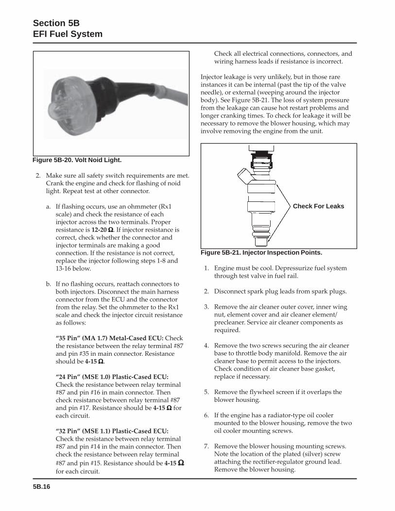
5B.16
Section 5BEFI Fuel System
Figure 5B-21. Injector Inspection Points.
1. Engine must be cool. Depressurize fuel systemthrough test valve in fuel rail.
2. Disconnect spark plug leads from spark plugs.
3. Remove the air cleaner outer cover, inner wingnut, element cover and air cleaner element/precleaner. Service air cleaner components asrequired.
4. Remove the two screws securing the air cleanerbase to throttle body manifold. Remove the aircleaner base to permit access to the injectors.Check condition of air cleaner base gasket,replace if necessary.
5. Remove the flywheel screen if it overlaps theblower housing.
6. If the engine has a radiator-type oil coolermounted to the blower housing, remove the twooil cooler mounting screws.
7. Remove the blower housing mounting screws.Note the location of the plated (silver) screwattaching the rectifier-regulator ground lead.Remove the blower housing.
Figure 5B-20. Volt Noid Light.
2. Make sure all safety switch requirements are met.Crank the engine and check for flashing of noidlight. Repeat test at other connector.
a. If flashing occurs, use an ohmmeter (Rx1scale) and check the resistance of eachinjector across the two terminals. Properresistance is 12-20 ΩΩΩΩΩ. If injector resistance iscorrect, check whether the connector andinjector terminals are making a goodconnection. If the resistance is not correct,replace the injector following steps 1-8 and13-16 below.
b. If no flashing occurs, reattach connectors toboth injectors. Disconnect the main harnessconnector from the ECU and the connectorfrom the relay. Set the ohmmeter to the Rx1scale and check the injector circuit resistanceas follows:
“35 Pin” (MA 1.7) Metal-Cased ECU: Checkthe resistance between the relay terminal #87and pin #35 in main connector. Resistanceshould be 4-15 ΩΩΩΩΩ.
“24 Pin” (MSE 1.0) Plastic-Cased ECU:Check the resistance between relay terminal#87 and pin #16 in main connector. Thencheck resistance between relay terminal #87and pin #17. Resistance should be 4-15 ΩΩΩΩΩ foreach circuit.
“32 Pin” (MSE 1.1) Plastic-Cased ECU:Check the resistance between relay terminal#87 and pin #14 in the main connector. Thencheck the resistance between relay terminal
#87 and pin #15. Resistance should be 4-15 ΩΩΩΩΩfor each circuit.
Check all electrical connections, connectors, andwiring harness leads if resistance is incorrect.
Injector leakage is very unlikely, but in those rareinstances it can be internal (past the tip of the valveneedle), or external (weeping around the injectorbody). See Figure 5B-21. The loss of system pressurefrom the leakage can cause hot restart problems andlonger cranking times. To check for leakage it will benecessary to remove the blower housing, which mayinvolve removing the engine from the unit.
Check For Leaks
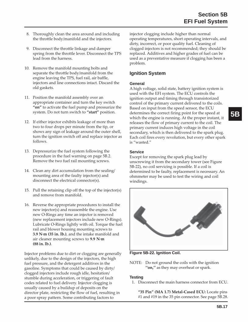
5B.17
Section 5BEFI Fuel System
5B
8. Thoroughly clean the area around and includingthe throttle body/manifold and the injectors.
9. Disconnect the throttle linkage and damperspring from the throttle lever. Disconnect the TPSlead from the harness.
10. Remove the manifold mounting bolts andseparate the throttle body/manifold from theengine leaving the TPS, fuel rail, air baffle,injectors and line connections intact. Discard theold gaskets.
11. Position the manifold assembly over anappropriate container and turn the key switch“on” to activate the fuel pump and pressurize thesystem. Do not turn switch to “start” position.
12. If either injector exhibits leakage of more thantwo to four drops per minute from the tip, orshows any sign of leakage around the outer shell,turn the ignition switch off and replace injector asfollows.
13. Depressurize the fuel system following theprocedure in the fuel warning on page 5B.2.Remove the two fuel rail mounting screws.
14. Clean any dirt accumulation from the sealing/mounting area of the faulty injector(s) anddisconnect the electrical connector(s).
15. Pull the retaining clip off the top of the injector(s)and remove from manifold.
16. Reverse the appropriate procedures to install thenew injector(s) and reassemble the engine. Usenew O-Rings any time an injector is removed(new replacement injectors include new O-Rings).Lubricate O-Rings lightly with oil. Torque the fuelrail and blower housing mounting screws to3.9 N·m (35 in. lb.), and the intake manifold andair cleaner mounting screws to 9.9 N·m(88 in. lb.).
Injector problems due to dirt or clogging are generallyunlikely, due to the design of the injectors, the highfuel pressure, and the detergent additives in thegasoline. Symptoms that could be caused by dirty/clogged injectors include rough idle, hesitation/stumble during acceleration, or triggering of faultcodes related to fuel delivery. Injector clogging isusually caused by a buildup of deposits on thedirector plate, restricting the flow of fuel, resulting ina poor spray pattern. Some contributing factors to
injector clogging include higher than normaloperating temperatures, short operating intervals, anddirty, incorrect, or poor quality fuel. Cleaning ofclogged injectors is not recommended; they should bereplaced. Additives and higher grades of fuel can beused as a preventative measure if clogging has been aproblem.
Ignition System
GeneralA high voltage, solid state, battery ignition system isused with the EFI system. The ECU controls theignition output and timing through transistorizedcontrol of the primary current delivered to the coils.Based on input from the speed sensor, the ECUdetermines the correct firing point for the speed atwhich the engine is running. At the proper instant, itreleases the flow of primary current to the coil. Theprimary current induces high voltage in the coilsecondary, which is then delivered to the spark plug.Each coil fires every revolution, but every other sparkis “wasted.”
ServiceExcept for removing the spark plug lead byunscrewing it from the secondary tower (see Figure5B-22), no coil servicing is possible. If a coil isdetermined to be faulty, replacement is necessary. Anohmmeter may be used to test the wiring and coilwindings.
Figure 5B-22. Ignition Coil.
NOTE: Do not ground the coils with the ignition‘‘on,’’ as they may overheat or spark.
Testing1. Disconnect the main harness connector from ECU.
“35 Pin” (MA 1.7) Metal-Cased ECU: Locate pins#1 and #19 in the 35 pin connector. See page 5B.28.

5B.18
Section 5BEFI Fuel System
4. If the secondary resistance is not withinthe specified range, unscrew the sparkplug lead nut from the coil secondarytower and remove the plug lead. Repeatstep b. 3, testing from the secondarytower terminal to the red primaryterminal. If resistance is now correct, thecoil is good, but the spark plug lead isfaulty, replace the lead. If step b. 2resistance was incorrect and/or thesecondary resistance is still incorrect, thecoil is faulty and needs to be replaced.
Spark PlugsEFI engines are equipped with Champion® RC12YC(Kohler Part No. 12 132 02-S) resistor style sparkplugs. Equivalent alternate brand plugs can also beused, but must be a resistor style plug or permanentdamage to the ECU will occur in addition to affectingoperation. Proper spark plug gap is 0.76 mm(0.030 in.).
Wiring HarnessThe wiring harness used in the EFI system connectsthe electrical components, providing current andground paths for the system to operate. All input andoutput signaling occurs through a special all weatherconnector that attaches and locks to the ECU (seeFigures 5B-23, 5B-24, and 5B-25).
“24 Pin” (MSE 1.0) Plastic-Cased ECU: Locatepins #22 and #23 in the 24 pin connector. See page5B.31.
“32 Pin” (MSE 1.1) Plastic Cased ECU: Locatepins #30 and #31 in the 32 pin connector. See page5B.32.
2. Disconnect connector from relay and locateterminal #87 in connector.
3. Using an ohmmeter set on the Rx1 scale, checkthe resistance in circuits as follows:
“35 Pin” (MA 1.7) Metal-Cased ECU: Checkbetween terminal #87 and pin #1 for coil #1.Repeat the test between terminal #87 and pin #19for coil #2.
“24 Pin” (MSE 1.0) Plastic-Cased ECU: Checkbetween terminal #87 and pin #22 for coil #1.Repeat the test between terminal #87 and pin #23for coil #2.
“32 Pin” (MSE 1.1) Plastic-Cased ECU: Checkbetween terminal #87 and pin #30 for coil #1.Repeat the test between terminal #87 and pin #31for coil #2.
A reading of 1.8-4.0 ΩΩΩΩΩ in each test indicates thatthe wiring and coil primary circuits are OK.
a. If reading(s) are not within specified range,check and clean connections and retest.
b. If reading(s) are still not within the specifiedrange, test the coils separately from mainharness as follows:
1. Disconnect the red and black primaryleads from the coil terminals.
2. Connect an ohmmeter set on the Rx1scale to the primary terminals. Primaryresistance should be 1.8-2.5 ΩΩΩΩΩ.
3. Disconnect the secondary lead from thespark plug. Connect an ohmmeter set onthe Rx10K scale between the spark plugboot terminal and the red primaryterminal. Secondary resistance should be13,000-17,500 ΩΩΩΩΩ.
Figure 5B-23. “35 Pin” (MA 1.7) Metal-Cased ECUConnector and O-Ring.
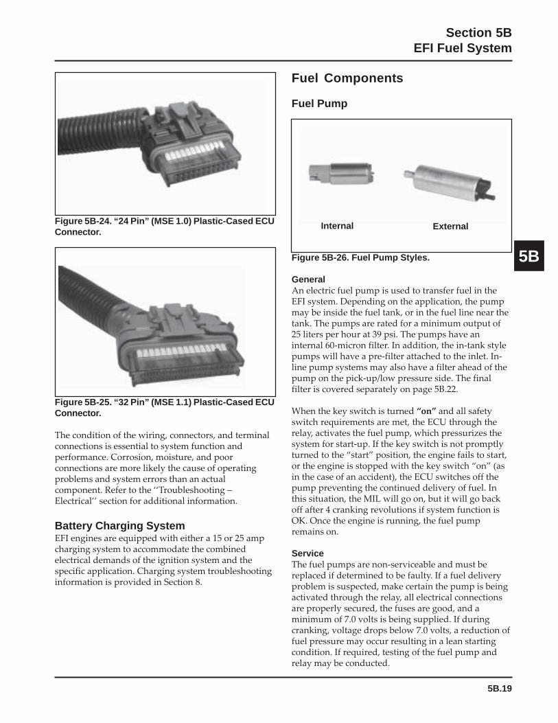
5B.19
Section 5BEFI Fuel System
5B
Figure 5B-24. “24 Pin” (MSE 1.0) Plastic-Cased ECUConnector.
Fuel Components
Fuel Pump
Figure 5B-25. “32 Pin” (MSE 1.1) Plastic-Cased ECUConnector.
The condition of the wiring, connectors, and terminalconnections is essential to system function andperformance. Corrosion, moisture, and poorconnections are more likely the cause of operatingproblems and system errors than an actualcomponent. Refer to the ‘‘Troubleshooting –Electrical’’ section for additional information.
Battery Charging SystemEFI engines are equipped with either a 15 or 25 ampcharging system to accommodate the combinedelectrical demands of the ignition system and thespecific application. Charging system troubleshootinginformation is provided in Section 8.
Figure 5B-26. Fuel Pump Styles.
GeneralAn electric fuel pump is used to transfer fuel in theEFI system. Depending on the application, the pumpmay be inside the fuel tank, or in the fuel line near thetank. The pumps are rated for a minimum output of25 liters per hour at 39 psi. The pumps have aninternal 60-micron filter. In addition, the in-tank stylepumps will have a pre-filter attached to the inlet. In-line pump systems may also have a filter ahead of thepump on the pick-up/low pressure side. The finalfilter is covered separately on page 5B.22.
When the key switch is turned “on” and all safetyswitch requirements are met, the ECU through therelay, activates the fuel pump, which pressurizes thesystem for start-up. If the key switch is not promptlyturned to the “start” position, the engine fails to start,or the engine is stopped with the key switch “on” (asin the case of an accident), the ECU switches off thepump preventing the continued delivery of fuel. Inthis situation, the MIL will go on, but it will go backoff after 4 cranking revolutions if system function isOK. Once the engine is running, the fuel pumpremains on.
ServiceThe fuel pumps are non-serviceable and must bereplaced if determined to be faulty. If a fuel deliveryproblem is suspected, make certain the pump is beingactivated through the relay, all electrical connectionsare properly secured, the fuses are good, and aminimum of 7.0 volts is being supplied. If duringcranking, voltage drops below 7.0 volts, a reduction offuel pressure may occur resulting in a lean startingcondition. If required, testing of the fuel pump andrelay may be conducted.
Internal External
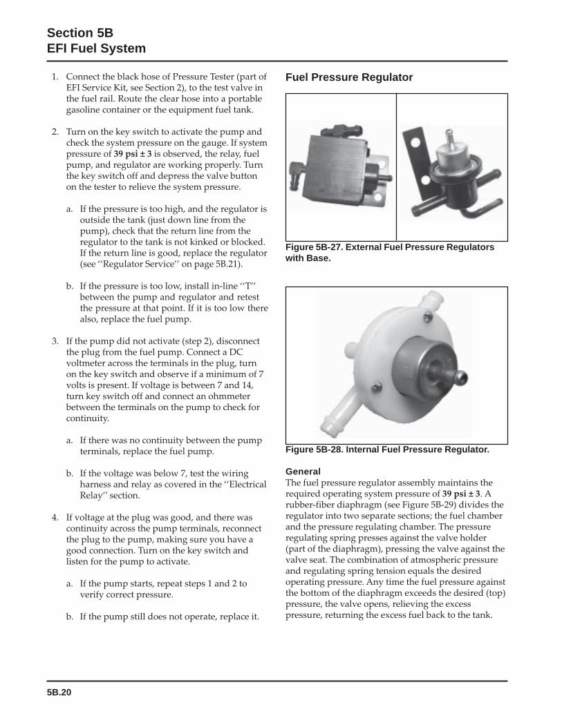
5B.20
Section 5BEFI Fuel System
1. Connect the black hose of Pressure Tester (part ofEFI Service Kit, see Section 2), to the test valve inthe fuel rail. Route the clear hose into a portablegasoline container or the equipment fuel tank.
2. Turn on the key switch to activate the pump andcheck the system pressure on the gauge. If systempressure of 39 psi ± 3 is observed, the relay, fuelpump, and regulator are working properly. Turnthe key switch off and depress the valve buttonon the tester to relieve the system pressure.
a. If the pressure is too high, and the regulator isoutside the tank (just down line from thepump), check that the return line from theregulator to the tank is not kinked or blocked.If the return line is good, replace the regulator(see ‘‘Regulator Service’’ on page 5B.21).
b. If the pressure is too low, install in-line ‘‘T’’between the pump and regulator and retestthe pressure at that point. If it is too low therealso, replace the fuel pump.
3. If the pump did not activate (step 2), disconnectthe plug from the fuel pump. Connect a DCvoltmeter across the terminals in the plug, turnon the key switch and observe if a minimum of 7volts is present. If voltage is between 7 and 14,turn key switch off and connect an ohmmeterbetween the terminals on the pump to check forcontinuity.
a. If there was no continuity between the pumpterminals, replace the fuel pump.
b. If the voltage was below 7, test the wiringharness and relay as covered in the ‘‘ElectricalRelay’’ section.
4. If voltage at the plug was good, and there wascontinuity across the pump terminals, reconnectthe plug to the pump, making sure you have agood connection. Turn on the key switch andlisten for the pump to activate.
a. If the pump starts, repeat steps 1 and 2 toverify correct pressure.
b. If the pump still does not operate, replace it.
Figure 5B-28. Internal Fuel Pressure Regulator.
GeneralThe fuel pressure regulator assembly maintains therequired operating system pressure of 39 psi ± 3. Arubber-fiber diaphragm (see Figure 5B-29) divides theregulator into two separate sections; the fuel chamberand the pressure regulating chamber. The pressureregulating spring presses against the valve holder(part of the diaphragm), pressing the valve against thevalve seat. The combination of atmospheric pressureand regulating spring tension equals the desiredoperating pressure. Any time the fuel pressure againstthe bottom of the diaphragm exceeds the desired (top)pressure, the valve opens, relieving the excesspressure, returning the excess fuel back to the tank.
Fuel Pressure Regulator
Figure 5B-27. External Fuel Pressure Regulatorswith Base.
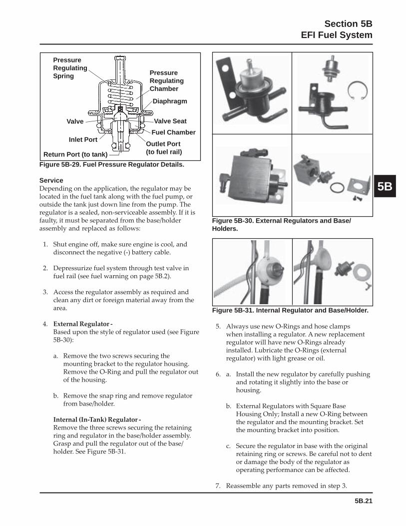
5B.21
Section 5BEFI Fuel System
5B
Figure 5B-29. Fuel Pressure Regulator Details.
ServiceDepending on the application, the regulator may belocated in the fuel tank along with the fuel pump, oroutside the tank just down line from the pump. Theregulator is a sealed, non-serviceable assembly. If it isfaulty, it must be separated from the base/holderassembly and replaced as follows:
1. Shut engine off, make sure engine is cool, anddisconnect the negative (-) battery cable.
2. Depressurize fuel system through test valve infuel rail (see fuel warning on page 5B.2).
3. Access the regulator assembly as required andclean any dirt or foreign material away from thearea.
4. External Regulator -Based upon the style of regulator used (see Figure5B-30):
a. Remove the two screws securing themounting bracket to the regulator housing.Remove the O-Ring and pull the regulator outof the housing.
b. Remove the snap ring and remove regulatorfrom base/holder.
Internal (In-Tank) Regulator -Remove the three screws securing the retainingring and regulator in the base/holder assembly.Grasp and pull the regulator out of the base/holder. See Figure 5B-31.
Outlet Port(to fuel rail)Return Port (to tank)
Inlet Port
PressureRegulatingSpring Pressure
RegulatingChamber
Diaphragm
Valve Valve Seat
Fuel Chamber
Figure 5B-31. Internal Regulator and Base/Holder.
5. Always use new O-Rings and hose clampswhen installing a regulator. A new replacementregulator will have new O-Rings alreadyinstalled. Lubricate the O-Rings (externalregulator) with light grease or oil.
6. a. Install the new regulator by carefully pushingand rotating it slightly into the base orhousing.
b. External Regulators with Square BaseHousing Only; Install a new O-Ring betweenthe regulator and the mounting bracket. Setthe mounting bracket into position.
c. Secure the regulator in base with the originalretaining ring or screws. Be careful not to dentor damage the body of the regulator asoperating performance can be affected.
7. Reassemble any parts removed in step 3.
Figure 5B-30. External Regulators and Base/Holders.
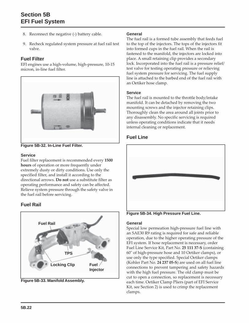
5B.22
Section 5BEFI Fuel System
8. Reconnect the negative (-) battery cable.
9. Recheck regulated system pressure at fuel rail testvalve.
Fuel FilterEFI engines use a high-volume, high-pressure, 10-15micron, in-line fuel filter.
GeneralThe fuel rail is a formed tube assembly that feeds fuelto the top of the injectors. The tops of the injectors fitinto formed cups in the fuel rail. When the rail isfastened to the manifold, the injectors are locked intoplace. A small retaining clip provides a secondarylock. Incorporated into the fuel rail is a pressure relief/test valve for testing operating pressure or relievingfuel system pressure for servicing. The fuel supplyline is attached to the barbed end of the fuel rail withan Oetiker hose clamp.
ServiceThe fuel rail is mounted to the throttle body/intakemanifold. It can be detached by removing the twomounting screws and the injector retaining clips.Thoroughly clean the area around all joints prior toany disassembly. No specific servicing is requiredunless operating conditions indicate that it needsinternal cleaning or replacement.
Fuel Line
Figure 5B-32. In-Line Fuel Filter.
ServiceFuel filter replacement is recommended every 1500hours of operation or more frequently underextremely dusty or dirty conditions. Use only thespecified filter, and install it according to thedirectional arrows. Do not use a substitute filter asoperating performance and safety can be affected.Relieve system pressure through the safety valve inthe fuel rail before servicing.
Fuel Rail
Figure 5B-34. High Pressure Fuel Line.
GeneralSpecial low permeation high-pressure fuel line withan SAE30 R9 rating is required for safe and reliableoperation, due to the higher operating pressure of theEFI system. If hose replacement is necessary, orderFuel Line Service Kit, Part No. 25 111 37-S (containing60" of high-pressure hose and 10 Oetiker clamps), oruse only the type specified. Special Oetiker clamps(Kohler Part No. 24 237 05-S) are used on all fuel lineconnections to prevent tampering and safety hazardswith the high fuel pressure. The old clamp must becut to open a connection, so replacement is necessaryeach time. Oetiker Clamp Pliers (part of EFI ServiceKit, see Section 2) is used to crimp the replacementclamps.
TPS
FuelInjector
Locking Clip
Fuel Rail
Figure 5B-33. Manifold Assembly.

5B.23
Section 5BEFI Fuel System
5B
For starting and warm up, the ECU will adjust thefuel and ignition timing, based upon ambienttemperature, engine temperature, and loads present.In cold conditions, the idle speed will probably behigher than normal for a few moments. Under otherconditions, the idle speed may actually start lowerthan normal, but gradually increase to the establishedsetting as operation continues. Do not attempt tocircumvent this warm up period, or readjust the idlespeed during this time. The engine must be completelywarmed up for accurate idle speed adjustment.
Adjustment Procedure1. Make sure there are no fault codes present in the
ECU memory.
2. Start the engine and allow it to fully warm upand establish closed looped operation(approximately 5-10 min.).
3. Place the throttle control in the ‘‘idle/slow’’position and check the idle speed with atachometer. Turn the idle speed screw in or out asrequired to obtain 1500 RPM, or the idle speedspecified by the equipment manufacturer.
4. The low idle speed adjustment can affect the highspeed setting. Move the throttle control to the fullthrottle position and check the high speed. Adjustas necessary to 3750 RPM (no load), or the speedspecified by the equipment manufacturer.
Idle Speed Screw Dampening SpringA small dampening spring (Kohler Part No.24 089 42-S) is attached to the end of the idle speedscrew of some EFI engines to help stabilize no loadoperating speeds. See Figure 5B-36.
Figure 5B-35. Upper Intake Manifold.
GeneralThe EFI engines have no carburetor, so the throttlefunction (regulate incoming combustion airflow) isincorporated in the intake manifold assembly. Themanifold consists of a one-piece aluminum castingwhich also provides mounting for the fuel injectors,throttle position sensor, fuel rail, air baffle, idle speedscrew, and air cleaner assembly.
ServiceThe throttle body/intake manifold is serviced as anassembly, with the throttle shaft, throttle plates, andidle speed adjusting screw installed. The throttle shaftrotates on needle bearings (non-serviceable), cappedwith rubber seals to prevent air leaks.
Idle Speed Adjustment (RPM)
GeneralThe idle speed is the only adjustment that may beperformed on the EFI system. The standard idle speedsetting for EFI engines is 1500 RPM, but certainapplications might require a different setting. Checkthe equipment manufacturer’s recommendation.
Fuel Rail
Throttle BodyIntake Manifold
Low Idle SpeedAdjusting Screw
CAUTION:Fuel lines between the fuel pump and fuel rail must be madefrom SAE 30 R9 fuel line. Standard fuel line (SAE 30 R7)may only be used between the fuel tank and pump (5/16”ID) and for the return line from the pressure regulator tothe tank (1/4” ID). All high-pressure fuel line connectionsmust be secured with Oetiker Clamps (Kohler Part No.24 237 05-S), installed/crimped with the correspondingpliers.
Throttle Body/Intake Manifold Assembly
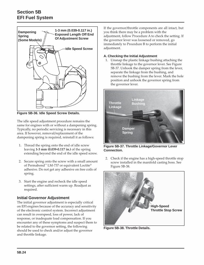
5B.24
Section 5BEFI Fuel System
If the governor/throttle components are all intact, butyou think there may be a problem with theadjustment, follow Procedure A to check the setting. Ifthe governor lever was loosened or removed, goimmediately to Procedure B to perform the initialadjustment.
A. Checking the Initial Adjustment1. Unsnap the plastic linkage bushing attaching the
throttle linkage to the governor lever. See Figure5B-37. Unhook the damper spring from the lever,separate the linkage from the bushing, andremove the bushing from the lever. Mark the holeposition and unhook the governor spring fromthe governor lever.
Figure 5B-36. Idle Speed Screw Details.
The idle speed adjustment procedure remains thesame for engines with or without a dampening spring.Typically, no periodic servicing is necessary in thisarea. If however, removal/replacement of thedampening spring is required, reinstall it as follows:
1. Thread the spring onto the end of idle screwleaving 1-3 mm (0.039-0.117 in.) of the springextending beyond the end of the idle speed screw.
2. Secure spring onto the screw with a small amountof Permabond™ LM-737 or equivalent Loctite®
adhesive. Do not get any adhesive on free coils ofspring.
3. Start the engine and recheck the idle speedsettings, after sufficient warm up. Readjust asrequired.
Initial Governor AdjustmentThe initial governor adjustment is especially criticalon EFI engines because of the accuracy and sensitivityof the electronic control system. Incorrect adjustmentcan result in overspeed, loss of power, lack ofresponse, or inadequate load compensation. If youencounter any of these symptoms and suspect them tobe related to the governor setting, the followingshould be used to check and/or adjust the governorand throttle linkage.
Figure 5B-38. Throttle Details.
1-3 mm (0.039-0.117 in.)Exposed Length Off EndOf Adjustment Screw
Idle Speed Screw
DampeningSpring(Some Models)
LinkageBushingThrottle
Linkage
DamperSpring
High-SpeedThrottle Stop Screw
Figure 5B-37. Throttle Linkage/Governor LeverConnection.
2. Check if the engine has a high-speed throttle stopscrew installed in the manifold casting boss. SeeFigure 5B-38.
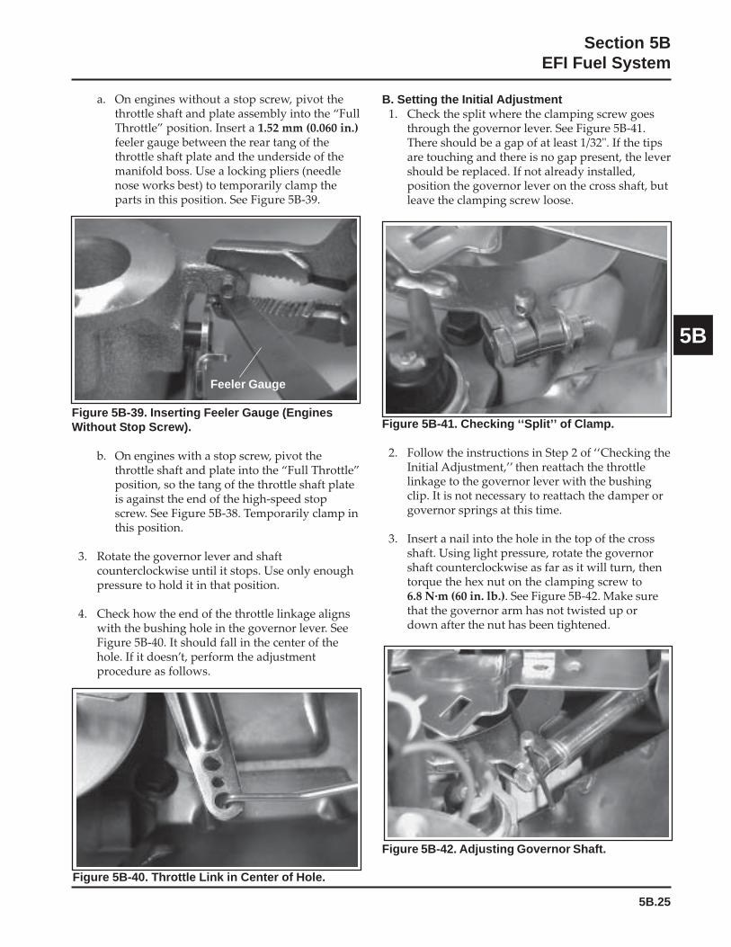
5B.25
Section 5BEFI Fuel System
5B
Figure 5B-39. Inserting Feeler Gauge (EnginesWithout Stop Screw).
b. On engines with a stop screw, pivot thethrottle shaft and plate into the “Full Throttle”position, so the tang of the throttle shaft plateis against the end of the high-speed stopscrew. See Figure 5B-38. Temporarily clamp inthis position.
3. Rotate the governor lever and shaftcounterclockwise until it stops. Use only enoughpressure to hold it in that position.
4. Check how the end of the throttle linkage alignswith the bushing hole in the governor lever. SeeFigure 5B-40. It should fall in the center of thehole. If it doesn’t, perform the adjustmentprocedure as follows.
B. Setting the Initial Adjustment1. Check the split where the clamping screw goes
through the governor lever. See Figure 5B-41.There should be a gap of at least 1/32". If the tipsare touching and there is no gap present, the levershould be replaced. If not already installed,position the governor lever on the cross shaft, butleave the clamping screw loose.
Feeler Gauge
Figure 5B-40. Throttle Link in Center of Hole.
Figure 5B-41. Checking ‘‘Split’’ of Clamp.
2. Follow the instructions in Step 2 of ‘‘Checking theInitial Adjustment,’’ then reattach the throttlelinkage to the governor lever with the bushingclip. It is not necessary to reattach the damper orgovernor springs at this time.
3. Insert a nail into the hole in the top of the crossshaft. Using light pressure, rotate the governorshaft counterclockwise as far as it will turn, thentorque the hex nut on the clamping screw to6.8 N·m (60 in. lb.). See Figure 5B-42. Make surethat the governor arm has not twisted up ordown after the nut has been tightened.
Figure 5B-42. Adjusting Governor Shaft.
a. On engines without a stop screw, pivot thethrottle shaft and plate assembly into the “FullThrottle” position. Insert a 1.52 mm (0.060 in.)feeler gauge between the rear tang of thethrottle shaft plate and the underside of themanifold boss. Use a locking pliers (needlenose works best) to temporarily clamp theparts in this position. See Figure 5B-39.

5B.26
Section 5BEFI Fuel System
4. Verify that the governor has been set correctly.With the linkage still retained in the “FullThrottle” position (Step 2), unsnap the bushingclip, separate the linkage from the bushing, andremove the bushing from the lever. Follow Steps3 and 4 in ‘‘Checking the Initial Adjustment’’.
5. Reconnect the dampening spring into itsgovernor lever hole from the bottom. Reinstallthe bushing and reattach the throttle linkage. SeeFigure 5B-37. Reattach the governor spring in themarked hole.
6. Start the engine and allow it to fully warm upand establish closed loop operation(approximately 5-10 min.). Check the speedsettings and adjust as necessary, first the low idlespeed, and then the high speed setting.
Troubleshooting
GeneralWhen troubleshooting a problem on an engine withEFI, basic engine operating problems must beeliminated first before faulting the EFI systemcomponents. What appears to be an EFI problemcould be something as simple as a fuel tank withdebris in the bottom or a plugged vent. Be sure theengine is in good mechanical operating condition, andall other systems are functional before attempting totroubleshoot the EFI system.
Troubleshooting Guide
Engine starts hard or fails to start when cold1. Fuel pump not running2. Faulty spark plugs3. Old/stale fuel4. Incorrect fuel pressure5. Speed sensor loose or faulty6. TPS offset incorrect (initialization)7. TPS faulty8. Engine temperature sensor faulty9. Faulty coils
10. Low system voltage11. Faulty injectors
Engine starts hard or fails to start when hot1. Faulty spark plugs2. Fuel pump not running3. Fuel pressure low4. Insufficient fuel delivery5. TPS offset incorrect (Initialization)6. Speed sensor loose or faulty7. TPS faulty8. Engine temperature sensor faulty9. Faulty injectors
Engine stalls or idles roughly (cold or warm)1. Faulty spark plugs2. Insufficient fuel delivery3. TPS offset incorrect4. TPS faulty5. Faulty engine temperature sensor6. Faulty injectors
Engine misses, hesitates, or stalls under load1. Fuel injector(s), fuel filter, fuel line, or fuel pick-
up dirty/restricted2. Dirty air cleaner3. Insufficient fuel pressure or fuel delivery4. Vacuum (intake air) leak5. Improper governor setting, adjustment or
operation6. Speed sensor malfunction7. TPS faulty, mounting problem or "TPS
Initialization Procedure" incorrect8. Bad coil(s), spark plug(s), or wires
Low Power1. Faulty/malfunctioning ignition system2. Dirty air filter3. Insufficient fuel delivery4. Improper governor adjustment5. Plugged/restricted exhaust6. One injector not working7. Basic engine problem exists8. TPS faulty or mounting exists9. Throttle plates in throttle body/intake manifold
not fully opening to WOT stop (if so equipped)
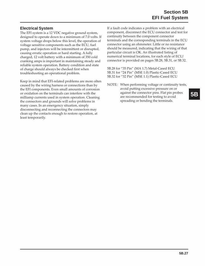
5B.27
Section 5BEFI Fuel System
5B
Electrical SystemThe EFI system is a 12 VDC negative ground system,designed to operate down to a minimum of 7.0 volts. Ifsystem voltage drops below this level, the operation ofvoltage sensitive components such as the ECU, fuelpump, and injectors will be intermittent or disrupted,causing erratic operation or hard starting. A fullycharged, 12 volt battery with a minimum of 350 coldcranking amps is important in maintaining steady andreliable system operation. Battery condition and stateof charge should always be checked first whentroubleshooting an operational problem.
Keep in mind that EFI-related problems are more oftencaused by the wiring harness or connections than bythe EFI components. Even small amounts of corrosionor oxidation on the terminals can interfere with themilliamp currents used in system operation. Cleaningthe connectors and grounds will solve problems inmany cases. In an emergency situation, simplydisconnecting and reconnecting the connectors mayclean up the contacts enough to restore operation, atleast temporarily.
If a fault code indicates a problem with an electricalcomponent, disconnect the ECU connector and test forcontinuity between the component connectorterminals and the corresponding terminals in the ECUconnector using an ohmmeter. Little or no resistanceshould be measured, indicating that the wiring of thatparticular circuit is OK. An illustrated listing ofnumerical terminal locations, for each style of ECU/connector is provided on pages 5B.28, 5B.31, or 5B.32.
5B.28 for “35 Pin” (MA 1.7) Metal-Cased ECU5B.31 for “24 Pin” (MSE 1.0) Plastic-Cased ECU5B.32 for “32 Pin” (MSE 1.1) Plastic-Cased ECU
NOTE: When performing voltage or continuity tests,avoid putting excessive pressure on oragainst the connector pins. Flat pin probesare recommended for testing to avoidspreading or bending the terminals.

5B.28
Section 5BEFI Fuel System
Pin #
123456789
1011121314151617181920212223242526272829303132333435
Component
Ignition Coil #1Not used
Engine Speed SensorECU Production Test Terminal
Not UsedNot UsedNot Used
TPS Initialization TerminalEngine Ground
O2 Sensor
Not UsedThrottle Position Sensor
Not UsedOil Temperature Sensor
Not UsedECU Permanent Battery VoltageECU Switched Battery Voltage
Engine GroundIgnition Coil #2Vehicle Ground
Engine Speed SensorNot UsedNot UsedNot Used
Throttle Position SensorNot Used
Throttle Position Sensor/Oil Temperature SensorPower Relay
Not UsedNot Used
Malfunction Indicator LightNot Used
Vehicle GroundNot Used
Fuel Injectors
123456789101112131415161718
1920212223242526272829303132333435
“35 Pin” (MA 1.7) Metal-Cased ECU Systems
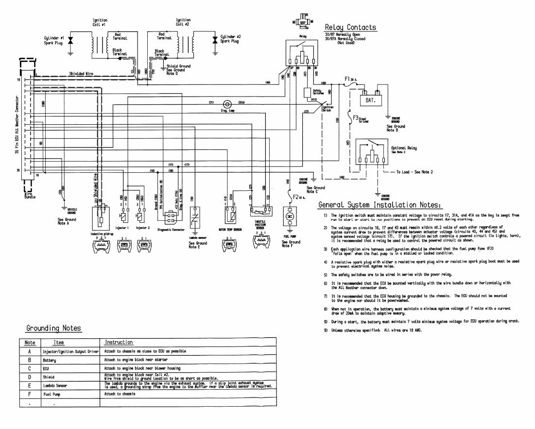
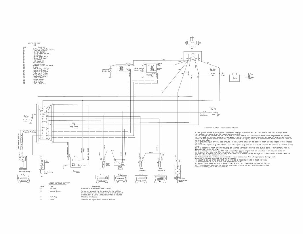
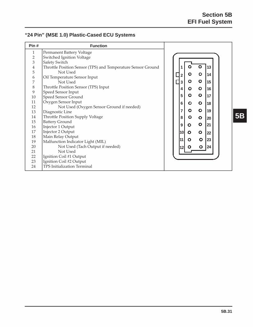
5B.31
Section 5BEFI Fuel System
5B
“24 Pin” (MSE 1.0) Plastic-Cased ECU Systems
Pin #
123456789
101112131415161718192021222324
Function
1
Permanent Battery VoltageSwitched Ignition VoltageSafety SwitchThrottle Position Sensor (TPS) and Temperature Sensor Ground
Not UsedOil Temperature Sensor Input
Not UsedThrottle Position Sensor (TPS) InputSpeed Sensor InputSpeed Sensor GroundOxygen Sensor Input
Not Used (Oxygen Sensor Ground if needed)Diagnostic LineThrottle Position Supply VoltageBattery GroundInjector 1 OutputInjector 2 OutputMain Relay OutputMalfunction Indicator Light (MIL)
Not Used (Tach Output if needed)Not Used
Ignition Coil #1 OutputIgnition Coil #2 OutputTPS Initialization Terminal
2
3
4
5
6
7
8
9
10
11
12
13
14
15
16
17
18
19
20
21
22
23
24
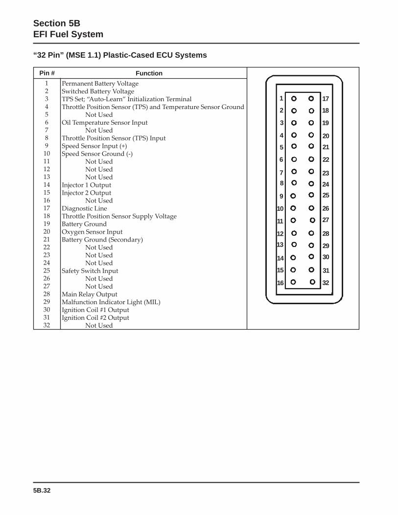
5B.32
Section 5BEFI Fuel System
“32 Pin” (MSE 1.1) Plastic-Cased ECU Systems
Pin #
123456789
1011121314151617181920212223242526272829303132
Function
Permanent Battery VoltageSwitched Battery VoltageTPS Set; “Auto-Learn” Initialization TerminalThrottle Position Sensor (TPS) and Temperature Sensor Ground
Not UsedOil Temperature Sensor Input
Not UsedThrottle Position Sensor (TPS) InputSpeed Sensor Input (+)Speed Sensor Ground (-)
Not UsedNot UsedNot Used
Injector 1 OutputInjector 2 Output
Not UsedDiagnostic LineThrottle Position Sensor Supply VoltageBattery GroundOxygen Sensor InputBattery Ground (Secondary)
Not UsedNot UsedNot Used
Safety Switch InputNot UsedNot Used
Main Relay OutputMalfunction Indicator Light (MIL)Ignition Coil #1 OutputIgnition Coil #2 Output
Not Used
1
2
3
4
5
6
7
8
9
10
11
12
17
18
19
20
21
22
23
24
25
26
27
28
13
14
29
30
15
16
31
32
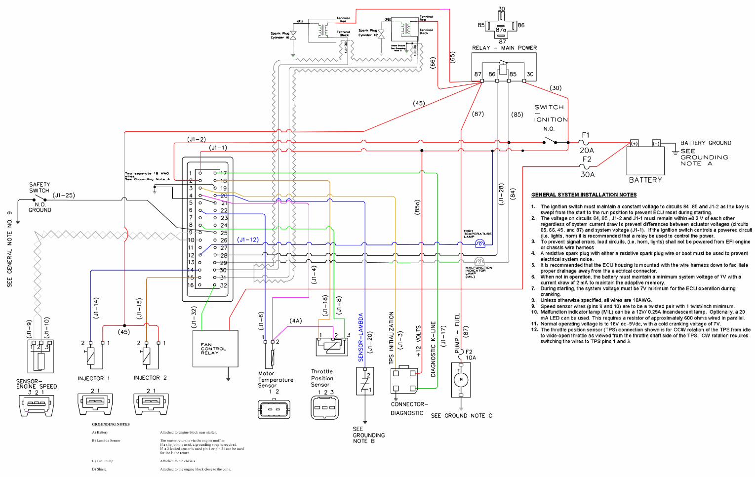
5B.34
Section 5BEFI Fuel System
Fuel System
WARNING: Fuel System Under Pressure!The fuel system operates under high pressure. Systempressure must be relieved through the test valve in the fuelrail prior to servicing or removing any fuel systemcomponents. Do not smoke or work near heaters or other firehazards. Have a fire extinguisher handy and work only in awell-ventilated area.
The function of the fuel system is to provide sufficientdelivery of fuel at the system operating pressure of 39psi ± 3. If an engine starts hard, or turns over but willnot start, it may indicate a problem with the EFI fuelsystem. A quick test will verify if the system isoperating.
1. Disconnect and ground the spark plug leads.
2. Complete all safety interlock requirements andcrank the engine for approximately 3 seconds.
3. Remove the spark plugs and check for fuel at thetips.
a. If there is fuel at the tips of the spark plugs,the fuel pump and injectors are operating.
b. If there is no fuel at the tips of the spark plugs,check the following:
1. Make sure the fuel tank contains clean,fresh, proper fuel.
2. Make sure that vent in fuel tank is open.
3. Make sure fuel tank valve (if so equipped)is fully opened.
4. Make sure battery is supplying propervoltage.
5. Check that the fuses are good, and that allelectrical and fuel line connections aregood.
6. Test fuel pump and relay operation asdescribed earlier under ‘‘Fuel Pump –Service.’’
Fault CodesThe ECU continuously monitors engine operationagainst preset performance limits. If the operation isoutside the limits, the ECU activates the MIL andstores a diagnostic code in its fault memory. If thecomponent or system returns to proper function, theECU will eventually self-clear the fault code and turnoff the MIL. If the MIL stays illuminated, it warns thecustomer that dealer service is required. Upon receipt,the dealer technician can access the fault code(s) tohelp determine what portion of the system ismalfunctioning. The 2-digit blink codes availablebased upon the style of ECU are listed on pages 5B.35-5B.36.
The codes are accessed through the key switch anddisplayed as blinks or flashes of the MIL. Access thecodes as follows:
1. Start with the key switch off.
2. Turn the key switch on-off-on-off-on, leaving iton in the third sequence. The time betweensequences must be less than 2.5 seconds.
3. Any stored fault codes will then be displayed as aseries of MIL blinks (from 2 to 6) representing thefirst digit, followed by a pause, and another seriesof blinks (from 1 to 6) for the second digit (seeFigure 5B-43).
a. It’s a good idea to write down the codes asthey appear, as they may not be in numericalsequence.
b. Code 61 will always be the last codedisplayed, indicating the end of codetransmission. If code 61 appears immediately,no other fault codes are present.

5B.35
Section 5BEFI Fuel System
5B
Long PauseShort Pauses
Code 323 2
Code 61
16
Long Pause
Light remains on at end of transmission
1. Diagnostic display initiated through ignition key sequencing.
2.
Figure 5B-43.
After the problem has been corrected, the fault codes may be cleared as follows.
1. Disconnect the negative (-) battery cable from battery terminal, or remove the main fuse for the ECU forapproximately 1 minute.
2. Reconnect the cable and tighten securely, or reinstall the main fuse. Start the engine and allow it to run forseveral minutes. The MIL should remain off if the problem was corrected, and the fault codes should notreappear (codes 31, 32, 33, and 34 may require 10-15 minutes of running to reappear).
The following chart lists the fault codes, what they correspond to, and what the visual indications will be.Following the chart is a list of the individual codes with an explanation of what triggers them, what symptomsmight be expected, and the probable causes.
Diagnostic Code Summary
Example of Diagnostic Display
Long Pause
3.
4.
5.
6.
7.
knilBedoC
2DBOedoC-P
elbacilppA"niP23":ot)1.1ESM(-tsyS/UCE
ylnOme
noitpircseDeruliaFronoitcennoC
"niP53")7.1AM(
desaC-lateMmetsyS/UCE
"niP42")0.1ESM(
desaC-citsalPmetsyS/UCE
"niP23")1.1ESM(
desaC-citsalPmetsyS/UCE
etoN
- - langiSMPRoN Y Y Y
12 5330P noitazinorhcnySfossoL Y Y Y
22 0210P elbisualpmIlangiS-SPT N N N 2
22 2210P dnuorGottiucriCtrohSronepO-SPT Y Y Y
22 3210P yrettaBottiucriCtrohS-SPT Y Y Y
32 1060P UCEevitcefeD Y Y Y
42 rosneSdeepSenignE Y Y Y 9
13 4710P naeLootmetsyS Y Y Y 6
cont. on next page

5B.36
Section 5BEFI Fuel System
knilBedoC
2DBOedoC-P
elbacilppA"niP23":ot)1.1ESM(-tsyS/UCE
ylnOme
noitpircseDeruliaFronoitcennoC
"niP53")7.1AM(
desaC-lateMmetsyS/UCE
"niP42")0.1ESM(
desaC-citsalPmetsyS/UCE
"niP23")1.1ESM(
desaC-citsalPmetsyS/UCE
etoN
13 2310P O2 yrettaBotdetrohS:tiucriCrosneS Y N Y 3
23 4310P O2 detceteDytivitcAoN:tiucriCrosneS N N N 8
33 5710P hciRootmetsyS Y Y Y 8,7
33 0200P O2 timiLreppUtalortnoCrosneS Y Y Y 8
43 1710P dehcaeRtimiLnoitpadAmumixaM Y Y Y 8
43 2710P dehcaeRtimiLnoitpadAmuminiM Y Y Y 8
24 7110PotdetrohS:tiucriCrosneSerutarepmeT
dnuorGY Y Y
24 8110ProtiucriCnepO:tiucriCrosneSerutarepmeT
yrettaBottrohSY Y Y
34 A/NtesffOSPT-nraelotuAgnitelpmoCeruliaF
timilelbawollamuminimwolebA/N A/N Y
44 A/NtesffoSPT-nraelotuAgnitelpmoCeruliaF
timilelbawollamumixamevobaA/N A/N Y
15 0621P tiucriCnepO-1rotcejnI A/N A/N Y
15 1620P dnuorGottiucriCtrohS-1rotcejnI A/N A/N Y
15 2620P yrettaBottiucriCtrohS-1rotcejnI A/N A/N Y
25 3621P tiucriCnepO-2rotcejnI A/N A/N Y
25 4620P dnuorGottiucriCtrohS-2rotcejnI A/N A/N Y
25 5620P yrettaBottiucriCtrohS-2rotcejnI A/N A/N Y
55 1561P tiucriCnepO-pmaLcitsongaiD A/N A/N Y
55 2561P dnuorGottiucriCtrohS-pmaLcitsongaiD A/N A/N Y
55 3561P yrettaBottiucriCtrohS-pmaLcitsongaiD A/N A/N Y
65 1321P tiucriCnepO-yaleRpmuP A/N A/N Y
65 2321P dnuorGottiucriCtrohS-yaleRpmuP A/N A/N Y
65 3321P yrettaBottiucriCtrohS-yaleRpmuP A/N A/N Y
16 noissimsnarTedoCfodnE Y Y Y
Note:1. Idle Switch not used.2. Diagnostic of "TPS - Signal Implausible" is disabled in code.3. "O
2 Sensor Short to Battery" diagnostic detection is disabled with SAS fuel-cutoff calibrated out.
4. Air Temperature Sensor not used.5. "Temperature Sensor Signal Implausible": diagnostic detection is calibrated out, with TPLAUS set to -50°C.6. System too Lean used to be "O
2 Sensor - Short to Ground (P0131)."
7. "System too Rich" used to be "O2 Sensor Control at Lower Limit (P0019)."
8. Obtainable only with ECU 24 584 28-S or later.9. Will not blink out.
5B.37
Section 5BEFI Fuel System
5B
Code: 21Source: Engine Speed SensorExplanation: ECU receiving inconsistent tooth
count signals from speed sensor.Expected EngineResponse: Possible misfire as ECU attempts to
resynchronize, during which time fueland spark calculations are not made.
Possible Causes:1. Engine Speed Sensor Related
a. Sensor connector or wiring.b. Sensor loose or incorrect air gap.c. Flywheel key sheared.
2. Speed Sensor Ring Gear Relateda. Damaged teeth.b. Varying gap (gear loose/out of alignment).
3. Engine Wiring Harness Related“35 Pin” (MA 1.7) Metal-Cased ECU:a. Pin circuits 3 and/or 21 wiring or connectors.b. Shielding for pin circuits 3 and/or 21 damaged
or not properly grounded.c. Poor or improper grounds in system (battery,
ECU, oxygen sensor, shielding, fuel pump,ignition output).
d. Pin circuits 3 and/or 21 routed near noisyelectrical signals (coils, spark plug lead, plugconnector).
3. Engine Wiring Harness Related“24 Pin” (MSE 1.0) Plastic-Cased ECU:a. Pin circuits 9 and/or 10 wiring or connectors.b. Shielding for pin circuits 9 and/or 10 damaged
or not properly grounded.c. Poor or improper grounds in system (battery,
ECU oxygen sensor, shielding, fuel pump,ignition output).
d. Pin circuits 9 and/or 10 routed near noisyelectrical signals (coils, spark plug lead, plugconnector).
3. Engine Wiring Harness Related“32 Pin” (MSE 1.1) Plastic-Cased ECU:a. Pin circuits 9 and/or 10 wiring or connectors.b. Shielding for pin circuits 9 and/or 10 damaged
or not properly grounded.c. Poor or improper grounds in system (battery,
ECU, oxygen sensor, shielding, fuel pump,ignition output).
d. Pin circuits 9 and/or 10 routed near noisyelectrical signals (coils, spark plug lead, plugconnector).
4. ECU/Harness Relateda. ECU-to-harness connection problem.
5. Ignition System Relateda. Non-resistor spark plug(s) used.
Code: 22Source: Throttle Position Sensor (TPS)Explanation: Unrecognizable signal is being sent
from sensor (too high, too low,inconsistent).
Expected EngineResponse: A “limp-home” operating mode
occurs, with an overall decrease inoperating performance and efficiency.Fuel delivery is based upon theoxygen sensor and five mappedvalues only. Rich running (blacksmoke) will occur until “closed loop”operation is initiated. A stumble ormisfire on hard acceleration and/orerratic operation may be exhibited.
Possible Causes:1. TPS Sensor Related
a. Sensor connector or wiring.b. Sensor output affected or disrupted by dirt,
grease, oil, wear, or breather tube position(must be to side opposite the TPS).
c. Sensor loose on throttle body manifold.
2. Throttle Body Relateda. Throttle shaft or bearings worn/damaged.
3. Engine Wiring Harness Related“35 Pin” (MA 1.7) Metal-Cased ECU:a. Pin circuits 12, 25 and/or 27 damaged (wiring
or connectors).b. Pin circuits 12, 25 and/or 27 routed near noisy
electrical signal (coils, alternator).c. Intermittent 5 volt source from ECU (pin
circuit 25).
3. Engine Wiring Harness Related“24 Pin” (MSE 1.0) Plastic-Cased ECU:a. Pin circuits 4, 8, and/or 14 damaged (wiring,
connectors).b. Pin circuits 4, 8, and/or 14 routed near noisy
electrical signal (coils, alternator).c. Intermittent 5 volt source from ECU (pin
circuit 14).
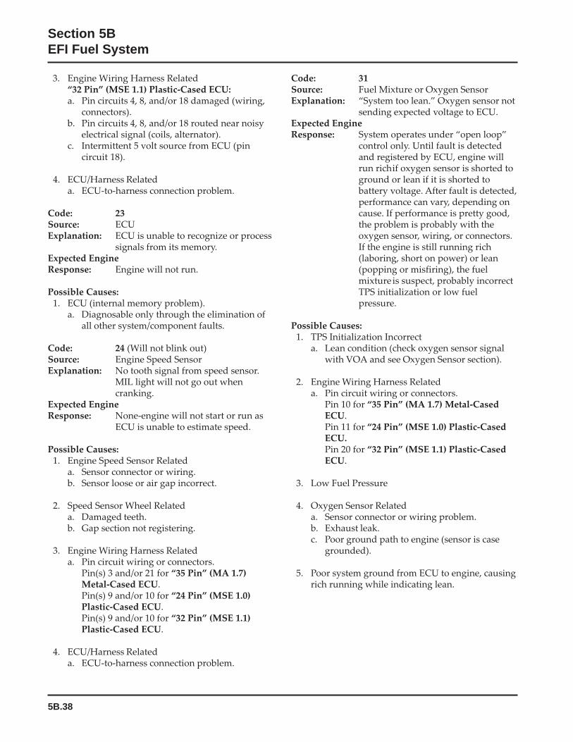
5B.38
Section 5BEFI Fuel System
3. Engine Wiring Harness Related“32 Pin” (MSE 1.1) Plastic-Cased ECU:a. Pin circuits 4, 8, and/or 18 damaged (wiring,
connectors).b. Pin circuits 4, 8, and/or 18 routed near noisy
electrical signal (coils, alternator).c. Intermittent 5 volt source from ECU (pin
circuit 18).
4. ECU/Harness Relateda. ECU-to-harness connection problem.
Code: 23Source: ECUExplanation: ECU is unable to recognize or process
signals from its memory.Expected EngineResponse: Engine will not run.
Possible Causes:1. ECU (internal memory problem).
a. Diagnosable only through the elimination ofall other system/component faults.
Code: 24 (Will not blink out)Source: Engine Speed SensorExplanation: No tooth signal from speed sensor.
MIL light will not go out whencranking.
Expected EngineResponse: None-engine will not start or run as
ECU is unable to estimate speed.
Possible Causes:1. Engine Speed Sensor Related
a. Sensor connector or wiring.b. Sensor loose or air gap incorrect.
2. Speed Sensor Wheel Relateda. Damaged teeth.b. Gap section not registering.
3. Engine Wiring Harness Relateda. Pin circuit wiring or connectors.
Pin(s) 3 and/or 21 for “35 Pin” (MA 1.7)Metal-Cased ECU.Pin(s) 9 and/or 10 for “24 Pin” (MSE 1.0)Plastic-Cased ECU.Pin(s) 9 and/or 10 for “32 Pin” (MSE 1.1)Plastic-Cased ECU.
4. ECU/Harness Relateda. ECU-to-harness connection problem.
Code: 31Source: Fuel Mixture or Oxygen SensorExplanation: “System too lean.” Oxygen sensor not
sending expected voltage to ECU.Expected EngineResponse: System operates under “open loop”
control only. Until fault is detectedand registered by ECU, engine willrun richif oxygen sensor is shorted toground or lean if it is shorted tobattery voltage. After fault is detected,performance can vary, depending oncause. If performance is pretty good,the problem is probably with theoxygen sensor, wiring, or connectors.If the engine is still running rich(laboring, short on power) or lean(popping or misfiring), the fuelmixture is suspect, probably incorrectTPS initialization or low fuelpressure.
Possible Causes:1. TPS Initialization Incorrect
a. Lean condition (check oxygen sensor signalwith VOA and see Oxygen Sensor section).
2. Engine Wiring Harness Relateda. Pin circuit wiring or connectors.
Pin 10 for “35 Pin” (MA 1.7) Metal-CasedECU.Pin 11 for “24 Pin” (MSE 1.0) Plastic-CasedECU.Pin 20 for “32 Pin” (MSE 1.1) Plastic-CasedECU.
3. Low Fuel Pressure
4. Oxygen Sensor Relateda. Sensor connector or wiring problem.b. Exhaust leak.c. Poor ground path to engine (sensor is case
grounded).
5. Poor system ground from ECU to engine, causingrich running while indicating lean.

5B.39
Section 5BEFI Fuel System
5B
Code: 32Source: Oxygen SensorExplanation: No change in the sensor output
signal.Expected EngineResponse: “Open loop” operation only, may
cause a drop in system performanceand fuel efficiency.
Possible Causes:1. Engine Wiring Harness Related
a. Pin circuit wiring or connectors.Pin 10 for “35 Pin” (MA 1.7) Metal-CasedECU.Pin 11 for “24 Pin” (MSE 1.0) Plastic-CasedECU.Pin 20 for “32 Pin” (MSE 1.1) Plastic-CasedECU.
2. Oxygen Sensor Relateda. Sensor connector or wiring problem.b. Sensor contaminated or damaged.c. Sensor below the minimum operating
temperature (375°C, 709°F).d. Poor ground path from sensor to engine
(sensor grounds through shell, see OxygenSensor section).
Code: 33Source: Oxygen Sensor/Fuel SystemExplanation: “System too rich.” Temporary fuel
adaptation control is at the upperlimit.
Expected EngineResponse: Erratic performance. Will run rich
(smoke).
Possible Causes:1. Fuel Supply Related (nothing lean – only rich)
a. Restricted return line causing excessive fuelpressure.
b. Fuel inlet screen plugged (in-tank fuel pumponly).
c. Incorrect fuel pressure at fuel rail.
2. Oxygen Sensor Relateda. Sensor connector or wiring problem.b. Sensor contaminated or damaged.c. Exhaust leak.d. Poor ground path.e. Pin circuit wiring or connectors.
Pin 10 for “35 Pin” (MA 1.7) Metal-CasedECU.Pin 11 for “24 Pin” (MSE 1.0) Plastic-CasedECU.
Pin 20 for “32 Pin” (MSE 1.1) Plastic-CasedECU.
3. TPS Sensor Relateda. Throttle plate position incorrectly set or
registered during “Initialization.’’b. TPS problem or malfunction.
4. Engine Wiring Harness Relateda. Difference in voltage between sensed voltage
(pin circuit 17 for metal-cased ECU, pincircuit 2 for plastic-cased ECU) and actualinjector voltage (circuit 45/45A).
5. Systems Relateda. Ignition (spark plug, plug wire, ignition coil.b. Fuel (fuel type/quality, injector, fuel pump,
fuelpressure.c. Combustion air (air cleaner dirty/restricted,
intake leak, throttle bores).d. Base engine problem (rings, valves).e. Exhaust system leak.f. Fuel in the crankcase oil.g. Blocked or restricted fuel return circuit to
tank.
6. ECU/Harness Relateda. ECU-to-harness connection problem.
Code: 34Source: Oxygen Sensor/Fuel System
ComponentsExplanation: Long term fuel adaptation control is
at the upper or lower limit.Expected EngineResponse: System operates “closed loop.” No
appreciable performance loss as longas the temporary adaptation canprovide sufficient compensation.
Possible Causes:1. Oxygen Sensor Related
a. Sensor connector or wiring problem.b. Sensor contaminated or damaged.c. Exhaust leak.d. Poor ground path.e. Pin circuit wiring or connectors.
Pin 10 for “35 Pin” (MA 1.7) Metal-CasedECU.Pin 11 for “24 Pin” (MSE 1.0) Plastic-CasedECU.Pin 20 for “32 Pin” (MSE 1.1) Plastic-CasedECU.
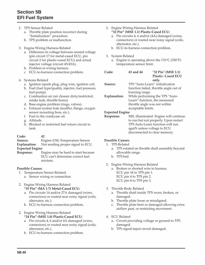
5B.40
Section 5BEFI Fuel System
2. Engine Wiring Harness Related“32 Pin” (MSE 1.1) Plastic-Cased ECU:a. Pin circuits 4, 6 and/or (4A) damaged (wires,
connectors) or routed near noisy signal (coils,alternator, etc.).
b. ECU-to-harness connection problem.
3. System Relateda. Engine is operating above the 176°C (350°F)
temperature sensor limit.
Code: 43 and 44 "32 Pin" (MSE 1.1)Plastic- Cased ECUonly.
Source: TPS “Auto-Learn” initializationfunction failed, throttle angle out oflearning range.
Explanation: While performing the TPS “Auto-Learn” function, the measuredthrottle angle was not withinacceptable limits.
Expected EngineResponse: MIL illuminated. Engine will continue
to run but not properly. Upon restartTPS Auto-Learn function will runagaiN unless voltage to ECUdisconnected to clear memory.
Possible Causes:1. TPS Related
a. TPS rotated on throttle shaft assembly beyondallowable range.
b. TPS bad.
2. Engine Wiring Harness Relateda. Broken or shorted wire in harness.
ECU pin 18 to TPS pin 1.ECU pin 4 to TPS pin 2.ECU pin 8 to TPS pin 3.
3. Throttle Body Relateda. Throttle shaft inside TPS worn, broken, or
damaged.b. Throttle plate loose or misaligned.c. Throttle plate bent or damaged allowing extra
airflow past, or restricting movement.
4. ECU Relateda. Circuit providing voltage or ground to TPS
damaged.b. TPS signal input circuit damaged.
2. TPS Sensor Relateda. Throttle plate position incorrect during
“Initialization” procedure.b. TPS problem or malfunction.
3. Engine Wiring Harness Relateda. Difference in voltage between sensed voltage
(pin circuit 17 for metal-cased ECU, pincircuit 2 for plastic-cased ECU) and actualinjector voltage (circuit 45/45A).
b. Problem in wiring harness.c. ECU-to-harness connection problem.
4. Systems Relateda. Ignition (spark plug, plug wire, ignition coil.b. Fuel (fuel type/quality, injector, fuel pressure,
fuel pump).c. Combustion air (air cleaner dirty/restricted,
intake leak, throttle bores).d. Base engine problem (rings, valves).e. Exhaust system leak (muffler, flange, oxygen
sensor mounting boss, etc.).f. Fuel in the crankcase oil.g. Altitude.h. Blocked or restricted fuel return circuit to
tank.
Code: 42Source: Engine (Oil) Temperature SensorExplanation: Not sending proper signal to ECU.Expected EngineResponse: Engine may be hard to start because
ECU can’t determine correct fuelmixture.
Possible Causes:1. Temperature Sensor Related.
a. Sensor wiring or connection.
2. Engine Wiring Harness Related“35 Pin” (MA 1.7) Metal-Cased ECU:a. Pin circuits 14 and/or 27A damaged (wires,
connectors) or routed near noisy signal (coils,alternator, etc.).
b. ECU-to-harness connection problem.
2. Engine Wiring Harness Related“24 Pin” (MSE 1.0) Plastic-Cased ECU:a. Pin circuits 4, 6 and/or 4A damaged (wires,
connectors) or routed near noisy signal (coils,alternator, etc.).
b. ECU-to-harness connection problem.
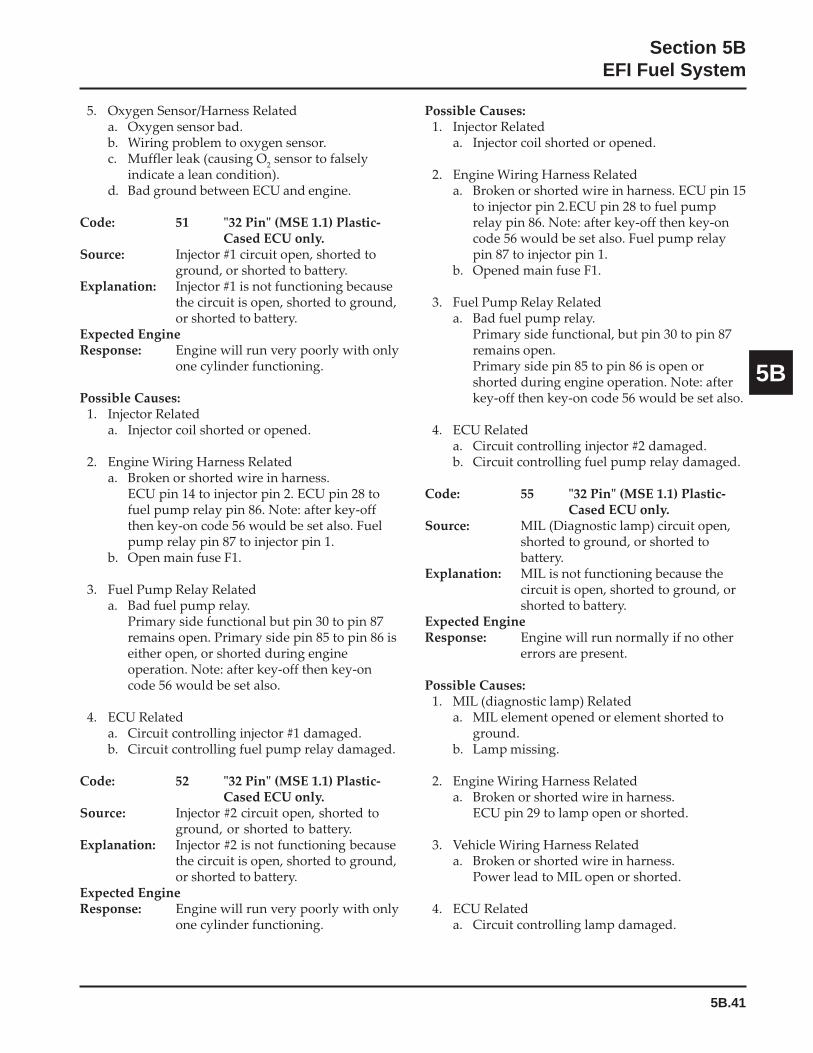
5B.41
Section 5BEFI Fuel System
5B
5. Oxygen Sensor/Harness Relateda. Oxygen sensor bad.b. Wiring problem to oxygen sensor.c. Muffler leak (causing O
2 sensor to falsely
indicate a lean condition).d. Bad ground between ECU and engine.
Code: 51 "32 Pin" (MSE 1.1) Plastic-Cased ECU only.
Source: Injector #1 circuit open, shorted toground, or shorted to battery.
Explanation: Injector #1 is not functioning becausethe circuit is open, shorted to ground,or shorted to battery.
Expected EngineResponse: Engine will run very poorly with only
one cylinder functioning.
Possible Causes:1. Injector Related
a. Injector coil shorted or opened.
2. Engine Wiring Harness Relateda. Broken or shorted wire in harness.
ECU pin 14 to injector pin 2. ECU pin 28 tofuel pump relay pin 86. Note: after key-offthen key-on code 56 would be set also. Fuelpump relay pin 87 to injector pin 1.
b. Open main fuse F1.
3. Fuel Pump Relay Relateda. Bad fuel pump relay.
Primary side functional but pin 30 to pin 87remains open. Primary side pin 85 to pin 86 iseither open, or shorted during engineoperation. Note: after key-off then key-oncode 56 would be set also.
4. ECU Relateda. Circuit controlling injector #1 damaged.b. Circuit controlling fuel pump relay damaged.
Code: 52 "32 Pin" (MSE 1.1) Plastic-Cased ECU only.
Source: Injector #2 circuit open, shorted toground, or shorted to battery.
Explanation: Injector #2 is not functioning becausethe circuit is open, shorted to ground,or shorted to battery.
Expected EngineResponse: Engine will run very poorly with only
one cylinder functioning.
Possible Causes:1. Injector Related
a. Injector coil shorted or opened.
2. Engine Wiring Harness Relateda. Broken or shorted wire in harness. ECU pin 15
to injector pin 2.ECU pin 28 to fuel pumprelay pin 86. Note: after key-off then key-oncode 56 would be set also. Fuel pump relaypin 87 to injector pin 1.
b. Opened main fuse F1.
3. Fuel Pump Relay Relateda. Bad fuel pump relay.
Primary side functional, but pin 30 to pin 87remains open.Primary side pin 85 to pin 86 is open orshorted during engine operation. Note: afterkey-off then key-on code 56 would be set also.
4. ECU Relateda. Circuit controlling injector #2 damaged.b. Circuit controlling fuel pump relay damaged.
Code: 55 "32 Pin" (MSE 1.1) Plastic-Cased ECU only.
Source: MIL (Diagnostic lamp) circuit open,shorted to ground, or shorted tobattery.
Explanation: MIL is not functioning because thecircuit is open, shorted to ground, orshorted to battery.
Expected EngineResponse: Engine will run normally if no other
errors are present.
Possible Causes:1. MIL (diagnostic lamp) Related
a. MIL element opened or element shorted toground.
b. Lamp missing.
2. Engine Wiring Harness Relateda. Broken or shorted wire in harness.
ECU pin 29 to lamp open or shorted.
3. Vehicle Wiring Harness Relateda. Broken or shorted wire in harness.
Power lead to MIL open or shorted.
4. ECU Relateda. Circuit controlling lamp damaged.
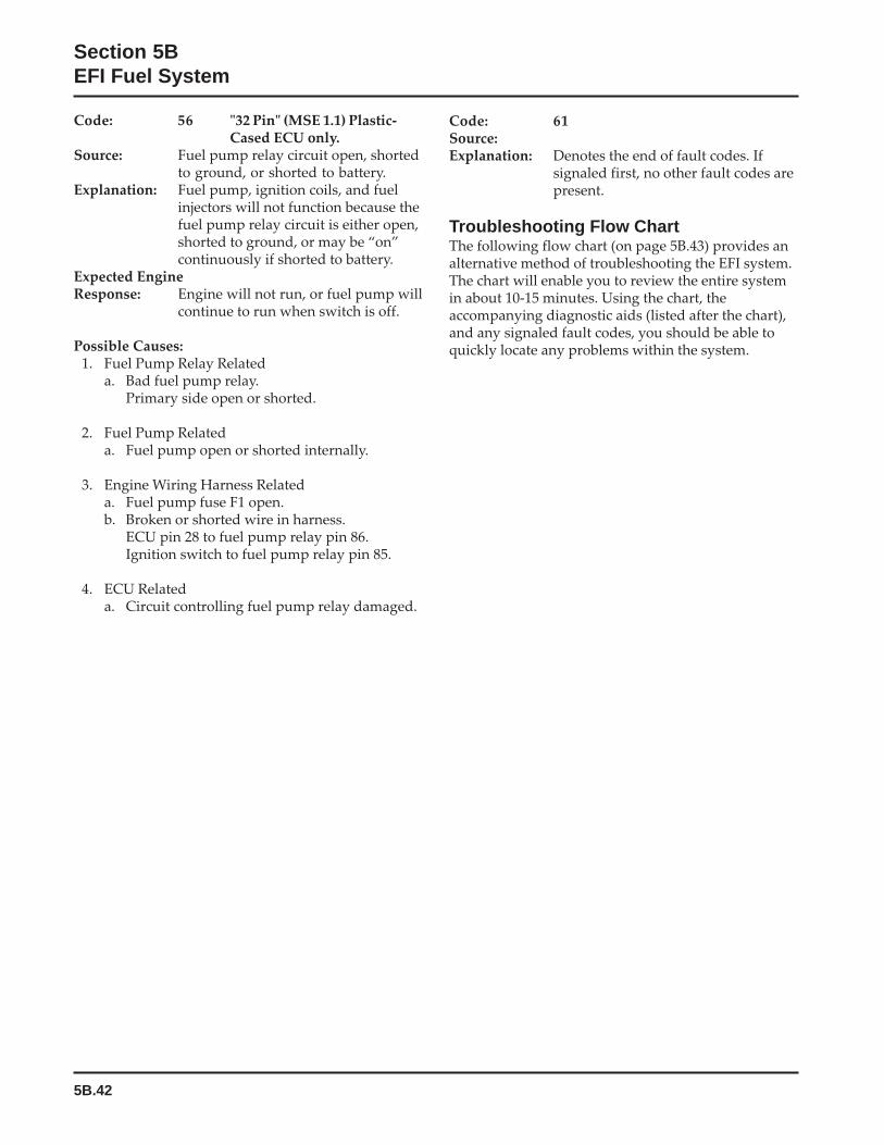
5B.42
Section 5BEFI Fuel System
Code: 56 "32 Pin" (MSE 1.1) Plastic-Cased ECU only.
Source: Fuel pump relay circuit open, shortedto ground, or shorted to battery.
Explanation: Fuel pump, ignition coils, and fuelinjectors will not function because thefuel pump relay circuit is either open,shorted to ground, or may be “on”continuously if shorted to battery.
Expected EngineResponse: Engine will not run, or fuel pump will
continue to run when switch is off.
Possible Causes:1. Fuel Pump Relay Related
a. Bad fuel pump relay.Primary side open or shorted.
2. Fuel Pump Relateda. Fuel pump open or shorted internally.
3. Engine Wiring Harness Relateda. Fuel pump fuse F1 open.b. Broken or shorted wire in harness.
ECU pin 28 to fuel pump relay pin 86.Ignition switch to fuel pump relay pin 85.
4. ECU Relateda. Circuit controlling fuel pump relay damaged.
Code: 61Source:Explanation: Denotes the end of fault codes. If
signaled first, no other fault codes arepresent.
Troubleshooting Flow ChartThe following flow chart (on page 5B.43) provides analternative method of troubleshooting the EFI system.The chart will enable you to review the entire systemin about 10-15 minutes. Using the chart, theaccompanying diagnostic aids (listed after the chart),and any signaled fault codes, you should be able toquickly locate any problems within the system.
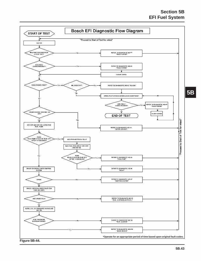
5B.43
Section 5BEFI Fuel System
5B
Figure 5B-44.*Operate for an appropriate period of time based upon original fault codes.
5B.44
Section 5BEFI Fuel System
Flow Chart Diagnostic AidsDiagnostic Aid #1 "SYSTEM POWER" (MIL does notilluminate when key is turned “on”)
Possible causes:1. Battery2. Main system fuse3. MIL light bulb burned out4. MIL electrical circuit problem
“35 Pin” (MA 1.7) Metal-Cased ECU: Pin circuits31 and 31A.“24 Pin” (MSE 1.0) Plastic-Cased ECU: Pincircuits 19 and 84.“32 Pin” (MSE 1.1) Plastic-Cased ECU: Pincircuits 29 and 84.
5. Ignition switch6. Permanent ECU power circuit problem
“35 Pin” (MA 1.7) Metal-Cased ECU: Pin circuit16.“24 Pin” (MSE 1.0) Plastic-Cased ECU: Pincircuit 1.“32 Pin” (MSE 1.1) Plastic-Cased ECU: Pincircuit 1.
7. Switched ECU power circuit problem“35 Pin” (MA 1.7) Metal-Cased ECU: Pin circuit17.“24 Pin” (MSE 1.0) Plastic-Cased ECU: Pincircuit 2.“32 Pin” (MSE 1.1) Plastic-Cased ECU: Pincircuit 2.
8 ECU grounds9. ECU
Diagnostic Aid #2 “FAULT CODES” (Refer todetailed fault code listing before flow chart and“servicing” information for the respectivecomponents)
1. Code 21 - Engine Speed Synchronization2. Code 22 - Throttle Position Sensor (TPS)3. Code 23 - Engine Control Unit (ECU)4. Code 31 - Oxygen Sensor5. Code 32 - Oxygen Sensor6. Code 33 - Fuel System (temporary adaptation
factor)7. Code 34 - Fuel System (permanent adaptation
factor)8. Code 42 - Engine (Oil) Temperature Sensor9. Code 43 - TPS “Auto-Learn” Initialization
Function (Below Min. Limit), "32 Pin" (MSE 1.1)Plastic-Cased ECU only.
10. Code 44 - TPS “Auto-Learn” InitializationFunction (Above Max. Limit), "32 Pin" (MSE 1.1)Plastic-Cased ECU only.
11. Code 51 - Injector 1, "32 Pin" (MSE 1.1) Plastic-Cased ECU only.
12. Code 52 - Injector 2, "32 Pin" (MSE 1.1) Plastic-Cased ECU only.
13. Code 55 - MIL Light, "32 Pin" (MSE 1.1) Plastic-Cased ECU only.
14. Code 56 - Pump Relay, "32 Pin" (MSE 1.1)Plastic-Cased ECU only.
15. Code 61 - End of Fault/Blink Code Transmission.
Diagnostic Aid #3 “RUN/ON” (MIL remains “on”while engine is running)*
Possible causes:1. Fault codes which turn on MIL when engine is
running.a. Code 21 - Engine Speed Synchronizationb. Code 22 - Throttle Position Sensor (TPS)c. Code 23 - Engine Control Unit (ECU)d. Code 31 - Oxygen Sensor (shorted)e. Code 34 - Fuel System (permanent adaptation
at limit)f. Code 42 - Engine (Oil) Temperature Sensorg. Code 43 - TPS “Auto-Learn” Initialization
Function (Below Min. Limit), "32 Pin"(MSE 1.1) Plastic-Cased ECU only.
h. Code 44 - TPS “Auto-Learn” InitializationFunction (Above Max. Limit) "32 Pin"(MSE 1.1) Plastic-Cased ECU only.
i. Code 51 - Injector 1, "32 Pin" (MSE 1.1)Plastic-Cased ECU only.
j. Code 52 - Injector 2, "32 Pin" (MSE 1.1)Plastic-Cased ECU only.
k. Code 55 - MIL Light, "32 Pin" (MSE 1.1)Plastic-Cased ECU only.
l. Code 56 - Pump Relay, "32 Pin" (MSE 1.1)Plastic-Cased ECU only.
2. MIL circuit grounded between light and ECU.“35 Pin” (MA 1.7) Metal-Cased ECU: Pin circuit31.“24 Pin” (MSE 1.0) Plastic-Cased ECU: Pincircuit 19.“32 Pin” (MSE 1.1) Plastic-Cased ECU: Pincircuit 29.
3. ECU
*NOTE: MIL in Metal-Cased ECU systems is an LED.The MIL in Plastic-Cased ECU systems mustbe a 1/4 watt incandescent lamp.
5B.45
Section 5BEFI Fuel System
5B
Diagnostic Aid #4 “SPEED SENSOR” (MIL does notturn off during cranking). Indicates the ECU is notreceiving a signal from the speed sensor.
Possible causes:1. Speed sensor2. Speed sensor circuit problem
“35 Pin” (MA 1.7) Metal-Cased ECU: Pin circuits3 and 21.“24 Pin” (MSE 1.0) Plastic-Cased ECU: Pincircuits 9 and 10.“32 Pin” (MSE 1.1) Plastic-Cased ECU: Pincircuits 9 and 10.
3. Speed sensor/toothed wheel air gap4. Toothed wheel5. Flywheel key sheared6. ECU
Diagnostic Aid #5 “FUEL PUMP” (fuel pump notturning on)
Possible causes:1. Fuel pump fuse2. Fuel pump circuit problem
“35 Pin” (MA 1.7) Metal-Cased ECU: Circuits 43,44, and relay.“24 Pin” (MSE 1.0) Plastic-Cased ECU: Circuits30, 87, and relay.“32 Pin” (MSE 1.1) Plastic-Cased ECU: Circuits30, 87, and relay.
3. Fuel pump
Diagnostic Aid #6 “RELAY” (relay not operating)
Possible causes:1. Safety switches/circuit(s) problem
“35 Pin” (MA 1.7) Metal-Cased ECU: Circuits 41and 41A.“24 Pin” (MSE 1.0) Plastic-Cased ECU: Circuit 3.“32 Pin” (MSE 1.1) Plastic-Cased ECU: Circuit25.
2. Relay circuit(s) problem“35 Pin” (MA 1.7) Metal-Cased ECU: Circuits 28,41, and 41A.“24 Pin” (MSE 1.0) Plastic-Cased ECU: Circuits18, 85, 30, and 87.“32 Pin” (MSE 1.1) Plastic-Cased ECU: Circuits28,85, 30, and 87.
3. Relay4. ECU grounds5. ECU
Diagnostic Aid #7 “IGNITION SYSTEM” (no spark)
Possible causes:1. Spark plug2. Plug wire3. Coil4. Coil circuit(s)
“35 Pin” (MA 1.7) Metal-Cased ECU: Circuits 1,19, 40, 40A, 43, and relay.“24 Pin” (MSE 1.0) Plastic-Cased ECU: Circuits22, 23, 65, 66, 30, and relay.“32 Pin” (MSE 1.1) Plastic-Cased ECU: Circuits30, 31, 65, 66, relay and relay circuit 30.
5. ECU grounds6. ECU
Diagnostic Aid #8 “FUEL SYSTEM-ELECTRICAL”(no fuel delivery)
Possible causes:1. No fuel2. Air in fuel rail3. Fuel valve shut off4. Fuel filter/line plugged5. Injector circuit(s)
“35 Pin” (MA 1.7) Metal-Cased ECU: Circuits 35,35A, 45, and 45A.“24 Pin” (MSE 1.0) Plastic-Cased ECU: Circuits16, 17, 45, and 45A.“32 Pin” (MSE 1.1) Plastic-Cased ECU: Circuits14,15, and 45.
6. Injector7. ECU grounds8. ECU
Diagnostic Aid #9 “FUEL SYSTEM” (fuel pressure)
Possible causes for low fuel system pressure:1. Low fuel2. Fuel filter plugged3. Fuel supply line plugged4. Pressure regulator5. Fuel pump
Possible causes for high fuel system pressure:1. Pressure regulator2. Fuel return line plugged or restricted.
Diagnostic Aid #10 “BASIC ENGINE” (cranks butwill not run)
Possible causes:1. Refer to basic engine troubleshooting charts
within service manual sections 3, 5, and 8.

6.1
Section 6Lubrication System
6
Section 6Lubrication System
GeneralThis engine uses a full pressure lubrication system.This system delivers oil under pressure to thecrankshaft, camshaft, and connecting rod bearingsurfaces. In addition to lubricating the bearingsurfaces, the lubrication system supplies oil to thehydraulic valve lifters.
A high-efficiency gerotor pump is located in theclosure plate. The oil pump maintains high oil flowand oil pressure, even at low speeds and highoperating temperatures. A pressure relief valve limitsthe maximum pressure of the system.
ServiceThe closure plate must be removed to service the oilpickup, the pressure relief valve and the oil pump.Refer to the appropriate procedures in Sections 9 and10.
Oil RecommendationsUsing the proper type and weight of oil in thecrankcase is extremely important; so is checking oildaily and changing the oil and filter regularly.
Use high-quality detergent oil of API (AmericanPetroleum Institute) service class SG, SH, SJ or higher.Select the viscosity based on the air temperature at thetime of operation as shown in the following table.
NOTE: Using other than service class SG, SH, SJ orhigher oil, or extending oil change intervalslonger than recommended can cause enginedamage.
NOTE: Synthetic oils meeting the listedclassifications may be used with oil changesperformed at the recommended intervals.However, to allow piston rings to properlyseat, a new or rebuilt engine should beoperated for at least 50 hours using standardpetroleum based oil before switching tosynthetic oil.
A logo or symbol on oil containers identifies the APIservice class and SAE viscosity grade. See Figure 6-1.
Figure 6-1. Oil Container Logo.
The top position of the symbol shows service classsuch as API SERVICE CLASS SJ. The symbol mayshow additional categories such as SH, SG/CC, orCD. The center portion shows the viscosity gradesuch as SAE 10W-30. If the bottom portion shows“Energy Conserving,” it means that oil is intended toimprove fuel economy in passenger car engines.
*
*Use of synthetic oil having 5W-20 or 5W-30 rating isacceptable, up to 4°C (40°F).**Synthetic oils will provide better starting in extremecold below -23°C (-10°F).
**

6.2
Section 6Lubrication System
NOTE: To prevent extensive engine wear or damage,always maintain the proper oil level in thecrankcase. Never operate the engine with theoil level below the ‘‘L” mark or above the ‘‘F”mark on the dipstick.
Changing Oil and Oil Filter
Changing OilChange the oil after every 100 hours of operation(more frequently under severe conditions). Refill withservice class SG, SH, SJ or higher oil as specified in the“Viscosity Grades” table on page 6.1.
Change the oil while the engine is still warm. The oilwill flow more freely and carry away moreimpurities. Make sure the engine is level when fillingor checking oil.
Change the oil as follows:1. Clean the areas around one of the oil drain plugs,
oil fill cap, and dipstick.
2. Remove one of the oil drain plugs. A drain plug islocated on either side of the crankcase; one isadjacent to and below the oil filter, the other isbelow the starter. See Figure 6-4.
Figure 6-4. Location of Oil Drains.
Checking Oil LevelThe importance of checking and maintaining theproper oil level in the crankcase cannot beoveremphasized. Check oil BEFORE EACH USE asfollows:
1. Make sure the engine is stopped, level and is coolso the oil has had time to drain into the sump.
2. Clean the area around the dipstick beforeremoving it. This will help to keep dirt, grassclippings, etc., out of the engine.
3. Remove the dipstick; wipe oil off. Reinsert thedipstick into the tube until fully seated. SeeFigure 6-2.
Figure 6-3. Oil Level Marks on Dipstick.
Oil Drain Plug Starter Side
Oil Drain Plug Oil Filter Side
DipstickOil Fill Cap (ValveCover Location)
OperatingRange
Figure 6-2. Location of Oil Fill Cap and Dipstick.
4. Remove dipstick and check oil level. The levelshould be between the ‘‘F’’ and ‘‘L’’ marks. If low,add oil of the proper type up to the "F" mark.Reinstall oil fill cap and dipstick.
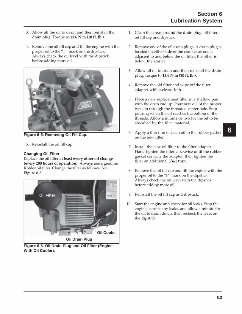
6.3
Section 6Lubrication System
6
1. Clean the areas around the drain plug, oil filter,oil fill cap and dipstick.
2. Remove one of the oil drain plugs. A drain plug islocated on either side of the crankcase; one isadjacent to and below the oil filter, the other isbelow the starter.
3. Allow all oil to drain and then reinstall the drainplug. Torque to 13.6 N·m (10 ft. lb.).
4. Remove the old filter and wipe off the filteradapter with a clean cloth.
5. Place a new replacement filter in a shallow panwith the open end up. Pour new oil, of the propertype, in through the threaded center hole. Stoppouring when the oil reaches the bottom of thethreads. Allow a minute or two for the oil to beabsorbed by the filter material.
6. Apply a thin film of clean oil to the rubber gasketon the new filter.
7. Install the new oil filter to the filter adapter.Hand tighten the filter clockwise until the rubbergasket contacts the adapter, then tighten thefilter an additional 3/4-1 turn.
8. Remove the oil fill cap and fill the engine with theproper oil to the ‘‘F’’ mark on the dipstick.Always check the oil level with the dipstickbefore adding more oil.
9. Reinstall the oil fill cap and dipstick.
10. Start the engine and check for oil leaks. Stop theengine, correct any leaks, and allow a minute forthe oil to drain down, then recheck the level onthe dipstick.
Figure 6-5. Removing Oil Fill Cap.
5. Reinstall the oil fill cap.
Changing Oil FilterReplace the oil filter at least every other oil change(every 200 hours of operation). Always use a genuineKohler oil filter. Change the filter as follows. SeeFigure 6-6.
Figure 6-6. Oil Drain Plug and Oil Filter (EngineWith Oil Cooler).
Oil Filter
Oil Cooler
Oil Drain Plug
3. Allow all the oil to drain and then reinstall thedrain plug. Torque to 13.6 N·m (10 ft. lb.).
4. Remove the oil fill cap and fill the engine with theproper oil to the ‘‘F’’ mark on the dipstick.Always check the oil level with the dipstickbefore adding more oil.
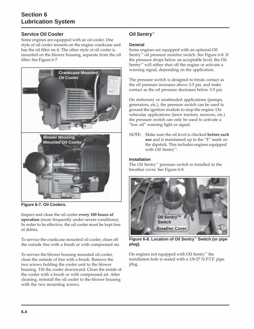
6.4
Section 6Lubrication System
Figure 6-7. Oil Coolers.
Inspect and clean the oil cooler every 100 hours ofoperation (more frequently under severe conditions).In order to be effective, the oil cooler must be kept freeof debris.
To service the crankcase mounted oil cooler, clean offthe outside fins with a brush or with compressed air.
To service the blower housing mounted oil cooler,clean the outside of fins with a brush. Remove thetwo screws holding the cooler unit to the blowerhousing. Tilt the cooler downward. Clean the inside ofthe cooler with a brush or with compressed air. Aftercleaning, reinstall the oil cooler to the blower housingwith the two mounting screws.
Oil Sentry™
GeneralSome engines are equipped with an optional OilSentry™ oil pressure monitor switch. See Figure 6-8. Ifthe pressure drops below an acceptable level, the OilSentry™ will either shut off the engine or activate awarning signal, depending on the application.
The pressure switch is designed to break contact asthe oil pressure increases above 3-5 psi, and makecontact as the oil pressure decreases below 3-5 psi.
On stationary or unattended applications (pumps,generators, etc.), the pressure switch can be used toground the ignition module to stop the engine. Onvehicular applications (lawn tractors, mowers, etc.)the pressure switch can only be used to activate a“low oil” warning light or signal.
NOTE: Make sure the oil level is checked before eachuse and is maintained up to the “F” mark onthe dipstick. This includes engines equippedwith Oil Sentry™.
InstallationThe Oil Sentry™ pressure switch is installed in thebreather cover. See Figure 6-8.
Service Oil CoolerSome engines are equipped with an oil cooler. Onestyle of oil cooler mounts on the engine crankcase andhas the oil filter on it. The other style of oil cooler ismounted on the blower housing, separate from the oilfilter. See Figure 6-7.
Blower HousingMounted Oil Cooler
Crankcase MountedOil Cooler
Figure 6-8. Location of Oil Sentry™ Switch (or pipeplug).
On engines not equipped with Oil Sentry™ theinstallation hole is sealed with a 1/8-27 N.P.T.F. pipeplug.
Breather Cover
Oil Sentry™Switch
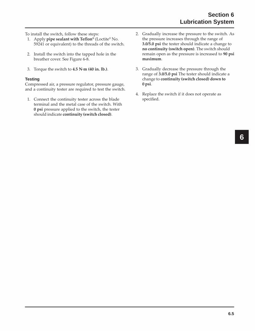
6.5
Section 6Lubrication System
6
To install the switch, follow these steps:1. Apply pipe sealant with Teflon® (Loctite® No.
59241 or equivalent) to the threads of the switch.
2. Install the switch into the tapped hole in thebreather cover. See Figure 6-8.
3. Torque the switch to 4.5 N·m (40 in. lb.).
TestingCompressed air, a pressure regulator, pressure gauge,and a continuity tester are required to test the switch.
1. Connect the continuity tester across the bladeterminal and the metal case of the switch. With0 psi pressure applied to the switch, the testershould indicate continuity (switch closed).
2. Gradually increase the pressure to the switch. Asthe pressure increases through the range of3.0/5.0 psi the tester should indicate a change tono continuity (switch open). The switch shouldremain open as the pressure is increased to 90 psimaximum.
3. Gradually decrease the pressure through therange of 3.0/5.0 psi The tester should indicate achange to continuity (switch closed) down to0 psi.
4. Replace the switch if it does not operate asspecified.
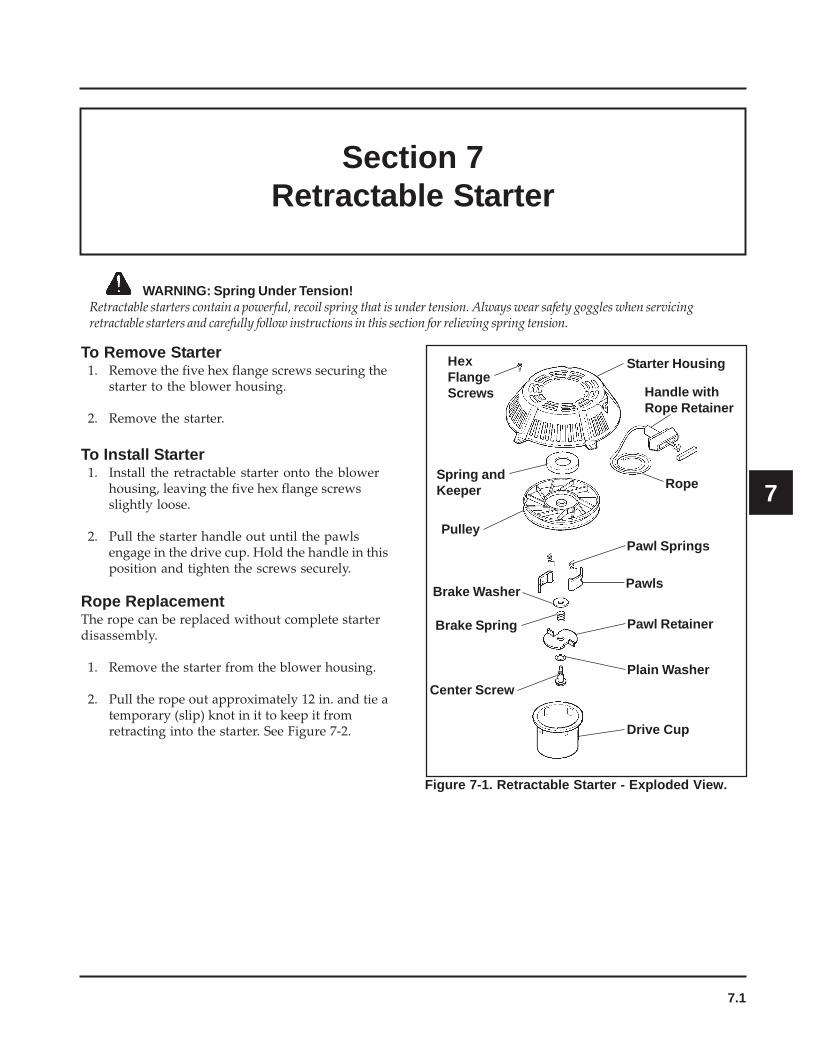
7.1
7
Section 7Retractable Starter
WARNING: Spring Under Tension!Retractable starters contain a powerful, recoil spring that is under tension. Always wear safety goggles when servicingretractable starters and carefully follow instructions in this section for relieving spring tension.
To Remove Starter1. Remove the five hex flange screws securing the
starter to the blower housing.
2. Remove the starter.
To Install Starter1. Install the retractable starter onto the blower
housing, leaving the five hex flange screwsslightly loose.
2. Pull the starter handle out until the pawlsengage in the drive cup. Hold the handle in thisposition and tighten the screws securely.
Rope ReplacementThe rope can be replaced without complete starterdisassembly.
1. Remove the starter from the blower housing.
2. Pull the rope out approximately 12 in. and tie atemporary (slip) knot in it to keep it fromretracting into the starter. See Figure 7-2.
Handle withRope Retainer
Drive Cup
Starter Housing
Rope
Pawl Springs
Pawls
Pawl Retainer
Plain Washer
Center Screw
Brake Spring
Brake Washer
Pulley
Spring andKeeper
HexFlangeScrews
Figure 7-1. Retractable Starter - Exploded View.
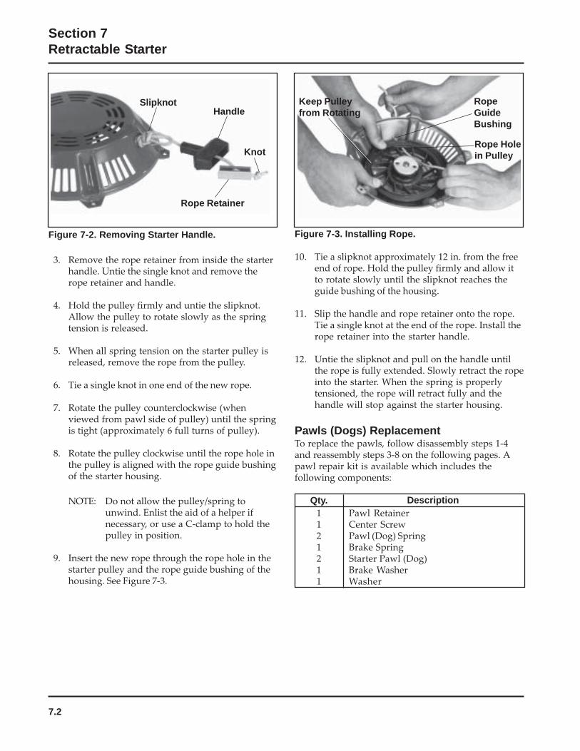
7.2
Section 7Retractable Starter
Figure 7-3. Installing Rope.
10. Tie a slipknot approximately 12 in. from the freeend of rope. Hold the pulley firmly and allow itto rotate slowly until the slipknot reaches theguide bushing of the housing.
11. Slip the handle and rope retainer onto the rope.Tie a single knot at the end of the rope. Install therope retainer into the starter handle.
12. Untie the slipknot and pull on the handle untilthe rope is fully extended. Slowly retract the ropeinto the starter. When the spring is properlytensioned, the rope will retract fully and thehandle will stop against the starter housing.
Pawls (Dogs) ReplacementTo replace the pawls, follow disassembly steps 1-4and reassembly steps 3-8 on the following pages. Apawl repair kit is available which includes thefollowing components:
Figure 7-2. Removing Starter Handle.
3. Remove the rope retainer from inside the starterhandle. Untie the single knot and remove therope retainer and handle.
4. Hold the pulley firmly and untie the slipknot.Allow the pulley to rotate slowly as the springtension is released.
5. When all spring tension on the starter pulley isreleased, remove the rope from the pulley.
6. Tie a single knot in one end of the new rope.
7. Rotate the pulley counterclockwise (whenviewed from pawl side of pulley) until the springis tight (approximately 6 full turns of pulley).
8. Rotate the pulley clockwise until the rope hole inthe pulley is aligned with the rope guide bushingof the starter housing.
NOTE: Do not allow the pulley/spring tounwind. Enlist the aid of a helper ifnecessary, or use a C-clamp to hold thepulley in position.
9. Insert the new rope through the rope hole in thestarter pulley and the rope guide bushing of thehousing. See Figure 7-3.
Keep Pulleyfrom Rotating
RopeGuideBushing
Rope Holein Pulley
DescriptionQty.Pawl RetainerCenter ScrewPawl (Dog) SpringBrake SpringStarter Pawl (Dog)Brake WasherWasher
1121211
SlipknotHandle
Knot
Rope Retainer
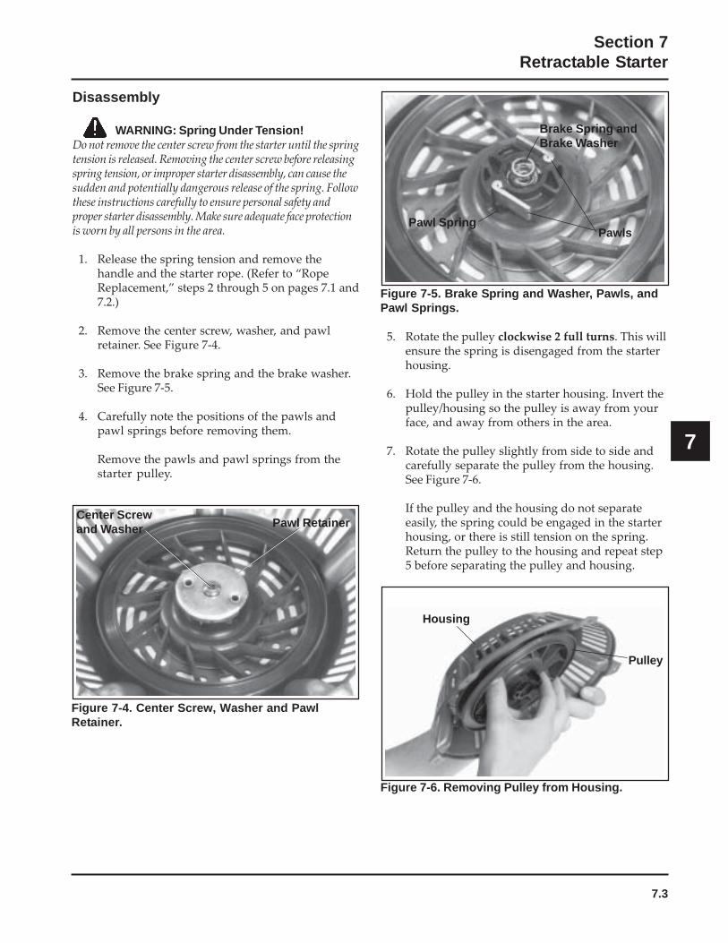
7.3
Section 7Retractable Starter
7
Disassembly
WARNING: Spring Under Tension!Do not remove the center screw from the starter until the springtension is released. Removing the center screw before releasingspring tension, or improper starter disassembly, can cause thesudden and potentially dangerous release of the spring. Followthese instructions carefully to ensure personal safety andproper starter disassembly. Make sure adequate face protectionis worn by all persons in the area.
1. Release the spring tension and remove thehandle and the starter rope. (Refer to “RopeReplacement,” steps 2 through 5 on pages 7.1 and7.2.)
2. Remove the center screw, washer, and pawlretainer. See Figure 7-4.
3. Remove the brake spring and the brake washer.See Figure 7-5.
4. Carefully note the positions of the pawls andpawl springs before removing them.
Remove the pawls and pawl springs from thestarter pulley.
Figure 7-5. Brake Spring and Washer, Pawls, andPawl Springs.
5. Rotate the pulley clockwise 2 full turns. This willensure the spring is disengaged from the starterhousing.
6. Hold the pulley in the starter housing. Invert thepulley/housing so the pulley is away from yourface, and away from others in the area.
7. Rotate the pulley slightly from side to side andcarefully separate the pulley from the housing.See Figure 7-6.
If the pulley and the housing do not separateeasily, the spring could be engaged in the starterhousing, or there is still tension on the spring.Return the pulley to the housing and repeat step5 before separating the pulley and housing.
Center Screwand Washer Pawl Retainer
Housing
Pulley
Brake Spring andBrake Washer
PawlsPawl Spring
Figure 7-4. Center Screw, Washer and PawlRetainer.
Figure 7-6. Removing Pulley from Housing.
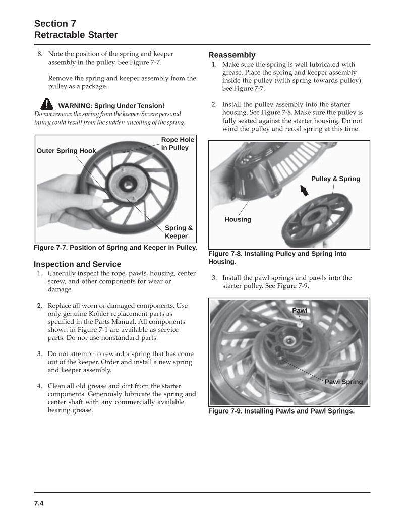
7.4
Section 7Retractable Starter
8. Note the position of the spring and keeperassembly in the pulley. See Figure 7-7.
Remove the spring and keeper assembly from thepulley as a package.
Rope Holein PulleyOuter Spring Hook
Spring &Keeper
Figure 7-7. Position of Spring and Keeper in Pulley.
Inspection and Service1. Carefully inspect the rope, pawls, housing, center
screw, and other components for wear ordamage.
2. Replace all worn or damaged components. Useonly genuine Kohler replacement parts asspecified in the Parts Manual. All componentsshown in Figure 7-1 are available as serviceparts. Do not use nonstandard parts.
3. Do not attempt to rewind a spring that has comeout of the keeper. Order and install a new springand keeper assembly.
4. Clean all old grease and dirt from the startercomponents. Generously lubricate the spring andcenter shaft with any commercially availablebearing grease.
Reassembly1. Make sure the spring is well lubricated with
grease. Place the spring and keeper assemblyinside the pulley (with spring towards pulley).See Figure 7-7.
2. Install the pulley assembly into the starterhousing. See Figure 7-8. Make sure the pulley isfully seated against the starter housing. Do notwind the pulley and recoil spring at this time.
Pulley & Spring
Housing
Figure 7-8. Installing Pulley and Spring intoHousing.
3. Install the pawl springs and pawls into thestarter pulley. See Figure 7-9.
Pawl
Pawl Spring
Figure 7-9. Installing Pawls and Pawl Springs.
WARNING: Spring Under Tension!Do not remove the spring from the keeper. Severe personalinjury could result from the sudden uncoiling of the spring.
7.5
Section 7Retractable Starter
7
4. Place the brake washer in the recess in starterpulley; over the center shaft.
5. Lubricate the brake spring sparingly withgrease. Place the spring on the plain washer.Make sure the threads in the center shaft remainclean, dry, and free of grease and oil.
6. Apply a small amount of Loctite® No. 271 to thethreads of the center screw. Install the centerscrew with the washer and retainer to thecenter shaft. Torque the screw to 7.4-8.5 N·m(65-75 in. lb.).
7. Tension the spring and install the rope andhandle as instructed in steps 6 through 12 under“Rope Replacement” on page 7.2.
8. Install the starter to the engine blower housingas instructed in “To Install Starter” on page 7.1.

8.1
Section 8Electrical System and Components
8
Section 8Electrical System and Components
This section covers the operation, service, and repairof the electrical system components. Systems andcomponents covered in this section are:
• Spark Plugs• Battery and Charging System• Electronic CD Ignition System (including SMART-
SPARK™
on applicable models)• Electric Starter
Spark PlugsEngine misfire or starting problems are often causedby a spark plug that has improper gap or is in poorcondition.
The engine is equipped with the following sparkplugs:
Type: The standard spark plug is a Champion®
RC12YC (Kohler Part No. 12 132 02-S). RFIcompliant engines use a Champion® XC12YC(Kohler 25 132 14-S) spark plug. A high-performance spark plug, Champion® Platinum3071 (used on Pro Series engines, Kohler PartNo. 25 132 12-S) is also available. Equivalentalternate brand plugs can also be used.
Gap: 0.76 mm (0.030 in.)Thread Size: 14 mmReach: 19.1 mm (3/4 in.)Hex Size: 15.9 mm (5/8 in.)
Spark Plug ServiceEvery 200 hours of operation, remove each spark plug.Check its condition and either reset the gap or replacewith a new plug as necessary. To service the plugs,perform the following steps:
1. Before removing each spark plug, clean the areaaround the base of the plug to keep dirt anddebris out of the engine.
2. Remove the plug and check its condition. See“Inspection” following this procedure. Replacethe plug if necessary.
NOTE: Do not clean spark plug in a machineusing abrasive grit. Some grit couldremain in the spark plug and enter theengine causing extensive wear anddamage.
3. Check the gap using a wire feeler gauge. Adjustthe gap to 0.76 mm (0.030 in.) by carefullybending the ground electrode. See Figure 8-1.
Figure 8-1. Servicing Spark Plug.
4. Reinstall the spark plug into the cylinder headand torque to 24.4-29.8 N·m (18-22 ft. lb.).
InspectionInspect each spark plug as it is removed from thecylinder head. The deposits on the tip are anindication of the general condition of the piston rings,valves, and carburetor.
Normal and fouled plugs are shown in the followingphotos:
Wire Gauge
GroundElectrode
Spark Plug
0.76 mm (0.030 in.) Gap
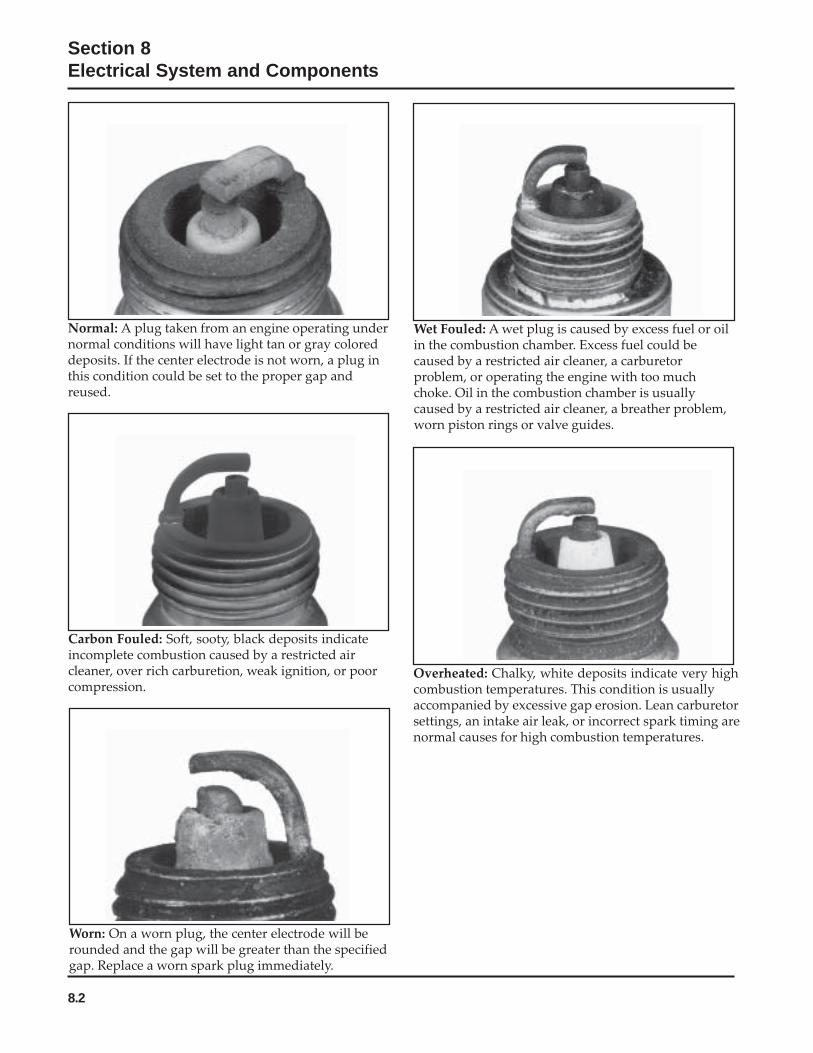
8.2
Section 8Electrical System and Components
Normal: A plug taken from an engine operating undernormal conditions will have light tan or gray coloreddeposits. If the center electrode is not worn, a plug inthis condition could be set to the proper gap andreused.
Wet Fouled: A wet plug is caused by excess fuel or oilin the combustion chamber. Excess fuel could becaused by a restricted air cleaner, a carburetorproblem, or operating the engine with too muchchoke. Oil in the combustion chamber is usuallycaused by a restricted air cleaner, a breather problem,worn piston rings or valve guides.
Carbon Fouled: Soft, sooty, black deposits indicateincomplete combustion caused by a restricted aircleaner, over rich carburetion, weak ignition, or poorcompression.
Worn: On a worn plug, the center electrode will berounded and the gap will be greater than the specifiedgap. Replace a worn spark plug immediately.
Overheated: Chalky, white deposits indicate very highcombustion temperatures. This condition is usuallyaccompanied by excessive gap erosion. Lean carburetorsettings, an intake air leak, or incorrect spark timing arenormal causes for high combustion temperatures.
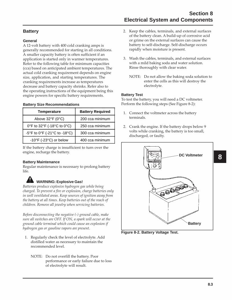
8.3
Section 8Electrical System and Components
8
2. Keep the cables, terminals, and external surfacesof the battery clean. A build-up of corrosive acidor grime on the external surfaces can cause thebattery to self-discharge. Self-discharge occursrapidly when moisture is present.
3. Wash the cables, terminals, and external surfaceswith a mild baking soda and water solution.Rinse thoroughly with clear water.
NOTE: Do not allow the baking soda solution toenter the cells as this will destroy theelectrolyte.
Battery TestTo test the battery, you will need a DC voltmeter.Perform the following steps (See Figure 8-2):
1. Connect the voltmeter across the batteryterminals.
2. Crank the engine. If the battery drops below 9volts while cranking, the battery is too small,discharged, or faulty.
Battery
GeneralA 12-volt battery with 400 cold cranking amps isgenerally recommended for starting in all conditions.A smaller capacity battery is often sufficient if anapplication is started only in warmer temperatures.Refer to the following table for minimum capacities(cca) based on anticipated ambient temperatures. Theactual cold cranking requirement depends on enginesize, application, and starting temperatures. Thecranking requirements increase as temperaturesdecrease and battery capacity shrinks. Refer also tothe operating instructions of the equipment being thisengine powers for specific battery requirements.
Battery Size Recommendations
If the battery charge is insufficient to turn over theengine, recharge the battery.
Battery MaintenanceRegular maintenance is necessary to prolong batterylife.
Figure 8-2. Battery Voltage Test.
DC Voltmeter
Battery
Temperature Battery Required
Above 32°F (0°C) 200 cca minimum
0°F to 32°F (-18°C to 0°C) 250 cca minimum
-5°F to 0°F (-21°C to -18°C) 300 cca minimum
-10°F (-23°C) or below 400 cca minimum
WARNING: Explosive Gas!Batteries produce explosive hydrogen gas while beingcharged. To prevent a fire or explosion, charge batteries onlyin well ventilated areas. Keep sources of ignition away fromthe battery at all times. Keep batteries out of the reach ofchildren. Remove all jewelry when servicing batteries.
Before disconnecting the negative (-) ground cable, makesure all switches are OFF. If ON, a spark will occur at theground cable terminal which could cause an explosion ifhydrogen gas or gasoline vapors are present.
1. Regularly check the level of electrolyte. Adddistilled water as necessary to maintain therecommended level.
NOTE: Do not overfill the battery. Poorperformance or early failure due to lossof electrolyte will result.

8.4
Section 8Electrical System and Components
The SMART-SPARK™
ignition system used on somemodels is an advanced version of the CD ignitionsystem used on other CH engines. Its operation can bebest understood by first understanding the standardsystem and how it works. Since both systems willcontinue in use, it is advantageous to understand themboth. The operation of the standard system isexplained first then expanded to cover SMART-
SPARK™
.
Electronic CD Ignition Systems
Figure 8-3. Electronic CD Ignition System (For Customer Connected Tractor Applications).
Operation of CD Ignition Systems
A. Capacitive Discharge with Fixed TimingThis system (Figure 8-3) consists of the followingcomponents:
• A magnet assembly which is permanently affixedto the flywheel.
• Two electronic capacitive-discharge ignitionmodules which mount on the engine crankcase(Figure 8-4).
• A kill switch (or key switch) which grounds themodules to stop the engine.
• Two spark plugs.
Oil PressureSafety Input
Rectifier-Regulator
B+ andCarburetorSolenoidInput
IgnitionModuleInput
CarburetorSolenoid
OilPressureSafety
Red
Green
White
IgnitionModules
SparkPlugs
B+Violet
Red
Starter andCarburetorSolenoidInput
White
Red
RedSparkAdvanceModule(Optional)
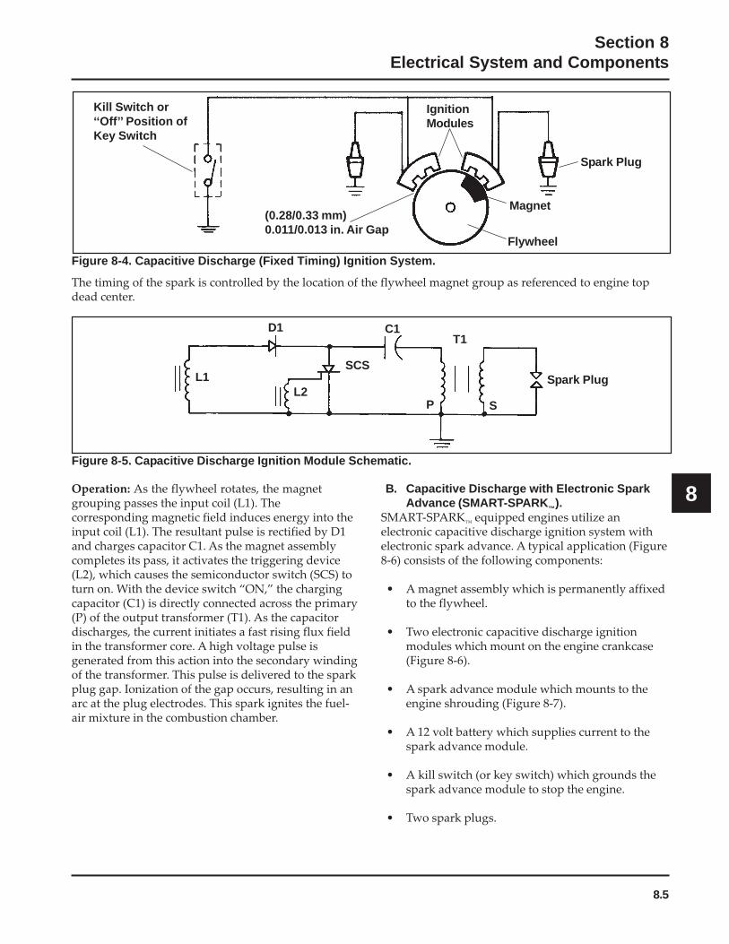
8.5
Section 8Electrical System and Components
8
Figure 8-4. Capacitive Discharge (Fixed Timing) Ignition System.
Kill Switch or‘‘Off’’ Position ofKey Switch
IgnitionModules
Spark Plug
Magnet
Flywheel
(0.28/0.33 mm)0.011/0.013 in. Air Gap
L1
D1 C1T1
P S
Spark PlugL2
SCS
Figure 8-5. Capacitive Discharge Ignition Module Schematic.
The timing of the spark is controlled by the location of the flywheel magnet group as referenced to engine topdead center.
B. Capacitive Discharge with Electronic SparkAdvance (SMART-SPARK™).
SMART-SPARK™
equipped engines utilize anelectronic capacitive discharge ignition system withelectronic spark advance. A typical application (Figure8-6) consists of the following components:
• A magnet assembly which is permanently affixedto the flywheel.
• Two electronic capacitive discharge ignitionmodules which mount on the engine crankcase(Figure 8-6).
• A spark advance module which mounts to theengine shrouding (Figure 8-7).
• A 12 volt battery which supplies current to thespark advance module.
• A kill switch (or key switch) which grounds thespark advance module to stop the engine.
• Two spark plugs.
Operation: As the flywheel rotates, the magnetgrouping passes the input coil (L1). Thecorresponding magnetic field induces energy into theinput coil (L1). The resultant pulse is rectified by D1and charges capacitor C1. As the magnet assemblycompletes its pass, it activates the triggering device(L2), which causes the semiconductor switch (SCS) toturn on. With the device switch “ON,” the chargingcapacitor (C1) is directly connected across the primary(P) of the output transformer (T1). As the capacitordischarges, the current initiates a fast rising flux fieldin the transformer core. A high voltage pulse isgenerated from this action into the secondary windingof the transformer. This pulse is delivered to the sparkplug gap. Ionization of the gap occurs, resulting in anarc at the plug electrodes. This spark ignites the fuel-air mixture in the combustion chamber.

8.6
Section 8Electrical System and Components
Figure 8-6. Capacitive Discharge Ignition System with Spark Advance.
Figure 8-7. Block Diagram - Spark Advance Module.
Operation: The ignition module for this system operates in the same fashion as the fixed timing module, exceptthe trigger circuit for the semiconductor (L2, Figure 8-5) is replaced by the spark advance module (Figure 8-7).
The timing of the spark is controlled by the location of the flywheel magnet group as referenced to the engine topdead center and the delay created by the spark advance module.
PowerSource
PulseGenerator
ResetCircuit
B+ (12 VDC)Red
Yellow ToSemi-ConductorSwitch
Comparator
DelayCircuit
ChargePump
ConditioningCircuit
V+ (7.2V)
BrownFromInputCoil
Gre
eno
r B
lack
SparkPlug
Key Switch or ‘‘Off’’Position of Key Switch Spark
AdvanceModule
12 Volt Battery
IgnitionModule
Flywheel Magnet
0.28/0.33 mm(0.011/0.013 in.) Air Gap
SparkPlug
Green
Red
White
8.7
Section 8Electrical System and Components
8
The pulse generated by the input coil of the ignitionmodule (L1, Figure 8-5) is fed to the input of theconditioning circuit. The conditioning circuit shapesthis pulse, putting it in a useable form for theadditional circuits. This pulse starts the charge pump,which charges a capacitor in a linear fashion that canbe directly related to the engine speed. At the sametime the pulse resets the delay circuit for length of thepulse width. The comparator is off during this periodand no output is generated. As soon as the originalpulse drops back to zero, the capacitor in the delaycircuit begins to charge.
When the charge on the delay capacitor exceeds thecharge on the charge pump capacitor the comparatorchanges state, activating the pulse generator. Thispulse turns “ON” the CD ignition modulesemiconductor. Energy is then transferred to thesecondary of the output transformer (T1, Figure 8-5).The high voltage pulse generated here is delivered tothe spark plug, causing arcing of the spark gap andigniting the fuel-air mixture in the combustionchamber. As the trigger pulse is generated, allassociated circuits are reset, their capacitorsdischarged. The longer it takes the delay circuit tosurpass the charge pump capacitor voltage, the laterthe trigger pulse will occur, retarding the timingaccordingly.
Troubleshooting CD Ignition SystemsThe CD ignition systems are designed to be troublefree for the life of the engine. Other than periodicallychecking/replacing the spark plugs, no maintenance ortiming adjustments are necessary or possible.Mechanical systems do occasionally fail or breakdown however, so the following troubleshootinginformation is provided to help you get to the root ofa reported problem.
CAUTION: High-Energy Electric Spark!The CD ignition systems produce a high-energy electricspark, but the spark must be discharged, or damage to thesystem can result. Do not crank or run an engine with aspark plug lead disconnected. Always provide a path for thespark to discharge to ground.
Reported ignition problems are most often due topoor connections. Before beginning the test procedure,check all external wiring. Be certain all ignition-related wires are connected, including the spark plugleads. Be certain all terminal connections fit snugly.Make sure the ignition switch is in the run position.
NOTE: The CD ignition systems are sensitive toexcessive load on the kill lead. If a customercomplains of hard starting, low power, ormisfire under load, it may be due to excessivedraw on the kill circuit. Perform theappropriate test procedure.
Test Procedure for Standard (Fixed Timing) CDIgnition SystemIsolate and verify the trouble is within the engineignition system.
1. Locate the plug connectors where the wiringharnesses from the engine and equipment arejoined. Separate the connectors and remove thewhite “kill” lead from the engine connector. Rejointhe connectors and position or insulate the kill leadterminal so it cannot touch ground. Try to start**the engine to verify whether the reported problemis still present.
a. If the problem is gone, the electricalsystem on the unit is suspect. Check the keyswitch, wires, connections, safety interlocks,etc.
b. If the problem persists the condition isassociated with the ignition or electricalsystem of the engine. Leave the kill leadisolated until all testing is completed.
**NOTE: If the engine starts or runs during any of thetesting, you may need to ground the kill leadto shut it down. Because you haveinterrupted the kill circuit, it may not stopusing the switch.
2. Test for spark on both cylinders with Kohlerignition tester (see Section 2). Disconnect one sparkplug lead and connect it to the post terminal of thetester. Connect the clip to a good ground, not tothe spark plug. Crank the engine and observe thetester spark gap. Repeat the procedure on theother cylinder. Remember to reconnect the firstspark plug lead.
a. If one side is not firing, check all wiring,connections, and terminations on that side. Ifwiring is okay, replace ignition module andretest for spark.
b. If the tester shows spark, but the enginemisses or won’t run on that cylinder, try a newspark plug.

8.8
Section 8Electrical System and Components
c. If neither side is firing, recheck position ofignition switch and check for shorted kill lead.
Test Procedure for SMART-SPARKTM IgnitionSystemsThe following procedures are provided fortroubleshooting ignition problems on SMART-SPARK
™equipped engines. They will allow you to
isolate and pinpoint the failed component(s).
Special Tools Required:• Hand Tachometer• Tester* (see Section 2)• Automotive timing light• Multi-meter (digital)
Specifications Required:• Spark plug gap 0.76 mm (0.030 in.)• Ignition module air gap 0.28/0.33 mm
(0.011-0.013 in.), 0.30 mm (0.012 in.) nominal
*NOTE: Ignition tester (see Section 2) must be used totest ignition on these engines. Use of anyother tester can result in inaccurate findings.Battery on unit must be fully charged andproperly connected before making any ofthese tests (a battery that is hooked up orcharged backward will crank the engine, butit won’t have spark). Be sure drive is inneutral and all external loads aredisconnected.
Test 1. Isolate and verify the trouble is within theengine ignition system.
1. Locate the plug connectors where the wiringharnesses from the engine and equipment arejoined. Separate the connectors and remove thewhite “kill” lead from the engine connector.Rejoin the connectors and position or insulate thekill lead terminal so it cannot touch ground. Tryto start** the engine to verify whether thereported problem is still present.
a. If the problem is gone, the electrical system onthe unit is suspect. Check the key switch,wires, connections, safety interlocks, etc.
b. If the problem persists the condition isassociated with the ignition or electricalsystem of the engine. Leave the kill leadisolated until all testing is completed.
**NOTE: If the engine starts or runs during any of thetesting, you may need to ground the kill leadto shut it down. Because you haveinterrupted the kill circuit, it may not stopusing the switch.
Test 2. Test for spark.1. With the engine stopped, disconnect one spark
plug lead. Connect the spark plug lead to postterminal of spark tester (see Section 2), andattach tester clip to a good engine ground.
NOTE: If two testers are available, testing can beperformed simultaneously for both cylinders.However, if only one tester is available, twoindividual tests must be performed. The sidenot being tested must have the spark pluglead connected or grounded. Do not crankthe engine or perform tests with one sparkplug lead disconnected and not grounded orpermanent system damage may occur.
2. Crank the engine over, establishing a minimum of550-600 RPM, and observe tester(s) for spark.
3. On a twin cylinder engine, repeat the spark teston the opposite cylinder if cylinders are beingtested individually.
a. If both cylinders have good spark, but theengine runs poorly, install new spark plugsgapped at 0.76 mm (0.030 in.), and retestengine performance. If problem persists, goto Test 3.
b. If one cylinder had good spark, but theother cylinder had no spark or intermittentspark, go to Test 3.
c. If there was no spark or intermittent sparkon both cylinders, go to Test 4.

8.9
Section 8Electrical System and Components
8
Figure 8-9.
3. Run the engine at idle and use the timing lightbeam to locate the line on the screen. Draw a lineon the blower housing adjacent to the line on thescreen. Accelerate to full throttle and watch formovement of the line on the screen relative to theline on the blower housing. If both cylinders hadgood spark, repeat the test on the other cylinder.
a. If the line on the screen moved away fromthe line on the blower housing duringacceleration, the SAM is working properly. Ifit didn’t move away, go to Test 5.
b. If you were able to check timing on bothcylinders, the lines you made on the blowerhousing should be 90° apart. If they’re not,go to Test 4.
Test 4. Test the ignition modules and connections.1. Remove the blower housing from the engine.
Inspect the wiring for any damage, cuts, badcrimps, loose terminals, or broken wires.
2. Disconnect the leads from the ignition module(s)and clean all of the terminals (male and female)with aerosol electrical contact cleaner to removeany old dielectric compound, dark residue, dirt,or contamination. Disconnect the spark plug leadsfrom the spark plugs.
3. Remove one of the mounting screws from each ofthe ignition modules. If the mounting screws areblack, remove them both and discard. Replacethem with part number M-561025-S. Look in themounting hole with a flashlight and use a smallround wire brush to remove any loose rust fromthe laminations inside the mounting hole.
4. Refer to the chart on page 8.10 to identify whichignition module(s) you have. If they are thesmaller style, check the vendor part number onthe face. All modules with vendor part numbersMA-2, MA-2A, or MA-2B (Kohler Part No.24 584 03) should be replaced with 24 584 11 or24 584 15-S. For small modules with vendornumbers MA-2C or MA-2D (Kohler Part No.24 584 11), or the larger style modules (24 584 15-Sand 24 584 36-S), use a digital ohmmeter to checkthe resistance values and compare them to thetable following. When testing resistance to thelaminations, touch the probe to the laminationsinside the screw hole, as some laminations have arust preventative coating on the surface whichcould alter the resistance reading.
a. If all of the resistance values are within theranges specified in the table, go to step 5.
b. If any of the resistance values are not withinthe ranges specified in the table,# thatmodule is faulty and must be replaced.
#NOTE: The resistance values apply only tomodules that have been on a runningengine. New service modules may havehigher resistance until they have beenrun.
Test 3. Check for timing advance.
Figure 8-8.
1. Make a line near the edge of the flywheel screenwith a marking pen or narrow tape.
2. Connect an automotive timing light to cylinderthat had good spark.
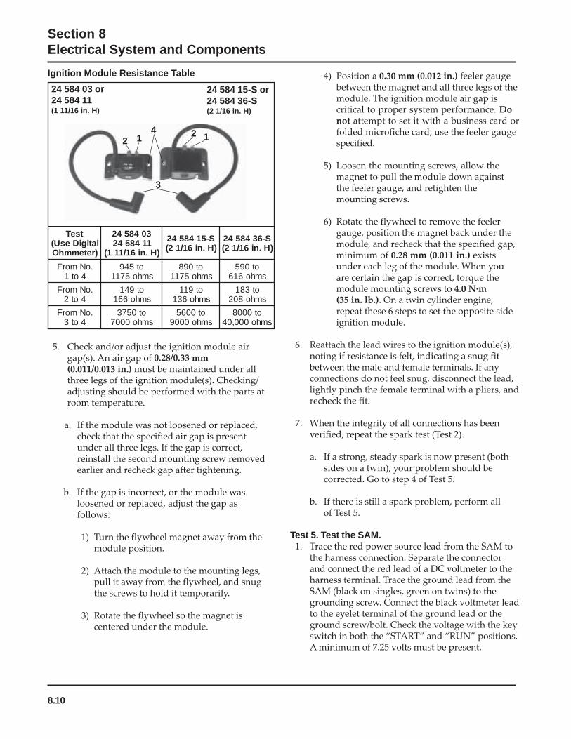
8.10
Section 8Electrical System and Components
5. Check and/or adjust the ignition module airgap(s). An air gap of 0.28/0.33 mm(0.011/0.013 in.) must be maintained under allthree legs of the ignition module(s). Checking/adjusting should be performed with the parts atroom temperature.
a. If the module was not loosened or replaced,check that the specified air gap is presentunder all three legs. If the gap is correct,reinstall the second mounting screw removedearlier and recheck gap after tightening.
b. If the gap is incorrect, or the module wasloosened or replaced, adjust the gap asfollows:
1) Turn the flywheel magnet away from themodule position.
2) Attach the module to the mounting legs,pull it away from the flywheel, and snugthe screws to hold it temporarily.
3) Rotate the flywheel so the magnet iscentered under the module.
4) Position a 0.30 mm (0.012 in.) feeler gaugebetween the magnet and all three legs of themodule. The ignition module air gap iscritical to proper system performance. Donot attempt to set it with a business card orfolded microfiche card, use the feeler gaugespecified.
5) Loosen the mounting screws, allow themagnet to pull the module down againstthe feeler gauge, and retighten themounting screws.
6) Rotate the flywheel to remove the feelergauge, position the magnet back under themodule, and recheck that the specified gap,minimum of 0.28 mm (0.011 in.) existsunder each leg of the module. When youare certain the gap is correct, torque themodule mounting screws to 4.0 N·m(35 in. lb.). On a twin cylinder engine,repeat these 6 steps to set the opposite sideignition module.
6. Reattach the lead wires to the ignition module(s),noting if resistance is felt, indicating a snug fitbetween the male and female terminals. If anyconnections do not feel snug, disconnect the lead,lightly pinch the female terminal with a pliers, andrecheck the fit.
7. When the integrity of all connections has beenverified, repeat the spark test (Test 2).
a. If a strong, steady spark is now present (bothsides on a twin), your problem should becorrected. Go to step 4 of Test 5.
b. If there is still a spark problem, perform allof Test 5.
Test 5. Test the SAM.1. Trace the red power source lead from the SAM to
the harness connection. Separate the connectorand connect the red lead of a DC voltmeter to theharness terminal. Trace the ground lead from theSAM (black on singles, green on twins) to thegrounding screw. Connect the black voltmeter leadto the eyelet terminal of the ground lead or theground screw/bolt. Check the voltage with the keyswitch in both the “START” and “RUN” positions.A minimum of 7.25 volts must be present.
2 14 2 1
3
24 584 03 or24 584 11(1 11/16 in. H)
24 584 15-S or24 584 36-S(2 1/16 in. H)
tseTlatigiDesU()retemmhO
30485421148542
)H.ni61/111(
S-5148542)H.ni61/12(
S-6348542)H.ni61/12(
.oNmorF4ot1
ot549smho5711
ot098smho5711
ot095smho616
.oNmorF4ot2
ot941smho661
ot911smho631
ot381smho802
.oNmorF4ot3
ot0573smho0007
ot0065smho0009
ot0008smho000,04
Ignition Module Resistance Table
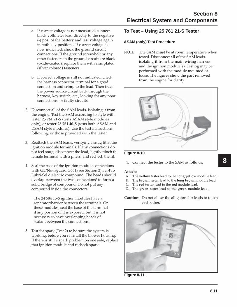
8.11
Section 8Electrical System and Components
8
a. If correct voltage is not measured, connectblack voltmeter lead directly to the negative(-) post of the battery and test voltage againin both key positions. If correct voltage isnow indicated, check the ground circuitconnections. If the ground screw/bolt or anyother fasteners in the ground circuit are black(oxide-coated), replace them with zinc plated(silver colored) fasteners.
b. If correct voltage is still not indicated, checkthe harness connector terminal for a goodconnection and crimp to the lead. Then tracethe power source circuit back through theharness, key switch, etc., looking for any poorconnections, or faulty circuits.
2. Disconnect all of the SAM leads, isolating it fromthe engine. Test the SAM according to style withtester 25 761 21-S (tests ASAM style modulesonly), or tester 25 761 40-S (tests both ASAM andDSAM style modules). Use the test instructionsfollowing, or those provided with the tester.
3. Reattach the SAM leads, verifying a snug fit at theignition module terminals. If any connections donot feel snug, disconnect the lead, lightly pinch thefemale terminal with a pliers, and recheck the fit.
4. Seal the base of the ignition module connectionswith GE/Novaguard G661 (see Section 2) Fel-ProLubri-Sel dielectric compound. The beads shouldoverlap between the two connections† to form asolid bridge of compound. Do not put anycompound inside the connectors.
† The 24 584 15-S ignition modules have aseparator/barrier between the terminals. Onthese modules, seal the base of the terminalif any portion of it is exposed, but it is notnecessary to have overlapping beads ofsealant between the connections.
5. Test for spark (Test 2) to be sure the system isworking, before you reinstall the blower housing.If there is still a spark problem on one side, replacethat ignition module and recheck spark.
To Test – Using 25 761 21-S Tester
ASAM (only) Test Procedure
NOTE: The SAM must be at room temperature whentested. Disconnect all of the SAM leads,isolating it from the main wiring harnessand the ignition module(s). Testing may beperformed with the module mounted orloose. The figures show the part removedfrom the engine for clarity.
Figure 8-10.
1. Connect the tester to the SAM as follows:
Attach:A. The yellow tester lead to the long yellow module lead.B. The brown tester lead to the long brown module lead.C. The red tester lead to the red module lead.D. The green tester lead to the green module lead.
Caution: Do not allow the alligator clip leads to toucheach other.
Figure 8-11.
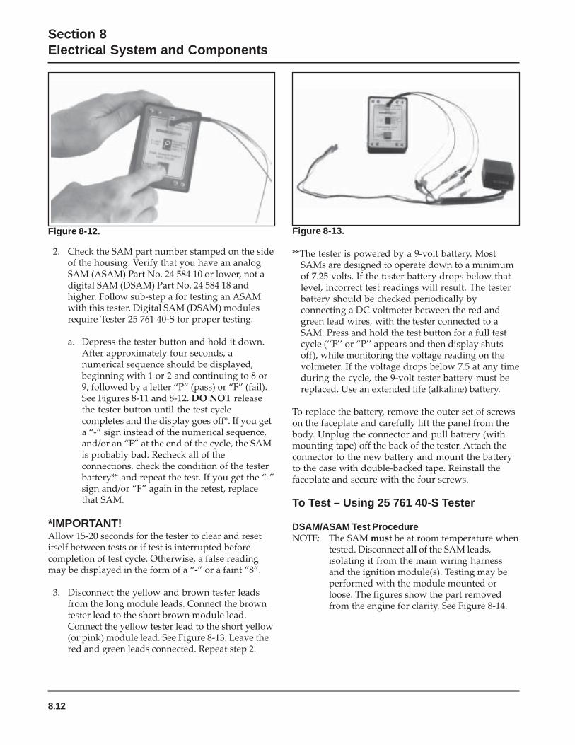
8.12
Section 8Electrical System and Components
Figure 8-12. Figure 8-13.
**The tester is powered by a 9-volt battery. MostSAMs are designed to operate down to a minimumof 7.25 volts. If the tester battery drops below thatlevel, incorrect test readings will result. The testerbattery should be checked periodically byconnecting a DC voltmeter between the red andgreen lead wires, with the tester connected to aSAM. Press and hold the test button for a full testcycle (‘‘F’’ or “P’’ appears and then display shutsoff), while monitoring the voltage reading on thevoltmeter. If the voltage drops below 7.5 at any timeduring the cycle, the 9-volt tester battery must bereplaced. Use an extended life (alkaline) battery.
To replace the battery, remove the outer set of screwson the faceplate and carefully lift the panel from thebody. Unplug the connector and pull battery (withmounting tape) off the back of the tester. Attach theconnector to the new battery and mount the batteryto the case with double-backed tape. Reinstall thefaceplate and secure with the four screws.
To Test – Using 25 761 40-S Tester
DSAM/ASAM Test ProcedureNOTE: The SAM must be at room temperature when
tested. Disconnect all of the SAM leads,isolating it from the main wiring harnessand the ignition module(s). Testing may beperformed with the module mounted orloose. The figures show the part removedfrom the engine for clarity. See Figure 8-14.
2. Check the SAM part number stamped on the sideof the housing. Verify that you have an analogSAM (ASAM) Part No. 24 584 10 or lower, not adigital SAM (DSAM) Part No. 24 584 18 andhigher. Follow sub-step a for testing an ASAMwith this tester. Digital SAM (DSAM) modulesrequire Tester 25 761 40-S for proper testing.
a. Depress the tester button and hold it down.After approximately four seconds, anumerical sequence should be displayed,beginning with 1 or 2 and continuing to 8 or9, followed by a letter “P” (pass) or “F” (fail).See Figures 8-11 and 8-12. DO NOT releasethe tester button until the test cyclecompletes and the display goes off*. If you geta “-” sign instead of the numerical sequence,and/or an “F” at the end of the cycle, the SAMis probably bad. Recheck all of theconnections, check the condition of the testerbattery** and repeat the test. If you get the “-”sign and/or “F” again in the retest, replacethat SAM.
*IMPORTANT!Allow 15-20 seconds for the tester to clear and resetitself between tests or if test is interrupted beforecompletion of test cycle. Otherwise, a false readingmay be displayed in the form of a “-” or a faint “8”.
3. Disconnect the yellow and brown tester leadsfrom the long module leads. Connect the browntester lead to the short brown module lead.Connect the yellow tester lead to the short yellow(or pink) module lead. See Figure 8-13. Leave thered and green leads connected. Repeat step 2.
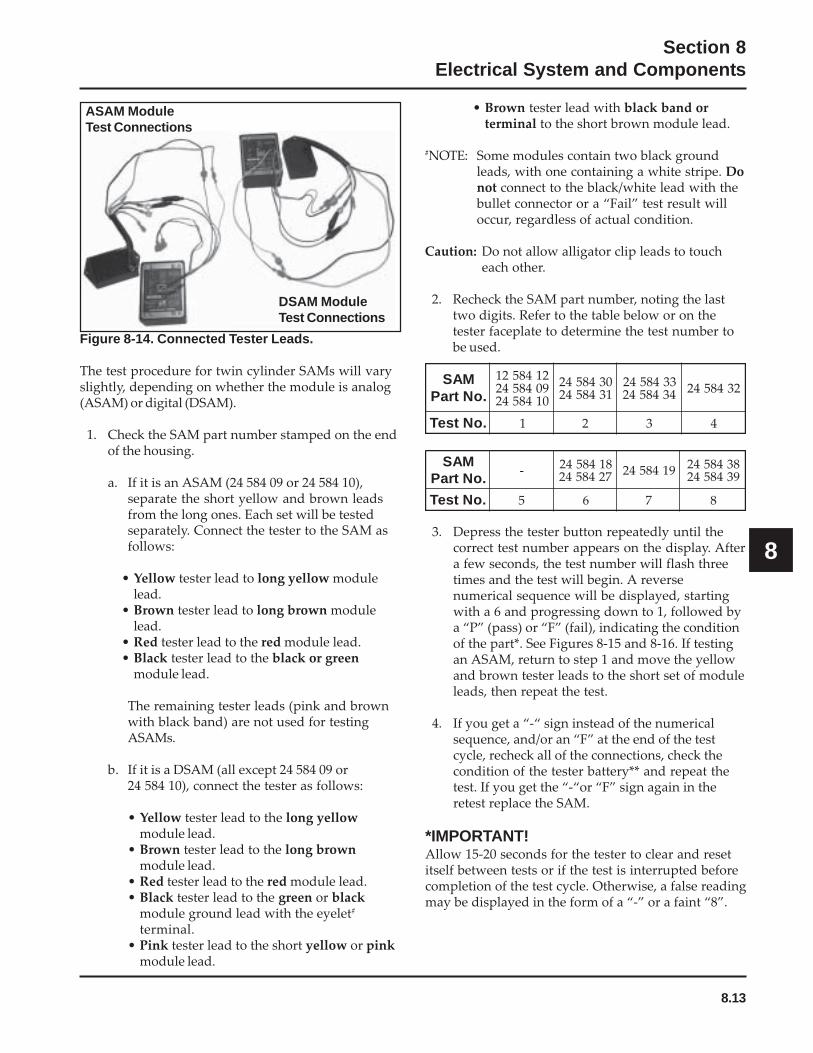
8.13
Section 8Electrical System and Components
8
Figure 8-14. Connected Tester Leads.
The test procedure for twin cylinder SAMs will varyslightly, depending on whether the module is analog(ASAM) or digital (DSAM).
1. Check the SAM part number stamped on the endof the housing.
a. If it is an ASAM (24 584 09 or 24 584 10),separate the short yellow and brown leadsfrom the long ones. Each set will be testedseparately. Connect the tester to the SAM asfollows:
• Yellow tester lead to long yellow modulelead.
• Brown tester lead to long brown modulelead.
• Red tester lead to the red module lead.• Black tester lead to the black or green
module lead.
The remaining tester leads (pink and brownwith black band) are not used for testingASAMs.
b. If it is a DSAM (all except 24 584 09 or24 584 10), connect the tester as follows:
• Yellow tester lead to the long yellowmodule lead.
• Brown tester lead to the long brownmodule lead.
• Red tester lead to the red module lead.• Black tester lead to the green or black
module ground lead with the eyelet#
terminal.• Pink tester lead to the short yellow or pink
module lead.
MAS.oNtraP
- 81485427248542 9148542 8348542
9348542
.oNtseT 5 6 7 8
MAS.oNtraP
214852190485420148542
03485421348542
33485424348542 2348542
.oNtseT 1 2 3 4
3. Depress the tester button repeatedly until thecorrect test number appears on the display. Aftera few seconds, the test number will flash threetimes and the test will begin. A reversenumerical sequence will be displayed, startingwith a 6 and progressing down to 1, followed bya “P” (pass) or “F” (fail), indicating the conditionof the part*. See Figures 8-15 and 8-16. If testingan ASAM, return to step 1 and move the yellowand brown tester leads to the short set of moduleleads, then repeat the test.
4. If you get a “-“ sign instead of the numericalsequence, and/or an “F” at the end of the testcycle, recheck all of the connections, check thecondition of the tester battery** and repeat thetest. If you get the “-“or “F” sign again in theretest replace the SAM.
*IMPORTANT!Allow 15-20 seconds for the tester to clear and resetitself between tests or if the test is interrupted beforecompletion of the test cycle. Otherwise, a false readingmay be displayed in the form of a “-” or a faint “8”.
ASAM ModuleTest Connections
DSAM ModuleTest Connections
• Brown tester lead with black band orterminal to the short brown module lead.
#NOTE: Some modules contain two black groundleads, with one containing a white stripe. Donot connect to the black/white lead with thebullet connector or a “Fail” test result willoccur, regardless of actual condition.
Caution: Do not allow alligator clip leads to toucheach other.
2. Recheck the SAM part number, noting the lasttwo digits. Refer to the table below or on thetester faceplate to determine the test number tobe used.
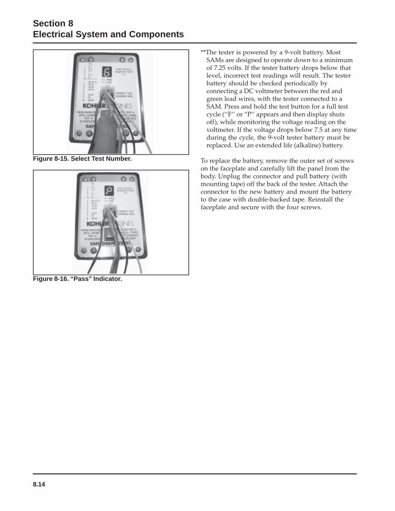
8.14
Section 8Electrical System and Components
Figure 8-16. “Pass” Indicator.
**The tester is powered by a 9-volt battery. MostSAMs are designed to operate down to a minimumof 7.25 volts. If the tester battery drops below thatlevel, incorrect test readings will result. The testerbattery should be checked periodically byconnecting a DC voltmeter between the red andgreen lead wires, with the tester connected to aSAM. Press and hold the test button for a full testcycle (‘‘F’’ or “P’’ appears and then display shutsoff), while monitoring the voltage reading on thevoltmeter. If the voltage drops below 7.5 at any timeduring the cycle, the 9-volt tester battery must bereplaced. Use an extended life (alkaline) battery.
To replace the battery, remove the outer set of screwson the faceplate and carefully lift the panel from thebody. Unplug the connector and pull battery (withmounting tape) off the back of the tester. Attach theconnector to the new battery and mount the batteryto the case with double-backed tape. Reinstall thefaceplate and secure with the four screws.
Figure 8-15. Select Test Number.

8.15
Section 8Electrical System and Components
8
15/20/25 Amp Regulated Charging System
Figure 8-17. Wiring Diagram - 15/20/25 Amp Regulated Battery Charging System with Fixed Timing.
Battery Charging System
GeneralMost engines are equipped with a 15 or 20 ampregulated charging system. Some have a 25 ampregulated charging system. See Figure 8-17 and 8-18for the 15/20/25 amp charging system diagram. Someengines utilize a 3 amp unregulated system withoptional 70 watt lighting circuit. Refer to Figure 8-22.
NOTE: Observe the following guidelines to avoiddamage to the electrical system andcomponents:
• Make sure the battery polarity is correct. Anegative (-) ground system is used.
• Disconnect the rectifier-regulator plug and/or thewiring harness plug before doing any electricwelding on the equipment powered by theengine. Also, disconnect all other electricalaccessories in common ground with the engine.
• Prevent the stator (AC) leads from touching orshorting while the engine is running. This coulddamage the stator.
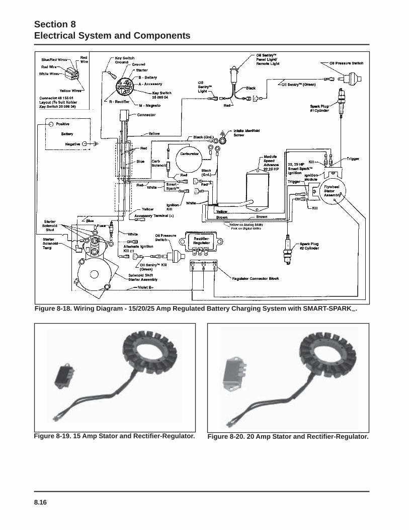
8.16
Section 8Electrical System and Components
Figure 8-18. Wiring Diagram - 15/20/25 Amp Regulated Battery Charging System with SMART-SPARK™.
Figure 8-19. 15 Amp Stator and Rectifier-Regulator. Figure 8-20. 20 Amp Stator and Rectifier-Regulator.
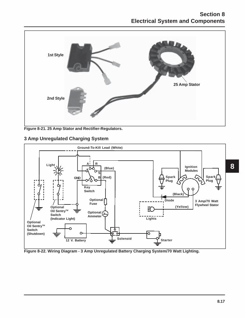
8.17
Section 8Electrical System and Components
8
Ground-To-Kill Lead (White)
Diode
KeySwitch
OptionalOil SentryTM
Switch(Indicator Light)
OptionalOil SentryTM
Switch(Shutdown)
12 V. Battery Solenoid Starter
Lights
(Yellow)
(Black)
3 Amp/70 WattFlywheel Stator
IgnitionModules
SparkPlug
(Red)
(Blue)RA
SBGND
Light
OptionalFuse
OptionalAmmeter
SparkPlug
1st Style
2nd Style
25 Amp Stator
Figure 8-21. 25 Amp Stator and Rectifier-Regulators.
3 Amp Unregulated Charging System
Figure 8-22. Wiring Diagram - 3 Amp Unregulated Battery Charging System/70 Watt Lighting.
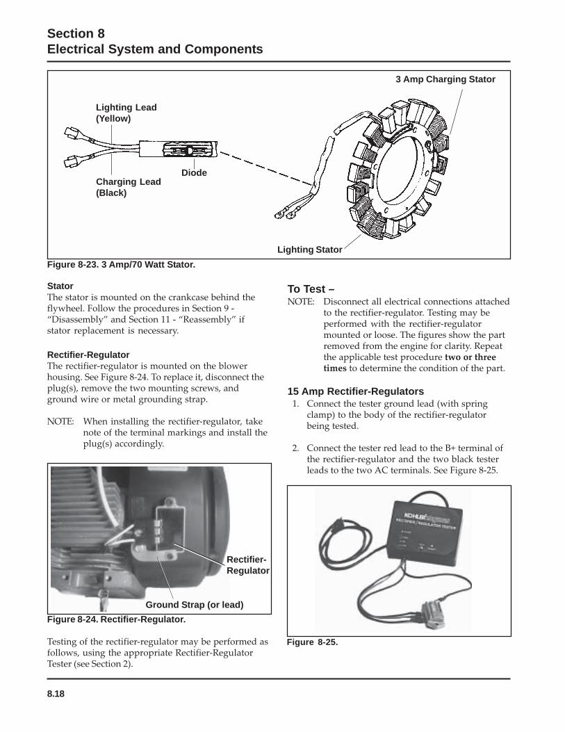
8.18
Section 8Electrical System and Components
Figure 8-24. Rectifier-Regulator.
Testing of the rectifier-regulator may be performed asfollows, using the appropriate Rectifier-RegulatorTester (see Section 2).
To Test –NOTE: Disconnect all electrical connections attached
to the rectifier-regulator. Testing may beperformed with the rectifier-regulatormounted or loose. The figures show the partremoved from the engine for clarity. Repeatthe applicable test procedure two or threetimes to determine the condition of the part.
15 Amp Rectifier-Regulators1. Connect the tester ground lead (with spring
clamp) to the body of the rectifier-regulatorbeing tested.
2. Connect the tester red lead to the B+ terminal ofthe rectifier-regulator and the two black testerleads to the two AC terminals. See Figure 8-25.
Figure 8-25.
Ground Strap (or lead)
Rectifier-Regulator
Lighting Lead(Yellow)
Charging Lead(Black)
Diode
Lighting Stator
3 Amp Charging Stator
Figure 8-23. 3 Amp/70 Watt Stator.
StatorThe stator is mounted on the crankcase behind theflywheel. Follow the procedures in Section 9 -“Disassembly” and Section 11 - “Reassembly” ifstator replacement is necessary.
Rectifier-RegulatorThe rectifier-regulator is mounted on the blowerhousing. See Figure 8-24. To replace it, disconnect theplug(s), remove the two mounting screws, andground wire or metal grounding strap.
NOTE: When installing the rectifier-regulator, takenote of the terminal markings and install theplug(s) accordingly.

8.19
Section 8Electrical System and Components
8
3. Plug the tester into the proper AC outlet/powerfor tester being used. Turn on the power switch.See Figure 8-26. The ‘‘POWER’’ light should beilluminated and one of the four status lights maybe on as well. This does not represent thecondition of the part.
Figure 8-27.
a. If the “OK” (green) light comes on and stayssteady, the part is good and may be used.
b. If any other light is displayed,* the rectifier-regulator is faulty and should not be used.
*NOTE: A flashing “LOW” light can also occur as aresult of an inadequate ground leadconnection. Make certain connection locationis clean and clamp is secure.
Figure 8-26.
4. Press the ‘‘TEST’’ button until a “click” is heardand then release. See Figure 8-27. Momentarilyone of the four lights will illuminate, indicatingthe condition of the part.
20/25 Amp Rectifier-Regulators1. Connect the single lead adapter in between the
B+ (center) terminal of rectifier-regulator beingtested and the squared single end of the tandemadapter lead. See Figure 8-28.
Figure 8-28.
2. Connect the tester ground lead (with springclamp) to the body of the rectifier-regulator.
3. Connect the red lead and one of the black leads tothe pair of terminals on the open end of thetandem adapter lead (connections are notlocation specific).
4. Connect the remaining black lead from the testerto one of the outer AC terminals on the rectifier-regulator. See Figure 8-29.
Figure 8-29.
5. Plug the tester into the proper AC outlet/powerfor tester being used. Turn on the power switch.The ‘‘POWER’’ light should be illuminated andone of the four status lights may be on as well.See Figure 8-26. This does not represent thecondition of the part.
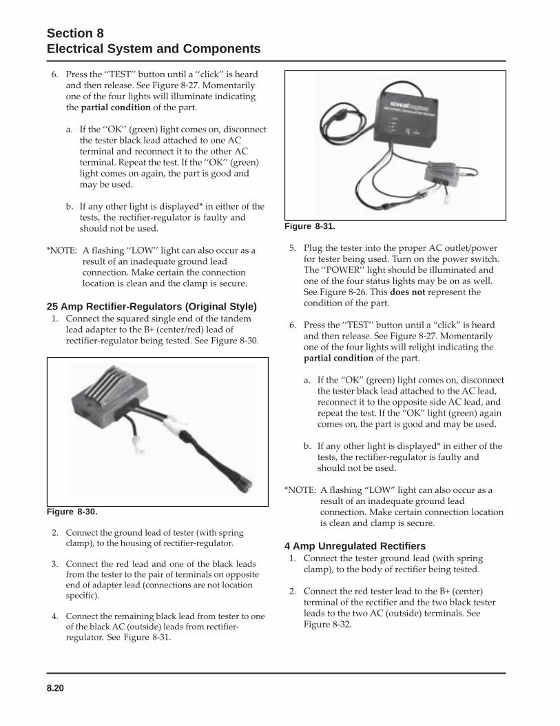
8.20
Section 8Electrical System and Components
6. Press the ‘‘TEST’’ button until a ‘‘click’’ is heardand then release. See Figure 8-27. Momentarilyone of the four lights will illuminate indicatingthe partial condition of the part.
a. If the ‘‘OK’’ (green) light comes on, disconnectthe tester black lead attached to one ACterminal and reconnect it to the other ACterminal. Repeat the test. If the ‘‘OK’’ (green)light comes on again, the part is good andmay be used.
b. If any other light is displayed* in either of thetests, the rectifier-regulator is faulty andshould not be used.
*NOTE: A flashing ‘‘LOW’’ light can also occur as aresult of an inadequate ground leadconnection. Make certain the connectionlocation is clean and the clamp is secure.
25 Amp Rectifier-Regulators (Original Style)1. Connect the squared single end of the tandem
lead adapter to the B+ (center/red) lead ofrectifier-regulator being tested. See Figure 8-30.
Figure 8-30.
2. Connect the ground lead of tester (with springclamp), to the housing of rectifier-regulator.
3. Connect the red lead and one of the black leadsfrom the tester to the pair of terminals on oppositeend of adapter lead (connections are not locationspecific).
4. Connect the remaining black lead from tester to oneof the black AC (outside) leads from rectifier-regulator. See Figure 8-31.
Figure 8-31.
5. Plug the tester into the proper AC outlet/powerfor tester being used. Turn on the power switch.The ‘‘POWER’’ light should be illuminated andone of the four status lights may be on as well.See Figure 8-26. This does not represent thecondition of the part.
6. Press the ‘‘TEST’’ button until a “click” is heardand then release. See Figure 8-27. Momentarilyone of the four lights will relight indicating thepartial condition of the part.
a. If the “OK” (green) light comes on, disconnectthe tester black lead attached to the AC lead,reconnect it to the opposite side AC lead, andrepeat the test. If the “OK” light (green) againcomes on, the part is good and may be used.
b. If any other light is displayed* in either of thetests, the rectifier-regulator is faulty andshould not be used.
*NOTE: A flashing “LOW” light can also occur as aresult of an inadequate ground leadconnection. Make certain connection locationis clean and clamp is secure.
4 Amp Unregulated Rectifiers1. Connect the tester ground lead (with spring
clamp), to the body of rectifier being tested.
2. Connect the red tester lead to the B+ (center)terminal of the rectifier and the two black testerleads to the two AC (outside) terminals. SeeFigure 8-32.

8.21
Section 8Electrical System and Components
8
Figure 8-32.
3. Plug the tester into the proper AC outlet/powerfor tester being used. Turn on the power switch.The ‘‘POWER’’ light should be illuminated andone of the four status lights may be on as well.See Figure 8-26. This does not represent thecondition of the part.
4. Press the ‘‘TEST’’ button until a “click” is heardand then release. See Figure 8-27. Momentarilyeither the ‘‘HIGH’’, ‘‘LOW’’, or ‘‘SHORT’’ lightwill flash.
a. If the “HIGH” light flashes on/off, the part isgood and may be used.
b. If any other light is displayed* the rectifier isfaulty and should not be used.
*NOTE: A flashing “LOW” light can also occur as aresult of an inadequate ground leadconnection. Make certain connection locationis clean and clamp is secure.
Figure 8-33. Connections for Testing Charging System.
DC Voltmeter
Rectifier-Regulator
FlywheelStator
Ammeter
Battery
(-)(+)
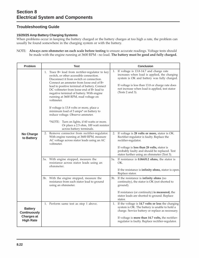
8.22
Section 8Electrical System and Components
Problem Test Conclusion
1. Trace B+ lead from rectifier-regulator to keyswitch, or other accessible connection.Disconnect it from switch or connection.Connect an ammeter from loose end of B+lead to positive terminal of battery. ConnectDC voltmeter from loose end of B+ lead tonegative terminal of battery. With enginerunning at 3600 RPM, read voltage onvoltmeter.
If voltage is 13.8 volts or more, place aminimum load of 5 amps* on battery toreduce voltage. Observe ammeter.
*NOTE: Turn on lights, if 60 watts or more.Or place a 2.5 ohm, 100 watt resistoracross battery terminals.
1. If voltage is 13.8-14.7 and charge rateincreases when load is applied, the chargingsystem is OK and battery was fully charged.
If voltage is less than 13.8 or charge rate doesnot increase when load is applied, test stator(Tests 2 and 3).
2. Remove connector from rectifier-regulator.With engine running at 3600 RPM, measureAC voltage across stator leads using an ACvoltmeter.
2. If voltage is 28 volts or more, stator is OK.Rectifier-regulator is faulty. Replace therectifier-regulator.
If voltage is less than 28 volts, stator isprobably faulty and should be replaced. Teststator further using an ohmmeter (Test 3).
No Chargeto Battery
3a. With engine stopped, measure theresistance across stator leads using anohmmeter.
3a. If resistance is 0.064/0.2 ohms, the stator isOK.
If the resistance is infinity ohms, stator is open.Replace stator.
3b. With the engine stopped, measure theresistance from each stator lead to groundusing an ohmmeter.
3b. If the resistance is infinity ohms (nocontinuity), the stator is OK (not shorted toground).
If resistance (or continuity) is measured, thestator leads are shorted to ground. Replacestator.
1. If the voltage is 14.7 volts or less the chargingsystem is OK. The battery is unable to hold acharge. Service battery or replace as necessary.
If voltage is more than 14.7 volts, the rectifier-regulator is faulty. Replace rectifier-regulator.
1. Perform same test as step 1 above.
BatteryContinuouslyCharges atHigh Rate
Troubleshooting Guide
15/20/25 Amp Battery Charging SystemsWhen problems occur in keeping the battery charged or the battery charges at too high a rate, the problem canusually be found somewhere in the charging system or with the battery.
NOTE: Always zero ohmmeter on each scale before testing to ensure accurate readings. Voltage tests shouldbe made with the engine running at 3600 RPM - no load. The battery must be good and fully charged.
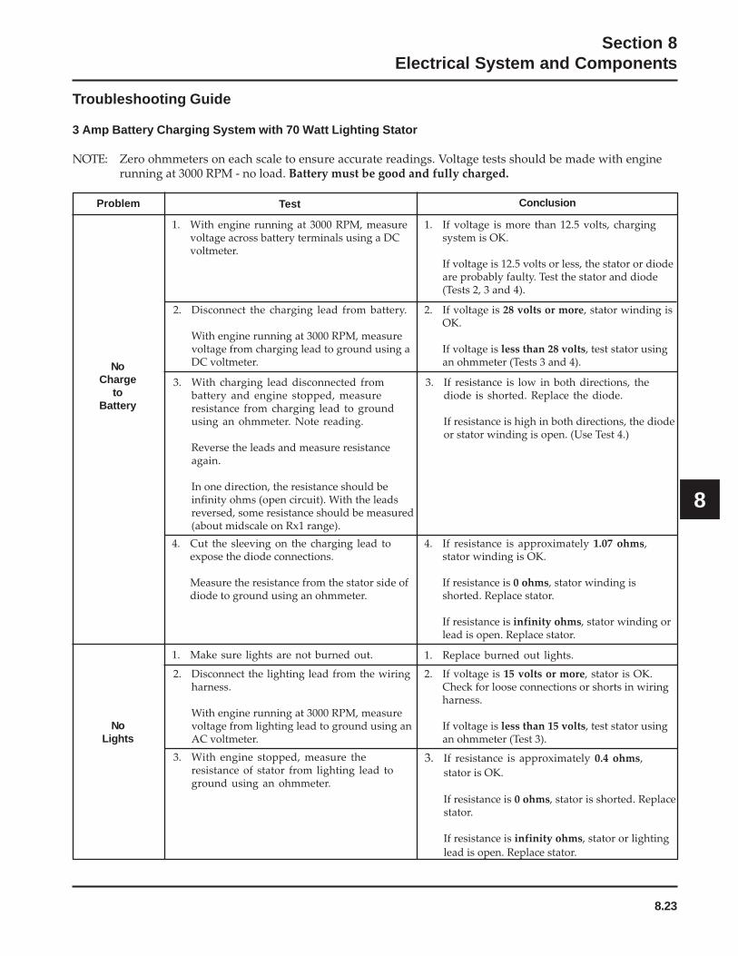
8.23
Section 8Electrical System and Components
8
Troubleshooting Guide
3 Amp Battery Charging System with 70 Watt Lighting Stator
NOTE: Zero ohmmeters on each scale to ensure accurate readings. Voltage tests should be made with enginerunning at 3000 RPM - no load. Battery must be good and fully charged.
Problem
NoCharge
toBattery
NoLights
Test
1. With engine running at 3000 RPM, measurevoltage across battery terminals using a DCvoltmeter.
2. Disconnect the charging lead from battery.
With engine running at 3000 RPM, measurevoltage from charging lead to ground using aDC voltmeter.
3. With charging lead disconnected frombattery and engine stopped, measureresistance from charging lead to groundusing an ohmmeter. Note reading.
Reverse the leads and measure resistanceagain.
In one direction, the resistance should beinfinity ohms (open circuit). With the leadsreversed, some resistance should be measured(about midscale on Rx1 range).
4. Cut the sleeving on the charging lead toexpose the diode connections.
Measure the resistance from the stator side ofdiode to ground using an ohmmeter.
1. Make sure lights are not burned out.
2. Disconnect the lighting lead from the wiringharness.
With engine running at 3000 RPM, measurevoltage from lighting lead to ground using anAC voltmeter.
3. With engine stopped, measure theresistance of stator from lighting lead toground using an ohmmeter.
Conclusion
1. If voltage is more than 12.5 volts, chargingsystem is OK.
If voltage is 12.5 volts or less, the stator or diodeare probably faulty. Test the stator and diode(Tests 2, 3 and 4).
2. If voltage is 28 volts or more, stator winding isOK.
If voltage is less than 28 volts, test stator usingan ohmmeter (Tests 3 and 4).
3. If resistance is low in both directions, thediode is shorted. Replace the diode.
If resistance is high in both directions, the diodeor stator winding is open. (Use Test 4.)
4. If resistance is approximately 1.07 ohms,stator winding is OK.
If resistance is 0 ohms, stator winding isshorted. Replace stator.
If resistance is infinity ohms, stator winding orlead is open. Replace stator.
1. Replace burned out lights.
2. If voltage is 15 volts or more, stator is OK.Check for loose connections or shorts in wiringharness.
If voltage is less than 15 volts, test stator usingan ohmmeter (Test 3).
3. If resistance is approximately 0.4 ohms,
stator is OK.
If resistance is 0 ohms, stator is shorted. Replacestator.
If resistance is infinity ohms, stator or lighting
lead is open. Replace stator.

8.24
Section 8Electrical System and Components
Electric Starting MotorsSome engines in this series use inertia drive startingmotors while most use solenoid shift starters. Theinertia drive types are covered first and the solenoidshift types following.
Starting Motor PrecautionsNOTE: Do not crank the engine continuously for
more than 10 seconds at a time. If the enginedoes not start, allow a 60 second cool-downperiod between starting attempts. Failure tofollow these guidelines can burn out thestarter motor.
NOTE: If the engine develops sufficient speed todisengage the starter but does not keeprunning (a false start), the engine rotationmust be allowed to come to a complete stopbefore attempting to restart the engine. If thestarter is engaged while the flywheel isrotating, the starter pinion and flywheel ringgear may clash, resulting in damage to thestarter.
Problem Possible Fault Correction
1. Check the specific gravity of battery. If low, recharge or replacebattery as necessary.
1. Clean corroded connections and tighten loose connections.2. Replace wires in poor condition and with frayed or broken
insulation.
1. By-pass the switch or solenoid with a jumper wire. If startercranks normally, replace the faulty components. Solenoid ShiftStarters: Perform individual solenoid test procedure. See pages8.39 and 8.40.
1. Check the specific gravity of battery. If low, recharge or replacebattery as necessary.
1. Check for excessively dirty or worn brushes and commutator.Clean using a coarse cloth (not emery cloth).
2. Replace brushes if excessively or unevenly worn.
1. Make sure the clutch or transmission is disengaged or placed inneutral. This is especially important on equipment withhydrostatic drive. The transmission must be exactly in neutral toprevent resistance which could keep the engine from starting.
2. Check for seized engine components such as the bearings,connecting rod, and piston.
StarterDoes NotEnergize
StarterEnergizesbut Turns
Slowly
Battery
Wiring
Starter Switchor Solenoid
Brushes
Transmissionor
Engine
Battery
NOTE: If the starter does not crank the engine, shutoff the starter immediately. Do not makefurther attempts to start the engine until thecondition is corrected.
NOTE: Do not drop the starter or strike the starterframe. Doing so can damage the starter.
Starter Removal and InstallationRefer to the “Disassembly” and “Reassembly”Sections for starter removal and installationprocedures.
Inertia Drive Electric StartersThis subsection covers the operation, troubleshooting,and repair of the inertia drive, permanent magnetelectric starters.
Troubleshooting Guide – Starting Difficulties
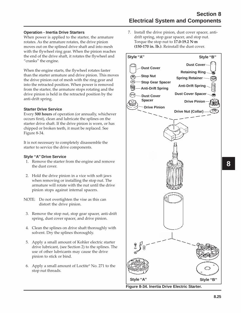
8.25
Section 8Electrical System and Components
8
Operation - Inertia Drive StartersWhen power is applied to the starter, the armaturerotates. As the armature rotates, the drive pinionmoves out on the splined drive shaft and into meshwith the flywheel ring gear. When the pinion reachesthe end of the drive shaft, it rotates the flywheel and“cranks” the engine.
When the engine starts, the flywheel rotates fasterthan the starter armature and drive pinion. This movesthe drive pinion out of mesh with the ring gear andinto the retracted position. When power is removedfrom the starter, the armature stops rotating and thedrive pinion is held in the retracted position by theanti-drift spring.
Starter Drive ServiceEvery 500 hours of operation (or annually, whicheveroccurs first), clean and lubricate the splines on thestarter drive shaft. If the drive pinion is worn, or haschipped or broken teeth, it must be replaced. SeeFigure 8-34.
It is not necessary to completely disassemble thestarter to service the drive components.
Style ‘‘A’’ Drive Service1. Remove the starter from the engine and remove
the dust cover.
2. Hold the drive pinion in a vice with soft jawswhen removing or installing the stop nut. Thearmature will rotate with the nut until the drivepinion stops against internal spacers.
NOTE: Do not overtighten the vise as this candistort the drive pinion.
3. Remove the stop nut, stop gear spacer, anti-driftspring, dust cover spacer, and drive pinion.
4. Clean the splines on drive shaft thoroughly withsolvent. Dry the splines thoroughly.
5. Apply a small amount of Kohler electric starterdrive lubricant, (see Section 2) to the splines. Theuse of other lubricants may cause the drivepinion to stick or bind.
6. Apply a small amount of Loctite® No. 271 to thestop nut threads.
7. Install the drive pinion, dust cover spacer, anti-drift spring, stop gear spacer, and stop nut.Torque the stop nut to 17.0-19.2 N·m(150-170 in. lb.). Reinstall the dust cover.
Dust Cover
Drive Nut (Collar)
Dust Cover Spacer
Retaining Ring
Anti-Drift Spring
Drive Pinion
Dust Cover
Stop Nut
Stop Gear Spacer
Anti-Drift Spring
Dust CoverSpacer
Drive Pinion
Style ‘‘A’’ Style ‘‘B’’
Style ‘‘A’’ Style ‘‘B’’
Spring Retainer
Figure 8-34. Inertia Drive Electric Starter.
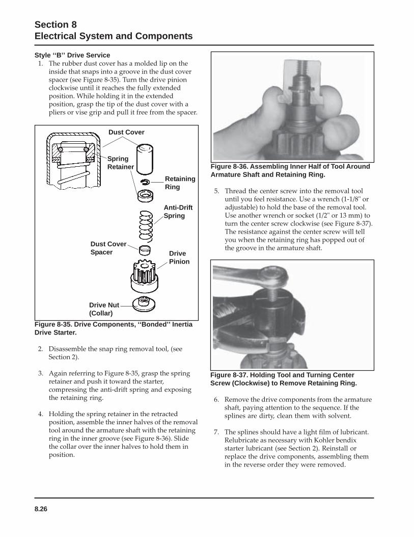
8.26
Section 8Electrical System and Components
Figure 8-36. Assembling Inner Half of Tool AroundArmature Shaft and Retaining Ring.
5. Thread the center screw into the removal tooluntil you feel resistance. Use a wrench (1-1/8" oradjustable) to hold the base of the removal tool.Use another wrench or socket (1/2" or 13 mm) toturn the center screw clockwise (see Figure 8-37).The resistance against the center screw will tellyou when the retaining ring has popped out ofthe groove in the armature shaft.
Style ‘‘B’’ Drive Service1. The rubber dust cover has a molded lip on the
inside that snaps into a groove in the dust coverspacer (see Figure 8-35). Turn the drive pinionclockwise until it reaches the fully extendedposition. While holding it in the extendedposition, grasp the tip of the dust cover with apliers or vise grip and pull it free from the spacer.
Dust Cover
RetainingRing
Anti-DriftSpring
DrivePinion
Drive Nut(Collar)
Dust CoverSpacer
SpringRetainer
Figure 8-35. Drive Components, ‘‘Bonded’’ InertiaDrive Starter.
2. Disassemble the snap ring removal tool, (seeSection 2).
3. Again referring to Figure 8-35, grasp the springretainer and push it toward the starter,compressing the anti-drift spring and exposingthe retaining ring.
4. Holding the spring retainer in the retractedposition, assemble the inner halves of the removaltool around the armature shaft with the retainingring in the inner groove (see Figure 8-36). Slidethe collar over the inner halves to hold them inposition.
Figure 8-37. Holding Tool and Turning CenterScrew (Clockwise) to Remove Retaining Ring.
6. Remove the drive components from the armatureshaft, paying attention to the sequence. If thesplines are dirty, clean them with solvent.
7. The splines should have a light film of lubricant.Relubricate as necessary with Kohler bendixstarter lubricant (see Section 2). Reinstall orreplace the drive components, assembling themin the reverse order they were removed.
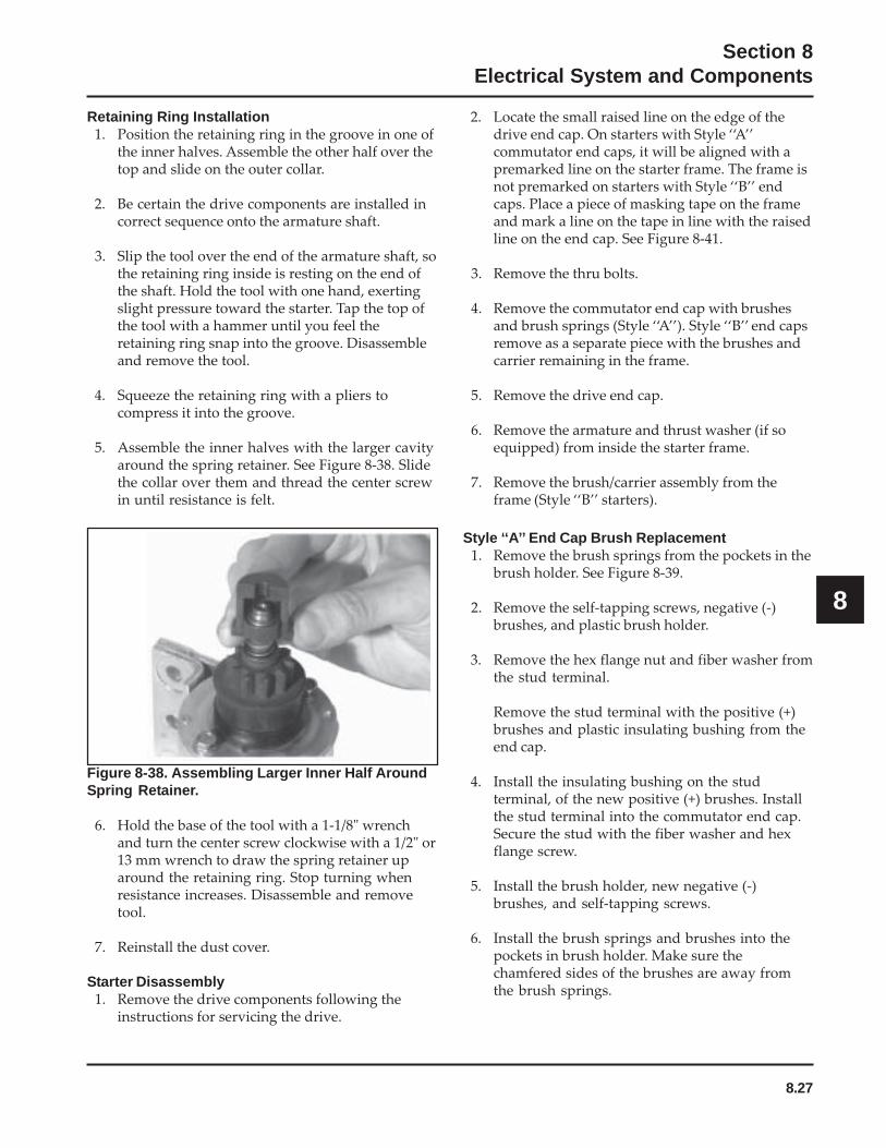
8.27
Section 8Electrical System and Components
8
Retaining Ring Installation1. Position the retaining ring in the groove in one of
the inner halves. Assemble the other half over thetop and slide on the outer collar.
2. Be certain the drive components are installed incorrect sequence onto the armature shaft.
3. Slip the tool over the end of the armature shaft, sothe retaining ring inside is resting on the end ofthe shaft. Hold the tool with one hand, exertingslight pressure toward the starter. Tap the top ofthe tool with a hammer until you feel theretaining ring snap into the groove. Disassembleand remove the tool.
4. Squeeze the retaining ring with a pliers tocompress it into the groove.
5. Assemble the inner halves with the larger cavityaround the spring retainer. See Figure 8-38. Slidethe collar over them and thread the center screwin until resistance is felt.
Figure 8-38. Assembling Larger Inner Half AroundSpring Retainer.
6. Hold the base of the tool with a 1-1/8" wrenchand turn the center screw clockwise with a 1/2" or13 mm wrench to draw the spring retainer uparound the retaining ring. Stop turning whenresistance increases. Disassemble and removetool.
7. Reinstall the dust cover.
Starter Disassembly1. Remove the drive components following the
instructions for servicing the drive.
2. Locate the small raised line on the edge of thedrive end cap. On starters with Style ‘‘A’’commutator end caps, it will be aligned with apremarked line on the starter frame. The frame isnot premarked on starters with Style ‘‘B’’ endcaps. Place a piece of masking tape on the frameand mark a line on the tape in line with the raisedline on the end cap. See Figure 8-41.
3. Remove the thru bolts.
4. Remove the commutator end cap with brushesand brush springs (Style ‘‘A’’). Style ‘‘B’’ end capsremove as a separate piece with the brushes andcarrier remaining in the frame.
5. Remove the drive end cap.
6. Remove the armature and thrust washer (if soequipped) from inside the starter frame.
7. Remove the brush/carrier assembly from theframe (Style ‘‘B’’ starters).
Style ‘‘A’’ End Cap Brush Replacement1. Remove the brush springs from the pockets in the
brush holder. See Figure 8-39.
2. Remove the self-tapping screws, negative (-)brushes, and plastic brush holder.
3. Remove the hex flange nut and fiber washer fromthe stud terminal.
Remove the stud terminal with the positive (+)brushes and plastic insulating bushing from theend cap.
4. Install the insulating bushing on the studterminal, of the new positive (+) brushes. Installthe stud terminal into the commutator end cap.Secure the stud with the fiber washer and hexflange screw.
5. Install the brush holder, new negative (-)brushes, and self-tapping screws.
6. Install the brush springs and brushes into thepockets in brush holder. Make sure thechamfered sides of the brushes are away fromthe brush springs.
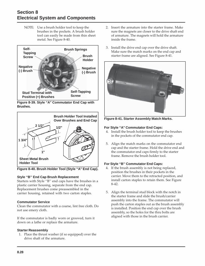
8.28
Section 8Electrical System and Components
NOTE: Use a brush holder tool to keep thebrushes in the pockets. A brush holdertool can easily be made from thin sheetmetal. See Figure 8-40.
Figure 8-40. Brush Holder Tool (Style ‘‘A’’ End Cap).
Style ‘‘B’’ End Cap Brush ReplacementStarters with Style ‘‘B’’ end caps have the brushes in aplastic carrier housing, separate from the end cap.Replacement brushes come preassembled in thecarrier housing, retained with two carton staples.
Commutator ServiceClean the commutator with a coarse, lint free cloth. Donot use emery cloth.
If the commutator is badly worn or grooved, turn itdown on a lathe or replace the armature.
Starter Reassembly1. Place the thrust washer (if so equipped) over the
drive shaft of the armature.
Figure 8-39. Style ‘‘A’’ Commutator End Cap withBrushes.
Self-TappingScrew
Negative(-) Brush
Stud Terminal withPositive (+) Brushes
Brush Springs
BrushHolder
Negative(-) Brush
Self-TappingScrew
Sheet Metal BrushHolder Tool
Brush Holder Tool InstalledOver Brushes and End Cap
1/2"
1"
1 3/4"
2 1/2"
2. Insert the armature into the starter frame. Makesure the magnets are closer to the drive shaft endof armature. The magnets will hold the armatureinside the frame.
3. Install the drive end cap over the drive shaft.Make sure the match marks on the end cap andstarter frame are aligned. See Figure 8-41.
Figure 8-41. Starter Assembly Match Marks.
For Style ‘‘A’’ Commutator End Caps:4. Install the brush holder tool to keep the brushes
in the pockets of the commutator end cap.
5. Align the match marks on the commutator endcap and the starter frame. Hold the drive end andthe commutator end caps firmly to the starterframe. Remove the brush holder tool.
For Style ‘‘B’’ Commutator End Caps:4. If the brush assembly is not being replaced,
position the brushes in their pockets in thecarrier. Move them to the retracted position, andinstall carton staples to retain them. See Figure8-42.
5. Align the terminal stud block with the notch inthe starter frame and slide the brush/carrierassembly into the frame. The commutator willpush the carton staples out as the brush assemblyis installed. Position the end cap over the brushassembly, so the holes for the thru bolts arealigned with those in the brush carrier.
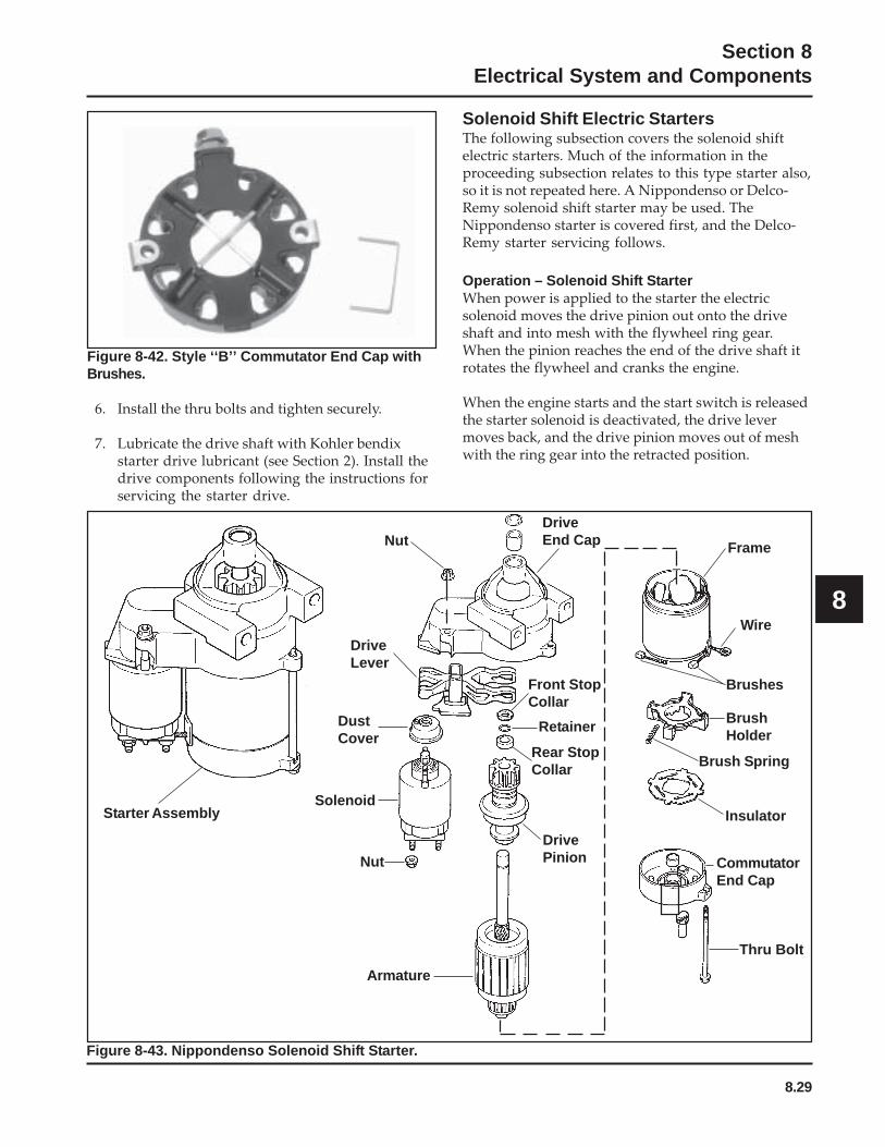
8.29
Section 8Electrical System and Components
8
Figure 8-42. Style ‘‘B’’ Commutator End Cap withBrushes.
6. Install the thru bolts and tighten securely.
7. Lubricate the drive shaft with Kohler bendixstarter drive lubricant (see Section 2). Install thedrive components following the instructions forservicing the starter drive.
Solenoid Shift Electric StartersThe following subsection covers the solenoid shiftelectric starters. Much of the information in theproceeding subsection relates to this type starter also,so it is not repeated here. A Nippondenso or Delco-Remy solenoid shift starter may be used. TheNippondenso starter is covered first, and the Delco-Remy starter servicing follows.
Operation – Solenoid Shift StarterWhen power is applied to the starter the electricsolenoid moves the drive pinion out onto the driveshaft and into mesh with the flywheel ring gear.When the pinion reaches the end of the drive shaft itrotates the flywheel and cranks the engine.
When the engine starts and the start switch is releasedthe starter solenoid is deactivated, the drive levermoves back, and the drive pinion moves out of meshwith the ring gear into the retracted position.
Starter Assembly
Armature
Nut
DriveLever
DustCover
Solenoid
Nut
DrivePinion
DriveEnd Cap Frame
Wire
Brushes
BrushHolder
Brush Spring
Insulator
CommutatorEnd Cap
Thru Bolt
Front StopCollar
Retainer
Rear StopCollar
Figure 8-43. Nippondenso Solenoid Shift Starter.

8.30
Section 8Electrical System and Components
Starter Disassembly1. Disconnect the lead wire from the solenoid.
2. Remove the hex nuts securing the solenoid, andremove the solenoid from the starter assembly.
3. Remove the two thru bolts.
4. Remove the commutator end cap.
5. Remove the insulator and the brush springs fromthe brush spring holder.
6. Remove the armature from the frame.
7. Remove the drive lever and the armature fromthe drive end cap.
NOTE: When removing the lever and thearmature be careful not to lose the thrustwasher.
8. The stop collar consists of two similar pieces heldin place by being snapped over a retainer. Theretainer is held in place by a groove in thearmature shaft. To remove the stop collar the twopieces must be pried off the retainer.
9. When the stop collars are removed the retainercan be removed from the armature shaft. Do notreuse the retainer.
Brush ReplacementThe brushes in the starter are part of the starterframe. Brush kit, Kohler Part No. 52 221 01-S, containsfour replacement brushes and springs. If replacementis necessary, all four brushes should be replaced.
1. Remove the brushes from the brush holder, andremove the brush holder from the frame.
2. Cut the brush lead wire at the edge of the postwith a pair of nippers.
3. File off any burrs on the post.
4. The replacement brushes have a solid portion onthem which should be crimped on the post.
5. Solder the crimped portion to the post.
6. Replace the brush holder in the frame and placethe brushes in the brush holder. Reinstall thesprings.
Starter ServiceEvery 500 hours of operation (or annually, whichevercomes first), solenoid shift starters must bedisassembled, cleaned and relubricated. Apply starterlubricant (see Section 2) to the lever and shaft. Failureto do so could result in an accumulation of dirt ordebris that might prevent the engine from startingand could cause damage to the starter or the flywheel.Service may be necessary more frequently underdusty or dirty conditions.
Starter Reassembly1. Insert the rear stop collar on the armature shaft.
2. Place the retainer in the groove on the armatureshaft.
NOTE: Always use a new retainer. Tighten theretainer in the groove to secure.
3. Fit the front stop collar over the shaft and bringthe front and the rear stop collars together overthe retainer. Using two pairs of pliers apply evenforce to the two collars until they snap over theretainer and nest into one another.
4. Reassemble the remaining components of thestarter in reverse order from disassembly.
Delco-Remy Starters
Figure 8-44. Completed Delco-Remy Starter.
Starter Disassembly1. Remove the hex nut and disconnect the positive
(+) brush lead/bracket from the solenoid terminal.
2. Remove the three screws securing the solenoid tothe starter. See Figure 8-45.
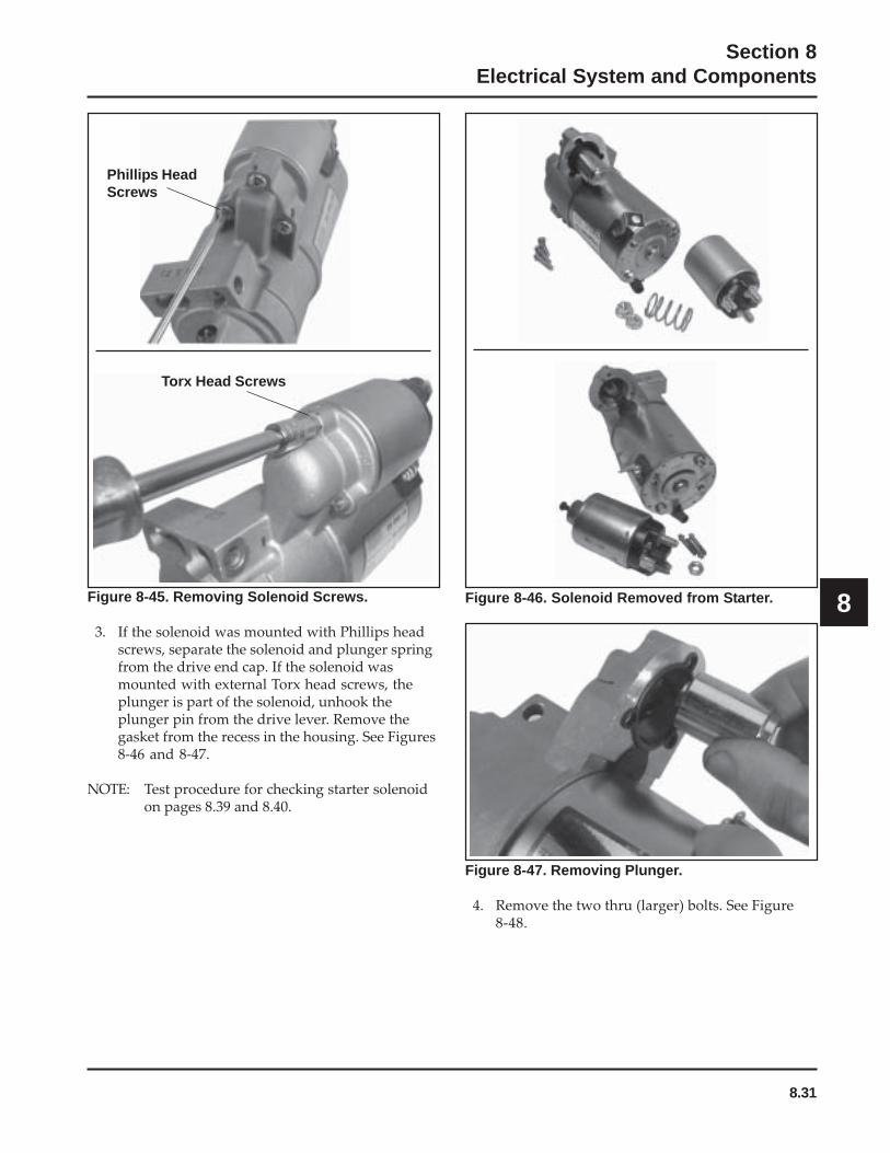
8.31
Section 8Electrical System and Components
8Figure 8-45. Removing Solenoid Screws.
3. If the solenoid was mounted with Phillips headscrews, separate the solenoid and plunger springfrom the drive end cap. If the solenoid wasmounted with external Torx head screws, theplunger is part of the solenoid, unhook theplunger pin from the drive lever. Remove thegasket from the recess in the housing. See Figures8-46 and 8-47.
NOTE: Test procedure for checking starter solenoidon pages 8.39 and 8.40.
Figure 8-47. Removing Plunger.
4. Remove the two thru (larger) bolts. See Figure8-48.
Figure 8-46. Solenoid Removed from Starter.
Phillips HeadScrews
Torx Head Screws

8.32
Section 8Electrical System and Components
Figure 8-48. Removing Thru Bolts.
5. Remove the commutator end plate assembly,containing the brush holder, brushes, springs,and locking caps. Remove the thrust washerfrom inside the commutator end. See Figure 8-49.
Figure 8-49. Removing Commutator End PlateAssembly.
6. Remove the frame from the armature and driveend cap. See Figure 8-50. Figure 8-52. Armature and Lever Removed.
10. Push the stop collar down to expose the retainingring. See Figure 8-53.
Figure 8-50. Starter Frame Removed.
7. Remove the drive lever pivot bushing andbacking plate from the end cap. See Figure 8-51.
Figure 8-51.
8. Take out the drive lever and pull the armatureout of the drive end cap. See Figure 8-52.
9. Remove the thrust washer from the armatureshaft. See Figure 8-52.
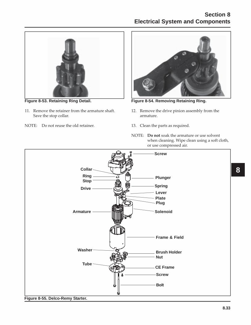
8.33
Section 8Electrical System and Components
8
Figure 8-54. Removing Retaining Ring.
12. Remove the drive pinion assembly from thearmature.
13. Clean the parts as required.
NOTE: Do not soak the armature or use solventwhen cleaning. Wipe clean using a soft cloth,or use compressed air.
Figure 8-53. Retaining Ring Detail.
11. Remove the retainer from the armature shaft.Save the stop collar.
NOTE: Do not reuse the old retainer.
Lever
Solenoid
CE Frame
Bolt
RingStop
Drive
Armature
Washer
Screw
Plunger
Spring
Plate
Collar
Tube
Screw
Plug
Frame & Field
Brush HolderNut
Figure 8-55. Delco-Remy Starter.
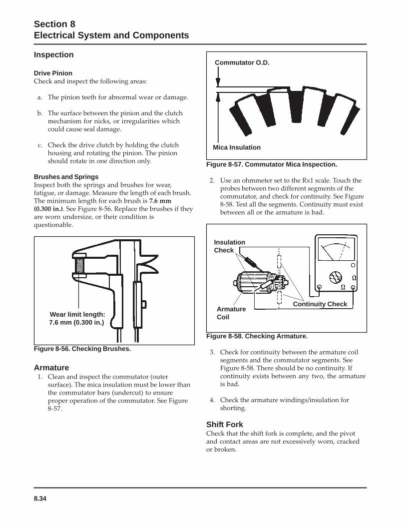
8.34
Section 8Electrical System and Components
Figure 8-56. Checking Brushes.
Armature1. Clean and inspect the commutator (outer
surface). The mica insulation must be lower thanthe commutator bars (undercut) to ensureproper operation of the commutator. See Figure8-57.
Figure 8-58. Checking Armature.
3. Check for continuity between the armature coilsegments and the commutator segments. SeeFigure 8-58. There should be no continuity. Ifcontinuity exists between any two, the armatureis bad.
4. Check the armature windings/insulation forshorting.
Shift ForkCheck that the shift fork is complete, and the pivotand contact areas are not excessively worn, crackedor broken.
Inspection
Drive PinionCheck and inspect the following areas:
a. The pinion teeth for abnormal wear or damage.
b. The surface between the pinion and the clutchmechanism for nicks, or irregularities whichcould cause seal damage.
c. Check the drive clutch by holding the clutchhousing and rotating the pinion. The pinionshould rotate in one direction only.
Brushes and SpringsInspect both the springs and brushes for wear,fatigue, or damage. Measure the length of each brush.The minimum length for each brush is 7.6 mm(0.300 in.). See Figure 8-56. Replace the brushes if theyare worn undersize, or their condition isquestionable.
Figure 8-57. Commutator Mica Inspection.
2. Use an ohmmeter set to the Rx1 scale. Touch theprobes between two different segments of thecommutator, and check for continuity. See Figure8-58. Test all the segments. Continuity must existbetween all or the armature is bad.
Wear limit length:7.6 mm (0.300 in.)
Commutator O.D.
Mica Insulation
Continuity CheckArmatureCoil
InsulationCheck
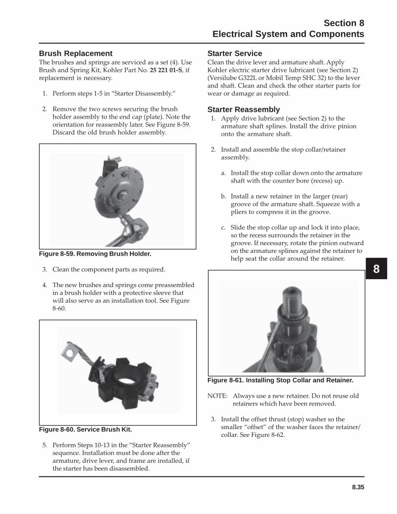
8.35
Section 8Electrical System and Components
8
Figure 8-60. Service Brush Kit.
5. Perform Steps 10-13 in the “Starter Reassembly”sequence. Installation must be done after thearmature, drive lever, and frame are installed, ifthe starter has been disassembled.
Brush ReplacementThe brushes and springs are serviced as a set (4). UseBrush and Spring Kit, Kohler Part No. 25 221 01-S, ifreplacement is necessary.
1. Perform steps 1-5 in “Starter Disassembly.”
2. Remove the two screws securing the brushholder assembly to the end cap (plate). Note theorientation for reassembly later. See Figure 8-59.Discard the old brush holder assembly.
Figure 8-59. Removing Brush Holder.
3. Clean the component parts as required.
4. The new brushes and springs come preassembledin a brush holder with a protective sleeve thatwill also serve as an installation tool. See Figure8-60.
Starter ServiceClean the drive lever and armature shaft. ApplyKohler electric starter drive lubricant (see Section 2)(Versilube G322L or Mobil Temp SHC 32) to the leverand shaft. Clean and check the other starter parts forwear or damage as required.
Starter Reassembly1. Apply drive lubricant (see Section 2) to the
armature shaft splines. Install the drive piniononto the armature shaft.
2. Install and assemble the stop collar/retainerassembly.
a. Install the stop collar down onto the armatureshaft with the counter bore (recess) up.
b. Install a new retainer in the larger (rear)groove of the armature shaft. Squeeze with apliers to compress it in the groove.
c. Slide the stop collar up and lock it into place,so the recess surrounds the retainer in thegroove. If necessary, rotate the pinion outwardon the armature splines against the retainer tohelp seat the collar around the retainer.
Figure 8-61. Installing Stop Collar and Retainer.
NOTE: Always use a new retainer. Do not reuse oldretainers which have been removed.
3. Install the offset thrust (stop) washer so thesmaller “offset” of the washer faces the retainer/collar. See Figure 8-62.

8.36
Section 8Electrical System and Components
Figure 8-62. Installing Thrust Washer.
4. Apply a small amount of oil to the bearing in thedrive end cap, and install the armature with thedrive pinion.
5. Lubricate the fork end and center pivot of thedrive lever with drive lubricant (see Section 2).Position the fork end into the space between thecaptured washer and the rear of the pinion.
6. Slide the armature into the drive end cap, and atthe same time seat the drive lever into thehousing.
NOTE: Correctly installed, the center pivot sectionof the drive lever will be flush or below themachined surface of the housing whichreceives the backup washer. See Figure 8-63.
Figure 8-63. Installing Armature and Pivot Lever.
Figure 8-64. Installing Backup Washer andGrommet.
8. Install the frame, with the small notch forward,onto the armature and drive end cap. Align thenotch with the corresponding section in therubber grommet. Install the drain tube in the rearcutout, if it was removed previously. See Figure8-65.
7. Install the backup washer, followed by therubber grommet, into the matching recess of thedrive end cap. The molded recesses in thegrommet should be “out”, matching and alignedwith those in the end cap. See Figure 8-64.
Figure 8-65. Installing Frame and Drain Tube.
9. Install the flat thrust washer onto the commutatorend of the armature shaft. See Figure 8-66.

8.37
Section 8Electrical System and Components
8
Figure 8-66. Installing Thrust Washer.
10. Starter reassembly when replacing the Brushes/Brush Holder Assembly:
a. Hold the starter assembly vertically on theend housing, and carefully position theassembled brush holder assembly, with thesupplied protective tube, against the end ofthe commutator/armature. The mountingscrew holes in the metal clips must be “up/out.” Slide the brush holder assembly downinto place around the commutator, and installthe positive (+) brush lead grommet in thecutout of the frame. See Figure 8-67. Theprotective tube may be saved and used forfuture servicing.
Figure 8-68. Removing Retaining Clips.
b. Position each of the brushes back in their slotsso they are flush with the I.D. of the brushholder assembly. Insert the Brush InstallationTool (with extension), or use the tube describedabove from a prior brush installation, throughthe brush holder assembly, so the holes in themetal mounting clips are “up/out.”
c. Install the brush springs and snap on the fourretainer caps. See Figure 8-69.
Figure 8-67. Installing Brush Holder Assembly withSupplied Tube.
Starter reassembly when not replacing the Brushes/Brush Holder Assembly:
a. Carefully unhook the retaining caps from overeach of the brush assemblies. Do not lose thesprings.
Figure 8-69. Brush Installation Tool with Extension.
d. Hold the starter assembly vertically on theend housing, and carefully place the tool (withextension) and assembled original brushholder assembly onto the end of the armatureshaft. Slide the brush holder assembly downinto place around the commutator, install thepositive (+) brush lead grommet in the cutoutof the frame. See Figure 8-70.
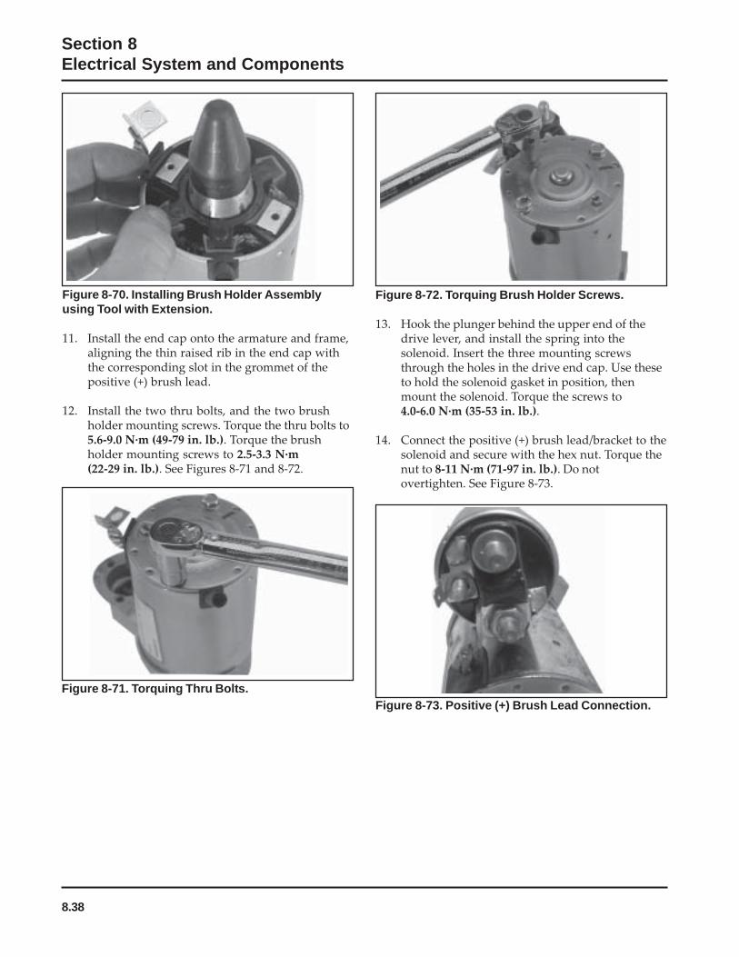
8.38
Section 8Electrical System and Components
Figure 8-70. Installing Brush Holder Assemblyusing Tool with Extension.
11. Install the end cap onto the armature and frame,aligning the thin raised rib in the end cap withthe corresponding slot in the grommet of thepositive (+) brush lead.
12. Install the two thru bolts, and the two brushholder mounting screws. Torque the thru bolts to5.6-9.0 N·m (49-79 in. lb.). Torque the brushholder mounting screws to 2.5-3.3 N·m(22-29 in. lb.). See Figures 8-71 and 8-72.
Figure 8-71. Torquing Thru Bolts.
Figure 8-72. Torquing Brush Holder Screws.
13. Hook the plunger behind the upper end of thedrive lever, and install the spring into thesolenoid. Insert the three mounting screwsthrough the holes in the drive end cap. Use theseto hold the solenoid gasket in position, thenmount the solenoid. Torque the screws to4.0-6.0 N·m (35-53 in. lb.).
14. Connect the positive (+) brush lead/bracket to thesolenoid and secure with the hex nut. Torque thenut to 8-11 N·m (71-97 in. lb.). Do notovertighten. See Figure 8-73.
Figure 8-73. Positive (+) Brush Lead Connection.
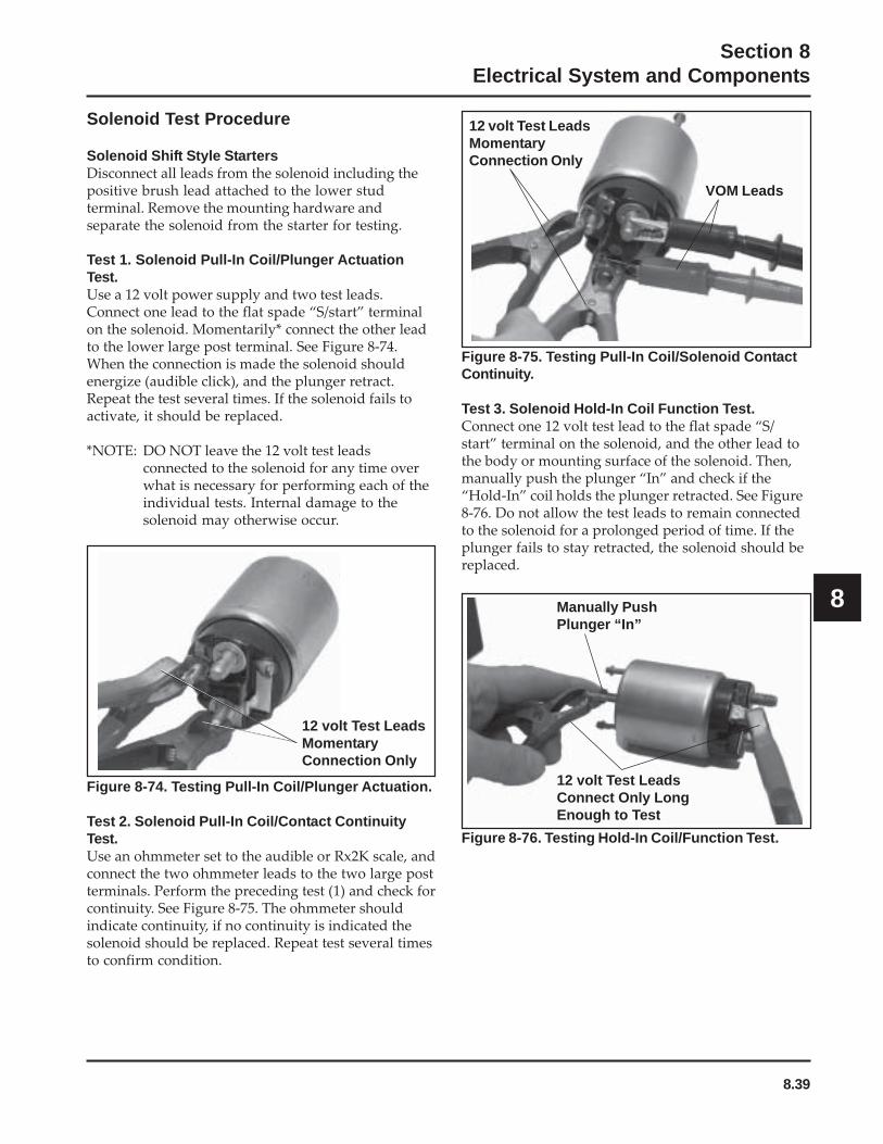
8.39
Section 8Electrical System and Components
8
Figure 8-74. Testing Pull-In Coil/Plunger Actuation.
Test 2. Solenoid Pull-In Coil/Contact ContinuityTest.Use an ohmmeter set to the audible or Rx2K scale, andconnect the two ohmmeter leads to the two large postterminals. Perform the preceding test (1) and check forcontinuity. See Figure 8-75. The ohmmeter shouldindicate continuity, if no continuity is indicated thesolenoid should be replaced. Repeat test several timesto confirm condition.
Solenoid Test Procedure
Solenoid Shift Style StartersDisconnect all leads from the solenoid including thepositive brush lead attached to the lower studterminal. Remove the mounting hardware andseparate the solenoid from the starter for testing.
Test 1. Solenoid Pull-In Coil/Plunger ActuationTest.Use a 12 volt power supply and two test leads.Connect one lead to the flat spade “S/start” terminalon the solenoid. Momentarily* connect the other leadto the lower large post terminal. See Figure 8-74.When the connection is made the solenoid shouldenergize (audible click), and the plunger retract.Repeat the test several times. If the solenoid fails toactivate, it should be replaced.
*NOTE: DO NOT leave the 12 volt test leadsconnected to the solenoid for any time overwhat is necessary for performing each of theindividual tests. Internal damage to thesolenoid may otherwise occur.
12 volt Test LeadsMomentaryConnection Only
Figure 8-75. Testing Pull-In Coil/Solenoid ContactContinuity.
Test 3. Solenoid Hold-In Coil Function Test.Connect one 12 volt test lead to the flat spade “S/start” terminal on the solenoid, and the other lead tothe body or mounting surface of the solenoid. Then,manually push the plunger “In” and check if the“Hold-In” coil holds the plunger retracted. See Figure8-76. Do not allow the test leads to remain connectedto the solenoid for a prolonged period of time. If theplunger fails to stay retracted, the solenoid should bereplaced.
12 volt Test LeadsMomentaryConnection Only
VOM Leads
Manually PushPlunger “In”
12 volt Test LeadsConnect Only LongEnough to Test
Figure 8-76. Testing Hold-In Coil/Function Test.

8.40
Section 8Electrical System and Components
PlungerPushed “In”
VOM MeterLeads
12 volt Test Leads
Test 4. Solenoid Hold-In Coil/Contact ContinuityTest.Use an ohmmeter set to the audible or Rx2K scale, andconnect the two ohmmeter leads to the two large postterminals. Perform the preceding test (3) and check forcontinuity. See Figure 8-77. The meter should indicatecontinuity, if no continuity is indicated the solenoidshould be replaced. Repeat test several times toconfirm condition.
Figure 8-77. Testing Hold-In Coil/Solenoid ContactContinuity.
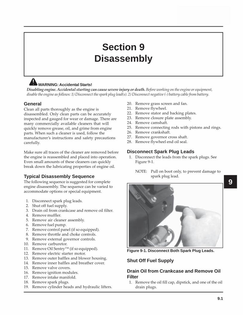
9.1
Section 9Disassembly
9
Section 9Disassembly
WARNING: Accidental Starts!Disabling engine. Accidental starting can cause severe injury or death. Before working on the engine or equipment,disable the engine as follows: 1) Disconnect the spark plug lead(s). 2) Disconnect negative (-) battery cable from battery.
20. Remove grass screen and fan.21. Remove flywheel.22. Remove stator and backing plates.23. Remove closure plate assembly.24. Remove camshaft.25. Remove connecting rods with pistons and rings.26. Remove crankshaft.27. Remove governor cross shaft.28. Remove flywheel end oil seal.
Disconnect Spark Plug Leads1. Disconnect the leads from the spark plugs. See
Figure 9-1.
NOTE: Pull on boot only, to prevent damage tospark plug lead.
GeneralClean all parts thoroughly as the engine isdisassembled. Only clean parts can be accuratelyinspected and gauged for wear or damage. There aremany commercially available cleaners that willquickly remove grease, oil, and grime from engineparts. When such a cleaner is used, follow themanufacturer’s instructions and safety precautionscarefully.
Make sure all traces of the cleaner are removed beforethe engine is reassembled and placed into operation.Even small amounts of these cleaners can quicklybreak down the lubricating properties of engine oil.
Typical Disassembly SequenceThe following sequence is suggested for completeengine disassembly. The sequence can be varied toaccommodate options or special equipment.
1. Disconnect spark plug leads.2. Shut off fuel supply.3. Drain oil from crankcase and remove oil filter.4. Remove muffler.5. Remove air cleaner assembly.6. Remove fuel pump.7. Remove control panel (if so equipped).8. Remove throttle and choke controls.9. Remove external governor controls.
10. Remove carburetor.11. Remove Oil Sentry™ (if so equipped).12. Remove electric starter motor.13. Remove outer baffles and blower housing.14. Remove inner baffles and breather cover.15. Remove valve covers.16. Remove ignition modules.17. Remove intake manifold.18. Remove spark plugs.19. Remove cylinder heads and hydraulic lifters.
Figure 9-1. Disconnect Both Spark Plug Leads.
Shut Off Fuel Supply
Drain Oil from Crankcase and Remove OilFilter
1. Remove the oil fill cap, dipstick, and one of the oildrain plugs.
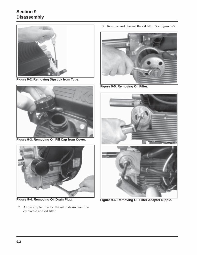
9.2
Section 9Disassembly
Figure 9-2. Removing Dipstick from Tube.
Figure 9-3. Removing Oil Fill Cap from Cover.
Figure 9-6. Removing Oil Filter Adapter Nipple.Figure 9-4. Removing Oil Drain Plug.
2. Allow ample time for the oil to drain from thecrankcase and oil filter.
Figure 9-5. Removing Oil Filter.
3. Remove and discard the oil filter. See Figure 9-5.

9.3
Section 9Disassembly
9
Figure 9-7. Removing Oil Cooler.
4. An oil cooler is standard equipment on somemodels and an option on others. It may be a castaluminum housing, part of the oil filter adapter,or attached to the blower housing, separatedfrom the oil filter adapter. If so equipped, removethe adapter and the cooler. See Figures 9-6 and9-7.
Remove Muffler1. Remove the exhaust system and attaching
hardware from the engine. On engines equippedwith a port liner, remove it now.
Remove Air Cleaner Assembly
Standard Air Cleaner1. Unhook the latches or loosen the knob and
remove the cover. Refer to Section 4.
2. Remove the wing nut from the element cover.
3. Remove the element cover, the air cleanerelement with precleaner and the stud seal.
Figure 9-8. Removing Air Cleaner Base Retainer.
Figure 9-9. Rear Air Cleaner Bracket Screws.
5. Remove the bracket then remove the base andgasket while carefully pulling the rubberbreather tube through the base. See Figure 9-10.
Figure 9-10. Removing Breather Tube from Base.
4. Remove the hex flange screws securing thebracket and base. See Figure 9-8. Two additionalrear screws must be removed if the enginecontains a rear air cleaner support bracket. SeeFigure 9-9.
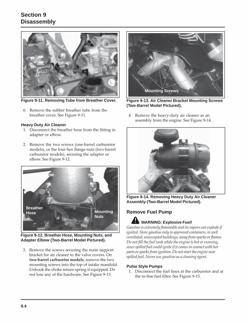
9.4
Section 9Disassembly
Figure 9-11. Removing Tube from Breather Cover.
6. Remove the rubber breather tube from thebreather cover. See Figure 9-11.
Heavy Duty Air Cleaner1. Disconnect the breather hose from the fitting in
adapter or elbow.
2. Remove the two screws (one-barrel carburetormodels), or the four hex flange nuts (two-barrelcarburetor models), securing the adapter orelbow. See Figure 9-12.
Figure 9-12. Breather Hose, Mounting Nuts, andAdapter Elbow (Two-Barrel Model Pictured).
3. Remove the screws securing the main supportbracket for air cleaner to the valve covers. Ontwo-barrel carburetor models, remove the twomounting screws into the top of intake manifold.Unhook the choke return spring if equipped. Donot lose any of the hardware. See Figure 9-13.
MountingNuts
BreatherHose
Figure 9-13. Air Cleaner Bracket Mounting Screws(Two-Barrel Model Pictured).
4. Remove the heavy-duty air cleaner as anassembly from the engine. See Figure 9-14.
Mounting Screws
Figure 9-14. Removing Heavy Duty Air CleanerAssembly (Two-Barrel Model Pictured).
Remove Fuel Pump
WARNING: Explosive Fuel!Gasoline is extremely flammable and its vapors can explode ifignited. Store gasoline only in approved containers, in wellventilated, unoccupied buildings, away from sparks or flames.Do not fill the fuel tank while the engine is hot or running,since spilled fuel could ignite if it comes in contact with hotparts or sparks from ignition. Do not start the engine nearspilled fuel. Never use gasoline as a cleaning agent.
Pulse Style Pumps1. Disconnect the fuel lines at the carburetor and at
the in-line fuel filter. See Figure 9-15.

9.5
Section 9Disassembly
9Figure 9-16. Disconnecting Pulse Line fromCrankcase.
Figure 9-17. Disconnecting Pulse Line from ValveCover (Early Models).
2. Disconnect the pulse (vacuum) line from thecrankcase, or from the valve cover on earliermodels. See Figures 9-16 and 9-17.
Figure 9-15. Disconnecting Fuel Inlet Line atCarburetor.
3. Remove the two hex flange screws securing thefuel pump to the bracket or to the blowerhousing. See Figure 9-18. The fuel pump bodymay be metal or plastic.
Figure 9-18. Removing Screws Holding Fuel Pump(Metal Bodied Pump Shown).
4. Note or mark the orientation of the fuel pump,then remove the fuel pump with lines attachedas shown in Figure 9-19.
Figure 9-19. Remove Fuel Pump and Lines.
Mechanical Fuel PumpThe mechanical style fuel pump is part of the valvecover assembly. See Figure 9-20.
1. Disconnect the fuel lines at the pump outlet andat the in-line fuel filter.
2. The fuel pump will be removed with the valvecover. Refer to the valve cover removalprocedure.
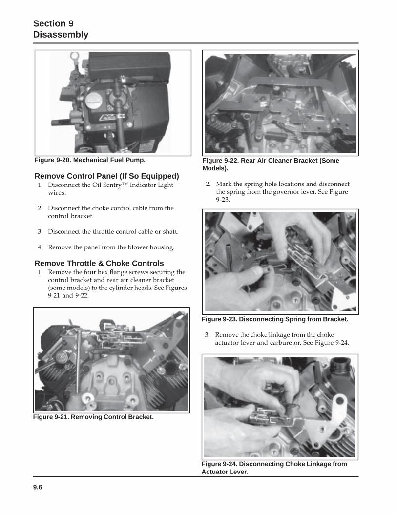
9.6
Section 9Disassembly
Figure 9-22. Rear Air Cleaner Bracket (SomeModels).
2. Mark the spring hole locations and disconnectthe spring from the governor lever. See Figure9-23.
Figure 9-23. Disconnecting Spring from Bracket.
3. Remove the choke linkage from the chokeactuator lever and carburetor. See Figure 9-24.
Figure 9-24. Disconnecting Choke Linkage fromActuator Lever.
Figure 9-21. Removing Control Bracket.
Figure 9-20. Mechanical Fuel Pump.
Remove Control Panel (If So Equipped)1. Disconnect the Oil Sentry™ Indicator Light
wires.
2. Disconnect the choke control cable from thecontrol bracket.
3. Disconnect the throttle control cable or shaft.
4. Remove the panel from the blower housing.
Remove Throttle & Choke Controls1. Remove the four hex flange screws securing the
control bracket and rear air cleaner bracket(some models) to the cylinder heads. See Figures9-21 and 9-22.
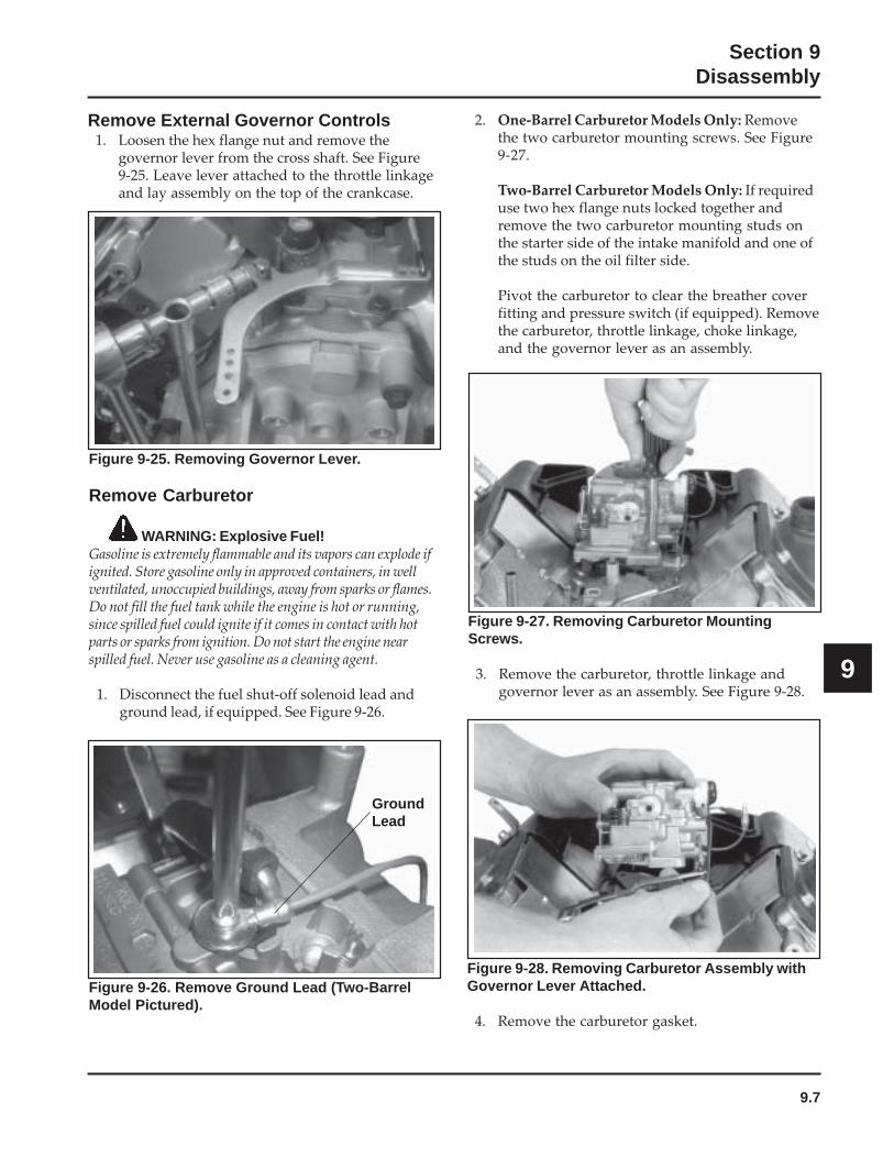
9.7
Section 9Disassembly
9
Remove External Governor Controls1. Loosen the hex flange nut and remove the
governor lever from the cross shaft. See Figure9-25. Leave lever attached to the throttle linkageand lay assembly on the top of the crankcase.
Figure 9-25. Removing Governor Lever.
Remove Carburetor
WARNING: Explosive Fuel!Gasoline is extremely flammable and its vapors can explode ifignited. Store gasoline only in approved containers, in wellventilated, unoccupied buildings, away from sparks or flames.Do not fill the fuel tank while the engine is hot or running,since spilled fuel could ignite if it comes in contact with hotparts or sparks from ignition. Do not start the engine nearspilled fuel. Never use gasoline as a cleaning agent.
1. Disconnect the fuel shut-off solenoid lead andground lead, if equipped. See Figure 9-26.
Figure 9-28. Removing Carburetor Assembly withGovernor Lever Attached.
4. Remove the carburetor gasket.
Figure 9-26. Remove Ground Lead (Two-BarrelModel Pictured).
GroundLead
2. One-Barrel Carburetor Models Only: Removethe two carburetor mounting screws. See Figure9-27.
Two-Barrel Carburetor Models Only: If requireduse two hex flange nuts locked together andremove the two carburetor mounting studs onthe starter side of the intake manifold and one ofthe studs on the oil filter side.
Pivot the carburetor to clear the breather coverfitting and pressure switch (if equipped). Removethe carburetor, throttle linkage, choke linkage,and the governor lever as an assembly.
Figure 9-27. Removing Carburetor MountingScrews.
3. Remove the carburetor, throttle linkage andgovernor lever as an assembly. See Figure 9-28.
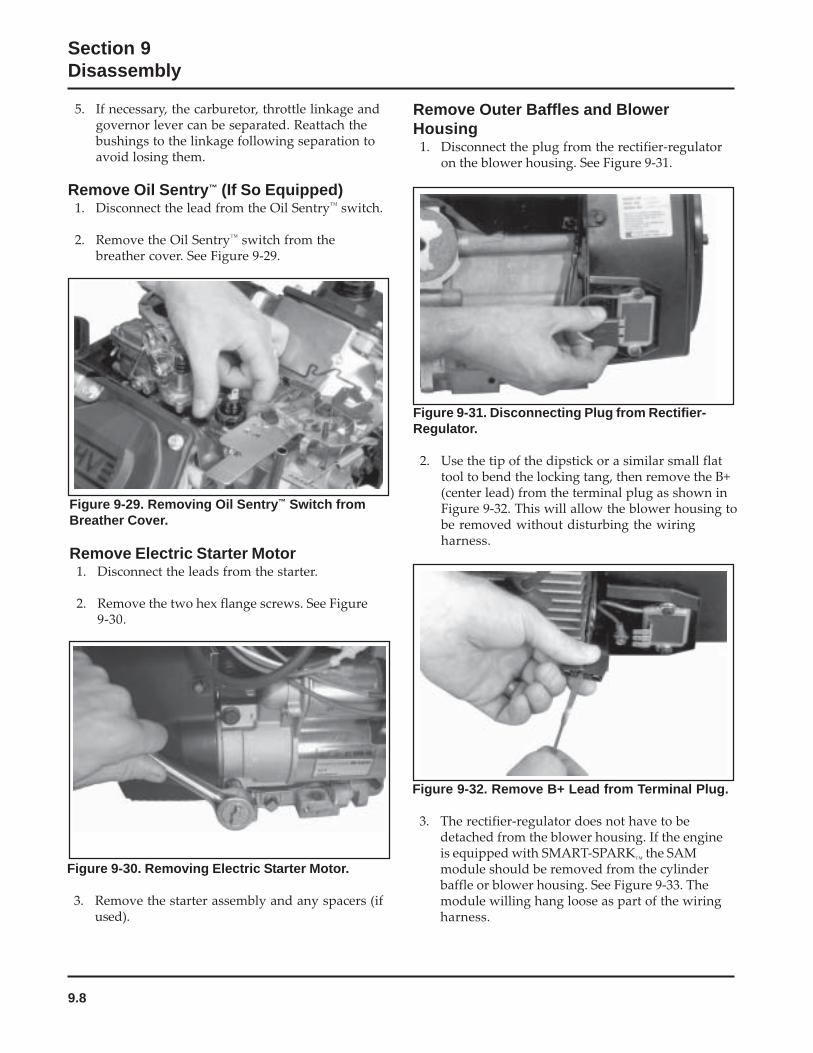
9.8
Section 9Disassembly
Figure 9-32. Remove B+ Lead from Terminal Plug.
3. The rectifier-regulator does not have to bedetached from the blower housing. If the engineis equipped with SMART-SPARK
™ the SAM
module should be removed from the cylinderbaffle or blower housing. See Figure 9-33. Themodule willing hang loose as part of the wiringharness.
Figure 9-30. Removing Electric Starter Motor.
3. Remove the starter assembly and any spacers (ifused).
Figure 9-29. Removing Oil Sentry™ Switch fromBreather Cover.
Remove Electric Starter Motor1. Disconnect the leads from the starter.
2. Remove the two hex flange screws. See Figure9-30.
5. If necessary, the carburetor, throttle linkage andgovernor lever can be separated. Reattach thebushings to the linkage following separation toavoid losing them.
Remove Oil Sentry™ (If So Equipped)1. Disconnect the lead from the Oil Sentry™ switch.
2. Remove the Oil Sentry™ switch from thebreather cover. See Figure 9-29.
Figure 9-31. Disconnecting Plug from Rectifier-Regulator.
2. Use the tip of the dipstick or a similar small flattool to bend the locking tang, then remove the B+(center lead) from the terminal plug as shown inFigure 9-32. This will allow the blower housing tobe removed without disturbing the wiringharness.
Remove Outer Baffles and BlowerHousing
1. Disconnect the plug from the rectifier-regulatoron the blower housing. See Figure 9-31.
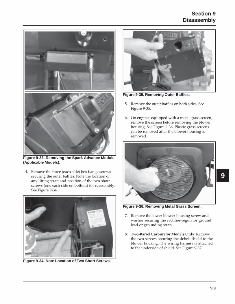
9.9
Section 9Disassembly
9
Figure 9-33. Removing the Spark Advance Module(Applicable Models).
4. Remove the three (each side) hex flange screwssecuring the outer baffles. Note the location ofany lifting strap and position of the two shortscrews (one each side on bottom) for reassembly.See Figure 9-34.
Figure 9-35. Removing Outer Baffles.
5. Remove the outer baffles on both sides. SeeFigure 9-35.
6. On engines equipped with a metal grass screen,remove the screen before removing the blowerhousing. See Figure 9-36. Plastic grass screenscan be removed after the blower housing isremoved.
Figure 9-34. Note Location of Two Short Screws.
Figure 9-36. Removing Metal Grass Screen.
7. Remove the lower blower housing screw andwasher securing the rectifier-regulator groundlead or grounding strap.
8. Two-Barrel Carburetor Models Only: Removethe two screws securing the debris shield to theblower housing. The wiring harness is attachedto the underside of shield. See Figure 9-37.
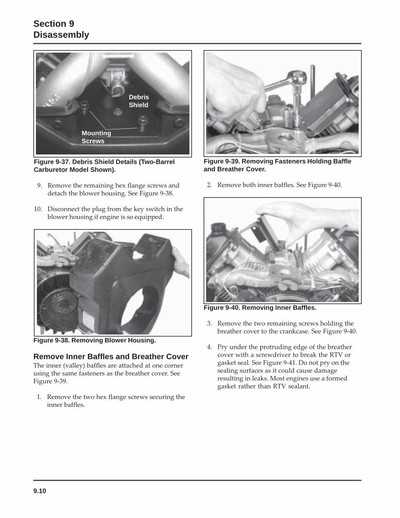
9.10
Section 9Disassembly
Figure 9-39. Removing Fasteners Holding Baffleand Breather Cover.
2. Remove both inner baffles. See Figure 9-40.
Figure 9-40. Removing Inner Baffles.
3. Remove the two remaining screws holding thebreather cover to the crankcase. See Figure 9-40.
4. Pry under the protruding edge of the breathercover with a screwdriver to break the RTV orgasket seal. See Figure 9-41. Do not pry on thesealing surfaces as it could cause damageresulting in leaks. Most engines use a formedgasket rather than RTV sealant.
Figure 9-38. Removing Blower Housing.
Remove Inner Baffles and Breather CoverThe inner (valley) baffles are attached at one cornerusing the same fasteners as the breather cover. SeeFigure 9-39.
1. Remove the two hex flange screws securing theinner baffles.
Figure 9-37. Debris Shield Details (Two-BarrelCarburetor Model Shown).
9. Remove the remaining hex flange screws anddetach the blower housing. See Figure 9-38.
10. Disconnect the plug from the key switch in theblower housing if engine is so equipped.
MountingScrews
DebrisShield
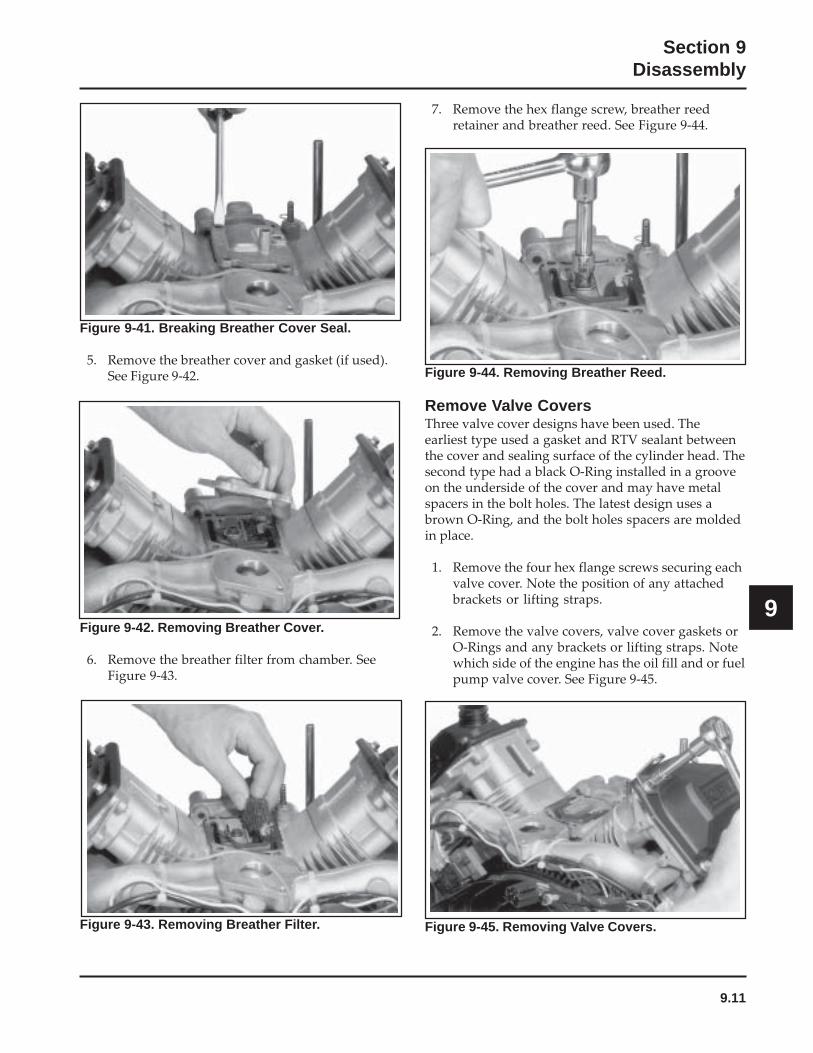
9.11
Section 9Disassembly
9
7. Remove the hex flange screw, breather reedretainer and breather reed. See Figure 9-44.
Figure 9-44. Removing Breather Reed.
Remove Valve CoversThree valve cover designs have been used. Theearliest type used a gasket and RTV sealant betweenthe cover and sealing surface of the cylinder head. Thesecond type had a black O-Ring installed in a grooveon the underside of the cover and may have metalspacers in the bolt holes. The latest design uses abrown O-Ring, and the bolt holes spacers are moldedin place.
1. Remove the four hex flange screws securing eachvalve cover. Note the position of any attachedbrackets or lifting straps.
2. Remove the valve covers, valve cover gaskets orO-Rings and any brackets or lifting straps. Notewhich side of the engine has the oil fill and or fuelpump valve cover. See Figure 9-45.
Figure 9-41. Breaking Breather Cover Seal.
5. Remove the breather cover and gasket (if used).See Figure 9-42.
Figure 9-42. Removing Breather Cover.
6. Remove the breather filter from chamber. SeeFigure 9-43.
Figure 9-45. Removing Valve Covers.Figure 9-43. Removing Breather Filter.
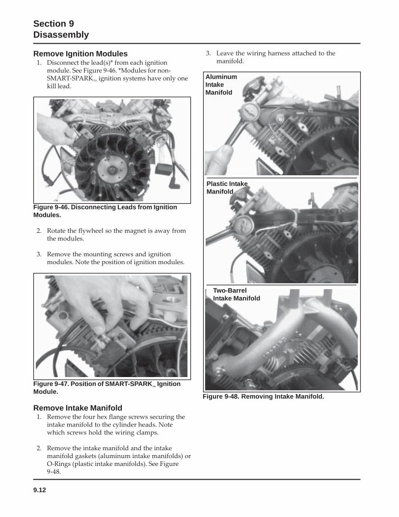
9.12
Section 9Disassembly
Figure 9-46. Disconnecting Leads from IgnitionModules.
2. Rotate the flywheel so the magnet is away fromthe modules.
3. Remove the mounting screws and ignitionmodules. Note the position of ignition modules.
Figure 9-47. Position of SMART-SPARK™ Ignition
Module.
Remove Intake Manifold1. Remove the four hex flange screws securing the
intake manifold to the cylinder heads. Notewhich screws hold the wiring clamps.
2. Remove the intake manifold and the intakemanifold gaskets (aluminum intake manifolds) orO-Rings (plastic intake manifolds). See Figure9-48.
Figure 9-48. Removing Intake Manifold.
AluminumIntakeManifold
Plastic IntakeManifold
Remove Ignition Modules1. Disconnect the lead(s)* from each ignition
module. See Figure 9-46. *Modules for non-SMART-SPARK
™ ignition systems have only one
kill lead.
3. Leave the wiring harness attached to themanifold.
Two-BarrelIntake Manifold
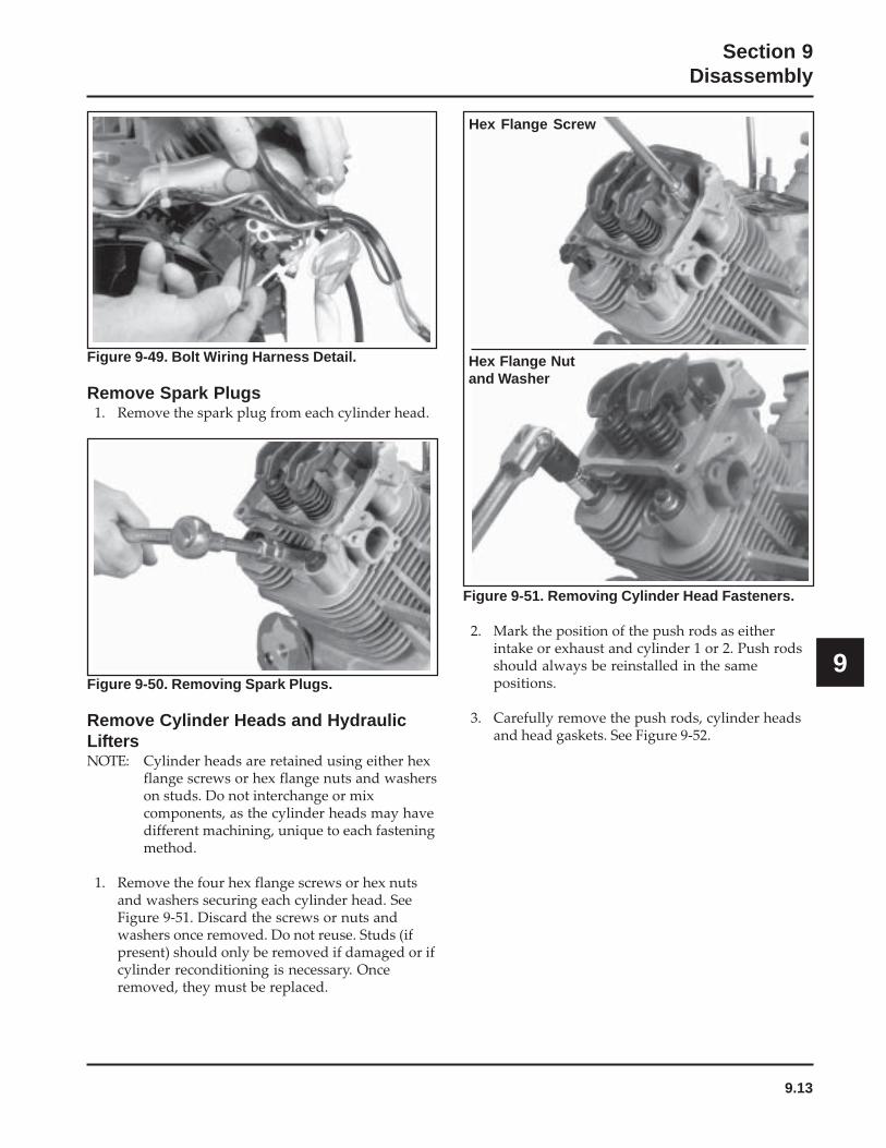
9.13
Section 9Disassembly
9
Figure 9-51. Removing Cylinder Head Fasteners.
2. Mark the position of the push rods as eitherintake or exhaust and cylinder 1 or 2. Push rodsshould always be reinstalled in the samepositions.
3. Carefully remove the push rods, cylinder headsand head gaskets. See Figure 9-52.
Figure 9-50. Removing Spark Plugs.
Remove Cylinder Heads and HydraulicLiftersNOTE: Cylinder heads are retained using either hex
flange screws or hex flange nuts and washerson studs. Do not interchange or mixcomponents, as the cylinder heads may havedifferent machining, unique to each fasteningmethod.
1. Remove the four hex flange screws or hex nutsand washers securing each cylinder head. SeeFigure 9-51. Discard the screws or nuts andwashers once removed. Do not reuse. Studs (ifpresent) should only be removed if damaged or ifcylinder reconditioning is necessary. Onceremoved, they must be replaced.
Hex Flange Screw
Hex Flange Nutand Washer
Figure 9-49. Bolt Wiring Harness Detail.
Remove Spark Plugs1. Remove the spark plug from each cylinder head.
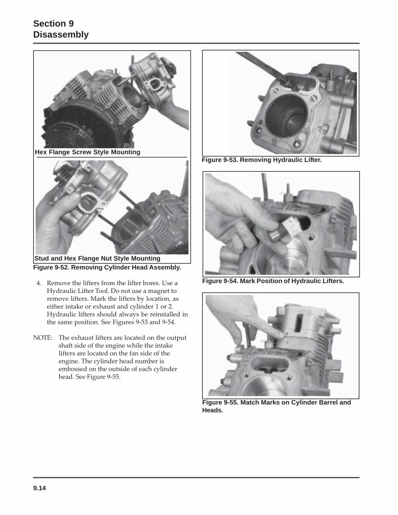
9.14
Section 9Disassembly
Figure 9-53. Removing Hydraulic Lifter.
Figure 9-52. Removing Cylinder Head Assembly.
4. Remove the lifters from the lifter bores. Use aHydraulic Lifter Tool. Do not use a magnet toremove lifters. Mark the lifters by location, aseither intake or exhaust and cylinder 1 or 2.Hydraulic lifters should always be reinstalled inthe same position. See Figures 9-53 and 9-54.
NOTE: The exhaust lifters are located on the outputshaft side of the engine while the intakelifters are located on the fan side of theengine. The cylinder head number isembossed on the outside of each cylinderhead. See Figure 9-55.
Figure 9-54. Mark Position of Hydraulic Lifters.
Figure 9-55. Match Marks on Cylinder Barrel andHeads.
Hex Flange Screw Style Mounting
Stud and Hex Flange Nut Style Mounting
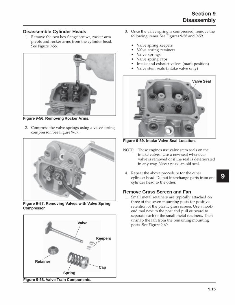
9.15
Section 9Disassembly
9
Figure 9-58. Valve Train Components.
Figure 9-56. Removing Rocker Arms.
2. Compress the valve springs using a valve springcompressor. See Figure 9-57.
Figure 9-57. Removing Valves with Valve SpringCompressor.
Disassemble Cylinder Heads1. Remove the two hex flange screws, rocker arm
pivots and rocker arms from the cylinder head.See Figure 9-56.
3. Once the valve spring is compressed, remove thefollowing items. See Figures 9-58 and 9-59.
• Valve spring keepers• Valve spring retainers• Valve springs• Valve spring caps• Intake and exhaust valves (mark position)• Valve stem seals (intake valve only)
Valve
Retainer
Spring
Keepers
Cap
Valve Seal
Figure 9-59. Intake Valve Seal Location.
NOTE: These engines use valve stem seals on theintake valves. Use a new seal whenevervalve is removed or if the seal is deterioratedin any way. Never reuse an old seal.
4. Repeat the above procedure for the othercylinder head. Do not interchange parts from onecylinder head to the other.
Remove Grass Screen and Fan1. Small metal retainers are typically attached on
three of the seven mounting posts for positiveretention of the plastic grass screen. Use a hook-end tool next to the post and pull outward toseparate each of the small metal retainers. Thenunsnap the fan from the remaining mountingposts. See Figure 9-60.

9.16
Section 9Disassembly
Figure 9-60. Removing Plastic Type Grass Screen.
2. Remove the four hex flange screws and fan. SeeFigure 9-61.
Figure 9-61. Removing Fan.
Remove Flywheel1. Use a flywheel strap wrench or holding tool (see
Section 2) to hold the flywheel and loosen the hexflange screw securing the flywheel to thecrankshaft. See Figure 9-62.
NOTE: Always use a flywheel strap wrench orholding tool to hold the flywheel whenloosening or tightening the flywheelscrew. Do not use any type of bar orwedge to hold the flywheel. Use of suchtools could cause the flywheel to becomecracked or damaged.
Figure 9-62. Removing Flywheel Fastener UsingStrap Wrench.
2. Remove the hex flange screw and washer.
3. Use a puller to remove the flywheel from thecrankshaft. See Figure 9-63.
NOTE: Always use a flywheel puller to removethe flywheel from the crankshaft. Donot strike the crankshaft or flywheel, asthese parts could become cracked ordamaged. Striking the puller orcrankshaft can cause the crank gear tomove, affecting the crankshaft end play.
Figure 9-63. Removing Flywheel with a Puller.
4. Remove the woodruff key from the crankshaft.
Remove Stator and Backing Plates1. Remove the four hex flange screws securing the
backing plates and stator wire bracket (ifequipped). See Figure 9-64. Remove the backingplates and stator wire bracket.
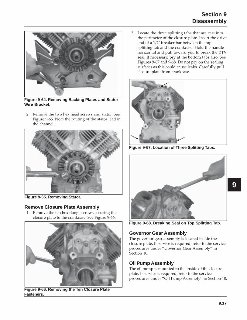
9.17
Section 9Disassembly
9
Figure 9-68. Breaking Seal on Top Splitting Tab.
Governor Gear AssemblyThe governor gear assembly is located inside theclosure plate. If service is required, refer to the serviceprocedures under ‘‘Governor Gear Assembly’’ inSection 10.
Oil Pump AssemblyThe oil pump is mounted to the inside of the closureplate. If service is required, refer to the serviceprocedures under ‘‘Oil Pump Assembly’’ in Section 10.
Figure 9-64. Removing Backing Plates and StatorWire Bracket.
2. Remove the two hex head screws and stator. SeeFigure 9-65. Note the routing of the stator lead inthe channel.
Figure 9-65. Removing Stator.
Remove Closure Plate Assembly1. Remove the ten hex flange screws securing the
closure plate to the crankcase. See Figure 9-66.
2. Locate the three splitting tabs that are cast intothe perimeter of the closure plate. Insert the driveend of a 1/2" breaker bar between the topsplitting tab and the crankcase. Hold the handlehorizontal and pull toward you to break the RTVseal. If necessary, pry at the bottom tabs also. SeeFigures 9-67 and 9-68. Do not pry on the sealingsurfaces as this could cause leaks. Carefully pullclosure plate from crankcase.
Figure 9-66. Removing the Ten Closure PlateFasteners.
Figure 9-67. Location of Three Splitting Tabs.
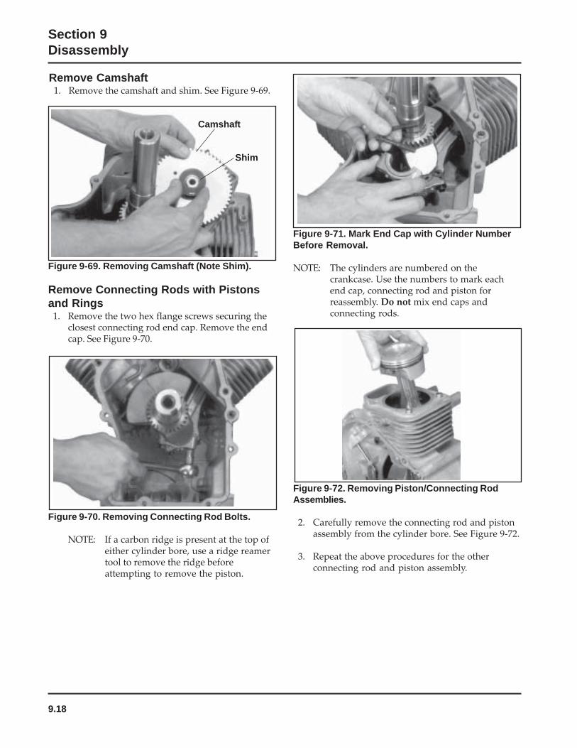
9.18
Section 9Disassembly
Figure 9-70. Removing Connecting Rod Bolts.
NOTE: If a carbon ridge is present at the top ofeither cylinder bore, use a ridge reamertool to remove the ridge beforeattempting to remove the piston.
Figure 9-69. Removing Camshaft (Note Shim).
Remove Connecting Rods with Pistonsand Rings
1. Remove the two hex flange screws securing theclosest connecting rod end cap. Remove the endcap. See Figure 9-70.
Figure 9-71. Mark End Cap with Cylinder NumberBefore Removal.
NOTE: The cylinders are numbered on thecrankcase. Use the numbers to mark eachend cap, connecting rod and piston forreassembly. Do not mix end caps andconnecting rods.
Figure 9-72. Removing Piston/Connecting RodAssemblies.
2. Carefully remove the connecting rod and pistonassembly from the cylinder bore. See Figure 9-72.
3. Repeat the above procedures for the otherconnecting rod and piston assembly.
Remove Camshaft1. Remove the camshaft and shim. See Figure 9-69.
Camshaft
Shim
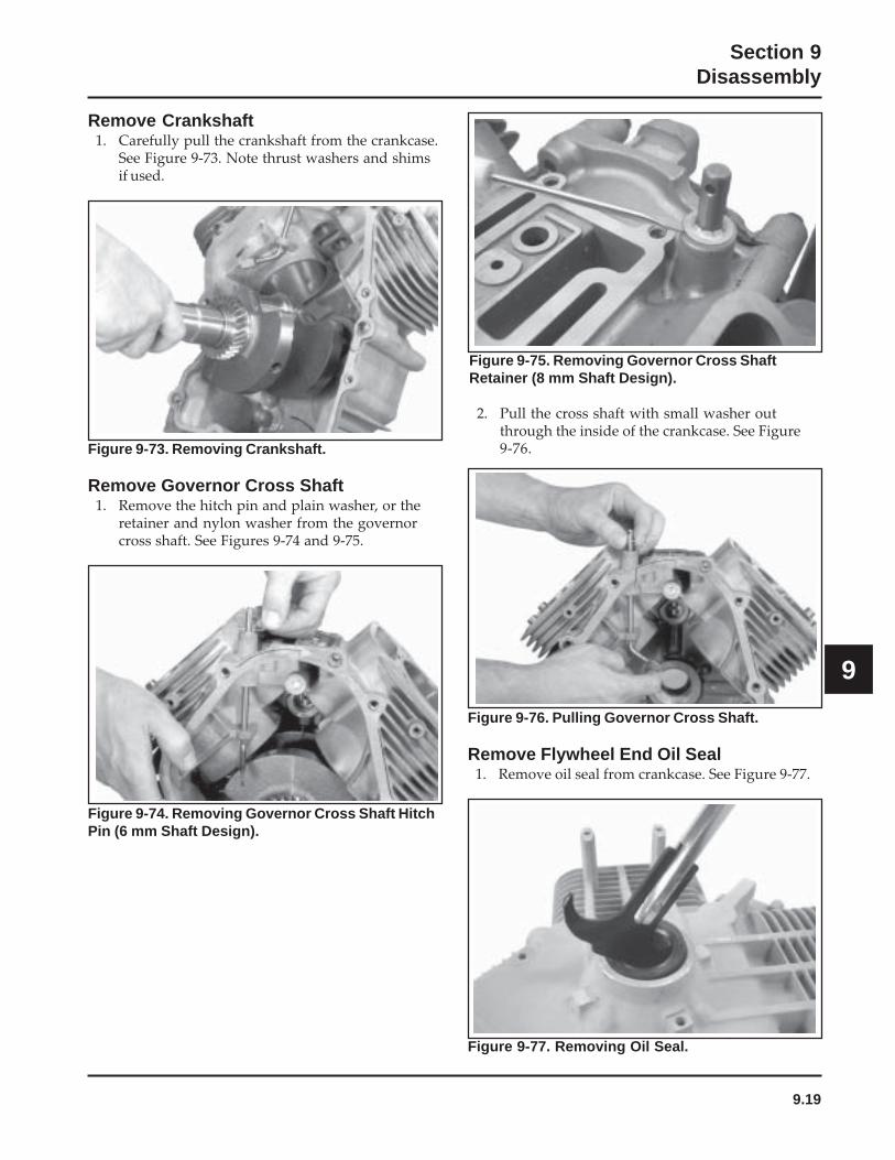
9.19
Section 9Disassembly
9
Figure 9-73. Removing Crankshaft.
Remove Governor Cross Shaft1. Remove the hitch pin and plain washer, or the
retainer and nylon washer from the governorcross shaft. See Figures 9-74 and 9-75.
Remove Crankshaft1. Carefully pull the crankshaft from the crankcase.
See Figure 9-73. Note thrust washers and shimsif used.
Figure 9-75. Removing Governor Cross ShaftRetainer (8 mm Shaft Design).
2. Pull the cross shaft with small washer outthrough the inside of the crankcase. See Figure9-76.
Figure 9-74. Removing Governor Cross Shaft HitchPin (6 mm Shaft Design).
Figure 9-76. Pulling Governor Cross Shaft.
Remove Flywheel End Oil Seal1. Remove oil seal from crankcase. See Figure 9-77.
Figure 9-77. Removing Oil Seal.
10.1
Section 10Inspection and Reconditioning
10
Section 10Inspection and Reconditioning
This section covers the operation, inspection, andrepair/reconditioning of major internal enginecomponents. The following components are notcovered in this section. They are covered in sections oftheir own:
Air Cleaner, Section 4Carburetor & External Governor, Section 5Ignition, Charging & Electric Starter, Section 8
Clean all parts thoroughly. Only clean parts can beaccurately inspected and gauged for wear or damage.There are many commercially available cleaners thatwill quickly remove grease, oil, and grime fromengine parts. When such a cleaner is used, follow themanufacturer’s instructions and safety precautionscarefully. Make sure all traces of the cleaner areremoved before the engine is reassembled and placedinto operation. Even small amounts of these cleanerscan quickly break down the lubricating properties ofengine oil.
Use an aerosol gasket remover, paint stripper, orlacquer thinner to remove any old sealant. Apply thesolvent, allow time for it to work, and then brush thesurface with a brass wire brush. After the old sealantis removed, clean the surface with isopropyl alcohol,lacquer thinner, or aerosol electrical contact cleaner.Do not scrape the surfaces, as any scratches, nicks, orburrs can result in leaks. See Service Bulletin 252 forfurther information.
Refer to A Guide to Engine Rebuilding (TP-2150-A)for additional information. Measurement Guide(TP-2159-B) and Engine Inspection Data Record(TP-2435) are also available; use these to recordinspection results.
Automatic Compression Release (ACR)Some engines are equipped with the optionalAutomatic Compression Release (ACR) mechanism.The ACR lowers compression at cranking speeds tomake starting easier.
OperationThe ACR mechanism consists of a flyweight, springand pivoting control pin assembly attached to the gearon the camshaft. At cranking speeds (700 RPM orlower), the control pin protrudes above the exhaustcam lobe. This pushes the exhaust valve off its seatduring the first part of the compression stroke. Thereduced compression results in an effectivecompression ratio of about 2:1 during cranking.
After starting, engine speed increases to over 700RPM, and centrifugal force overcomes the force of theflyweight spring. The flyweight moves outward,pulling the arm of the control pin, so it pivots into the‘‘run’’ position. The control pin no longer has anyeffect on the exhaust valve and the engine operates atfull power.
When the engine is stopped, the spring returns theflyweight lever and control pin assembly to thecompression release position ready for the next start.
Camshaft
Inspection and ServiceCheck the lobes of the camshaft for wear or damage.See Section 1 for minimum lift specifications. Inspectthe cam gear for badly worn, chipped or missing teeth.Replacement of the camshaft will be necessary if anyof these conditions exist.
Crankshaft
Inspection and ServiceInspect the gear teeth of the crankshaft. If the teeth arebadly worn, chipped, or some are missing,replacement of the crankshaft will be necessary.
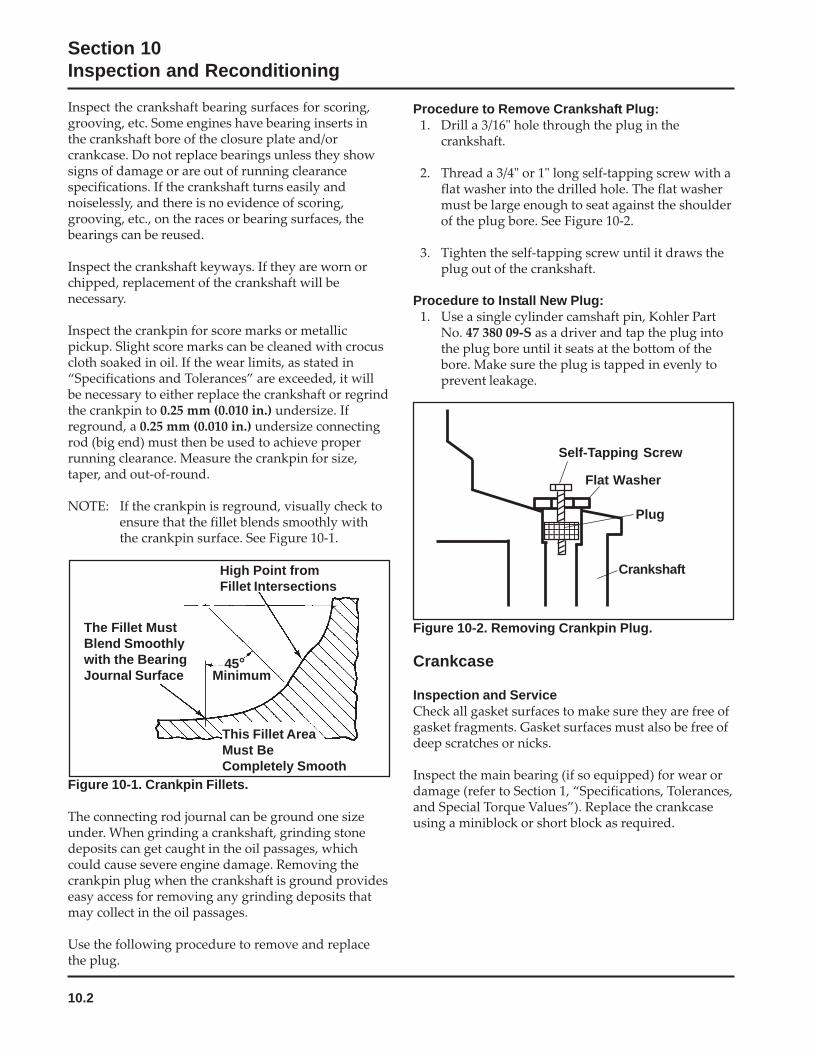
10.2
Section 10Inspection and Reconditioning
Inspect the crankshaft bearing surfaces for scoring,grooving, etc. Some engines have bearing inserts inthe crankshaft bore of the closure plate and/orcrankcase. Do not replace bearings unless they showsigns of damage or are out of running clearancespecifications. If the crankshaft turns easily andnoiselessly, and there is no evidence of scoring,grooving, etc., on the races or bearing surfaces, thebearings can be reused.
Inspect the crankshaft keyways. If they are worn orchipped, replacement of the crankshaft will benecessary.
Inspect the crankpin for score marks or metallicpickup. Slight score marks can be cleaned with crocuscloth soaked in oil. If the wear limits, as stated in“Specifications and Tolerances” are exceeded, it willbe necessary to either replace the crankshaft or regrindthe crankpin to 0.25 mm (0.010 in.) undersize. Ifreground, a 0.25 mm (0.010 in.) undersize connectingrod (big end) must then be used to achieve properrunning clearance. Measure the crankpin for size,taper, and out-of-round.
NOTE: If the crankpin is reground, visually check toensure that the fillet blends smoothly withthe crankpin surface. See Figure 10-1.
Procedure to Remove Crankshaft Plug:1. Drill a 3/16" hole through the plug in the
crankshaft.
2. Thread a 3/4" or 1" long self-tapping screw with aflat washer into the drilled hole. The flat washermust be large enough to seat against the shoulderof the plug bore. See Figure 10-2.
3. Tighten the self-tapping screw until it draws theplug out of the crankshaft.
Procedure to Install New Plug:1. Use a single cylinder camshaft pin, Kohler Part
No. 47 380 09-S as a driver and tap the plug intothe plug bore until it seats at the bottom of thebore. Make sure the plug is tapped in evenly toprevent leakage.
45°
High Point fromFillet Intersections
This Fillet AreaMust BeCompletely Smooth
Minimum
The Fillet MustBlend Smoothlywith the BearingJournal Surface
Figure 10-1. Crankpin Fillets.
The connecting rod journal can be ground one sizeunder. When grinding a crankshaft, grinding stonedeposits can get caught in the oil passages, whichcould cause severe engine damage. Removing thecrankpin plug when the crankshaft is ground provideseasy access for removing any grinding deposits thatmay collect in the oil passages.
Use the following procedure to remove and replacethe plug.
Figure 10-2. Removing Crankpin Plug.
Crankcase
Inspection and ServiceCheck all gasket surfaces to make sure they are free ofgasket fragments. Gasket surfaces must also be free ofdeep scratches or nicks.
Inspect the main bearing (if so equipped) for wear ordamage (refer to Section 1, “Specifications, Tolerances,and Special Torque Values”). Replace the crankcaseusing a miniblock or short block as required.
Flat Washer
Self-Tapping Screw
12345678123456781234567812345678
Plug
Crankshaft
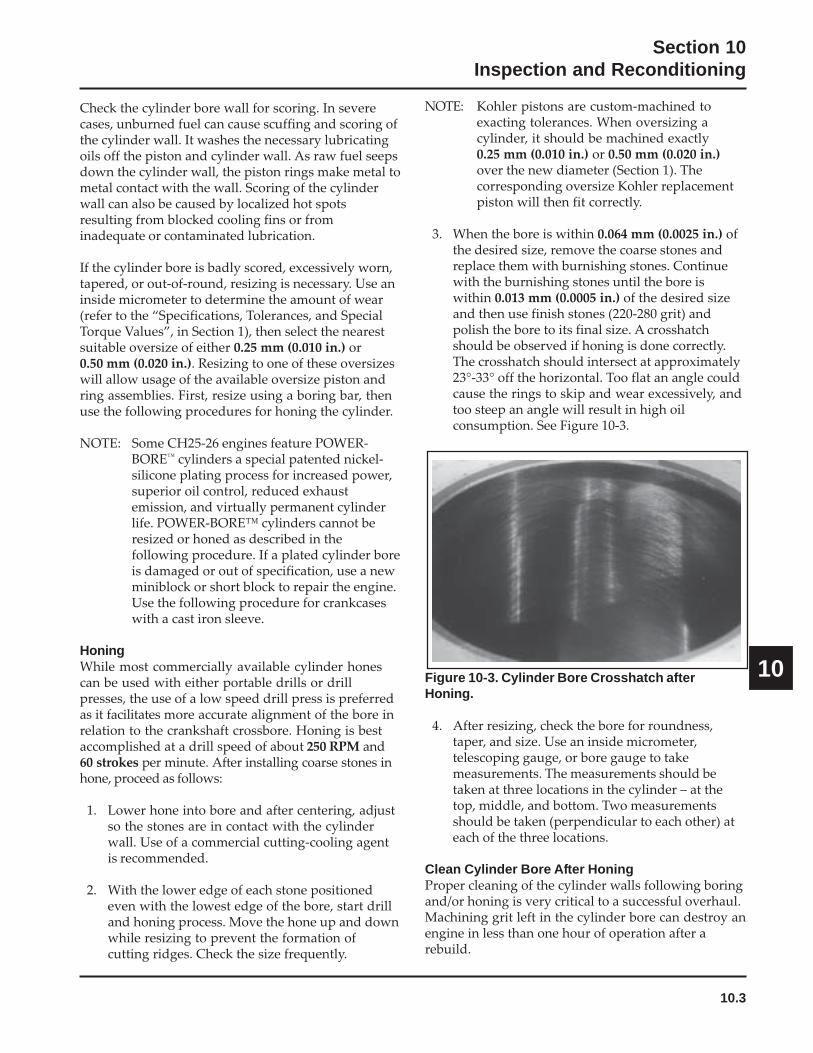
10.3
Section 10Inspection and Reconditioning
10
Check the cylinder bore wall for scoring. In severecases, unburned fuel can cause scuffing and scoring ofthe cylinder wall. It washes the necessary lubricatingoils off the piston and cylinder wall. As raw fuel seepsdown the cylinder wall, the piston rings make metal tometal contact with the wall. Scoring of the cylinderwall can also be caused by localized hot spotsresulting from blocked cooling fins or frominadequate or contaminated lubrication.
If the cylinder bore is badly scored, excessively worn,tapered, or out-of-round, resizing is necessary. Use aninside micrometer to determine the amount of wear(refer to the “Specifications, Tolerances, and SpecialTorque Values”, in Section 1), then select the nearestsuitable oversize of either 0.25 mm (0.010 in.) or0.50 mm (0.020 in.). Resizing to one of these oversizeswill allow usage of the available oversize piston andring assemblies. First, resize using a boring bar, thenuse the following procedures for honing the cylinder.
NOTE: Some CH25-26 engines feature POWER-BORE™ cylinders a special patented nickel-silicone plating process for increased power,superior oil control, reduced exhaustemission, and virtually permanent cylinderlife. POWER-BORE™ cylinders cannot beresized or honed as described in thefollowing procedure. If a plated cylinder boreis damaged or out of specification, use a newminiblock or short block to repair the engine.Use the following procedure for crankcaseswith a cast iron sleeve.
HoningWhile most commercially available cylinder honescan be used with either portable drills or drillpresses, the use of a low speed drill press is preferredas it facilitates more accurate alignment of the bore inrelation to the crankshaft crossbore. Honing is bestaccomplished at a drill speed of about 250 RPM and60 strokes per minute. After installing coarse stones inhone, proceed as follows:
1. Lower hone into bore and after centering, adjustso the stones are in contact with the cylinderwall. Use of a commercial cutting-cooling agentis recommended.
2. With the lower edge of each stone positionedeven with the lowest edge of the bore, start drilland honing process. Move the hone up and downwhile resizing to prevent the formation ofcutting ridges. Check the size frequently.
Figure 10-3. Cylinder Bore Crosshatch afterHoning.
4. After resizing, check the bore for roundness,taper, and size. Use an inside micrometer,telescoping gauge, or bore gauge to takemeasurements. The measurements should betaken at three locations in the cylinder – at thetop, middle, and bottom. Two measurementsshould be taken (perpendicular to each other) ateach of the three locations.
Clean Cylinder Bore After HoningProper cleaning of the cylinder walls following boringand/or honing is very critical to a successful overhaul.Machining grit left in the cylinder bore can destroy anengine in less than one hour of operation after arebuild.
NOTE: Kohler pistons are custom-machined toexacting tolerances. When oversizing acylinder, it should be machined exactly0.25 mm (0.010 in.) or 0.50 mm (0.020 in.)over the new diameter (Section 1). Thecorresponding oversize Kohler replacementpiston will then fit correctly.
3. When the bore is within 0.064 mm (0.0025 in.) ofthe desired size, remove the coarse stones andreplace them with burnishing stones. Continuewith the burnishing stones until the bore iswithin 0.013 mm (0.0005 in.) of the desired sizeand then use finish stones (220-280 grit) andpolish the bore to its final size. A crosshatchshould be observed if honing is done correctly.The crosshatch should intersect at approximately23°-33° off the horizontal. Too flat an angle couldcause the rings to skip and wear excessively, andtoo steep an angle will result in high oilconsumption. See Figure 10-3.
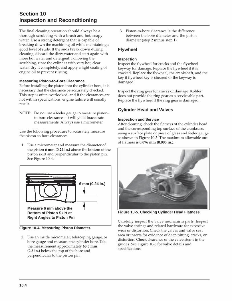
10.4
Section 10Inspection and Reconditioning
The final cleaning operation should always be athorough scrubbing with a brush and hot, soapywater. Use a strong detergent that is capable ofbreaking down the machining oil while maintaining agood level of suds. If the suds break down duringcleaning, discard the dirty water and start again withmore hot water and detergent. Following thescrubbing, rinse the cylinder with very hot, clearwater, dry it completely, and apply a light coating ofengine oil to prevent rusting.
Measuring Piston-to-Bore ClearanceBefore installing the piston into the cylinder bore, it isnecessary that the clearance be accurately checked.This step is often overlooked, and if the clearances arenot within specifications, engine failure will usuallyresult.
NOTE: Do not use a feeler gauge to measure piston-to-bore clearance – it will yield inaccuratemeasurements. Always use a micrometer.
Use the following procedure to accurately measurethe piston-to-bore clearance:
1. Use a micrometer and measure the diameter ofthe piston 6 mm (0.24 in.) above the bottom of thepiston skirt and perpendicular to the piston pin.See Figure 10-4.
3. Piston-to-bore clearance is the differencebetween the bore diameter and the pistondiameter (step 2 minus step 1).
Flywheel
InspectionInspect the flywheel for cracks and the flywheelkeyway for damage. Replace the flywheel if it iscracked. Replace the flywheel, the crankshaft, and thekey if flywheel key is sheared or the keyway isdamaged.
Inspect the ring gear for cracks or damage. Kohlerdoes not provide the ring gear as a serviceable part.Replace the flywheel if the ring gear is damaged.
Cylinder Head and Valves
Inspection and ServiceAfter cleaning, check the flatness of the cylinder headand the corresponding top surface of the crankcase,using a surface plate or piece of glass and feeler gaugeas shown in Figure 10-5. The maximum allowable outof flatness is 0.076 mm (0.003 in.).
6 mm (0.24 in.)
Measure 6 mm above theBottom of Piston Skirt atRight Angles to Piston Pin
Figure 10-4. Measuring Piston Diameter.
2. Use an inside micrometer, telescoping gauge, orbore gauge and measure the cylinder bore. Takethe measurement approximately 63.5 mm(2.5 in.) below the top of the bore andperpendicular to the piston pin.
Figure 10-5. Checking Cylinder Head Flatness.
Carefully inspect the valve mechanism parts. Inspectthe valve springs and related hardware for excessivewear or distortion. Check the valves and valve seatarea or inserts for evidence of deep pitting, cracks, ordistortion. Check clearance of the valve stems in theguides. See Figure 10-6 for valve details andspecifications.
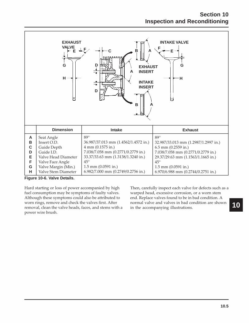
10.5
Section 10Inspection and Reconditioning
10
EXHAUSTVALVE
E
G
F
H
D
D
C
A
B A
B AF
E
G
H
INTAKE VALVE
EXHAUSTINSERT
INTAKEINSERT
ABCDEFGH
Seat AngleInsert O.D.Guide DepthGuide I.D.Valve Head DiameterValve Face AngleValve Margin (Min.)Valve Stem Diameter
Dimension
89°36.987/37.013 mm (1.4562/1.4572 in.)4 mm (0.1575 in.)7.038/7.058 mm (0.2771/0.2779 in.)33.37/33.63 mm (1.3138/1.3240 in.)45°1.5 mm (0.0591 in.)6.982/7.000 mm (0.2749/0.2756 in.)
Intake Exhaust
89°32.987/33.013 mm (1.2987/1.2997 in.)6.5 mm (0.2559 in.)7.038/7.058 mm (0.2771/0.2779 in.)29.37/29.63 mm (1.1563/1.1665 in.)45°1.5 mm (0.0591 in.)6.970/6.988 mm (0.2744/0.2751 in.)
Figure 10-6. Valve Details.
Hard starting or loss of power accompanied by highfuel consumption may be symptoms of faulty valves.Although these symptoms could also be attributed toworn rings, remove and check the valves first. Afterremoval, clean the valve heads, faces, and stems with apower wire brush.
Then, carefully inspect each valve for defects such as awarped head, excessive corrosion, or a worn stemend. Replace valves found to be in bad condition. Anormal valve and valves in bad condition are shownin the accompanying illustrations.
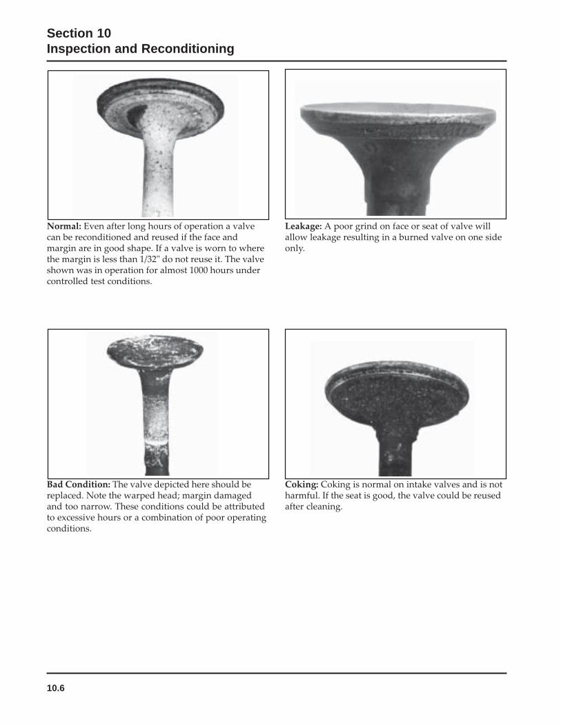
10.6
Section 10Inspection and Reconditioning
Normal: Even after long hours of operation a valvecan be reconditioned and reused if the face andmargin are in good shape. If a valve is worn to wherethe margin is less than 1/32" do not reuse it. The valveshown was in operation for almost 1000 hours undercontrolled test conditions.
Bad Condition: The valve depicted here should bereplaced. Note the warped head; margin damagedand too narrow. These conditions could be attributedto excessive hours or a combination of poor operatingconditions.
Leakage: A poor grind on face or seat of valve willallow leakage resulting in a burned valve on one sideonly.
Coking: Coking is normal on intake valves and is notharmful. If the seat is good, the valve could be reusedafter cleaning.

10.7
Section 10Inspection and Reconditioning
10
Excessive Combustion Temperatures: The whitedeposits seen here indicate very high combustiontemperatures, usually due to a lean fuel mixture.
Gum: Gum deposits usually result from using stalegasoline. Gum is a prevalent cause of valve sticking.The cure is to ream the valve guides and clean orreplace the valves, depending on their condition.
Stem Corrosion: Moisture in fuel or fromcondensation are the most common causes of valvestem corrosion. Condensation occurs from improperpreservation during storage and when engine isrepeatedly stopped before it has a chance to reachnormal operating temperatures. Replace corrodedvalves.
Overheating: An exhaust valve subject tooverheating will have a dark discoloration in the areaabove the valve guide. Worn guides and faulty valvesprings may cause this condition. Also check forclogged air intake, and blocked fins when thiscondition is noted.

10.8
Section 10Inspection and Reconditioning
Valve GuidesIf a valve guide is worn beyond specifications, it willnot guide the valve in a straight line. This may result inburnt valve faces or seats, loss of compression, andexcessive oil consumption.
To check valve guide-to-valve stem clearance,thoroughly clean the valve guide and, using a split-ballgauge, measure the inside diameter of the guide. Then,using an outside micrometer, measure the diameter ofthe valve stem at several points on the stem where itmoves in the valve guide. Use the largest stem diameterto calculate the clearance by subtracting the stemdiameter from the guide diameter. If the intakeclearance exceeds 0.038/0.076 mm (0.0015/0.0030 in.)or the exhaust clearance exceeds 0.050/0.088 mm(0.0020/0.0035 in.), determine whether the valve stemor guide is responsible for the excessive clearance.
The maximum (I.D.) wear on the intake valve guide is7.134 mm (0.2809 in.) while 7.159 mm (0.2819 in.) is themaximum allowed on the exhaust guide. The guidesare not removable but can be reamed 0.25 mm(0.010 in.) oversize. Valves with 0.25 mm oversizestems must then be used.
If the guides are within limits but the valve stems areworn beyond limits, install new valves.
Valve Seat InsertsHardened steel alloy intake and exhaust valve seatinserts are press fitted into the cylinder head. Theinserts are not replaceable but can be reconditioned ifnot too badly pitted or distorted. If cracked or badlywarped, the cylinder head should be replaced.
Recondition the valve seat inserts following theinstructions provided with the valve seat cutter beingused. A typical cutter is shown in Figure 10-7. The finalcut should be made with an 89° cutter as specified forthe valve seat angle in Figure 10-6. Cutting the proper45° valve face angle as specified in Figure 10-6, and theproper valve seat angle (44.5°, half of the full 89° angle),will achieve the desired 0.5° (1.0° full cut) interferenceangle where the maximum pressure occurs on theoutside diameters of the valve face and seat.
Figure 10-7. Typical Valve Seat Cutter.
Lapping ValvesReground or new valves must be lapped in, to provideproper fit. Use a hand valve grinder with a suctioncup for final lapping. Lightly coat the valve face with a“fine” grade of grinding compound, then rotate thevalve on its seat with the grinder. Continue grindinguntil a smooth surface is obtained on the seat and onthe valve face. Thoroughly clean the cylinder head insoap and hot water to remove all traces of grindingcompound. After drying the cylinder head, apply alight coating of SAE 10 oil to prevent rusting.
Intake Valve Stem SealThese engines use valve stem seals on the intakevalves. Always use a new seal when the valves areremoved from the cylinder head. The seals should alsobe replaced if deteriorated or damaged in any way.Never reuse an old seal.
Pistons and Rings
InspectionScuffing and scoring of pistons and cylinder wallsoccurs when internal engine temperatures approachthe welding point of the piston. Temperatures highenough to do this are created by friction, which isusually attributed to improper lubrication and/oroverheating of the engine.
Normally, very little wear takes place in the pistonboss-piston pin area. If the original piston andconnecting rod can be reused after new rings areinstalled, the original pin can also be reused but newpiston pin retainers are required. The piston pin isincluded as part of the piston assembly – if the pinboss in the piston or the pin are worn or damaged, anew piston assembly is required.
Valve Seat Cutter
Pilot
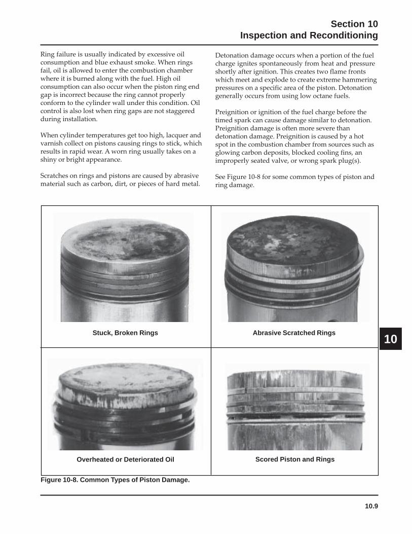
10.9
Section 10Inspection and Reconditioning
10
Ring failure is usually indicated by excessive oilconsumption and blue exhaust smoke. When ringsfail, oil is allowed to enter the combustion chamberwhere it is burned along with the fuel. High oilconsumption can also occur when the piston ring endgap is incorrect because the ring cannot properlyconform to the cylinder wall under this condition. Oilcontrol is also lost when ring gaps are not staggeredduring installation.
When cylinder temperatures get too high, lacquer andvarnish collect on pistons causing rings to stick, whichresults in rapid wear. A worn ring usually takes on ashiny or bright appearance.
Scratches on rings and pistons are caused by abrasivematerial such as carbon, dirt, or pieces of hard metal.
Detonation damage occurs when a portion of the fuelcharge ignites spontaneously from heat and pressureshortly after ignition. This creates two flame frontswhich meet and explode to create extreme hammeringpressures on a specific area of the piston. Detonationgenerally occurs from using low octane fuels.
Preignition or ignition of the fuel charge before thetimed spark can cause damage similar to detonation.Preignition damage is often more severe thandetonation damage. Preignition is caused by a hotspot in the combustion chamber from sources such asglowing carbon deposits, blocked cooling fins, animproperly seated valve, or wrong spark plug(s).
See Figure 10-8 for some common types of piston andring damage.
Overheated or Deteriorated Oil Scored Piston and Rings
Abrasive Scratched RingsStuck, Broken Rings
Figure 10-8. Common Types of Piston Damage.
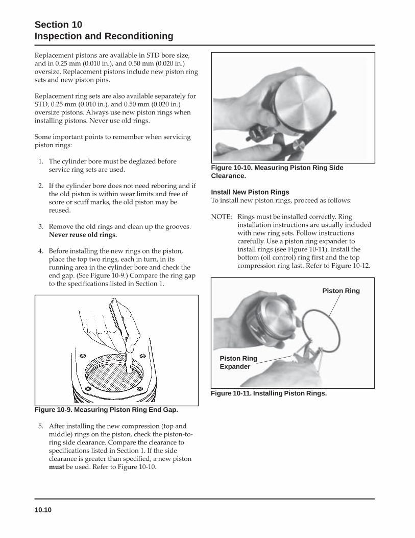
10.10
Section 10Inspection and Reconditioning
Piston Ring
Piston RingExpander
Replacement pistons are available in STD bore size,and in 0.25 mm (0.010 in.), and 0.50 mm (0.020 in.)oversize. Replacement pistons include new piston ringsets and new piston pins.
Replacement ring sets are also available separately forSTD, 0.25 mm (0.010 in.), and 0.50 mm (0.020 in.)oversize pistons. Always use new piston rings wheninstalling pistons. Never use old rings.
Some important points to remember when servicingpiston rings:
1. The cylinder bore must be deglazed beforeservice ring sets are used.
2. If the cylinder bore does not need reboring and ifthe old piston is within wear limits and free ofscore or scuff marks, the old piston may bereused.
3. Remove the old rings and clean up the grooves.Never reuse old rings.
4. Before installing the new rings on the piston,place the top two rings, each in turn, in itsrunning area in the cylinder bore and check theend gap. (See Figure 10-9.) Compare the ring gapto the specifications listed in Section 1.
Figure 10-9. Measuring Piston Ring End Gap.
5. After installing the new compression (top andmiddle) rings on the piston, check the piston-to-ring side clearance. Compare the clearance tospecifications listed in Section 1. If the sideclearance is greater than specified, a new pistonmust be used. Refer to Figure 10-10.
Figure 10-10. Measuring Piston Ring SideClearance.
Install New Piston RingsTo install new piston rings, proceed as follows:
NOTE: Rings must be installed correctly. Ringinstallation instructions are usually includedwith new ring sets. Follow instructionscarefully. Use a piston ring expander toinstall rings (see Figure 10-11). Install thebottom (oil control) ring first and the topcompression ring last. Refer to Figure 10-12.
Figure 10-11. Installing Piston Rings.
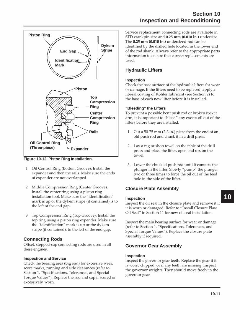
10.11
Section 10Inspection and Reconditioning
10
Figure 10-12. Piston Ring Installation.
1. Oil Control Ring (Bottom Groove): Install theexpander and then the rails. Make sure the endsof expander are not overlapped.
2. Middle Compression Ring (Center Groove):Install the center ring using a piston ringinstallation tool. Make sure the “identification”mark is up or the dykem stripe (if contained) is tothe left of the end gap.
3. Top Compression Ring (Top Groove): Install thetop ring using a piston ring expender. Make surethe “identification” mark is up or the dykemstripe (if contained), to the left of the end gap.
Connecting RodsOffset, stepped-cap connecting rods are used in allthese engines.
Inspection and ServiceCheck the bearing area (big end) for excessive wear,score marks, running and side clearances (refer toSection 1, “Specifications, Tolerances, and SpecialTorque Values”). Replace the rod and cap if scored orexcessively worn.
Service replacement connecting rods are available inSTD crankpin size and 0.25 mm (0.010 in.) undersize.The 0.25 mm (0.010 in.) undersized rod can beidentified by the drilled hole located in the lower endof the rod shank. Always refer to the appropriate partsinformation to ensure that correct replacements areused.
Hydraulic Lifters
InspectionCheck the base surface of the hydraulic lifters for wearor damage. If the lifters need to be replaced, apply aliberal coating of Kohler lubricant (see Section 2) tothe base of each new lifter before it is installed.
“Bleeding” the LiftersTo prevent a possible bent push rod or broken rockerarm, it is important to “bleed” any excess oil out of thelifters before they are installed.
1. Cut a 50-75 mm (2-3 in.) piece from the end of anold push rod and chuck it in a drill press.
2. Lay a rag or shop towel on the table of the drillpress and place the lifter, open end up, on thetowel.
3. Lower the chucked push rod until it contacts theplunger in the lifter. Slowly “pump” the plungertwo or three times to force the oil out of the feedhole in the side of the lifter.
Closure Plate Assembly
InspectionInspect the oil seal in the closure plate and remove it ifit is worn or damaged. Refer to ‘‘Install Closure PlateOil Seal’’ in Section 11 for new oil seal installation.
Inspect the main bearing surface for wear or damage(refer to Section 1, “Specifications, Tolerances, andSpecial Torque Values”). Replace the closure plateassembly if required.
Governor Gear Assembly
InspectionInspect the governor gear teeth. Replace the gear if itis worn, chipped, or if any teeth are missing. Inspectthe governor weights. They should move freely in thegovernor gear.
Piston Ring
End Gap
IdentificationMark
DykemStripe
Piston
TopCompressionRing
CenterCompressionRing
Rails
Expander
Oil Control Ring(Three-piece)

10.12
Section 10Inspection and Reconditioning
Figure 10-13. Removing Governor Gear.
2. Remove the locking tab thrust washer locatedunder the governor gear assembly.
3. Carefully inspect the governor gear shaft andreplace it only if it is damaged. After removingthe damaged shaft, press or lightly tap thereplacement shaft into the closure plate to thedepth shown in Figure 10-14.
Reassembly1. Install the locking tab thrust washer on the
governor gear shaft with the tab down.
2. Position the regulating pin within the governorgear/flyweight assembly and slide both onto thegovernor shaft.
Oil Pump Assembly
Disassembly1. Remove the two hex flange screws.
2. Remove the oil pump assembly from the closureplate.
3. Remove the oil pump rotor.
4. Remove the oil pickup by unhooking the lockingclip, and pulling it free from the oil pump body.
5. If the relief valve is like that shown in Figure10-15, drive out the pin to remove the oil pressurerelief valve piston and spring. Refer to thefollowing inspection and reassembly procedures.
If the relief valve is a one-piece style, staked to theoil pump housing (See Figure 10-16) removalshould not be attempted, nor is internal servicingpossible. If a problem with the relief valve isencountered, the oil pump should be replaced.
DisassemblyThe governor gear must be replaced once it isremoved from the closure plate.
NOTE: The governor gear is held onto the shaft bysmall molded tabs in the gear. When the gearis removed from the shaft, these tabs aredestroyed and the gear must be replaced.Therefore, remove the gear only if absolutelynecessary.
1. Remove the regulating pin and governor gearassembly. See Figure 10-13.
Figure 10-14. Governor Shaft Press Depth.
Gear Shaft
34.0 mm (1.3386 in.)33.5 mm (1.3189 in.)
19.40 mm (0.7638 in.)
Figure 10-15. Oil Pump, Oil Pickup, and Relief Valve(Original Style).
PickupRelief Valve

10.13
Section 10Inspection and Reconditioning
10
3. Install the rotor.
4. Install the oil pump body to the closure plate andsecure with the two hex flange screws. Torquethe hex flange screws as follows:
a. Install fastener into location No. 1 and lightlytighten to position pump.
b. Install fastener into location No. 2 and fullytorque to the recommended value.
c. Torque fastener in location No. 1 to therecommended value.
Figure 10-16. Oil Pump, Oil Pickup, and One-PieceRelief Valve (Later Style).
InspectionInspect the oil pump housing, gear, and rotors fornicks, burrs, wear, or any visible damage. If any partsare worn or damaged, replace the oil pump.
Inspect the oil pressure relief valve piston. It should befree of nicks or burrs.
Check the spring for wear or distortion. The freelength of the spring should be approximately 47.4 mm(1.8 in.). Replace the spring if it is distorted or worn.See Figure 10-17.
PickupRelief Valve
Figure 10-17. Oil Pressure Relief Valve Piston andSpring.
Reassembly1. Install the pressure relief valve piston and spring.
2. Install the oil pickup to the oil pump body.Lubricate the O-Ring with oil and make sure itremains in the groove as the pickup is beinginstalled.
SpringPiston
Roll Pin
First Time Installation:10.7 N·m (95 in. lb.)All Reinstallations: 6.7 N·m (60 in. lb.)
5. After torquing, rotate the gear and check forfreedom of movement. Make sure there is nobinding. If binding occurs, loosen the screws,reposition the pump, retorque the hex flangescrews and recheck the movement.
Oil Pump Torque Sequence
10.1
Section 10Inspection and Reconditioning
10
Section 10Inspection and Reconditioning
This section covers the operation, inspection, andrepair/reconditioning of major internal enginecomponents. The following components are notcovered in this section. They are covered in sections oftheir own:
Air Cleaner, Section 4Carburetor & External Governor, Section 5Ignition, Charging & Electric Starter, Section 8
Clean all parts thoroughly. Only clean parts can beaccurately inspected and gauged for wear or damage.There are many commercially available cleaners thatwill quickly remove grease, oil, and grime fromengine parts. When such a cleaner is used, follow themanufacturer’s instructions and safety precautionscarefully. Make sure all traces of the cleaner areremoved before the engine is reassembled and placedinto operation. Even small amounts of these cleanerscan quickly break down the lubricating properties ofengine oil.
Use an aerosol gasket remover, paint stripper, orlacquer thinner to remove any old sealant. Apply thesolvent, allow time for it to work, and then brush thesurface with a brass wire brush. After the old sealantis removed, clean the surface with isopropyl alcohol,lacquer thinner, or aerosol electrical contact cleaner.Do not scrape the surfaces, as any scratches, nicks, orburrs can result in leaks. See Service Bulletin 252 forfurther information.
Refer to A Guide to Engine Rebuilding (TP-2150-A)for additional information. Measurement Guide(TP-2159-B) and Engine Inspection Data Record(TP-2435) are also available; use these to recordinspection results.
Automatic Compression Release (ACR)Some engines are equipped with the optionalAutomatic Compression Release (ACR) mechanism.The ACR lowers compression at cranking speeds tomake starting easier.
OperationThe ACR mechanism consists of a flyweight, springand pivoting control pin assembly attached to the gearon the camshaft. At cranking speeds (700 RPM orlower), the control pin protrudes above the exhaustcam lobe. This pushes the exhaust valve off its seatduring the first part of the compression stroke. Thereduced compression results in an effectivecompression ratio of about 2:1 during cranking.
After starting, engine speed increases to over 700RPM, and centrifugal force overcomes the force of theflyweight spring. The flyweight moves outward,pulling the arm of the control pin, so it pivots into the‘‘run’’ position. The control pin no longer has anyeffect on the exhaust valve and the engine operates atfull power.
When the engine is stopped, the spring returns theflyweight lever and control pin assembly to thecompression release position ready for the next start.
Camshaft
Inspection and ServiceCheck the lobes of the camshaft for wear or damage.See Section 1 for minimum lift specifications. Inspectthe cam gear for badly worn, chipped or missing teeth.Replacement of the camshaft will be necessary if anyof these conditions exist.
Crankshaft
Inspection and ServiceInspect the gear teeth of the crankshaft. If the teeth arebadly worn, chipped, or some are missing,replacement of the crankshaft will be necessary.

10.14
Section 10Inspection and Reconditioning
Governor Cross Shaft Oil SealIf the governor cross shaft seal is damaged and/orleaks, replace it using the following procedure.
Remove the oil seal from the crankcase and replace itwith a new one. Install the new seal to the depthshown in Figure 10-18 using a seal installer.
2.0 mm (0.0787 in.) Governor CrossShaft Seal
Figure 10-18. Installing Cross Shaft Oil Seal.
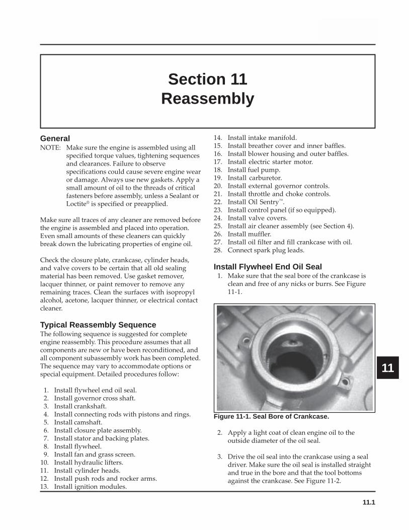
11.1
Section 11Reassembly
11
Section 11Reassembly
GeneralNOTE: Make sure the engine is assembled using all
specified torque values, tightening sequencesand clearances. Failure to observespecifications could cause severe engine wearor damage. Always use new gaskets. Apply asmall amount of oil to the threads of criticalfasteners before assembly, unless a Sealant orLoctite® is specified or preapplied.
Make sure all traces of any cleaner are removed beforethe engine is assembled and placed into operation.Even small amounts of these cleaners can quicklybreak down the lubricating properties of engine oil.
Check the closure plate, crankcase, cylinder heads,and valve covers to be certain that all old sealingmaterial has been removed. Use gasket remover,lacquer thinner, or paint remover to remove anyremaining traces. Clean the surfaces with isopropylalcohol, acetone, lacquer thinner, or electrical contactcleaner.
Typical Reassembly SequenceThe following sequence is suggested for completeengine reassembly. This procedure assumes that allcomponents are new or have been reconditioned, andall component subassembly work has been completed.The sequence may vary to accommodate options orspecial equipment. Detailed procedures follow:
1. Install flywheel end oil seal.2. Install governor cross shaft.3. Install crankshaft.4. Install connecting rods with pistons and rings.5. Install camshaft.6. Install closure plate assembly.7. Install stator and backing plates.8. Install flywheel.9. Install fan and grass screen.
10. Install hydraulic lifters.11. Install cylinder heads.12. Install push rods and rocker arms.13. Install ignition modules.
14. Install intake manifold.15. Install breather cover and inner baffles.16. Install blower housing and outer baffles.17. Install electric starter motor.18. Install fuel pump.19. Install carburetor.20. Install external governor controls.21. Install throttle and choke controls.22. Install Oil Sentry™.23. Install control panel (if so equipped).24. Install valve covers.25. Install air cleaner assembly (see Section 4).26. Install muffler.27. Install oil filter and fill crankcase with oil.28. Connect spark plug leads.
Install Flywheel End Oil Seal1. Make sure that the seal bore of the crankcase is
clean and free of any nicks or burrs. See Figure11-1.
Figure 11-1. Seal Bore of Crankcase.
2. Apply a light coat of clean engine oil to theoutside diameter of the oil seal.
3. Drive the oil seal into the crankcase using a sealdriver. Make sure the oil seal is installed straightand true in the bore and that the tool bottomsagainst the crankcase. See Figure 11-2.
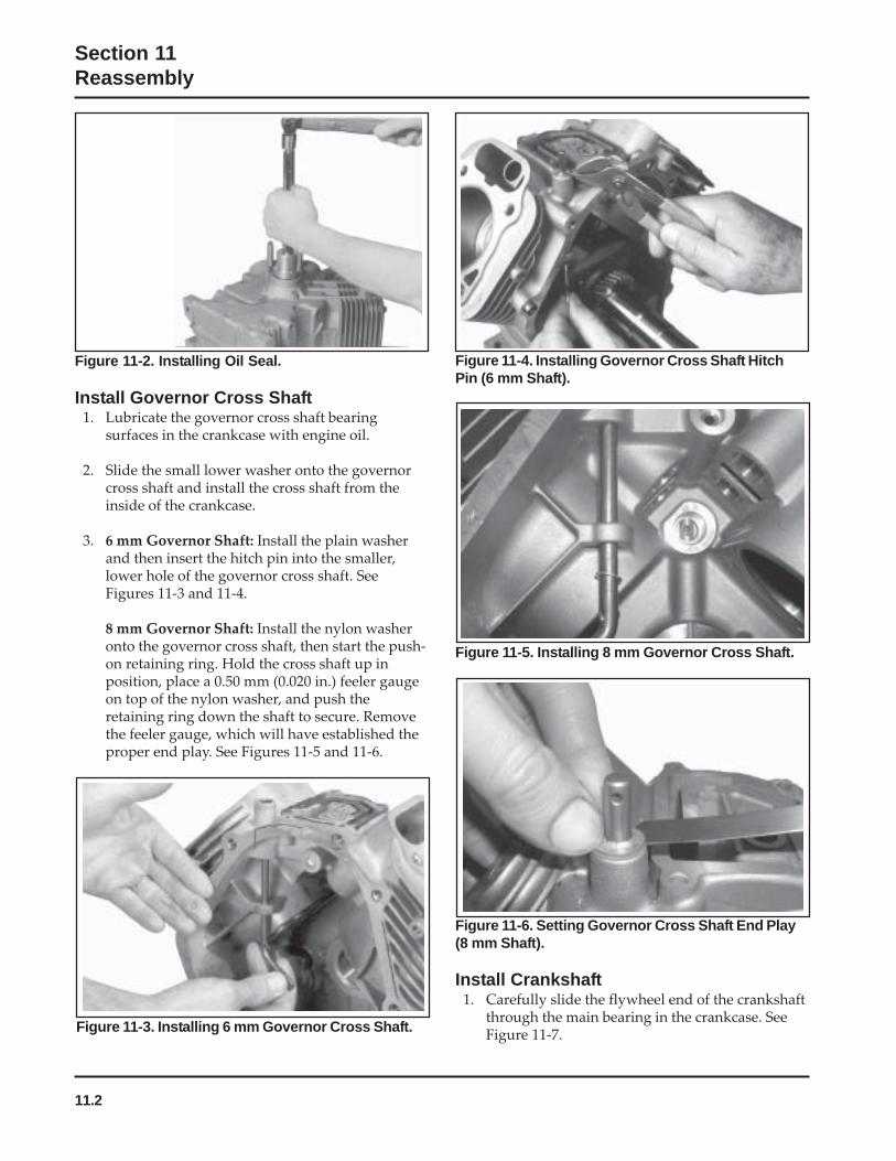
11.2
Section 11Reassembly
Figure 11-2. Installing Oil Seal.
Install Governor Cross Shaft1. Lubricate the governor cross shaft bearing
surfaces in the crankcase with engine oil.
2. Slide the small lower washer onto the governorcross shaft and install the cross shaft from theinside of the crankcase.
3. 6 mm Governor Shaft: Install the plain washerand then insert the hitch pin into the smaller,lower hole of the governor cross shaft. SeeFigures 11-3 and 11-4.
8 mm Governor Shaft: Install the nylon washeronto the governor cross shaft, then start the push-on retaining ring. Hold the cross shaft up inposition, place a 0.50 mm (0.020 in.) feeler gaugeon top of the nylon washer, and push theretaining ring down the shaft to secure. Removethe feeler gauge, which will have established theproper end play. See Figures 11-5 and 11-6.
Figure 11-4. Installing Governor Cross Shaft HitchPin (6 mm Shaft).
Figure 11-3. Installing 6 mm Governor Cross Shaft.
Figure 11-6. Setting Governor Cross Shaft End Play(8 mm Shaft).
Install Crankshaft1. Carefully slide the flywheel end of the crankshaft
through the main bearing in the crankcase. SeeFigure 11-7.
Figure 11-5. Installing 8 mm Governor Cross Shaft.

11.3
Section 11Reassembly
11
Figure 11-9. Installing Piston Assembly Using RingCompressor Tool.
5. Install the inner rod cap to the connecting rodusing the two hex flange screws. Three differenttypes of connecting rod bolts have been used andeach has a different torque value. If 8 mm straightshank type bolts are used, torque in increments to22.7 N·m (200 in. lb.). If 8 mm step-down boltsare used, torque in increments to 14.7 N·m(130 in. lb.). If 6 mm straight shank bolts areused, torque in increments to 11.3 N·m(100 in. lb.). Illustrated instructions are providedin the service rod package. See Figures 11-10 and11-11.
NOTE: Align the chamfer of the connecting rodwith the chamfer of its mating end cap.When installed, the flat faces of theconnecting rods should face each other.The faces with the raised rib should betoward the outside.
Figure 11-7. Installing Crankshaft.
Install Connecting Rods with Pistons andRingsNOTE: The cylinders are numbered on the crankcase.
Make sure to install the piston, connectingrod and end cap into its appropriate cylinderbore as previously marked at disassembly.Do not mix the end caps and connectingrods.
NOTE: Proper orientation of the piston/connectingrod assemblies inside the engine is extremelyimportant. Improper orientation can causeextensive wear or damage. Be certain thepistons and connecting rods are assembledexactly as shown in Figure 11-8.
1. Stagger the piston rings in the grooves until theend gaps are 120° apart. The oil ring rails shouldalso be staggered.
Figure 11-8. Piston, Connecting Rod, and End CapDetail.
Cylinder #1
Cylinder #2
2. Lubricate the cylinder bore, piston, and pistonrings with engine oil. Compress the rings of the#1 piston using a piston ring compressor.
3. Lubricate the crankshaft journals and connectingrod bearing surfaces with engine oil.
4. Make sure the “Fly” stamping on piston is facingtowards the flywheel side of the engine. Use ahammer with a rubber grip and gently tap thepiston into the cylinder as shown in Figure 11-9.Be careful that the oil ring rails do not spring freebetween the bottom of the ring compressor andtop of the cylinder.
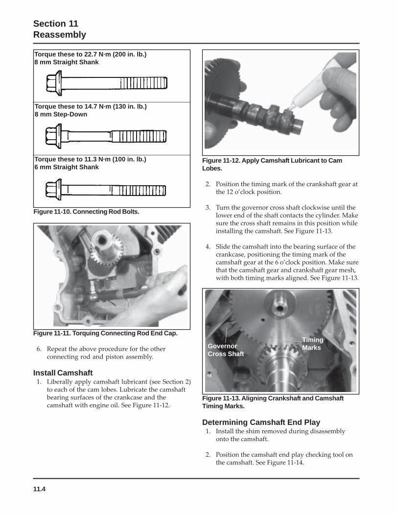
11.4
Section 11Reassembly
Figure 11-10. Connecting Rod Bolts.
Figure 11-12. Apply Camshaft Lubricant to CamLobes.
2. Position the timing mark of the crankshaft gear atthe 12 o’clock position.
3. Turn the governor cross shaft clockwise until thelower end of the shaft contacts the cylinder. Makesure the cross shaft remains in this position whileinstalling the camshaft. See Figure 11-13.
4. Slide the camshaft into the bearing surface of thecrankcase, positioning the timing mark of thecamshaft gear at the 6 o’clock position. Make surethat the camshaft gear and crankshaft gear mesh,with both timing marks aligned. See Figure 11-13.
Figure 11-11. Torquing Connecting Rod End Cap.
6. Repeat the above procedure for the otherconnecting rod and piston assembly.
Install Camshaft1. Liberally apply camshaft lubricant (see Section 2)
to each of the cam lobes. Lubricate the camshaftbearing surfaces of the crankcase and thecamshaft with engine oil. See Figure 11-12.
Figure 11-13. Aligning Crankshaft and CamshaftTiming Marks.
Determining Camshaft End Play1. Install the shim removed during disassembly
onto the camshaft.
2. Position the camshaft end play checking tool onthe camshaft. See Figure 11-14.
Torque these to 22.7 N·m (200 in. lb.)8 mm Straight Shank
Torque these to 14.7 N·m (130 in. lb.)8 mm Step-Down
Torque these to 11.3 N·m (100 in. lb.)6 mm Straight Shank
GovernorCross Shaft
TimingMarks
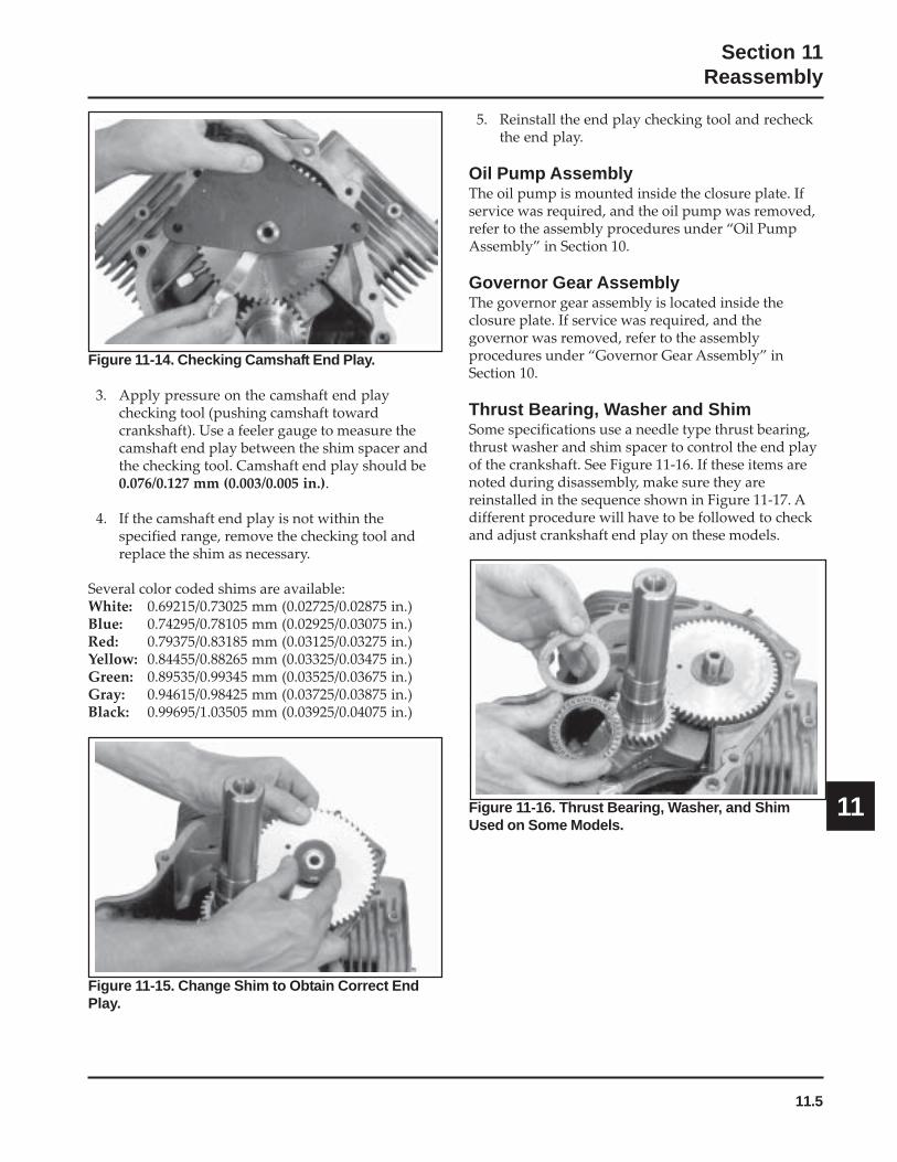
11.5
Section 11Reassembly
11
Figure 11-14. Checking Camshaft End Play.
3. Apply pressure on the camshaft end playchecking tool (pushing camshaft towardcrankshaft). Use a feeler gauge to measure thecamshaft end play between the shim spacer andthe checking tool. Camshaft end play should be0.076/0.127 mm (0.003/0.005 in.).
4. If the camshaft end play is not within thespecified range, remove the checking tool andreplace the shim as necessary.
Several color coded shims are available:White: 0.69215/0.73025 mm (0.02725/0.02875 in.)Blue: 0.74295/0.78105 mm (0.02925/0.03075 in.)Red: 0.79375/0.83185 mm (0.03125/0.03275 in.)Yellow: 0.84455/0.88265 mm (0.03325/0.03475 in.)Green: 0.89535/0.99345 mm (0.03525/0.03675 in.)Gray: 0.94615/0.98425 mm (0.03725/0.03875 in.)Black: 0.99695/1.03505 mm (0.03925/0.04075 in.)
5. Reinstall the end play checking tool and recheckthe end play.
Oil Pump AssemblyThe oil pump is mounted inside the closure plate. Ifservice was required, and the oil pump was removed,refer to the assembly procedures under “Oil PumpAssembly” in Section 10.
Governor Gear AssemblyThe governor gear assembly is located inside theclosure plate. If service was required, and thegovernor was removed, refer to the assemblyprocedures under “Governor Gear Assembly” inSection 10.
Thrust Bearing, Washer and ShimSome specifications use a needle type thrust bearing,thrust washer and shim spacer to control the end playof the crankshaft. See Figure 11-16. If these items arenoted during disassembly, make sure they arereinstalled in the sequence shown in Figure 11-17. Adifferent procedure will have to be followed to checkand adjust crankshaft end play on these models.
Figure 11-15. Change Shim to Obtain Correct EndPlay.
Figure 11-16. Thrust Bearing, Washer, and ShimUsed on Some Models.

11.6
Section 11Reassembly
Remove the closure plate. If end play requiresadjustment, remove the original spacer and install theappropriate size shim spacer in its place. Then followthe procedure under “Install Closure Plate Assembly.”
Install Closure Plate Oil Seal1. Check to make sure that there are no nicks or
burrs in the crankshaft bore of the closure plate.
2. Apply a light coat of engine oil to the outsidediameter of the oil seal.
3. Drive the oil seal into the closure plate using aseal driver. Make sure the oil seal is installedstraight and true in the bore to the depth shownin Figure 11-18.
Figure 11-17. Correct Sequence of Thrust Bearing,Washer, and Shim in Closure Plate.
The race for the thrust bearing presses loosely into theclosure plate. If it is not already installed, push it intothe crankshaft bore inside the closure plate. Pack thethrust bearing with heavy grease and stick the bearinginto the race. Wipe some grease on the face of thethrust washer and stick it onto the thrust bearing.Wipe some grease on the face of the original shimspacer and stick it onto the thrust washer.
Install the closure plate onto the crankcase withoutapplying RTV sealant and secure it with only two orthree of the fasteners at this time. Use a dial indicatorto check the crankshaft end play. End play should be0.05/0.50 mm (0.0020/0.0197 in.), except for CH25engines below Serial No. 2403500008 end play shouldbe 0.050/0.75 mm (0.0020/0.0295 in.). Shim spacers areavailable in the three color coded thicknesses listedbelow if adjustment is needed.
Crankshaft End Play ShimsGREEN 0.8366-0.9127 mm
(0.8750 mm/0.034 in. Nominal)
YELLOW 1.0652-1.1414 mm(1.1033 mm/0.043 in. Nominal)
RED 1.2938-1.3700 mm(1.3319 mm/0.052 in. Nominal)
ClosurePlate
BearingRace
Thrust Shim
Needle ThrustBearing
ThrustWasher
Oil Seal
8.0 mm(0.314 in.)
Seal Depth
Figure 11-18. Oil Seal Depth in Closure Plate.
Install Closure Plate AssemblyRTV sealant is used as a gasket between the closureplate and the crankcase. Refer to Section 2 for a listingof approved sealants. Always use fresh sealant. Usingoutdated sealant can result in leakage.
1. Be sure the sealing surfaces have been cleanedand prepared as described at the beginning ofSection 10 or in Service Bulletin 252.
2. Check to make sure that there are no nicks orburrs on the sealing surfaces of the closure plateor crankcase.

11.7
Section 11Reassembly
11
Figure 11-19. Closure Plate Sealant Pattern.
4. Make sure the end of the governor cross shaft islying against the bottom of cylinder 1 inside thecrankcase. See Figure 11-13.
5. Install the closure plate to the crankcase.Carefully seat the camshaft and the crankshaftinto their mating bearings. Rotate the crankshaftslightly to help engage the oil pump andgovernor gear meshes. See Figure 11-20.
Figure 11-22. Torquing Closure Plate Fasteners.
Install Stator and Backing Plates1. Apply pipe sealant with Teflon® (Loctite® No
59241 or equivalent) to the stator mounting holes.
2. Position the stator aligning the mounting holes sothat the leads are at the bottom, towards thecrankcase.
3. Install and torque the two hex flange screws to6.2 N·m (55 in. lb.). See Figure 11-23.
3. Apply a 1.5 mm (1/16 in.) bead of sealant to thesealing surface of the closure plate. See Figure11-19 for sealant pattern.
Figure 11-20. Using Spanner Wrench to TurnCrankshaft.
1
10
8
6
42
9
7
5
3
6. Install the ten hex flange screws securing theclosure plate to the crankcase. Torque fasteners inthe sequence shown in Figure 11-21 to 24.4 N·m(216 in. lb.). On some engines one of the tenmounting screws is plated. The plated screw istypically installed in the #6 hole shown in Figure11-21.
Figure 11-21. Closure Plate Fastener TorqueSequence.

11.8
Section 11Reassembly
Install Flywheel
WARNING: Damaging Crankshaft andFlywheel Can Cause Personal Injury!
Using improper procedures to install the flywheel can crackor damage the crankshaft and/or flywheel. This not onlycauses extensive engine damage, but can also cause personalinjury, since broken fragments could be thrown from theengine. Always observe and use the following precautionsand procedures when installing the flywheel.
NOTE: Before installing the flywheel make sure thecrankshaft taper and the flywheel hub areclean, dry, and completely free of anylubricants. The presence of lubricants cancause the flywheel to be over stressed anddamaged when the hex flange screw istorqued to specifications.
Figure 11-23. Torquing Stator Screws.
4. Route the stator leads in the crankcase channel,then install the backing plates and the stator wirebracket (if used). Secure using the four hex flangescrews. See Figures 11-24 and 11-25. Torque thescrews to 7.3 N·m (65 in. lb.).
Figure 11-24. Route Stator Leads in Groove.
Figure 11-26. Clean and Dry Taper of Crankshaft.
Figure 11-25. Installing Backing Plates and StatorWire Bracket.
Figure 11-27. Clean and Dry Flywheel Hub.
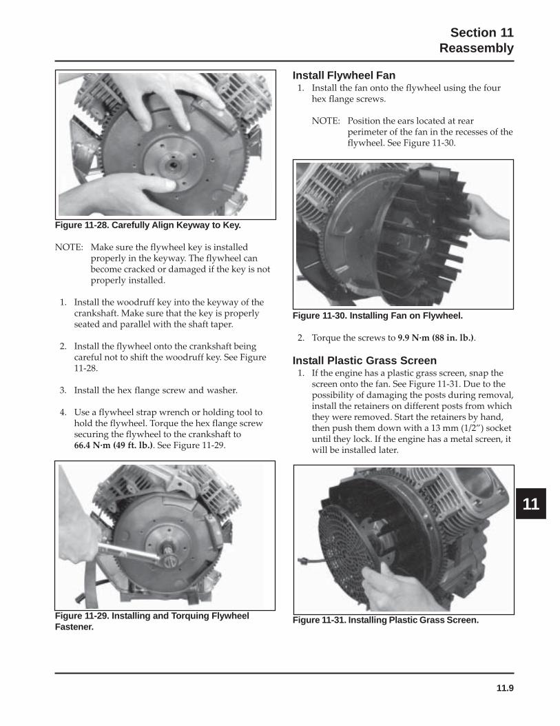
11.9
Section 11Reassembly
11
Figure 11-29. Installing and Torquing FlywheelFastener.
Install Flywheel Fan1. Install the fan onto the flywheel using the four
hex flange screws.
NOTE: Position the ears located at rearperimeter of the fan in the recesses of theflywheel. See Figure 11-30.
Figure 11-28. Carefully Align Keyway to Key.
NOTE: Make sure the flywheel key is installedproperly in the keyway. The flywheel canbecome cracked or damaged if the key is notproperly installed.
1. Install the woodruff key into the keyway of thecrankshaft. Make sure that the key is properlyseated and parallel with the shaft taper.
2. Install the flywheel onto the crankshaft beingcareful not to shift the woodruff key. See Figure11-28.
3. Install the hex flange screw and washer.
4. Use a flywheel strap wrench or holding tool tohold the flywheel. Torque the hex flange screwsecuring the flywheel to the crankshaft to66.4 N·m (49 ft. lb.). See Figure 11-29.
Figure 11-30. Installing Fan on Flywheel.
2. Torque the screws to 9.9 N·m (88 in. lb.).
Install Plastic Grass Screen1. If the engine has a plastic grass screen, snap the
screen onto the fan. See Figure 11-31. Due to thepossibility of damaging the posts during removal,install the retainers on different posts from whichthey were removed. Start the retainers by hand,then push them down with a 13 mm (1/2”) socketuntil they lock. If the engine has a metal screen, itwill be installed later.
Figure 11-31. Installing Plastic Grass Screen.
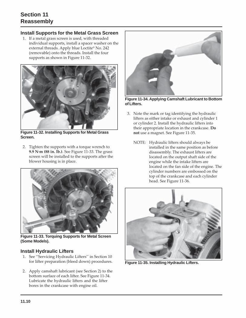
11.10
Section 11Reassembly
Install Supports for the Metal Grass Screen1. If a metal grass screen is used, with threaded
individual supports, install a spacer washer on theexternal threads. Apply blue Loctite® No. 242(removable) onto the threads. Install the foursupports as shown in Figure 11-32.
Figure 11-32. Installing Supports for Metal GrassScreen.
2. Tighten the supports with a torque wrench to9.9 N·m (88 in. lb.). See Figure 11-33. The grassscreen will be installed to the supports after theblower housing is in place.
Figure 11-33. Torquing Supports for Metal Screen(Some Models).
Install Hydraulic Lifters1. See ‘‘Servicing Hydraulic Lifters’’ in Section 10
for lifter preparation (bleed down) procedures.
2. Apply camshaft lubricant (see Section 2) to thebottom surface of each lifter. See Figure 11-34.Lubricate the hydraulic lifters and the lifterbores in the crankcase with engine oil.
Figure 11-34. Applying Camshaft Lubricant to Bottomof Lifters.
3. Note the mark or tag identifying the hydrauliclifters as either intake or exhaust and cylinder 1or cylinder 2. Install the hydraulic lifters intotheir appropriate location in the crankcase. Donot use a magnet. See Figure 11-35.
NOTE: Hydraulic lifters should always beinstalled in the same position as beforedisassembly. The exhaust lifters arelocated on the output shaft side of theengine while the intake lifters arelocated on the fan side of the engine. Thecylinder numbers are embossed on thetop of the crankcase and each cylinderhead. See Figure 11-36.
Figure 11-35. Installing Hydraulic Lifters.

11.11
Section 11Reassembly
11
Figure 11-36. Match Numbers on Cylinder Barrel andHead. Figure 11-38. Valve Components.
IntakeValveSeal
Valve
Keepers
Retainer
Spring Cap
Figure 11-39. Installing Valves with Valve SpringCompressor.
Install Cylinder HeadsNOTE: Cylinder heads must be attached with the
original type of mounting hardware, usingeither hex flange screws, or mounting studswith nuts and washers. The heads aremachined differently for studs than forscrews, so the fastening method cannot bealtered unless the heads are being replaced.Do not intermix the components.
1. Check to make sure there are no nicks or burrs onthe sealing surfaces of the cylinder head or thecrankcase.
Figure 11-37. Intake Valve Seal Location.
Valve Stem SealsThese engines use valve stem seals on the intakevalves and occasionally on the exhaust valves. Alwaysuse a new seal whenever the valve is removed or if theseal is deteriorated or damaged in any way. Neverreuse an old seal. Figure 11-37.
Assemble Cylinder HeadsPrior to installation, lubricate all components withengine oil, paying particular attention to the lip of thevalve stem seal, valve stems and valve guides. Installthe following items in the order listed below using avalve spring compressor. See Figures 11-38 and 11-39.
• Intake and exhaust valves• Valve spring caps• Valve springs• Valve spring retainers• Valve spring keepers
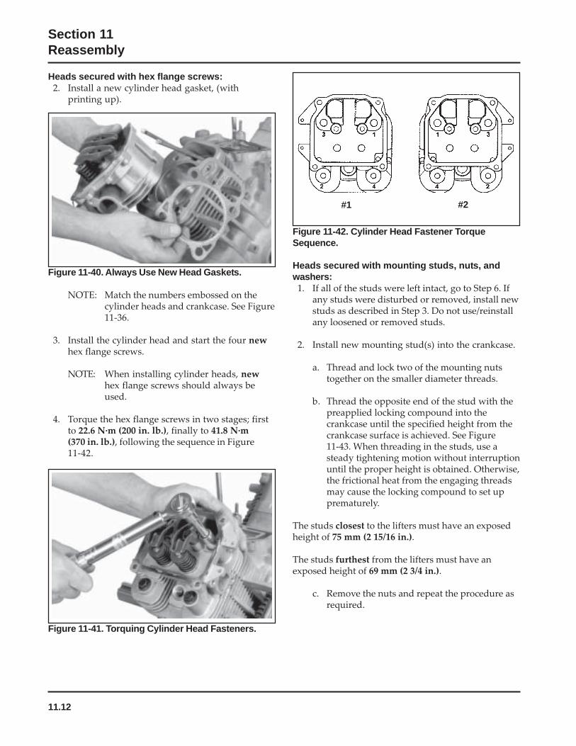
11.12
Section 11Reassembly
Figure 11-41. Torquing Cylinder Head Fasteners.
Figure 11-42. Cylinder Head Fastener TorqueSequence.
Heads secured with mounting studs, nuts, andwashers:
1. If all of the studs were left intact, go to Step 6. Ifany studs were disturbed or removed, install newstuds as described in Step 3. Do not use/reinstallany loosened or removed studs.
2. Install new mounting stud(s) into the crankcase.
a. Thread and lock two of the mounting nutstogether on the smaller diameter threads.
b. Thread the opposite end of the stud with thepreapplied locking compound into thecrankcase until the specified height from thecrankcase surface is achieved. See Figure11-43. When threading in the studs, use asteady tightening motion without interruptionuntil the proper height is obtained. Otherwise,the frictional heat from the engaging threadsmay cause the locking compound to set upprematurely.
The studs closest to the lifters must have an exposedheight of 75 mm (2 15/16 in.).
The studs furthest from the lifters must have anexposed height of 69 mm (2 3/4 in.).
c. Remove the nuts and repeat the procedure asrequired.
Figure 11-40. Always Use New Head Gaskets.
NOTE: Match the numbers embossed on thecylinder heads and crankcase. See Figure11-36.
3. Install the cylinder head and start the four newhex flange screws.
NOTE: When installing cylinder heads, newhex flange screws should always beused.
4. Torque the hex flange screws in two stages; firstto 22.6 N·m (200 in. lb.), finally to 41.8 N·m(370 in. lb.), following the sequence in Figure11-42.
Heads secured with hex flange screws:2. Install a new cylinder head gasket, (with
printing up).
#1 #2
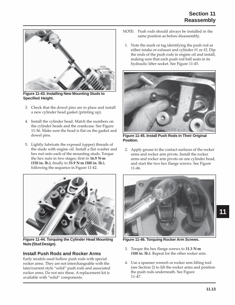
11.13
Section 11Reassembly
11
Figure 11-43. Installing New Mounting Studs toSpecified Height.
3. Check that the dowel pins are in place and installa new cylinder head gasket (printing up).
4. Install the cylinder head. Match the numbers onthe cylinder heads and the crankcase. See Figure11-36. Make sure the head is flat on the gasket anddowel pins.
5. Lightly lubricate the exposed (upper) threads ofthe studs with engine oil. Install a flat washer andhex nut onto each of the mounting studs. Torquethe hex nuts in two stages; first to 16.9 N·m(150 in. lb.), finally to 33.9 N·m (300 in. lb.),following the sequence in Figure 11-42.
Figure 11-46. Torquing Rocker Arm Screws.
3. Torque the hex flange screws to 11.3 N·m(100 in. lb.). Repeat for the other rocker arm.
4. Use a spanner wrench or rocker arm lifting tool(see Section 2) to lift the rocker arms and positionthe push rods underneath. See Figure11-47.
NOTE: Push rods should always be installed in thesame position as before disassembly.
1. Note the mark or tag identifying the push rod aseither intake or exhaust and cylinder #1 or #2. Dipthe ends of the push rods in engine oil and install,making sure that each push rod ball seats in itshydraulic lifter socket. See Figure 11-45.
Figure 11-44. Torquing the Cylinder Head MountingNuts (Stud Design).
Install Push Rods and Rocker ArmsEarly models used hollow push rods with specialrocker arms. They are not interchangeable with thelater/current style “solid” push rods and associatedrocker arms. Do not mix these. A replacement kit isavailable with “solid” components.
Figure 11-45. Install Push Rods in Their OriginalPosition.
2. Apply grease to the contact surfaces of the rockerarms and rocker arm pivots. Install the rockerarms and rocker arm pivots on one cylinder head,and start the two hex flange screws. See Figure11-46.
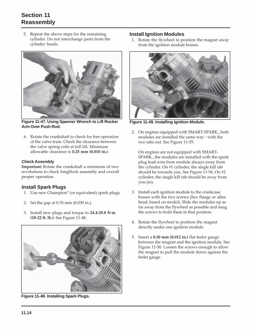
11.14
Section 11Reassembly
5. Repeat the above steps for the remainingcylinder. Do not interchange parts from thecylinder heads.
Figure 11-47. Using Spanner Wrench to Lift RockerArm Over Push Rod.
6. Rotate the crankshaft to check for free operationof the valve train. Check the clearance betweenthe valve spring coils at full lift. Minimumallowable clearance is 0.25 mm (0.010 in.).
Check AssemblyImportant: Rotate the crankshaft a minimum of tworevolutions to check longblock assembly and overallproper operation.
Install Spark Plugs1. Use new Champion® (or equivalent) spark plugs.
2. Set the gap at 0.76 mm (0.030 in.).
3. Install new plugs and torque to 24.4-29.8 N·m(18-22 ft. lb.). See Figure 11-48.
Figure 11-48. Installing Spark Plugs.
Figure 11-49. Installing Ignition Module.
2. On engines equipped with SMART-SPARK™
bothmodules are installed the same way - with thetwo tabs out. See Figure 11-55.
On engines are not equipped with SMART-SPARK
™the modules are installed with the spark
plug lead wire from module always away fromthe cylinder. On #1 cylinder, the single kill tabshould be towards you. See Figure 11-54. On #2cylinder, the single kill tab should be away fromyou (in).
3. Install each ignition module to the crankcasebosses with the two screws (hex flange or allenhead, based on model). Slide the modules up asfar away from the flywheel as possible and snugthe screws to hold them in that position.
4. Rotate the flywheel to position the magnetdirectly under one ignition module.
5. Insert a 0.30 mm (0.012 in.) flat feeler gaugebetween the magnet and the ignition module. SeeFigure 11-50. Loosen the screws enough to allowthe magnet to pull the module down against thefeeler gauge.
Install Ignition Modules1. Rotate the flywheel to position the magnet away
from the ignition module bosses.

11.15
Section 11Reassembly
11
Figure 11-50. Setting Ignition Module Air Gap.
6. Torque the screws to 4.0-6.2 N·m (35-55 in. lb.).
7. Repeat steps 4 through 6 for the other ignitionmodule.
8. Rotate the flywheel back and forth checking forclearance between the magnet and ignitionmodules. Make sure the magnet does not strikethe modules. Check the gap with a feeler gaugeand readjust if necessary. Final air gap:0.280/0.330 mm (0.011/0.013 in.).
Install Intake Manifold1. Install the intake manifold and new gaskets or
O-Rings (plastic manifold), with wiring harnessattached, to the cylinder heads. Slide any wiringharness clips onto the appropriate bolts beforeinstalling. Make sure the gaskets are in theproper orientation. Torque the four screws intwo stages, first to 7.4 N·m (66 in. lb.), then to9.9 N·m (88 in. lb.), using the sequence shown inFigure 11-51.
1 2
3 4
Sealant
Figure 11-51. Intake Manifold Torque Sequence.
Figure 11-52. Sealant Applied to Terminals.
NOTE: If the wires were disconnected from theignition modules on engines with SMART-SPARK
™, reattach the leads and seal the base
of the terminal connectors with GE/Novaguard G661 (see Section 2) or Fel-ProLubri-Sel dielectric compound. The beadsshould overlap between the terminals* toform a solid bridge of compound. See Figure11-52. Do not put any compound inside theterminals.
*The 24 584 15-S ignition modules have aseparator barrier between the terminals. On thesemodules, seal the base of the terminals, but it isnot necessary to have overlapping beads ofsealant between the connections.
2. Two-Barrel Manifold (Carburetor) Models:Route the wiring harness through the mountingclip on the underside of debris shield if separatedearlier. Carefully position the debris shield to therear as far as possible. See Figure 11-53.
Figure 11-53. Routing of Wiring Harness (Two-BarrelModels).

11.16
Section 11Reassembly
Figure 11-56. Installing Breather Reed Assembly.
4. Insert the breather filter into position in thecrankcase. Make sure no filter strands are on thesealing surface. See Figure 11-57.
5. Install the new breather gasket.
Figure 11-54. Connecting Kill Leads on StandardIgnition Modules.
Figure 11-55. Connect Leads on SMART-SPARK™
Ignition Modules.
Install Breather Cover and Inner BafflesRTV sealant was used on early models between thebreather cover and the crankcase. A gasket withimprinted sealant beads is now used andrecommended. Install as follows:
1. Be sure the sealing surfaces of the crankcase andbreather cover are clean of old gasket material orRTV sealant. Do not scrape the surfaces as thiscould result in leakage.
2. Check to make sure there are no nicks or burrs onsealing surfaces.
Figure 11-57. Installing New Breather Filter.
6. Carefully position the breather cover on thecrankcase. Install first two hex flange screws atpositions shown in Figure 11-58 and fingertighten at this time.
3. Connect the kill lead to the tab terminal onstandard ignition modules. See Figure 11-54.
3. Install the breather reed and breather reedretainer onto the crankcase and secure with thehex flange screw. Hold the assembly in line whentightening. Torque the screw to 3.9 N·m(35 in. lb.). See Figure 11-56.
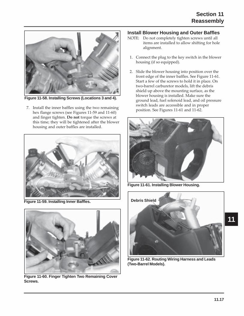
11.17
Section 11Reassembly
11
Figure 11-58. Installing Screws (Locations 3 and 4).
7. Install the inner baffles using the two remaininghex flange screws (see Figures 11-59 and 11-60)and finger tighten. Do not torque the screws atthis time; they will be tightened after the blowerhousing and outer baffles are installed.
Figure 11-59. Installing Inner Baffles.
Figure 11-60. Finger Tighten Two Remaining CoverScrews.
Install Blower Housing and Outer BafflesNOTE: Do not completely tighten screws until all
items are installed to allow shifting for holealignment.
1. Connect the plug to the key switch in the blowerhousing (if so equipped).
2. Slide the blower housing into position over thefront edge of the inner baffles. See Figure 11-61.Start a few of the screws to hold it in place. Ontwo-barrel carburetor models, lift the debrisshield up above the mounting surface, as theblower housing is installed. Make sure theground lead, fuel solenoid lead, and oil pressureswitch leads are accessible and in properposition. See Figures 11-61 and 11-62.
Figure 11-61. Installing Blower Housing.
Figure 11-62. Routing Wiring Harness and Leads(Two-Barrel Models).
Debris Shield
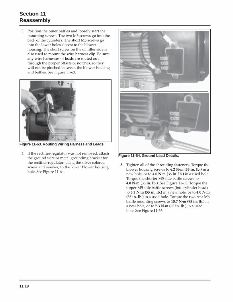
11.18
Section 11Reassembly
Figure 11-64. Ground Lead Details.
5. Tighten all of the shrouding fasteners. Torque theblower housing screws to 6.2 N·m (55 in. lb.) in anew hole, or to 4.0 N·m (35 in. lb.) in a used hole.Torque the shorter M5 side baffle screws to4.0 N·m (35 in. lb.). See Figure 11-65. Torque theupper M5 side baffle screws (into cylinder head)to 6.2 N·m (55 in. lb.) in a new hole, or to 4.0 N·m(35 in. lb.) in a used hole. Torque the two rear M6baffle mounting screws to 10.7 N·m (95 in. lb.) ina new hole, or to 7.3 N·m (65 in. lb.) in a usedhole. See Figure 11-66.
3. Position the outer baffles and loosely start themounting screws. The two M6 screws go into theback of the cylinders. The short M5 screws gointo the lower holes closest to the blowerhousing. The short screw on the oil filter side isalso used to mount the wire harness clip. Be sureany wire harnesses or leads are routed outthrough the proper offsets or notches, so theywill not be pinched between the blower housingand baffles. See Figure 11-63.
Figure 11-63. Routing Wiring Harness and Leads.
4. If the rectifier-regulator was not removed, attachthe ground wire or metal grounding bracket forthe rectifier-regulator, using the silver coloredscrew and washer, to the lower blower housinghole. See Figure 11-64.
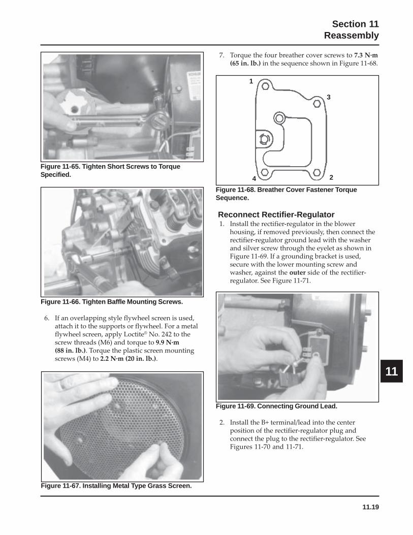
11.19
Section 11Reassembly
11
Figure 11-66. Tighten Baffle Mounting Screws.
6. If an overlapping style flywheel screen is used,attach it to the supports or flywheel. For a metalflywheel screen, apply Loctite® No. 242 to thescrew threads (M6) and torque to 9.9 N·m(88 in. lb.). Torque the plastic screen mountingscrews (M4) to 2.2 N·m (20 in. lb.).
Figure 11-65. Tighten Short Screws to TorqueSpecified.
Figure 11-68. Breather Cover Fastener TorqueSequence.
Reconnect Rectifier-Regulator1. Install the rectifier-regulator in the blower
housing, if removed previously, then connect therectifier-regulator ground lead with the washerand silver screw through the eyelet as shown inFigure 11-69. If a grounding bracket is used,secure with the lower mounting screw andwasher, against the outer side of the rectifier-regulator. See Figure 11-71.
1
2
3
4
Figure 11-67. Installing Metal Type Grass Screen.
7. Torque the four breather cover screws to 7.3 N·m(65 in. lb.) in the sequence shown in Figure 11-68.
Figure 11-69. Connecting Ground Lead.
2. Install the B+ terminal/lead into the centerposition of the rectifier-regulator plug andconnect the plug to the rectifier-regulator. SeeFigures 11-70 and 11-71.

11.20
Section 11Reassembly
Figure 11-72. Reinstalling SAM Module.
Install Electric Starter Motor1. Install the starter motor using the two hex flange
screws. See Figure 11-73. Some inertia-drivestarters have a pinion cover and spacers on thestarter bolts.
2. Torque the two hex flange screws to 15.3 N·m(135 in. lb.).
Figure 11-73. Installing Electric Starter Motor.
Cylinder Baffle Mounting Location
Blower Housing Mounting Location
Figure 11-71. Grounding Bracket and AttachedConnector.
SMART-SPARK™ Module1. On engines with SMART-SPARK
™, reinstall the
SAM module to the blower housing or cylinderbaffle. Do not overtighten the retaining screws.See Figure 11-72.
Figure 11-70. Installing B+ Lead into Plug.
GroundingBracket
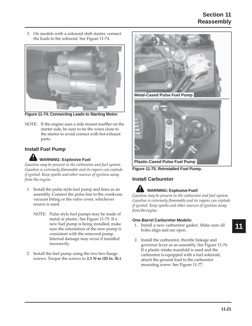
11.21
Section 11Reassembly
11
Figure 11-74. Connecting Leads to Starting Motor.
NOTE: If the engine uses a side mount muffler on thestarter side, be sure to tie the wires close tothe starter to avoid contact with hot exhaustparts.
Install Fuel Pump
WARNING: Explosive FuelGasoline may be present in the carburetor and fuel system.Gasoline is extremely flammable and its vapors can explodeif ignited. Keep sparks and other sources of ignition awayfrom the engine.
1. Install the pulse style fuel pump and lines as anassembly. Connect the pulse line to the crankcasevacuum fitting or the valve cover, whicheversource is used.
NOTE: Pulse style fuel pumps may be made ofmetal or plastic. See Figure 11-75. If anew fuel pump is being installed, makesure the orientation of the new pump isconsistent with the removed pump.Internal damage may occur if installedincorrectly.
2. Install the fuel pump using the two hex flangescrews. Torque the screws to 2.3 N·m (20 in. lb.).
3. On models with a solenoid shift starter, connectthe leads to the solenoid. See Figure 11-74.
Figure 11-75. Reinstalled Fuel Pump.
Install Carburetor
WARNING: Explosive Fuel!Gasoline may be present in the carburetor and fuel system.Gasoline is extremely flammable and its vapors can explodeif ignited. Keep sparks and other sources of ignition awayfrom the engine.
One-Barrel Carburetor Models:1. Install a new carburetor gasket. Make sure all
holes align and are open.
2. Install the carburetor, throttle linkage andgovernor lever as an assembly. See Figure 11-76.If a plastic intake manifold is used and thecarburetor is equipped with a fuel solenoid,attach the ground lead to the carburetormounting screw. See Figure 11-77.
Metal-Cased Pulse Fuel Pump
Plastic-Cased Pulse Fuel Pump
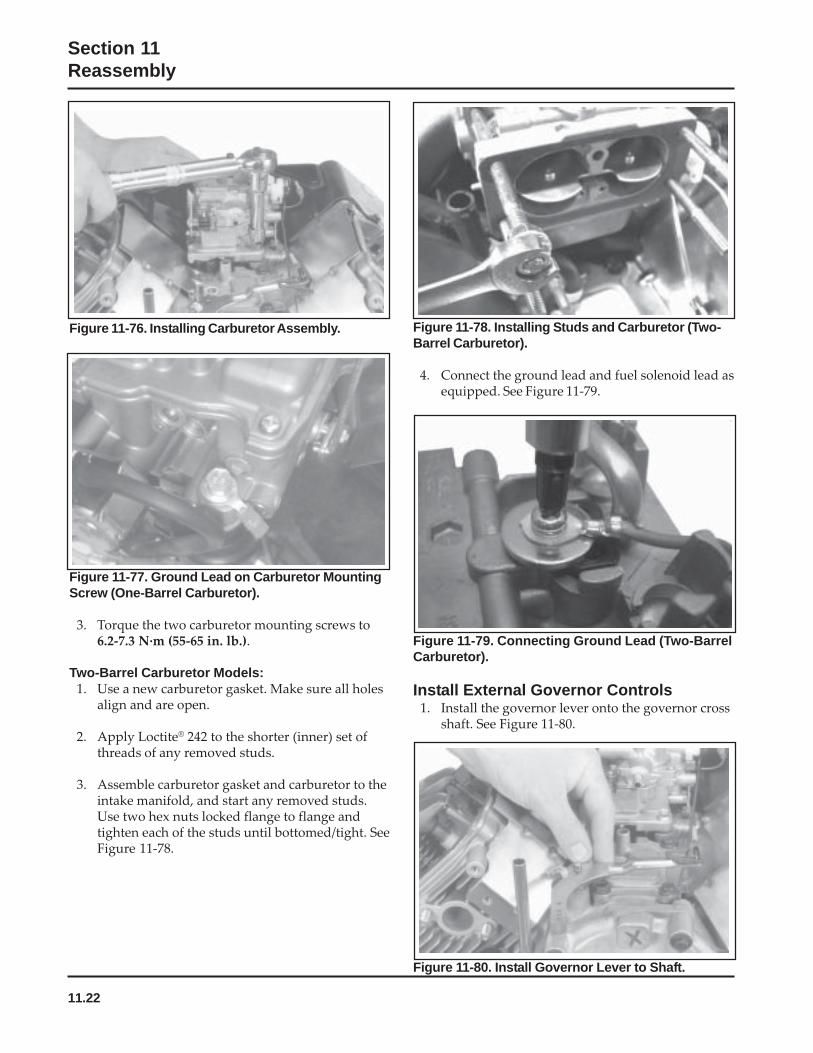
11.22
Section 11Reassembly
Figure 11-77. Ground Lead on Carburetor MountingScrew (One-Barrel Carburetor).
3. Torque the two carburetor mounting screws to6.2-7.3 N·m (55-65 in. lb.).
Two-Barrel Carburetor Models:1. Use a new carburetor gasket. Make sure all holes
align and are open.
2. Apply Loctite® 242 to the shorter (inner) set ofthreads of any removed studs.
3. Assemble carburetor gasket and carburetor to theintake manifold, and start any removed studs.Use two hex nuts locked flange to flange andtighten each of the studs until bottomed/tight. SeeFigure 11-78.
Figure 11-76. Installing Carburetor Assembly.
Figure 11-79. Connecting Ground Lead (Two-BarrelCarburetor).
Install External Governor Controls1. Install the governor lever onto the governor cross
shaft. See Figure 11-80.
Figure 11-78. Installing Studs and Carburetor (Two-Barrel Carburetor).
4. Connect the ground lead and fuel solenoid lead asequipped. See Figure 11-79.
Figure 11-80. Install Governor Lever to Shaft.
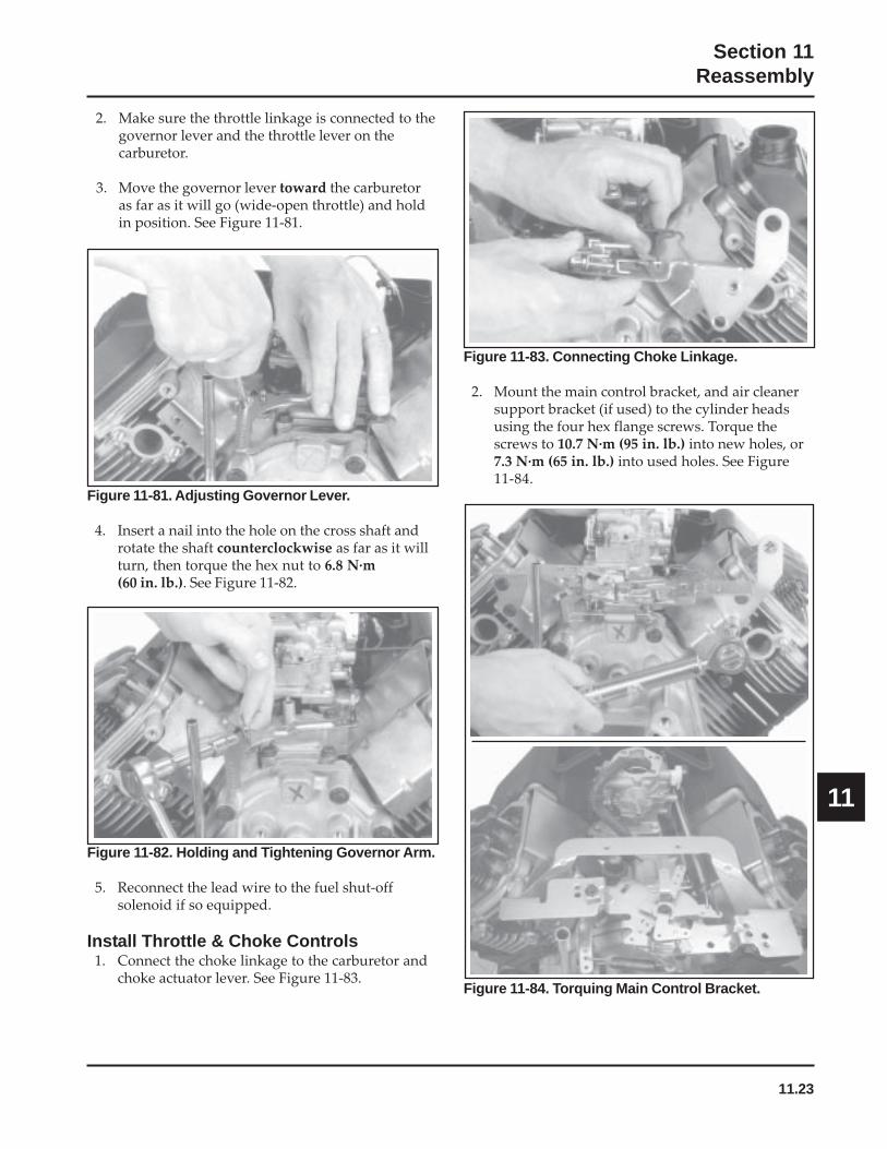
11.23
Section 11Reassembly
11
Figure 11-81. Adjusting Governor Lever.
4. Insert a nail into the hole on the cross shaft androtate the shaft counterclockwise as far as it willturn, then torque the hex nut to 6.8 N·m(60 in. lb.). See Figure 11-82.
Figure 11-82. Holding and Tightening Governor Arm.
5. Reconnect the lead wire to the fuel shut-offsolenoid if so equipped.
Install Throttle & Choke Controls1. Connect the choke linkage to the carburetor and
choke actuator lever. See Figure 11-83.
Figure 11-83. Connecting Choke Linkage.
2. Mount the main control bracket, and air cleanersupport bracket (if used) to the cylinder headsusing the four hex flange screws. Torque thescrews to 10.7 N·m (95 in. lb.) into new holes, or7.3 N·m (65 in. lb.) into used holes. See Figure11-84.
Figure 11-84. Torquing Main Control Bracket.
2. Make sure the throttle linkage is connected to thegovernor lever and the throttle lever on thecarburetor.
3. Move the governor lever toward the carburetoras far as it will go (wide-open throttle) and holdin position. See Figure 11-81.

11.24
Section 11Reassembly
Figure 11-85. Connecting Spring to Governor Lever.
3. Connect the governor spring from the maincontrol bracket to the appropriate hole in thegovernor lever as indicated in the followingcharts. Note that hole positions are counted fromthe pivot point of the governor lever. See Figures11-85 and 11-86, and the appropriate chart.
6 mm Governor Lever and Hole Position/RPM Chart
3801-40003601-38003451-36003301-34503101-33002951-31002800-29503750*3150*
High Idle RPMGov. LeverHole No.
Governor SpringColor Code
543243233
ClearClearClearClear
PurplePurplePurpleClear
Purple
*5% Regulation (others 10%)
654321GovernedIdle Hole
GovernorLever
Figure 11-86. Governor Spring I.D. Color Markings.
Colored on End Only
Colored Completely
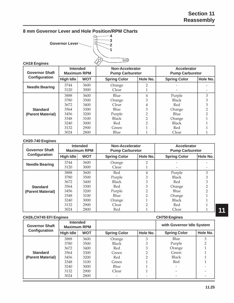
11.25
Section 11Reassembly
11CH26,CH745 EFI Engines
Governor ShaftConfiguration
High Idle WOT
IntendedMaximum RPM
Spring Color Hole No.
CH20-740 EnginesAccelerator
Pump Carburetor
Spring Color Hole No.
--
--
PurpleBlackRed
OrangeBlue
OrangeBlackRed
Clear
333221111
Governor ShaftConfiguration
Needle Bearing
Standard(Parent Material)
Non-AcceleratorPump Carburetor
High Idle WOT
IntendedMaximum RPM
37443120
36003000
Spring Color Hole No.
388837803672356434563348324031323024
360035003400330032003100300029002800
OrangeClear
21
RedPurpleBlackRed
PurpleBlue
OrangeClearRed
433322121
Standard(Parent Material)
388837803672356434563348324031323024
360035003400330032003100300029002800
OrangeBlackRed
GreenRed
GreenBlueClear
-
33322111-
8 mm Governor Lever and Hole Position/RPM Charts
Governor ShaftConfiguration
Needle Bearing
Standard(Parent Material)
Non-AcceleratorPump Carburetor
AcceleratorPump Carburetor
High Idle WOT
IntendedMaximum RPM
37443120
36003000
Spring Color Hole No. Spring Color Hole No.
388837803672356434563348324031323024
360035003400330032003100300029002800
OrangeClear
21
--
--
BlueOrangeClearBlue
PurpleBlackRed
GreenBlue
434322211
PurpleBlackRed
OrangeBlue
OrangeBlackRed
Clear
333221111
CH18 Engines
4321
Governor Lever
Spring Color Hole No.
BluePurpleOrangeGreenBlackRed
---
321111---
CH750 Engines
with Governor Idle System

11.26
Section 11Reassembly
Figure 11-87. Throttle/Choke Control Bracket Detail.
Install Oil Sentry™ (If So Equipped)1. Apply pipe sealant with Teflon® (Loctite® No.
59241 or equivalent) to the threads of the OilSentry™ switch and install it into the breathercover. See Figure 11-88. Torque to 4.5 N·m(40 in. lb.).
2. Connect the wire lead (green) to the Oil Sentry™
terminal.
Install Control Panel (If So Equipped)1. Install the panel to the blower housing.
2. Connect the throttle control cable or shaft.
3. Connect the choke control cable to the controlbracket.
4. Connect the Oil Sentry™ indicator light wires.
Figure 11-88. Installing Oil Sentry™ Switch.
Item Description1 Bracket, speed control2 Clamp, cable (some applications)3 Kill Switch (some applications)4 Lever, choke (top position)5 Lever, throttle control (middle)6 Linkage, choke control7 Lever, throttle actuator (bottom)8 Screw, M5x0.8x209 Washer, wave
10 Washer, flat (3)11 Spring, choke return12 Nut, M5x0.8 lock
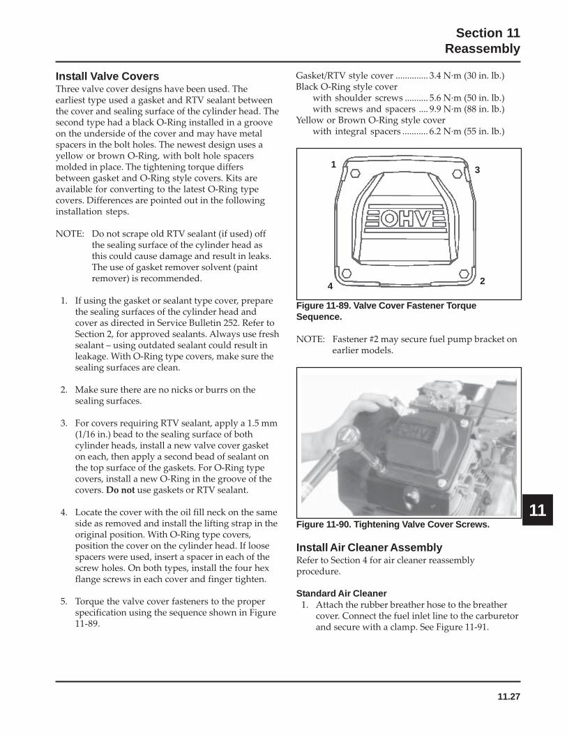
11.27
Section 11Reassembly
11
Install Valve CoversThree valve cover designs have been used. Theearliest type used a gasket and RTV sealant betweenthe cover and sealing surface of the cylinder head. Thesecond type had a black O-Ring installed in a grooveon the underside of the cover and may have metalspacers in the bolt holes. The newest design uses ayellow or brown O-Ring, with bolt hole spacersmolded in place. The tightening torque differsbetween gasket and O-Ring style covers. Kits areavailable for converting to the latest O-Ring typecovers. Differences are pointed out in the followinginstallation steps.
NOTE: Do not scrape old RTV sealant (if used) offthe sealing surface of the cylinder head asthis could cause damage and result in leaks.The use of gasket remover solvent (paintremover) is recommended.
1. If using the gasket or sealant type cover, preparethe sealing surfaces of the cylinder head andcover as directed in Service Bulletin 252. Refer toSection 2, for approved sealants. Always use freshsealant – using outdated sealant could result inleakage. With O-Ring type covers, make sure thesealing surfaces are clean.
2. Make sure there are no nicks or burrs on thesealing surfaces.
3. For covers requiring RTV sealant, apply a 1.5 mm(1/16 in.) bead to the sealing surface of bothcylinder heads, install a new valve cover gasketon each, then apply a second bead of sealant onthe top surface of the gaskets. For O-Ring typecovers, install a new O-Ring in the groove of thecovers. Do not use gaskets or RTV sealant.
4. Locate the cover with the oil fill neck on the sameside as removed and install the lifting strap in theoriginal position. With O-Ring type covers,position the cover on the cylinder head. If loosespacers were used, insert a spacer in each of thescrew holes. On both types, install the four hexflange screws in each cover and finger tighten.
5. Torque the valve cover fasteners to the properspecification using the sequence shown in Figure11-89.
Figure 11-90. Tightening Valve Cover Screws.
Install Air Cleaner AssemblyRefer to Section 4 for air cleaner reassemblyprocedure.
Standard Air Cleaner1. Attach the rubber breather hose to the breather
cover. Connect the fuel inlet line to the carburetorand secure with a clamp. See Figure 11-91.
Figure 11-89. Valve Cover Fastener TorqueSequence.
NOTE: Fastener #2 may secure fuel pump bracket onearlier models.
1
2
3
4
Gasket/RTV style cover .............. 3.4 N·m (30 in. lb.)Black O-Ring style cover
with shoulder screws .......... 5.6 N·m (50 in. lb.)with screws and spacers .... 9.9 N·m (88 in. lb.)
Yellow or Brown O-Ring style coverwith integral spacers ........... 6.2 N·m (55 in. lb.)
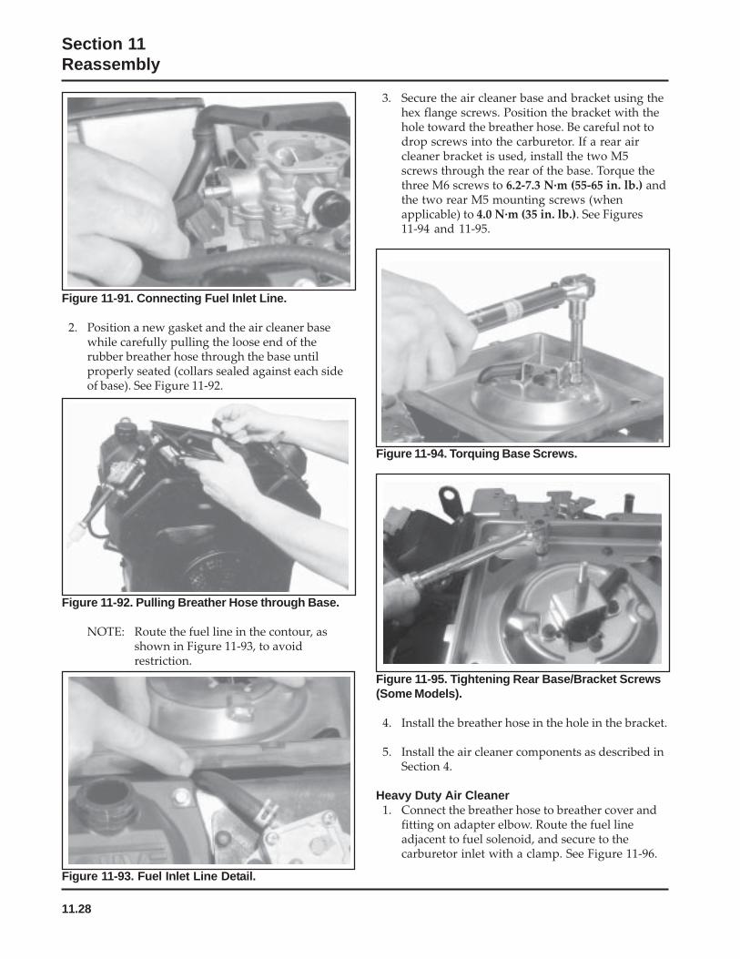
11.28
Section 11Reassembly
Figure 11-91. Connecting Fuel Inlet Line.
2. Position a new gasket and the air cleaner basewhile carefully pulling the loose end of therubber breather hose through the base untilproperly seated (collars sealed against each sideof base). See Figure 11-92.
Figure 11-92. Pulling Breather Hose through Base.
NOTE: Route the fuel line in the contour, asshown in Figure 11-93, to avoidrestriction.
3. Secure the air cleaner base and bracket using thehex flange screws. Position the bracket with thehole toward the breather hose. Be careful not todrop screws into the carburetor. If a rear aircleaner bracket is used, install the two M5screws through the rear of the base. Torque thethree M6 screws to 6.2-7.3 N·m (55-65 in. lb.) andthe two rear M5 mounting screws (whenapplicable) to 4.0 N·m (35 in. lb.). See Figures11-94 and 11-95.
Figure 11-93. Fuel Inlet Line Detail.
Figure 11-94. Torquing Base Screws.
Figure 11-95. Tightening Rear Base/Bracket Screws(Some Models).
4. Install the breather hose in the hole in the bracket.
5. Install the air cleaner components as described inSection 4.
Heavy Duty Air Cleaner1. Connect the breather hose to breather cover and
fitting on adapter elbow. Route the fuel lineadjacent to fuel solenoid, and secure to thecarburetor inlet with a clamp. See Figure 11-96.
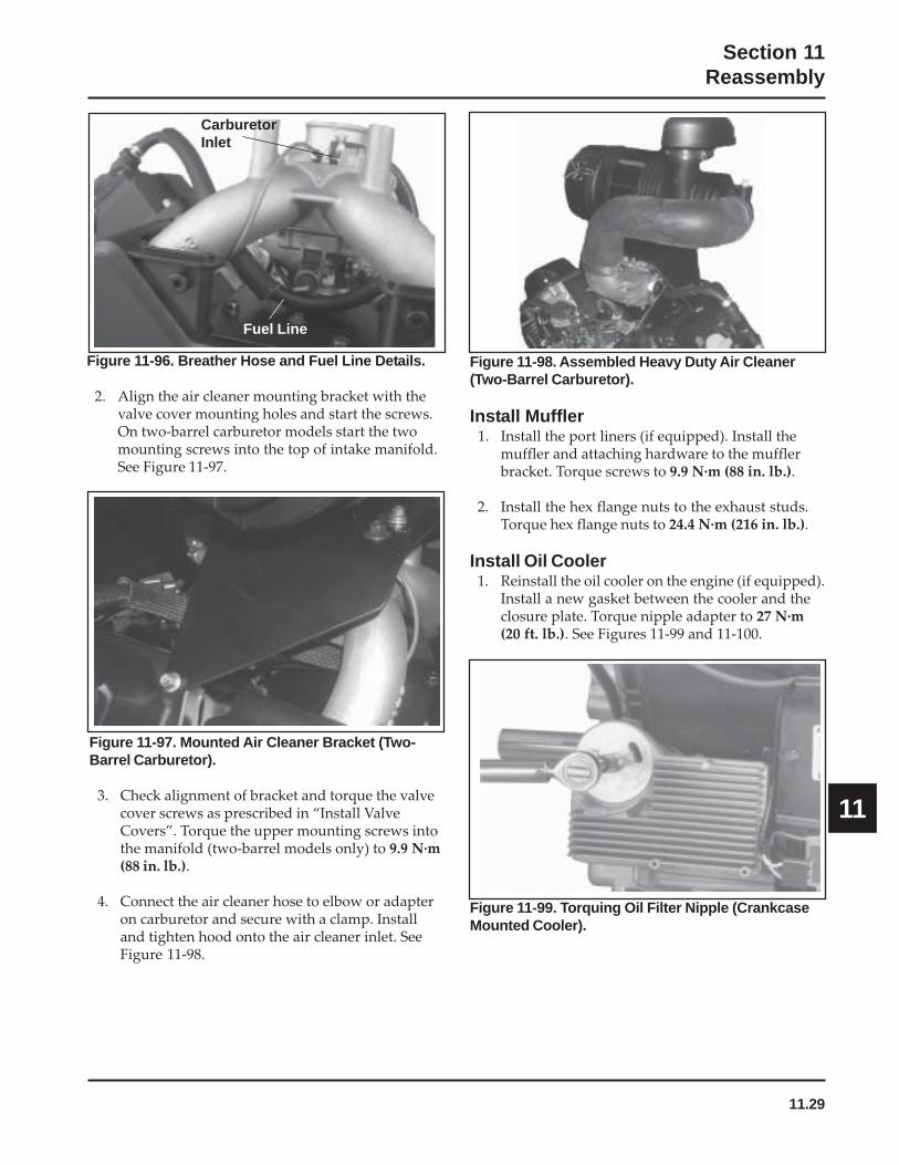
11.29
Section 11Reassembly
11
Figure 11-96. Breather Hose and Fuel Line Details.
2. Align the air cleaner mounting bracket with thevalve cover mounting holes and start the screws.On two-barrel carburetor models start the twomounting screws into the top of intake manifold.See Figure 11-97.
Figure 11-97. Mounted Air Cleaner Bracket (Two-Barrel Carburetor).
3. Check alignment of bracket and torque the valvecover screws as prescribed in “Install ValveCovers”. Torque the upper mounting screws intothe manifold (two-barrel models only) to 9.9 N·m(88 in. lb.).
4. Connect the air cleaner hose to elbow or adapteron carburetor and secure with a clamp. Installand tighten hood onto the air cleaner inlet. SeeFigure 11-98.
Figure 11-98. Assembled Heavy Duty Air Cleaner(Two-Barrel Carburetor).
Install Muffler1. Install the port liners (if equipped). Install the
muffler and attaching hardware to the mufflerbracket. Torque screws to 9.9 N·m (88 in. lb.).
2. Install the hex flange nuts to the exhaust studs.Torque hex flange nuts to 24.4 N·m (216 in. lb.).
Install Oil Cooler1. Reinstall the oil cooler on the engine (if equipped).
Install a new gasket between the cooler and theclosure plate. Torque nipple adapter to 27 N·m(20 ft. lb.). See Figures 11-99 and 11-100.
Figure 11-99. Torquing Oil Filter Nipple (CrankcaseMounted Cooler).
CarburetorInlet
Fuel Line

11.30
Section 11Reassembly
Figure 11-101. Installing New Oil Filter.
3. Hand tighten the filter until the rubber gasketcontacts the adapter, then tighten the filter anadditional 3/4-1 turn. See Figure 11-102.
Figure 11-103. Reinstall and Torque Both Oil DrainPlugs.
5. Add oil to bring the level up to “F” mark andreinstall the dipstick. See Figure 11-104.
Figure 11-100. Mounting Oil Cooler (Blower HousingMounted Cooler).
Install Oil Filter and Fill Crankcase with Oil1. Prefill a new oil filter following the instructions
in Section 6.
2. Apply a thin film of clean engine oil to the rubbergasket on the oil filter and thread the filter ontothe adapter nipple. See Figure 11-101.
Figure 11-102. Hand Tightening Oil Filter.
4. Install the oil drain plugs. See Figure 11-103.Torque the plugs to 13.6 N·m (10 ft. lb.).
NOTE: Make sure that both oil drain plugs areinstalled and torqued to the abovespecifications to prevent oil leakage.
Mounting Locations
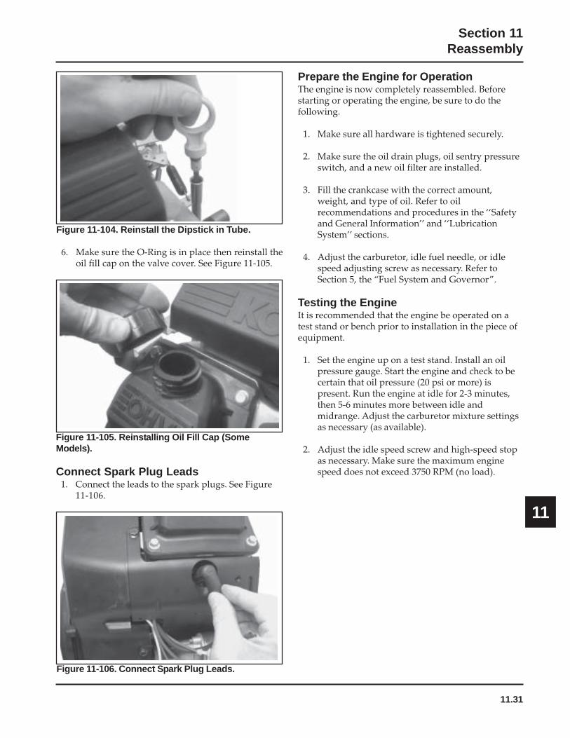
11.31
Section 11Reassembly
11
Figure 11-104. Reinstall the Dipstick in Tube.
6. Make sure the O-Ring is in place then reinstall theoil fill cap on the valve cover. See Figure 11-105.
Figure 11-105. Reinstalling Oil Fill Cap (SomeModels).
Connect Spark Plug Leads1. Connect the leads to the spark plugs. See Figure
11-106.
Figure 11-106. Connect Spark Plug Leads.
Prepare the Engine for OperationThe engine is now completely reassembled. Beforestarting or operating the engine, be sure to do thefollowing.
1. Make sure all hardware is tightened securely.
2. Make sure the oil drain plugs, oil sentry pressureswitch, and a new oil filter are installed.
3. Fill the crankcase with the correct amount,weight, and type of oil. Refer to oilrecommendations and procedures in the ‘‘Safetyand General Information’’ and ‘‘LubricationSystem’’ sections.
4. Adjust the carburetor, idle fuel needle, or idlespeed adjusting screw as necessary. Refer toSection 5, the “Fuel System and Governor”.
Testing the EngineIt is recommended that the engine be operated on atest stand or bench prior to installation in the piece ofequipment.
1. Set the engine up on a test stand. Install an oilpressure gauge. Start the engine and check to becertain that oil pressure (20 psi or more) ispresent. Run the engine at idle for 2-3 minutes,then 5-6 minutes more between idle andmidrange. Adjust the carburetor mixture settingsas necessary (as available).
2. Adjust the idle speed screw and high-speed stopas necessary. Make sure the maximum enginespeed does not exceed 3750 RPM (no load).
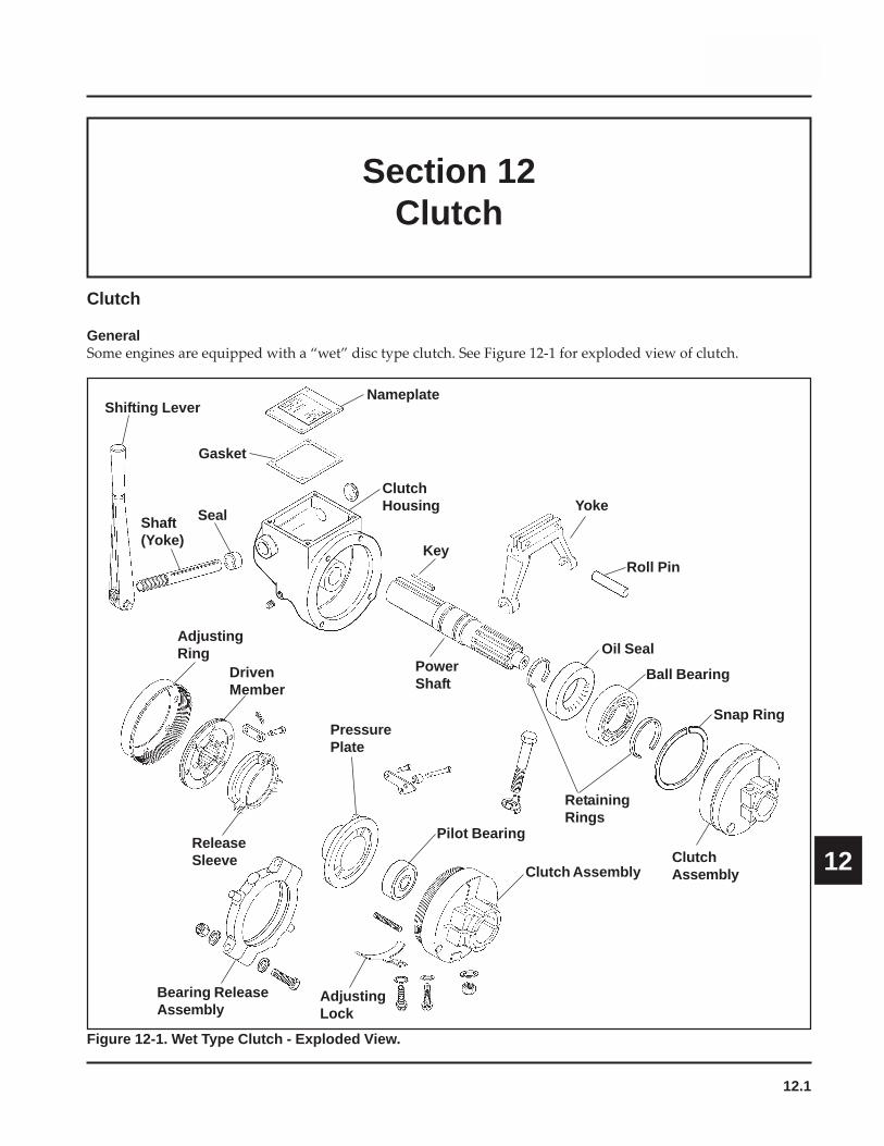
12.1
Section 12Clutch
12
Section 12Clutch
Clutch
GeneralSome engines are equipped with a “wet” disc type clutch. See Figure 12-1 for exploded view of clutch.
Figure 12-1. Wet Type Clutch - Exploded View.
Nameplate
Gasket
Shifting Lever
SealShaft(Yoke)
ClutchHousing
Key
Yoke
Roll Pin
Ball BearingPowerShaft
AdjustingRing
DrivenMember
ClutchAssembly
Pilot Bearing
PressurePlate
ReleaseSleeve
Clutch Assembly
AdjustingLock
Bearing ReleaseAssembly
Oil Seal
RetainingRings
Snap Ring
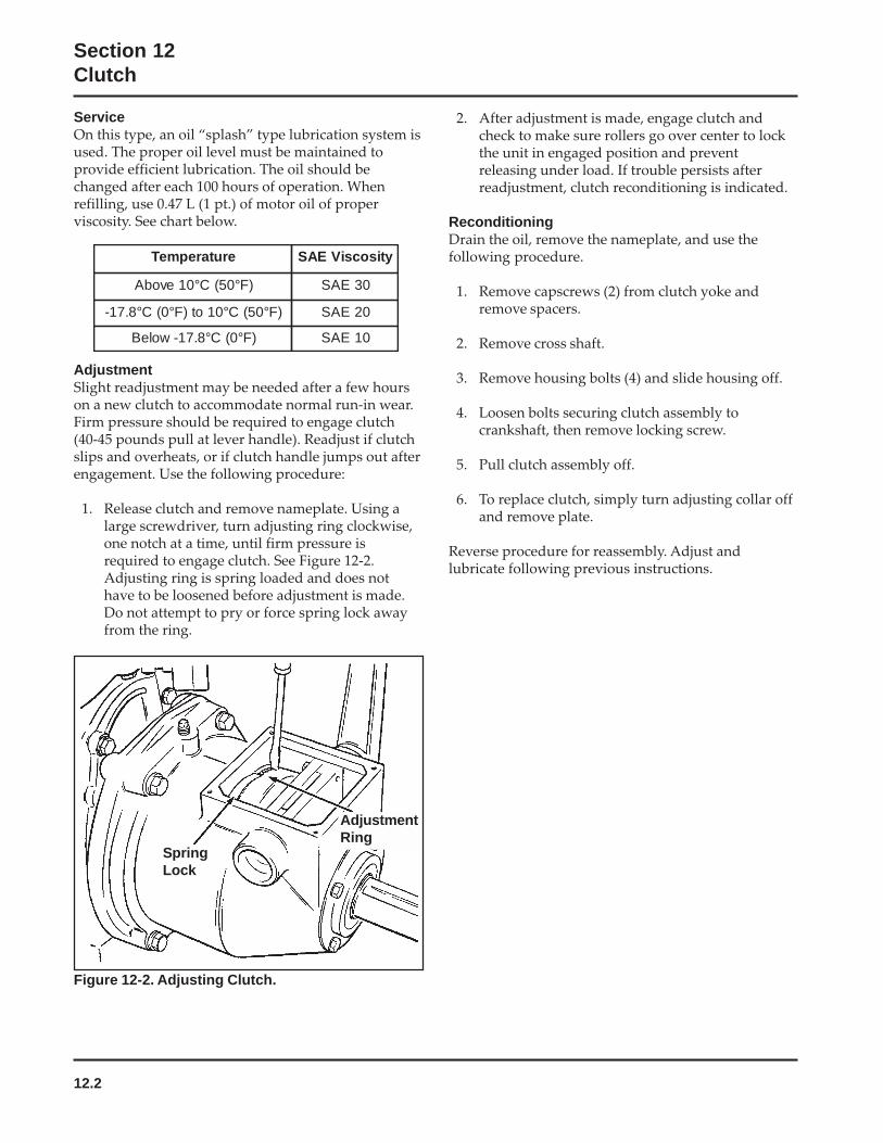
12.2
Section 12Clutch
ServiceOn this type, an oil “splash” type lubrication system isused. The proper oil level must be maintained toprovide efficient lubrication. The oil should bechanged after each 100 hours of operation. Whenrefilling, use 0.47 L (1 pt.) of motor oil of properviscosity. See chart below.
2. After adjustment is made, engage clutch andcheck to make sure rollers go over center to lockthe unit in engaged position and preventreleasing under load. If trouble persists afterreadjustment, clutch reconditioning is indicated.
ReconditioningDrain the oil, remove the nameplate, and use thefollowing procedure.
1. Remove capscrews (2) from clutch yoke andremove spacers.
2. Remove cross shaft.
3. Remove housing bolts (4) and slide housing off.
4. Loosen bolts securing clutch assembly tocrankshaft, then remove locking screw.
5. Pull clutch assembly off.
6. To replace clutch, simply turn adjusting collar offand remove plate.
Reverse procedure for reassembly. Adjust andlubricate following previous instructions.
AdjustmentSlight readjustment may be needed after a few hourson a new clutch to accommodate normal run-in wear.Firm pressure should be required to engage clutch(40-45 pounds pull at lever handle). Readjust if clutchslips and overheats, or if clutch handle jumps out afterengagement. Use the following procedure:
1. Release clutch and remove nameplate. Using alarge screwdriver, turn adjusting ring clockwise,one notch at a time, until firm pressure isrequired to engage clutch. See Figure 12-2.Adjusting ring is spring loaded and does nothave to be loosened before adjustment is made.Do not attempt to pry or force spring lock awayfrom the ring.
Figure 12-2. Adjusting Clutch.
AdjustmentRing
SpringLock
erutarepmeT ytisocsiVEAS
)F°05(C°01evobA 03EAS
)F°05(C°01ot)F°0(C°8.71- 02EAS
)F°0(C°8.71-woleB 01EAS

LITHO IN U.S.A.
FORM NO.: TP-2428-C
ISSUED: 4/92
REVISED: 3/06
ENGINE DIVISION, KOHLER CO., KOHLER, WISCONSIN 53044
FOR SALES AND SERVICE INFORMATIONIN U.S. AND CANADA, CALL 1-800-544-2444