kodak home page on internet intranet table of...
TRANSCRIPT

Kodak Home Pageon Internet
Intranet
Table of Contents
© Eastman Kodak Company, 1999
{ServiceManual}{Production}{KodakServiceSupport}
Publication No. SM4530-130APR96
SERVICE MANUALfor the
Kodak Ektagraphic IIIPAINTED and NON-PAINTED PROJECTORS
Models A, KKA, JA, ATS, AM, AMT, JAMT, B, BR, E,E-PLUS SLIDE, J-E PLUS, and KKE PLUS
A100_0001HA

2 30APR96 – SM4530-1
PLEASE NOTE The information contained herein is based on the experience and knowledge relating to thesubject matter gained by Eastman Kodak Company prior to publication.
No patent license is granted by this information.
Eastman Kodak Company reserves the right to change this information without notice, andmakes no warranty, express or implied, with respect to this information. Kodak shall not be liablefor any loss or damage, including consequential or special damages, resulting from any use ofthis information, even if loss or damage is caused by Kodak’s negligence or other fault.
This equipment includes parts and assemblies sensitive to damage from electrostaticdischarge. Use caution to prevent damage during all service procedures.
Description Page
Table of Contents
Replacements and Installations . . . . . . . . . . . . . . . . . . . . . . . . . . . . . . . . . . . . . . . . . . . . 4Replacing the LOWER HOUSING ASSEMBLY. . . . . . . . . . . . . . . . . . . . . . . . . 4Installing the LOWER HOUSING ASSEMBLY. . . . . . . . . . . . . . . . . . . . . . . . . . 4Replacing the FAN SHAFT ASSEMBLY . . . . . . . . . . . . . . . . . . . . . . . . . . . . . . 5Installing the FAN SHAFT ASSEMBLY . . . . . . . . . . . . . . . . . . . . . . . . . . . . . . . 7Replacing the MOTOR. . . . . . . . . . . . . . . . . . . . . . . . . . . . . . . . . . . . . . . . . . . . 7Installing the MOTOR. . . . . . . . . . . . . . . . . . . . . . . . . . . . . . . . . . . . . . . . . . . . . 8Replacing the WORM PULLEY and MECHANISM BELT . . . . . . . . . . . . . . . . . 8Installing the WORM PULLEY and MECHANISM BELT . . . . . . . . . . . . . . . . . . 9Replacing the THERMAL FUSE ASSEMBLY . . . . . . . . . . . . . . . . . . . . . . . . . . 9Installing the THERMAL FUSE ASSEMBLY . . . . . . . . . . . . . . . . . . . . . . . . . . . 10Replacing the LAMP MODULE RECEPTACLE . . . . . . . . . . . . . . . . . . . . . . . . . 11Installing the LAMP MODULE RECEPTACLE. . . . . . . . . . . . . . . . . . . . . . . . . . 11Replacing the CYCLE SOLENOID ASSEMBLY . . . . . . . . . . . . . . . . . . . . . . . . 12Installing the CYCLE SOLENOID ASSEMBLY . . . . . . . . . . . . . . . . . . . . . . . . . 12Replacing the MECHANISM ASSEMBLY . . . . . . . . . . . . . . . . . . . . . . . . . . . . . 13Installing the MECHANISM ASSEMBLY . . . . . . . . . . . . . . . . . . . . . . . . . . . . . . 14Replacing the AUTO-FOCUS BRACKET ASSEMBLY . . . . . . . . . . . . . . . . . . . 14Installing the AUTO-FOCUS BRACKET ASSEMBLY . . . . . . . . . . . . . . . . . . . . 14Replacing the CAM STACK ASSEMBLY and CYCLE LEVER ASSEMBLY . . . 15Installing the CAM STACK ASSEMBLY and CYCLE LEVER ASSEMBLY . . . . 17Replacing the LAMP SOCKET TERMINAL ASSEMBLY, N.P. . . . . . . . . . . . . . 18Installing the LAMP SOCKET TERMINAL ASSEMBLY. . . . . . . . . . . . . . . . . . . 18Replacing the LAMP SOCKET TERMINAL ASSEMBLY, Painted Models . . . . 19Installing the LAMP SOCKET TERMINAL ASSEMBLY, Painted Models . . . . . 20Replacing the LENS MOUNT ASSEMBLY - Auto Focus Model . . . . . . . . . . . . 20Installing the LENS MOUNT ASSEMBLY - Auto Focus Models . . . . . . . . . . . . 20Replacing the LENS MOUNT ASSEMBLY - Non Auto Focus Model. . . . . . . . . 21Installing the LENS MOUNT ASSEMBLY - Non Auto Focus Model . . . . . . . . . 21Replacing the AUTO-FOCUS SWITCH ASSEMBLY. . . . . . . . . . . . . . . . . . . . . 22Installing the AUTO-FOCUS SWITCH ASSEMBLY. . . . . . . . . . . . . . . . . . . . . . 22Replacing the FOCUS SHAFT ASSEMBLY - Auto Focus Models. . . . . . . . . . . 23Installing the FOCUS SHAFT ASSEMBLY . . . . . . . . . . . . . . . . . . . . . . . . . . . . 24Replacing the FOCUS SHAFT ASSEMBLY - Non Auto-Focus Models. . . . . . . 24Installing the FOCUS SHAFT ASSEMBLY . . . . . . . . . . . . . . . . . . . . . . . . . . . . 25
Adjustments . . . . . . . . . . . . . . . . . . . . . . . . . . . . . . . . . . . . . . . . . . . . . . . . . . . . . . . . . . . 26Adjusting the CYCLE SOLENOID . . . . . . . . . . . . . . . . . . . . . . . . . . . . . . . . . . . 26Adjusting the INDEXER LEVER ASSEMBLY . . . . . . . . . . . . . . . . . . . . . . . . . . 27Adjusting the SLIDE LIFT LEVER MANUAL . . . . . . . . . . . . . . . . . . . . . . . . . . . 28

SM4530-1 – 30APR96 3
Adjusting the SLIDE LIFT LEVER POWER . . . . . . . . . . . . . . . . . . . . . . . . . . . . 29Adjusting the ZERO POSITION SWITCH. . . . . . . . . . . . . . . . . . . . . . . . . . . . . . 30Adjusting the Focus Light Path - Auto Focus Models . . . . . . . . . . . . . . . . . . . . . 31Adjusting the NULL. . . . . . . . . . . . . . . . . . . . . . . . . . . . . . . . . . . . . . . . . . . . . . . 32Adjusting the PHOTOCELL . . . . . . . . . . . . . . . . . . . . . . . . . . . . . . . . . . . . . . . . 33Adjusting the CLAMP PAD ASSEMBLY. . . . . . . . . . . . . . . . . . . . . . . . . . . . . . . 35Adjusting the DARK SHUTTER . . . . . . . . . . . . . . . . . . . . . . . . . . . . . . . . . . . . . 36
Lubrication . . . . . . . . . . . . . . . . . . . . . . . . . . . . . . . . . . . . . . . . . . . . . . . . . . . . . . . . . . . . . 37Tools . . . . . . . . . . . . . . . . . . . . . . . . . . . . . . . . . . . . . . . . . . . . . . . . . . . . . . . . . . . . . . . . . 40Specifications . . . . . . . . . . . . . . . . . . . . . . . . . . . . . . . . . . . . . . . . . . . . . . . . . . . . . . . . . . 41Diagnostics . . . . . . . . . . . . . . . . . . . . . . . . . . . . . . . . . . . . . . . . . . . . . . . . . . . . . . . . . . . . 43
MAIN MOTOR Voltages . . . . . . . . . . . . . . . . . . . . . . . . . . . . . . . . . . . . . . . . . . . 439-PIN SPECIAL APPLICATION PLUG. . . . . . . . . . . . . . . . . . . . . . . . . . . . . . . . 44PHOTOCELL Voltages . . . . . . . . . . . . . . . . . . . . . . . . . . . . . . . . . . . . . . . . . . . . 445-PIN REMOTE CORD PLUG Voltages. . . . . . . . . . . . . . . . . . . . . . . . . . . . . . . 45SMALL COMPONENT BOARD ASSEMBLY 256809 Voltages . . . . . . . . . . . . . 46Voltage Specifications - General Parts . . . . . . . . . . . . . . . . . . . . . . . . . . . . . . . . 47Power, Illumination, and Cooling Malfunctions . . . . . . . . . . . . . . . . . . . . . . . . . . 47Slide Transport Malfunctions . . . . . . . . . . . . . . . . . . . . . . . . . . . . . . . . . . . . . . . 48Focus Malfunctions. . . . . . . . . . . . . . . . . . . . . . . . . . . . . . . . . . . . . . . . . . . . . . . 51

SERVICE MANUAL
4 30APR96 – SM4530-1
Section 1: Replacements and Installations
Replacing the LOWER HOUSING ASSEMBLY
WarningDangerous Voltage
[1] Disconnect the main power.
[2] Remove the PROJECTION LENS.
[3] Remove the LAMP MODULE ASSEMBLY.
[4] Remove the 6 Torx SCREWS (for N.P. models) (or 6 Phillips SCREWS for Painted Models) from the LOWERHOUSING ASSEMBLY.
[5] Pull the LOWER HOUSING ASSEMBLY off the TOP HOUSING.
Installing the LOWER HOUSING ASSEMBLY
[1] Do the replacement procedure for the LOWER HOUSING ASSEMBLY in reverse order.
A100_0012HA LAMP MODULE
LOWER HOUSING
SCREW (6)
A100_0012HCA

Replacements and Installations
SM4530-1 – 30APR96 5
Replacing the FAN SHAFT ASSEMBLY
WarningDangerous Voltage
[1] Disconnect the main power.
[2] Do the replacement procedure for the LOWER HOUSING ASSEMBLY.
[3] Cut the 3 WIRE TIES:
• 1 on BLOWER COVER wires
• 2 on SMALL CIRCUIT BOARD between the MOTOR and MECHANISM ASSEMBLY
[4] Disconnect the 2 wires from the CYCLE SOLENOID on the SMALL CIRCUIT BOARD.
[5] Pull the SMALL CIRCUIT BOARD up.
[6] Remove the Torx SCREW from the BLOWER COVER ASSEMBLY.
[7] Lift the GRILLE ASSEMBLY in front of the BLOWER COVER ASSEMBLY up.
[8] Loosen the Torx SCREW on the right track of the LOWER LIGHT BAFFLE ASSEMBLY appoximately half way.
[9] Lift the LOWER LIGHT BAFFLE ASSEMBLY off the TAB on the BLOWER COVER ASSEMBLY.
[10] Remove the 2 long Torx SCREWS from the BLOWER COVER ASSEMBLY.
A100_0013HA
BR and KK models
A100_0013HCA
WIRE TIE (not shown)
BLOWER COVER WIRE TIE
GRILLE ASSEMBLY

SERVICE MANUAL
6 30APR96 – SM4530-1
[11] Lift the BLOWER COVER ASSEMBLY up.
[12] Remove the 3 Hex 1/4 in. SCREWS from the MOTOR.
[13] Lift the MOTOR until you observe the FAN BELT and MECHANISM BELT.
[14] Remove the FAN BELT and MECHANISM BELT off the MOTOR PULLEY. Use SPRING HOOK TL-1165.
CautionMove the MOTOR to allow access to the parts; wires are still connected to the MOTOR. Do not cause damage tothe MOTOR wires.
[15] N.P. only: Remove the RETAINER CLIP from the FAN SHAFT.
[16] Painted Models only: Remove the FAN CAP, E-RING, SPRING, and WASHER.
[17] Pull the FAN up and off the FAN SHAFT to allow access to the FAN BELT.
[18] Remove the FAN BELT.
[19] N.P. only: Remove the 3 Torx SCREWS from the FAN SHAFT ASSEMBLY.
[20] Lift and remove the FAN SHAFT ASSEMBLY.
A008_0172HA
CORKWASHER
MOTOR SCREW
MECHANISMBELT
RETAINERCLIP
FAN
FAN PLATEASSEMBLY
FANBELT SCREW (3)
BLOWERASSEMBLY
FAN CAP
E-RING
SPRING
WASHERFAN
SCREW WASHER
FAN PLATE
Painted PROJECTOR
A008_0172HCA

Replacements and Installations
SM4530-1 – 30APR96 7
Installing the FAN SHAFT ASSEMBLY
ImportantWhen installing the FAN and MECHANISM BELTS, install the MECHANISM BELT on the small MOTOR PULLEY,and the FAN BELT on the large MOTOR PULLEY.
[1] Do the removal procedure for the FAN BELT and SHAFT in reverse order.
Replacing the MOTOR
WarningDangerous Voltage
[1] Disconnect the main power.
[2] Do the replacement procedure for the LOWERHOUSING ASSEMBLY.
[3] Disconnect all wires from the MOTOR.
[4] Cut the 2 WIRE TIES on the SMALL CIRCUITBOARD between the MOTOR and MECHANISMASSEMBLY.
[5] Disconnect the 2 wires from the CYCLESOLENOID on the SMALL CIRCUIT BOARD.
[6] Pull the SMALL CIRCUIT BOARD up.
[7] Disconnect all wires on the MOTOR.
[8] Remove 3 Hex 1/4 in. SCREWS from the MOTOR.
[9] Lift the MOTOR up to allow access to the FAN andMECHANISM BELTS.
[10] Remove the FAN and MECHANISM BELTS fromthe MOTOR PULLEY.
[11] Remove the MOTOR.
A091_4015BAA091_4015BCAMECHANISM BELTFAN BELT
A091_4016GA
MOTOR
SCREW (3)
A091_4016GCA

SERVICE MANUAL
8 30APR96 – SM4530-1
Installing the MOTOR
ImportantWhen installing the FAN and MECHANISM BELTS, install the MECHANISM BELT on the small MOTOR PULLEY,and the FAN BELT on the large MOTOR PULLEY.
[1] Do the replacement procedure for the MOTOR in reverse order.
Replacing the WORM PULLEY and MECHANISM BELT
WarningDangerous Voltage
[1] Disconnect the main power.
[2] Do the replacement procedure for the LOWERHOUSING ASSEMBLY.
[3] Do the replacement procedure for the MOTORexcept do not disconnect the wires from theMOTOR.
[4] Remove the Torx SCREW (on N.P. models) (orHex SCREW on Painted Models) from the WORMPULLEY ASSEMBLY.
[5] Move the TAB on the WORM PULLEYASSEMBLY out.
[6] Remove the WORM PULLEY ASSEMBLY andMECHANISM BELT.
A091_4015BAA091_4015BCAMECHANISM BELTFAN BELT
A091_4017GA
WORM PULLEY
BELTMECHANISM
A091_4017GCA
SCREW

Replacements and Installations
SM4530-1 – 30APR96 9
Installing the WORM PULLEY and MECHANISM BELT
ImportantWhen installing the FAN and MECHANISM BELTS, install the MECHANISM BELT on the small MOTOR PULLEY,and the FAN BELT on the large MOTOR PULLEY.
[1] Do the replacement procedure for the WORM PULLEY and MECHANISM BELT in reverse order.
Replacing the THERMAL FUSE ASSEMBLY
WarningDangerous Voltage
[1] Disconnect the main power.
[2] Do the replacement procedure for the LOWER HOUSING ASSEMBLY.
[3] Cut and remove the necessary WIRE TIES.
[4] Remove the black wire from the THERMAL FUSE ASSEMBLY on the POWER SWITCH.
[5] Remove the gray wire from the THERMAL FUSE ASSEMBLY from the POWER CORD.
[6] Loosen the Torx SCREW on the PREHEAT DUCT approximately half way.
[7] Pull the THERMAL FUSE ASSEMBLY out of hole of the LOWER LIGHT BAFFLE ASSEMBLY.
A091_4015BAA091_4015BCAMECHANISM BELTFAN BELT

SERVICE MANUAL
10 30APR96 – SM4530-1
Installing the THERMAL FUSE ASSEMBLY
[1] Do the replacement procedure for the THERMALFUSE ASSEMBLY in reverse order.
A100_0015GA
SCREW
PRE-HEAT DUCT
THERMAL FUSE
POWER SWITCHA100_0015GCA
Replacements and Installations
SM4530-1 – 30APR96 11
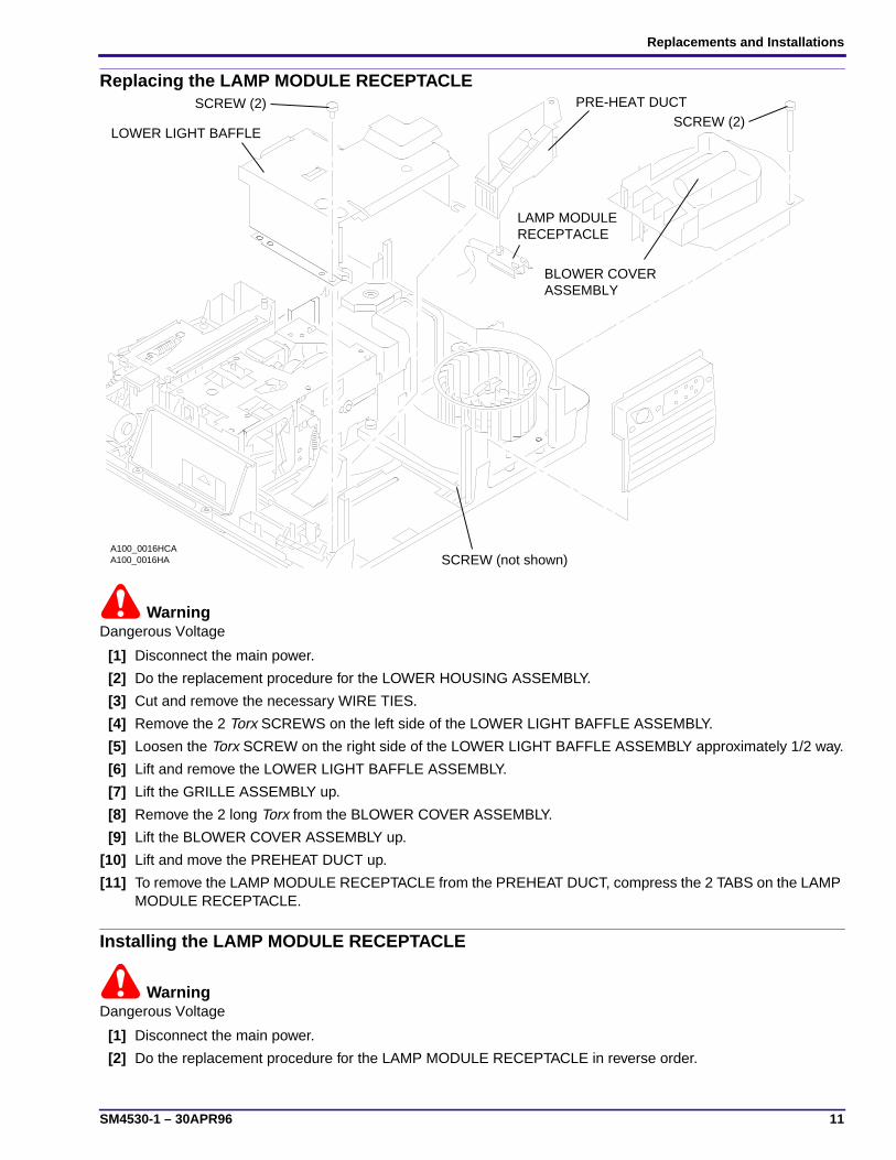
Replacing the LAMP MODULE RECEPTACLE
WarningDangerous Voltage
[1] Disconnect the main power.
[2] Do the replacement procedure for the LOWER HOUSING ASSEMBLY.
[3] Cut and remove the necessary WIRE TIES.
[4] Remove the 2 Torx SCREWS on the left side of the LOWER LIGHT BAFFLE ASSEMBLY.
[5] Loosen the Torx SCREW on the right side of the LOWER LIGHT BAFFLE ASSEMBLY approximately 1/2 way.
[6] Lift and remove the LOWER LIGHT BAFFLE ASSEMBLY.
[7] Lift the GRILLE ASSEMBLY up.
[8] Remove the 2 long Torx from the BLOWER COVER ASSEMBLY.
[9] Lift the BLOWER COVER ASSEMBLY up.
[10] Lift and move the PREHEAT DUCT up.
[11] To remove the LAMP MODULE RECEPTACLE from the PREHEAT DUCT, compress the 2 TABS on the LAMPMODULE RECEPTACLE.
Installing the LAMP MODULE RECEPTACLE
WarningDangerous Voltage
[1] Disconnect the main power.
[2] Do the replacement procedure for the LAMP MODULE RECEPTACLE in reverse order.
A100_0016HA SCREW (not shown)
RECEPTACLELAMP MODULE
ASSEMBLYBLOWER COVER
SCREW (2)PRE-HEAT DUCTSCREW (2)
LOWER LIGHT BAFFLE
A100_0016HCA

SERVICE MANUAL
12 30APR96 – SM4530-1
Replacing the CYCLE SOLENOID ASSEMBLY
WarningDangerous Voltage
[1] Disconnect the main power.
[2] Do the replacement procedures for the LOWERHOUSING ASSEMBLY and the MOTOR.
[3] Cut and remove the necessary WIRE TIES.
[4] Disconnect the 2 wires from the CYCLESOLENOID on the SMALL CIRCUIT BOARD.
[5] Pull the SMALL CIRCUIT BOARD up.
[6] Remove the Torx SCREW (for N.P. models) (orHex SCREW for Painted Models) from the WORMPULLEY SHAFT.
[7] Move the TAB on the WORM PULLEYASSEMBLY out of the MECHANISM ASSEMBLY.
[8] Lift and remove the WORM PULLEY ASSEMBLY.
[9] Remove the 2 Torx 1/4 in. SCREWS from the 2CYCLE SOLENOID GROMMETS.
[10] Pull the CYCLE SOLENOID ASSEMBLY up andout.
[11] If necessary, remove the CYCLE SOLENOIDPLUNGER ASSEMBLY.
Installing the CYCLE SOLENOID ASSEMBLY
ImportantDo the adjustment for the CYCLE SOLENOID ASSEMBLY. See the Adjustments section.
[1] Do the replacement procedure for the CYCLE SOLENOID ASSEMBLY in reverse order.
A100_0017GA
PLUNGERSOLENOIDCYCLE
CYCLE SOLENOID SCREW (2)
A100_0017GCA

Replacements and Installations
SM4530-1 – 30APR96 13
Replacing the MECHANISM ASSEMBLY
WarningDangerous Voltage
[1] Disconnect the main power.
[2] Do the replacement procedure for the LOWERHOUSING ASSEMBLY.
[3] Cut and remove the necessary WIRE TIES.
[4] Disconnect the 2 wires from the CYCLESOLENOID on the SMALL CIRCUIT BOARD.
[5] Pull the SMALL CIRCUIT BOARD up.
[6] Disconnect all wires connected to theMECHANISM ASSEMBLY:
• 1 yellow wire from CYCLE SWITCH
• 1 orange wire from WIRE NUT
• 1 green wire from POWER CORD
• 2 green ground wires from the lowerMECHANISM ASSEMBLY
[7] Remove the FOCUS KNOB from the FRONTPANEL.
ImportantFor Auto-Focus models only, disconnect the short, graywire connected to the AUTO-FOCUS DEFEATSWITCH.
[8] Remove the 3 Torx SCREWS from the LENSMOUNT ASSEMBLY.
[9] Lift and move the LENS MOUNT ASSEMBLY up.
[10] Do the replacement procedure for the MOTOR.
[11] Remove the 3 Torx SCREWS from theMECHANISM ASSEMBLY.
[12] Loosen the SCREW on the STABILIZER WALLapproximately half way.
[13] Remove the SCREW from the DARK SHUTTERSWITCH and remove the SWITCH.
CautionThere might be a bind between the SELECT LEVERand the SELECT BUTTON when removing theMECHANISM ASSEMBLY. Do not use force; thismight cause damage to the SELECT BUTTON.
[14] Remove the MECHANISM ASSEMBLY.
A091_4022CA
SWITCH
DARKSHUTTER
ASSEMBLYMECHANISM
(not shown)DEFEAT SWITCHAUTO FOCUS
FOCUS KNOB
A091_4022CCA
SCREW
MOUNTLENS
SCREW (3) SCREW

SERVICE MANUAL
14 30APR96 – SM4530-1
Installing the MECHANISM ASSEMBLY
ImportantTo insert the SELECT BUTTON into the hole in the SELECT LEVER when installing the MECHANISM ASSEMBLY,hold the SELECT BUTTON completely down.
[1] Do the removal procedure for the MECHANISM ASSEMBLY in reverse order.
Replacing the AUTO-FOCUS BRACKET ASSEMBLY
WarningDangerous Voltage
[1] Disconnect the main power.
[2] Do the replacement procedure for the LOWER HOUSING ASSEMBLY.
[3] Cut and remove the necessary WIRE TIES.
[4] Disconnect the 2 wires from the CYCLE SOLENOID on the SMALL CIRCUIT BOARD.
[5] Pull the SMALL CIRCUIT BOARD up.
[6] Do the replacement procedure for the MECHANISM ASSEMBLY.
[7] Remove the Torx SCREW (on N.P. models) (or Hex SCREW on Painted Models) from the WORM PULLEY.
[8] Remove the WORM PULLEY.
[9] Remove the 2 Hex SCREWS from the CYCLE SOLENOID.
[10] Remove the CYCLE SOLENOID.
[11] Remove the Phillips SCREW from the AUTO-FOCUS BRACKET ASSEMBLY.
[12] Pull and remove the AUTO-FOCUS BRACKET ASSEMBLY through the hole where the CYCLE SOLENOIDwas.
Installing the AUTO-FOCUS BRACKET ASSEMBLY[1] Do the replacement procedure for the AUTO-FOCUS BRACKET ASSEMBLY in reverse order.
A091_4023BASOLENOIDCYCLE
SCREW
ASSEMBLYBRACKETFOCUSAUTO
SCREW (2)
SCREWA091_4023BCA
PULLEYWORM

Replacements and Installations
SM4530-1 – 30APR96 15
Replacing the CAM STACK ASSEMBLY and CYCLE LEVER ASSEMBLY
WarningDangerous Voltage
[1] Disconnect the main power.
[2] Do the replacement procedure for the MECHANISM ASSEMBLY.
[3] Remove the INDEXER LEVER ASSEMBLY from the TOP PLATE of the MECHANISM ASSEMBLY.
[4] Remove the Torx SCREW (on N.P. models) (or Hex SCREW on Painted Models) from the WORM PULLEYASSEMBLY.
[5] Remove the WORM PULLEY ASSEMBLY.
[6] Remove the DIRECTION LEVER LINK from the DIRECTION LEVER.
[7] Remove the DIRECTION LEVER SPRING from the DIRECTION LEVER.
[8] Disconnect the LIFT LEVER SPRING from LIFT LEVER on the TOP PLATE of the MECHANISM ASSEMBLY.
[9] Remove the RETARD SPRING.
[10] Remove the 7 Torx SCREWS (on N.P. models) (or Hex SCREWS on Painted Models) from the TOP PLATE ofthe MECHANISM ASSEMBLY.
[11] Remove the TOP PLATE.
A008_0173HAA008_0173HCA
SPRINGRETARDSTYLE 2
BEARING
E-RING
SPRINGRETARDSTYLE 1
SHAFTLIFT LEVER LIFT LEVER
BEARING
E-RING
NUT
CAM STACK ASSEMBLY

SERVICE MANUAL
16 30APR96 – SM4530-1
[12] Remove the LIGHT BAFFLE.
[13] Remove the NUT from the LIFT LEVER SHAFT.
[14] Remove the LIFT LEVER and SHAFT.
[15] Remove the 2 E-RINGS from the 2 CAM SHAFT BEARINGS.
[16] Remove the 2 CAM SHAFT BEARINGS.
[17] Press and hold the SELECT LEVER down.
[18] Remove the CAM STACK ASSEMBLY.
[19] Disconnect the SELECT LEVER SPRING from the TAB and remove the SELECT LEVER.
A008_0174HAA008_0174HCA
SELECT LEVER
SPRINGLEVERSELECT
TABCAM STACK ASSEMBLY
NUT
E-RING
BEARING
LIFT LEVERLIFT LEVERSHAFT
E-RING
BEARING

Replacements and Installations
SM4530-1 – 30APR96 17
[20] Remove the 2 SCREWS from the CYCLESOLENOID.
[21] Remove the CYCLE SOLENOID.
[22] Slide the PLUNGER and PLUNGER SPRING offthe CYCLE LEVER.
[23] Remove the HALF CYCLE SPRING between theCYCLE LEVER ASSEMBLY and the HALFCYCLE LEVER.
[24] Disconnect the INDEX LEVER SPRING from theMECHANISM ASSEMBLY.
[25] Push the INDEX LEVER back.
[26] Remove the 2 E-RINGS:
• 1 on the CYCLE LEVER ASSEMBLY
• 1 on the HALF CYCLE LEVER
CautionKeep both the CYCLE LEVER ASSEMBLY and theHALF CYCLE LEVER together and observe theorientation of both LEVERS.
[27] Slide both the CYCLE LEVER and HALF CYCLELEVER off the SHAFT.
Installing the CAM STACK ASSEMBLY and CYCLE LEVER ASSEMBLY
CautionKeep both the CYCLE LEVER ASSEMBLY and the HALF CYCLE LEVER together and observe the orientation ofboth LEVERS.
[1] Do the replacement procedure for the CAM STACK ASSEMBLY and CYCLE LEVER ASSEMBLY in reverseorder.
A091_0009CA
SCREW (2)
CYCLESOLENOID
and SPRINGINDEX LEVER
(not shown)
PLUNGER
LEVER SPRINGHALF-CYCLE
SPRINGPLUNGER
LEVERCYCLE
LEVERHALF-CYCLE
A091_0009CCA
E-RING (2)

SERVICE MANUAL
18 30APR96 – SM4530-1
Replacing the LAMP SOCKET TERMINAL ASSEMBLY, N.P.
WarningDangerous Voltage
[1] Disconnect the main power.
[2] Remove the LAMP MODULE.
[3] Remove the PROJECTION LAMP from the LAMPMODULE.
[4] Remove the SCREW from the LAMP DOORPLATE ASSEMBLY.
[5] Release the 2 TABS on the bottom side of theLAMP MODULE next to the LAMP MODULEDOOR.
[6] Remove the LAMP DOOR PLATE ASSEMBLY.
CautionRemove the CONDENSER LENS and HEATABSORBING GLASS and set the parts on a cleancloth. Do not set on a cold surface; this will causedamage to the parts.
[7] Remove the LAMP EJECTOR.
[8] Remove the LAMP SOCKET TERMINALASSEMBLY.
Installing the LAMP SOCKET TERMINAL ASSEMBLY[1] Do the replacement procedure for the LAMP SOCKET TERMINAL ASSEMBLY in reverse order.
A091_0018CA
LAMP DOOR
LAMP
LAMP
HEAT ABSORBING
PLATE ASSEMBLY
PROJECTOR
EJECTOR
ASSEMBLYTERMINALLAMP SOCKET
TAB (2)GLASS
SCREW
A091_0018CCA
LENSCONDENSER

Replacements and Installations
SM4530-1 – 30APR96 19
Replacing the LAMP SOCKET TERMINAL ASSEMBLY, Painted Models
[1] Disconnect the main power.
[2] Remove:
• LAMP MODULE
• PROJECTION LAMP for the LAMP MODULE from the LAMP MODULE
• SCREW and lift the CONDENSER LENS HOLDER up
• CONDENSER LENS and HEAT GLASS
• RETAINING RING
• SPRING WASHER
• SOCKET PIN
A008_0171DAA008_0171DCA
LAMP SOCKET
TOP PLATE
BRACKETLAMP
HEAT GLASS
LENSCONDENSER
HOLDERCONDENSER
EJECTORLAMP
6 TABS
SCREW
LAMPPROJECTOR
SOCKET PIN
WASHERSPRING
E-RING

SERVICE MANUAL
20 30APR96 – SM4530-1
CautionThe TABS could break.
[3] Bend the 3 TABS of the LAMP BRACKET ASSEMBLY.
[4] Lift the top of the LAMP BRACKET ASSEMBLY up.
[5] Rotate and push the LAMP TERMINAL ASSEMBLY until it releases.
[6] Remove the LAMP TERMINAL ASSEMBLY.
Installing the LAMP SOCKET TERMINAL ASSEMBLY, Painted Models[1] Do the replacement procedure for the LAMP SOCKET TERMINAL ASSEMBLY in reverse order and check the
following during installation:
• Check that the LAMP EJECTOR is aligned correctly before you install the LAMP TERMINAL ASSEMBLY.
• Check that the LAMP TERMINAL ASSEMBLY wires are aligned correctly.
• Bend the 3 TABS down until they are flush with the top of the LAMP BRACKET ASSEMBLY. If the TABSbreak, use TOP PLATE SCREW 785130 to install a new TAB.
Replacing the LENS MOUNT ASSEMBLY - Auto Focus Model
WarningDangerous Voltage
[1] Disconnect the main power.
[2] Do the replacement procedure for the LOWERHOUSING ASSEMBLY.
[3] Remove the FOCUS KNOB.
[4] Remove the short, gray wire connected to theAUTO-FOCUS DEFEAT SWITCH.
ImportantIt is necessary to push the AUTO-FOCUS BRACKETbackward and forward to allow access to the SCREWSon the LENS MOUNT ASSEMBLY.
[5] Remove the 3 SCREWS from the LENS MOUNTASSEMBLY.
[6] Lift and remove the LENS MOUNT ASSEMBLY.
Installing the LENS MOUNT ASSEMBLY - Auto Focus Models[1] Do the replacement procedure for the LENS MOUNT ASSEMBLY in reverse order.
A100_0019GA
SCREW (3)
ASSEMBLYLENS MOUNT
A100_0019GCA
Replacements and Installations
SM4530-1 – 30APR96 21
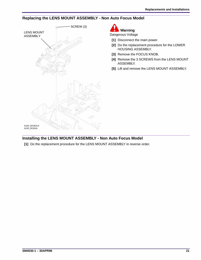
Replacing the LENS MOUNT ASSEMBLY - Non Auto Focus Model
WarningDangerous Voltage
[1] Disconnect the main power.
[2] Do the replacement procedure for the LOWERHOUSING ASSEMBLY.
[3] Remove the FOCUS KNOB.
[4] Remove the 3 SCREWS from the LENS MOUNTASSEMBLY.
[5] Lift and remove the LENS MOUNT ASSEMBLY.
Installing the LENS MOUNT ASSEMBLY - Non Auto Focus Model[1] Do the replacement procedure for the LENS MOUNT ASSEMBLY in reverse order.
A100_0019GA
SCREW (3)
ASSEMBLYLENS MOUNT
A100_0019GCA

SERVICE MANUAL
22 30APR96 – SM4530-1
Replacing the AUTO-FOCUS SWITCH ASSEMBLY
WarningDangerous Voltage
[1] Disconnect the main power.
[2] Do the replacement procedure for the LOWERHOUSING ASSEMBLY.
[3] Remove the FOCUS KNOB.
[4] Remove the short, gray wire from the AUTO-FOCUS DEFEAT SWITCH.
Important
• It is necessary to push the AUTO-FOCUSBRACKET backward and forward to allow accessto the SCREWS on the LENS MOUNTASSEMBLY.
• Keep the AUTO-FOCUS SWITCH LEVER that isconnected to the AUTO FOCUS SWITCH so youcan install it on the new AUTO FOCUS SWITCH.
[5] Remove the 3 SCREWS from the LENS MOUNTASSEMBLY.
[6] Lift and remove the LENS MOUNT ASSEMBLY.
[7] Remove the gray, red, and black wires from theAUTO FOCUS SWITCH ASSEMBLY.
[8] To disconnect and remove the AUTO FOCUSSWITCH, bend the LOCKING TAB on the FOCUSMOTOR BRACKET until it is aligned with the holein the AUTO FOCUS SWITCH.
Installing the AUTO-FOCUS SWITCH ASSEMBLY
ImportantAlign the 2 TABS on the AUTO-FOCUS SWITCH with the FOCUS MOTOR BRACKET, checking that the end of theAUTO-FOCUS LEVER engages with the CYCLE SOLENOID PLUNGER. After the AUTO-FOCUS SWITCH is in thecorrect position, bend the LOCKING TAB to hold the AUTO FOCUS SWITCH in place.
[1] Do the replacement procedure for the AUTO-FOCUS SWITCH in reverse order.
A091_4028GA
wiresand blackgrey, red,
A091_4028GCA
SWITCH LEVER
AUTO FOCUS SWITCH ASSEMBLY
TABLOCKING
AUTO FOCUS
MOTOR BRACKETAUTO FOCUS

Replacements and Installations
SM4530-1 – 30APR96 23
Replacing the FOCUS SHAFT ASSEMBLY - Auto Focus Models
WarningDangerous Voltage
[1] Disconnect the main power.
[2] Do the replacement procedure for the LOWER HOUSING ASSEMBLY.
[3] Remove the FOCUS KNOB.
[4] Remove the short, gray wire from the AUTO-FOCUS DEFEAT SWITCH.
ImportantIt is necessary to push the AUTO-FOCUS BRACKET backward and forward to allow access to the SCREWS on theLENS MOUNT ASSEMBLY.
[5] Remove the 3 SCREWS from the LENS MOUNT ASSEMBLY.
[6] Lift and remove the LENS MOUNT ASSEMBLY.
[7] Remove the FOCUS SHAFT SPRING from the LENS MOUNT BRACKET.
[8] Remote models only: Remove the SPRING from the CLAMP LEVER on the LENS MOUNT BRACKET.
[9] Remove the SPRING from the PHOTOCELL BRACKET.
[10] Remove the E-RING and SPACER from the FOCUS SHAFT ASSEMBLY.
[11] Remove the SCREW from the LENS SUPPORT BRACKET.
[12] Lift and remove the LENS SUPPORT BRACKET.
[13] Remote models: Remove the AUTO-FOCUS SWITCH ASSEMBLY.
[14] Remote models: Remove the SCREW from the RACK SOLENOID ASSEMBLY.
[15] Remote models: Remove the RACK SOLENOID ASSEMBLY and PLUNGER.
[16] Remote models: Remove the SCREW from the FOCUS MOTOR BRACKET ASSEMBLY.
A091_4029HASPRINGBRACKETPHOTOCELL
FOCUS MOTORBRACKET
SPACER
E-RING
ASSEMBLY
AUTO-FOCUSSWITCH
(not shown)RACK LEVER
FOCUS SHAFT
SPRINGCLAMP LEVER
LENS SUPPORT BRACKET
SCREW A091_4029HCA
SOLENOID
PLUNGER
RACK
FOCUS SHAFTSCREWSPRING
SCREW

SERVICE MANUAL
24 30APR96 – SM4530-1
[17] Remove the FOCUS MOTOR BRACKET ASSEMBLY.
[18] Push the RACK LEVER away from the FOCUS SHAFT ASSEMBLY.
[19] Remove the FOCUS SHAFT ASSEMBLY.
Installing the FOCUS SHAFT ASSEMBLY
ImportantDo the adjustments for the PHOTOCELL NULL and AUTO-FOCUS CLAMP after installation. See the Adjustmentssection.
Replacing the FOCUS SHAFT ASSEMBLY - Non Auto-Focus Models
WarningDangerous Voltage
[1] Disconnect the main power.
[2] Do the replacement procedure for the LOWER HOUSING ASSEMBLY.
[3] Remove the FOCUS KNOB.
[4] Remove the 3 SCREWS from the LENS MOUNT ASSEMBLY.
[5] Lift and remove the LENS MOUNT ASSEMBLY.
[6] Remove the FOCUS SHAFT SPRING from the LENS MOUNT BRACKET.
[7] Remove the E-RING and SPACER from the FOCUS SHAFT ASSEMBLY.
[8] Remove the SCREW from the LENS SUPPORT BRACKET.
[9] Lift and remove the LENS SUPPORT BRACKET.
[10] Remove the E-RING and SPACER from the FOCUS SHAFT ASSEMBLY.
[11] Remove the SCREW from the FOCUS MOTOR BRACKET ASSEMBLY.
A091_0020HA
SCREW
E-RING
SPACER
ASSEMBLYFOCUS SHAFT
FOCUS MOTORBRACKET
BRACKETLENS SUPPORT
SCREWA091_0020HCA
FOCUS SHAFTSPRING

Replacements and Installations
SM4530-1 – 30APR96 25
[12] Remove the FOCUS MOTOR BRACKET ASSEMBLY.
[13] Remove the FOCUS SHAFT ASSEMBLY.
Installing the FOCUS SHAFT ASSEMBLY[1] Do the replacement procedure for the FOCUS SHAFT ASSEMBLY in reverse order.
SERVICE MANUAL
26 30APR96 – SM4530-1
Section 2: Adjustments
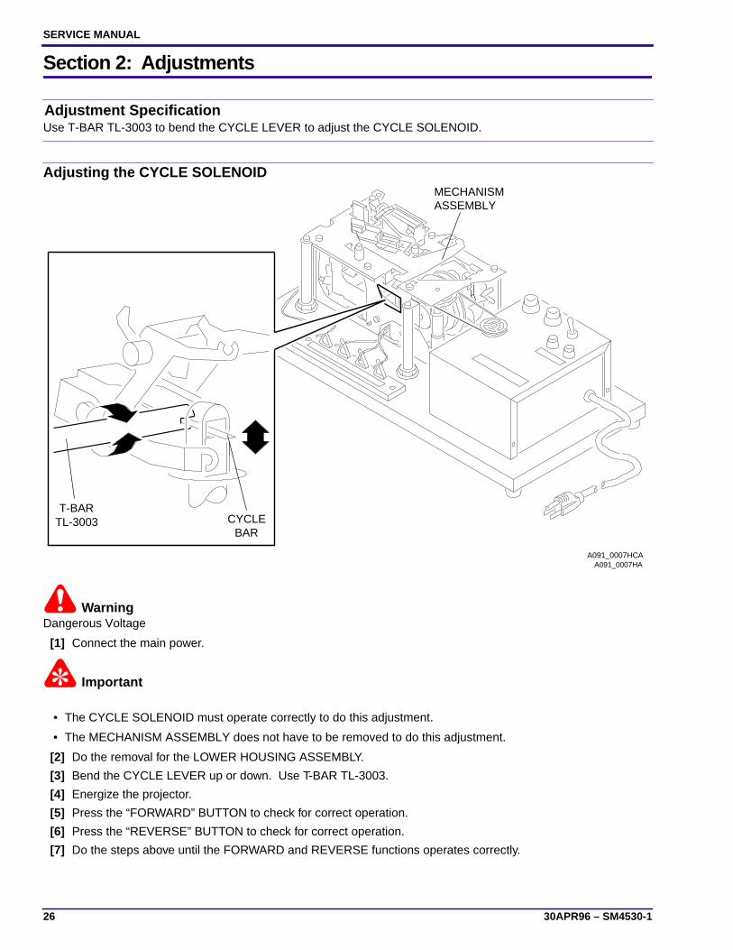
Adjustment SpecificationUse T-BAR TL-3003 to bend the CYCLE LEVER to adjust the CYCLE SOLENOID.
Adjusting the CYCLE SOLENOID
WarningDangerous Voltage
[1] Connect the main power.
Important
• The CYCLE SOLENOID must operate correctly to do this adjustment.
• The MECHANISM ASSEMBLY does not have to be removed to do this adjustment.
[2] Do the removal for the LOWER HOUSING ASSEMBLY.
[3] Bend the CYCLE LEVER up or down. Use T-BAR TL-3003.
[4] Energize the projector.
[5] Press the “FORWARD” BUTTON to check for correct operation.
[6] Press the “REVERSE” BUTTON to check for correct operation.
[7] Do the steps above until the FORWARD and REVERSE functions operates correctly.
A091_0007HA
TL-3003T-BAR
CYCLEBAR
A091_0007HCA
ASSEMBLYMECHANISM

Adjustments
SM4530-1 – 30APR96 27
Adjustment SpecificationThis adjustment adjusts the strobe and timing of the INDEXER LEVER. Use TL-3000. The gate edge of the blackplastic of the INDEXER LEVER should be between the 2 holes at position 2.
Adjusting the INDEXER LEVER ASSEMBLY
WarningDangerous Voltage
[1] Disconnect the main power.
[2] Do the removal for the MECHANISM ASSEMBLY.
[3] Place the MECHANISM ASSEMBLY on the MECHANISM RUNNING FIXTURE TL-3000.
[4] Check the alignment of the INDEXER LEVER with the hole in the TOP PLATE ASSEMBLY at Position 1.
[5] Bend the INDEXER LEVER to the correct position.
[6] Check the travel of the INDEXER LEVER in the FORWARD position. When the INDEXER LEVER moves inthe FORWARD position, the gate edge of the black plastic should be between the 2 holes at Position 2.
[7] Bend the INDEXER LEVER until you reach the correct position.
Adjustment SpecificationUse TL-3000 MECHANISM RUNNING FIXTURE. Use TL-3001 to measure the height of the SLIDE LIFT LEVER.The LEVER should make contact with the low surface of TL-3001. The LEVER should not make contact with thehigh surface of TL-3001.
position 1 position 2
A091_0008HA
MECHANISMRUNNING FIXTURE
MECHANISMASSEMBLY
TOP PLATE
Bendhere.
A091_0008HCA

SERVICE MANUAL
28 30APR96 – SM4530-1
Adjusting the SLIDE LIFT LEVER MANUAL
WarningDangerous Voltage
[1] Disconnect the main power.
ImportantThe older style MECHANISM SLIDE LIFT LEVER has an ECCENTRIC on it to do this adjustment.
[2] Do the removal for the MECHANISM ASSEMBLY.
[3] Place the MECHANISM ASSEMBLY on the MECHANISM RUNNING FIXTURE TL-3000.
[4] Press and hold the SELECT LEVER down to move the SLIDE LIFT LEVER to the highest position.
[5] Measure the height of the SLIDE LIFT LEVER. Use SLIDE LIFT LEVER GAUGE TL-3001. The SLIDE LIFTLEVER should make contact with the low surface of the SLIDE LIFT LEVER GAUGE TL-3001; the SLIDE LIFTLEVER should not make contact with the high surface of the SLIDE LIFT LEVERGAUGE TL-3001.
[6] Bend the SLIDE LIFT LEVER until the adjustment is correct.
Adjustment SpecificationUse TL-3000 MECHANISM RUNNING FIXTURE. Use TL-3001 to measure the height of the SLIDE LIFT LEVER.The LEVER should make contact with the low surface of TL-3001. The LEVER should not make contact with thehigh surface of TL-3001.
A091_0016BA
TL-3001LEVER GUAGESLIDE LIFT
SELECT
A091_0016BCA
(not shown)LEVER
SLIDE LIFTLEVER

Adjustments
SM4530-1 – 30APR96 29
Adjusting the SLIDE LIFT LEVER POWER
WarningDangerous Voltage
[1] Disconnect the main power.
ImportantThe older style MECHANISM SLIDE LIFT LEVER has an ECCENTRIC on it to do this adjustment.
[2] Do the removal for the MECHANISM ASSEMBLY.
[3] Place the MECHANISM ASSEMBLY on the MECHANISM RUNNING FIXTURE TL-3000.
[4] Energize the MECHANISM FIXTURE.
[5] Press and hold the SELECT LEVER down to move the SLIDE LIFT LEVER to the highest position.
[6] Measure the height of the SLIDE LIFT LEVER. Use SLIDE LIFT LEVER GAUGE TL-3001. The SLIDE LIFTLEVER should make contact with the low surface of the SLIDE LIFT LEVER GAUGE TL-3001;the SLIDE LIFT LEVER should not make contact with the high surface of the SLIDE LIFT LEVER GAUGE TL-3001.
[7] Bend the SLIDE LIFT LEVER until the adjustment is correct.
Adjustment SpecificationMake a 5/16 in WRENCH to do this adjustment (see the Tools section). Connect a DIGITAL VOLT METERbetweens PINS 1 and 3 (ZERO POSITION SWITCH). The DVM should measure • without a TRAY and 0 W with aTRAY installed.
A091_0016BA
TL-3001LEVER GUAGESLIDE LIFT
SELECT
A091_0016BCA
(not shown)LEVER
SLIDE LIFTLEVER
SERVICE MANUAL
30 30APR96 – SM4530-1
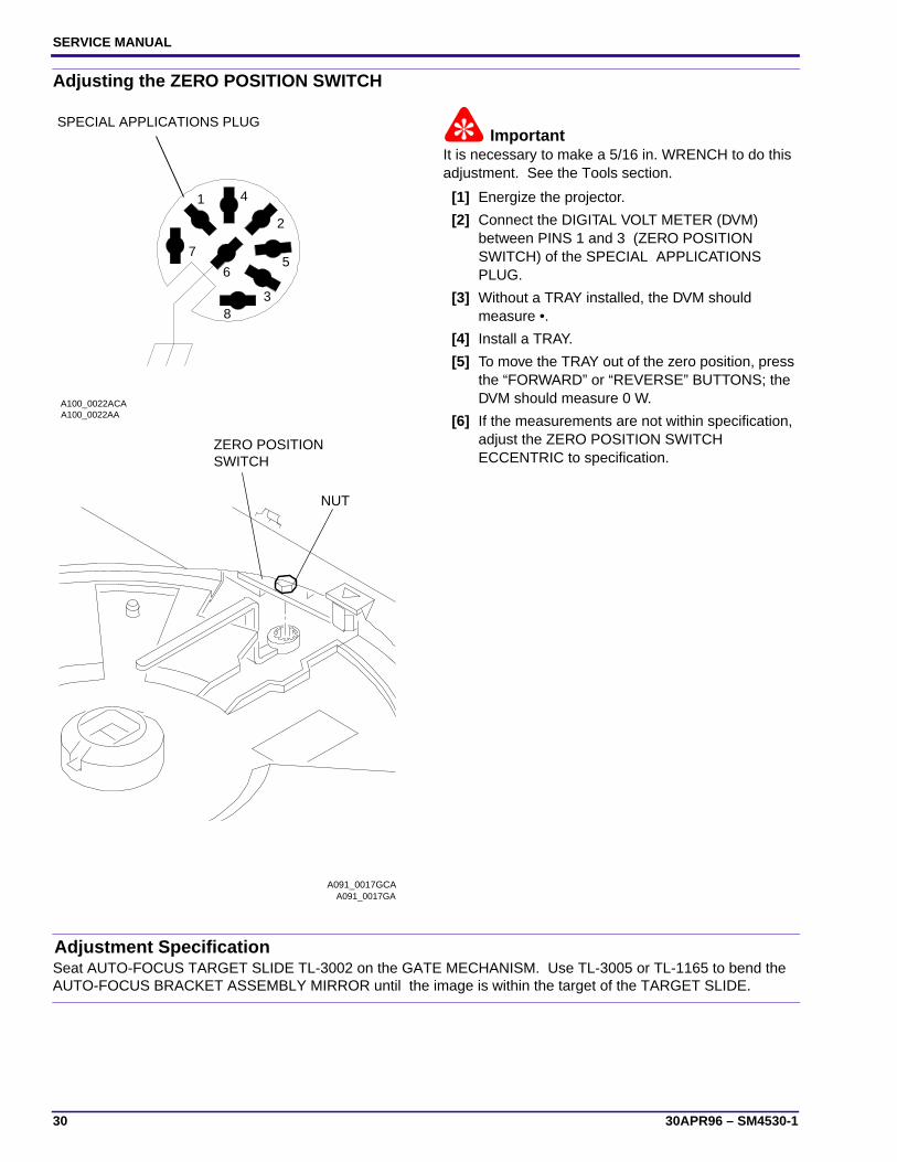
Adjusting the ZERO POSITION SWITCH
ImportantIt is necessary to make a 5/16 in. WRENCH to do thisadjustment. See the Tools section.
[1] Energize the projector.
[2] Connect the DIGITAL VOLT METER (DVM)between PINS 1 and 3 (ZERO POSITIONSWITCH) of the SPECIAL APPLICATIONSPLUG.
[3] Without a TRAY installed, the DVM shouldmeasure •.
[4] Install a TRAY.
[5] To move the TRAY out of the zero position, pressthe “FORWARD” or “REVERSE” BUTTONS; theDVM should measure 0 W.
[6] If the measurements are not within specification,adjust the ZERO POSITION SWITCHECCENTRIC to specification.
Adjustment SpecificationSeat AUTO-FOCUS TARGET SLIDE TL-3002 on the GATE MECHANISM. Use TL-3005 or TL-1165 to bend theAUTO-FOCUS BRACKET ASSEMBLY MIRROR until the image is within the target of the TARGET SLIDE.
1
2
3
4
56
7
8
A100_0022AA
SPECIAL APPLICATIONS PLUG
A100_0022ACA
A091_0017GA
NUT
A091_0017GCA
SWITCHZERO POSITION

Adjustments
SM4530-1 – 30APR96 31
Adjusting the Focus Light Path - Auto Focus Models
WarningDangerous Voltage
[1] Disconnect the main power.
[2] Remove the PROJECTION LENS.
[3] Do the removal for the LOWER HOUSING ASSEMBLY.
ImportantIt is necessary to make a FAN COVER TOOL. See the Tools section.
[4] Install the FAN COVER TOOL over the FAN area and the LAMP MODULE.
[5] Energize the projector.
[6] Set the projector to the LOW LAMP position.
[7] Install the AUTO-FOCUS TARGET SLIDE TL-3002 until it is fully seated in the GATE MECHANISM.
[8] Look through the PROJECTION LENS hole and observe the focus light path on the AUTO-FOCUS TARGETSLIDE TL-3002.
[9] Check the position of the image on the AUTO-FOCUS TARGET SLIDE TL-3002.
[10] Bend the AUTO-FOCUS BRACKET ASSEMBLY MIRROR until the image is within the target on the TARGETSLIDE. Use ADJUSTMENT TOOL TL-3005 or the SPRING HOOK TL-1165.
Adjustment SpecificationUse TL-3002 to observe the focus light path and check the light image. Use T-BAR TL-3003 to bend thePHOTOCELL BRACKET to move the NULL in the center if necessary.
A091_4026HAAUTO-FOCUS TARGET SLIDE TL-3002
light path
image
SPRING HOOK TL-1165
ADJUSTMENT TOOL
ASSEMBLYBRACKETAUTO FOCUS
TL-3005 or
A091_4026HCA

SERVICE MANUAL
32 30APR96 – SM4530-1
Adjusting the NULL
WarningDangerous Voltage
[1] Disconnect the main power.
[2] Do the removal for the LOWER HOUSING ASSEMBLY.
Important
• It is necessary to make a FAN COVER TOOL. See the Tools section.
• If you cannot obtain the NULL position after doing the adjustment approximately 3 times, go to the adjustmentprocedure for the PHOTOCELL.
[3] Install the FAN COVER TOOL over the FAN area and the LAMP MODULE. See the Tools section.
[4] Energize the projector.
[5] Set the projector to the LO-LAMP position.
[6] Install and hold the AUTO FOCUS TARGET SLIDE TL-3002 until it is fully seated in the GATE MECHANISM.
[7] Look through the PROJECTION LENS hole and observe the focus light path on the AUTO-FOCUS TARGETSLIDE TL-3002. Check that the light image is correct. If not, do the Adjusting the FOCUS LIGHT PATH.
[8] Check that the TAB on the CLAMP PAD ASSEMBLY is in the NULL position. If the TAB is not in the correctposition, do the adjustment procedure for the NULL.
[9] Bend the PHOTOCELL BRACKET to move the NULL in the center; use T-BAR TL-3003.
Adjustment SpecificationUse TL-3002 and FAN CAP 232729 to check the adjustment of the PHOTOCELL.
A091_4031BA TL-3002TARGET SLIDEAUTO-FOCUS
A091_4031BCA
LENSPROJECTION
light path
NULL position
PADCLAMP LEVER
TAB
T-BARTL-3003

Adjustments
SM4530-1 – 30APR96 33
Adjusting the PHOTOCELL
WarningDangerous Voltage
[1] Disconnect the main power.
[2] Do the removal for the LOWER HOUSINGASSEMBLY.
ImportantIt is necessary to make a FAN COVER TOOL. See theTools section.
[3] Install the FAN COVER TOOL over the FAN areaand the LAMP MODULE. See the Tools section.
[4] Energize the projector.
[5] Set the projector to the LO-LAMP position.
[6] Install and hold the AUTO FOCUS TARGETSLIDE TL-3002 until it is fully seated in the GATEMECHANISM.
[7] Look through the PROJECTION LENS hole andobserve the focus light path on the AUTO-FOCUSTARGET SLIDE TL-3002. Check that the lightpath is correct. If not, do the adjustmentprocedure for the FOCUS LIGHT PATH.
[8] Disconnect the main power.
[9] Heat the 2 POSTS on the PHOTOCELLHOUSING to allow the POSTS to bend enough topull the PHOTOCELL CIRCUIT BOARD up andoff the PHOTOCELL HOUSING. Use aSOLDERING IRON.
[10] Remove the 2 Wratten FILTERS and thePHOTOCELL MASK.
[11] Install the FAN CAP 232729 in the PHOTOCELLHOUSING.
A091_4032GA
CIRCUIT BOARDPHOTOCELL
PHOTOCELLHOUSING
POST (2)
A091_4032GCA
PHOTOCELLMASK
FILTER (2)wratten
A091_4033GA
light image
hole FAN CAP
A091_4033GCA
FAN CAP

SERVICE MANUAL
34 30APR96 – SM4530-1
[12] Manually move the CLAMP PAD ASSEMBLY until the TAB is in the NULL position.
WarningDangerous Voltage
[13] Connect the main power.
ImportantIt is necessary to make a FAN COVER TOOL. See the Tools section.
[14] Install the FAN COVER TOOL over the FAN area and the LAMP MODULE. See the Tools section.
[15] Install and hold the AUTO FOCUS TARGET SLIDE TL-3002 until it is fully seated in the GATE MECHANISM.
[16] Set the projector to the LO-LAMP position.
[17] Observe the image of the focus light path on the bottom of the FAN CAP; the light path should be in the centerof the hole in the FAN CAP.
[18] Bend the CLAMP PAD ASSEMBLY until the image is in the center of the hole in the FAN CAP.
[19] Assemble the PHOTOCELL MASK, FILTERS and PHOTOCELL BOARD.
A091_4027BAA091_4027BCA
light path
PADCLAMP LEVER
TAB
NULL position
A091_4030BA
AUTO-FOCUSTARGET SLIDETL-3002
T-BAR TL-3003
light imageFAN CAP
CLAMP PAD ASSEMBLY
A091_4030BCA
hole

Adjustments
SM4530-1 – 30APR96 35
Adjustment SpecificationUse TL-1744 to check that the CLAMP PAD ASSEMBLY moves forward and backward.
Adjusting the CLAMP PAD ASSEMBLY
WarningDangerous Voltage
[1] Disconnect the main power.
Important
• If the CLAMP ASSEMBLY has a COIL SPRING onthe ADJUSTMENT SCREW, remove it. This willmake the adjustment easier.
• It is necessary to make a FAN COVER TOOL. Seethe Tools section.
[2] Do the removal for the LOWER HOUSINGASSEMBLY.
[3] Install the FAN COVER TOOL over the FAN areaand the LAMP MODULE. See the Tools section.
[4] Connect the REMOTE CONTROL ASSEMBLYEC-3 to the REMOTE RECEPTACLE.
[5] Connect the main power.
[6] Loosen the NUT on the CLAMP PAD ASSEMBLY.
[7] Energize the REMOTE FOCUS in either direction.
[8] Rotate the SCREW on the CLAMP PADASSEMBLY to adjust the pressure of theREMOTE FOCUS CLAMP on the CLAMP PADASSEMBLY until the CLAMP PAD ASSEMBLYdoes not move.
[9] Release the REMOTE FOCUS.
[10] Tighten the NUT on the CLAMP PAD ASSEMBLY.
[11] Install the AUTO-FOCUS GAUGE TL-1744 in theMECHANISM GATE. The CLAMP PADASSEMBLY should move forward and backwardusing TL-1744. If not, adjust the SCREW on theCLAMP PAD ASSEMBLY again; the CLAMP PADASSEMBLY adjustment is too tight and notcorrect.
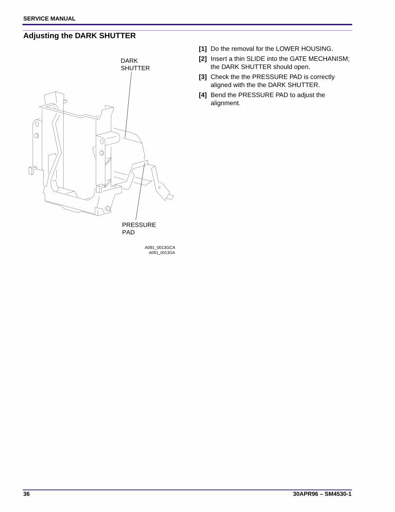
Adjustment SpecificationThe PRESSURE PAD should be aligned with the DARK SHUTTER.
A091_4041GAA091_4041GCA
SCREW
NUT
CLAMP PADASSEMBLY
SERVICE MANUAL
36 30APR96 – SM4530-1
Adjusting the DARK SHUTTER
[1] Do the removal for the LOWER HOUSING.
[2] Insert a thin SLIDE into the GATE MECHANISM;the DARK SHUTTER should open.
[3] Check the the PRESSURE PAD is correctlyaligned with the the DARK SHUTTER.
[4] Bend the PRESSURE PAD to adjust thealignment.
A091_0013GA
SHUTTERDARK
PADPRESSURE
A091_0013GCA

Lubrication
SM4530-1 – 30APR96 37
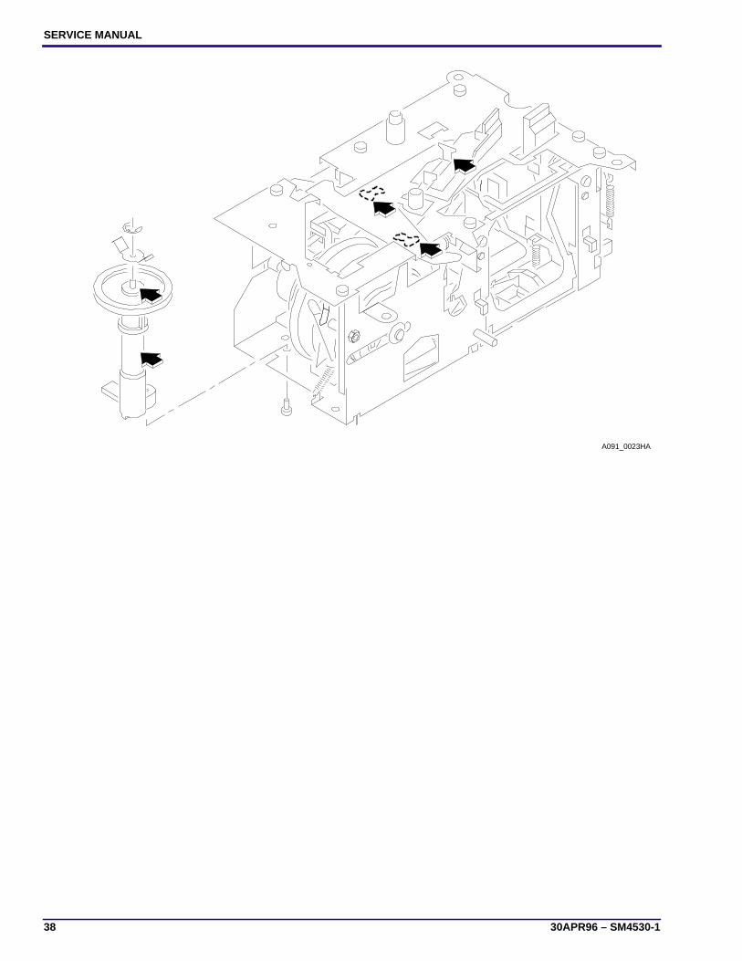
Section 3: Lubrication
[1] Apply lubricant SUPER LUBE TL-4276 to the following parts and areas of the projector; see the illustrations:
• FAN
• INDEXER LEVER and TOP PLATE
• WORM PULLEY ASSEMBLY
• CAM STACK ASSEMBLY
• CYCLE LEVERS
• PIVOT SHAFT and LEVERS
• LENS MOUNT ASSEMBLY
A091_4037GA A100_0020GA
SERVICE MANUAL
38 30APR96 – SM4530-1
A091_0023HA

Lubrication
SM4530-1 – 30APR96 39
A091_0022DA

SERVICE MANUAL
40 30APR96 – SM4530-1
Section 4: Tools
The LOWER HOUSING ASSEMBLY is a part of the cooling function. To operate the projector with the LOWERHOUSING removed, make a FAN COVER TOOL.
Tool No. Description
TL-1744 AUTO-FOCUS GAUGE
TL-2264 FOCUS TEST (flat field)
TL-3000 MECHANISM RUNNING FIXTURE (optional)
TL-3002 AUTO-FOCUS TARGET SLIDE
TL-3003 ADJUSTMENT T-BAR
TL-3005 ADJUSTMENT TOOL
TL-3255 Torx DRIVER SET
TL-4276 SUPER LUBE
DIGITAL MULTIMETER
11.5 cm(4.5 in.)
A091_0024GA
TOOL
A091_0024GCA
COVERFAN
Cut here.

Specifications
SM4530-1 – 30APR96 41
Section 5: Specifications
Item Description
Electrical Supply Standard U.S. Models: 110 - 125 V acJapan J Models: 100 V AC, 60 Hz onlyKorea KK Models: 220 V AC, 60 Hz only
Power Consumption 400 W
Dimensions • Height: 119 mm (4.69 in.) without TRAY
• Width: 238 mm (12.93 in.)
• Length: 295 mm (11.6 in.)
Slide size 35 mm, 50 x 50 mm (2 x 2 in.)
Slide change time 1 second
Lamp(in LO position)
• EXR 82 V, 300 W, 35 hours average life
• EXW 82 V, 300 W, 15 hours average lamp life
• FHS 82 V, 300 W, 70 hours average life
• EXY 82 V, 300 W, 200 hours average life
Lumen Output • 900 minimum with EXR lamp
• Lowest corner to center ratio is 55% minimum
• Test method:
– Ektagraphic
– 102 mm, F/2.8 LENS aperture (24 x 36 mm), compatiblewith European specification DIN 19027
Operating temperature • 4.5 C (40 F), 15% humidity in low
• 49 C (120 F), 15% humidity in high
• 21 - 27 C (70 - 80 F), 20 - 60% humidity optimum
Cooling Fan speed is 2780 or 3000 RPMs, 1360 BTUs per hour to coolprojector
Approvals UL
Environmental storage Complies with storage test specifications (TS 172)
Environmental operation Complies with climactic test specifications (TS 218)
Safety • 3 GROUNDED POWER CORDS, detachable
• Heat sensitive interrupt fuses
• 109 C power to motor (lamp fuse)
• 171 C MOTOR
Dielectric strength Apply 1200 V AC, 60 Hz for 1 second; maximum leakagecurrent is 2.5 mA.
Automatic Timer Operates between the following times:• Fast = 3 1 second
• Slow = 22 6 seconds
Elevation 14 maximum front elevation assembly.

SERVICE MANUAL
42 30APR96 – SM4530-1
Auto Focus System • After the initial focus adjustment, the auto-focus system willadjust for the difference in the slide position from slide toslide. This focus adjustment will occur within 1 second afterthe slide is inserted into the GATE.
• The focus adjustment variation should not change from thefocus and reverse specifications by more than 3 times thefocus and reverse specifications.
Reliability The projector can operate for 2000 hours or 2,000,000 cycles.The projector has a MTBF (mean time between failures) of 7500operation hours.
Maintenance Preventive maintenance by a qualified service person isrecommended every 1500 hours of operation, or after 1 year.
Warranty See the owner’s manual.
7-PIN REMOTE CONTROL(See illustration below.)
• PIN 1 - Black, REMOTE FOCUS
• PIN 2 - Green, FORWARD TRAY CYCLE
• PIN 3 - Orange, REVERSE TRAY CYCLE
• PIN 4 - Brown, RACK SOLENOID
• PIN 5 - Yellow, COMMON
• PIN 6 - Brown, LAMP CONTROL
• PIN 6 - White, LAMP CONTROL
9-PIN SPECIAL APPLICATIONS(See illustration below.)
• PINS 1 and 3 - ZERO POSITION SWITCH
• PINS 4 and 5 - SHUTTER SWITCH
• PINS 7 and 8 - LOW VOLTAGE SUPPLY, 25.5 V AC, 500mA, 1/2 Amp Maximum
• PINS 6 and 8 - FORWARD TRAY CYCLE
• PINS 2 and 8 - REVERSE TRAY CYCLE and SHELL PLUGGROUND
Item Description
1
23
4
5
6
7
A100_0023AA
Y
W
N
OG
NK
7-PIN PLUG
A100_0023ACA
24 V AC 24 V AC
24 V AC0 V ACCommon
Unloaded82 V AC
1
2
3
4
56
7
8
A100_0022AA
SPECIAL APPLICATIONS PLUG
A100_0022ACA

Diagnostics
SM4530-1 – 30APR96 43
Section 6: Diagnostics
MAIN MOTOR Voltages
MAIN MOTOR PIN Colors
MAIN MOTOR PIN Voltages
PIN Color
12 brown
11 red
10 violet
9 yellow
8 blue
7 not used
PIN Voltage
8-9 25.5 V ac
10-11 14.5 V ac
11-12 14.5 V ac
10-12 29 V ac
12
11
10
9
8
7
A091_0006BA
brown
white
black
84.2 V1.6
117 V AC6.1
LAMP VOLTAGE is74 V ACbetween brownand white forLONG LIFE MODELS
MOTOR
A091_0006BCA

SERVICE MANUAL
44 30APR96 – SM4530-1
9-PIN SPECIAL APPLICATION PLUG
9-PIN SPECIAL APPLICATION PLUG
PHOTOCELL Voltages
PHOTOCELL Voltages
PINS Description
1 and 3 ZERO POSITION SWITCH
4 and 5 SHUTTER SWITCH
7 and 8 LOWER VOLTAGE SUPPLY, 2.5 V AC, 500 mA, 1/2 Amp maximum
6 and 8 FORWARD TRAY CYCLE
2 and 8 REVERSE TRAY CYCLE and SHELL GROUND
PINS Voltage
1-2 14.5 V ac
2-3 14.5 V ac
1-3 29 V ac
1
2
3
4
56
7
8
A100_0022AA
SPECIAL APPLICATIONS PLUG
A100_0022ACA
1 2
3
A091_4036AAA091_4036ACA
PHOTOCELL

Diagnostics
SM4530-1 – 30APR96 45
5-PIN REMOTE CORD PLUG Voltages
5-PIN REMOTE PLUG Voltages
PIN Description
white Reverse
red Forward
yellow Common
brown RACK SOLENOID
black Focus - REMOTE
A100_0001BC_
YELLOWYELLOW
FOCUS
BRN
REV
WHITE
BLACK
RED
FWD
KODAK EC-3 REMOTE CONTROL

SERVICE MANUAL
46 30APR96 – SM4530-1
SMALL COMPONENT BOARD ASSEMBLY 256809 Voltages
Description Component RED +, BLACK - Voltage
TIMER Circuit CR3 + to - 32 V DC
TIMER Circuit Q3 - G to + A 32 V DC
TIMER Circuit Q4 - G to + K 18.1 V DC
CYCLE HOLD DOWNREVERSE
CR4 + to - 18.0 V DC
FOCUS CR2 + to - 28.0 V DC
FOCUS RACK USEREMOTE
CR5 + to - 18.0 V DC
FOCUS Q1 - B to + C 23.3 V DC
FOCUS Q2 - G to + A 28.0 V DC
W BWK R A V V O B YWWRNGYR
CR5
F1
R7
CR4
C5
CR3
CR2
Q1
Q2
R3
R4
R6
R5
CR1C1
R17
C4
C3 C2
R12R11R10
R13R14
R15CR6
Q3
+ +
Q4
SLIDE PROJECTOR BOARD
J1J2
A091_4034DC
Diagnostics
SM4530-1 – 30APR96 47
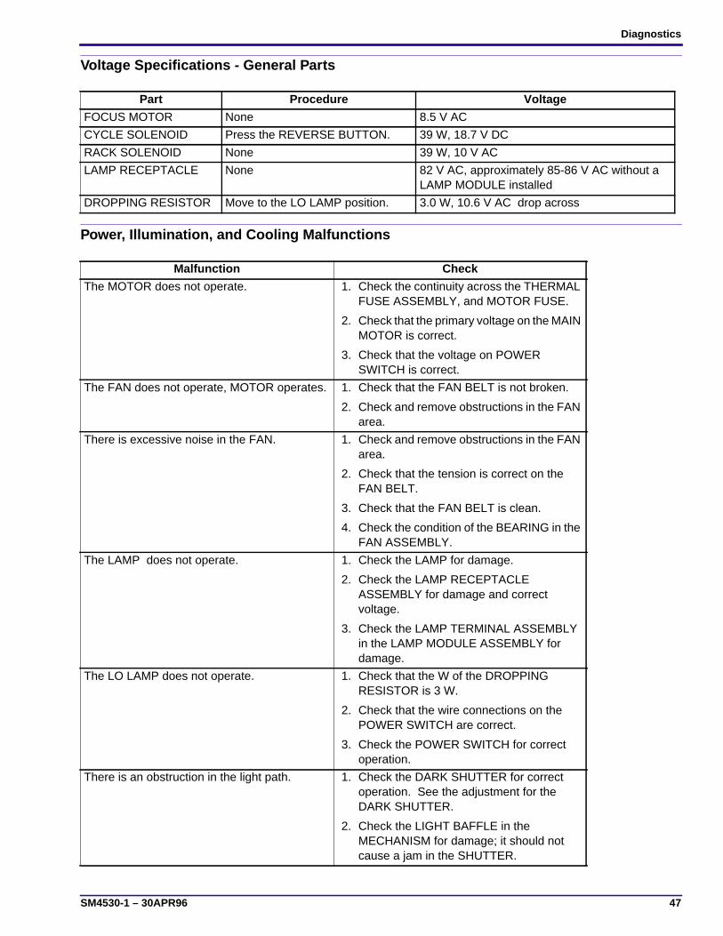
Voltage Specifications - General Parts
Power, Illumination, and Cooling Malfunctions
Part Procedure Voltage
FOCUS MOTOR None 8.5 V AC
CYCLE SOLENOID Press the REVERSE BUTTON. 39 W, 18.7 V DC
RACK SOLENOID None 39 W, 10 V AC
LAMP RECEPTACLE None 82 V AC, approximately 85-86 V AC without aLAMP MODULE installed
DROPPING RESISTOR Move to the LO LAMP position. 3.0 W, 10.6 V AC drop across
Malfunction Check
The MOTOR does not operate. 1. Check the continuity across the THERMALFUSE ASSEMBLY, and MOTOR FUSE.
2. Check that the primary voltage on the MAINMOTOR is correct.
3. Check that the voltage on POWERSWITCH is correct.
The FAN does not operate, MOTOR operates. 1. Check that the FAN BELT is not broken.
2. Check and remove obstructions in the FANarea.
There is excessive noise in the FAN. 1. Check and remove obstructions in the FANarea.
2. Check that the tension is correct on theFAN BELT.
3. Check that the FAN BELT is clean.
4. Check the condition of the BEARING in theFAN ASSEMBLY.
The LAMP does not operate. 1. Check the LAMP for damage.
2. Check the LAMP RECEPTACLEASSEMBLY for damage and correctvoltage.
3. Check the LAMP TERMINAL ASSEMBLYin the LAMP MODULE ASSEMBLY fordamage.
The LO LAMP does not operate. 1. Check that the W of the DROPPINGRESISTOR is 3 W.
2. Check that the wire connections on thePOWER SWITCH are correct.
3. Check the POWER SWITCH for correctoperation.
There is an obstruction in the light path. 1. Check the DARK SHUTTER for correctoperation. See the adjustment for theDARK SHUTTER.
2. Check the LIGHT BAFFLE in theMECHANISM for damage; it should notcause a jam in the SHUTTER.

SERVICE MANUAL
48 30APR96 – SM4530-1
Slide Transport Malfunctions
Malfunction Check
Forward and reverse do not operate using theFRONT PANEL BUTTONS or REMOTECONTROL.
1. Check that the secondary voltage on theMAIN MOTOR is correct.
2. Check that the W across the CYCLESOLENOID COIL are correct.
3. Check that the voltage across the CYCLESOLENOID is correct.
Forward does not operate, reverse operates,voltages are correct.
1. Check that the CYCLE LEVER andRATCHET PLATE are clean. Clean andlubricate the parts as necessary. UseSUPER LUBE TL-4276.
2. Install a new CAM STACK ASSEMBLY; themalfunction is within the CAM.
Reverse does not operate, forward operates,voltages are correct.
1. Do the adjustment for the CYCLESOLENOID.
2. Check that the DIRECTION LEVERSPRING is on the DIRECTION LEVER.
3. Check the DIRECTION LEVER for binds.Excessive lubrication and dirt can causebinds.
Projector does not complete a cycle; FANoperates.
1. Check for a broken MECHANISM DRIVEBELT.
2. Check the CYCLE LEVER and RATCHETLEVER on the CAM SHAFT ASSEMBLY forthe following:
• correct alignment of the CYCLE LEVER
• damage to parts
• lubrication of the CYCLE LEVER (useSUPER LUBE TL-4276)
3. Check the CYCLE SOLENOID for correctoperation. See the Voltage chart.
Projector has continual cycle. 1. Check the CYCLE LEVER for correctalignment. See the adjustment for theCYCLE LEVER.
2. Check for damage to parts.
3. Check for a short•circuit in the wires:
• Use a tool to hold the CYCLE LEVERdown on the RATCHET LEVER. Ifthere is a short•circuit causing themalfunction, the SOLENOID will beenergized. If there is a bind, the CAMwill not rotate.
4. Check that the CAM SHAFT ASSEMBLYRATCHET SPRING is installed correctly.
5. If there is a bind in the CAM STACK, installa new CAM.

Diagnostics
SM4530-1 – 30APR96 49
The projector does not change cycles whenusing a DISSOLVE CONTROL; the REMOTECONTROL and CONTROL PANEl BUTTONSoperate correctly.
1. If the CYCLE LEVER and the RATCHETPLATE are dirty.
• Clean and apply lubricant SUPERLUBE TL-4276 to thE CYCLE LEVERand RATCHET PLATE.
• If this does not correct the malfunction,install a new CAM SHAFT ASSEMBLY.
SLIDE TRAY does not advance smoothly. 1. Check the SLIDE TRAY LATCH for correctalignment.
2. Operate the projector in the forwarddirection.
• Check that the INDEXER LEVERASSEMBLY is in the correct alignmentwith the holes at positions A and B.
• Do the adjustment for the INDEXERLEVER ASSEMBLY.
• Check the condition of the LOCATORLEVER, it should not be bent.
• Check the height of the SLIDE LIFTLEVER; the lower corner of the LIFTLEVER RAMP is parallel with the TOPHOUSING. If the height is not correct,do the adjustment for the MANUAL andPOWER SLIDE LIFT LEVERECCENTRICS.
SLIDE TRAY advances when “REVERSE” ispressed.
1. Do the adjustment for the CYCLESOLENOID.
2. Check that the SPRING is on theDIRECTION LEVER.
3. Check for a bind in the DIRECTION LEVERASSEMBLY.
4. Check that the DIRECTION LEVER LINK isin the correct position.
SLIDE TRAY does not rotate freely when theSELECT BUTTON is pressed down. Theprojector has power.
1. Press and release the SELECT BUTTON.
• Check that the LOCATOR LEVERmoves correctly and is not bent.
2. Press and hold the SELECT BUTTONdown.
• Check the SLIDE LIFT LEVER RAMPfor damage.
3. Check the height of the SLIDE LIFTLEVER; the lower corner of the LIFTLEVER RAMP is parallel with the TOPHOUSING. If the height is not correct, dothe adjustment for the MANUAL andPOWER SLIDE LIFT LEVERECCENTRICS.
Malfunction Check
SERVICE MANUAL
50 30APR96 – SM4530-1
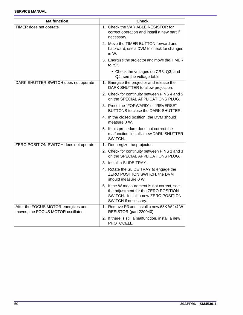
TIMER does not operate 1. Check the VARIABLE RESISTOR forcorrect operation and install a new part ifnecessary.
2. Move the TIMER BUTTON forward andbackward; use a DVM to check for changesin W.
3. Energize the projector and move the TIMERto “S”.
• Check the voltages on CR3, Q3, andQ4, see the voltage table.
DARK SHUTTER SWITCH does not operate 1. Energize the projector and release theDARK SHUTTER to allow projection.
2. Check for continuity between PINS 4 and 5on the SPECIAL APPLICATIONS PLUG.
3. Press the “FORWARD” or “REVERSE”BUTTONS to close the DARK SHUTTER.
4. In the closed position, the DVM shouldmeasure 0 W.
5. If this procedure does not correct themalfunction, install a new DARK SHUTTERSWITCH.
ZERO POSITION SWITCH does not operate 1. Deenergize the projector.
2. Check for continuity between PINS 1 and 3on the SPECIAL APPLICATIONS PLUG.
3. Install a SLIDE TRAY.
4. Rotate the SLIDE TRAY to engage theZERO POSITION SWITCH, the DVMshould measure 0 W.
5. If the W measurement is not correct, seethe adjustment for the ZERO POSITIONSWITCH. Install a new ZERO POSITIONSWITCH if necessary.
After the FOCUS MOTOR energizes andmoves, the FOCUS MOTOR oscillates.
1. Remove R3 and install a new 68K W 1/4 WRESISTOR (part 220040).
2. If there is still a malfunction, install a newPHOTOCELL.
Malfunction Check

Diagnostics
SM4530-1 – 30APR96 51
Focus Malfunctions
Malfunction Check
No manual focus 1. Check the FOCUS SHAFT SPRING for thecorrect tension.
2. Check the LENS SUPPORT SPRING forcorrect tension.
3. Check the LENS DRIVE GEAR on theFOCUS SHAFT ASSEMBLY for damageand install a new part if necessary.
No remote focus (Non Auto Focus models) 1. Check the REMOTE CORD for damage;use a REMOTE CORD that has nodamage.
2. Actuate and hold the REMOTE CONTROL.
3. Check that the voltage across the FOCUSMOTOR is 8.5 V AC. If the voltage iscorrect, install a new FOCUS MOTOR.
Check that the secondary voltage on the MAINMOTOR is correct.
No remote focus, RACK SOLENOIDASSEMBLY operates (Auto Focus Models)
1. Check that the REMOTE CORD operatescorrectly; use a REMOTE CORD you knowis good (EC 3).
2. Actuate and hold the REMOTE CONTROL.
3. Check that the voltage across the FOCUSMOTOR is 8.5 V AC. If the voltage iscorrect, install a new FOCUS MOTOR.
4. Check the AUTO FOCUS SWITCHASSEMBLY for correct operation.
5. Check the secondary voltages on the MAINMOTOR.

SERVICE MANUAL
52 30APR96 – SM4530-1
No auto-focus 1. Check that the AUTO-FOCUS DEFEATSWITCH is in the “ON” position.
2. Check that the MAIN PROJECTION LAMPoperates correctly.
3. Insert the TARGET SLIDE TL-3002 in theGATE MECHANISM.
• Check that the TARGET is correctlyaligned. If not, see the Adjustmentsection.
4. Check that the voltages across thePHOTOCELL are correct. The voltage from1 to 2 is 14.5 V ac. The voltage from 2 to 3is 14.5 V ac. The voltage from 1 to 3 is 29V ac.
5. Make a short• between 1 and 2; the FOCUSMOTOR should rotate.
6. Make a short•circuit between 2 and 3; theFOCUS MOTOR should rotate in thereverse direction.
7. If the FOCUS MOTOR operates correctly,install a new PHOTOCELL. If the FOCUSMOTOR does not operate correctly,measure the voltages on the CIRCUITBOARD.
Slow auto-focus movement 1. Check that the alignment of the FOCUSLIGHT PATH and NULL is correct.
2. Check the resolution of the FOCUS LIGHTPATH. Clean the AUTO FOCUS MIRRORand BRACKET ASSEMBLY.
3. Install a new PROJECTION LAMP ifnecessary.
4. Install a new PHOTOCELL.
5. Check the components on the CIRCUITBOARD for damage.
Malfunction Check

Diagnostics
SM4530-1 – 30APR96 53
AUTO FOCUS MOTOR operates continually 1. Install the TARGET SLIDE TL-3002 in theGATE MECHANISM.
2. Check that the alignment of the TARGETand NULL is correct. If not, see theAdjustments section.
3. Check for a light leak:
• Install a different LAMP MODULEASSEMBLY. If the FOCUS MOTORstops operating continually, install anew LAMP MODULE ASSEMBLY.
4. Check that the voltages across thePHOTOCELL are correct. The voltage from1 to 2 is 14.5 V ac. The voltage from 2 to 3is 14.5 V ac. The voltage from 1 to 3 is 29V ac.
5. Check that the PHOTOCELL HOUSINGhas 2 FILTERS.
6. Install a new PHOTOCELL.
7. Check the components on the CIRCUITBOARD for damage.
AUTO FOCUS MOTOR operates continually inforward only or reverse only and does notoperate (stops) in the null position.
1. Check that the wires of the AUTO FOCUSMOTOR are in the correct position; the bluewire goes to the mark on the AUTO FOCUSMOTOR.
AUTO FOCUS adjusts after REMOTE use 1. Do the adjustment for the CLAMP LEVERASSEMBLY.
Malfunction Check

Printed in U.S.A. • sm4530_1.fm
EASTMAN KODAK COMPANYRochester, NY 14650
Kodak, Ektagrphic, and Wratten are tradmarks.