knx tp1 topologyknx.org/media/fileadmin/template/documents/downloads_support_men… · coupler:...
TRANSCRIPT

KNX Association
KNX TP1 Topology
KNX BASIC COURSE
Home and Building Management Systems KNX Association KNX TP1 Topology Topology_E1212a 2/22
Table of Contents 1 Topology – Overall view ............................................................................................ 3 2 Topology ................................................................................................................... 4 3 Topology: Area .......................................................................................................... 5 4 Topology: Several Areas ........................................................................................... 6 5 Physical address ....................................................................................................... 7 6 Coupling Unit: Gate Function .................................................................................... 8 7 Coupler: Block Diagram ............................................................................................ 9 8 Coupling Unit: Types and Functions .........................................................................10 9 Coupling Unit: Fields of Application ..........................................................................10 10 Connecting Several Lines ........................................................................................11 11 Practical Example for explanation of functionality .....................................................12 12 Internal Line Telegram .............................................................................................13 13 Line-crossing Telegram ............................................................................................14 14 Area-crossing Telegram ...........................................................................................15 15 Coupling Unit: Routing Counter ................................................................................16 16 KNX – Internal and External Interfaces ....................................................................17 17 Topology – Structure in building ...............................................................................18 18 Taking into account higher telegram rates: IP Network ............................................20 19 Limits to the use of IP routers ...................................................................................22

KNX BASIC COURSE
Home and Building Management Systems KNX Association KNX TP1 Topology Topology_E1212a 3/22
Figure 1: Maximum topological size of a KNX TP installation
1 Topology – Overall view In the figure above the maximum topological size of a KNX TP installation is shown.

KNX BASIC COURSE
Home and Building Management Systems KNX Association KNX TP1 Topology Topology_E1212a 4/22
Figure 2: Topology - Line
2 Topology Each bus device (DVC) can exchange information with any other device by means of telegrams. One line consists of a maximum of 4 line segments, each with a maximum of 64 bus devices. Each segment requires an appropriate power supply.1 The actual number of devices is dependent on the power supply selected and the power input of the individual devices.
1 This chapter assumes the use of central power supply units only. For distributed power supply
units, consult chapter ‘TP1 installation’.

KNX BASIC COURSE
Home and Building Management Systems KNX Association KNX TP1 Topology Topology_E1212a 5/22
Figure 3: Topology - Area
3 Topology: Area If more than 1 line is to be used or if a different structure is to be selected, then up to 15 lines can be connected to a main line via a line coupler (LC). This is called an area. It is also possible to have up to 64 bus devices on the main line. The maximum number of bus devices on the main line decreases by the number of line couplers in use. Each line, including the main line, must have its own power supply unit. Line repeaters may not be used on backbone or main lines.
KNX BASIC COURSE
Home and Building Management Systems KNX Association KNX TP1 Topology Topology_E1212a 6/22
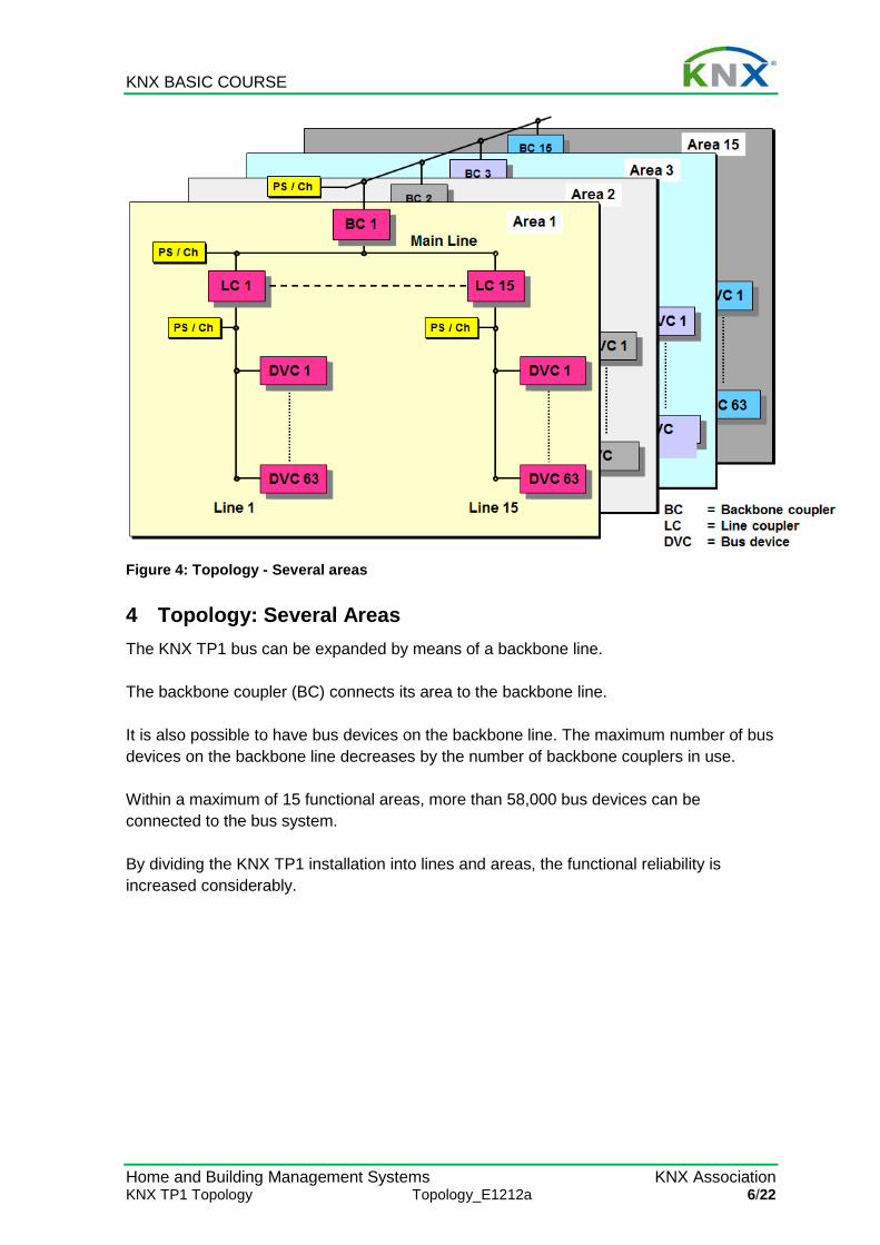
Figure 4: Topology - Several areas
4 Topology: Several Areas The KNX TP1 bus can be expanded by means of a backbone line. The backbone coupler (BC) connects its area to the backbone line. It is also possible to have bus devices on the backbone line. The maximum number of bus devices on the backbone line decreases by the number of backbone couplers in use. Within a maximum of 15 functional areas, more than 58,000 bus devices can be connected to the bus system. By dividing the KNX TP1 installation into lines and areas, the functional reliability is increased considerably.

KNX BASIC COURSE
Home and Building Management Systems KNX Association KNX TP1 Topology Topology_E1212a 7/22
Figure 5: Physical address
5 Physical address The physical address serves to clearly identify the bus device and describes its location within the topology. F = 1-15 addresses the areas 1-15 F = 0 addresses the bus devices on the backbone line L = 1-15 addresses the lines 1-15 in the areas defined by F L = 0 addresses the main line D = 1-255 addresses the bus devices on the line defined by L D = 0 addresses the coupler The address of an unloaded bus coupler is 15.15.255.

KNX BASIC COURSE
Home and Building Management Systems KNX Association KNX TP1 Topology Topology_E1212a 8/22
Figure 6: Coupling unit: Gate function
6 Coupling Unit: Gate Function When the parameters are assigned, the coupling unit is provided with a filter table. All received group telegrams are routed if they are listed in the filter table. In this way, each line works independently. Only line-crossing telegrams are routed. The yellow LEDs of the coupler flicker when a telegram is received on the respective line. The line repeater passes on all telegrams; it has no filter table.

KNX BASIC COURSE
Home and Building Management Systems KNX Association KNX TP1 Topology Topology_E1212a 9/22
Figure 7: Coupler: Block Diagram
7 Coupler: Block Diagram The coupler is designed for DIN rail mounting. The primary line is connected via a bus terminal. The secondary line is connected through the data rail or via a bus terminal. New types of couplers (from July 2003 onwards) can be programmed from both the secondary as well as the primary line. In the old line coupler type (until June 2003), the secondary line supplies the power for both bus coupling units, the logic and the filter table memory. The new coupler has only 1 controller and is supplied by the primary line. This has the advantage, that the coupler can report secondary line power cuts. A lithium battery with a life span of more than 10 years (also without connection to the bus) provides the backup supply for the memory containing the filter table in the old line coupler type. The new type is equipped with a Flash ROM memory, which does not need backup battery power. The coupler electrically isolates the lines from each other as ruled by SELV standard.
KNX BASIC COURSE
Home and Building Management Systems KNX Association KNX TP1 Topology Topology_E1212a 10/22
8 Coupling Unit: Types and Functions The coupling unit can be used as: Backbone coupler BC Connection: Backbone line to Main line Line coupler LC Connection: Main line to Secondary line Line repeater LR For expanding a line by a line segment with up to 64 additional bus devices and an additional cable length of 1,000 m. Bus and line couplers only pass on line-crossing telegrams, whereas a line repeater passes on all telegrams. Backbone coupler, line coupler and line repeater are identical devices. The tasks to be carried out are dependent on the location and the corresponding designated physical address.
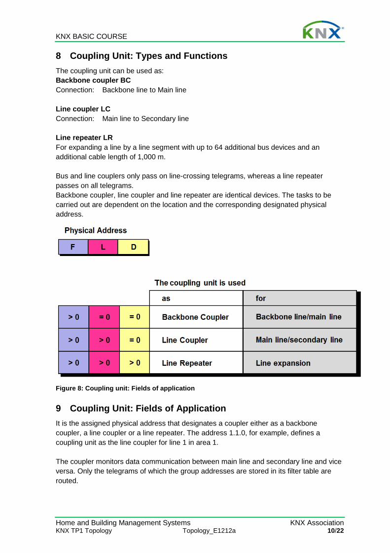
Figure 8: Coupling unit: Fields of application
9 Coupling Unit: Fields of Application It is the assigned physical address that designates a coupler either as a backbone coupler, a line coupler or a line repeater. The address 1.1.0, for example, defines a coupling unit as the line coupler for line 1 in area 1. The coupler monitors data communication between main line and secondary line and vice versa. Only the telegrams of which the group addresses are stored in its filter table are routed.
KNX BASIC COURSE
Home and Building Management Systems KNX Association KNX TP1 Topology Topology_E1212a 11/22
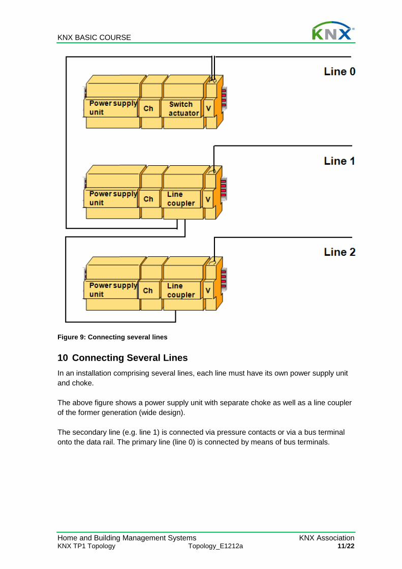
Figure 9: Connecting several lines
10 Connecting Several Lines In an installation comprising several lines, each line must have its own power supply unit and choke. The above figure shows a power supply unit with separate choke as well as a line coupler of the former generation (wide design). The secondary line (e.g. line 1) is connected via pressure contacts or via a bus terminal onto the data rail. The primary line (line 0) is connected by means of bus terminals.
KNX BASIC COURSE
Home and Building Management Systems KNX Association KNX TP1 Topology Topology_E1212a 12/22
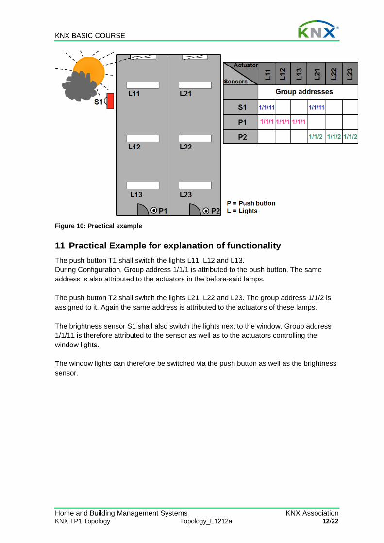
Figure 10: Practical example
11 Practical Example for explanation of functionality The push button T1 shall switch the lights L11, L12 and L13. During Configuration, Group address 1/1/1 is attributed to the push button. The same address is also attributed to the actuators in the before-said lamps. The push button T2 shall switch the lights L21, L22 and L23. The group address 1/1/2 is assigned to it. Again the same address is attributed to the actuators of these lamps. The brightness sensor S1 shall also switch the lights next to the window. Group address 1/1/11 is therefore attributed to the sensor as well as to the actuators controlling the window lights. The window lights can therefore be switched via the push button as well as the brightness sensor.
KNX BASIC COURSE
Home and Building Management Systems KNX Association KNX TP1 Topology Topology_E1212a 13/22
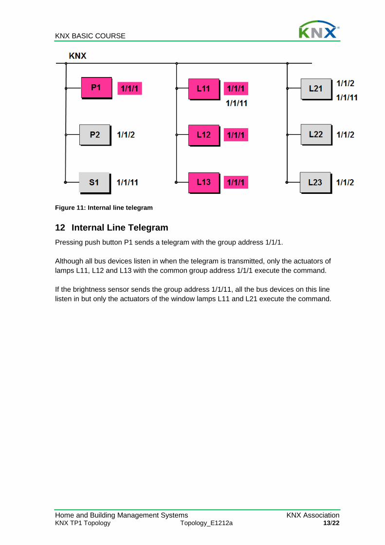
Figure 11: Internal line telegram
12 Internal Line Telegram Pressing push button P1 sends a telegram with the group address 1/1/1. Although all bus devices listen in when the telegram is transmitted, only the actuators of lamps L11, L12 and L13 with the common group address 1/1/1 execute the command. If the brightness sensor sends the group address 1/1/11, all the bus devices on this line listen in but only the actuators of the window lamps L11 and L21 execute the command.

KNX BASIC COURSE
Home and Building Management Systems KNX Association KNX TP1 Topology Topology_E1212a 14/22
Figure 12: Line-crossing telegram
13 Line-crossing Telegram If the brightness sensor is not connected in the same line as the lamp it has to control, it is necessary to transmit its telegrams via the main line. The parameters assigned to line coupler LC2 contain all the necessary information for this line coupler. LC2 is thus aware of the fact that there are bus devices outside its own “line 2” which respond to telegrams transmitted by the brightness sensor. LC2 therefore routes the group telegram 1/1/11 onto the main line. Line coupler LC1 is aware of bus devices on its “line 1” that respond to the group telegram 1/1/11 and therefore transmits the telegram to its line. All the bus devices on this line listen to the telegram from the brightness sensor but only the actuators of lamps L11 and L12 execute the command.

KNX BASIC COURSE
Home and Building Management Systems KNX Association KNX TP1 Topology Topology_E1212a 15/22
Figure 13: Area-crossing telegram
14 Area-crossing Telegram Even if brightness sensor S1 is assigned to a different function area, it can still address all bus devices through the backbone line. If the group address 1/1/11 is assigned to the brightness sensor, the telegram is routed to line 1 by backbone couplers BC1 and BC2 and line coupler LC1. The actuators of lamps L11 and L21 in function area 1/line 1 then execute the command.

KNX BASIC COURSE
Home and Building Management Systems KNX Association KNX TP1 Topology Topology_E1212a 16/22
Figure 14: Coupling unit: Routing counter
15 Coupling Unit: Routing Counter The telegram transmitted by the sending device contains a routing counter, of which the initial count value is 6. Each coupler decrements the routing counter and passes on the telegram as long as the value is not 0.The filter table entries are observed. If the service device, for example, transmits a telegram containing a routing count value of 7, the coupling units do not alter this value. In this case the filter table is ignored and all line couplers in the installation route the telegram. It finally reaches the bus devices it is intended for, no matter which line they are connected to. If the installation has a line-crossing structure, the routing counter limits the number of telegrams that cross lines.

KNX BASIC COURSE
Home and Building Management Systems KNX Association KNX TP1 Topology Topology_E1212a 17/22
Figure 15: KNX - Internal and External Interfaces
16 KNX – Internal and External Interfaces KNX is open to any other system. The backbone line (or any other line) can be connected via a gateway unit to e.g. SPS, ISDN, building management technology, Internet etc. The gateway unit carries out a bi-directional conversion of the protocol. The respective media couplers connect KNX media of different types (e.g. Twisted Pair 1 and Power Line 110). Parts of KNX installations can also be linked via optical fibres. The benefits of this are electrical isolation and greater cable lengths.

KNX BASIC COURSE
Home and Building Management Systems KNX Association KNX TP1 Topology Topology_E1212a 18/22
Figure 16: Division of lines in a medium-sized project (example)
17 Topology – Structure in building After the above theoretical introduction, some practical information (the above picture is by the way explained in detail in chapter “ETS Project Design – Advanced”). Ideally, a building does not have more than 50 bus devices installed per floor. Or one can – as shown in the above picture, make a division according to the different wings of the building. It is clear that in this case the better overview will be realised when line numbers correspond to floor numbers and area numbers correspond to building - or wing numbers.

KNX BASIC COURSE
Home and Building Management Systems KNX Association KNX TP1 Topology Topology_E1212a 19/22
Figure 17: The above picture is clearer with the required couplers
Of course it will not be possible to realize this under all circumstances. As line repeaters can be installed (as already indicated before), such a floor may be equipped with up to 253 devices, without having to violate the above structure (taking into account that line repeaters have to be counted double as discussed before, the normal maximum number of devices of 256 is reduced by 3). With that many devices it is possible to realize nearly any application, in view of the current evolution in the development of KNX devices and the availability of input - / output devices with in the mean while more than 16 channels.

KNX BASIC COURSE
Home and Building Management Systems KNX Association KNX TP1 Topology Topology_E1212a 20/22
Figure 18: Replacing line couplers by so-called “IP Routers”
18 Taking into account higher telegram rates: IP Network As explained in the previous paragraph, on all levels gateways to other systems can be installed. Increasingly, this is demanded in bigger projects as a result of higher customer demands. An important reason is the increased telegram load, which can occur when the user makes use of visualisation software and devices with a higher number of channels, all of which automatically returning multiple status acknowledgements.. In the latter case, a pure TP topology is overloaded due to the fact that transmission speed on main – and backbone lines is limited to 9,6 kBit / sec. In such a case one can easily use an IP network as a substitute for main – or backbone lines, by using the coupler that was designed for this purpose. As you can see from above picture, the main line has been replaced by an IP network. This has the advantage that all vertical operations e.g. the (bi-directional) communication between a building central and KNX is only determined by the bit rate of the secondary line (Ethernet is at least 1000 times faster; with the so-called “Gigabit” – switches it is possible to transmit data on the Ethernet 100 000 times faster). The parallel connection of several lines is no longer an issue. The standardized type of communication applied here is called “Tunnelling”. It is in other words the well-known gateway function, which is also

KNX BASIC COURSE
Home and Building Management Systems KNX Association KNX TP1 Topology Topology_E1212a 21/22
used by ETS for remote programming across IP. A building central can be connected simultaneously to several gateways, multiplying the total data rate. A different story is the direct communication between the individual KNX lines. The IP router makes use of another procedure which is called “routing”, or the actual line coupler function. Principally it works in the same way as routing across a TP main line: An IP router wanting to send a line-crossing telegram, will send this with a so-called “Multicast” IP address into Ethernet. All other IP routers are connected to this multicast address, and are able to receive and evaluate this telegram. The normal line coupler function is now again applied, i.e. the comparison with the compulsory filter table (group telegrams) or the line address (individual addressed telegrams) resulting in the ad hoc blocking or routing of telegrams. Please note the following with regard to multicast addresses:
a) There is a dedicated worldwide registered KNX multicast address, which is pre-programmed in the software of the IP router. This multicast address can be changed within the limits of the available address range for IP communication.
b) The network switch and area router in the LAN network must be fit to handle multicast telegrams. In case of doubt you should discuss this matter in advance with your network administrator.
c) The multicast addresses cannot be used across Internet, except across a VPN connection.
Our picture again: line couplers have now been replaced by IP routers. This picture represents the underneath explained case 1.

KNX BASIC COURSE
Home and Building Management Systems KNX Association KNX TP1 Topology Topology_E1212a 22/22
Just like the TP/TP coupler, the IP router can be used as a line coupler as well as a backbone coupler. If the IP router replaces the line coupler, all main lines and basically also the backbone line are replaced by Ethernet. (Case 1). If backbone couplers are replaced by IP routers, the normal line couplers can remain, as only the backbone line is replaced by the LAN (case 2). Which case is more appropriate depends more or less on the to be expected telegram rate requirements on main – and backbone lines. Theoretically, a third case is possible, as a combination of case 1 and 2, with normal TP areas with an IP router on top and also with lines with IP routers instead of line couplers. This option should however be chosen in exceptional cases. The topic is described in more detail in the KNX advanced course.
19 Limits to the use of IP routers Even if the high bit rate of Ethernet considerably facilitates heavy telegram traffic and minimizes telegram loss, one should warn not to thoughtlessly program bus devices sending out telegrams too frequently. The fast Ethernet will not help if for instance telegrams are sent out simultaneously from all lines into one single line. To explain it with a metaphor: the case would be similar to all cars accessing a 1000 lane motorway via 100 entries but all of them also wanting to exit via a single lane exit. This is by the way not a KNX related problem it is common to all mash structured data networks. Only a meaningful organisation of communication between bus devices and lines will be able to prevent a very unlikely but still possible loss of data. This however should be easily possible with sufficient knowledge on bus devices and their respective parameters.