knitting shells in the third dimension
TRANSCRIPT
Article Designation: Refereed JTATM Volume 3, Issue 4,Winter 2004
1
Volume 3, Issue 4, Winter2004
Knitting Shells in the Third Dimension
J. Power MA BSc ATI CTexT
Lecturer in Fashion Technology Manchester Metropolitan University
Department of Clothing Design and Technology Faculty of Food, Clothing and Hospitality
Hollings Campus Old Hall Lane
Manchester
E-mail: [email protected]
Abstract In order to produce textile structures intended for technical applications it is essential to have a full understanding of the geometrical properties and be able to guarantee exact replicas can be manufactured. This paper discusses some of the issues related to the controlled knitting of carbon yarn into three-dimensional 3-D shell shapes and the affect on the structural geometry. The study begins with an examination into the basic issues affecting the knitability of the selected yarn. Health and safety problems are addressed and the resultant carbon yarn was modified to reduce the chances of electrical failure due to conductive fibre fly. Initially two factors were considered relating to the structures geometry, however it was found that a third consideration was required when examining 3-D integrally knitted products. This study identified a maximum variation regarding the stitch length during knitting and devised a methodology to use when considering a yarn for use in 3-D shells. It was found that a two-phase approach was required when producing knitted 3-D shells, part mathematical and part empirical. Keywords: Knitting, Carbon, 3-D Shell, Technical, Textiles, Weft knitting.
Introduction Technical textiles are represented worldwide with many bespoke products and applications. However, in an increasingly competitive market, a mere presence in the sector is no longer enough to sustain the previously seen growth rates. It is essential for both industry and research to identify which textile sectors offer the best prospects and exploit them to their full potential for technical applications.
In past years, this category of textiles has been associated with extremely high modulus woven structures with high load bearing properties. These have been constructed from high tenacity, low elongation yarns. However, weaving has been increasingly challenged by other technologies such as warp knitting. In the mid 90’s it was acknowledged that various technical products required a different set of characteristics, which may be found in a weft knitted structure [1]. This created a demand for the speeding up of

Article Designation: Refereed JTATM Volume 3, Issue 4,Winter 2004
2
technological growth in the flat-bed knitting sector. The market place for flat-bed knitted technology was predicted to be an area of constant growth, especially within the field of technical textiles. According to the information available, knitted technical textiles currently represents about 9 % of the total fibre consumption used in technical textiles [2]. The technology has advanced to such an extreme in the last decade that the capabilities of the modern electronic flat-bed knitting machine now include the ability to produce 3-D seamless products, where the shaping is not necessarily restricted to the selvedge areas. 3-D shaping can be conducted integrally during flat-bed knitting, utilising a variety of shaping methods. This advancement in 3-D shaping has opened up a wide range of possibilities for technical knitted products. Aim The aim of the work presented in this paper was to establish an understanding into the knitting of the selected high performance yarn and the affect 3-D shaping has on the geometrical structure. Prior geometrical research has concentrated on two general areas regarding the definition of the final structures dimensions. The affects of the “stitch length”, and the consideration of the “stitch shape”. However, there is a third consideration when producing knitted 3-D shells, this is the “orientation” of the stitch. Within 3-D knitting it is necessary to change the orientation of the knitted stitch. From the literature review conducted to date this is an area understudied. However, it is of the utmost importance to understand this distortion in the structure especially within applications intended for the technical
sector, were a controllable geometry is essential. The modern flat-bed knitting machine benefits from an extremely versatile patterning range. Developments in recent years in CAD/CAM combined with machine improvements have made it a commercial possibility to produce complex mixtures of shaping and structure utilising a variety of techniques. These techniques have good potential for producing integrally shaped 3-D shells with a minimum amount of fibre waste. 3-D shells can be exploited in a variety of technical products and have obvious advantages were raw materials are costly or a continuous length of conductive yarn is required, to maintain an electrical circuit. This paper discusses 3-D shaping utilising carbon fibres and the geometrical relationships that occur in the structure as a direct result. Background The recent boom in the technical textile market has expanded the interest taken in the structural capabilities of textiles. Consideration has been given to the properties of strength, damage tolerance and ability to be fabricated to exact shell shapes. Generally technical textile products can be categorised by their production method; knit, weave, non-wovens or braids. Prior studies into 3-D shapes have examined fabricating a 3-D shell from a planar woven or knitted structure in the method described in Figure 1. One major problem identified in this method of production is the amount of wrinkles that occur when draping the structure. This is a result of the sheer deformation.
Figure 1 – Draping a 2-D Structure over a 3-D form

Article Designation: Refereed JTATM Volume 3, Issue 4,Winter 2004
3
In previous studies Authors [3] have made suggestions into how to overcome this deformation. One concept that has been presented was to produce a slacker structure. This enabled more internal movement to occur within the structure during 3-D draping, resulting in less defects occurring. Figure 2 illustrates the process of draping a
loose textile structure. It can be seen that there is an obvious difference in the geometrical properties were the structure has been stretched. Thus, resulting in reduced fibre volume in the given area, which in turn has a knock on affect with the overall geometrical properties.
Figure 2 – Draping a Slack Knitted 2-D Structure over a 3-D form
In order to obtain the harmonious geometry necessary for technical textiles the ideal solution would be to use a method of shaping which could be integrated with the textile manufacturing procedure. This would enable the deformation to occur as part of the structural mechanics, and eliminate the requirement for post draping. Various methods of achieving integral 3-D shaping utilising the manufacturing techniques were identified. However, many of the techniques of manufacture are limited to the resultant shape of the shell produced. Flat-bed knitting was selected as a suitable manufacturing process because it has the capability of producing goods with double curved surfaces such as cubes, cones and spheres, integrally during the knitting process. It is the only method of textile manufacturing that is versatile enough to perform complex shaping procedures without causing wrinkles and other defects within the structure and has the added benefit of low set-up costs. It has been identified that limited research has been conducted into the affects of 3-D shaping in flat-bed knitted structures. Previous studies include product related development which have resulted in various shapes being produced including; tubular elbows, boxes
and hemispherical forms. However, the advanced properties of the products appeared to receive more publication than the methodology that was necessary to produce shapes. It can thus be assumed that an empirical procedure was adopted to determine the actual dimensions of the 3-D form. Some attempts have been made to present mathematical modelling to determine the course to wale relationships required for various shapes [4]. However, none of these studies have acknowledged the fact that when utilising different fibre types within 3-D shaping the affects on the structural mechanics may differ. One problem that was investigated in this study was yarn control and the consistency of the amount of yarn delivered in each course. Yarn control is of the utmost importance if reproducible shell shapes are intended. In order to achieve a true geometrical understanding, the stitch length must be controllable during knitting. Objectives This paper is a result of three separate studies; the first part examined the knitability of carbon yarns and the resultant geometrical properties. The second part

Article Designation: Refereed JTATM Volume 3, Issue 4,Winter 2004
4
established a procedure for producing a knitting plan and finally the affect of 3-D shaping on the geometrical structure when using the technique of flechage (holding or partial knitting) was investigated. Part One: Knitting Carbon Due to the complexity of the knitting process, generally yarns with good stretch and bending properties are used. The selected carbon yarn was assessed for knitability on the 10 gauge Stoll CMS 330.6 flat-bed knitting machine. Problems were identified with the processing of the carbon yarn; these were related to the brittleness of the carbon fibres. It was acknowledged that there was a high possibility that fibre fractions (fly) would be produced during the knitting process. The fibre fractions were tested for health risks and were found to be outside the respirable range. However, there still remained a safety risk with the electrical components of the knitting machine. The carbon was thus substituted with a similar yarn with an electrical resistance in excess of 100 Mohms over 30 cm. An experiment was conducted to assess how much fibre fly was produced during knitting. The average fibre coverage from the fly produced during knitting was 2.6 %; this was totally unacceptable for safety reasons. A double nylon covering was applied to the actual spun carbon yarn and the yarn was knitted using the same parameters as the previous experiment. The average fibre fly coverage reduced to an average of 0.4 % as a direct result of the double nylon covering. This indicated that covering the carbon yarn eliminated fibre fly considerably and therefore reduced the chance of electrical failure due to conductive fly building up on the electrical components. Initially many problems were identified in terms of abrasion in areas were high frictional contact occurred. In an attempt to minimise the frictional forces generated the knitting machine was run at slow knitting speeds during the experimentation. Despite the fact that the covered carbon yarn had an high E-modulus and low elongation, it was knittable using the most direct yarn feed
path to eliminate any unnecessary frictional contact that may have disturbed the outer covering. The resultant structure is illustrated in Figure 3. Figure 3 – Knitted Carbon Structure
Fabric Dimensions Prior to the investigation into the 3-D shaping of the covered carbon yarn it was essential to gain an understanding into the structural geometry of the planar knitted structure. When examining the planar structure geometry it was identified prior that there were two factors to consider in order for a controlled geometry to be obtained.
• Size of the Stitch. • Shape of the Stitch.
One method of determining the size of the knitted stitch was to establish a stitch length measurement. It is common to obtain this measurement over a group of wales rather than a single stitch. In this study a calibration procedure was established to ensure each of the knitting machines stitch cams was delivering an identical amount of yarn (within reasonable variation) and a maximum acceptable variation value was established. It was found that for the covered carbon yarn the stitch cams required modification via the stitch cam adjustors (which are independently electronically adjustable). It was acknowledged that the most effective method to ensure the stitch lengths were consistent during the reciprocating cam box movement was to force the knitting into a single system. However, this was not a viable option when using the Sirix programming system because the Sirix software has been optimised to use as many knitting systems as possible to
Article Designation: Refereed JTATM Volume 3, Issue 4,Winter 2004
5
increase efficiency. It was therefore essential to determine a maximum acceptable course length variation value between the three knitting systems. No previous geometrical study has acknowledged that it is near impossible to obtain a totally consistent course length measurement from the flat-bed knitting machine. This study has addressed the problem by establishing a value of reasonable variation. Size of a Stitch The experimental investigation to determine the maximum course length variation found that a major influencing factor to ensure the course lengths were consistent (within reasonable variation) was yarn feed. Various yarn paths were examined in an attempt to determine the maximum level of control for the nylon covered carbon yarn. It was found that the selected yarn suffered from a relatively high coefficient of friction value and thus some yarn feed paths were unsuitable to deliver the nylon covered carbon yarn in a controlled manner. Therefore, auxiliary yarn feed equipment was necessary. It was found that the Nova storage feed unit provided sufficient control for the twisted carbon yarn. It was thus concluded from the experimental investigations that the three knitting systems independent of the travelling direction, could be calibrated within a maximum course length variation of 3.0 cm over 200 stitches, when following the procedure
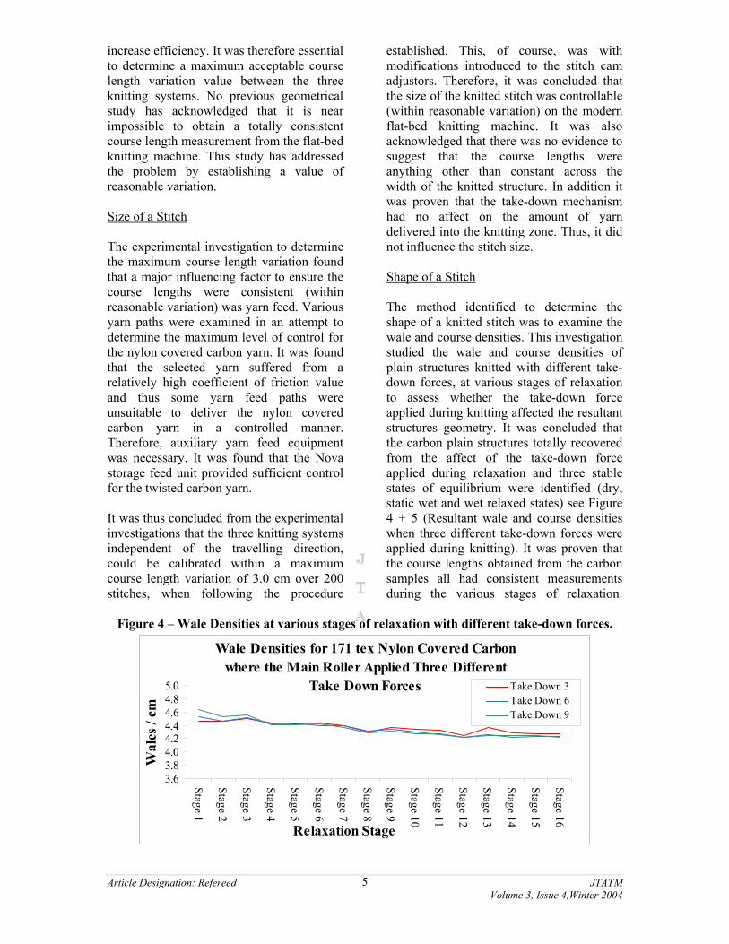
established. This, of course, was with modifications introduced to the stitch cam adjustors. Therefore, it was concluded that the size of the knitted stitch was controllable (within reasonable variation) on the modern flat-bed knitting machine. It was also acknowledged that there was no evidence to suggest that the course lengths were anything other than constant across the width of the knitted structure. In addition it was proven that the take-down mechanism had no affect on the amount of yarn delivered into the knitting zone. Thus, it did not influence the stitch size. Shape of a Stitch The method identified to determine the shape of a knitted stitch was to examine the wale and course densities. This investigation studied the wale and course densities of plain structures knitted with different take-down forces, at various stages of relaxation to assess whether the take-down force applied during knitting affected the resultant structures geometry. It was concluded that the carbon plain structures totally recovered from the affect of the take-down force applied during relaxation and three stable states of equilibrium were identified (dry, static wet and wet relaxed states) see Figure 4 + 5 (Resultant wale and course densities when three different take-down forces were applied during knitting). It was proven that the course lengths obtained from the carbon samples all had consistent measurements during the various stages of relaxation.
Figure 4 – Wale Densities at various stages of relaxation with different take-down forces.
Wale Densities for 171 tex Nylon Covered Carbon where the Main Roller Applied Three Different
Take Down Forces
3.63.84.04.24.44.64.85.0
Stage 1
Stage 2
Stage 3
Stage 4
Stage 5
Stage 6
Stage 7
Stage 8
Stage 9
Stage 10
Stage 11
Stage 12
Stage 13
Stage 14
Stage 15
Stage 16
Relaxation Stage
Wal
es /
cm
Take Down 3Take Down 6Take Down 9
Article Designation: Refereed JTATM Volume 3, Issue 4,Winter 2004
6
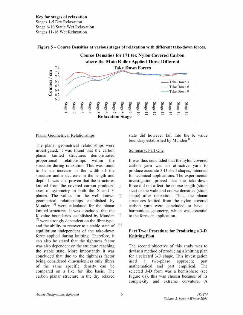
Key for stages of relaxation. Stages 1-5 Dry Relaxation Stage 6-10 Static Wet Relaxation Stages 11-16 Wet Relaxation Figure 5 – Course Densities at various stages of relaxation with different take-down forces.
Course Densities for 171 tex Nylon Covered Carbon where the Main Roller Applied Three Different
Take Down Forces
6.06.26.46.66.87.07.27.4
Stage 1
Stage 2
Stage 3
Stage 4
Stage 5
Stage 6
Stage 7
Stage 8
Stage 9
Stage 10
Stage 11
Stage 12
Stage 13
Stage 14
Stage 15
Stage 16
Relaxation Stage
Cou
rses
/ cm
Take Down 3Take Down 6Take Down 9
Planar Geometrical Relationships The planar geometrical relationships were investigated; it was found that the carbon planar knitted structures demonstrated proportional relationships within the structure during relaxation. This was found to be an increase in the width of the structure and a decrease in the length and depth. It was also proven that the structures knitted from the covered carbon produced axes of symmetry in both the X and Y planes. The values for the well known geometrical relationships established by Munden [5] were calculated for the planar knitted structures. It was concluded that the K value boundaries established by Munden [5] were strongly dependent on the fibre type, and the ability to recover to a stable state of equilibrium independent of the take-down force applied during knitting. Therefore, it can also be stated that the tightness factor was also dependent on the structure reaching the stable state. More importantly it was concluded that due to the tightness factor being considered dimensionless only fibres of the same specific density can be compared on a like for like basis. The carbon planar structure in the dry relaxed
state did however fall into the K value boundary established by Munden [5]. Summary: Part One It was thus concluded that the nylon covered carbon yarn was an attractive yarn to produce accurate 3-D shell shapes, intended for technical applications. The experimental investigation proved that the take-down force did not affect the course length (stitch size) or the wale and course densities (stitch shape) after relaxation. Thus, the planar structures knitted from the nylon covered carbon yarn were concluded to have a harmonious geometry, which was essential to the foreseen application. Part Two: Procedure for Producing a 3-D Knitting Plan The second objective of this study was to devise a method of producing a knitting plan for a selected 3-D shape. This investigation used a two-phase approach; part mathematical and part empirical. The selected 3-D form was a hemisphere (see Figure 6a), this was chosen because of its complexity and extreme curvature. A
Article Designation: Refereed JTATM Volume 3, Issue 4,Winter 2004
7
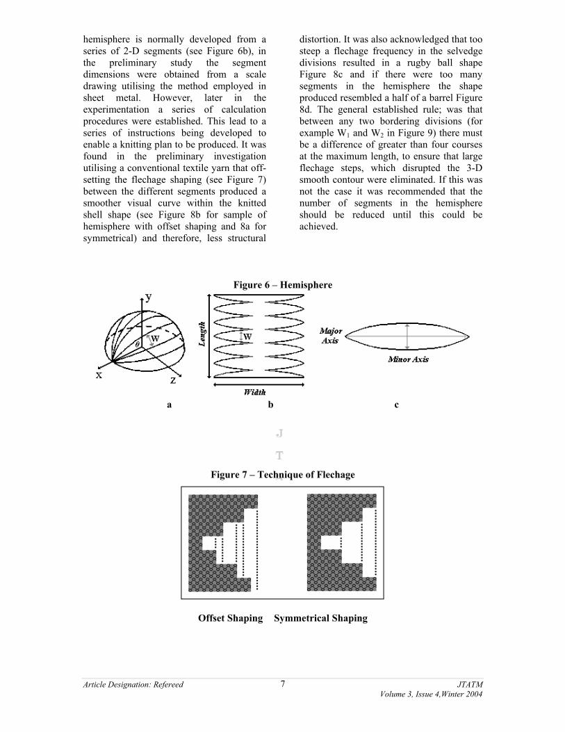
hemisphere is normally developed from a series of 2-D segments (see Figure 6b), in the preliminary study the segment dimensions were obtained from a scale drawing utilising the method employed in sheet metal. However, later in the experimentation a series of calculation procedures were established. This lead to a series of instructions being developed to enable a knitting plan to be produced. It was found in the preliminary investigation utilising a conventional textile yarn that off-setting the flechage shaping (see Figure 7) between the different segments produced a smoother visual curve within the knitted shell shape (see Figure 8b for sample of hemisphere with offset shaping and 8a for symmetrical) and therefore, less structural
distortion. It was also acknowledged that too steep a flechage frequency in the selvedge divisions resulted in a rugby ball shape Figure 8c and if there were too many segments in the hemisphere the shape produced resembled a half of a barrel Figure 8d. The general established rule; was that between any two bordering divisions (for example W1 and W2 in Figure 9) there must be a difference of greater than four courses at the maximum length, to ensure that large flechage steps, which disrupted the 3-D smooth contour were eliminated. If this was not the case it was recommended that the number of segments in the hemisphere should be reduced until this could be achieved.
Figure 6 – Hemisphere
a b c
Figure 7 – Technique of Flechage
Offset Shaping Symmetrical Shaping

Article Designation: Refereed JTATM Volume 3, Issue 4,Winter 2004
8
Figure 8 – Knitted Hemispheres
a b
c d
Figure 9 – Segment
Phase One – Mathematical Approach Initially a 3-D coordinate system was defined whereby the X-axis was the width of the knitted structure, the Y-axis was the length and the Z-axis was the height (See
Figure 6a). A single segment of a hemisphere was considered and a generalised equation was derived to define the length of the arc (W) at various points along the width of the segment (see Figures 6a, 6b and 9).
( )s inrW
nπ θ
=
…(1)

Article Designation: ITMA JTATM Volume 3, Issue 3,Fall 2003
9
Where r is the radius of the intended hemisphere, n is the number of segments in a hemisphere and theta is determined by the angle of the hypotenuse from the selected segment length to the origin of the hemisphere (see Figure 10).
Figure 10 – Diagram to Determine Theta
The preliminary samples utilising a conventional yarn found that a six-segment hemisphere produced the smoothest curve when the radius was calculated to be 7.5 cm. It was thus decided to investigate a series of sizes of hemispheres using the nylon covered carbon yarn. Equation 1 was utilised to determine the appropriate measurement for each segment division to enable a knitting plan to be produced. The sizes of hemispheres were calculated to achieve diameters of 15, 16, 17, 18, 19, 20 and 25 cm.
Phase Two – Knitting Plan In order to calculate a knitting plan successfully it was necessary to determine a suitable wale and course density. It was found that the most practical method of obtaining the wale and course densities was to use those established in the selected state of equilibrium from the planar structure. Although it was reasonable to assume some modification would occur within the structures geometry due to the shaping, at this stage this was only an assumption. An immediate problem was identified in converting the calculated dimension of the segment into courses and wales via the densities obtained from the planar structure. This was, that it was impossible to knit part-
courses and wales. Therefore, the number of courses/wales obtained required rounding to the nearest integer. An algorithm was devised to ensure this was done consistently within each division for the width of the segments. It has been identified that it was vastly more complex to devise an algorithm to distribute the courses between the segments. This was due to the flechage shaping demanding two complete courses per step and all the segments required the total amount of courses to be even in the minor axes (Figure 6c). A generalised methodology was therefore devised to calculate the amount of courses in the outer arcs at various points (divisions) on the surface of the hemisphere. The algorithm and the established methodology were successfully proven for a range of sizes of hemispheres. Finally a procedure for allocating the shaping frequency to a single segment was described, this was a somewhat empirical exercise to ensure the 2-D knitting plan was capable of being transferred to the knitting stage successfully. The study as described in Part Two successfully defined a method of calculating a hemisphere shape and a series of procedures to enable a 2-D knitting plan to be realised. The selected shell was a hemisphere; this was the most difficult shape to produce. It was concluded that it would be impossible in the allocated timescale of the project to present a mathematical method of developing a 3-D knitted shell shape. Therefore, a two-step approach was used, part mathematical and part empirical. The established procedure is described in Figure 11. Part 3: Effects of 3-D Shaping on the Geometrical Dimensions. Various methods of determine how 3-D shaping affected the geometrical dimensions of the knitted shell, were investigated during this study. It was found that the most reliable method of obtaining the wale and course densities was to model the structure over a former of the intended size of knitted hemisphere. For ease of comparing data obtained from the different sizes of
Article Designation: Refereed JTATM Volume 3, Issue 4,Winter 2004
10
hemispheres the former utilised in the experimental study was a balloon inflated to the correct dimensions. The Author accepts that this is likely to stretch the knitted structure in width, but at this time no other alternative method of analysis is available. More recent studies include the use of CCD and image analysis packages to determine the structures geometry [6]. However, this development is very much in its experimental stages and has only recently been applied to planar knitted structures, where stitch orientation is not as critical. The results of the wale and course densities obtained using the described method demonstrated that there was a general pattern occurring in the structures geometry independent of the dimensions of the knitted hemispheres (see Figure 12). This was related to the division where the densities were obtained from within the segment (see Figure 9). The wale and course densities obtained from the centre divisions of the hemisphere (where the least shaping
occurred in the segment) were nearer to those obtained from the planar structure; whilst the selvedge divisions decreased in course density and increased in wale densities (area where most shaping occurred). Thus, the knitted dimensions decreased in the width and increased in the length at the selvedges. It was therefore concluded that the amount of 3-D shaping does affect the structural geometry within the knitted hemisphere. This research proves that when examining knitted structures for technical textile applications there are three important factors to consider.
• Stitch Size (Stitch Length)
• Stitch Shape (Stitch Density)
• Stitch Orientation (3-D Configuration)

Article Designation: Refereed JTATM Volume 3, Issue 4,Winter 2004
11
Figure 11 – Established Procedure for the Development of a 3-D Knitted Shell.
Establish a suitable yarn feed path for the high performance yarn
Ensure the knitting systems are calibrated (stitch size)
Determine the stitch shape (wale and course density), ensuring a harmonious
geometry can be achieved
Calculate appropriate dimensions for the 2-D development of the
hemispheres
Develop the 2-D knitting plan
Empirical optimisation of the knitting plan to enable successful knitting
Final product: 3-D knitted hemisphere, produced from a high performance yarn for a technical
textile application

Article Designation: Refereed JTATM Volume 3, Issue 4,Winter 2004
12
Figure 12 – Wale and Course Densities Obtained from the Divisions of the Hemispheres
4.00
4.20
4.40
4.60
4.80
5.00
5.20
5.40
5.60
1 2 3 4 5 6Divisions
Wal
es p
er c
m
15 cm Knitted HemispherePlanar Wale Density16 cm Knitted Hemisphere17 cm Knitted Hemisphere18 cm Knitted Hemisphere19 cm Knitted Hemisphere20 cm Knitted Hemisphere25 cm Knitted Hemisphere
6.00
6.20
6.40
6.60
6.80
7.00
7.20
7.40
7.60
1 2 3 4 5 6Divisions
Cou
rses
per
cm
15cm Knitted HemispherePlanar Course Density16 cm Knitted Hemisphere17 cm Knitted Hemisphere18 cm Knitted Hemisphere19 cm Knitted Hemisphere20 cm Knitted Hemisphere25 cm Knitted Hemisphere
Conclusion The work described in this paper outlined the difficulties in producing products for technical applications. The initial aim of the work was to knit the selective high performance yarn (carbon) into a 3-D shell for a technical application. However, it was found during the initial investigation that this was an area that was understudied. Therefore, prior to meeting the initial aim, much work was required to gain an understanding into yarn control methods and geometrical dimensions. This paper has addressed various issues including the yarn delivery and the health and safety of knitting a conductive yarn. The two important geometrical factors were considered; stitch size and stitch shape, however, a further factor was identified as being of fundamental importance during 3-D shaping, “the orientation”. It was found that even though the carbon yarn could be delivered within a maximum variation value of 3 cm per 200 needles and in the planar state the geometry was considered as harmonious, the affect of 3-D shaping was apparent in the resultant structural geometry. Further research is required into this area to
assess how controllable this distortion is and could this distortion be predicted for prior to the knitting stage? This is an area were much research is required. References 1) Hong, H et al., Minho University Paper. The Development of 3D Shaped Knitted Fabrics for Technical Purpose on a Flat Knitting Machine. P.1 – 9. 2) De Arajo, M. et al., (2002) Textile Asia. Weft-knitting Fabric Design for Technical Applications. 33, (3), P.23 – 27. 3) Potluri, P el al., (2001) Composites: Part A Applied Science and Manufacturing. Comprehensive Drape Modelling for Mould 3-D Textile Preforms. 32, P.1415 – 1424. 4) Heenkenda, N. K. (1999) Unpublished PhD Thesis. A Study of Using Weft Knitted Structures for Composites. 5) Munden, D. L., Leigh, B. G. and Chell, F. N., (1963) Journal of the Textile Institute and Industry. Dimensional Changes During Washing of Fabrics Knitted From

Article Designation: Refereed JTATM Volume 3, Issue 4,Winter 2004
13
Wool/Man-made Fibre Blends. 54, P. 135 – 145.
6) Abou-iiana, M.et al,. (2003) Textile Research Journal. Assessing Structural Changes in Knits During Processing. 73, P.535