kiwi panoramic tripod head -...
TRANSCRIPT

User’s Guide - V1.1 - 12 Jan 2005
KiWi Panoramic Tripod Head™

KiWi Panoramic Tripod Head Overview
Thank you for purchasing a Kaidan KiWi™ Panoramic Tripod Head. This manual is designed to help you understand how to use your KiWi to create quality panoramas. This docu-ment will be revised occasionally and updated versions can be downloaded from the KiWi page on the Kaidan web site.
Kaidan popularized panoramic VR/QTVR panoramic photography with our KiWi™ tripod head more than 8 years ago. The new KiWi contin-ues that tradition with an affordable, rugged, lightweight and elegant design that includes an innovative detent click-stop mechanism (10, 12, 14, 16, 18, 20 stops are standard; 2 through 28 stops optional), handy Click-Disc storage accessory pouch with number-of-shots chart, built-in bubble level and an adjustable camera bracket. The KiWi is also easily upgradeable with optional camera brackets to sup-port fisheye lenses and quick-release camera mounts.
While the KiWi will be an excellent choice for many photographers just getting started in panoramic photog-raphy, it will also appeal to profes-sionals who require a compact and
Welcome to the Kaidan KiWi and Panoramic Photography
lightweight travelling companion.The KiWi is built around a sturdy and precise Rotator Base with inter-changable ClickDiscs. There are interchangeable camera brackets that slide and lock onto the Rotator Base.
The KiWi makes it easy to capture a sequence of photos that are stitched to form a complete panoramic image. It holds the camera in the optimum portrait orientation, positions the camera so that it rotates around the optical center or nodal point of the lens and provides a repeatable and ad-justable click-stop indexing mechanism.
The KiWi is designed to handle a wide range of digital and film cameras as well as conventional wide-angle and fisheye lenses. You'll be able to use any stitching or panoramic application available, such as those from Apple, iSeeMedia, iPIX, VR Toolbox, Realviz, Panotools and Easypano because the KiWi is adaptable to handle any situa-tion, camera, lens or software.
1

The KiWi Family
Compact Camera Bracket & Twin-Axis Adapter (Optional)
The Compact Camera Bracket and the Twin-Axis Adapter are designed to support most digital and film cameras that are equipped with fisheye lenses, and will also appeal to those users who desire two independent axes of adjustment. The two axes of adjustment positions the lens in such a manner so as not to capture any more of the Rotator Base than necessary. When a camera equipped with a circular fisheye lens is installed on the bracket, only a small segment of the Rotator Base will appear in the image. These features are ideal for those using iPIX software, Panoweaver (www.easypano.net) and other software applications that use fisheye images.
Standard Camera Bracket
The Standard Camera Bracket is designed to support most digital and film cameras in a portrait orientation. Used primarily to shoot single-row or cylindrical panoramas, the Standard Camera Bracket can be adjusted along the horizontal arm of the Rotator Base in order to locate the camera in the side-to-side orientation. There are three slots in the bracket, that when used with various positioning aids, provide for the fore-aft adjustment of the camera's optical center, or nodal point, over the rotational center of the tripod head.
KiWi Rotator Base & Accessory Pouch
The primary component in the KiWi family is the Rotator Base. The base uses interchange-able indexing discs called ClickDiscs that provide various click-stop positions. The base contains an integral circular bubble level and ac-commodates either 1/4” or 3/8” tripod threads. Included with every KiWi is a convenient Ac-cessory Pouch. The pouch is used to store your ClickDiscs, set screw wrench and can also be used to store memory cards and other small items. The pouch has a handy "Number of Shots" chart which will help you determine which disc to use and how many shots to take.
Introducing the KiWi Components
Optional Quick Release Camera Brackets
The Standard and Twin-Axis Camera Brackets have optional Quick Release Camera Brackets. Based on the popular Arca-Swiss standard, the Quick Release Brackets provide an elegant and lightweight solution for quick and repeatable installation and removal. Arca-compatible camera plates are available for most popular cameras. The plates typically attach to the bottom of your camera using the tripod mounting thread. Most plates have 1/4-20 tapped holes to still provide a way for you to attach the camera to a tripod. This option is ideal for those photographers who shoot with multiple cameras or need to remove the camera from the head for conventional photography.
2
Rotator Base
Standard Camera Bracket
Compact Camera Bracket & Twin-Axis Adapter
OptionalQuick Release Brackets
Accessory Pouch

KiWi ClickDiscs
Disassembly
1) The Rotator Base is held together with a recessed set screw which is located at the zero degree position on the barrel. Use the set screw wrench lo-cated in the blue accessory pouch and loosen the set screw (do not remove) by turning several revolutions counter-clockwise.
2) With the set screw loosened, remove the axle by pulling up on the knob which contains the bubble level.
3) The axle has a thin plastic washer. This washer should always go between the knob of the axle and the horizontal plate. Leave the plastic washer on the axle.
4) You can remove the ClickDisc from its cavity in the top of the indexing barrel by pulling up on the tab of the ClickDisc.
How to install and remove ClickDisc indexing discs
3
Barrel w/ClickDisc Installed
Set Screw Wrench in Barrel
Rotator Base Assembly ClickDisc Accessory Pouch with 6 ClickDiscs and Set Screw Wrench

KiWi ClickDiscs
Assembly
1) Install the appropriate ClickDisc into the cavity on the top of the barrel. Be sure to orient the tab of the ClickDisc into the notch of the barrel. Push the ClickDisc into posi-tion.
2) Place the horizontal plate over the barrel and reinsert the axle. Make sure that the plastic washer is on the axle.
3) Push down on the knob of the axle to compress the as-sembly and to retract the spring plunger fully. As you apply pres-sure on the knob, use the set screw wrench to tighten and se-cure the axle in position. There should be no discernable play between the barrel and plate.
4) You may find it easier under certain circumstances to unscrew and retract the spring plunger just a bit. It will be easier to compress the assembly this way. Be sure to readjust the plunger afterwards.
How to install and remove ClickDisc indexing discs
4
Barrel w/ClickDisc Installed
Set Screw Wrench in Barrel
Axle w/PlasticWasher
Horizontal Plate
BarrelClickDisc
Set Screw Wrench
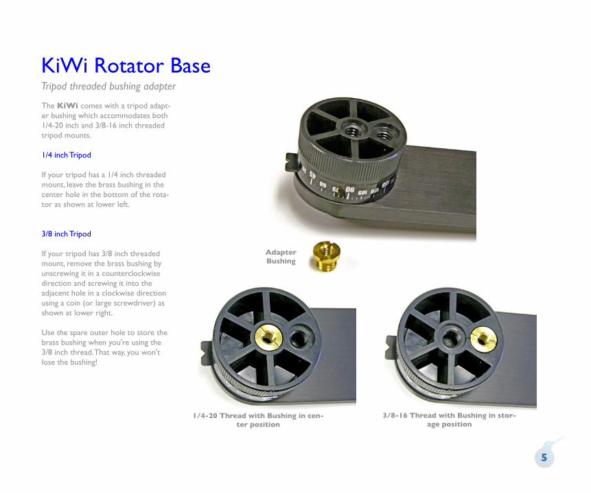
KiWi Rotator BaseTripod threaded bushing adapter
The KiWi comes with a tripod adapt-er bushing which accommodates both 1/4-20 inch and 3/8-16 inch threaded tripod mounts.
1/4 inch Tripod
If your tripod has a 1/4 inch threaded mount, leave the brass bushing in the center hole in the bottom of the rota-tor as shown at lower left.
3/8 inch Tripod
If your tripod has 3/8 inch threaded mount, remove the brass bushing by unscrewing it in a counterclockwise direction and screwing it into the adjacent hole in a clockwise direction using a coin (or large screwdriver) as shown at lower right.
Use the spare outer hole to store the brass bushing when you're using the 3/8 inch thread. That way, you won't lose the bushing!
5
AdapterBushing
1/4-20 Thread with Bushing in cen-ter position
3/8-16 Thread with Bushing in stor-age position
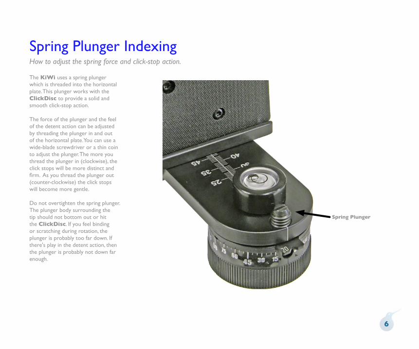
Spring Plunger IndexingHow to adjust the spring force and click-stop action.
The KiWi uses a spring plunger which is threaded into the horizontal plate. This plunger works with the ClickDisc to provide a solid and smooth click-stop action.
The force of the plunger and the feel of the detent action can be adjusted by threading the plunger in and out of the horizontal plate. You can use a wide-blade screwdriver or a thin coin to adjust the plunger. The more you thread the plunger in (clockwise), the click stops will be more distinct and firm. As you thread the plunger out (counter-clockwise) the click stops will become more gentle.
Do not overtighten the spring plunger. The plunger body surrounding the tip should not bottom out or hit the ClickDisc. If you feel binding or scratching during rotation, the plunger is probably too far down. If there's play in the detent action, then the plunger is probably not down far enough.
6
Spring Plunger

Standard Camera Bracket - Camera MountingMounting your camera on the Standard Camera Bracket
To mount your camera, first select the appropriate slot in the bracket that will best locate the tripod mount-ing thread on your camera. You may need to reposition the camera knob. To remove the knob simply slide it along the slot to the end that has the threaded hole. Unscrew the knob out of the threaded hole, being careful not to crossthread. Replace the knob into the appropriate slot by reversing the procedure. The camera knob is a two piece design, with an inner and outer knob. Before installing the camera knob in the Standard Camera Bracket, turn the inner knob clock-wise into the outer knob until it won’t turn anymore. Next, install the knob into the appropriate slot then into the tripod mounting hole of your camera. Turn the inner knob into the camera until it bottoms out, then turn the outer knob clockwise until the camera is tight on the bracket.
The Standard Camera Bracket comes with two camera positioning aids. There is a flat camera shoe and a right-angle lug that slide and lock along any of the three slots. These are used as aids to keep your camera perpendicular and also serve as a placeholder for you to re-attach your
camera in the same location. Slide these adjusters into the best spot on your camera to ensure a square and secure mounting.
The Standard Camera Bracket also has an innovative DiamondGrip surface on the camera mounting side. This special friction surface will help to hold your camera's base securely to the bracket without slippage.
The left-right adjustment to center your lens over the pivot point is ac-complished by loosening the purple knob and sliding the bracket. Be sure to tighten the knob to lock the brack-et in place. The fore-aft adjustment is made by loosening the camera knob and sliding the camera along the slot.
7
Camera Shoe
Camera Lug
Camera Knob
Left-RightAdjustment Knob
DiamondGripSurface
CameraShoe

Compact Camera Bracket & Twin-Axis Adapter (Optional)Mounting your camera on the Twin-Axis Camera Bracket
The Compact Camera Bracket is offered as an optional choice when purchasing a KiWi. You can also purchase it separately. When used with Twin Axis Adapter, it provides two separate axes of adjustment. This makes it easier to slide the camera into the proper position in order to locate the nodal point over the axis of rotation. There are two sliding and locking adjustments with purple lock-ing knobs.
This bracket is also the best choice for those who use fisheye lenses. Since the camera's optical axis is inline with the main horizontal plate, the only part of the tripod head which appears in the shot with a circular fisheye lens is a small semicircular portion of the base.
The Compact Camera Bracket has three threaded holes for the Camera Knob. Use the hole that is most ap-propriate for your particular camera.
The modular construction of the makes it easy to loosen the adjust-ment axes and quickly remove the various elements. There are conve-nient measurement scales in both axes to ease reassembly.
An optional Arca-style Quick Release plate is available as an option for the Compact Camera Bracket. It can be purchased with the bracket or pur-chased and installed at any time.
You can also purchase the Twin-Axis Adapter separately and use it with the Standard Camera Bracket (as shown below). This provides additional mounting surface area and the use of lugs and shoes to help retain the cam-era. This is a better choice for those not using a quick-release plate.
8
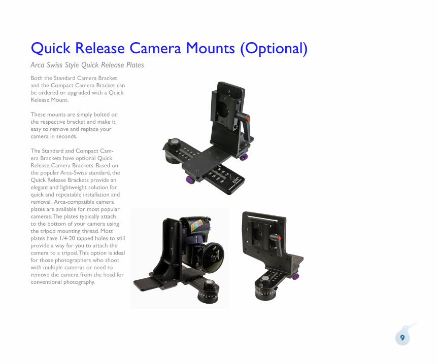
Quick Release Camera Mounts (Optional)Arca Swiss Style Quick Release Plates
Both the Standard Camera Bracket and the Compact Camera Bracket can be ordered or upgraded with a Quick Release Mount.
These mounts are simply bolted on the respective bracket and make it easy to remove and replace your camera in seconds.
The Standard and Compact Cam-era Brackets have optional Quick Release Camera Brackets. Based on the popular Arca-Swiss standard, the Quick Release Brackets provide an elegant and lightweight solution for quick and repeatable installation and removal. Arca-compatible camera plates are available for most popular cameras. The plates typically attach to the bottom of your camera using the tripod mounting thread. Most plates have 1/4-20 tapped holes to still provide a way for you to attach the camera to a tripod. This option is ideal for those photographers who shoot with multiple cameras or need to remove the camera from the head for conventional photography.
9

Nodal Point
This is one of the most frequently asked questions when it comes to stitcher-based panorama creation. Once you understand the basics, you’ll be able to easily locate the nodal point for any camera and lens combination.
Simply put, the nodal point is the point inside your camera where the light rays converge and flip over. When shooting a panorama it’s necessary to rotate about this point to eliminate the image mismatch caused by parallax error.
It’s also worth noting that the nodal point is not the same as the film plane, which is often marked on the underneath side of many 35mm cameras. Generally, for most 35mm cameras and lenses, the nodal point is located somewhere towards the center of the lens barrel.
Parallax error can be easily demonstrated by this simple experiment. Close one eye and hold your index finger upright about six inches away from your open eye. Rock your head from side to side. Notice how your finger moves with respect to the background. This relative movement is due to the fact
that you’re not rotating your head around your eye’s nodal point, which is somewhere in the center of your eyeball. Instead, you’re rotating about your spine which is several inches to the rear and off to one side. It is this relative side-to-side motion that we will strive to eliminate when setting up a camera for VR panoramas.
Step 1: The side-to-side adjustment
Once your camera is fastened to your camera bracket, move to the front of the tripod head so you’re looking into the lens. Adjust the camera bracket so that the center of the lens is directly over the pivot axis of the tripod head. Try to be as accurate as possible. You should strive to get this adjustment within plus/minus a 1/16th of an inch.Step 2: Fore-Aft Adjustment
This step is most easily accomplished out of doors. Find a vertical edge or line, such as a doorway or edge of a building. Position your camera and tripod about 2-1/2 feet away, or as close as possible with the edge still in focus when you look through the viewfinder.
Looking through the camera’s
What is it and how do I find it?
Parallax error can be easily demonstrated. It’s the relative move-ment caused by a shifting point of view. In this example, you eye is moving with respect to your hand and the background.
10

Nodal Point (continued)
viewfinder, find another vertical edge or line that is far away, such as another building or telephone pole. Align the two objects and rotate the pan head so they are in the left hand side of the viewfinder.
Rotate the pan head so the two objects move over to the right hand side of the viewfinder. Unless you’ve managed to unwittingly locate the right position, you should notice the two objects will move with respect to each other as you rotate the pan from left to right. Slide the camera to the front or rear as required to eliminate this relative movement.
Step 3: Record Your Results
After you’ve discovered the two location dimensions, be sure to record the settings. The KiWi has convenient indicator scales for this purpose. These numbers represent the nodal point for this given camera and lens combination. If you change cameras or lenses, this procedure may have to be repeated
Step 5: How About Rangefinder Cameras?A rangefinder camera is a camera
If, as shown above, the two objects move with respect to one and another in the viewinder, slide the camera fore or aft in order to eliminate this movement. Here, the telephone pole has moved behind the brick wall.
where you look through a separate viewfinder and not through the actual lens. The process is basically the same. Locate the Side-to-Side adjustment as discussed in Step 1. When it comes to the Fore-Aft adjustment, you won’t be able to look through the viewfinder to determine the proper setting since the viewfinder is a separate optical path that doesn’t really “see” the same image as the film.
Instead, you’ll have to start with the bracket all the way to the front and take pairs of test shots. Each pair will have the vertically aligned objects in the left and then the right side of the viewfinder. After each pair of photos, slide the bracket rearward and repeat the process. Slide the bracket the same increment each time (i.e. 10mm). Be sure to record the scale setting for each pair of images. Process the film, or in the case of digital cameras, download the images to your computer.
At the end of this process you will be able locate the pair of images with the least relative movement. If no single image is optimum, you may need to interpolate between two images to find the closest value.
What is it and how do I find it?
Looking through the viewfinder align a close object (brick wall) with a faraway object (telephone pole). As you rotate the camera from side-to-side there should be no relative movement between the two objects as shown to the right.
11

Shooting Panoramas
How much Overlap?
The amount you turn the camera for each shot varies. It is dependent on a number of factors such as the field of view (the angle) of your camera and lens, as well as which program you intend to use. For example, with iSeeMedia PhotoVista, VR Toolbox VR Worx or Apple's QuickTime VR Authoring Studio, the recommended image overlap is anywhere from one-quarter to one-half. That’s a good rule of thumb for most stitching applications. You should check with the recommendations of the software that you intend to use in order to determine overlap requirements.
How many Shots?
Once you’ve determined the overlap, you’ll be able to figure out how many shots. The easiest way to do this is to simply look through the viewfinder and turn the camera to achieve the desired amount of overlap. You then check the angle readout to see how far you turned the camera. Round the angular value to the nearest convenient value. For most stitching programs, it is generally not that important to use a precise overlap value. However, it should be noted that some programs are more sensitive to an overlap value that constantly repeats from shot to shot. You may need to experiment somewhat to
How do I begin?
obtain the best results.
Taking the Photos
When you’re ready to shoot, make sure that the camera is securely attached to the KiWi. You should use a tripod that is sturdy, ideally one that has a center support system of braces to help keep the camera from flexing.
Proper leveling is important and often misunderstood. When it comes to leveling there are two things that are fairly important. With multirow panoramas (i.e. Realviz Stitcher) the issue of leveling is less crucial and primarily involves aestethics and placement of the horizon. We’ll concentrate primarily on cylindrical or single-row panoramas.
First, the camera's optical axis should be parallel with the rotation plane of the tripod head. In other words the camera should not be pointed up or down with respect to the plane of rotation.
Secondly, it's also somewhat important for the camera and film/CCD to be properly aligned with respect to rotation when viewed from the front (looking into the lens).
This can happen because the camera is not seated flush against the upright bracket. This
is pretty common since many cameras have mounting screws that are not in the center of the base. Many cameras have screws off to one end of the camera or at the edge of the camera and this can cause the camera to not be pulled down evenly onto the tripod head mounting plate.
Another problem is that CCDs may not be accurately positioned within the camera body and respect to the mounting surface. It only takes a fraction of a degree and, with other manufacturing tolerances, this can add up to be noticeable.
This misalignment can also happen if the upright bracket is bent or is not exactly perpendicular to the rotation plane of the head. At Kaidan we check this dimension very closely to ensure it's as close to 90° as reasonbly possible.
The effect of a rotated camera (when viewed looking into the lens) is a stairstepping of images as you progress around the panorama. Stairstepping has nothing to do with the state of the entire head being level with respect to the horizon. This can be corrected by rotating all the images a slight amount in your authoring program.
You can also shim the camera/head to compensate for such misalignment errors as well. A few layers of tape is usually all that
12

Shooting Panoramas (continued)How do I begin?
it takes. Let me also reiterate what's not as important as some people think.
The overall level of the head/camera is not as critical in order to produce good stitched results. As long as the camera is not tilted or rotated and as long as the camera is positioned so that the optical axis is parallel to the rotation plane, you can tilt or position the entire head so that it's not level to the horizon and it won't affect the image.
Now, it might produce a panorama that is tilted with respect to the horizon but that might be an artistic choice or something you want to do on purpose.
As long as the optical axis is parallel to the rotation plane and the camera/CCD is not rotated, slight variations in level as the head rotates is generally not a problem.
As you shoot around the circle, try to avoid capturing any moving objects that might come into your field of view. There is no harm in waiting, for example, while a person walks past before shooting the photo.
You may also want to check with the software developer of the stitching software that you’re using to get their recommendations for exposure settings and other camera settings.We hope you enjoy shooting your panoramas
and if you have any questions or problems using our equipment, please let us know.
13

Specifications and DimensionsKiWi with Standard Camera Bracket
14
97 mm
17 mm120 mm
180 mm
148 mm
178 mm
Min
Max
7 mmMin
Max

Specifications and DimensionsKiWi with Standard Camera Bracket and Quick Release Mount
15
97 mm
180 mm
148 mm
178 mm
Min
Max
7 mmMin
Max2 mm
105 mm
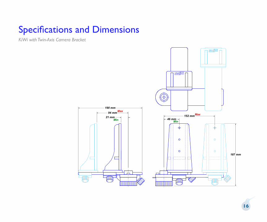
Specifications and DimensionsKiWi with Twin-Axis Camera Bracket
16
21 mm
94 mm
190 mm
46 mm152 mm
187 mm
Min
Max
Min
Max

Specifications and DimensionsKiWi with Twin-Axis Camera Bracket and Quick Release Mount
17
190 mm
46 mm152 mm
187 mm
Min
Max
Min
Max6 mm
79 mm
Warranty and Product Return InformationCopyright © 2004 Kaidan, Inc. All Rights Reserved. First Edition, Sep 2004. KiWi, QuickPan is a trademark of Kaidan, Inc. Other products mentioned herein may be trademarks of their respective companies. Patents Pending.
Information in this manual is subject to change without notice and does not represent a commitment on the part of Kaidan. No part of this manual may be reproduced or transmitted in any form or by any means, electronic or mechanical, including photocopying, recording, or information storage and retrieval systems, or translated to another language, for any purpose other than the licensee’s personal use and as specifically allowed in the licensing agreement, without the express written permission of Kaidan.
Kaidan Warranty and Return Policy
A • Limited Warranty
In the event of a defect in materials or workmanship, Kaidan will repair the product with new or rebuilt parts for a period of three-hundred and sixty five (365) days from the date of original purchase. Such work will be performed free of charge. Follow the Product Return Procedure (Section D following). Likewise, any software purchased from Kaidan also comes with a one year warranty if your disc or media is defective or damaged. This warranty is extended only to the original purchaser and is not transferable. A purchase receipt or other proof of original purchase will be required before warranty performance is rendered. This warranty only covers failures due to defects in materials or workmanship which occur during normal use. It does not cover damages or failures which are caused from accident, misuse, abuse, neglect, mishandling, misapplication, alteration, faulty installation, modification, service by anyone other than an authorized representative of Kaidan, Acts of God, or by products not supplied by Kaidan.This warranty covers any damage incurred during original shipment of product to customer. Any item resold, or distributed by, and not explicitly manufactured by Kaidan will be covered by their respective company’s product warranty.
B • Warranty Exclusions
There are no express warranties except as listed above.
Kaidan shall not be liable for special, incidental, consequential or punitive damages, including, without limitation, loss of goodwill, profits or revenue, loss of the use of this product or any associated equipment, cost of substitute equipment, downtime costs, or claims of any party dealing with buyer for such damages,resulting from use of this product or arising from breach of warranty or contract, negligance, or any other legal theory . All express and implied warranties, including the warranties of merchantability and fitness for a particular purpose, are limited to the applicable warranty period set forth above. Some states do not allow the
exclusion or limitation of consequential damages, or limitations on how long an implied warranty lasts, so the above exclusions or limitations may not apply to you. This warranty and any claims which arise with the Kaidan product(s) are governed by the laws of the state of Pennsylvania. By purchasing this product, customer acknowledges and agrees to these Limits and Exclusions. If a problem with your Kaidan product develops during the warranty period, immediately contact Kaidan for assistance.
C • Product Return Policy
All Kaidan products come with a 30-day return policy (a minimum 10 percent restocking fees may apply) from date of purchase, with the exception of software or videotapes. Both of the aforementioned items are copyrighted and subject to the laws concerning intellectual property. Kaidan will replace defective software/videotapes free of charge upon return receipt of defective item(s). Products returned under this policy, excluding replacement of defective items, must be shipped at purchaser’s expense. Purchaser must ship product with an approved traceable service, such as FedEx, and with appropriate levels of shipping insurance for the item being returned. Kaidan will not be held responsible for returned items lost or damaged in transit. Kaidan will issue a refund to customer’s account if the following conditions are satisfied:
1) Receipt of item(s) in a restockable condition.
Criteria for Restockable Condition is as follows:
• All parts are included in box; hardware, manuals, discs, nuts/bolts, tools.• No signs of damage; scratches, bent parts, missing pieces, markings, alterations, or additions to the product.• All packaging materials are intact; foam, peanuts, cardboard, bubble bags.• No signs of excess usage or wear to the product.
Items of Non-Restockable Condition are subject to the following:
• Restocking Fee(s) - a minimum of 10% and possible additional fees based on the condition of the product (how the product best meets the criteria above), at Kaidan’s discretion.
Non-Restockable Condition - constitutes the following:
• Missing parts; hardware, manuals, discs, nuts/bolts, tools, and packaging materials; foam, peanuts, cardboard, bubble bags.• Signs of damage; scratches, bent parts, missing pieces, markings, alterations, additions to the product.• Signs of excess usage or wear to the product.
• Damage or loss incurred during uninsured shipping to Kaidan. In this case, Kaidan cannot issue any type of refund. Customer will be responsible to submit claim with their shipping company.• If damages occur in shipping, customer must submit claim with shipping company prior to any action by Kaidan.
Items Part of Special Bundle
If item(s) are part of a special bundle offer, return of part of the bundle will void any special pricing and the item(s) remaining in the possession of the customer will revert to their regular Suggested Retail Price (SRP). The credit, to customer, will reflect the difference of the actual product SRP from the amount of credit due customer.
Shipping Costs
All shipping costs, VAT, duties and return costs are sole responsibility of customer. If customer purchases thru Kaidan distributor or reseller, customer is responsible for all shipping and VAT costs incurred by that distributor or reseller. These charges are non-refundable. For instructions on the return of your product, follow the Product Return Procedure below
D • Product Return Procedure
When returning a product, customer must first contact Kaidan (or the dis-tributor/reseller) and obtain a Return Material Authorization Number (RMA#). After receiving the RMA#, customer will be instructed to return product directly to Kaidan. Returned goods must be shipped with an approved traceable service, such as FedEx, and with appropriate levels of shipping insurance for the item being returned. Kaidan will not be held responsible for returned items lost or damaged in transit. RMA numbers are valid for 15 days, and the product(s) must be received by Kaidan before the RMA expires. We are unable to accept for return any product(s) received after the expiration of the RMA.
Return Packaging
The product packaging must reflect customer name, address, RMA# as well as Kaidan information:
Kaidan Incorporated703 E. Pennsylvania Blvd • Feasterville, PA 19053 • U.S.A.Attention: Return Department per RMA# ______
Contact Information: Voice: 215-364-1778 • Fax: 215-322-4186http://www.kaidan.com • E-mail: [email protected]