kissing balloon or sequential dilation of the side branch...
TRANSCRIPT
N
mwa
Ra
J A C C : C A R D I O V A S C U L A R I N T E R V E N T I O N S V O L . 5 , N O . 1 , 2 0 1 2
© 2 0 1 2 B Y T H E A M E R I C A N C O L L E G E O F C A R D I O L O G Y F O U N D A T I O N I S S N 1 9 3 6 - 8 7 9 8 / $ 3 6 . 0 0
P U B L I S H E D B Y E L S E V I E R I N C . D O I : 1 0 . 1 0 1 6 / j . j c i n . 2 0 1 1 . 0 8 . 0 1 9
Kissing Balloon or Sequential Dilationof the Side Branch and Main Vessel forProvisional Stenting of BifurcationsLessons From Micro-Computed Tomography and Computational Simulations
Nicolas Foin, PHD,*‡ Ryo Torii, PHD,† Peter Mortier, PHD,�¶ Mathieu De Beule, PHD,�¶icola Viceconte, PHD,§ Pak Hei Chan, MD,§ Justin E. Davies, MD, PHD,‡
Xiao Yun Xu, PHD,† Rob Krams, MD, PHD,* Carlo Di Mario, MD, PHD§
London, United Kingdom; and Ghent, Belgium
Objectives This study sought to evaluate post-dilation strategies in bifurcation stenting.
Background In bifurcation stenting practice, it is still controversial how post-dilation should be per-formed and whether the kissing balloon (KB) technique is mandatory when only the main vessel(MV) receives a stent.
Methods A series of drug-eluting stents (DES) (n � 26) were deployed in a coronary bifurcationodel following a provisional approach. After the deployment of the stent in the MV, post-dilationith the KB technique was compared with a 2-step, sequential post-dilation of the side branch (SB)nd MV without kissing.
esults The percentage of the SB lumen area free of stent struts was similar after KB (79.1 � 8.7%)nd after the 2-step sequence (74.4 � 11.6%, p � 0.25), a considerable improvement comparedwith MV stenting only without dilation of the stent at the SB ostium (30.8 � 7.8%, p � 0.0001). Therate of strut malapposition in the ostium was 21.3 � 9.2% after KB and 24.9 � 10.4% after the2-step sequence, respectively, a significant reduction compared with a simple SB dilation (55.3 �
16.8%, p � 0.0001) or MV stenting only (47.0 � 8.5%, p � 0.0005). KB created a significant ellipticaloverexpansion of the MV lumen, inducing higher stress concentration proximal to the SB. KB also led toa higher risk of incomplete stent apposition at the proximal stent edge (30.7 � 26.4% vs. 2.8 � 9.6% for2-step, p � 0.0016).
Conclusions Sequential 2-step post-dilation of the SB and MV may offer a simpler and more effi-cient alternative to final KB technique for provisional stenting of bifurcations. (J Am Coll CardiolIntv 2012;5:47–56) © 2012 by the American College of Cardiology Foundation
From the *Department of Bioengineering, Imperial College London, London, United Kingdom; †Department of ChemicalEngineering, Imperial College London, London, United Kingdom; ‡International Centre for Circulatory Health, National Heart,Lung, and Blood Institute, Imperial College London, London, United Kingdom; §Department of Cardiology, Royal Brompton& Harefield NHS Trust, London, United Kingdom; �IBIiTech-bioMMeda, Ghent University, Ghent, Belgium; and the ¶FEopsbvba, Ghent, Belgium. Dr. Torii was supported by The Magdi Yacoub Institute as the Qatar Cardiovascular Research CentreFellow. Dr. Di Mario received speaker’s fees (minor) from Medtronic, Abbott, Biosensors, and Cordis. All other authors havereported that they have no relationships relevant to the contents of this paper to disclose.
Manuscript received April 12, 2011; revised manuscript received August 10, 2011, accepted August 18, 2011.
rir
orcvtmAihDflt
J A C C : C A R D I O V A S C U L A R I N T E R V E N T I O N S , V O L . 5 , N O . 1 , 2 0 1 2
J A N U A R Y 2 0 1 2 : 4 7 – 5 6
Foin et al.
Post-Dilation in Bifurcation Stenting
48
Strut malapposition is still frequent after stenting of bifur-cations: recent observations using optical coherence tomog-raphy (1) and intravascular ultrasound (2,3) show thatapparently successful angiographic bifurcation proceduresmay in fact hide incomplete stent strut apposition.
Post-dilation with kissing balloon (KB) has demonstratedclear clinical benefits in trials with 2-stent strategies (4–7),but the need for side branch (SB) dilation and ostial strutopening remains controversial in provisional stenting whenonly the main vessel (MV) receives a stent (5,8).
The aim of this study was to provide insights intopost-dilation strategies after provisional stenting comparingresults of KB technique and a sequential 2-step inflation ofthe SB and MV without kissing.
Methods
Bench micro-computed tomography experiments. Optimiza-tion using final KB technique was compared with a simplersequential 2-step post-dilation in a series of drug-eluting stents(DES) (total � 26) used as the MV stent in a coronary bifurcation
model (proximal MV � 3.5 mm,distal MV � 2.75 mm, SB � 2.75mm, MV/SB angle � 45°).
The different stents tested werethe everolimus-eluting XienceV (n � 4, Abbott Vascular,Santa Clara, California) and Pro-mus Element (n � 6, BostonScientific, Natick, Massachusetts),the paclitaxel-eluting Taxus Lib-erté (n � 10, Boston Scientific),the biolimus-eluting Biomatrix
Flex (n � 4, Biosensors International, Morges, Switzerland),and the zotarolimus-eluting Resolute stents (n � 2,Medtronic, Santa Rosa, California).
In our study, we followed current recommendations ontreatment of bifurcations (9) and size of stent according tothe distal reference diameter to avoid shifting of the carina.The stents were deployed in the model MV following themanufacturer’s compliance charts to reach a diameter of 3.0mm. A guidewire was advanced in the SB with mid-distalcell crossing performed under direct visual observation.
SB dilation was performed at a pressure of 12 to 14 atmfor 20 s using noncompliant (NC) balloons (Sprinter andQuantum Maverick 2.5 � 15 mm, Medtronic and BostonScientific, respectively). Final KB was performed after SBdilation (10) using the same NC SB balloon and a secondMV semicompliant 3.0-mm balloon (Maverick, BostonScientific) simultaneously inflated at 10 atm for 20 s.
In the sequential approach, MV post-dilation with a3.75-mm NC balloon (Quantum Maverick) was performedafter SB dilation instead of KB to complete apposition of
Abbreviationsand Acronyms
3D � 3-dimensional
DES � drug-eluting stent(s)
KB � kissing balloon
MB � main branch
MV � main vessel
NC � noncompliant
SB � side branch(s)
the stent in the proximal part of the MV. The distal N
radio-opaque marker was positioned in front of the SB,before the carina, to correct for potential stent distortionopposite the ostium caused by the SB dilation. For eachstent deployed according to the KB approach, a stent of thesame dimension and brand was deployed in parallel follow-ing a sequential 2-step SB-MV dilation. The exact sameinflation pressure was used in each technique, and themodels were scanned after deployment and post-dilationusing micro-computed tomography (HMX ST micro-computed tomography scanner, X-Tek Systems, Tring,United Kingdom, courtesy the Natural History Museum,London) at a resolution up to 5 � 5 � 5 �m (Fig. 1).Quantification and 3-dimensional reconstruction. The stentswere scanned after each dilation step (n � 78), and theresults were processed to extract quantitative measurements,including minimum lumen diameter and percentage of strutmalapposition (strut–wall distance �150 �m) at differentcross sections along the MV (Figs. 2 and 3).
Post-processing and 3-dimensional (3D) reconstructionof the model and the stent were performed with imageprocessing software (Matlab, MathWorks, Natick, Massa-chusetts, and ImageJ, National Institutes of Health, Be-thesda, Maryland). The 3D views, obtained by rotating andvirtually slicing the models longitudinally, provided visual-ization of the stent strut apposition in the different regionsof interest. The ostial area free of stent struts was measuredfrom the 3D projection of the SB ostium (Fig. 2) and wasdefined as the ratio of the area of the largest opened stentcell to the referential SB lumen area. Ostial stenosis isdefined as the area outside of the largest opened stent cell(referential SB lumen area � the largest opened stent celllumen area) divided by the referential SB lumen area (10).All ostium measurements were repeated after blinding ofthe results of the first measurement; and an average of 2measurements was used.Computational flow simulation. Flow patterns and shearate were analyzed using computational fluid dynamics todentify potential risk of flow disturbance and high shearate induced by unapposed struts.
Micro-computed tomography scans in cases representativef MV bench stent deployment and post-dilation with KB andesults after the 2-step sequential dilation were imported to aommercial 3D modeling software Mimics (Materialise, Leu-en, Belgium) to reconstruct surface meshes with mixedetrahedral/hexahedral elements and were imported to a com-ercial computational fluid dynamics suite (CFX 12.1,NSYS, Canonsburg, Pennsylvania) for flow analysis. The
nlet flow condition used was a flow waveform recorded in auman left anterior descending coronary artery by ultrasoundoppler (Combowire, Volcano, San Diego, California). The
ow split between the main branch (MB) and SB was assumedo be 70% to MB and 30% to SB. Blood was assumed to be a
ewtonian fluid.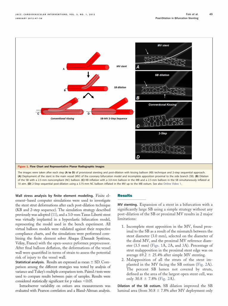
e
R
spl
d in t
J A C C : C A R D I O V A S C U L A R I N T E R V E N T I O N S , V O L . 5 , N O . 1 , 2 0 1 2 Foin et al.
J A N U A R Y 2 0 1 2 : 4 7 – 5 6 Post-Dilation in Bifurcation Stenting
49
Wall stress analysis by finite element modeling. Finite el-ement–based computer simulations were used to investigatethe stent strut deformations after each post-dilation technique(KB and 2-step sequence). The simulation strategy describedpreviously was adopted (11), and a 3.0-mm Taxus Liberté stentwas virtually implanted in a hyperelastic bifurcation model,representing the model used in the bench experiment. Allvirtual balloon models were validated against their respectivecompliance charts, and the simulations were performed com-bining the finite element solver Abaqus (Dassault Systèmes,Velizy, France) with the open-source pyformex preprocessor.After final balloon deflation, the deformations of the vesselwall were quantified in terms of strain to assess the potentialrisk of injury to the vessel wall.Statistical analysis. Results are expressed as mean � SD. Com-parison among the different strategies was tested by analysis ofvariance and Tukey’s multiple comparison tests. Paired t tests wereused to compare results between pairs of samples. Results wereconsidered statistically significant for p values �0.05.
Intraobserver variability on ostium area measurements was
Figure 1. Flow Chart and Representative Planar Radiographic Images
The images were taken after each step (A to D) of provisional stenting and po(A) Deployment of the stent in the main vessel (MV) of the coronary bifurcatioof the SB with a 2.5-mm noncompliant (NC) balloon. (C) KB inflation with a 3.010 atm. (D) 2-Step sequential post-dilation using a 3.75-mm NC balloon inflate
valuated with Pearson correlation and a Bland-Altman analysis.
esults
MV stenting. Expansion of a stent in a bifurcation with aignificantly large SB using a simple strategy without anyost-dilation of the SB or proximal MV results in 2 major
imitations:
1. Incomplete stent apposition in the MV, found prox-imal to the SB as a result of the mismatch between thestent diameter (3.0 mm), selected on the diameter ofthe distal MV, and the proximal MV reference diam-eter (3.5 mm) (Figs. 1A, 2A, and 3A). Percentage ofstrut malapposition in the proximal stent edge was onaverage 69.2 � 25.4% after simple MV stenting.
2. Malapposition of all the struts of the stent im-planted in the MV facing the SB ostium (Fig. 2A).The percent SB lumen not covered by struts,defined as the area of the largest open stent cell, wasonly 30.8 � 7.8% (Fig. 2A).
Dilation of the SB ostium. SB dilation improved the SB
tion with kissing balloon (KB) technique and 2-step sequential approach.del and incomplete apposition proximal to the side branch (SB). (B) Dilationballoon in the MB and a 2.5-mm balloon in the SB simultaneously inflated athe MV up to the MB ostium. See also Online Video 1.
st-dilan mo-mm
luminal area (from 30.8 � 7.8% after MV deployment only

tTtoOM
r abbr
J A C C : C A R D I O V A S C U L A R I N T E R V E N T I O N S , V O L . 5 , N O . 1 , 2 0 1 2
J A N U A R Y 2 0 1 2 : 4 7 – 5 6
Foin et al.
Post-Dilation in Bifurcation Stenting
50
to 74.6 � 11.3% after dilation of the SB, p � 0.0001) (Fig. 2B).Despite the rate of strut malapposition being reducedtoward the SB, SB dilation alone without further MVpost-dilation is not recommended because of the distortionof the stent at the MB ostium and the high risk of stentmalapposition opposite the SB (Figs. 1B and 3B). Averagerate of malapposition within the bifurcation was increasedfrom 47.0 � 8.5% before SB dilation (simple MV stenting)o 55.3 � 16.8% after only SB dilation, p � 0.25 (Fig. 4).
The 3D ostial measurements showed high intraoperatorreproducibility with a correlation between 2 successivemeasurements of 0.98 (Pearson correlation) and a bias ofonly 0.73 with a SD of 3.67 (Bland-Altman test). Individualdifferences were observed between stent design and betweendifferent samples of the same platform. The percentage ofostial stenosis remaining after final post-dilation rangedfrom a minimum of 9% (Taxus Liberté) to a maximum of46% (Promus Element). The study was, however, notstatistically powered to discriminate differences among in-
Figure 2. 3D Reconstruction of the Bifurcation Model After Deployment of
(A) MV stenting only without SB ostium opening. (B) SB dilation with a 2.5-mmsequence with redilation of the MV with a 3.75-mm NC balloon inflated proximview from the MV. Right: ostium view from the SB. 3D � 3-dimensional; othe
dividual platform designs.
Kissing balloon. Post-dilation with KB increased significantlythe SB lumen area compared with simple MV stenting withoutopening of the SB and post-dilation (79.1 � 8.7% vs. 30.8 �7.8%, p � 0.0001).
KB restored the stent apposition opposite the SB ostium,but the technique induced a significant asymmetrical expan-sion of the lumen proximal to the SB (Figs. 1C, 2C, and 3C).
he increase in the stent diameter with KB is also limitedo the regions where the 2 balloons overlap, leaving a riskf incomplete stent apposition at the proximal stent edge.n average, 30.7 � 26.4% of the struts at the proximalV stent edge remained malapposed despite KB (Fig. 4).
2-step SB-MV sequence. Sequential 2-step optimizationachieved an almost identical SB ostium opening to that ofKB: Lumen percentage area free of struts at the SB ostiumwas on average 79.1 � 8.7% after KB and 74.4 � 11.6%after the 2-step sequence (p � 0.25).
Application of sequential 2-step post-dilation restoredthe stent apposition opposite the SB ostium and completed
-mm Stent (Biomatrix Flex) and Successful Post-Dilation
balloon. (C) Simultaneous 2.5-mm � 3.0-mm balloon KB dilation. (D) 2-Stepthe MB ostium. (A to D) Left: longitudinal cut-open view. Middle: ostiumeviations as in Figure 1.
a 3.0
NCal to
apposition of the stent in the proximal MV (Figs. 1D and 2D,
0fptleiaoht
mtdtats
tbc
vemqdoh2
D
J A C C : C A R D I O V A S C U L A R I N T E R V E N T I O N S , V O L . 5 , N O . 1 , 2 0 1 2 Foin et al.
J A N U A R Y 2 0 1 2 : 4 7 – 5 6 Post-Dilation in Bifurcation Stenting
51
Online Video 1). Strut malapposition in the ostium after the2-step sequence was similar to KB (respectively, 24.9 �10.4% and 21.3 � 9.2% of struts malapposed, p � 0.36), asignificant reduction compared with MV stenting only (47.0 �8.5%, p � 0.0005) and SB dilation only (55.3 � 16.8%, p �.0001) (Figs. 2D and 3).
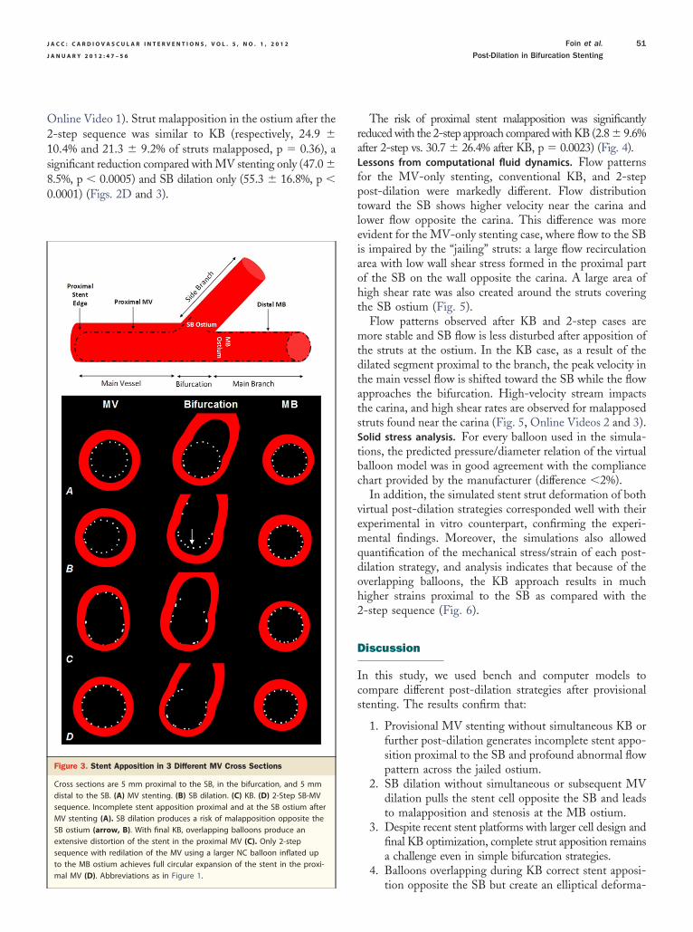
Figure 3. Stent Apposition in 3 Different MV Cross Sections
Cross sections are 5 mm proximal to the SB, in the bifurcation, and 5 mmdistal to the SB. (A) MV stenting. (B) SB dilation. (C) KB. (D) 2-Step SB-MVsequence. Incomplete stent apposition proximal and at the SB ostium afterMV stenting (A). SB dilation produces a risk of malapposition opposite theSB ostium (arrow, B). With final KB, overlapping balloons produce anextensive distortion of the stent in the proximal MV (C). Only 2-stepsequence with redilation of the MV using a larger NC balloon inflated upto the MB ostium achieves full circular expansion of the stent in the proxi-
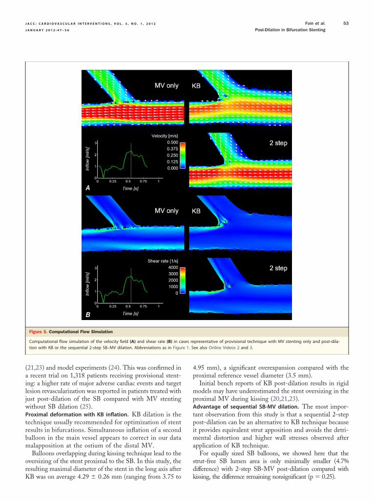
mal MV (D). Abbreviations as in Figure 1.The risk of proximal stent malapposition was significantlyreduced with the 2-step approach compared with KB (2.8 � 9.6%after 2-step vs. 30.7 � 26.4% after KB, p � 0.0023) (Fig. 4).Lessons from computational fluid dynamics. Flow patternsor the MV-only stenting, conventional KB, and 2-stepost-dilation were markedly different. Flow distributionoward the SB shows higher velocity near the carina andower flow opposite the carina. This difference was morevident for the MV-only stenting case, where flow to the SBs impaired by the “jailing” struts: a large flow recirculationrea with low wall shear stress formed in the proximal partf the SB on the wall opposite the carina. A large area ofigh shear rate was also created around the struts coveringhe SB ostium (Fig. 5).
Flow patterns observed after KB and 2-step cases areore stable and SB flow is less disturbed after apposition of
he struts at the ostium. In the KB case, as a result of theilated segment proximal to the branch, the peak velocity inhe main vessel flow is shifted toward the SB while the flowpproaches the bifurcation. High-velocity stream impactshe carina, and high shear rates are observed for malapposedtruts found near the carina (Fig. 5, Online Videos 2 and 3).Solid stress analysis. For every balloon used in the simula-ions, the predicted pressure/diameter relation of the virtualalloon model was in good agreement with the compliancehart provided by the manufacturer (difference �2%).
In addition, the simulated stent strut deformation of bothirtual post-dilation strategies corresponded well with theirxperimental in vitro counterpart, confirming the experi-ental findings. Moreover, the simulations also allowed
uantification of the mechanical stress/strain of each post-ilation strategy, and analysis indicates that because of theverlapping balloons, the KB approach results in muchigher strains proximal to the SB as compared with the-step sequence (Fig. 6).
iscussion
In this study, we used bench and computer models tocompare different post-dilation strategies after provisionalstenting. The results confirm that:
1. Provisional MV stenting without simultaneous KB orfurther post-dilation generates incomplete stent appo-sition proximal to the SB and profound abnormal flowpattern across the jailed ostium.
2. SB dilation without simultaneous or subsequent MVdilation pulls the stent cell opposite the SB and leadsto malapposition and stenosis at the MB ostium.
3. Despite recent stent platforms with larger cell design andfinal KB optimization, complete strut apposition remainsa challenge even in simple bifurcation strategies.
4. Balloons overlapping during KB correct stent apposi-
tion opposite the SB but create an elliptical deforma-
mpsflgpw
cqCbge
blmatmc
m
ii
fcrt
aesp(lr(u
f
tSf
iation
J A C C : C A R D I O V A S C U L A R I N T E R V E N T I O N S , V O L . 5 , N O . 1 , 2 0 1 2
J A N U A R Y 2 0 1 2 : 4 7 – 5 6
Foin et al.
Post-Dilation in Bifurcation Stenting
52
tion of the stent segment proximal to the SB with highstrains in the wall and increased risk of stent damageand injury to the vessel.
5. For provisional stenting of bifurcations, the sequentialSB-MV dilation appears to offer a more effectivemethod of final optimization than final KB.
Strut malapposition and thrombosis risk. Accumulating ev-idences show that malapposed drug-eluting stents (DES)have delayed and incomplete healing (12). Reports frompathological observations suggest that prolonged exposureto the disturbed flow pattern around unapposed and non-endothelialized struts in direct contact with the blood is oneof the factors leading to increased stent thrombosis (12,13).
Some clinical studies in which incomplete stent apposi-tion was assessed with intravascular imaging also suggest acorrelation between malapposition and a higher risk of stentthrombosis (14–16), but these observations are not yetentirely compelling and have to be confirmed in otherstudies.
In vitro models have shown that shear can activateplatelets (at a shear rate �1,000 s�1) in a dose-dependent
anner through von Willebrand factor binding to glyco-rotein (GP) Ib and GP IIb/IIIa receptors (17). Protrudingtent struts create back-facing steps that disturb the bloodow and result in flow separation and eddies with high shearradient (18). Post-mortem examinations and in vitro ex-eriments have shown that such flow patterns are associatedith increased platelet adhesion (13,18).This correlation is a particular concern in bifurcations,
onsidering the high rate of strut malapposition and fre-uent incomplete stent apposition observed in vivo (1–3,13).onventional stents are not designed to be implanted inifurcations, and post-dilation is required to correct stenteometry and improve strut apposition. As shown here,
Figure 4. Ostial Stenosis and Strut Malapposition Measured in the Bifurca
Results from micro-computed tomography measurement analysis after deploypost-dilation using KB and with the 2-step sequential SB-MV approach. Abbrev
ven when following recommendations on treatment of b
ifurcations, complete dilation of the ostium remains chal-enging in large SB without a dedicated platform. In vivo,
alapposition rates �50% have been reported at the ostiumfter bifurcation stenting, despite systematic final KB dila-ion (1). This might explain the high rate of stent thrombosis andajor adverse cardiac events still observed with percutaneous
oronary intervention in bifurcations (4–6,19).A simple and reliable implantation strategy to limitalapposition in bifurcations is therefore desirable.
What to do with the SB ostium: perspective from recenttrials. Dilation of the struts at the SB ostium and KBnflation are generally recommended in 2-stent strategies tomprove outcome and prevent SB reocclusion (9,20,21).
Final post-dilation is becoming increasingly controversialor a single-stent strategy, with initial results of a recentlinical trial showing that despite improving angiographicestenosis at the SB ostium, SB dilation and final KBhrough the stent do not reduce hard clinical endpoints (8).
Malapposed struts at the SB ostium are not visiblengiographically, with stent malappostion becoming appar-nt only when neointima and fibrin deposition cover thetruts left jailing the ostium. Early follow-up results inatients treated with DES and under antiplatelet therapies5,8) may underestimate the risk associated with leavingarge SB jailed. A late catch-up phenomenon has beeneported several years after DES implantation in humansfor review, see Finn et al. [22]), and it is not yet clear hownapposed DES struts heal.Long-term follow-up studies are therefore needed to assess the
ate of the jailed ostium and its clinical implications.SB balloons straighten during inflation and tend to pull
he MV stent struts toward the SB. The simple strategy ofB dilation alone is trading malapposition at the SB ostiumor malapposition at the MB ostium and does not appear
nd Proximal Stent Edge
f the stents (n � 26) in the MV (simple), after SB opening, and withs as in Figure 1.
tion a
ment o
eneficial. Similar observations have been reported in bench
trbm
orK
4p
mp
tpima
sd
re 1. S
J A C C : C A R D I O V A S C U L A R I N T E R V E N T I O N S , V O L . 5 , N O . 1 , 2 0 1 2 Foin et al.
J A N U A R Y 2 0 1 2 : 4 7 – 5 6 Post-Dilation in Bifurcation Stenting
53
(21,23) and model experiments (24). This was confirmed ina recent trial on 1,318 patients receiving provisional stent-ing: a higher rate of major adverse cardiac events and targetlesion revascularization was reported in patients treated withjust post-dilation of the SB compared with MV stentingwithout SB dilation (25).Proximal deformation with KB inflation. KB dilation is theechnique usually recommended for optimization of stentesults in bifurcations. Simultaneous inflation of a secondalloon in the main vessel appears to correct in our dataalapposition at the ostium of the distal MV.Balloons overlapping during kissing technique lead to the
versizing of the stent proximal to the SB. In this study, theesulting maximal diameter of the stent in the long axis after
Figure 5. Computational Flow Simulation
Computational flow simulation of the velocity field (A) and shear rate (B) in cation with KB or the sequential 2-step SB–MV dilation. Abbreviations as in Figu
B was on average 4.29 � 0.26 mm (ranging from 3.75 to k
.95 mm), a significant overexpansion compared with theroximal reference vessel diameter (3.5 mm).Initial bench reports of KB post-dilation results in rigidodels may have underestimated the stent oversizing in the
roximal MV during kissing (20,21,23).Advantage of sequential SB-MV dilation. The most impor-ant observation from this study is that a sequential 2-stepost-dilation can be an alternative to KB technique becauset provides equivalent strut apposition and avoids the detri-
ental distortion and higher wall stresses observed afterpplication of KB technique.
For equally sized SB balloons, we showed here that thetrut-free SB lumen area is only minimally smaller (4.7%ifference) with 2-step SB-MV post-dilation compared with
presentative of provisional technique with MV stenting only and post-dila-ee also Online Videos 2 and 3.
ses re
issing, the difference remaining nonsignificant (p � 0.25).

pv
gdPtpppcp
Mddd
odtoss
laopS
J A C C : C A R D I O V A S C U L A R I N T E R V E N T I O N S , V O L . 5 , N O . 1 , 2 0 1 2
J A N U A R Y 2 0 1 2 : 4 7 – 5 6
Foin et al.
Post-Dilation in Bifurcation Stenting
54
A previous bench study (23) using first-generation bare-metal stents compared KB technique with a simple MVredilation and found that both techniques were equallysuccessful for correcting stent stenosis in the MV induced by SBdilation.
The risk of proximal stent malapposition was, however,significantly reduced with the 2-step approach comparedwith KB and stenting MV only (2.8 � 9.6% after 2-step vs.30.7 � 26.4% after KB, p � 0.005, and 69.2 � 25.4% afterMV only, p � 0.001).
The sequential approach has the benefits of consider-ing the natural change in the MV diameter across thebifurcation and avoiding the proximal overstretching consecutiveto KB.
We are hypothesizing here that in provisional stenting,the benefits of opening the strut at SB with KB may beoutweighed by the stent overexpansion and potential injuryin the MV caused by the overlapping balloons proximal tothe SB during kissing.
Complete apposition of the stent struts proximal to theSB without detrimental overexpansion of the stent maylimit risk of stent thrombosis. Despite previous evidence(23,26,27) suggesting that a SB-MV or SB-MV-SB se-quence is suitable post-dilation after provisional stenting,clinical data evaluating this alternative for stent optimiza-tion are still needed.Study limitations. Our study results must be carefully inter-
reted because bench and computational models only pro-
Figure 6. Finite Element Analysis in the Model Bifurcation
Simulation of post-dilation with KB (A) showing the resulting high strains proxSequential SB-MV post-dilation (C) results in the circular expansion of the stenAbbreviations as in Figure 1.
ide a representation of the stent behavior in vivo. a
The impact of MV redilation on the final apposition andeometry of the stent is dependent on the position andiameter of the balloon used for MV redilation (Fig. 1).osition of the MV balloon for redilation may be harder
o control in vivo: Positioning of the MV balloon tooroximal may leave a risk of leaving some struts malap-osed opposite the SB carina, whereas the opposite,ositioning the balloon too distal, may cause a risk of thearina shifting if the balloon is sized according to theroximal reference diameter.In vivo, redilation of the MV across the SB to the distalB followed by a proximal post-dilation with a larger
iameter balloon (sized according to the proximal referenceiameter) may limit the chance of misaligning the balloonuring MV redilation.The model used did not include any lesions, and results
btained would certainly be affected by the presence ofisease. In particular, with extensive disease proximal tohe SB, malapposition after MV stenting is less likely toccur. Similarly, overstretching is expected to be lessignificant in a stiff, calcified vessel than in a compliantilicone model.
Benefits of KB technique have been extensively estab-ished for 2-stent strategies (7), and results presented herere only related to provisional treatment of bifurcations withnly 1 stent. However, similar results are expected forost-dilation of provisional T-stenting strategy when theB stent is not protruding into the MV lumen, and no
o the SB created by the 2 overlapping balloons simultaneously inflated (B).significantly more homogeneous strain distribution proximal to the SB (D).
imal tt and
dditional layer of struts is covering the SB ostium.

cem
ctcmm
C
J A C C : C A R D I O V A S C U L A R I N T E R V E N T I O N S , V O L . 5 , N O . 1 , 2 0 1 2 Foin et al.
J A N U A R Y 2 0 1 2 : 4 7 – 5 6 Post-Dilation in Bifurcation Stenting
55
The model represented a bifurcation with a large SB at arelatively acute takeoff angle. Results may be different insmaller diameter SB with wider SB angle. Low takeoff angleimplies a larger SB ostium area (28), and KB is usuallyrecommended in this type of geometry to avoid compromisingthe SB by carina shifting (29). In T-shape bifurcations with anangle �70°, the risk of carina shift is less significant, and byontrast, performing KB can produce an unfavorable straight-ning of the MV-SB angle. Sequential SB-MV post-dilationay be particularly appropriate for T-shape bifurcations.In the experiment, as well as in the simulation, optimal
ell crossing (mid-distal) was performed under visual con-rol before dilation of the SB and final post-dilation. In vivo,ontrol of cell recrossing and balloon position is significantlyore challenging, and therefore, a higher rate of strutalapposition is expected in the ostium.
onclusions
Stenting only the MV in a bifurcation without furtherpost-dilation produces incomplete stent apposition proximalto the SB, leaving stent struts malapposed at the SB ostiumthat disturb flow and increase the risk of stent thrombosis.Post-dilation is necessary to ensure full apposition of thestent, and here, we provided insights into some of thenegative consequences of KB and compared the techniqueto a sequential 2-step post-dilation without kissing.
Sequential post-dilation of the SB and MV may offer asimpler alternative to final KB inflation after provisionalbifurcation stenting.
Reprint requests and correspondence: Dr. Nicolas Foin, Inter-national Centre for Circulatory Health, St Mary’s Hospital andImperial College, London W2 1LA, United Kingdom. E-mail:[email protected].
REFERENCES
1. Tyczynski P, Ferrante G, Moreno-Ambroj C, et al. Simple versuscomplex approaches to treating coronary bifurcation lesion: directassessment of stent strut apposition by optical coherence tomography.Rev Esp Cardiol 2010;63:904–14.
2. Costa RA, Mintz GS, Carlier SG, et al. Bifurcation coronary lesionstreated with the “crush” technique: an intravascular ultrasound analysis.J Am Coll Cardiol 2005;46:599–605.
3. Hahn J-Y, Song YB, Lee S-Y, et al. Serial intravascular ultrasoundanalysis of the main and side branches in bifurcation lesions treatedwith the T-stenting technique. J Am Coll Cardiol 2009;54:110–7.
4. Colombo A, Bramucci E, Saccà S, et al. Randomized study of the crushtechnique versus provisional side-branch stenting in true coronarybifurcations: the CACTUS (Coronary Bifurcations: Application of theCrushing Technique Using Sirolimus-Eluting Stents) study. Circula-tion 2009;119:71–8.
5. Hildick-Smith D, de Belder AJ, Cooter N, et al. Randomized trial ofsimple versus complex drug-eluting stenting for bifurcation lesions: theBritish Bifurcation Coronary study: old, new, and evolving strategies.
Circulation 2010;121:1235–43.6. Steigen TK, Maeng M, Wiseth R, et al. Randomized study on simpleversus complex stenting of coronary artery bifurcation lesions: theNordic Bifurcation study. Circulation 2006;114:1955–61.
7. Ge L, Airoldi F, Iakovou I, et al. Clinical and angiographic outcomeafter implantation of drug-eluting stents in bifurcation lesions with thecrush stent technique: importance of final kissing balloon post-dilation.J Am Coll Cardiol 2005;46:613–20.
8. Niemela M, Kervinen K, Erglis A, et al. Randomized comparison offinal kissing balloon dilatation versus no final kissing balloon dilatationin patients with coronary bifurcation lesions treated with main vesselstenting: the Nordic-Baltic Bifurcation study III. Circulation 2011;123:79–86.
9. Stankovic G, Darremont O, Ferenc M, et al. Percutaneous coronaryintervention for bifurcation lesions: 2008 consensus document from thefourth meeting of the European Bifurcation Club. EuroIntervention2009;5:39–49.
10. Ormiston JA, Webster MWI, Webber B, Stewart JT, Ruygrok PN,Hatrick RI. The “crush” technique for coronary artery bifurcationsenting: insights from micro-computed tomographic imaging of benchdeployments. J Am Coll Cardiol Intv 2008;1:351–7.
11. Mortier P, Holzapfel GA, De Beule M, et al. A novel simulationstrategy for stent insertion and deployment in curved coronary bifur-cations: comparison of three drug-eluting stents. Ann Biomed Eng2010;38:88–99.
12. Joner M, Finn AV, Farb A, et al. Pathology of drug-eluting stents inhumans: delayed healing and late thrombotic risk. J Am Coll Cardiol2006;48:193–202.
13. Nakazawa G, Yazdani SK, Finn AV, Vorpahl M, Kolodgie FD,Virmani R. Pathological findings at bifurcation lesions: the impact offlow distribution on atherosclerosis and arterial healing after stentimplantation. J Am Coll Cardiol 2010;55:1679–87.
14. Cook S, Wenaweser P, Togni M, et al. Incomplete stent appositionand very late stent thrombosis after drug-eluting stent implantation.Circulation 2007;115:2426–34.
15. Cook S, Ladich E, Nakazawa G, et al. Correlation of intravascularultrasound findings with histopathological analysis of thrombus aspi-rates in patients with very late drug-eluting stent thrombosis. Circula-tion 2009;120:391–9.
16. Ozaki Y, Okumura M, Ismail TF, et al. The fate of incomplete stentapposition with drug-eluting stents: an optical coherence tomography-based natural history study. Eur Heart J 2010;31:1470–6.
17. Holme PA, Orvim U, Hamers MJAG, et al. Shear-induced plateletactivation and platelet microparticle formation at blood flow conditionsas in arteries with a severe stenosis. Arterioscler Thromb Vasc Biol1997;17:646–53.
18. Duraiswamy N, Schoephoerster RT, Moreno MR, Moore JE. Stentedartery flow patterns and their effects on the artery wall. Annu Rev FluidMech 2007;39:357–82.
19. Brar SS, Gray WA, Dangas G, et al. Bifurcation stenting withdrug-eluting stents: a systematic review and meta-analysis of ran-domised trials. EuroIntervention 2009;5:475–84.
20. Ormiston JA. Drug-eluting stents for coronary bifurcations: benchtesting of provisional side-branch strategies. Catheter CardiovascInterv 2005;67:49–55.
21. Lefèvre T, Louvard Y, Morice M-C, et al. Stenting of bifurcationlesions: classification, treatments, and results. Catheter CardiovascInterv 2000;49:274–83.
22. Finn AV, Nakazawa G, Kolodgie FD, Virmani R. Temporal courseof neointimal formation after drug-eluting stent placement: is ourunderstanding of restenosis changing? J Am Coll Cardiol Intv2009;2:300 –2.
23. Ormiston JA. Stent deformation following simulated side-branchdilatation: a comparison of five stent designs. Catheter CardiovascInterv 1999;47:258–67.
24. Mortier P, De Beule M, Van Loo D, Verhegghe B, Verdonck P. Finiteelement analysis of side branch access during bifurcation stenting. MedEng Phys 2009;31:434–40.
25. Gwon HC, Song Y. TCT-13. Side branch ballooning after main vesselstenting may increase the long-term risk of target lesion revasculariza-tion rate in the coronary bifurcation lesion (abstr). J Am Coll Cardiol
2010;56 Suppl:B3.
J A C C : C A R D I O V A S C U L A R I N T E R V E N T I O N S , V O L . 5 , N O . 1 , 2 0 1 2
J A N U A R Y 2 0 1 2 : 4 7 – 5 6
Foin et al.
Post-Dilation in Bifurcation Stenting
56
26. Pan M, Medina A, de Lezo JS, et al. Coronary bifurcation lesionstreated with simple approach (from the Cordoba and Las Palmas[CORPAL] Kiss trial). Am J Cardiol 2011;107:1460–5.
27. Gastaldi D, Morlacchi S, Nichetti R, et al. Modelling of the provisionalside-branch stenting approach for the treatment of atheroscleroticcoronary bifurcations: effects of stent positioning. Biomech ModelMechanobiol 2010;9:551–61.
28. Mortier P, Van Loo D, De Beule M, et al. Comparison of drug-elutingstent cell size using micro-CT: important data for bifurcation stentselection. EuroIntervention 2008;4:391–6.
29. Gil RJ, Vassilev D, Formuszewicz R, Rusicka-Piekarz T, Doganov A.
The carina angle: new geometrical parameter associated with peripro-cedural side branch compromise and the long-term results in coronarybifurcation lesions with main vessel stenting only. J Interv Cardiol2009;22:E1–10.
Key Words: bifurcation � kissing � malapposition �post-dilation � stent.
APPENDIX
For accompanying videos, please see the online version of this article.